form metrology for am - university of nottingham in-process / final part, tests for higher volumes,...
TRANSCRIPT


Form metrology
• Measurement of the external shape of something
• Involves ‘large-scale’ measurements of metres down to centimetres generally with an accuracy of 100’s of micrometres

Why is form metrology important?
• Allows mass-assembly of mechanical products Exact measurement of shape allows for predictable performance when bringing parts together in an assembly and is required to achieve a specific performance (car engine, turbine blade)
• Keeping form controlled to tight tolerances minimises material waste In some cases this is the most important part of the product cost (improves profits for manufacturing plants, makes them more competitive)
Types of form metrology
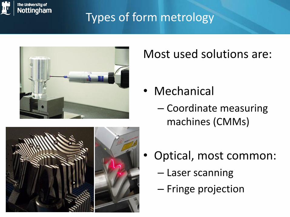
Most used solutions are:
• Mechanical
– Coordinate measuring machines (CMMs)
• Optical, most common:
– Laser scanning
– Fringe projection

Constraints introduced by AM
Constraint type Constraint Reason
Surface texture
Diffuse reflectance (an example of a flat surface created via a selective laser melting metal process is shown in Figure 3)
Typical surfaces produced via layering and powder based metal AM manufacturing technology are not optically smooth to visible wavelengths
Form geometry
Freeform, multiple occlusions and shadows exist
Little restriction in created geometry permits for complicated shapes with large number of discontinuities and line of sight occlusions present
Material range Appreciable variation of absorption/reflection properties between different materials
Inhibits the overlay of specific wavelengths, more important for laser triangulation than structured light

Current focus of AM metrology activities in group
Three top priorities:
• Investigation of the UK’s requirements for AM metrology
• Creating a technical review of existing form measurement systems and their applicability to AM
• Use of a priori knowledge (structured light system models and object CAD data) to improve the measurement process via IRM (information-rich metrology)

• The UK’s requirements for AM metrology
• Completing the technical review of existing form measurement systems
• Use of a priori knowledge (structured light system models and object CAD data) to improve the measurement process via IRM (Information Rich Metrology)
Current focus of AM metrology activities in group

Current status of UK AM metrology needs review
• Investigation plan for UK AM metrology:
– Look at global AM landscape
– Create a realistic snapshot of the current UK AM industry and supply chain
– Identify the greatest metrology challenges for AM industry (currently in collection)
– Tie challenges in with fellowship project aims

Timeline of EPSRC effort to collect AM data
• The EPSRC AM CIM’s aim is to produce a UK-specific document regarding the current roadblocks in AM and an actionable plan to present to government after election and in time for the budget
• Their timeline is very relevant and close to our project/fellowship needs • Metrology is placed in the top requirements for evidence collection and hence will
be a big part of this report

Metrology is mentioned among the most critical barriers for the growth of the UK AM industry
Code title # workshop Post-Its
# references from on-line submissions
Summary of common perceived barriers:
Materials 138 223 Understanding properties in different processes/machines/applications, QA, costs, availability (IP constraints, independent suppliers), use of mixed materials, recyclability, biocompatibility.
Design 99 208 Need for guides and education programmes on design for AM – better understanding of design for AM constraints, availability of AM-skilled designers, security of design data.
Skills / education 68 125 Lack of appropriate skills (design, production, materials, testing) preventing adoption, up-skilling current workforce vs. training of next generation, education of consumers, awareness in schools.
Cost / investment / financing
62 156 Funding to increase awareness and reduce risk of adoption (testing, scale-up, machine purchase) – especially for SMEs, understanding of full costs (inc. post-processing, testing), cost of materials.
Standards / regulation
61 105 Perceived or actual lack of standards – all sectors / sector specific (esp. aero / health / motorsport), for processes / materials / software / products / applications.
Measurement / inspection / testing
23 127 Need data libraries, standards for tests (general and sector specific), materials/ in-process / final part, tests for higher volumes, non-destructive testing, QA through lock-in cf. open access to data.
IP / protection / secrecy
17 14 Balancing need for openness to share knowledge with need for commercial protection to capture value from investments, enforcement of IP rights.
Source: Update report 2 – UK AM National Strategy Effort http://www.amnationalstrategy.uk

Sector % of
contributions Sector % of
contributions Manufacturing 55 Automotive 3
Materials 34 Motorsport 3 Machinery 19 Nuclear 3
Information 10 Electronics 3 Aerospace 12 Construction 1
Defence 10 Rail 1 Creative
industries 7 Marine 1
Life sciences 5 Oil and Gas 1
In total 143 organisations have provided responses out of which the UK AM landscape per sector was as follows:
First results of EPSRC effort: UK AM Landscape

Current focus of AM metrology activities in group
• The UK’s requirements for AM metrology
• Completing the technical review of existing form measurement systems
• Use of a priori knowledge (structured light system models and object CAD data) to improve the measurement process via IRM (Information Rich Metrology)

Technical review
The technical report created which has been sent to Review of Scientific Instruments and is at peer review stage describes the following:
• Presentation of overview of form measurement systems available for 3D measurement
• Comparison of 3D form measurement systems and selection of the ones most applicable for industrial AM applications
• Calculation of fundamental accuracy and uncertainty limits for metrological solutions available for AM (laser triangulation, fringe projection)
• Presentation of practical considerations and additional sources of uncertainty (beyond the fundamental ones) and discussion of areas which need improvement

Summary of Technical Review: Measurement tolerances required in industry
Figure from: E. Savio, L. De Chiffre, and R. Schmitt, CIRP Ann. - Manuf. Technol. 56, 810 (2007).

Other industrial requirements
Characteristic: Value used: Source:
Maximum volume of measurement area (distance):
Up to: (2000 × 2000 ×1500) mm
Recommended by VDI/VDE 2634-1 standard on industrial non-contact 3D scanning
Dimensional tolerance: Varies with industry, typically ≤ 100 μm (±50 μm)
As per previous figure
Resolution and accuracy:
As high as possible, typically ten times better than the tolerance range in order to provide adequate measurement confidence interval and appropriate process control.
N/A
Measurement time: As fast as possible, typical requirement is to be faster than the manufacturing process itself.
N/A

Active vs. Passive systems
• There are two general families of 3D optical measurement active and passive: – By active systems we mean systems that use their own
light source to perform the measurement
– By passive systems we refer to systems that depend on already available light to perform the measurement
• Generally, for higher measurement speed and accuracy people select active systems whereby for cost effectiveness people prefer passive

List of optical systems available
3D form measurement technique Passive Active
Laser triangulation X
Structured light X
Stereo vision X
Photogrammetry X
Time of flight X
Interferometry X
Moiré fringe range contours X
Shape from focusing X X
Shape from shadows X
Texture gradients X
Shape from shading X
Shape from photometry X
Classification of active and passive 3D form measurement techniques (Source: G. Sansoni, M. Trebeschi, and F. Docchio, Sensors 9, 568 (2009) )

Active form measurement systems
• For our internal spec, a measurement volume of (700x700x700) mm and an accuracy smaller or equal to 100 μm is required to accommodate most AM. Laser triangulation and pattern projection are the most appropriate techniques to measure AM parts.
Source: S. Se and N. Pears, 3D Imaging, Analysis and Applications (2012)

Comparison of current popular non-contact optical form technologies in industry
Laser Triangulation Fringe Projection
Point-to-point or Line-to-line Areal
Angle based Intensity based
Direct measurement within field of view
Requires ambiguity removal: -Wrapped phase -Scaling factor
Less software involved More software steps involved
Laser point illumination Lamp illumination
Moving parts No moving parts


Where do we go from here?
A) Improve fringe projection and laser scanning
B) Develop other measurement technologies which could be used for form measurement


Active shape from focus
Projected patterns used to texturize scene in order to assist with reconstruction of featureless objects.


Close-range photogrammetry
Source: L.M. Galantucci, F. Lavecchia, and G. Percoco, J. Comput. Inf. Sci. Eng. 13, 044501 (2013)

Comparison chart of promising techniques:
Technique: Best dimensional resolution reported in height axis:
Measurement Range:
Type of view: Works on optically rough surface:
Active focus detection through shear interferometry
10 μm (on optically smooth surfaces) resolution reduced for rough surfaces
300 mm Point-to-point YES
Time of flight 15 μm 500 mm Full field YES
Close-range photogrammetry
~15 μm 30 mm - 100 ma Full field YES
Volume Holographic Profilometry
15 μm – millimetres 20 cm – 2 m Full field YES
Holographic Profilometry
10 μm 50 mm - 300 mm depending on object reflectance
Full field YES
Moiré profilometry typically ~25 μm depends on grating frequency used
N/A Full field YES

Current focus of AM metrology activities in group
• The UK’s requirements for AM metrology
• Completing the technical review of existing form measurement systems
• Use of a priori knowledge (structured light system models and object CAD data) to improve the measurement process via IRM

Flow chart of IRM-enhanced structured light system operation for AM
3D model of object to be measured (AM CAD)
Simulation of projections for specific
object model in combination with the
instrument model.
Selection of minimum amount of views required to fully describe object
Send optimized views to measurement rig to take
measurements
Comparison of initial model with points
acquired
Fill-in gaps found either with new projections or
more accurate secondary system
(triangulation)
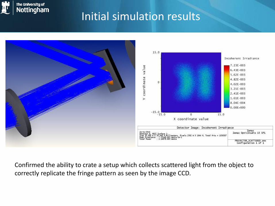
Initial simulation results
Confirmed the ability to crate a setup which collects scattered light from the object to correctly replicate the fringe pattern as seen by the image CCD.

NUB3D SIDIO XR Structured light 3D scanning system:
Form Metrology lab at UoN


Future plan
Aim: ‘One-shot’ 3D reconstruction system with maximum available accuracy and resolution via multi-view paradigm and inspection planning that will be customized to specific objects.
