forestry commission booklet: aids to working conifer …file/fcbk...aids to working conifer...
TRANSCRIPT

FO R E ST R Y COM M ISSIO N
BOOKLET No. 8
Aids to Working Conifer Thinnings
in
CANT HOOK
E D IN B U R G H H E R M A J E S T Y ’S S T A T I O N E R Y O F F I C E
THREE SH IL L IN G S NETForestry Commission
ARCHIVE

I It l! I
.■
's&M ■ -He"-.
<' f -
'Mgfe
m m % m m m| ■ mm% m r' Ml ; m-.•'. y . ;• -.i.;. w '• - 'V •-••’••:: v -a *.• -. • .-• :> .w,- : ‘.cy •>'!<;• .v,-
gjf|*:Ar-
i
, -5 iy ~ Sfe>£s<‘J4, ■
Ira KM m
a 7 ;?i&J '<’; -.t >, x"Vva'» f I & -• §q$&tt \ ? ~ Ip i' > . '- . ' ' 4 ' 1 Si A:3:%i
' :;¥<■
■ ■
‘ f . . •- ' ’«- .'.rViV'■»-'.
.<&. 4 L . d K.
* » ' A - v g
av .. a ;■'■■■
S f » i S ® « f e a s :, ;,v_ ; „ v . _ . , M «..,
■ - ’ - r V * ’ ’ ‘ ; :-f :
N:V?.t-'r
’. - 'n.-.V.V ;>\ :̂Wm aft$tes.7 H i-k'i^n r̂#&’4 *
■
J¥SB
if l|f £!p:HEM0r£&.
•?#>!.„..._ '>a. '■ * if< ,:' /
A i;
i , 1, v '» .«-.7,i,. . 1 ffiS
•Mk'i -
$* Mi
V- r mm
% v .
S I
' •'• >7vl';:.’ U7;r f>« ->‘•̂ >- af iNNxNiiMa?®SaSE'

Aids to Working Conifer Thinnings
By S. Forrester, B.Sc.Forestry Commission
FO RESTRY COM MISSION
BOOKLET No. 8
E D I N B U R G H
H E R M A J E S T Y ’S S T A T I O N E R Y O F F I C E
1962

INTRODUCTIONThis booklet is intended as a guide to some items of equipment
which may not be widely known, and particularly to some which have been developed only in the past few years.
The need for, or the value of, some of them has been emphasised during the course of investigations, by the Work Study Section of the Forestry Commission, into the felling, extraction and conversion of conifer thinnings. Some of these items were in regular use in some parts of this country before that Section existed. Others are ideas imported from abroad, particularly Sweden. In many cases, development has been carried out by the Section, but in few, if any, cases can the Section claim to have done this unaided. The only claim made is that here is assembled a varied assortment of gadgets each of which is of some value in some places. It is hoped that having them all described in one booklet will be of help to foresters throughout the country.
Thanks are due to all those forest workers, foresters and forest officers, too numerous to mention, whose ideas, criticism, and help have produced the results herein.
The purpose of these tools is mainly to make work easier— reducing the effort involved or making operations quicker. Many are intended to eliminate or ease heavy lifting with its attendant risks. Others make it possible for one man to do a job which otherwise requires two. Not only is the time of the second man saved while actually doing the job but also his time in coming to the assistance of his mate. In all cases there is a reasonable criticism that the extra tool is an additional burden. Our belief is that properly used in the right place all these tools will justify their keep.
The aims in compiling this booklet have been:-1. To show what has been produced.2. To show what it will do.3. To show where and when it can be of value.
Some of the gear described has a specific use, while some can be used in two or three different ways in different situations. In general the items are arranged in the order in which the main use falls in the production line, from felling to extraction and conversion.
We are sure that there are still plenty of ideas in limited use or in the minds of foresters throughout the country. The Work Study Section of the Forestry Commission is always glad to have ideas, and will be glad too to have comments on the tools already described.
2

THE EQUIPMENT DESCRIBEDItem
A. A ID S I N F E L L I N GUses
1. Long-hand led fel l ing tongs (p. 5 and plate 1)
2. Canthook (p. 7, cover and plate 2)
3. Rope, pole and hook (P- 9)
Felling in dense crops of 2-4 h. ft. Hand extraction of poles.Felling large trees (over 4 h. ft.). Timber handling.Felling in very dense under- thinned crops (particularly Sitka spruce).
B. A ID S TO E X T R A C T I O N4. Extraction rope (p. 11)5. Hand skid pan (p. 13 and
plate 3)
6. Sappie (p. 15)
7. Border sledge (p. 17 and plate 4)
8. Stacking trestle (p. 19 and plate 5)
Hand extraction of peeled poles. Hand extraction.Felling under-thinned crops of 5-10 h. ft.Hand extraction on steep slopes. Gathering loads for extraction. Horse extraction on level or rolling ground.Extraction.
C. A ID S TO C O N V E R S I O N9. Wooden saw horse (p. 21 Peeling and crosscutting by hand,
and plate 6)10. Log jack (p. 23 and plate Crosscutting.
7)11. Roller-top stand (p. 25 Crosscutting on a sawbench.
and plates 8 and 9)12. Towing arm (p. 27 and Moving sawbench and peeling
plate 10) machines.
D. A ID S TO T R A N S P O R T A N D H A N D L I N G13. Rope sling (p. 29 and Loading pulpwood, or props, with
plate 11) hoist.14. Lorry fittings (p. 31 and Transporting pulpwood, props, etc.
plate 12)15. Tongs, pulphook and Handling timber,
gloves (p. 33)16. Measuring rods (p. 35) Measuring, Crosscutting.
A list o f suppliers is given a t the end o f the booklet.
3

F ig . 1. The Long-handled Felling Tongs.
A. AIDS IN FELLINGOften the most difficult operation during thinning is getting the
trees down, after the actual cutting with the saw has been completed. This is particularly true in spruce crops and in the early thinnings, when the canopy is most dense.
This section deals with three tools for this job. Their relation with each other in the different circumstances is :-1. Long-handled felling tongs.—Thinning of trees averaging 2-4
hoppus feet.2. Canthooks.—Thinning of trees averaging 4-20 hoppus feet.3. Rope, pole and hook.—Thinning of trees averaging 4-10 hoppus
feet, in underthinned plantations.In addition, the hand skid pan (page 13) can be used for thinnings
in similar situations as “3” above.These devices will help to avoid the common, but risky practices
of climbing the lodged trees, to force them down, or cutting the tree supporting the lodged one.
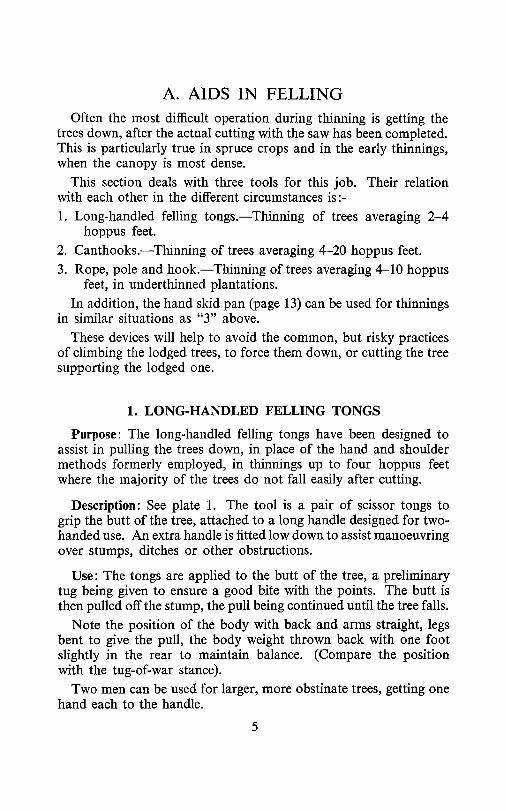
1. LONG-HANDLED FELLING TONGS
Purpose: The long-handled felling tongs have been designed to assist in pulling the trees down, in place of the hand and shoulder methods formerly employed, in thinnings up to four hoppus feet where the majority of the trees do not fall easily after cutting.
Description: See plate 1. The tool is a pair of scissor tongs to grip the butt of the tree, attached to a long handle designed for two- handed use. An extra handle is fitted low down to assist manoeuvring over stumps, ditches or other obstructions.
Use: The tongs are applied to the butt of the tree, a preliminary tug being given to ensure a good bite with the points. The butt is then pulled off the stump, the pull being continued until the tree falls.
Note the position of the body with back and arms straight, legs bent to give the pull, the body weight thrown back with one foot slightly in the rear to maintain balance. (Compare the position with the tug-of-war stance).
Two men can be used for larger, more obstinate trees, getting one hand each to the handle.
5

There are two dangers—over-balancing backwards if the tongs slip, and catching the toes under the butt; these can be avoided by ensuring a good grip before putting on the full strain, and by correct foot positioning. To limit the risk of the tongs slipping, the points must be kept sharp.
Supplementary Use: The tongs are also useful for gathering poles into loads ready for extraction, or for hand extraction over short distances.
Scope: The tool is mainly of use in spruce plantations. Where the average pole being felled is between two and four hoppus feet, the trees can often be pulled down easily by hand. Conversely where the average is over four hoppus feet, the trees are largely too heavy to handle even with tongs. At this stage too the trees in a normally thinned stand tend to fall under their own weight. (See Canthooks for felling, page 7). In other species the value is less definite but the tongs may prove of value in first thinnings within these size limits.
Cost: About £2 10s.
6

2. CANTHOOKS FOR FELLINGPurpose: After the first two or three thinnings in a plantation,
the trees will generally fall under their own weight, particularly if well directed. Even expert fellers, however, occasionally have a tree lodged in the crowns of its neighbours. If the trees average under about four hoppus feet, dislodging them is relatively easy with the long-handled felling tongs (page 5). For larger trees many fellers use a pole cut in the wood to lever the butt off the stump. Others use a canthook to twist the tree out of its rest in the neighbouring crowns.
Description: See Plate 2 and cover drawing. Two sizes of canthook are generally available:
Sm all LargeLength of hook (from pivot
to point) .. .. l-\ inches 10 inchesOpening (end of pole to
point of hook) .. 10 inches 14 inches approx.Handle .. .. .. 2 ft 6 in-3 ft 4 ft—5 ftIf the hook has a good point it will grip a log larger than the
opening. The actual size possible depends on the shape of the tree but as a rough guide the small size will take a tree up to about 14 or 15 inches butt diameter, and the large one 18 or 20 inches.
Use: If a tree is lodged in such a way that it is easy to lever the butt backwards and if it is not firmly caught, it may well be better to use a pole as a lever to pull the tree off the stump. In other cases a twist with the canthook on the butt may roll the crown free of the obstructions, or a rocking motion with the canthook may shake a tree down between others. Experience is the best guide as to which method to use in individual cases.
The canthook is also useful for turning large trees to allow snedding the underside.
In using the canthook, a tug to check that a firm grip is obtained is a useful safety habit before putting the full weight on the handle.
Scope: The small canthook will not prove large enough, on account of size of grip and length of handle, where the average tree is much above ten hoppus feet. The large size will manage up to about twenty hoppus feet average tree. Below about four hoppus feet average the long-handled felling tongs are more useful in some circumstances.
Other Uses: The canthook is, of course, largely used for rolling and turning heavy timber. It can be of value in this way during measuring, stacking, loading, unloading or similar handling operations.
The cost of these canthooks is about £2 for the small one and £3 for the large one.
7


Plat
e 1.
The
long
-han
dled
fe
lling
to
ngs
in Si
tka
spru
ce
of
abou
t tw
o ho
ppus
fe
et.

Plate 2. The canthook twisting a tree out o f the canopy.

Plat
e 3.
The
hand
sk
id pa
n pr
even
ts
the
butt
of a
tree
sinki
ng
in so
ft gr
ound
.
Plat
e 4.
The
Bord
er
sled
ge,
part
ially
lo
aded
.


Plat
e 6.
A w
oode
n saw
ho
rse.
Th
e po
le is
stead
y wh
ile
bein
g sa
wn.

3. THE ROPE, POLE AND HOOK
Purpose: In underthinned plantations with large trees, 4-10 h. ft., the tongs and canthooks already described are not of great value. The trees are too heavy to handle even with the tongs, and are so firmly held by adjacent trees that use of the canthook is slow and laborious. The rope, pole and hook are designed to pull the trees down past their neighbours.
Description: The hook is made of § inch round steel bar, tied or spliced to a 20 foot length of two inch circumference rope. The pole should be about 15 feet long and as light and thin as possible.
Use: One of a pair of fellers clears the brash round the tree and axes off spurs if necessary. The other jams the hook on top of the pole, the tip of the pole going into the ring, and hooks it over a stout branch as high as possible on the tree. The branch should be as far round the back as can be reached from the front. The pole is removed and the rope laid out in the direction of fall. The two men then saw about seven-eighths of the way through the tree. While one man axes through the hinge, the other directs the tree by pulling on the rope and pulls it right down. The second man assists if necessary.
Scope: This method, requiring two men, is basically inefficient, and the equipment is cumbersome, so that it should only be used when no other is practicable.
Source: The rope can be bought from an ironmonger. The pole can be cut in the wood from a small dead, but still sound, tree. A blacksmith will have no difficulty making up a hook from the diagram.
F ig . 3. The H ook o f the Rope, Pole and H ook
9

F ig . 4. U sing the Extraction Rope.
10

B. AIDS TO EXTRACTIONNo one method is suitable for all forest extraction, even if con
sideration is limited to one country, or even to one forest. The methods outlined may help to augment the forester’s repertoire of methods and give him help for some particular circumstance. The last item in this section, the stacking trestle, is useful, however with many different methods of extraction.
4. EXTRACTION ROPE
Purpose: For short distances, steep slopes, and small poles, or some combinations of these circumstances, extraction of poles by hand can compete with other methods if suitable equipment is used. The long-handled felling tongs, (page 5), or the smaller tongs, (page 33), can be used, but if a fair amount of work is involved a very convenient method is to use a rope sling.
Description: The equipment is simply a six yard length of two inch circumference rope spliced into a loop. Sisal or manilla hemp rope can be used, the former being cheaper.
Many different arrangements of chains, wires and ropes, with or without handles, have been seen. None, have any clear advantage over a simple rope.
Use: A bight of the rope is passed round the end of the pole, the other end passed through this, and the pole simply pulled out.
Scope: The practical limits on distance and size of pole are about fifty yards and two hoppus feet average. If the poles are freshly peeled, or the slope is favourable, these limits can be exceeded. In addition, a reduction in the size could increase the worthwhile distance, and vice versa.
On very steep ground where horse or tractor extraction becomes almost or completely impossible, hand extraction may be worthwhile for quite long distances. On this ground, however, the sappie (page 15), is more useful.
Source: Any good ironmonger should be able to supply rope. If none of the forest staff can splice, the local scout troop will no doubt be glad to help.
11

12
Fig
. 5.
The
Han
d Sk
id
Pan
.

5. THE HAND SKID PAN
Purpose: 1. The hand skid pan is designed to make poles slide more easily over the ground for hand extraction. In consequence, larger poles could be worth extracting by hand, or for longer distances, than with some other methods of hand extraction. This may be specially useful if horses are in short supply, or if a programme does not warrant employment of a horse.
2. The skid pan can also be used for taking trees down in tall underthinned plantations.
Description: See plate 3. The implement is a flat bottomed steel sledge, three feet long. A toothed bolster supports the butts of the poles; these are held in place by the wire rope with which the skid pan is pulled.
Uses: 1. One or more poles are placed on the bolster and the rope hooked round them. Pulling the skid pan tightens the rope round the poles.
2. The skid pan is placed close up to the tree after sawing off, and the wire rope is hooked round the butt. Pulling on the rope shifts the tree on to the rear of the skid pan, which is then drawn away with the tree until the latter falls. Large trees may require to be levered on to the skid pan. This method is also useful on slopes where the skid pan slides away with the tree immediately the butt is on it.
Scope: The skid pan is relatively heavy, 22 pounds, and only justifies its use in extraction over relatively long distances, 75-100 yards. In felling, the rope, pole, and hook method has been more generally accepted for the type of conditions where both can be useful, but the skid pan may prove useful if it is in use for extraction anyway.
The cost of the skid pan is about £7.
13

F ig. 6. The Sappie.
14

6. THE SAPPIE
Purpose: The sappie is a tool with a wide range of uses in handling timber in the steep hill country of Central Europe. It has been used only in isolated parts of this country, but may have a wider application, especially for hand extraction.
Description: There are several varieties from which to choose, but that most likely to be useful in Britain is a steel spike, rather the shape of a curlew’s beak, set on the end of an axe shaft.
Use: There are two ways of using the sappie, either as a lever to clear a pole from some snag, or driven in to a log it can be used to pull it along the ground. For levering, firm ground is necessary. For hand extraction it is ideal for use on steep ground where the poles are tending to slide themselves, and only need occasional help. In these circumstances the sappie can be quickly withdrawn from the pole as it slides downhill.
Scope: Where a sustained pull over some distance is required a rope is better, but for short drags of a few yards, such as occur on steep slopes or in making up horse loads, the sappie is more suitable.
The sappie costs about £1 10s.
15

\< -̂b) -V\
16
Fig
. 8.
The
Bord
er
Sled
ge.

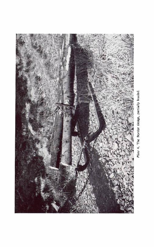
7. THE BORDER SLEDGE
Purpose: In horse dragging or tushing on peaty ground the size of load is normally limited to 6 or 7 hoppus feet, and considerable damage is caused to the drag routes. These may be so cut up and scoured out, that the operation is slowed down, and eventually the routes may become impassable. The border sledge, based on Swedish models, allows a larger load with less resistance and eliminates much of the damage to the drag road.
Description: See plate 4. This sledge is of steel construction with two runners four feet long, articulated with the cross members to allow them to follow the irregularities of the ground individually. On the main cross member is a swivelling bolster to which the poles are secured by a chain and wire rope, tightened by a ratchet device. The width of the sledge is three feet and the weight 125 pounds, making it manageable on the moderate slopes where it is suggested for use.
Use: Where possible the men felling should gather the poles into loads of convenient size. With larger poles the horseman may have to gather the loads himself by tushing. Reasonable extraction routes are required and racks may have to be cut to use the sledge effectively.
Two handles are provided on the rear of the runners to allow the horseman to turn the sledge and place it conveniently for loading. The butts of the poles are lifted on to the bolster and secured with the chain and wire. The side chains of the harness are attached direct to the attachment rings on the front of the runners. No swingle-tree is required.
On reaching the roadside the ratchet is released by pulling on the extension of the pawl, and the poles are lifted off for stacking. On page 18 is shown a trestle to simplify this part of the operation.
Loads of 15 to 20 hoppus feet are possible with the sledge.
Scope: For short distances, up to about 75 yards, the time saved in taking a large load is offset by the extra time spent loading the sledge as against tushing. The benefit of the sledge is greater the longer the distance. The longer the distance too, the more timber there is likely to come out on one route, and the damage by tushing is likely to be high.
The sledge has been used on some very rough ground, but the difficulties with its catching on snags or overturning are the limiting factor. Peat-covered moderate slopes or flat ground are the ideal.
The sledge costs about £32 10s.
17

F ig . 9. A Stacking Trestle.
Fig . 10. U sing a Stacking Trestle.

8. STACKING TRESTLE
Purpose: Stacking poles at roadside after extraction can involve considerable walking from the butt of the pole to the tip and back again to lift each end in turn. Alternatively it can be carried out by two men. The stacking trestle has been designed to allow one man to do the job more conveniently.
Description: See plate 5. The trestle is a tubular steel triangular prism weighing about thirty pounds. When laid on its side it gives a trestle about eighteen inches high and three feet long.
The trestle can either have sides of equal size, giving one standard height, or could be made with unequal sides to give different heights, depending on which way it is laid.
Use: The trestle is laid between the load just extracted and the stack, roughly at the point of balance of the poles. One end of the pole is lifted and swung on to the trestle. By bearing down on this end, the worker can swing the other end on to the stack; he then lifts the first end to the stack as well. Normally with longer poles it is usual to work at the butt end, occasionally with shorter poles working at the tip may be better.
Scope: Any size of pole which can be lifted at one end can be stacked using this method, although bent or twisted poles may give difficulties.
Source: It is suggested that a local blacksmith be asked to make up this tool. For a standard height of 18 inches the sides of the triangle should be 21 inches. If the sides are made 2 5 2 \ \ and 18£ inches, the resulting height of the trestle in use will be 15, 18 or 21 inches. The main tubular members are l j inches and the intermediate struts are | inches in diameter. Alternatively, see list of suppliers, page 36.
The cost is about £5 10s.
19

k ----------------------------- 4 8 " ---------------------------------- -— H
20

C. AIDS TO CONVERSION
9. A WOODEN SAW HORSE
Purpose: Various supports for poles being crosscut by hand are in use in the forest. The saw horse described is easily made, sound, and steady, and is one of the best types seen.
Description: See plate 6. The horse consists of a 4 ft. log, about 4 inch diameter, supported at one end by two legs about 24 inches long. Short pegs in the main log support the pole being cut, at a minimum of 20 inches from the ground. The legs and pegs are of 2 inch diameter material.
Use: Two saw horses are placed strategically for each pole. The pole is then lifted from the stack by the tip, to rest on the first horse at about mid-length. The heavier butt is then levered up by bearing down on the point, the butt being swung round on to the second horse about seven feet from the first. The pole is marked in appropriate lengths, the measuring rod (page 35) being suitable for the job. Cuts with the bowsaw are then taken from the tail end. The operator moves to the butt end and cuts the heavy butt length before the pole overbalances. All cuts should be made with the pole supported on both saw horses, giving a firm two-handed cutting position. No more than one cut, necessitating some manual support, need be taken between the saw horses.
Scope: The limit for one man lifting on to the horse is about four hoppus feet. Occasional poles too heavy to manhandle can have some lengths cut off using the log jack (page 23), before being lifted on to the stands. If a relatively small number of cuts is to be made, to give long lengths of produce from large poles, the log jack can be used throughout.
Source: The saw horse should be made up from local materials. If the legs and pegs are of 2 inch diameter material, an auger ( I f inch) should be used, the pegs being shaved off to fit the holes. Sizes can be adjusted if a 2 inch auger is the only size available.
21

A cu
t he
re
will
open
22
Fig
. 12
. Th
e Lo
g Ja
ck.

10. THE LOG JACK
Purpose: This tool has been found useful for cutting logs off poles at roadside, for cutting heavy pitprops, or for trees too heavy to lift on to a sawbench. It lifts a big log further and more easily than the usual arrangements of a lever and chocks.
Description: See plate 7. The log jack, made of steel to which a wooden handle is fitted, can be described as a canthook with a block fixed on its under side, onto which a log or pole can be lifted about seven inches above the ground.
Use: The handle of the log jack should be placed on, and levered to, the downhill side of the pole, to avoid risk of the gadget being tipped up by the weight of the pole. (See Figure 12).
Experience will show the best place on the pole to give the lift. The cut should be on the higher side of the log jack, as in this position the cut opens and the saw is not pinched. (See Figure 12).
A 36 inch one-man bow saw, 7-11 inches deep with a peg-toothed blade, is recommended. Alternatives are a crosscut saw, or a chain saw, as circumstances suggest.
Scope: One man can conveniently jack up poles of about ten inches diameter at the point of lift and up to twenty hoppus feet. On the other hand, logs of less than three hoppus feet can be lifted on to a saw horse by one man, or on to a saw bench by two men. However, the jack could still be useful where the average pole is two, or two and a half, hoppus feet, to cope with the occasional larger pole.
The weight of the tool, 14 lbs., limits its use to relatively static sites such as roadside conversion, and makes its use in the wood not worthwhile.
The log jack costs about £3 10s.
23

ROLLER TOP STAND Axle diam eter 3/4 V- 6"-
1"
- 2-2
(one only shown) \ \ _
Pipe for Prod
_J Angle ~section i section 1̂ 2 *4 '3 END ELEVATION
SIDE ELEVATION (EXPLODED) (EXPLODED)
Alt jo ints w elded Note:-
PLAN12] 9 " 6 " 3 " 10 "
"o Stand leg s and b ase ~<ni fabricated from 11/2*11/2*/4
m etal angle section.All jo in t s to be welded
14 Feet
Fig. 13. A Roller Top Stand for U se with Sawbenches.
F ig . 14. U sing a Roller Top Stand with a Sawbench.
24

11. A ROLLER-TOP STAND FOR SAWBENCHES
Purpose: Some form of stand is often seen in use with sawbenches to reduce the effort involved in lifting a heavy pole and in holding it while sawing. This note describes one stand designed to incorporate the best features of these stands.
Description: See plates 8 and 9. The stand is constructed of 1^ inch by 1-j inch angle steel, to give a height adjustable between 2 ft. and 2 ft. 9 inches. The base is of long angle irons to prevent tipping as the pole is pushed forward.
Use: The stand is placed in line with the bench of the saw and alongside the heap of poles, so that it is roughly opposite their balance point.
The sawyer’s mate takes hold of the tip end of the pole to be sawn and lifts it onto the stand. Then, using the stand as a fulcrum, he bears down on the tip of the pole, thus raising the butt towards the bench.
The pole is then pushed forward on the roller and onto the bench where it is crosscut by the sawyer.
A small steel roller should also be fitted to the end of the sawbench if this has not already been done by the manufacturer.
Differences in height between bench and stand, caused by sloping roads, are reduced by adjusting the height of the roller.
Scope: The stand enables a two-man team to handle poles of up to six hoppus feet. With poles under one hoppus foot it gives no advantage. With heavier poles one or two cuts can be made using the log jack (page 23) to enable the remainder of the tree to be lifted.
Source: It is suggested that a local blacksmith should be asked to make up the stand from the plan given. Alternatively, see list of suppliers.
The cost is about £12.
25

McConnel Saw Bench
F ig . 15. A Towing Arm for Peeling Machines and Sawbenches.
26

12. TOWING ARM FOR SAWBENCHES AND PEELERS
Purpose: Peelers such as the Cundey and sawbenches of the McConnell type are not easy to manhandle on rough roads and slopes. During the course of an operation on a forest road they are frequently moved short distances by hand. This towing arm has been designed to reduce the manual effort involved. It is not suggested that it replaces a vehicle for longer hauls. As the Cundey peeler is operated by one man this tool is particularly useful in avoiding the need to collect a second man every time a move is required.
Description: See plate 10. The implement is a two-wheeled carriage with a handle, designed to hook into the towing eye of the machine to be moved.
Use: The handle is raised, and the hook inserted into the towing eye by lowering the handle again, thus raising the towing bar. The machine can then be moved in a state of balance as a four-wheeled implement. If difficulty is experienced unhitching, the towing eye of the machine can be filed to give rounded edges.
Scope: The towing arm is normally used to move machines along level or undulating roads, and whereever possible movement should be downhill. The towing arm should not be used on steep slopes where the machine may run away from the operator.
Source: It is suggested that wheels be purchased and the implement made up locally by a blacksmith, or see list of suppliers.
The cost is about £12.
27


Plat
e 7.
The
log
jack
. Li
fting
the
lo
g.

Plat
e 8.
The
rolle
r-to
p saw
be
nch
stan
d. L
iftin
g the
po
le.

Plat
e 9.
The
rolle
r-to
p saw
be
nch
stan
d.
Star
ting
to saw
the
po
le.

Plat
e 10
. To
win
g arm
us
ed
to m
ove
a saw
be
nch.

Plat
e 11
. R
ope
slin
g. T
he
rele
ase
lever
s ca
n be
seen
on the
bl
ock.

mm
Plat
e 12
. Lo
rry
bols
ters
. Th
e fit
tings
an
d m
etho
d of
load
ing
dire
ct
on the
pl
atfo
rm
are
illus
trat
ed,

D. AIDS TO TRANSPORT AND HANDLING
13. ROPE SLING
Purpose: When using conventional slings for loading pulpwood or pitwood with a hoist, the ends of the slings, usually eye splices, displace the load as they are withdrawn. This sling allows the use of plain wires, which are gripped by the device but can be pulled out easily from under a bundle on the lorry.
Description: See plate 11. The device is like a pulley block in general appearance and is hooked to the hoist. From it are suspended two 5/16th inch wire ropes, 14 feet long, the free ends of which are brazed to prevent fraying. After being passed round the load these ends are gripped in the block by epicentric cams operated by levers.
Use: The loads to be lifted should be stacked on bearers about three feet apart, with uprights to divide a large stack into, perhaps, half-ton lifts. (With four foot pulpwood, four foot by two foot sections are convenient). The free ends of the ropes are passed round the load, through the block, and pulled as tight as possible. The levers are lifted to grip the ropes.
When the load is in place, the levers are pressed down to release the sling and the ropes pulled out by operating the hoist.
The whole operation can be easily carried out by the lorry driver himself.
Scope: This sling is eminently suitable for pulpwood where there is a regular flow of one specification. It is however, also useful for any lifting of props or similar types of produce. The timber must be stacked to suit the method.
The cost of the equipment is about £11.
29

30
Fig
. 16
. Fi
tting
Pe
rman
ent
Pins
to
a L
orry
.

14. LORRY FITTINGS FOR PULP, CHIPWOOD AND PROPS
Purpose: If a lorry is used constantly for carrying pulpwood, chipwood or pitprops, it is worth making special arrangements for securing the particular type of produce, rather than using the more versatile type of bolster and pins normally used. The fittings described reduce the height of the load by the thickness of the bolsters, lowering the centre of gravity and saving some of the effort in lifting the timber. They also eliminate the inconvenience of the bolsters when using the lorry for other purposes, such as transporting men.
Description: See plate 12. The actual fitting depends on the type of construction in the lorry platform. The essentials are that fitted to the end of the main beams are two sockets for pins. The rear cross-member of the platform may have to be strengthened to take the fittings. The load then rests on the platform of the wagon itself, loaded crosswise. A hook (or hooks), on the tail cross-member, and at the front of the platform, can be used to secure the load, two chains being drawn together on top of the load with a dwang. The number of pins will depend on the length of the produce being carried.
Scope: Permanent fittings of this type are well worth while when a lorry is regularly used on the transport of one specification.
When size of product varies from load to load, e.g. with wide ranges of pit prop sizes, these permanent pins and sockets are not suitable and the usual bolsters and pins should be employed.
Sources: A local blacksmith or motor engineer should be able to fit a lorry up from the drawings given.
31

0 0 F ig . 18. H eavy Hand Tongs.
F ig . 17. Light Hand Tongs.
F ig . 20. Using a Pulphook.
32

15. TONGS, PULPHOOK AND GLOVES
Purpose: It has not so far been possible to eliminate much of the manhandling of timber. Several devices are however available, to make such handling easier.
Tongs: These are of scissor type with sharp points to give a good grip even when poles are slippy. The small spring-loaded type with an opening of 11 inches, is very light, only weighing l j pounds. See Fig. 17.
A larger size, not spring loaded, gives an opening of 11^ inches and weighs 3f pounds. See Fig. 18.
Either type is of value for any handling of appropriate size timber in the pole length, gathering loads for extraction, stacking, loading, measuring and so on. The spring-loaded type is of value too in the loading or stacking of billets or pitprops. To release tongs from the log, particularly with the spring-loaded type, they should be pushed against the log to open the jaws and twisted sideways to clear. The cost of these is about £1 10s.
Pulphook: This is a sharp hook set on a handle, somewhat similar to the loading hook used by dockers. See Figs. 19 and 20.
Its use is in handling billets of pulpwood, or chipwood and pitprops. Driven into the side of a log, it is used to pull the log off a stack. Driven into the end, it gives a better grip than a hand for lifting the log for loading or stacking.
The cost is about £1.
Gloves: If actual handling of timber is involved some protection for the hand is advisable. Armoured-palm gloves give this protection and give a better grip than the bare hands. The cost is about 10/- per pair.
33

Scribe
VARIOUS COMPONENTS USED ON WOODEN RODS PRODUCE
Girthing rod Tariffing rodone scribe only two sc r ib e s a n d gauge
]~3— rfi n ? -A
. . 43 "x
4-3 4 -3 4-0
Measuring rod two scribes
Length varies according to purpose
Fig . 21. M easuring Rods.
34

16. MEASURING RODS
Purpose: To simplify measuring in production operations and to eliminate possibilities of error, scribes and gauges have been designed for fitting locally to rods to suit particular requirements.
Description: The scribes are made from 5/16th inch steel bar fitted with nuts and washers. The gauge is of 5/16th steel bar welded to a base plate with screw holes. They can easily be fitted to broom or hoe handles of 1 inch or 1J inch diameter, or to hexagonal ranging rods. A coat of paint helps to prevent the rod becoming coated with resin, and a bright colour helps to avoid loss. (Red, yellow, alternate bands of red and yellow, or red and white are suggested).
Use: Two examples of the use of the components illustrate the varied possibilities. The completed rods are shown in Figure 21.
(i) Tariff Rods. A set of rods for carrying out a tariff assessment (one full measuring rod, and two to four with only one scribe) (see Figure 21) are useful.
Before each tree is girthed it is scribed at breast height (4 feet 3 inches) by the member of the gang girthing that tree. In this way the Forester or Assistant Forester in charge has a better chance of exercising control over the height at which the trees are girthed.
Using the full measuring rod the Forester can measure the felled sample trees, without the help of an assistant. He marks off the tree, starting from the butt, in four feet lengths, and can check the three-inch point with the gauge. If a double scribe mark is made at each twelve-foot point, (12 feet, 24 feet, etc.), it will be easy to find the mid-point.
(ii) Crosscutting rod. A rod fitted only with two scribes can be made up in any length to suit timber to be crosscut, (e.g. 3 feet 9 inches for pulpwood, 6 feet 6 inches for chipwood). The tree is then easily marked off at the required lengths.
Source: See list of suppliers for the scribes and gauges.Good quality hoe handles for the rods themselves can be obtained
from ironmongers, or suppliers of tool handles. A set of two scribes and gauge costs about 5/-.
35

LIST OF SUPPLIERS
The following firms have been supplying some of the items described. At the time of going to press they are able to supply the tools noted, and all inquiries should be addressed to them and not to the Forestry Commission.
Long-handled felling tongs
Canthooks
Hand skid pan - Sappie . . . Border sledge
Stacking trestle -
Log jack - Roller-topped stand -
Towing arm Rope sling -
Light hand tongs
Heavy hand tongs
Industrial gloves -
Scribes and gauges
Wm. Clark, Agricultural Engineers, Parkgate, Dumfries.
Canavon Partners, West Town Road, Avonmouth, Bristol.
Wm. Clark, see above.Wm. Clark, see above.J. Hewitson, Steele Road, New-
castleton, Roxburghshire.J. Hewitson, see above.Wm. Clark, see above.Wm. Clark, see above.Wm. Clark, see above.J. Hewitson, see above.Glyncastle Engineering Co. Ltd.,
Resolven, Neath, Glamorgan.J. Hewitson, see above.E. W. Pitts, Esq., 54 Pines Road,
Paignton, Devon.V.S.A., Foreningen Varmlands
Skogsarbetsstudier, Filipstad, Sweden.
Wm. A. Meyer Ltd., 9-11 Gleneldon Road, London, S.W.16.
Geo. Angus and Co. Ltd., Newcastle- on-Tyne.
J. Hewitson, see above.
ACKNOWLEDGMENTS
The figures, based on sketches by the author, have been prepared, for publication by Marc Sale.
The photos are drawn from the Commission’s own collection, except for Plate 11, which is by the Dean Forest Studios.
P rin te d in S co tland u n d e r th e a u th o rity o f H e r M a j e s t y ' s S t a t io n e r y O f f ic e by P ickering 8c Inglis L td ., G lasgow W t. 70691 K 32

F O R E S T R Y COMMI S SI ON P U B L I C A T I O N S
LEAFLETNo. 46. Titmice in Woodlands by
C. E. Palmar, Glasgow CityMuseum ......................... Is. 9d. (2s.)
BULLETINSNo. 14. Forestry Practice. 7th
Edition 1958 . . . . 5s. 6d. (6s.)No. 32. Afforestation of Upland
Heaths . . . . . . 17s. 6d. (18s. 3d.)
FOREST RECORDNo. 19. The Manufacture of
Wood Charcoal in Great Britain (Rev. 1961) . . . . 3s. (3s. 3d.)
BOOKLET No. 6
National Forest Parks . . 2s. 6d. (2s. lOd.)
GUIDE BOOKS
Glen More (Cairngorms) . . 5s. (5s. 6d.)Border Forest Park . . . . 5s. (5s. 6d.)
Prices in brackets include postage
Obtainable from H.M. Stationery Office, 13a Castle Street, Edinburgh 2, or through any bookseller
FREE ISSUES: Publications List No. 31, and booklets “Forestry in England”, “Forestry in Scotland”, “Forestry in Wales”, “Britain’s New Forests”, will, on request, be sent post free by the Secretary, Forestry Commission, 25 Savile
Row, London, W.l.

© Crown copyright 1962
Published by H e r M a j e s t y ’s S t a t i o n e r y O f f ic e
To be purchased from 13a Castle Street, Edinburgh 2
York House, Kingsway, London, w.c.2 423 Oxford Street, London w.l
109 St. Maty Street, Cardiff 39 King Street, Manchester 2
50 Fairfax Street, Bristol 1 35 Smallbrook, Ringway, Birmingham 5
80 Chichester Street, Belfast 1 or-through any bookseller
S.O. Code No. 71-6-8