forcetriad energy platform - frank's hospital workshop · forcetriad energy platform customer...
TRANSCRIPT

ForceTriad Energy PlatformForceTriad Energy Platform
Customer SupportCustomer Support
Calibration ProcedureCalibration Procedure
TroubleshootingTroubleshooting
System ServiceSystem Service
Periodic Safety CheckPeriodic Safety Check

Main Menu
Covidien Customer Support ContactsCovidien Customer Support Contacts
Covidien | December 7, 2011 | Confidential
Click anywhere on the map to access the Covidien technical support websiteClick anywhere on the map to access the Covidien technical support website

Main Menu
Calibration ProcedureCalibration ProcedureCALIBRATION PROCEDURE DEFINITION
The calibration procedure has been broken down into four different areas of calibration. The different calibration areassegregate the full calibration procedure into smaller, more manageable calibration sections. These sections are thenselected based on the service performed. Additional information can be found by clicking on the flow chart below.
The different calibration levels defined below are theThe different calibration levels defined below are theMINIMUM requirement of level of calibration to beperformed. Ultimately, a full, level 6 calibration ispreferred for all levels of service work completed.
The full calibration procedure definition, including a step-b d b f d i h F T i d
Calibration Level Definition
Calibration Level 0 No calibration required
by-step procedure, can be found in the ForceTriadService Manual. The information found in the CalibrationProcedure section of this guide is for reference only.
Calibration Level 0 Periodic Safety Check requiredCalibration Level 1 Scanner CalibrationCalibration Level 2 System Leakage Null Calibration
Calibration Level 3 System Leakage Null CalibrationUtility CalibrationUtility Calibration
Calibration Level 4 Power CalibrationSystem Leakage Null Calibration
Calibration Level 5Power Calibration
External Sensor Calibration
Covidien | December 7, 2011 | Confidential
System Leakage Null Calibration
Calibration Level 6 Full calibration required
Main Menu
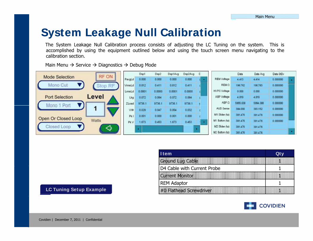
System Leakage Null CalibrationSystem Leakage Null CalibrationThe System Leakage Null Calibration process consists of adjusting the LC Tuning on the system This isThe System Leakage Null Calibration process consists of adjusting the LC Tuning on the system. This isaccomplished by using the equipment outlined below and using the touch screen menu navigating to thecalibration section.
Main Menu Service Diagnostics Debug Mode
Item QtyGround Lug Cable 1
LC Tuning Setup ExampleLC Tuning Setup Example
D4 Cable with Current Probe 1
Current Monitor 1
REM Adaptor 1
#0 Flathead Screwdriver 1
Covidien | December 7, 2011 | Confidential
Main Menu
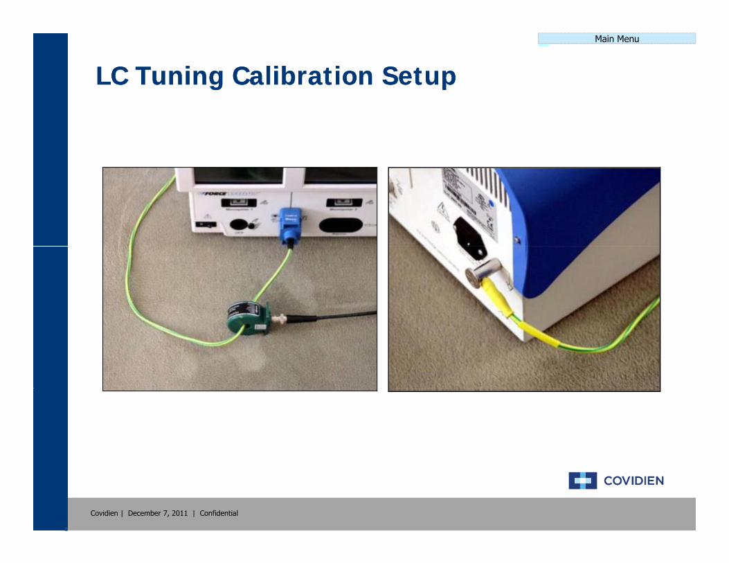
LC Tuning Calibration SetupLC Tuning Calibration Setup
Covidien | December 7, 2011 | Confidential

Main Menu
Utility CalibrationUtility CalibrationThe Utility Calibration process consists of setting up the date & time screen brightness touch screen andThe Utility Calibration process consists of setting up the date & time, screen brightness, touch screen, andscanners on the system. This is accomplished by using the equipment outlined below and using the touchscreen menu navigating to the calibration section.
TIME & DATE:Main Menu Setup Time And Datep
BRIGHTNESS, TOUCH SCREEN, & SCANNER:Main Menu Service Maintenance Calibrate Brightness
Touch ScreenScanner
Set Time & Date ExampleSet Time & Date Example
Brightness Setup ExampleBrightness Setup ExampleBrightness Setup ExampleBrightness Setup Example
Touch Screen Setup ExampleTouch Screen Setup Example
Scanner Setup ExampleScanner Setup Example
Item QtyStylus (Optional) 1
Ligasure 1 Dot Code Instrument 1
Covidien | December 7, 2011 | Confidential
Main Menu
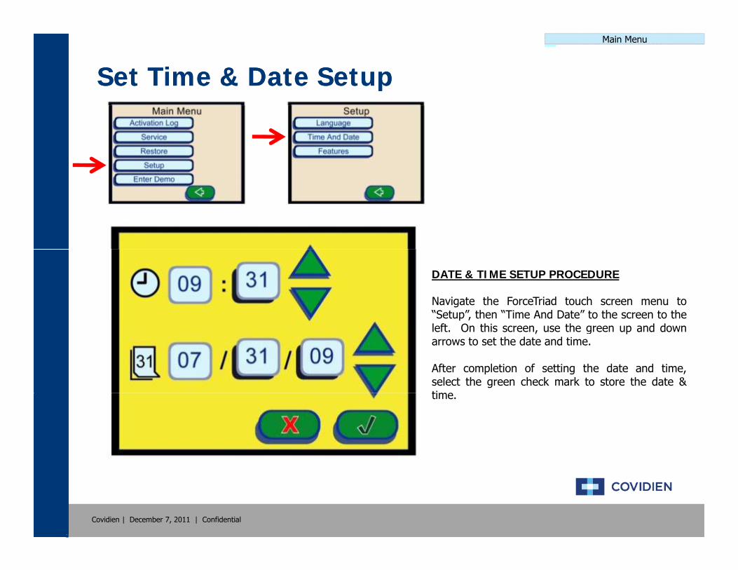
Set Time & Date SetupSet Time & Date Setup
DATE & TIME SETUP PROCEDURE
Navigate the ForceTriad touch screen menu to“Setup”, then “Time And Date” to the screen to theleft. On this screen, use the green up and downarrows to set the date and time.
After completion of setting the date and time,select the green check mark to store the date &timetime.
Covidien | December 7, 2011 | Confidential

Main Menu
Brightness Calibration SetupBrightness Calibration SetupHigh Intensity Low IntensityHigh Intensity Low Intensity
High Intensity Low Intensity Inactive Screeng y y
Covidien | December 7, 2011 | Confidential
Main Menu
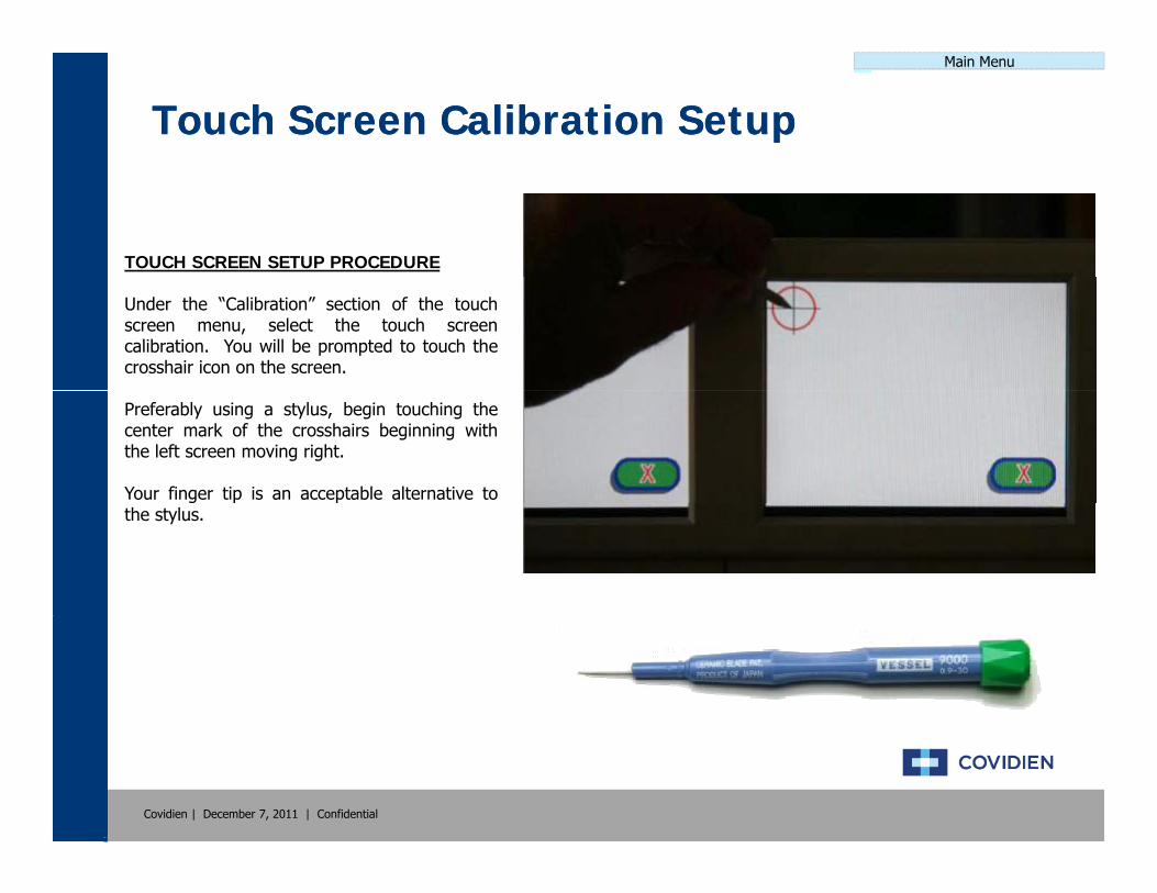
Touch Screen Calibration SetupTouch Screen Calibration Setup
TOUCH SCREEN SETUP PROCEDURE
Under the “Calibration” section of the touchscreen menu, select the touch screencalibration. You will be prompted to touch thecrosshair icon on the screen.
Preferably using a stylus, begin touching thecenter mark of the crosshairs beginning withthe left screen moving right.
Your finger tip is an acceptable alternative tog p pthe stylus.
Covidien | December 7, 2011 | Confidential
Main Menu
Scanner Calibration SetupScanner Calibration Setup
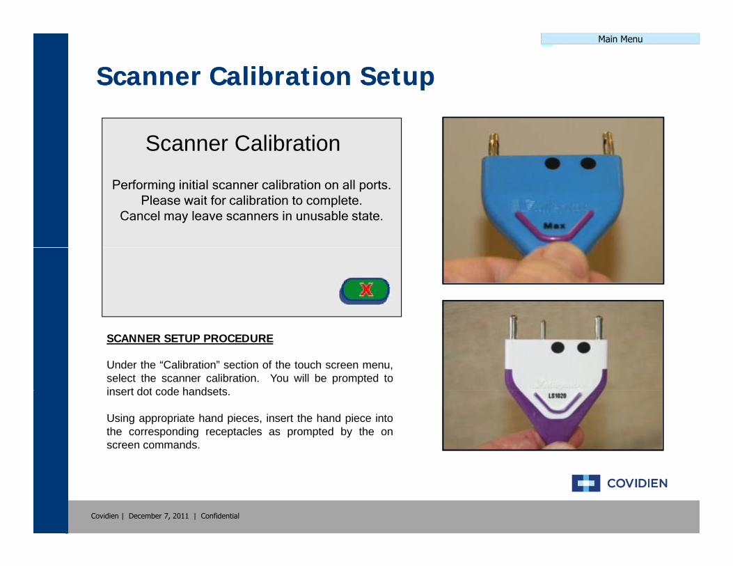
Scanner Calibration
Performing initial scanner calibration on all ports.Please wait for calibration to complete.
Cancel may leave scanners in unusable state.
SCANNER SETUP PROCEDURE
Under the “Calibration” section of the touch screen menu,select the scanner calibration. You will be prompted toinsert dot code handsetsinsert dot code handsets.
Using appropriate hand pieces, insert the hand piece intothe corresponding receptacles as prompted by the onscreen commands.
Covidien | December 7, 2011 | Confidential
Main Menu
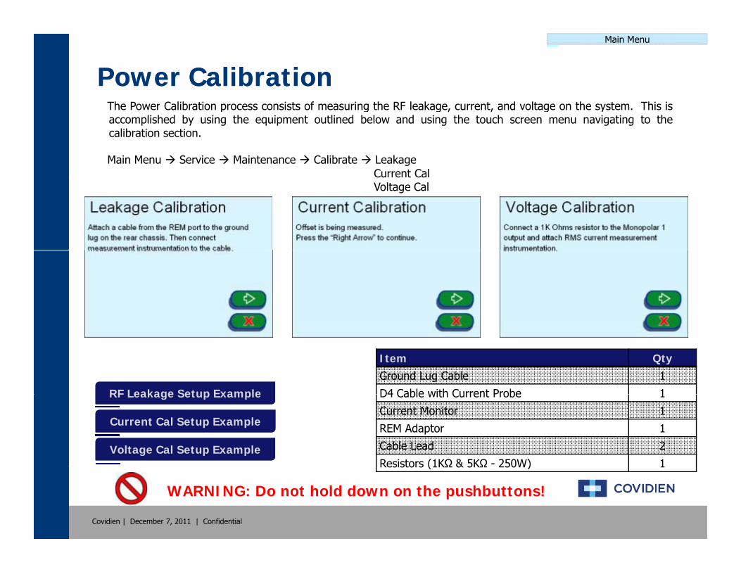
Power CalibrationPower CalibrationThe Power Calibration process consists of measuring the RF leakage current and voltage on the system This isThe Power Calibration process consists of measuring the RF leakage, current, and voltage on the system. This isaccomplished by using the equipment outlined below and using the touch screen menu navigating to thecalibration section.
Main Menu Service Maintenance Calibrate LeakageCurrent CalVoltage Cal
RF Leakage Setup ExampleRF Leakage Setup Example
Item QtyGround Lug Cable 1
D4 Cable with Current Probe 1RF Leakage Setup ExampleRF Leakage Setup Example
Current Cal Setup ExampleCurrent Cal Setup Example
Voltage Cal Setup ExampleVoltage Cal Setup Example
D4 Cable with Current Probe 1
Current Monitor 1
REM Adaptor 1
Cable Lead 2
Resistors (1KΩ & 5KΩ - 250W) 1
Covidien | December 7, 2011 | Confidential
WARNING: Do not hold down on the pushbuttons!
Resistors (1KΩ & 5KΩ 250W) 1

Main Menu
RF Leakage Calibration SetupRF Leakage Calibration Setup
Covidien | December 7, 2011 | Confidential
WARNING: Do not hold down on the pushbuttons!
Main Menu
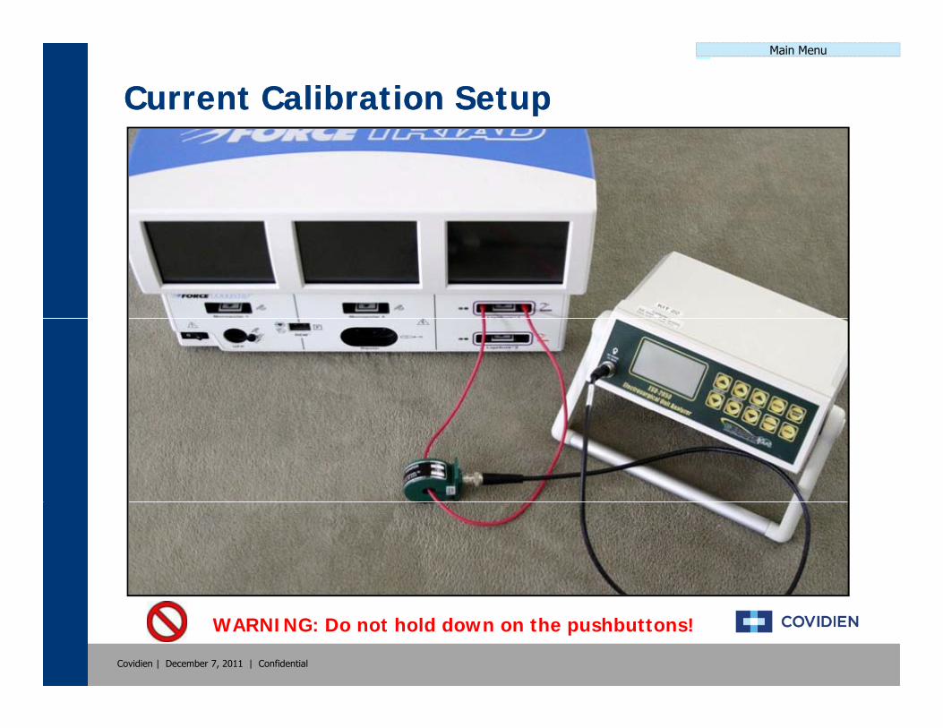
Current Calibration SetupCurrent Calibration Setup
Covidien | December 7, 2011 | Confidential
WARNING: Do not hold down on the pushbuttons!

Main Menu
Voltage Calibration SetupVoltage Calibration Setup
Covidien | December 7, 2011 | Confidential
WARNING: Do not hold down on the pushbuttons!
Main Menu
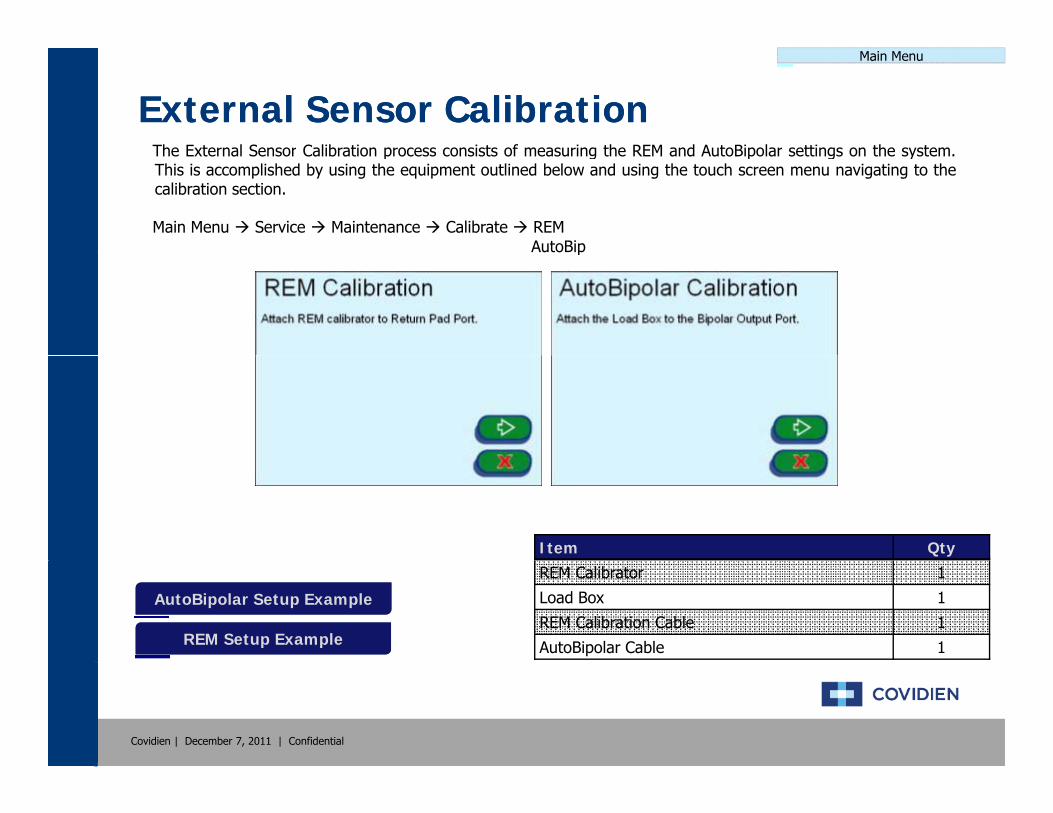
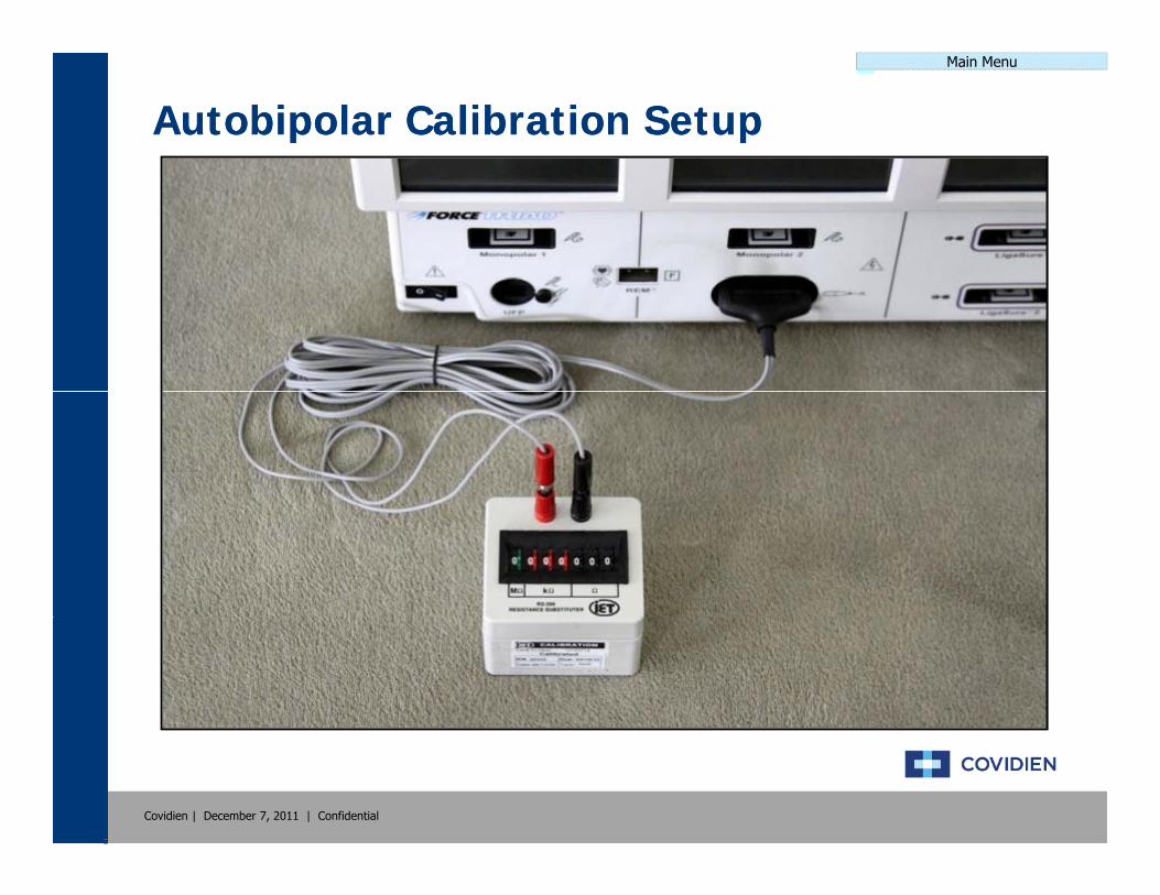
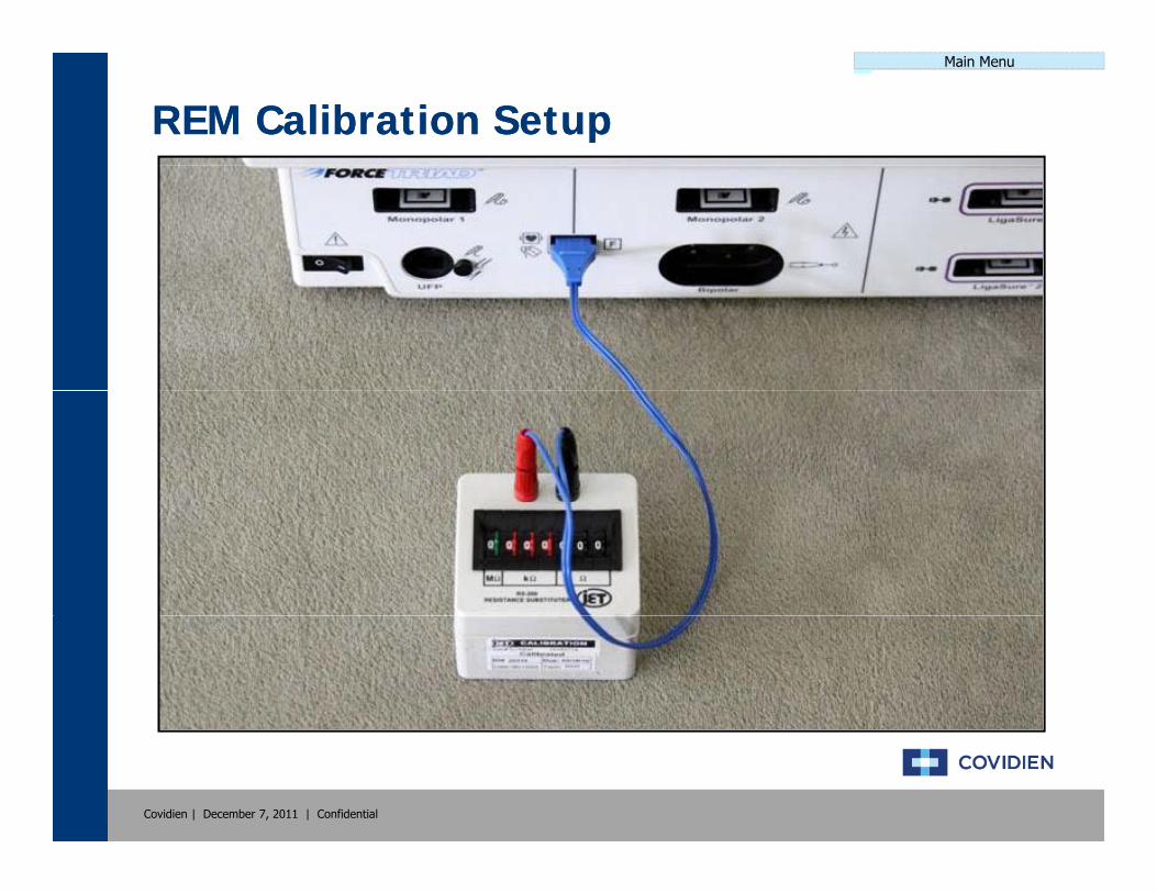
External Sensor CalibrationExternal Sensor CalibrationThe External Sensor Calibration process consists of measuring the REM and AutoBipolar settings on the systemThe External Sensor Calibration process consists of measuring the REM and AutoBipolar settings on the system.This is accomplished by using the equipment outlined below and using the touch screen menu navigating to thecalibration section.
Main Menu Service Maintenance Calibrate REMAutoBipp
Item Qty
AutoBipolar Setup ExampleAutoBipolar Setup Example
REM Setup ExampleREM Setup Example
REM Calibrator 1
Load Box 1
REM Calibration Cable 1
AutoBipolar Cable 1
Covidien | December 7, 2011 | Confidential
Main Menu
Autobipolar Calibration SetupAutobipolar Calibration Setup
Covidien | December 7, 2011 | Confidential
Main Menu
REM Calibration SetupREM Calibration Setup
Covidien | December 7, 2011 | Confidential
Main Menu
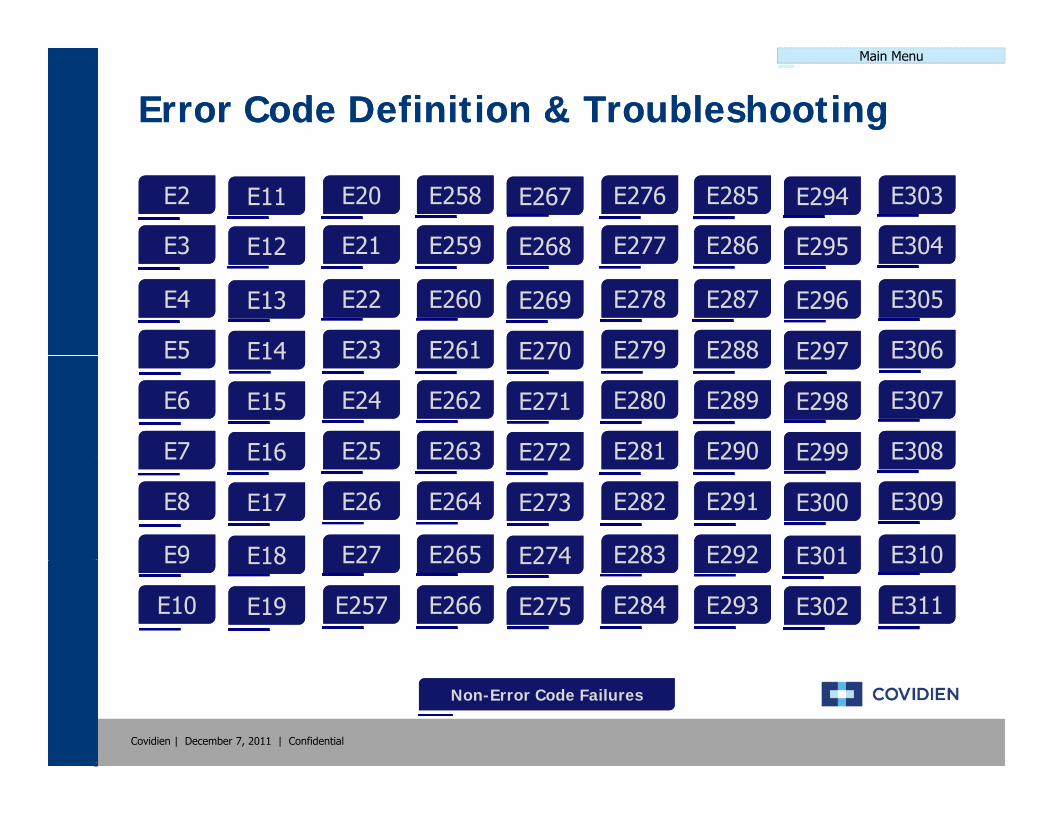
Error Code Definition & TroubleshootingError Code Definition & Troubleshooting
E2E2
E3E3
E11E11
E12E12
E20E20
E21E21
E258E258
E259E259
E267E267
E268E268
E276E276
E277E277
E285E285
E286E286
E294E294
E295E295
E303E303
E304E304E3E3
E4E4
E5E5
E12E12
E13E13
E14E14
E21E21
E22E22
E23E23
E259E259
E260E260
E261E261
E268E268
E269E269
E270E270
E277E277
E278E278
E279E279
E286E286
E287E287
E288E288
E295E295
E296E296
E297E297
E304E304
E305E305
E306E306E5E5
E6E6
E7E7
E14E14
E15E15
E16E16
E23E23
E24E24
E25E25
E261E261
E262E262
E263E263
E270E270
E271E271
E272E272
E279E279
E280E280
E281E281
E288E288
E289E289
E290E290
E297E297
E298E298
E299E299
E306E306
E307E307
E308E308E7E7
E8E8
E9E9
E16E16
E17E17
E18E18
E25E25
E26E26
E27E27
E263E263
E264E264
E265E265
E272E272
E273E273
E274E274
E281E281
E282E282
E283E283
E290E290
E291E291
E292E292
E299E299
E300E300
E301E301
E308E308
E309E309
E310E310E9E9
E10E10
E18E18
E19E19
E27E27
E257E257
E265E265
E266E266
E274E274
E275E275
E283E283
E284E284
E292E292
E293E293
E301E301
E302E302
E310E310
E311E311
Covidien | December 7, 2011 | Confidential
Non-Error Code FailuresNon-Error Code Failures

Main Menu
NonNon--Error Code TroubleshootingError Code Troubleshooting
Gray ScreensGray ScreensThe system responds to a power cycle and begins the system initiation. The three display screens show a blank, gray screen instead of displaying the white Covidien screen.
The system responds to a power cycle and begins the system initiation The threeBlack ScreensBlack Screens
Dark ScreensDark Screens
The system responds to a power cycle and begins the system initiation. The three display screens show a blank, black screen instead of displaying the white Covidien screen.
The system responds to a power cycle and begins the system initiation. The three display screens show a much darker screen of the expected white Covidien screen.Dark ScreensDark Screens
Flickering ScreensFlickering Screens
display screens show a much darker screen of the expected white Covidien screen. This can range from slightly darker to nearly unreadable.
The system responds to a power cycle and begins the system initiation. The screen and/or screens begin to flicker. The flickering can happen once or occur constantly.
No PowerNo Power
y
The system does not respond to a power cycle. The system displays and scanners do not illuminate.
User Self-Test ErrorUser Self-Test ErrorThe system initiates the self-test and may pass a portion of the testing. The unit then fails at some point during the self-test. The unit will generate an error but not an error code.
Covidien | December 7, 2011 | Confidential
Error Code FailuresError Code Failures

Main Menu
NonNon--Error Code Failures Error Code Failures -- Gray ScreensGray ScreensThe failures that are generated where thedisplays are blank and gray, there are a coupleof scenarios that could cause this. Typically,cables that are not connected or fullyconnected are the cause.
NON-COMPONENT ACTIONS1. Power cycling the system2. Inspecting the component cables
LEADING COMPONENT REPLACEMENTSLEADING COMPONENT REPLACEMENTS1. Ethernet Cable
• (Cable between Controller and Display)2. Steering Relay Cable
• (Cable between SR and Display)
NON-COMPONENT ACTIONS INSTRUCTION
1 P C l th it d ll th t t f th lf t t1. Power Cycle the unit and allow the system to perform the self-test.2. Remove the cover to the ForceTriad system and inspect the system
boards ensuring that the boards are properly seated within the unit and that all cables are also securely connected.
Covidien | December 7, 2011 | Confidential
Main Menu
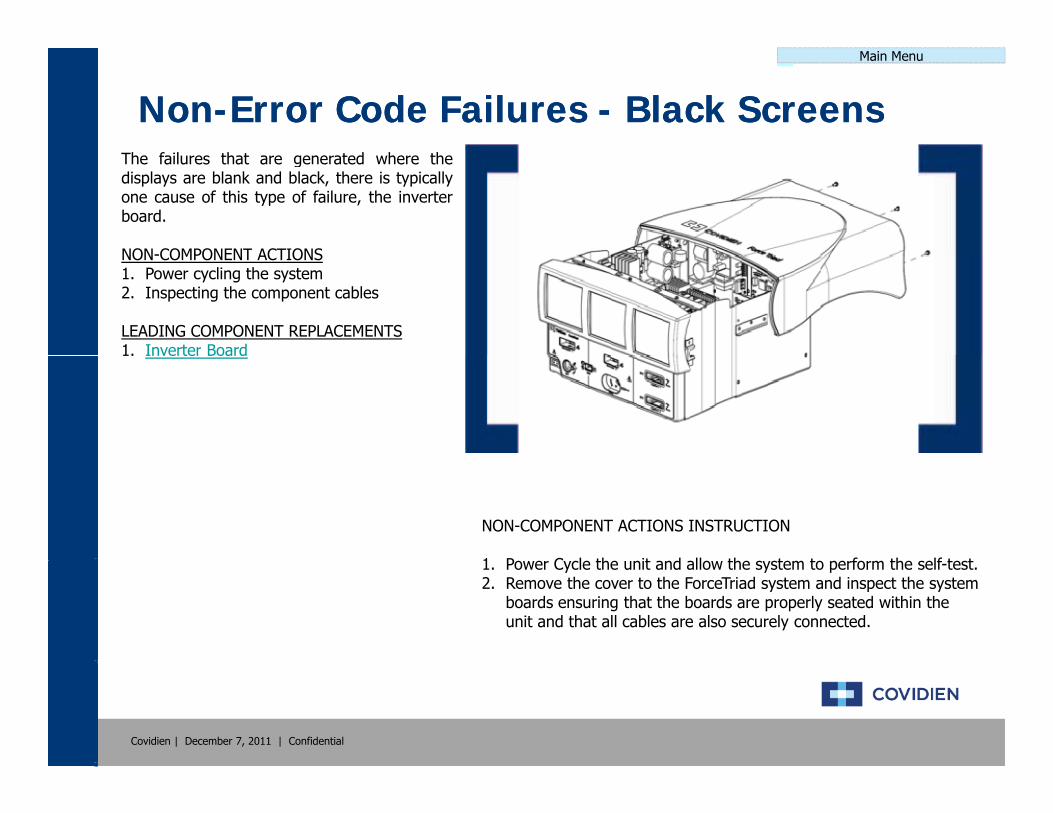
NonNon--Error Code Failures Error Code Failures -- Black ScreensBlack ScreensThe failures that are generated where thedisplays are blank and black, there is typicallyone cause of this type of failure, the inverterboard.
NON COMPONENT ACTIONSNON-COMPONENT ACTIONS1. Power cycling the system2. Inspecting the component cables
LEADING COMPONENT REPLACEMENTS1. Inverter Board1. Inverter Board
NON-COMPONENT ACTIONS INSTRUCTION
1 P C l th it d ll th t t f th lf t t1. Power Cycle the unit and allow the system to perform the self-test.2. Remove the cover to the ForceTriad system and inspect the system
boards ensuring that the boards are properly seated within the unit and that all cables are also securely connected.
Covidien | December 7, 2011 | Confidential
Main Menu
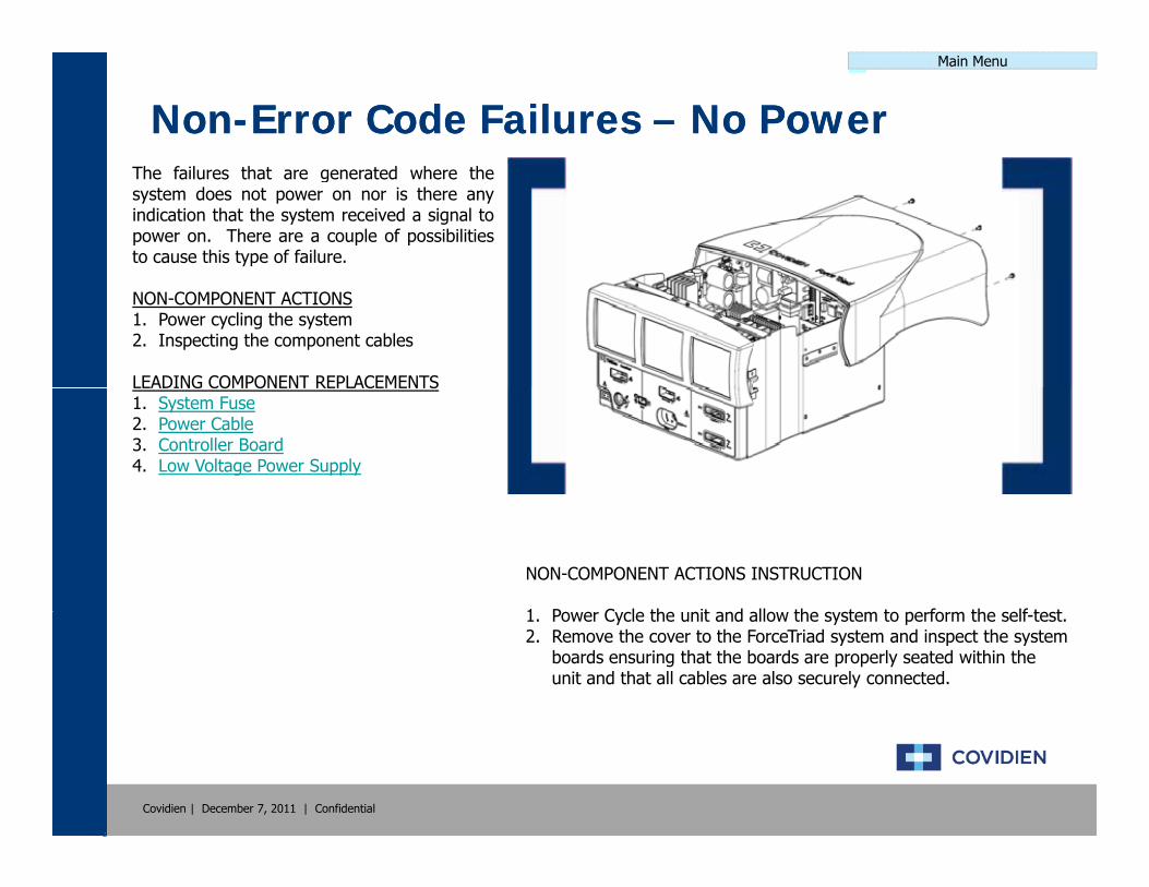
NonNon--Error Code Failures Error Code Failures –– No PowerNo PowerThe failures that are generated where thesystem does not power on nor is there anyindication that the system received a signal topower on. There are a couple of possibilitiesto cause this type of failure.
NON-COMPONENT ACTIONS1. Power cycling the system2. Inspecting the component cables
LEADING COMPONENT REPLACEMENTSLEADING COMPONENT REPLACEMENTS1. System Fuse2. Power Cable3. Controller Board4. Low Voltage Power Supply
NON-COMPONENT ACTIONS INSTRUCTION
1 P C l th it d ll th t t f th lf t t1. Power Cycle the unit and allow the system to perform the self-test.2. Remove the cover to the ForceTriad system and inspect the system
boards ensuring that the boards are properly seated within the unit and that all cables are also securely connected.
Covidien | December 7, 2011 | Confidential
Main Menu
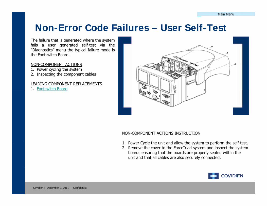
NonNon--Error Code Failures Error Code Failures –– User SelfUser Self--TestTestThe failure that is generated where the systemfails a user generated self-test via the“Diagnostics” menu the typical failure mode isthe Footswitch Board.
NON COMPONENT ACTIONSNON-COMPONENT ACTIONS1. Power cycling the system2. Inspecting the component cables
LEADING COMPONENT REPLACEMENTS1. Footswitch Board1. Footswitch Board
NON-COMPONENT ACTIONS INSTRUCTION
1 P C l th it d ll th t t f th lf t t1. Power Cycle the unit and allow the system to perform the self-test.2. Remove the cover to the ForceTriad system and inspect the system
boards ensuring that the boards are properly seated within the unit and that all cables are also securely connected.
Covidien | December 7, 2011 | Confidential

Main Menu
NonNon--Error Code Failures Error Code Failures –– Flickering ScreensFlickering ScreensThe failure that is generated where the systemfails a user generated self-test via the“Diagnostics” menu the typical failure mode isthe Footswitch Board.
NON COMPONENT ACTIONSNON-COMPONENT ACTIONS1. Power cycling the system2. Inspecting the component cables
LEADING COMPONENT REPLACEMENTS1. Power Cableo e Cab e
• (Cable between SR and Display)
NON-COMPONENT ACTIONS INSTRUCTION
1 P C l th it d ll th t t f th lf t t1. Power Cycle the unit and allow the system to perform the self-test.2. Remove the cover to the ForceTriad system and inspect the system
boards ensuring that the boards are properly seated within the unit and that all cables are also securely connected.
Covidien | December 7, 2011 | Confidential

Main Menu
NonNon--Error Code Failures Error Code Failures –– Dark ScreensDark ScreensThe failure that is generated where the systemfails a user generated self-test via the“Diagnostics” menu the typical failure mode isthe Footswitch Board.
NON COMPONENT ACTIONSNON-COMPONENT ACTIONS1. Power cycling the system2. Inspecting the component cables3. Brightness calibration
LEADING COMPONENT REPLACEMENTSG CO O C S1. Display Inverter
NON-COMPONENT ACTIONS INSTRUCTION
1 P C l th it d ll th t t f th lf t t1. Power Cycle the unit and allow the system to perform the self-test.2. Remove the cover to the ForceTriad system and inspect the system
boards ensuring that the boards are properly seated within the unit and that all cables are also securely connected.
3. Perform a brightness calibration as outlined in the Service Manual.
Covidien | December 7, 2011 | Confidential
Main Menu
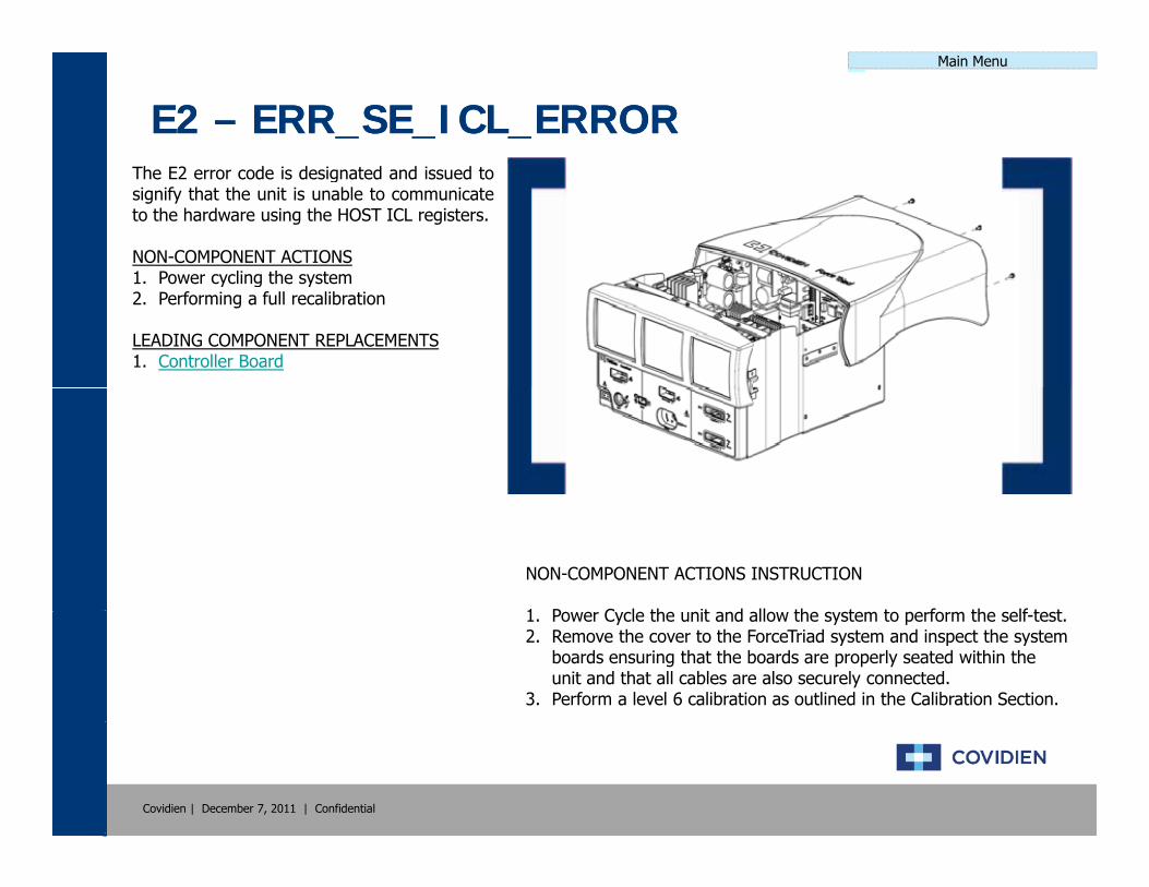
E2 E2 –– ERR_SE_ICL_ERRORERR_SE_ICL_ERRORThe E2 error code is designated and issued tosignify that the unit is unable to communicateto the hardware using the HOST ICL registers.
NON-COMPONENT ACTIONS1 Power cycling the system1. Power cycling the system2. Performing a full recalibration
LEADING COMPONENT REPLACEMENTS1. Controller Board
NON-COMPONENT ACTIONS INSTRUCTION
1 P C l th it d ll th t t f th lf t t1. Power Cycle the unit and allow the system to perform the self-test.2. Remove the cover to the ForceTriad system and inspect the system
boards ensuring that the boards are properly seated within the unit and that all cables are also securely connected.
3. Perform a level 6 calibration as outlined in the Calibration Section.
Covidien | December 7, 2011 | Confidential

Main Menu
E3 E3 –– ERR_SE_APP_ROM_FAILERR_SE_APP_ROM_FAILThe E3 error code is designated and issued tosignify that the DSP application ROM checkfailed during start-up.
NON-COMPONENT ACTIONS1 Power cycling the system1. Power cycling the system2. Performing a full recalibration
LEADING COMPONENT REPLACEMENTS1. Controller Board
NON-COMPONENT ACTIONS INSTRUCTION
1 P C l th it d ll th t t f th lf t t1. Power Cycle the unit and allow the system to perform the self-test.2. Remove the cover to the ForceTriad system and inspect the system
boards ensuring that the boards are properly seated within the unit and that all cables are also securely connected.
3. Perform a level 6 calibration as outlined in the Calibration Section.
Covidien | December 7, 2011 | Confidential

Main Menu
E4 E4 –– ERR_SE_BOOT_ROM_FAILERR_SE_BOOT_ROM_FAILThe E4 error code is designated and issued tosignify that the DSP boot ROM check failedduring start-up.
NON-COMPONENT ACTIONS1 Power cycling the system1. Power cycling the system2. Performing a full recalibration
LEADING COMPONENT REPLACEMENTS1. Controller Board
NON-COMPONENT ACTIONS INSTRUCTION
1 P C l th it d ll th t t f th lf t t1. Power Cycle the unit and allow the system to perform the self-test.2. Remove the cover to the ForceTriad system and inspect the system
boards ensuring that the boards are properly seated within the unit and that all cables are also securely connected.
3. Perform a level 6 calibration as outlined in the Calibration Section.
Covidien | December 7, 2011 | Confidential

Main Menu
E5 E5 -- ERR_SE_RAM_FAILERR_SE_RAM_FAILThe E5 error code is designated and issued tosignify that the DSP RAM check failed duringstart-up.
NON-COMPONENT ACTIONS1 Power cycling the system1. Power cycling the system2. Performing a full recalibration
LEADING COMPONENT REPLACEMENTS1. Controller Board
NON-COMPONENT ACTIONS INSTRUCTION
1 P C l th it d ll th t t f th lf t t1. Power Cycle the unit and allow the system to perform the self-test.2. Remove the cover to the ForceTriad system and inspect the system
boards ensuring that the boards are properly seated within the unit and that all cables are also securely connected.
3. Perform a level 6 calibration as outlined in the Calibration Section.
Covidien | December 7, 2011 | Confidential

Main Menu
E6 E6 –– ERR_SE_RTOS_FAILERR_SE_RTOS_FAILThe E6 error code is designated and issued tosignify that a software error has occurred.The E6 error code is typically issued duringreal time to signify an operating system error.
NON COMPONENT ACTIONSNON-COMPONENT ACTIONS1. Power cycling the system2. Performing a full recalibration
LEADING COMPONENT REPLACEMENTS1. Controller Board1. Controller Board2. System Display
NON-COMPONENT ACTIONS INSTRUCTION
1 P C l th it d ll th t t f th lf t t1. Power Cycle the unit and allow the system to perform the self-test.2. Remove the cover to the ForceTriad system and inspect the system
boards ensuring that the boards are properly seated within the unit and that all cables are also securely connected.
3. Perform a level 6 calibration as outlined in the Calibration Section.
Covidien | December 7, 2011 | Confidential
Main Menu
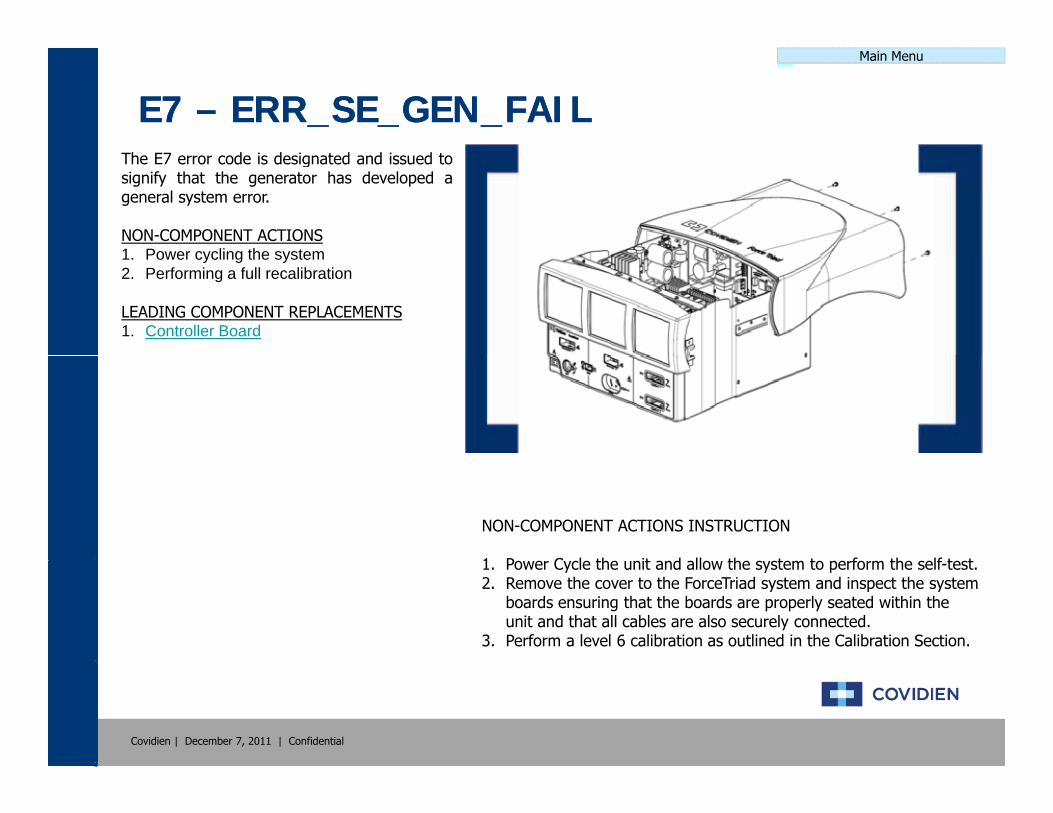
E7 E7 –– ERR_SE_GEN_FAILERR_SE_GEN_FAILThe E7 error code is designated and issued tosignify that the generator has developed ageneral system error.
NON-COMPONENT ACTIONS1 Power cycling the system1. Power cycling the system2. Performing a full recalibration
LEADING COMPONENT REPLACEMENTS1. Controller Board
NON-COMPONENT ACTIONS INSTRUCTION
1 P C l th it d ll th t t f th lf t t1. Power Cycle the unit and allow the system to perform the self-test.2. Remove the cover to the ForceTriad system and inspect the system
boards ensuring that the boards are properly seated within the unit and that all cables are also securely connected.
3. Perform a level 6 calibration as outlined in the Calibration Section.
Covidien | December 7, 2011 | Confidential

Main Menu
E8 E8 -- ERR_SE_CRITICAL_DATAERR_SE_CRITICAL_DATAThe E8 error code is designated and issued tosignify that the system has a software errorcaused by a corrupt data string.
NON-COMPONENT ACTIONS1 Power cycling the system1. Power cycling the system2. Performing a full recalibration
LEADING COMPONENT REPLACEMENTS1. Controller Board
NON-COMPONENT ACTIONS INSTRUCTION
1 P C l th it d ll th t t f th lf t t1. Power Cycle the unit and allow the system to perform the self-test.2. Remove the cover to the ForceTriad system and inspect the system
boards ensuring that the boards are properly seated within the unit and that all cables are also securely connected.
3. Perform a level 6 calibration as outlined in the Calibration Section.
Covidien | December 7, 2011 | Confidential
Main Menu
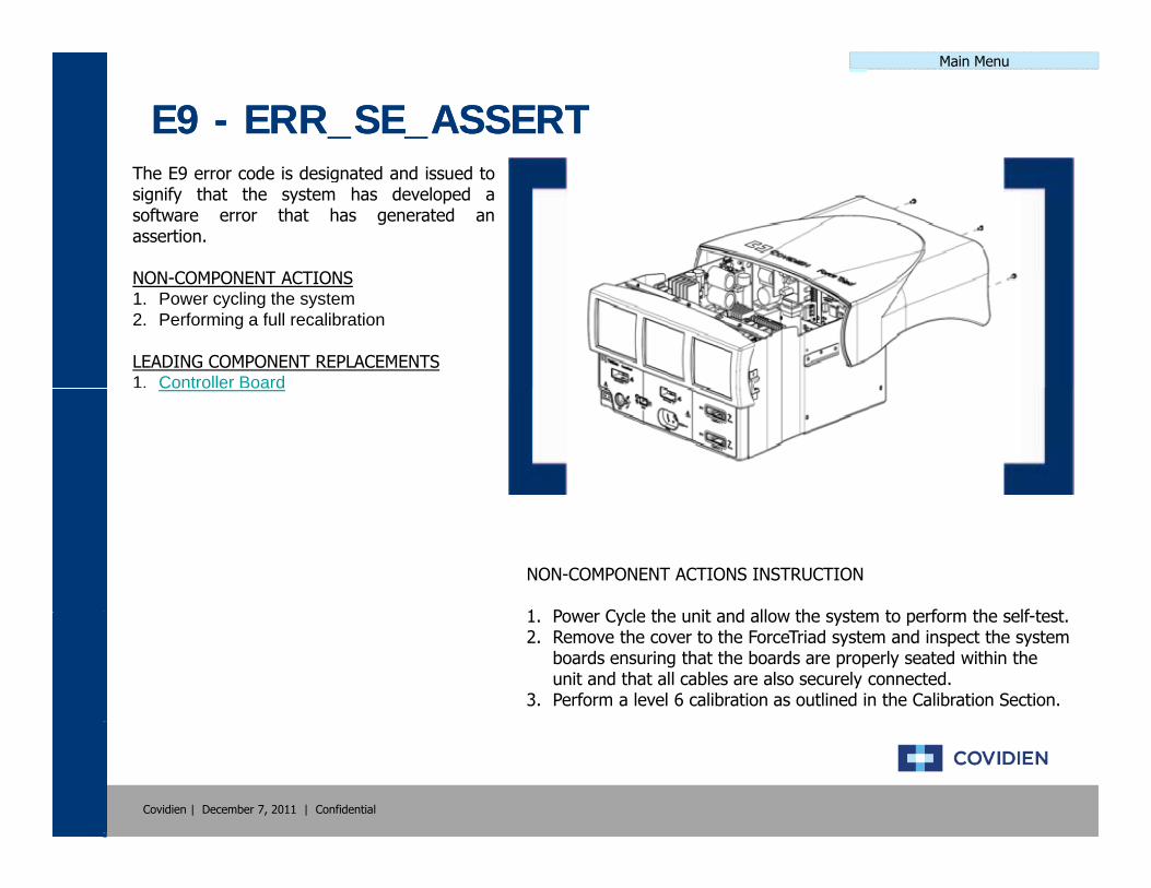
E9 E9 -- ERR_SE_ASSERTERR_SE_ASSERTThe E9 error code is designated and issued tosignify that the system has developed asoftware error that has generated anassertion.
NON COMPONENT ACTIONSNON-COMPONENT ACTIONS1. Power cycling the system2. Performing a full recalibration
LEADING COMPONENT REPLACEMENTS1. Controller BoardCo t o e oa d
NON-COMPONENT ACTIONS INSTRUCTION
1 P C l th it d ll th t t f th lf t t1. Power Cycle the unit and allow the system to perform the self-test.2. Remove the cover to the ForceTriad system and inspect the system
boards ensuring that the boards are properly seated within the unit and that all cables are also securely connected.
3. Perform a level 6 calibration as outlined in the Calibration Section.
Covidien | December 7, 2011 | Confidential

Main Menu
E10 E10 -- ERR_SE_INVALID_DATAERR_SE_INVALID_DATAThe E10 error code is designated and issuedto signify that a software failure occurredbecause of an invalid data string.
NON-COMPONENT ACTIONS1 Power cycling the system1. Power cycling the system2. Performing a full recalibration
LEADING COMPONENT REPLACEMENTS1. Controller Board
NON-COMPONENT ACTIONS INSTRUCTION
1 P C l th it d ll th t t f th lf t t1. Power Cycle the unit and allow the system to perform the self-test.2. Remove the cover to the ForceTriad system and inspect the system
boards ensuring that the boards are properly seated within the unit and that all cables are also securely connected.
3. Perform a level 6 calibration as outlined in the Calibration Section.
Covidien | December 7, 2011 | Confidential

Main Menu
E11 E11 -- ERR_SE_MACHINE_CHECK_EXCEPTIONERR_SE_MACHINE_CHECK_EXCEPTIONThe E11 error code is designated and issuedto signify that a HOST processor machinecheck exception has occurred.
NON-COMPONENT ACTIONS1 Power cycling the system1. Power cycling the system2. Performing a full recalibration
LEADING COMPONENT REPLACEMENTS1. Controller Board
NON-COMPONENT ACTIONS INSTRUCTION
1 P C l th it d ll th t t f th lf t t1. Power Cycle the unit and allow the system to perform the self-test.2. Remove the cover to the ForceTriad system and inspect the system
boards ensuring that the boards are properly seated within the unit and that all cables are also securely connected.
3. Perform a level 6 calibration as outlined in the Calibration Section.
Covidien | December 7, 2011 | Confidential

Main Menu
E12 E12 -- ERR_SE_DATA_STORAGE_EXCEPTIONERR_SE_DATA_STORAGE_EXCEPTIONThe E12 error code is designated and issuedto signify that a HOST processor data storageexception has occurred.
NON-COMPONENT ACTIONS1 Power cycling the system1. Power cycling the system2. Performing a full recalibration
LEADING COMPONENT REPLACEMENTS1. Controller Board
NON-COMPONENT ACTIONS INSTRUCTION
1 P C l th it d ll th t t f th lf t t1. Power Cycle the unit and allow the system to perform the self-test.2. Remove the cover to the ForceTriad system and inspect the system
boards ensuring that the boards are properly seated within the unit and that all cables are also securely connected.
3. Perform a level 6 calibration as outlined in the Calibration Section.
Covidien | December 7, 2011 | Confidential

Main Menu
E13 E13 -- ERR_SE_ISI_EXCEPTIONERR_SE_ISI_EXCEPTIONThe E13 error code is designated and issuedto signify that a HOST processor data storageexception has occurred.
NON-COMPONENT ACTIONS1 Power cycling the system1. Power cycling the system2. Performing a full recalibration
LEADING COMPONENT REPLACEMENTS1. Controller Board
NON-COMPONENT ACTIONS INSTRUCTION
1 P C l th it d ll th t t f th lf t t1. Power Cycle the unit and allow the system to perform the self-test.2. Remove the cover to the ForceTriad system and inspect the system
boards ensuring that the boards are properly seated within the unit and that all cables are also securely connected.
3. Perform a level 6 calibration as outlined in the Calibration Section.
Covidien | December 7, 2011 | Confidential

Main Menu
E14 E14 -- ERR_SE_ALIGNMENT_EXCEPTIONERR_SE_ALIGNMENT_EXCEPTIONThe E14 error code is designated and issuedto signify that a HOST processor alignmentexception has occurred.
NON-COMPONENT ACTIONS1 Power cycling the system1. Power cycling the system2. Performing a full recalibration
LEADING COMPONENT REPLACEMENTS1. Controller Board
NON-COMPONENT ACTIONS INSTRUCTION
1 P C l th it d ll th t t f th lf t t1. Power Cycle the unit and allow the system to perform the self-test.2. Remove the cover to the ForceTriad system and inspect the system
boards ensuring that the boards are properly seated within the unit and that all cables are also securely connected.
3. Perform a level 6 calibration as outlined in the Calibration Section.
Covidien | December 7, 2011 | Confidential
Main Menu
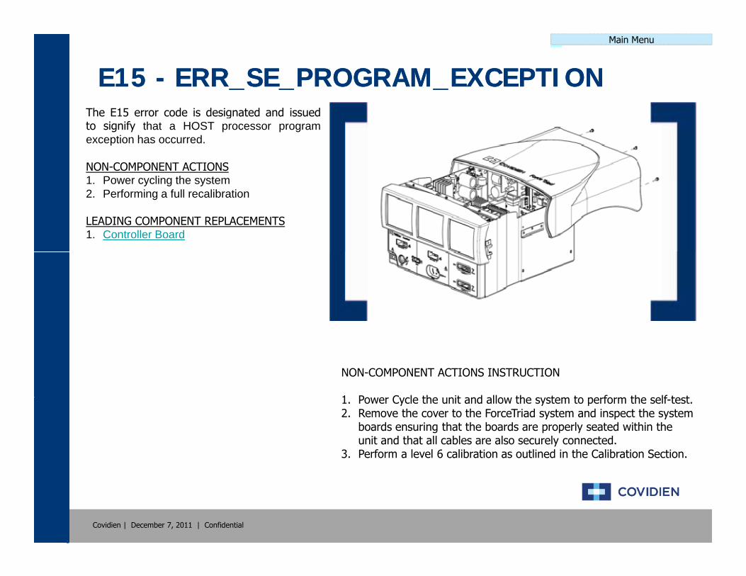
E15 E15 -- ERR_SE_PROGRAM_EXCEPTIONERR_SE_PROGRAM_EXCEPTIONThe E15 error code is designated and issuedto signify that a HOST processor programexception has occurred.
NON-COMPONENT ACTIONS1 Power cycling the system1. Power cycling the system2. Performing a full recalibration
LEADING COMPONENT REPLACEMENTS1. Controller Board
NON-COMPONENT ACTIONS INSTRUCTION
1 P C l th it d ll th t t f th lf t t1. Power Cycle the unit and allow the system to perform the self-test.2. Remove the cover to the ForceTriad system and inspect the system
boards ensuring that the boards are properly seated within the unit and that all cables are also securely connected.
3. Perform a level 6 calibration as outlined in the Calibration Section.
Covidien | December 7, 2011 | Confidential

Main Menu
E16 E16 -- ERR_SE_FP_UNAVAILABLE_EXCEPTIONERR_SE_FP_UNAVAILABLE_EXCEPTIONThe E16 error code is designated and issuedto signify that a HOST processor floating pointunavailable exception has occurred.
NON-COMPONENT ACTIONS1 Power cycling the system1. Power cycling the system2. Performing a full recalibration
LEADING COMPONENT REPLACEMENTS1. Controller Board
NON-COMPONENT ACTIONS INSTRUCTION
1 P C l th it d ll th t t f th lf t t1. Power Cycle the unit and allow the system to perform the self-test.2. Remove the cover to the ForceTriad system and inspect the system
boards ensuring that the boards are properly seated within the unit and that all cables are also securely connected.
3. Perform a level 6 calibration as outlined in the Calibration Section.
Covidien | December 7, 2011 | Confidential
Main Menu
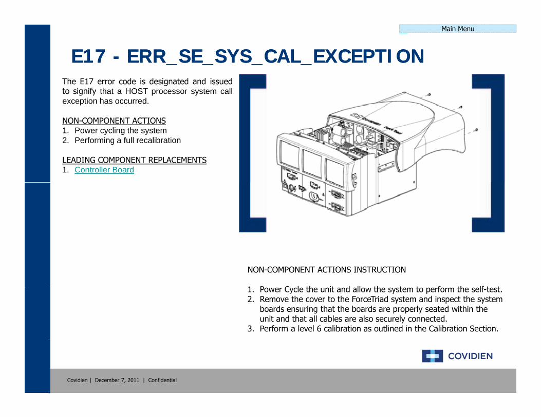
E17 E17 -- ERR_SE_SYS_CAL_EXCEPTIONERR_SE_SYS_CAL_EXCEPTIONThe E17 error code is designated and issuedto signify that a HOST processor system callexception has occurred.
NON-COMPONENT ACTIONS1 Power cycling the system1. Power cycling the system2. Performing a full recalibration
LEADING COMPONENT REPLACEMENTS1. Controller Board
NON-COMPONENT ACTIONS INSTRUCTION
1 P C l th it d ll th t t f th lf t t1. Power Cycle the unit and allow the system to perform the self-test.2. Remove the cover to the ForceTriad system and inspect the system
boards ensuring that the boards are properly seated within the unit and that all cables are also securely connected.
3. Perform a level 6 calibration as outlined in the Calibration Section.
Covidien | December 7, 2011 | Confidential

Main Menu
E18 E18 -- ERR_SE_TRACE_EXCEPTIONERR_SE_TRACE_EXCEPTIONThe E18 error code is designated and issuedto signify that a HOST processor traceexception has occurred.
NON-COMPONENT ACTIONS1 Power cycling the system1. Power cycling the system2. Performing a full recalibration
LEADING COMPONENT REPLACEMENTS1. Controller Board
NON-COMPONENT ACTIONS INSTRUCTION
1 P C l th it d ll th t t f th lf t t1. Power Cycle the unit and allow the system to perform the self-test.2. Remove the cover to the ForceTriad system and inspect the system
boards ensuring that the boards are properly seated within the unit and that all cables are also securely connected.
3. Perform a level 6 calibration as outlined in the Calibration Section.
Covidien | December 7, 2011 | Confidential

Main Menu
E19 E19 -- ERR_FP_ASSIST_EXCEPTIONERR_FP_ASSIST_EXCEPTIONThe E19 error code is designated and issuedto signify that a HOST processor floating pointassist exception has occurred.
NON-COMPONENT ACTIONS1 Power cycling the system1. Power cycling the system2. Performing a full recalibration
LEADING COMPONENT REPLACEMENTS1. Controller Board
NON-COMPONENT ACTIONS INSTRUCTION
1 P C l th it d ll th t t f th lf t t1. Power Cycle the unit and allow the system to perform the self-test.2. Remove the cover to the ForceTriad system and inspect the system
boards ensuring that the boards are properly seated within the unit and that all cables are also securely connected.
3. Perform a level 6 calibration as outlined in the Calibration Section.
Covidien | December 7, 2011 | Confidential

Main Menu
E20 E20 -- ERR_SE_MEM_ALLOC_FAILERR_SE_MEM_ALLOC_FAILThe E20 error code is designated and issuedto signify that a memory allocation failurewithin the unit has occurred.
NON-COMPONENT ACTIONS1 Power cycling the system1. Power cycling the system2. Performing a full recalibration
LEADING COMPONENT REPLACEMENTS1. Controller Board
NON-COMPONENT ACTIONS INSTRUCTION
1 P C l th it d ll th t t f th lf t t1. Power Cycle the unit and allow the system to perform the self-test.2. Remove the cover to the ForceTriad system and inspect the system
boards ensuring that the boards are properly seated within the unit and that all cables are also securely connected.
3. Perform a level 6 calibration as outlined in the Calibration Section.
Covidien | December 7, 2011 | Confidential

Main Menu
E21 E21 -- ERR_SE_UNKNOWN_EXCEPTIONERR_SE_UNKNOWN_EXCEPTIONThe E21 error code is designated and issuedto signify that a HOST processor hasgenerated an unknown exception and that theexception vector is not a valid vector.
NON COMPONENT ACTIONSNON-COMPONENT ACTIONS1. Power cycling the system2. Performing a full recalibration
LEADING COMPONENT REPLACEMENTS1. Controller BoardCo t o e oa d
NON-COMPONENT ACTIONS INSTRUCTION
1 P C l th it d ll th t t f th lf t t1. Power Cycle the unit and allow the system to perform the self-test.2. Remove the cover to the ForceTriad system and inspect the system
boards ensuring that the boards are properly seated within the unit and that all cables are also securely connected.
3. Perform a level 6 calibration as outlined in the Calibration Section.
Covidien | December 7, 2011 | Confidential

Main Menu
E22 E22 -- ERR_SE_UNKNOWN_INTERRUPTERR_SE_UNKNOWN_INTERRUPTThe E22 error code is designated and issuedto signify that a HOST processor has receivedan interrupt that is not initialized.
NON-COMPONENT ACTIONS1 Power cycling the system1. Power cycling the system2. Performing a full recalibration
LEADING COMPONENT REPLACEMENTS1. Controller Board
NON-COMPONENT ACTIONS INSTRUCTION
1 P C l th it d ll th t t f th lf t t1. Power Cycle the unit and allow the system to perform the self-test.2. Remove the cover to the ForceTriad system and inspect the system
boards ensuring that the boards are properly seated within the unit and that all cables are also securely connected.
3. Perform a level 6 calibration as outlined in the Calibration Section.
Covidien | December 7, 2011 | Confidential

Main Menu
E23 E23 -- ERR_SE_STACK_OVERFLOWERR_SE_STACK_OVERFLOWThe E23 error code is designated and issuedto signify that a thread on the HOST hasoverflowed its stack.
NON-COMPONENT ACTIONS1 Power cycling the system1. Power cycling the system2. Performing a full recalibration
LEADING COMPONENT REPLACEMENTS1. Controller Board
NON-COMPONENT ACTIONS INSTRUCTION
1 P C l th it d ll th t t f th lf t t1. Power Cycle the unit and allow the system to perform the self-test.2. Remove the cover to the ForceTriad system and inspect the system
boards ensuring that the boards are properly seated within the unit and that all cables are also securely connected.
3. Perform a level 6 calibration as outlined in the Calibration Section.
Covidien | December 7, 2011 | Confidential

Main Menu
E24 E24 -- ERR_SE_DMA_FAILUREERR_SE_DMA_FAILUREThe E24 error code is designated and issuedto signify that the iDMA is stuck.
NON-COMPONENT ACTIONS1. Power cycling the system2 Performing a full recalibration2. Performing a full recalibration
LEADING COMPONENT REPLACEMENTS1. Controller Board
NON-COMPONENT ACTIONS INSTRUCTION
1 P C l th it d ll th t t f th lf t t1. Power Cycle the unit and allow the system to perform the self-test.2. Remove the cover to the ForceTriad system and inspect the system
boards ensuring that the boards are properly seated within the unit and that all cables are also securely connected.
3. Perform a level 6 calibration as outlined in the Calibration Section.
Covidien | December 7, 2011 | Confidential

Main Menu
E25 E25 -- ERR_SE_UNHANDLED_INTERRUPTERR_SE_UNHANDLED_INTERRUPTThe E25 error code is designated and issuedto signify that a HOST processor has receivedan interrupt that it does not how to handle..
NON-COMPONENT ACTIONS1 Power cycling the system1. Power cycling the system2. Performing a full recalibration
LEADING COMPONENT REPLACEMENTS1. Controller Board
NON-COMPONENT ACTIONS INSTRUCTION
1 P C l th it d ll th t t f th lf t t1. Power Cycle the unit and allow the system to perform the self-test.2. Remove the cover to the ForceTriad system and inspect the system
boards ensuring that the boards are properly seated within the unit and that all cables are also securely connected.
3. Perform a level 6 calibration as outlined in the Calibration Section.
Covidien | December 7, 2011 | Confidential
Main Menu
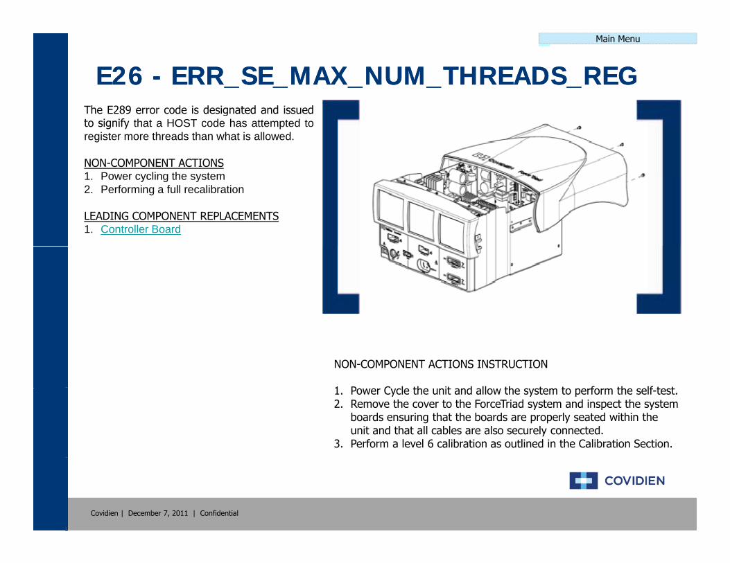
E26 E26 -- ERR_SE_MAX_NUM_THREADS_REGERR_SE_MAX_NUM_THREADS_REGThe E289 error code is designated and issuedto signify that a HOST code has attempted toregister more threads than what is allowed.
NON-COMPONENT ACTIONS1 Power cycling the system1. Power cycling the system2. Performing a full recalibration
LEADING COMPONENT REPLACEMENTS1. Controller Board
NON-COMPONENT ACTIONS INSTRUCTION
1 P C l th it d ll th t t f th lf t t1. Power Cycle the unit and allow the system to perform the self-test.2. Remove the cover to the ForceTriad system and inspect the system
boards ensuring that the boards are properly seated within the unit and that all cables are also securely connected.
3. Perform a level 6 calibration as outlined in the Calibration Section.
Covidien | December 7, 2011 | Confidential

Main Menu
E27 E27 -- ERR_SE_NULL_POINTERERR_SE_NULL_POINTERThe E27 error code is designated and issuedto signify that a HOST code has detected apointer that has a NULL value.
NON-COMPONENT ACTIONS1 Power cycling the system1. Power cycling the system2. Performing a full recalibration
LEADING COMPONENT REPLACEMENTS1. Controller Board
NON-COMPONENT ACTIONS INSTRUCTION
1 P C l th it d ll th t t f th lf t t1. Power Cycle the unit and allow the system to perform the self-test.2. Remove the cover to the ForceTriad system and inspect the system
boards ensuring that the boards are properly seated within the unit and that all cables are also securely connected.
3. Perform a level 6 calibration as outlined in the Calibration Section.
Covidien | December 7, 2011 | Confidential

Main Menu
E257 E257 -- ERR_NR_DOSAGEERR_NR_DOSAGEThe E257 error code is designated and issuedto signify that the system has a general RFdosage error.
NON-COMPONENT ACTIONS1 Power cycling the system1. Power cycling the system2. Performing a full recalibration
LEADING COMPONENT REPLACEMENTS1. Controller Board2. RF Board2. RF Board
NON-COMPONENT ACTIONS INSTRUCTION
1 P C l th it d ll th t t f th lf t t1. Power Cycle the unit and allow the system to perform the self-test.2. Remove the cover to the ForceTriad system and inspect the system
boards ensuring that the boards are properly seated within the unit and that all cables are also securely connected.
3. Perform a level 6 calibration as outlined in the Calibration Section.
Covidien | December 7, 2011 | Confidential

Main Menu
E258 E258 -- ERR_NR_MEM_ALLOC_FAILERR_NR_MEM_ALLOC_FAILThe E258 error code is designated and issuedto signify that the system has generated amemory allocation software error.
NON-COMPONENT ACTIONS1 Power cycling the system1. Power cycling the system2. Performing a full recalibration
LEADING COMPONENT REPLACEMENTS1. Controller Board
NON-COMPONENT ACTIONS INSTRUCTION
1 P C l th it d ll th t t f th lf t t1. Power Cycle the unit and allow the system to perform the self-test.2. Remove the cover to the ForceTriad system and inspect the system
boards ensuring that the boards are properly seated within the unit and that all cables are also securely connected.
3. Perform a level 6 calibration as outlined in the Calibration Section.
Covidien | December 7, 2011 | Confidential
Main Menu
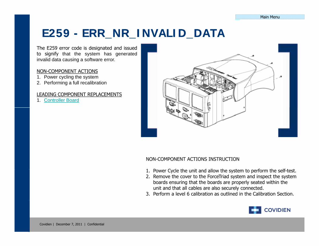
E259 E259 -- ERR_NR_INVALID_DATAERR_NR_INVALID_DATAThe E259 error code is designated and issuedto signify that the system has generatedinvalid data causing a software error.
NON-COMPONENT ACTIONS1 Power cycling the system1. Power cycling the system2. Performing a full recalibration
LEADING COMPONENT REPLACEMENTS1. Controller Board
NON-COMPONENT ACTIONS INSTRUCTION
1 P C l th it d ll th t t f th lf t t1. Power Cycle the unit and allow the system to perform the self-test.2. Remove the cover to the ForceTriad system and inspect the system
boards ensuring that the boards are properly seated within the unit and that all cables are also securely connected.
3. Perform a level 6 calibration as outlined in the Calibration Section.
Covidien | December 7, 2011 | Confidential
Main Menu
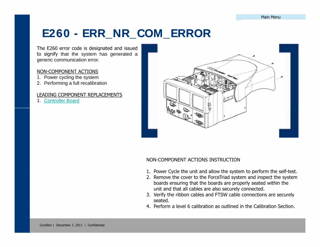
E260 E260 -- ERR_NR_COM_ERRORERR_NR_COM_ERRORThe E260 error code is designated and issuedto signify that the system has generated ageneric communication error.
NON-COMPONENT ACTIONS1 Power cycling the system1. Power cycling the system2. Performing a full recalibration
LEADING COMPONENT REPLACEMENTS1. Controller Board
NON-COMPONENT ACTIONS INSTRUCTION
1 P C l th it d ll th t t f th lf t t1. Power Cycle the unit and allow the system to perform the self-test.2. Remove the cover to the ForceTriad system and inspect the system
boards ensuring that the boards are properly seated within the unit and that all cables are also securely connected.
3. Verify the ribbon cables and FTSW cable connections are securely seated
Covidien | December 7, 2011 | Confidential
seated.4. Perform a level 6 calibration as outlined in the Calibration Section.

Main Menu
E261 E261 -- ERR_NR_HW_ERRORERR_NR_HW_ERRORThe E289 error code is designated and issuedto signify that the system has generated ahardware or controller error.
NON-COMPONENT ACTIONS1 Power cycling the system1. Power cycling the system2. Performing a full recalibration
LEADING COMPONENT REPLACEMENTS1. HVDC Board2. Low Voltage Power Supplyo o tage o e Supp y
NON-COMPONENT ACTIONS INSTRUCTION
1 P C l th it d ll th t t f th lf t t1. Power Cycle the unit and allow the system to perform the self-test.2. Remove the cover to the ForceTriad system and inspect the system
boards ensuring that the boards are properly seated within the unit and that all cables are also securely connected.
3. Perform a level 6 calibration as outlined in the Calibration Section.
Covidien | December 7, 2011 | Confidential

Main Menu
E262 E262 -- ERR_NR_ACT_DENIEDERR_NR_ACT_DENIEDThe E262 error code is designated and issuedto signify that the system has denied activationand generated an error.
NON-COMPONENT ACTIONS1 Power cycling the system1. Power cycling the system2. Performing a full recalibration
LEADING COMPONENT REPLACEMENTS1. Controller Board2. FTSW BoardS oa d
NON-COMPONENT ACTIONS INSTRUCTION
1 P C l th it d ll th t t f th lf t t1. Power Cycle the unit and allow the system to perform the self-test.2. Remove the cover to the ForceTriad system and inspect the system
boards ensuring that the boards are properly seated within the unit and that all cables are also securely connected.
3. Perform a level 6 calibration as outlined in the Calibration Section.
Covidien | December 7, 2011 | Confidential

Main Menu
E263 E263 -- ERR_NR_INVALID_STATEERR_NR_INVALID_STATEThe E263 error code is designated and issuedto signify that the system has entered aninvalid state and generated an error.
NON-COMPONENT ACTIONS1 Power cycling the system1. Power cycling the system2. Performing a full recalibration
LEADING COMPONENT REPLACEMENTS1. Controller Board
NON-COMPONENT ACTIONS INSTRUCTION
1 P C l th it d ll th t t f th lf t t1. Power Cycle the unit and allow the system to perform the self-test.2. Remove the cover to the ForceTriad system and inspect the system
boards ensuring that the boards are properly seated within the unit and that all cables are also securely connected.
3. Perform a level 6 calibration as outlined in the Calibration Section.
Covidien | December 7, 2011 | Confidential

Main Menu
E264 E264 -- ERR_NR_UNSUPPORTED_CMDERR_NR_UNSUPPORTED_CMDThe E264 error code is designated and issuedto signify that the system has interrupted acommand that is not supported and generatedand error.
NON COMPONENT ACTIONSNON-COMPONENT ACTIONS1. Power cycling the system2. Performing a full recalibration
LEADING COMPONENT REPLACEMENTS1. Controller BoardCo t o e oa d
NON-COMPONENT ACTIONS INSTRUCTION
1 P C l th it d ll th t t f th lf t t1. Power Cycle the unit and allow the system to perform the self-test.2. Remove the cover to the ForceTriad system and inspect the system
boards ensuring that the boards are properly seated within the unit and that all cables are also securely connected.
3. Perform a level 6 calibration as outlined in the Calibration Section.
Covidien | December 7, 2011 | Confidential

Main Menu
E265 E265 -- ERR_NR_ACCESS_FUNCTIONERR_NR_ACCESS_FUNCTIONThe E265 error code is designated and issuedto signify that the system has generated anerror while performing an access function.
NON-COMPONENT ACTIONS1 Power cycling the system1. Power cycling the system2. Performing a full recalibration
LEADING COMPONENT REPLACEMENTS1. Controller Board
NON-COMPONENT ACTIONS INSTRUCTION
1 P C l th it d ll th t t f th lf t t1. Power Cycle the unit and allow the system to perform the self-test.2. Remove the cover to the ForceTriad system and inspect the system
boards ensuring that the boards are properly seated within the unit and that all cables are also securely connected.
3. Perform a level 6 calibration as outlined in the Calibration Section.
Covidien | December 7, 2011 | Confidential
Main Menu
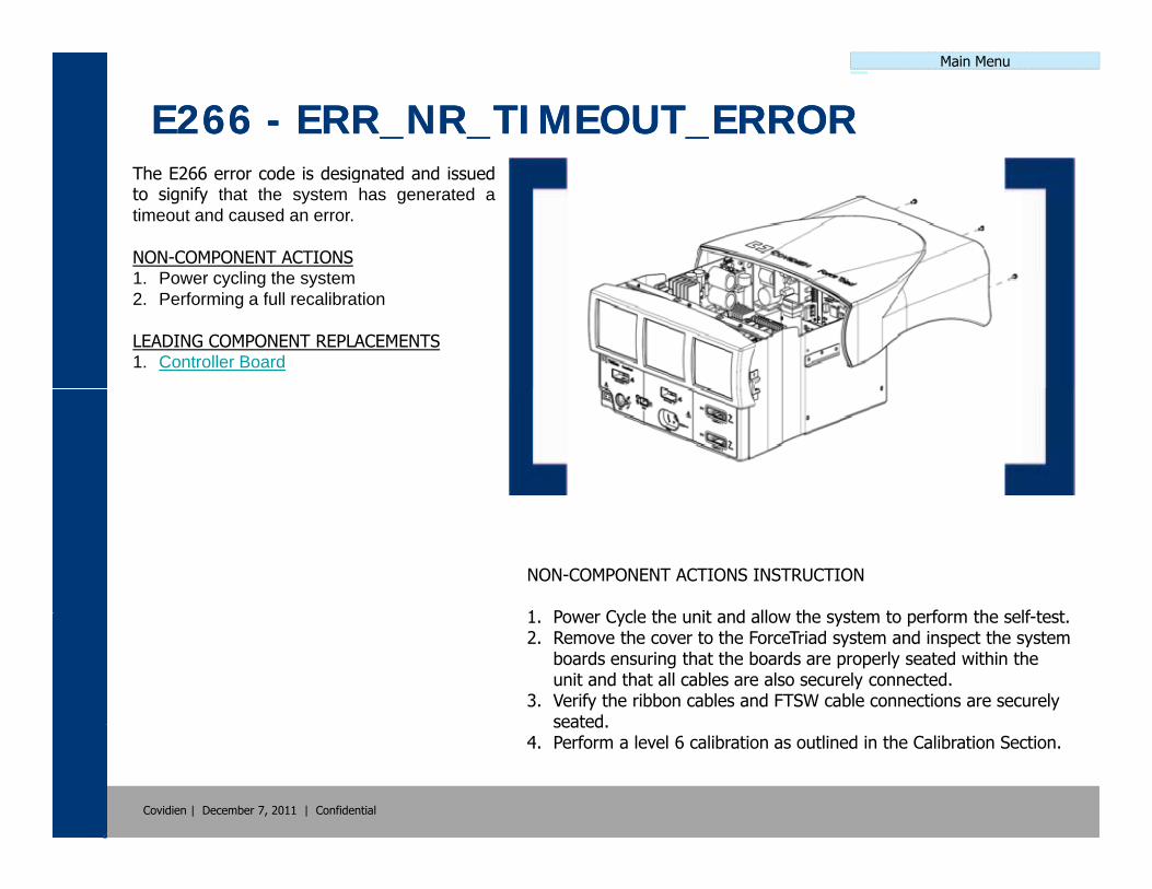
E266 E266 -- ERR_NR_TIMEOUT_ERRORERR_NR_TIMEOUT_ERRORThe E266 error code is designated and issuedto signify that the system has generated atimeout and caused an error.
NON-COMPONENT ACTIONS1 Power cycling the system1. Power cycling the system2. Performing a full recalibration
LEADING COMPONENT REPLACEMENTS1. Controller Board
NON-COMPONENT ACTIONS INSTRUCTION
1 P C l th it d ll th t t f th lf t t1. Power Cycle the unit and allow the system to perform the self-test.2. Remove the cover to the ForceTriad system and inspect the system
boards ensuring that the boards are properly seated within the unit and that all cables are also securely connected.
3. Verify the ribbon cables and FTSW cable connections are securely seated
Covidien | December 7, 2011 | Confidential
seated.4. Perform a level 6 calibration as outlined in the Calibration Section.

Main Menu
E267 E267 -- ERR_NR_GEN_ERRORERR_NR_GEN_ERRORThe E267 error code is designated and issuedto signify that the system has generated anunknown system error.
NON-COMPONENT ACTIONS1 Power cycling the system1. Power cycling the system2. Performing a full recalibration
LEADING COMPONENT REPLACEMENTS1. Controller Board
NON-COMPONENT ACTIONS INSTRUCTION
1 P C l th it d ll th t t f th lf t t1. Power Cycle the unit and allow the system to perform the self-test.2. Remove the cover to the ForceTriad system and inspect the system
boards ensuring that the boards are properly seated within the unit and that all cables are also securely connected.
3. Perform a level 6 calibration as outlined in the Calibration Section.
Covidien | December 7, 2011 | Confidential

Main Menu
E268 E268 -- ERR_NR_SELF_TEST_ERRORERR_NR_SELF_TEST_ERRORThe E268 error code is designated and issuedto signify that the system has failed the initialstart-up self test and generated an error.
NON-COMPONENT ACTIONS1 Power cycling the system1. Power cycling the system2. Performing a full recalibration
LEADING COMPONENT REPLACEMENTS1. Controller Board
NON-COMPONENT ACTIONS INSTRUCTION
1 P C l th it d ll th t t f th lf t t1. Power Cycle the unit and allow the system to perform the self-test.2. Remove the cover to the ForceTriad system and inspect the system
boards ensuring that the boards are properly seated within the unit and that all cables are also securely connected.
3. Perform a level 6 calibration as outlined in the Calibration Section.
Covidien | December 7, 2011 | Confidential

Main Menu
E269 E269 -- ERR_NR_DISPLAY_ERRORERR_NR_DISPLAY_ERRORThe E269 error code is designated and issuedto signify that the system has generated anerror due to a display issue during start-up.
NON-COMPONENT ACTIONS1 Power cycling the system1. Power cycling the system2. Performing a full recalibration
LEADING COMPONENT REPLACEMENTS1. Displays Cables2. Displayssp ays3. Controller Board
NON-COMPONENT ACTIONS INSTRUCTION
1 P C l th it d ll th t t f th lf t t1. Power Cycle the unit and allow the system to perform the self-test.2. Remove the cover to the ForceTriad system and inspect the system
boards ensuring that the boards are properly seated within the unit and that all cables are also securely connected.
3. Perform a level 6 calibration as outlined in the Calibration Section.
Covidien | December 7, 2011 | Confidential

Main Menu
E270 E270 -- ERR_NR_AUDIBLE_ERRORERR_NR_AUDIBLE_ERRORThe E270 error code is designated and issuedto signify that the system has failed theaudible self test and generated an error.
NON-COMPONENT ACTIONS1 Power cycling the system1. Power cycling the system2. Performing a full recalibration
LEADING COMPONENT REPLACEMENTS1. Foot Switch Board2. Controller Board2. Controller Board
NON-COMPONENT ACTIONS INSTRUCTION
1 P C l th it d ll th t t f th lf t t1. Power Cycle the unit and allow the system to perform the self-test.2. Remove the cover to the ForceTriad system and inspect the system
boards ensuring that the boards are properly seated within the unit and that all cables are also securely connected.
3. Perform a level 6 calibration as outlined in the Calibration Section.
Covidien | December 7, 2011 | Confidential

Main Menu
E271 E271 -- ERR_NR_STUCK_BUTTON_ERRORERR_NR_STUCK_BUTTON_ERRORThe E271 error code is designated and issuedto signify that the system has generated anerror during the self-test due to a stuck button.
NON-COMPONENT ACTIONS1 Power cycling the system1. Power cycling the system2. Performing a full recalibration
LEADING COMPONENT REPLACEMENTS1. Controller Board2. Displays2. Displays3. FTSW Board
NON-COMPONENT ACTIONS INSTRUCTION
1 P C l th it d ll th t t f th lf t t1. Power Cycle the unit and allow the system to perform the self-test.2. Remove the cover to the ForceTriad system and inspect the system
boards ensuring that the boards are properly seated within the unit and that all cables are also securely connected.
3. Perform a level 6 calibration as outlined in the Calibration Section.
Covidien | December 7, 2011 | Confidential
Main Menu
E272 E272 –– NOT_USEDNOT_USEDThe E272 error code is not used.
Should you have a version of ForceTriad thatdelivers a E272 error code, please contactyour local Covidien Customer Servicerepresentative for further informationrepresentative for further information.
Covidien | December 7, 2011 | Confidential

Main Menu
E273 E273 -- ERR_NR_INTER_PROC_COM_ERRORERR_NR_INTER_PROC_COM_ERRORThe E273 error code is designated and issuedto signify that the system has generated anerror during self-test due to an inter-processorcommunication issue.
NON COMPONENT ACTIONSNON-COMPONENT ACTIONS1. Power cycling the system2. Performing a full recalibration
LEADING COMPONENT REPLACEMENTS1. Controller BoardCo t o e oa d
NON-COMPONENT ACTIONS INSTRUCTION
1 P C l th it d ll th t t f th lf t t1. Power Cycle the unit and allow the system to perform the self-test.2. Remove the cover to the ForceTriad system and inspect the system
boards ensuring that the boards are properly seated within the unit and that all cables are also securely connected.
3. Perform a level 6 calibration as outlined in the Calibration Section.
Covidien | December 7, 2011 | Confidential

Main Menu
E274 E274 -- ERR_NR_CRITICAL_DATA_ERRORERR_NR_CRITICAL_DATA_ERRORThe E274 error code is designated and issuedto signify that the system has generated anerror during self-test where the unit did notreceive critical information required for start-up. This is most commonly seen whencalibration is required on the unitcalibration is required on the unit.
NON-COMPONENT ACTIONS1. Power cycling the system2. Performing a full recalibration
LEADING COMPONENT REPLACEMENTS1. Scanners2. Controller Board3. Scanner Cables
NON-COMPONENT ACTIONS INSTRUCTION
1 P C l th it d ll th t t f th lf t t1. Power Cycle the unit and allow the system to perform the self-test.2. Remove the cover to the ForceTriad system and inspect the system
boards ensuring that the boards are properly seated within the unit and that all cables are also securely connected.
3. Perform a level 6 calibration as outlined in the Calibration Section.
Covidien | December 7, 2011 | Confidential

Main Menu
E275 E275 -- ERR_NR_MULTI_TASKING_ERRORERR_NR_MULTI_TASKING_ERRORThe E275 error code is designated and issuedto signify that the system has generated anerror during self-test while multi-tasking.
NON-COMPONENT ACTIONS1 Power cycling the system1. Power cycling the system2. Performing a full recalibration
LEADING COMPONENT REPLACEMENTS1. Controller Board
NON-COMPONENT ACTIONS INSTRUCTION
1 P C l th it d ll th t t f th lf t t1. Power Cycle the unit and allow the system to perform the self-test.2. Remove the cover to the ForceTriad system and inspect the system
boards ensuring that the boards are properly seated within the unit and that all cables are also securely connected.
3. Verify the ribbon cables and FTSW cable connections are securely seated
Covidien | December 7, 2011 | Confidential
seated.4. Perform a level 6 calibration as outlined in the Calibration Section.

Main Menu
E276 E276 -- ERR_NR_ANALOG_SENSOR_ERRORERR_NR_ANALOG_SENSOR_ERRORThe E276 error code is designated and issuedto signify that the system has generated anerror during self-test while testing an analogsensor.
NON COMPONENT ACTIONSNON-COMPONENT ACTIONS1. Power cycling the system2. Performing a full recalibration
LEADING COMPONENT REPLACEMENTS1. RF Board1. RF Board
NON-COMPONENT ACTIONS INSTRUCTION
1 P C l th it d ll th t t f th lf t t1. Power Cycle the unit and allow the system to perform the self-test.2. Remove the cover to the ForceTriad system and inspect the system
boards ensuring that the boards are properly seated within the unit and that all cables are also securely connected.
3. Perform a level 6 calibration as outlined in the Calibration Section.
Covidien | December 7, 2011 | Confidential

Main Menu
E277 E277 -- ERR_NR_RF_SHUT_DWN_1_ERRORERR_NR_RF_SHUT_DWN_1_ERRORThe E277 error code is designated and issuedto signify that the system has generated anerror during RF self-test #1 while attempting toshutdown the RF generation.
NON COMPONENT ACTIONSNON-COMPONENT ACTIONS1. Power cycling the system2. Performing a full recalibration
LEADING COMPONENT REPLACEMENTS1. HVDC BoardC oa d2. Controller Board
NON-COMPONENT ACTIONS INSTRUCTION
1 P C l th it d ll th t t f th lf t t1. Power Cycle the unit and allow the system to perform the self-test.2. Remove the cover to the ForceTriad system and inspect the system
boards ensuring that the boards are properly seated within the unit and that all cables are also securely connected.
3. Perform a level 6 calibration as outlined in the Calibration Section.
Covidien | December 7, 2011 | Confidential

Main Menu
E278 E278 -- ERR_NR_RF_SHUT_DWN_2_ERRORERR_NR_RF_SHUT_DWN_2_ERRORThe E289 error code is designated and issuedto signify that the system has generated anerror during RF self-test #2 while attempting toshutdown the RF generation.
NON COMPONENT ACTIONSNON-COMPONENT ACTIONS1. Power cycling the system2. Performing a full recalibration
LEADING COMPONENT REPLACEMENTS1. RF Boardoa d
NON-COMPONENT ACTIONS INSTRUCTION
1 P C l th it d ll th t t f th lf t t1. Power Cycle the unit and allow the system to perform the self-test.2. Remove the cover to the ForceTriad system and inspect the system
boards ensuring that the boards are properly seated within the unit and that all cables are also securely connected.
3. Perform a level 6 calibration as outlined in the Calibration Section.
Covidien | December 7, 2011 | Confidential

Main Menu
E279 E279 -- ERR_NR_RF_SHUT_DWN_3_ERRORERR_NR_RF_SHUT_DWN_3_ERRORThe E279 error code is designated and issuedto signify that the system has generated anerror during RF self-test #3 while attempting toshutdown the RF generation.
NON COMPONENT ACTIONSNON-COMPONENT ACTIONS1. Power cycling the system2. Performing a full recalibration
LEADING COMPONENT REPLACEMENTS1. RF Boardoa d
NON-COMPONENT ACTIONS INSTRUCTION
1 P C l th it d ll th t t f th lf t t1. Power Cycle the unit and allow the system to perform the self-test.2. Remove the cover to the ForceTriad system and inspect the system
boards ensuring that the boards are properly seated within the unit and that all cables are also securely connected.
3. Perform a level 6 calibration as outlined in the Calibration Section.
Covidien | December 7, 2011 | Confidential
Main Menu
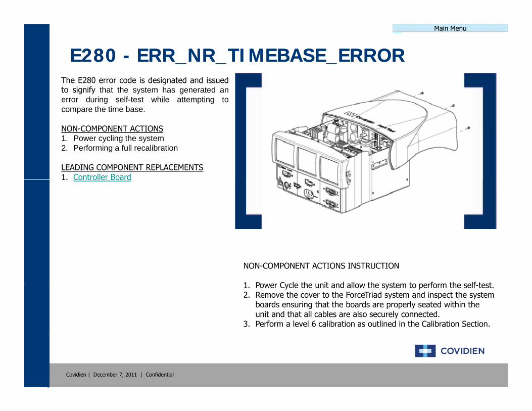
E280 E280 -- ERR_NR_TIMEBASE_ERRORERR_NR_TIMEBASE_ERRORThe E280 error code is designated and issuedto signify that the system has generated anerror during self-test while attempting tocompare the time base.
NON COMPONENT ACTIONSNON-COMPONENT ACTIONS1. Power cycling the system2. Performing a full recalibration
LEADING COMPONENT REPLACEMENTS1. Controller Board1. Controller Board
NON-COMPONENT ACTIONS INSTRUCTION
1 P C l th it d ll th t t f th lf t t1. Power Cycle the unit and allow the system to perform the self-test.2. Remove the cover to the ForceTriad system and inspect the system
boards ensuring that the boards are properly seated within the unit and that all cables are also securely connected.
3. Perform a level 6 calibration as outlined in the Calibration Section.
Covidien | December 7, 2011 | Confidential

Main Menu
E281 E281 -- ERR_NR_SYS_WATCH_DOG_ERRORERR_NR_SYS_WATCH_DOG_ERRORThe E281 error code is designated and issuedto signify that the system has generated acommunication error during self-test.
NON-COMPONENT ACTIONS1 Power cycling the system1. Power cycling the system2. Performing a full recalibration
LEADING COMPONENT REPLACEMENTS1. Controller Board
NON-COMPONENT ACTIONS INSTRUCTION
1 P C l th it d ll th t t f th lf t t1. Power Cycle the unit and allow the system to perform the self-test.2. Remove the cover to the ForceTriad system and inspect the system
boards ensuring that the boards are properly seated within the unit and that all cables are also securely connected.
3. Perform a level 6 calibration as outlined in the Calibration Section.
Covidien | December 7, 2011 | Confidential

Main Menu
E282 E282 -- ERR_NR_ICL_PROG_ERRORERR_NR_ICL_PROG_ERRORThe E282 error code is designated and issuedto signify that the system has generated anerror during self-test while attempting to pullinformation from the ICL chip on the controllerboard.
NON-COMPONENT ACTIONS1. Power cycling the system2. Performing a full recalibration
LEADING COMPONENT REPLACEMENTSLEADING COMPONENT REPLACEMENTS1. Controller Board
NON-COMPONENT ACTIONS INSTRUCTION
1 P C l th it d ll th t t f th lf t t1. Power Cycle the unit and allow the system to perform the self-test.2. Remove the cover to the ForceTriad system and inspect the system
boards ensuring that the boards are properly seated within the unit and that all cables are also securely connected.
3. Perform a level 6 calibration as outlined in the Calibration Section.
Covidien | December 7, 2011 | Confidential

Main Menu
E283 E283 -- ERR_NR_RAM_MEMORY_ERRORERR_NR_RAM_MEMORY_ERRORThe E283 error code is designated and issuedto signify that the system has generated aRAM error during self-test.
NON-COMPONENT ACTIONS1 Power cycling the system1. Power cycling the system2. Performing a full recalibration
LEADING COMPONENT REPLACEMENTS1. Controller Board
NON-COMPONENT ACTIONS INSTRUCTION
1 P C l th it d ll th t t f th lf t t1. Power Cycle the unit and allow the system to perform the self-test.2. Remove the cover to the ForceTriad system and inspect the system
boards ensuring that the boards are properly seated within the unit and that all cables are also securely connected.
3. Perform a level 6 calibration as outlined in the Calibration Section.
Covidien | December 7, 2011 | Confidential

Main Menu
E284 E284 -- ERR_NR_FLASH_MEMORY_ERRORERR_NR_FLASH_MEMORY_ERRORThe E284 error code is designated and issuedto signify that the system has generated aflash error during self-test.
NON-COMPONENT ACTIONS1 Power cycling the system1. Power cycling the system2. Performing a full recalibration
LEADING COMPONENT REPLACEMENTS1. Controller Board
NON-COMPONENT ACTIONS INSTRUCTION
1 P C l th it d ll th t t f th lf t t1. Power Cycle the unit and allow the system to perform the self-test.2. Remove the cover to the ForceTriad system and inspect the system
boards ensuring that the boards are properly seated within the unit and that all cables are also securely connected.
3. Perform a level 6 calibration as outlined in the Calibration Section.
Covidien | December 7, 2011 | Confidential

Main Menu
E285 E285 -- ERR_NR_INVALID_CONFIG_DATAERR_NR_INVALID_CONFIG_DATAThe E285 error code is designated and issuedto signify that the system has generated anerror during self-test. This particular error is toinform the user the equipment configuration isnot valid or there is checksum error within thesoftwaresoftware.
NON-COMPONENT ACTIONS1. Power cycling the system2. Performing a full recalibration
LEADING COMPONENT REPLACEMENTS1. Controller Board
NON-COMPONENT ACTIONS INSTRUCTION
1 P C l th it d ll th t t f th lf t t1. Power Cycle the unit and allow the system to perform the self-test.2. Remove the cover to the ForceTriad system and inspect the system
boards ensuring that the boards are properly seated within the unit and that all cables are also securely connected.
3. Perform a level 6 calibration as outlined in the Calibration Section.
Covidien | December 7, 2011 | Confidential

Main Menu
E286 E286 -- ERR_NR_NULL_PTRERR_NR_NULL_PTRThe E286 error code is designated and issuedto signify that the system has generated asoftware error where the null pointer wasdetected during self-test.
NON COMPONENT ACTIONSNON-COMPONENT ACTIONS1. Power cycling the system2. Performing a full recalibration
LEADING COMPONENT REPLACEMENTS1. Controller Board1. Controller Board2. Displays
NON-COMPONENT ACTIONS INSTRUCTION
1 P C l th it d ll th t t f th lf t t1. Power Cycle the unit and allow the system to perform the self-test.2. Remove the cover to the ForceTriad system and inspect the system
boards ensuring that the boards are properly seated within the unit and that all cables are also securely connected.
3. Perform a level 6 calibration as outlined in the Calibration Section.
Covidien | December 7, 2011 | Confidential
Main Menu
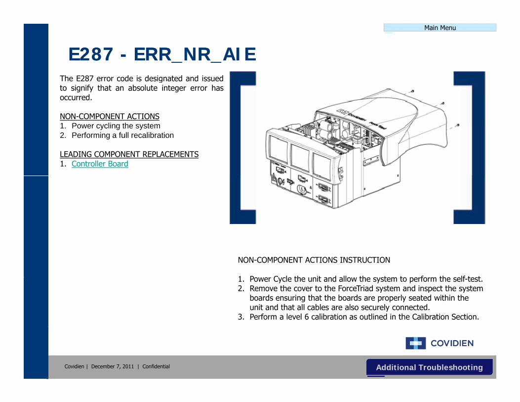
E287 E287 -- ERR_NR_AIEERR_NR_AIEThe E287 error code is designated and issuedto signify that an absolute integer error hasoccurred.
NON-COMPONENT ACTIONS1 Power cycling the system1. Power cycling the system2. Performing a full recalibration
LEADING COMPONENT REPLACEMENTS1. Controller Board
NON-COMPONENT ACTIONS INSTRUCTION
1 P C l th it d ll th t t f th lf t t1. Power Cycle the unit and allow the system to perform the self-test.2. Remove the cover to the ForceTriad system and inspect the system
boards ensuring that the boards are properly seated within the unit and that all cables are also securely connected.
3. Perform a level 6 calibration as outlined in the Calibration Section.
Covidien | December 7, 2011 | Confidential Additional TroubleshootingAdditional Troubleshooting

Main Menu
E288 E288 -- ERR_NR_SENSOR_CLIPERR_NR_SENSOR_CLIPThe E288 error code is designated and issuedto signify that the system has developed aDSP sensor clip error.
NON-COMPONENT ACTIONS1 Power cycling the system1. Power cycling the system2. Performing a full recalibration
LEADING COMPONENT REPLACEMENTS1. HVDC Board2. RF Board2. RF Board3. Controller Board
NON-COMPONENT ACTIONS INSTRUCTION
1 P C l th it d ll th t t f th lf t t1. Power Cycle the unit and allow the system to perform the self-test.2. Remove the cover to the ForceTriad system and inspect the system
boards ensuring that the boards are properly seated within the unit and that all cables are also securely connected.
3. Perform a level 6 calibration as outlined in the Calibration Section.
Covidien | December 7, 2011 | Confidential
Main Menu
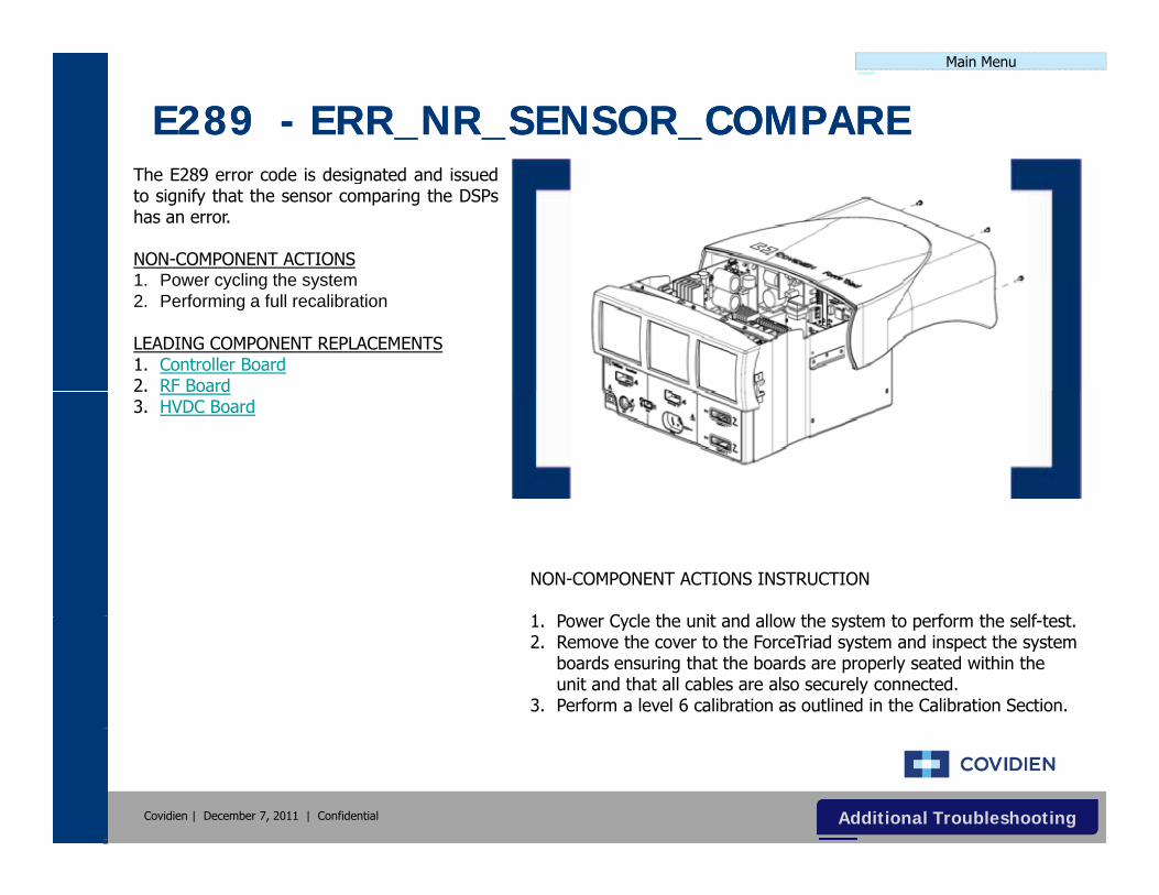
E289 E289 -- ERR_NR_SENSOR_COMPAREERR_NR_SENSOR_COMPAREThe E289 error code is designated and issuedto signify that the sensor comparing the DSPshas an error.
NON-COMPONENT ACTIONS1 Power cycling the system1. Power cycling the system2. Performing a full recalibration
LEADING COMPONENT REPLACEMENTS1. Controller Board2. RF Board2. RF Board3. HVDC Board
NON-COMPONENT ACTIONS INSTRUCTION
1 P C l th it d ll th t t f th lf t t1. Power Cycle the unit and allow the system to perform the self-test.2. Remove the cover to the ForceTriad system and inspect the system
boards ensuring that the boards are properly seated within the unit and that all cables are also securely connected.
3. Perform a level 6 calibration as outlined in the Calibration Section.
Covidien | December 7, 2011 | Confidential Additional TroubleshootingAdditional Troubleshooting

Main Menu
E290 E290 -- ERR_NR_DATA_SAMPLE_ERRORRERR_NR_DATA_SAMPLE_ERRORRThe E290 error code is designated and issuedto signify that the system has generated asampling error while conducting data samplingof the VI.
NON COMPONENT ACTIONSNON-COMPONENT ACTIONS1. Power cycling the system2. Performing a full recalibration
LEADING COMPONENT REPLACEMENTS1. Controller Board1. Controller Board
NON-COMPONENT ACTIONS INSTRUCTION
1 P C l th it d ll th t t f th lf t t1. Power Cycle the unit and allow the system to perform the self-test.2. Remove the cover to the ForceTriad system and inspect the system
boards ensuring that the boards are properly seated within the unit and that all cables are also securely connected.
3. Perform a level 6 calibration as outlined in the Calibration Section.
Covidien | December 7, 2011 | Confidential

Main Menu
E291 E291 -- ERR_NR_COMM_WD_ERRORERR_NR_COMM_WD_ERRORThe E289 error code is designated and issuedto signify that the system has generated awatchdog (communication) error.
NON-COMPONENT ACTIONS1 Power cycling the system1. Power cycling the system2. Performing a full recalibration
LEADING COMPONENT REPLACEMENTS1. Controller Board
NON-COMPONENT ACTIONS INSTRUCTION
1 P C l th it d ll th t t f th lf t t1. Power Cycle the unit and allow the system to perform the self-test.2. Remove the cover to the ForceTriad system and inspect the system
boards ensuring that the boards are properly seated within the unit and that all cables are also securely connected.
3. Perform a level 6 calibration as outlined in the Calibration Section.
Covidien | December 7, 2011 | Confidential

Main Menu
E292 E292 -- ERR_NR_DSP_SW_ERRORERR_NR_DSP_SW_ERRORThe E292 error code is designated and issuedto signify that the system has generated asoftware error caused by issues with the DSP.
NON-COMPONENT ACTIONS1 Power cycling the system1. Power cycling the system2. Performing a full recalibration
LEADING COMPONENT REPLACEMENTS1. Controller Board2. HVDC Board2. HVDC Board
NON-COMPONENT ACTIONS INSTRUCTION
1 P C l th it d ll th t t f th lf t t1. Power Cycle the unit and allow the system to perform the self-test.2. Remove the cover to the ForceTriad system and inspect the system
boards ensuring that the boards are properly seated within the unit and that all cables are also securely connected.
3. Perform a level 6 calibration as outlined in the Calibration Section.
Covidien | December 7, 2011 | Confidential

Main Menu
E293 E293 -- ERR_NR_FLASH_ERRORERR_NR_FLASH_ERRORThe E293 error code is designated and issuedto signify that the system has generated asoftware error while attempting to write to theFLASH memory.
NON COMPONENT ACTIONSNON-COMPONENT ACTIONS1. Power cycling the system2. Performing a full recalibration
LEADING COMPONENT REPLACEMENTS1. Controller Board1. Controller Board
NON-COMPONENT ACTIONS INSTRUCTION
1 P C l th it d ll th t t f th lf t t1. Power Cycle the unit and allow the system to perform the self-test.2. Remove the cover to the ForceTriad system and inspect the system
boards ensuring that the boards are properly seated within the unit and that all cables are also securely connected.
3. Perform a level 6 calibration as outlined in the Calibration Section.
Covidien | December 7, 2011 | Confidential

Main Menu
E294 E294 -- ERR_NR_OS_ERRORERR_NR_OS_ERRORThe E294 error code is designated and issuedto signify that the system has generated anoperating system error in real time.
NON-COMPONENT ACTIONS1 Power cycling the system1. Power cycling the system2. Performing a full recalibration
LEADING COMPONENT REPLACEMENTS1. Controller Board
NON-COMPONENT ACTIONS INSTRUCTION
1 P C l th it d ll th t t f th lf t t1. Power Cycle the unit and allow the system to perform the self-test.2. Remove the cover to the ForceTriad system and inspect the system
boards ensuring that the boards are properly seated within the unit and that all cables are also securely connected.
3. Perform a level 6 calibration as outlined in the Calibration Section.
Covidien | December 7, 2011 | Confidential

Main Menu
E295 E295 -- ERR_NR_NV_STORE_ERRORERR_NR_NV_STORE_ERRORThe E295 error code is designated and issuedto signify that the system has generated asoftware error while attempting to write to theNV store.
NON COMPONENT ACTIONSNON-COMPONENT ACTIONS1. Power cycling the system2. Performing a full recalibration
LEADING COMPONENT REPLACEMENTS1. Controller Board1. Controller Board
NON-COMPONENT ACTIONS INSTRUCTION
1 P C l th it d ll th t t f th lf t t1. Power Cycle the unit and allow the system to perform the self-test.2. Remove the cover to the ForceTriad system and inspect the system
boards ensuring that the boards are properly seated within the unit and that all cables are also securely connected.
3. Perform a level 6 calibration as outlined in the Calibration Section.
Covidien | December 7, 2011 | Confidential

Main Menu
E296 E296 -- ERR_NR_ICL_HB_ERRORERR_NR_ICL_HB_ERRORThe E289 error code is designated and issuedto signify that the system has generated anICL error while monitoring the ICL heartbeat.
NON-COMPONENT ACTIONS1 Power cycling the system1. Power cycling the system2. Performing a full recalibration
LEADING COMPONENT REPLACEMENTS1. Controller Board
NON-COMPONENT ACTIONS INSTRUCTION
1 P C l th it d ll th t t f th lf t t1. Power Cycle the unit and allow the system to perform the self-test.2. Remove the cover to the ForceTriad system and inspect the system
boards ensuring that the boards are properly seated within the unit and that all cables are also securely connected.
3. Perform a level 6 calibration as outlined in the Calibration Section.
Covidien | December 7, 2011 | Confidential

Main Menu
E297 E297 -- ERR_NR_MSG_VIEWER_CTOR_FAILERR_NR_MSG_VIEWER_CTOR_FAILThe E297 error code is designated and issuedto signify that the system has generated asoftware error caused by the failedconstruction of the message viewer.
NON COMPONENT ACTIONSNON-COMPONENT ACTIONS1. Power cycling the system2. Performing a full recalibration
LEADING COMPONENT REPLACEMENTS1. Controller Board1. Controller Board
NON-COMPONENT ACTIONS INSTRUCTION
1 P C l th it d ll th t t f th lf t t1. Power Cycle the unit and allow the system to perform the self-test.2. Remove the cover to the ForceTriad system and inspect the system
boards ensuring that the boards are properly seated within the unit and that all cables are also securely connected.
3. Perform a level 6 calibration as outlined in the Calibration Section.
Covidien | December 7, 2011 | Confidential

Main Menu
E298 E298 -- ERR_NR_SYS_CTRL_REQ_FAILERR_NR_SYS_CTRL_REQ_FAILThe E298 error code is designated and issuedto signify that the system has generated asoftware error due to the system denying therequest to bring up the main menus on thecontroller.
NON-COMPONENT ACTIONS1. Power cycling the system2. Performing a full recalibration
LEADING COMPONENT REPLACEMENTSLEADING COMPONENT REPLACEMENTS1. Controller Board
NON-COMPONENT ACTIONS INSTRUCTION
1 P C l th it d ll th t t f th lf t t1. Power Cycle the unit and allow the system to perform the self-test.2. Remove the cover to the ForceTriad system and inspect the system
boards ensuring that the boards are properly seated within the unit and that all cables are also securely connected.
3. Perform a level 6 calibration as outlined in the Calibration Section.
Covidien | December 7, 2011 | Confidential

Main Menu
E299 E299 -- ERR_NR_LKG_LIMITERR_NR_LKG_LIMITThe E299 error code is designated and issuedto signify that the system has generated anerror due to leakage on the sensor comparefor DSP 2.
NON COMPONENT ACTIONSNON-COMPONENT ACTIONS1. Power cycling the system2. Performing a full recalibration
LEADING COMPONENT REPLACEMENTS1. Controller Board1. Controller Board2. RF Board
NON-COMPONENT ACTIONS INSTRUCTION
1 P C l th it d ll th t t f th lf t t1. Power Cycle the unit and allow the system to perform the self-test.2. Remove the cover to the ForceTriad system and inspect the system
boards ensuring that the boards are properly seated within the unit and that all cables are also securely connected.
3. Perform a level 6 calibration as outlined in the Calibration Section.
Covidien | December 7, 2011 | Confidential
Main Menu
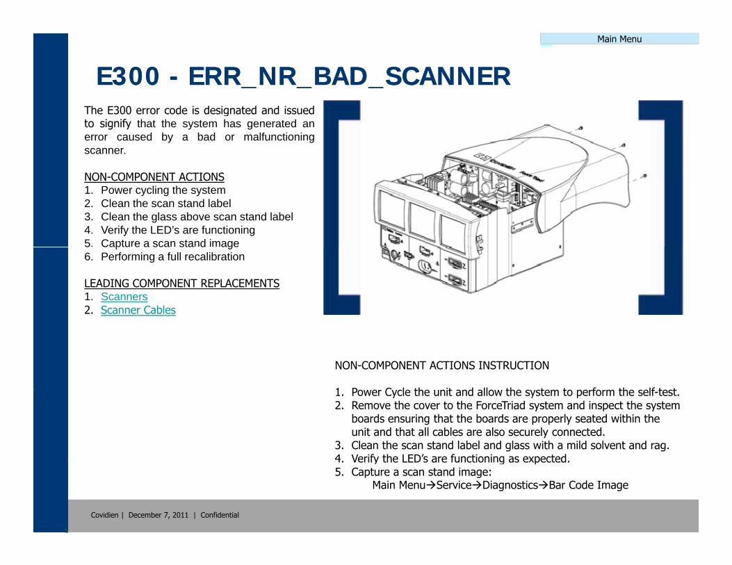
E300 E300 -- ERR_NR_BAD_SCANNERERR_NR_BAD_SCANNERThe E300 error code is designated and issuedto signify that the system has generated anerror caused by a bad or malfunctioningscanner.
NON COMPONENT ACTIONSNON-COMPONENT ACTIONS1. Power cycling the system2. Clean the scan stand label3. Clean the glass above scan stand label4. Verify the LED’s are functioning5. Capture a scan stand image5 Captu e a sca sta d age6. Performing a full recalibration
LEADING COMPONENT REPLACEMENTS1. Scanners2. Scanner Cables
NON-COMPONENT ACTIONS INSTRUCTION
1 P C l th it d ll th t t f th lf t t1. Power Cycle the unit and allow the system to perform the self-test.2. Remove the cover to the ForceTriad system and inspect the system
boards ensuring that the boards are properly seated within the unit and that all cables are also securely connected.
3. Clean the scan stand label and glass with a mild solvent and rag.4 Verify the LED’s are functioning as expected
Covidien | December 7, 2011 | Confidential
4. Verify the LED s are functioning as expected.5. Capture a scan stand image:
Main MenuServiceDiagnosticsBar Code Image
Main Menu
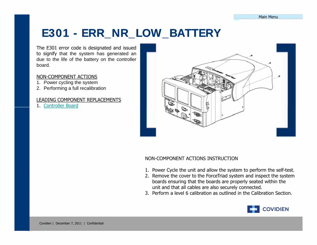
E301 E301 -- ERR_NR_LOW_BATTERYERR_NR_LOW_BATTERYThe E301 error code is designated and issuedto signify that the system has generated andue to the life of the battery on the controllerboard.
NON COMPONENT ACTIONSNON-COMPONENT ACTIONS1. Power cycling the system2. Performing a full recalibration
LEADING COMPONENT REPLACEMENTS1. Controller Board1. Controller Board
NON-COMPONENT ACTIONS INSTRUCTION
1 P C l th it d ll th t t f th lf t t1. Power Cycle the unit and allow the system to perform the self-test.2. Remove the cover to the ForceTriad system and inspect the system
boards ensuring that the boards are properly seated within the unit and that all cables are also securely connected.
3. Perform a level 6 calibration as outlined in the Calibration Section.
Covidien | December 7, 2011 | Confidential
Main Menu
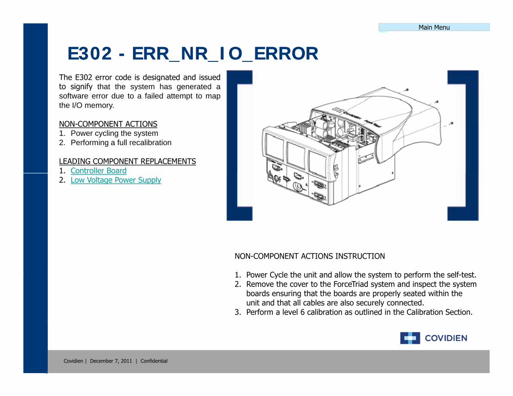
E302 E302 -- ERR_NR_IO_ERRORERR_NR_IO_ERRORThe E302 error code is designated and issuedto signify that the system has generated asoftware error due to a failed attempt to mapthe I/O memory.
NON COMPONENT ACTIONSNON-COMPONENT ACTIONS1. Power cycling the system2. Performing a full recalibration
LEADING COMPONENT REPLACEMENTS1. Controller Board1. Controller Board2. Low Voltage Power Supply
NON-COMPONENT ACTIONS INSTRUCTION
1 P C l th it d ll th t t f th lf t t1. Power Cycle the unit and allow the system to perform the self-test.2. Remove the cover to the ForceTriad system and inspect the system
boards ensuring that the boards are properly seated within the unit and that all cables are also securely connected.
3. Perform a level 6 calibration as outlined in the Calibration Section.
Covidien | December 7, 2011 | Confidential

Main Menu
E303 E303 -- ERR_NR_DSP_VERIFY_ERRORERR_NR_DSP_VERIFY_ERRORThe E303 error code is designated and issuedto signify that the system has generated asoftware error due to a failed verification of theDSP.
NON COMPONENT ACTIONSNON-COMPONENT ACTIONS1. Power cycling the system2. Performing a full recalibration
LEADING COMPONENT REPLACEMENTS1. Controller Board1. Controller Board
NON-COMPONENT ACTIONS INSTRUCTION
1 P C l th it d ll th t t f th lf t t1. Power Cycle the unit and allow the system to perform the self-test.2. Remove the cover to the ForceTriad system and inspect the system
boards ensuring that the boards are properly seated within the unit and that all cables are also securely connected.
3. Perform a level 6 calibration as outlined in the Calibration Section.
Covidien | December 7, 2011 | Confidential
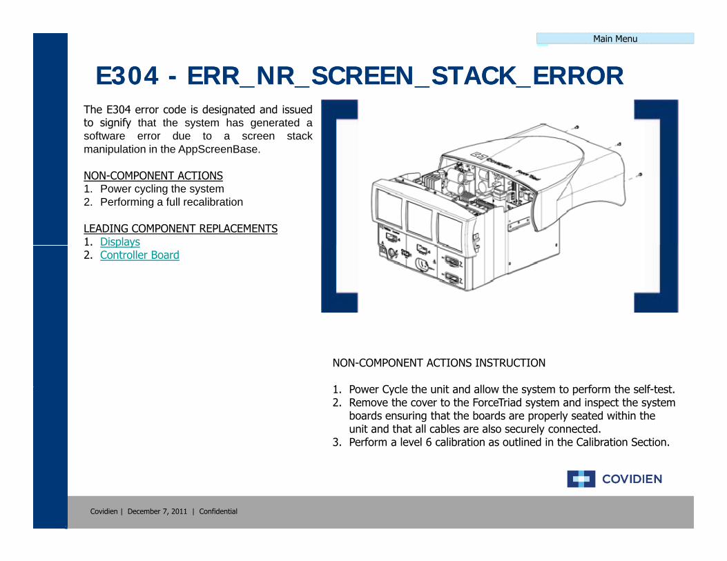
Main Menu
E304 E304 -- ERR_NR_SCREEN_STACK_ERRORERR_NR_SCREEN_STACK_ERRORThe E304 error code is designated and issuedto signify that the system has generated asoftware error due to a screen stackmanipulation in the AppScreenBase.
NON COMPONENT ACTIONSNON-COMPONENT ACTIONS1. Power cycling the system2. Performing a full recalibration
LEADING COMPONENT REPLACEMENTS1. Displays1. Displays2. Controller Board
NON-COMPONENT ACTIONS INSTRUCTION
1 P C l th it d ll th t t f th lf t t1. Power Cycle the unit and allow the system to perform the self-test.2. Remove the cover to the ForceTriad system and inspect the system
boards ensuring that the boards are properly seated within the unit and that all cables are also securely connected.
3. Perform a level 6 calibration as outlined in the Calibration Section.
Covidien | December 7, 2011 | Confidential

Main Menu
E305 E305 -- ERR_NR_ROM_ERRORERR_NR_ROM_ERRORThe E305 error code is designated and issuedto signify that the system has generated asoftware error during the self-test caused by aROM failure.
NON COMPONENT ACTIONSNON-COMPONENT ACTIONS1. Power cycling the system2. Performing a full recalibration
LEADING COMPONENT REPLACEMENTS1. Controller Board1. Controller Board
NON-COMPONENT ACTIONS INSTRUCTION
1 P C l th it d ll th t t f th lf t t1. Power Cycle the unit and allow the system to perform the self-test.2. Remove the cover to the ForceTriad system and inspect the system
boards ensuring that the boards are properly seated within the unit and that all cables are also securely connected.
3. Perform a level 6 calibration as outlined in the Calibration Section.
Covidien | December 7, 2011 | Confidential
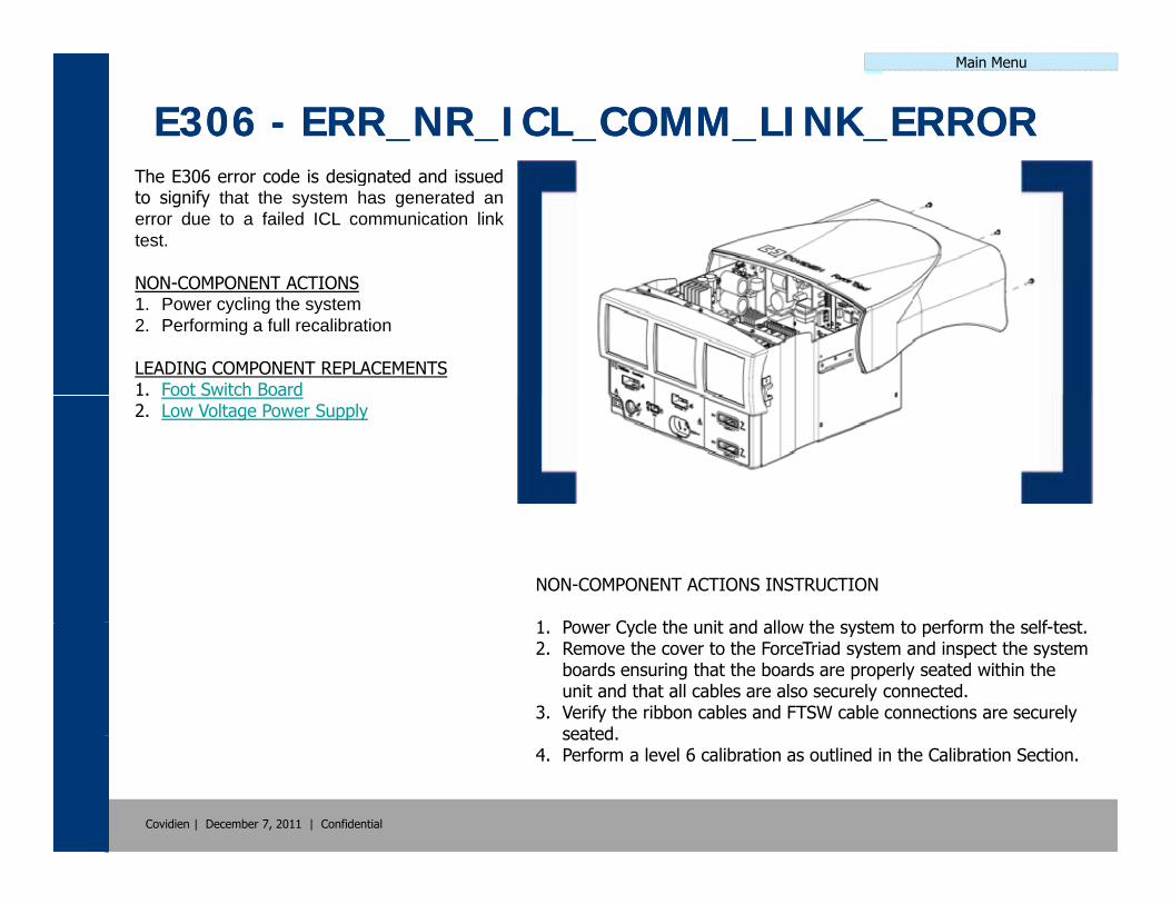
Main Menu
E306 E306 -- ERR_NR_ICL_COMM_LINK_ERRORERR_NR_ICL_COMM_LINK_ERRORThe E306 error code is designated and issuedto signify that the system has generated anerror due to a failed ICL communication linktest.
NON COMPONENT ACTIONSNON-COMPONENT ACTIONS1. Power cycling the system2. Performing a full recalibration
LEADING COMPONENT REPLACEMENTS1. Foot Switch Board1. Foot Switch Board2. Low Voltage Power Supply
NON-COMPONENT ACTIONS INSTRUCTION
1 P C l th it d ll th t t f th lf t t1. Power Cycle the unit and allow the system to perform the self-test.2. Remove the cover to the ForceTriad system and inspect the system
boards ensuring that the boards are properly seated within the unit and that all cables are also securely connected.
3. Verify the ribbon cables and FTSW cable connections are securely seated
Covidien | December 7, 2011 | Confidential
seated.4. Perform a level 6 calibration as outlined in the Calibration Section.
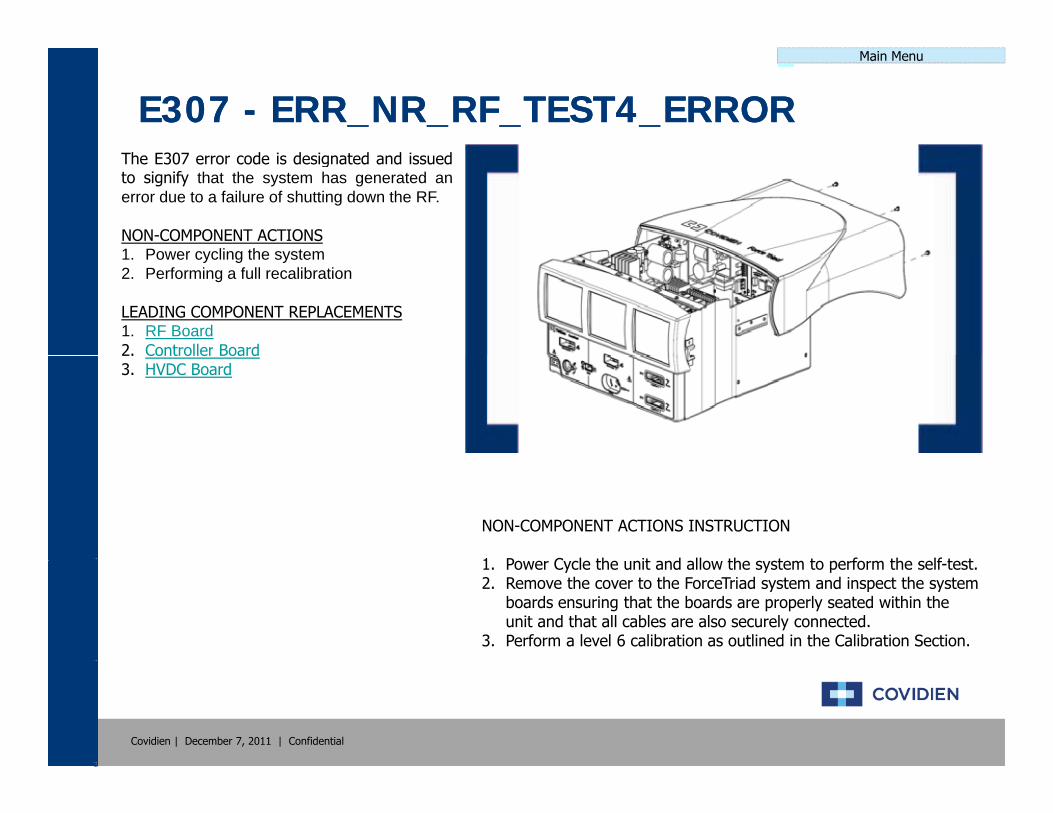
Main Menu
E307 E307 -- ERR_NR_RF_TEST4_ERRORERR_NR_RF_TEST4_ERRORThe E307 error code is designated and issuedto signify that the system has generated anerror due to a failure of shutting down the RF.
NON-COMPONENT ACTIONS1 Power cycling the system1. Power cycling the system2. Performing a full recalibration
LEADING COMPONENT REPLACEMENTS1. RF Board2. Controller Board2. Controller Board3. HVDC Board
NON-COMPONENT ACTIONS INSTRUCTION
1 P C l th it d ll th t t f th lf t t1. Power Cycle the unit and allow the system to perform the self-test.2. Remove the cover to the ForceTriad system and inspect the system
boards ensuring that the boards are properly seated within the unit and that all cables are also securely connected.
3. Perform a level 6 calibration as outlined in the Calibration Section.
Covidien | December 7, 2011 | Confidential
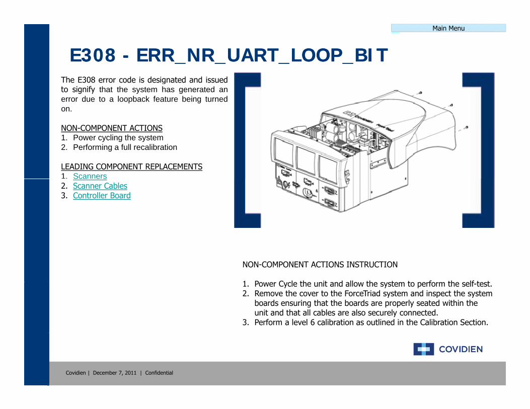
Main Menu
E308 E308 -- ERR_NR_UART_LOOP_BITERR_NR_UART_LOOP_BITThe E308 error code is designated and issuedto signify that the system has generated anerror due to a loopback feature being turnedon.
NON COMPONENT ACTIONSNON-COMPONENT ACTIONS1. Power cycling the system2. Performing a full recalibration
LEADING COMPONENT REPLACEMENTS1. ScannersSca e s2. Scanner Cables3. Controller Board
NON-COMPONENT ACTIONS INSTRUCTION
1 P C l th it d ll th t t f th lf t t1. Power Cycle the unit and allow the system to perform the self-test.2. Remove the cover to the ForceTriad system and inspect the system
boards ensuring that the boards are properly seated within the unit and that all cables are also securely connected.
3. Perform a level 6 calibration as outlined in the Calibration Section.
Covidien | December 7, 2011 | Confidential

Main Menu
E309 E309 -- ERR_NR_RDM_INVALID_WINDOWERR_NR_RDM_INVALID_WINDOWThe E309 error code is designated and issuedto signify that the system has generated anerror due to an invalid window pointer signalgenerated by the remote controller.
NON COMPONENT ACTIONSNON-COMPONENT ACTIONS1. Power cycling the system2. Performing a full recalibration
LEADING COMPONENT REPLACEMENTS1. Displayssp ays2. Displays Cables3. Controller Board
NON-COMPONENT ACTIONS INSTRUCTION
1 P C l th it d ll th t t f th lf t t1. Power Cycle the unit and allow the system to perform the self-test.2. Remove the cover to the ForceTriad system and inspect the system
boards ensuring that the boards are properly seated within the unit and that all cables are also securely connected.
3. Perform a level 6 calibration as outlined in the Calibration Section.
Covidien | December 7, 2011 | Confidential

Main Menu
E310 E310 -- ERR_NR_RDM_INVALID_FIELD_LISTERR_NR_RDM_INVALID_FIELD_LISTThe E310 error code is designated and issuedto signify that the system has generated anerror due to an invalid field list signalgenerated by the remote controller.
NON COMPONENT ACTIONSNON-COMPONENT ACTIONS1. Power cycling the system2. Performing a full recalibration
LEADING COMPONENT REPLACEMENTS1. Displayssp ays2. Displays Cables3. Controller Board
NON-COMPONENT ACTIONS INSTRUCTION
1 P C l th it d ll th t t f th lf t t1. Power Cycle the unit and allow the system to perform the self-test.2. Remove the cover to the ForceTriad system and inspect the system
boards ensuring that the boards are properly seated within the unit and that all cables are also securely connected.
3. Perform a level 6 calibration as outlined in the Calibration Section.
Covidien | December 7, 2011 | Confidential

Main Menu
E311 E311 -- ERR_NR_INVALID_RF_HDW_CONFIGERR_NR_INVALID_RF_HDW_CONFIGThe E311 error code is designated and issuedto signify that the system has generated anerror due to the HOST receiving a combinationof hardware versions that are invalid.
NON COMPONENT ACTIONSNON-COMPONENT ACTIONS1. Power cycling the system2. Performing a full recalibration
LEADING COMPONENT REPLACEMENTS1. Controller Board1. Controller Board
NON-COMPONENT ACTIONS INSTRUCTION
1 P C l th it d ll th t t f th lf t t1. Power Cycle the unit and allow the system to perform the self-test.2. Remove the cover to the ForceTriad system and inspect the system
boards ensuring that the boards are properly seated within the unit and that all cables are also securely connected.
3. Perform a level 6 calibration as outlined in the Calibration Section.
Covidien | December 7, 2011 | Confidential
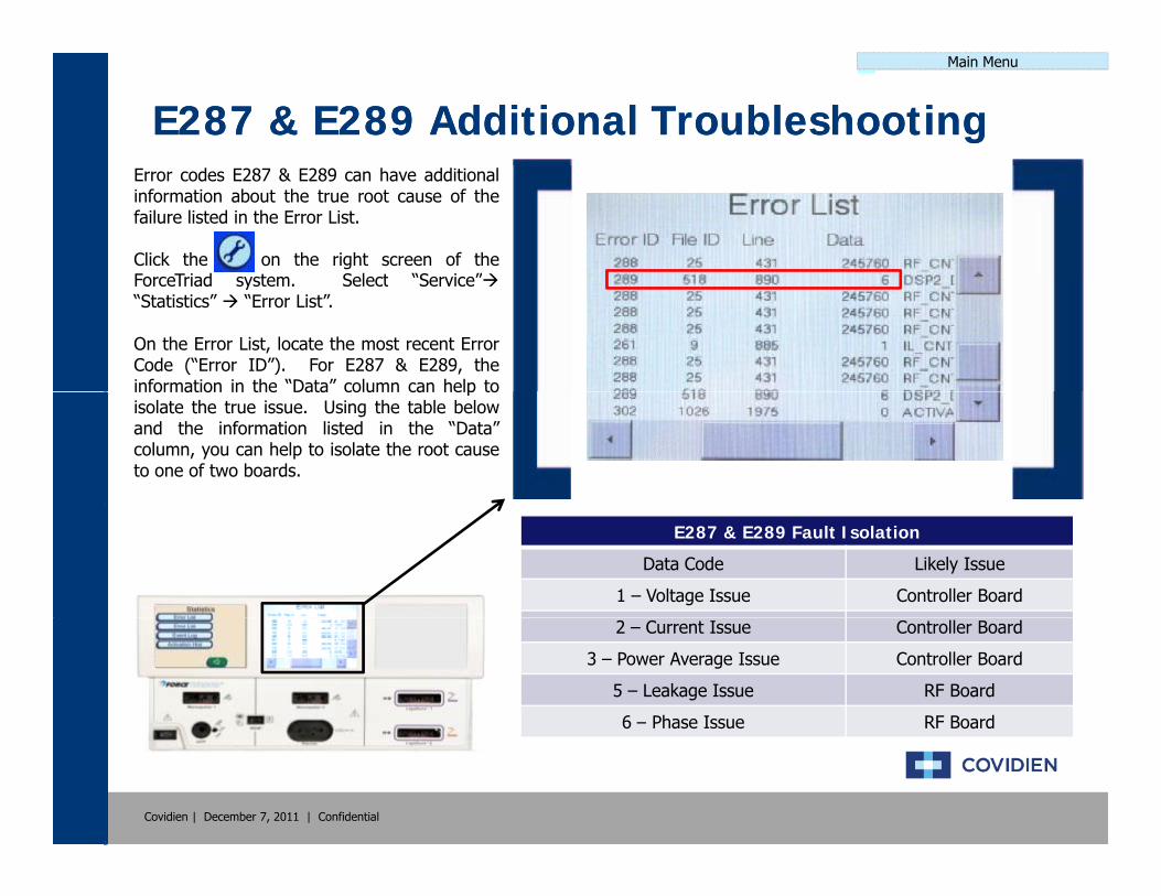
Main Menu
E287 & E289 Additional TroubleshootingE287 & E289 Additional TroubleshootingError codes E287 & E289 can have additionalinformation about the true root cause of thefailure listed in the Error List.
Click the on the right screen of theForceTriad system Select “Service”ForceTriad system. Select Service “Statistics” “Error List”.
On the Error List, locate the most recent ErrorCode (“Error ID”). For E287 & E289, theinformation in the “Data” column can help toinformation in the Data column can help toisolate the true issue. Using the table belowand the information listed in the “Data”column, you can help to isolate the root causeto one of two boards.
E287 & E289 Fault Isolation
Data Code Likely Issue
1 – Voltage Issue Controller Board
2 – Current Issue Controller Board
3 – Power Average Issue Controller Board
5 – Leakage Issue RF Board
6 – Phase Issue RF Board
Covidien | December 7, 2011 | Confidential
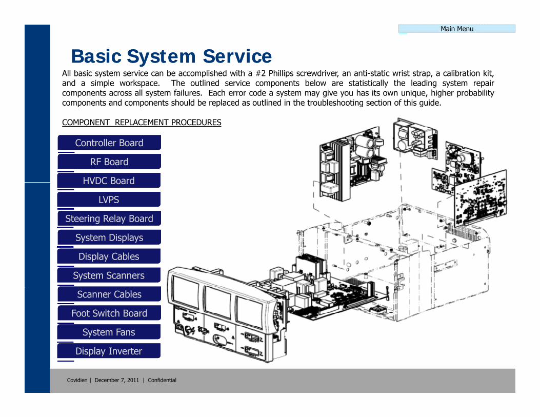
Main Menu
Basic System ServiceBasic System ServiceAll basic system service can be accomplished with a #2 Phillips screwdriver, an anti-static wrist strap, a calibration kit,y p p , p, ,and a simple workspace. The outlined service components below are statistically the leading system repaircomponents across all system failures. Each error code a system may give you has its own unique, higher probabilitycomponents and components should be replaced as outlined in the troubleshooting section of this guide.
COMPONENT REPLACEMENT PROCEDURES
Controller BoardController Board
RF BoardRF Board
HVDC BoardHVDC BoardHVDC BoardHVDC Board
LVPSLVPS
Steering Relay BoardSteering Relay Board
S t Di lS t Di lSystem DisplaysSystem Displays
Display CablesDisplay Cables
System ScannersSystem Scanners
Scanner CablesScanner Cables
Foot Switch BoardFoot Switch Board
System FansSystem Fans
Covidien | December 7, 2011 | Confidential
Display InverterDisplay Inverter
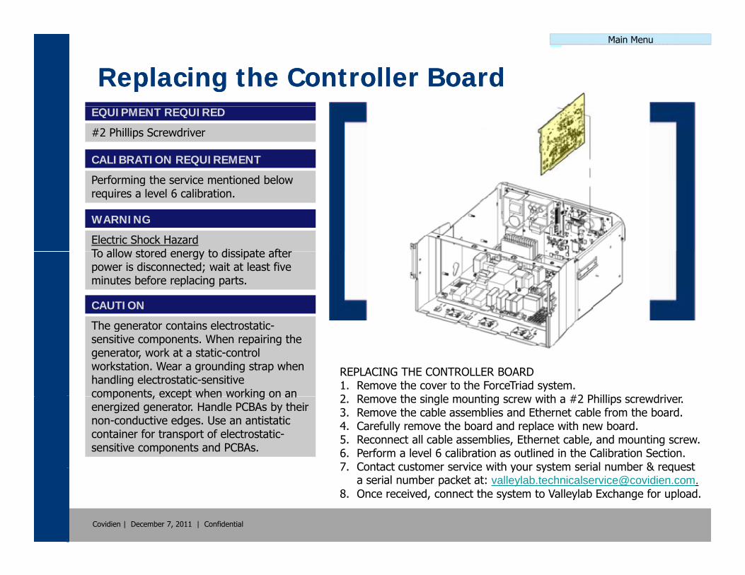
Main Menu
Replacing the Controller BoardReplacing the Controller BoardEQUIPMENT REQUIRED
#2 Phillips Screwdriver
CALIBRATION REQUIREMENT
Performing the service mentioned belowPerforming the service mentioned below requires a level 6 calibration.
WARNING
Electric Shock HazardTo allow stored energy to dissipate afterTo allow stored energy to dissipate after power is disconnected; wait at least five minutes before replacing parts.
CAUTION
The generator contains electrostatic
REPLACING THE CONTROLLER BOARD1. Remove the cover to the ForceTriad system.2 R th i l ti ith #2 Philli d i
The generator contains electrostatic-sensitive components. When repairing the generator, work at a static-control workstation. Wear a grounding strap when handling electrostatic-sensitive components, except when working on an 2. Remove the single mounting screw with a #2 Phillips screwdriver.
3. Remove the cable assemblies and Ethernet cable from the board.4. Carefully remove the board and replace with new board.5. Reconnect all cable assemblies, Ethernet cable, and mounting screw.6. Perform a level 6 calibration as outlined in the Calibration Section.7 Contact customer service with your system serial number & request
components, except when working on an energized generator. Handle PCBAs by their non-conductive edges. Use an antistatic container for transport of electrostatic-sensitive components and PCBAs.
Covidien | December 7, 2011 | Confidential
7. Contact customer service with your system serial number & request a serial number packet at: [email protected].
8. Once received, connect the system to Valleylab Exchange for upload.

Main Menu
Replacing the RF BoardReplacing the RF BoardEQUIPMENT REQUIRED
#2 Phillips Screwdriver
CALIBRATION REQUIREMENT
Performing the service mentioned belowPerforming the service mentioned below requires a level 5 calibration.
WARNING
Electric Shock HazardTo allow stored energy to dissipate afterTo allow stored energy to dissipate after power is disconnected; wait at least five minutes before replacing parts.
CAUTION
The generator contains electrostatic
REPLACING THE RF BOARD1. Remove the cover to the ForceTriad system.2 R th C t ll B d HVDC B d & F t P l
The generator contains electrostatic-sensitive components. When repairing the generator, work at a static-control workstation. Wear a grounding strap when handling electrostatic-sensitive components, except when working on an 2. Remove the Controller Board, HVDC Board, & Front Panel
Assembly in accordance with the Service Manual.3. Remove the cable assemblies from the board.4. Remove nine securing screws holding the board to the chassis.5. Carefully remove the board and replace with new board.6 Reconnect all cable assemblies replace the mounting screws and
components, except when working on an energized generator. Handle PCBAs by their non-conductive edges. Use an antistatic container for transport of electrostatic-sensitive components and PCBAs.
Covidien | December 7, 2011 | Confidential
6. Reconnect all cable assemblies, replace the mounting screws, and reinstall the three previously removed items.
7. Perform a level 5 calibration as outlined in the Calibration Section.
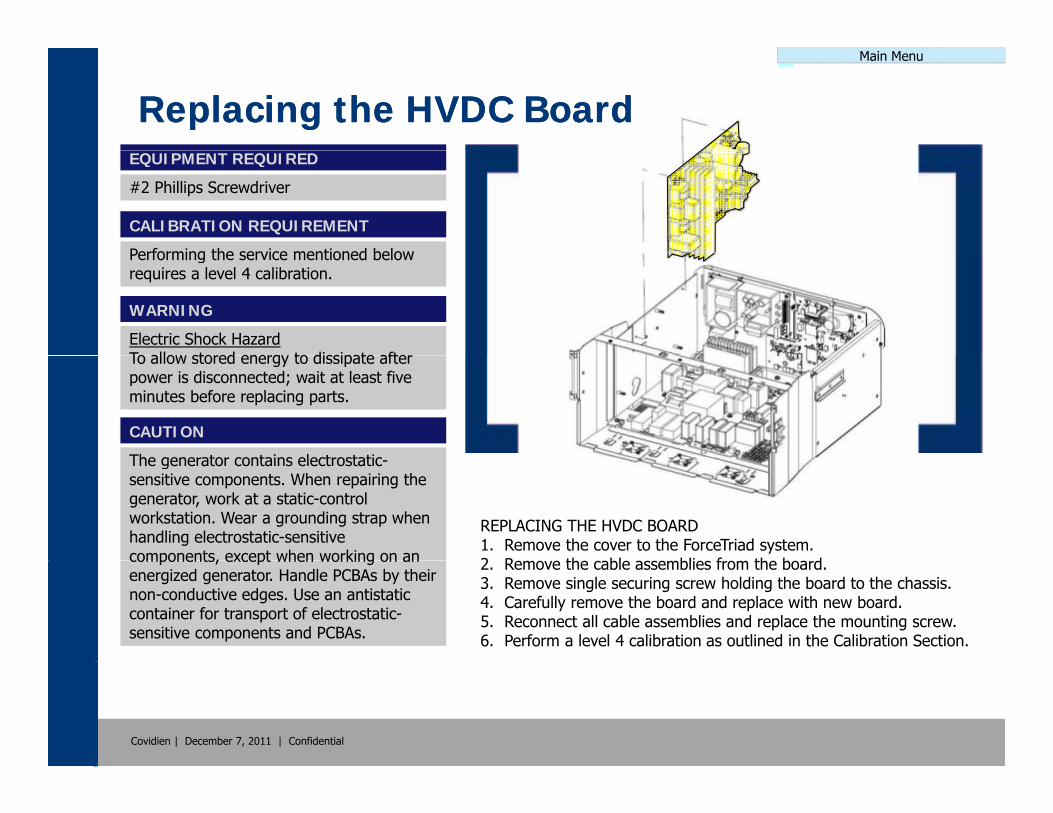
Main Menu
Replacing the HVDC BoardReplacing the HVDC BoardEQUIPMENT REQUIRED
#2 Phillips Screwdriver
CALIBRATION REQUIREMENT
Performing the service mentioned belowPerforming the service mentioned below requires a level 4 calibration.
WARNING
Electric Shock HazardTo allow stored energy to dissipate afterTo allow stored energy to dissipate after power is disconnected; wait at least five minutes before replacing parts.
CAUTION
The generator contains electrostatic
REPLACING THE HVDC BOARD1. Remove the cover to the ForceTriad system.2 R th bl bli f th b d
The generator contains electrostatic-sensitive components. When repairing the generator, work at a static-control workstation. Wear a grounding strap when handling electrostatic-sensitive components, except when working on an 2. Remove the cable assemblies from the board.
3. Remove single securing screw holding the board to the chassis.4. Carefully remove the board and replace with new board.5. Reconnect all cable assemblies and replace the mounting screw.6. Perform a level 4 calibration as outlined in the Calibration Section.
components, except when working on an energized generator. Handle PCBAs by their non-conductive edges. Use an antistatic container for transport of electrostatic-sensitive components and PCBAs.
Covidien | December 7, 2011 | Confidential
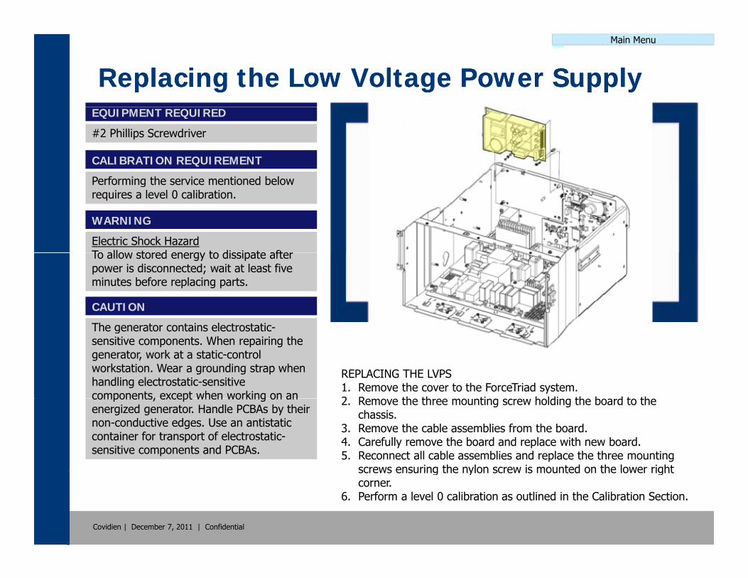
Main Menu
Replacing the Low Voltage Power SupplyReplacing the Low Voltage Power SupplyEQUIPMENT REQUIRED
#2 Phillips Screwdriver
CALIBRATION REQUIREMENT
Performing the service mentioned belowPerforming the service mentioned below requires a level 0 calibration.
WARNING
Electric Shock HazardTo allow stored energy to dissipate afterTo allow stored energy to dissipate after power is disconnected; wait at least five minutes before replacing parts.
CAUTION
The generator contains electrostatic
REPLACING THE LVPS1. Remove the cover to the ForceTriad system.2 R th th ti h ldi th b d t th
The generator contains electrostatic-sensitive components. When repairing the generator, work at a static-control workstation. Wear a grounding strap when handling electrostatic-sensitive components, except when working on an 2. Remove the three mounting screw holding the board to the
chassis.3. Remove the cable assemblies from the board.4. Carefully remove the board and replace with new board.5. Reconnect all cable assemblies and replace the three mounting
screws ensuring the nylon screw is mounted on the lower right
components, except when working on an energized generator. Handle PCBAs by their non-conductive edges. Use an antistatic container for transport of electrostatic-sensitive components and PCBAs.
Covidien | December 7, 2011 | Confidential
screws ensuring the nylon screw is mounted on the lower right corner.
6. Perform a level 0 calibration as outlined in the Calibration Section.
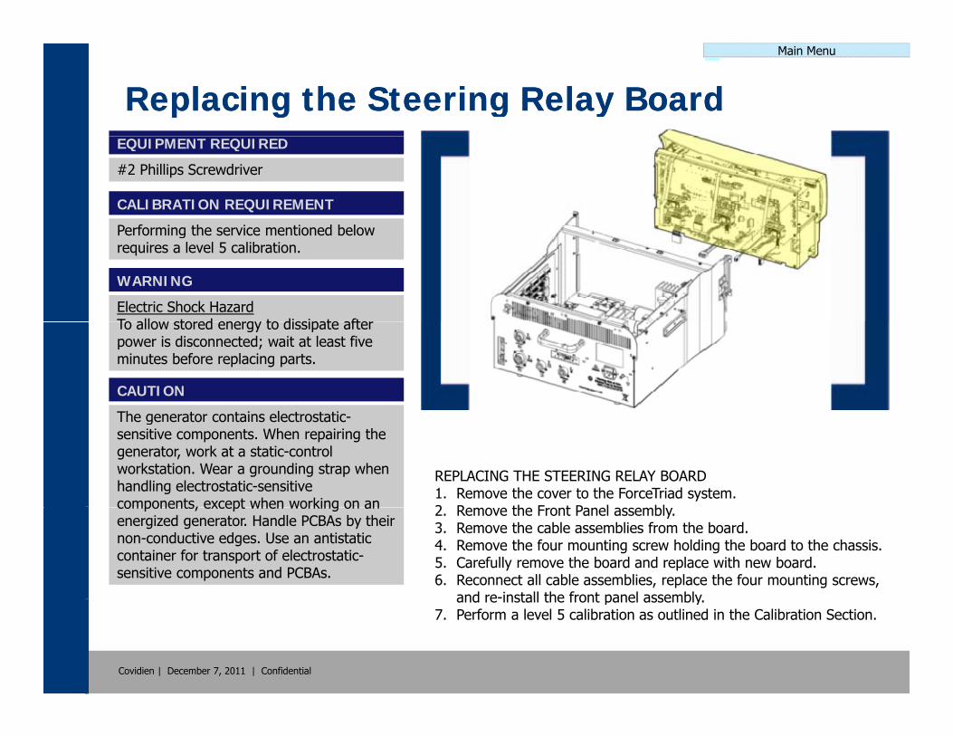
Main Menu
Replacing the Steering Relay BoardReplacing the Steering Relay BoardEQUIPMENT REQUIRED
#2 Phillips Screwdriver
CALIBRATION REQUIREMENT
Performing the service mentioned belowPerforming the service mentioned below requires a level 5 calibration.
WARNING
Electric Shock HazardTo allow stored energy to dissipate afterTo allow stored energy to dissipate after power is disconnected; wait at least five minutes before replacing parts.
CAUTION
The generator contains electrostatic
REPLACING THE STEERING RELAY BOARD1. Remove the cover to the ForceTriad system.2 R th F t P l bl
The generator contains electrostatic-sensitive components. When repairing the generator, work at a static-control workstation. Wear a grounding strap when handling electrostatic-sensitive components, except when working on an 2. Remove the Front Panel assembly.
3. Remove the cable assemblies from the board.4. Remove the four mounting screw holding the board to the chassis.5. Carefully remove the board and replace with new board.6. Reconnect all cable assemblies, replace the four mounting screws,
and re-install the front panel assembly
components, except when working on an energized generator. Handle PCBAs by their non-conductive edges. Use an antistatic container for transport of electrostatic-sensitive components and PCBAs.
Covidien | December 7, 2011 | Confidential
and re install the front panel assembly.7. Perform a level 5 calibration as outlined in the Calibration Section.

Main Menu
Replacing the System DisplaysReplacing the System DisplaysEQUIPMENT REQUIRED
#2 Phillips Screwdriver
CALIBRATION REQUIREMENT
Performing the service mentioned belowPerforming the service mentioned below requires a level 3 calibration.
WARNING
Electric Shock HazardTo allow stored energy to dissipate afterTo allow stored energy to dissipate after power is disconnected; wait at least five minutes before replacing parts.
CAUTION
The generator contains electrostatic
REPLACING THE DISPLAYS1. Remove the cover to the ForceTriad system.2 R th F t P l bl
The generator contains electrostatic-sensitive components. When repairing the generator, work at a static-control workstation. Wear a grounding strap when handling electrostatic-sensitive components, except when working on an 2. Remove the Front Panel assembly.
3. Remove the Steering Relay Board.4. Remove the four mounting screw holding the display to the
housing.5. Carefully remove the display and replace with new display.6 Replace the four mounting screws re-install the steering relay
components, except when working on an energized generator. Handle PCBAs by their non-conductive edges. Use an antistatic container for transport of electrostatic-sensitive components and PCBAs.
Covidien | December 7, 2011 | Confidential
6. Replace the four mounting screws, re install the steering relay board, and re-install the front panel assembly.
7. Perform a level 3 calibration as outlined in the Calibration Section.

Main Menu
Replacing the System Display CablesReplacing the System Display CablesEQUIPMENT REQUIRED
#2 Phillips Screwdriver
CALIBRATION REQUIREMENT
Performing the service mentioned belowPerforming the service mentioned below requires a level 3 calibration.
WARNING
Electric Shock HazardTo allow stored energy to dissipate afterTo allow stored energy to dissipate after power is disconnected; wait at least five minutes before replacing parts.
CAUTION
The generator contains electrostatic
REPLACING THE DISPLAY CABLES1. Remove the cover to the ForceTriad system.2 R th F t P l bl d St i R l b d
The generator contains electrostatic-sensitive components. When repairing the generator, work at a static-control workstation. Wear a grounding strap when handling electrostatic-sensitive components, except when working on an 2. Remove the Front Panel assembly and Steering Relay board.
3. Carefully remove the display cables and replace with new display cables.
4. Re-install the front panel assembly, steering relay board, and replace the cover.
5 Perform a level 3 calibration as outlined in the Calibration Section
components, except when working on an energized generator. Handle PCBAs by their non-conductive edges. Use an antistatic container for transport of electrostatic-sensitive components and PCBAs.
Covidien | December 7, 2011 | Confidential
5. Perform a level 3 calibration as outlined in the Calibration Section.
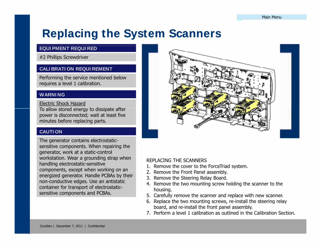
Main Menu
Replacing the System ScannersReplacing the System ScannersEQUIPMENT REQUIRED
#2 Phillips Screwdriver
CALIBRATION REQUIREMENT
Performing the service mentioned belowPerforming the service mentioned below requires a level 1 calibration.
WARNING
Electric Shock HazardTo allow stored energy to dissipate afterTo allow stored energy to dissipate after power is disconnected; wait at least five minutes before replacing parts.
CAUTION
The generator contains electrostatic
REPLACING THE SCANNERS1. Remove the cover to the ForceTriad system.2 R th F t P l bl
The generator contains electrostatic-sensitive components. When repairing the generator, work at a static-control workstation. Wear a grounding strap when handling electrostatic-sensitive components, except when working on an 2. Remove the Front Panel assembly.
3. Remove the Steering Relay Board.4. Remove the two mounting screw holding the scanner to the
housing.5. Carefully remove the scanner and replace with new scanner.6 Replace the two mounting screws re-install the steering relay
components, except when working on an energized generator. Handle PCBAs by their non-conductive edges. Use an antistatic container for transport of electrostatic-sensitive components and PCBAs.
Covidien | December 7, 2011 | Confidential
6. Replace the two mounting screws, re install the steering relay board, and re-install the front panel assembly.
7. Perform a level 1 calibration as outlined in the Calibration Section.
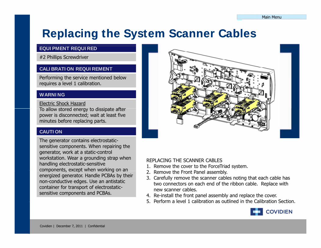
Main Menu
Replacing the System Scanner CablesReplacing the System Scanner CablesEQUIPMENT REQUIRED
#2 Phillips Screwdriver
CALIBRATION REQUIREMENT
Performing the service mentioned belowPerforming the service mentioned below requires a level 1 calibration.
WARNING
Electric Shock HazardTo allow stored energy to dissipate afterTo allow stored energy to dissipate after power is disconnected; wait at least five minutes before replacing parts.
CAUTION
The generator contains electrostatic
REPLACING THE SCANNER CABLES1. Remove the cover to the ForceTriad system.2 R th F t P l bl
The generator contains electrostatic-sensitive components. When repairing the generator, work at a static-control workstation. Wear a grounding strap when handling electrostatic-sensitive components, except when working on an 2. Remove the Front Panel assembly.
3. Carefully remove the scanner cables noting that each cable has two connectors on each end of the ribbon cable. Replace with new scanner cables.
4. Re-install the front panel assembly and replace the cover.5 Perform a level 1 calibration as outlined in the Calibration Section
components, except when working on an energized generator. Handle PCBAs by their non-conductive edges. Use an antistatic container for transport of electrostatic-sensitive components and PCBAs.
Covidien | December 7, 2011 | Confidential
5. Perform a level 1 calibration as outlined in the Calibration Section.
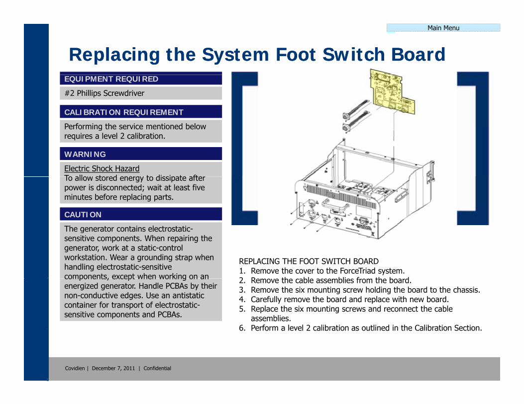
Main Menu
Replacing the System Foot Switch BoardReplacing the System Foot Switch BoardEQUIPMENT REQUIRED
#2 Phillips Screwdriver
CALIBRATION REQUIREMENT
Performing the service mentioned belowPerforming the service mentioned below requires a level 2 calibration.
WARNING
Electric Shock HazardTo allow stored energy to dissipate afterTo allow stored energy to dissipate after power is disconnected; wait at least five minutes before replacing parts.
CAUTION
The generator contains electrostatic
REPLACING THE FOOT SWITCH BOARD1. Remove the cover to the ForceTriad system.2 R th bl bli f th b d
The generator contains electrostatic-sensitive components. When repairing the generator, work at a static-control workstation. Wear a grounding strap when handling electrostatic-sensitive components, except when working on an 2. Remove the cable assemblies from the board.
3. Remove the six mounting screw holding the board to the chassis.4. Carefully remove the board and replace with new board.5. Replace the six mounting screws and reconnect the cable
assemblies.6 Perform a level 2 calibration as outlined in the Calibration Section
components, except when working on an energized generator. Handle PCBAs by their non-conductive edges. Use an antistatic container for transport of electrostatic-sensitive components and PCBAs.
Covidien | December 7, 2011 | Confidential
6. Perform a level 2 calibration as outlined in the Calibration Section.

Main Menu
Replacing the System FansReplacing the System FansEQUIPMENT REQUIRED
#2 Phillips Screwdriver
CALIBRATION REQUIREMENT
Performing the service mentioned belowPerforming the service mentioned below requires a level 0 calibration.
WARNING
Electric Shock HazardTo allow stored energy to dissipate afterTo allow stored energy to dissipate after power is disconnected; wait at least five minutes before replacing parts.
CAUTION
The generator contains electrostatic
REPLACING THE SYSTEM FANS1. Remove the cover to the ForceTriad system.2 R th F t P l bl d RF B d
The generator contains electrostatic-sensitive components. When repairing the generator, work at a static-control workstation. Wear a grounding strap when handling electrostatic-sensitive components, except when working on an 2. Remove the Front Panel assembly and RF Board.
3. Remove the mounting screw holding the fan(s) to the housing.4. Remove the fan(s) and replace with new fan(s).5. Replace the mounting screws, re-install the RF board, and re-
install the front panel assembly.6 Perform a level 0 calibration as outlined in the Calibration Section
components, except when working on an energized generator. Handle PCBAs by their non-conductive edges. Use an antistatic container for transport of electrostatic-sensitive components and PCBAs.
Covidien | December 7, 2011 | Confidential
6. Perform a level 0 calibration as outlined in the Calibration Section.

Main Menu
Replacing the System FusesReplacing the System FusesEQUIPMENT REQUIRED
#1 Flathead Screwdriver
CALIBRATION REQUIREMENT
Performing the service mentioned belowPerforming the service mentioned below requires a level 0 calibration.
WARNING
Electric Shock HazardTo allow stored energy to dissipate afterTo allow stored energy to dissipate after power is disconnected; wait at least five minutes before replacing parts.
CAUTION
The generator contains electrostatic
REPLACING THE SYSTEM FUSES1. Remove the fuse holder using the flathead screwdriver.2 R th f f th h ld
The generator contains electrostatic-sensitive components. When repairing the generator, work at a static-control workstation. Wear a grounding strap when handling electrostatic-sensitive components, except when working on an 2. Remove the fuses from the holder.
3. Replace the bad fuses as needed.4. Reinstall the fuse holder into the socket.5. Perform a level 0 calibration as outlined in the Calibration Section.
components, except when working on an energized generator. Handle PCBAs by their non-conductive edges. Use an antistatic container for transport of electrostatic-sensitive components and PCBAs.
Covidien | December 7, 2011 | Confidential
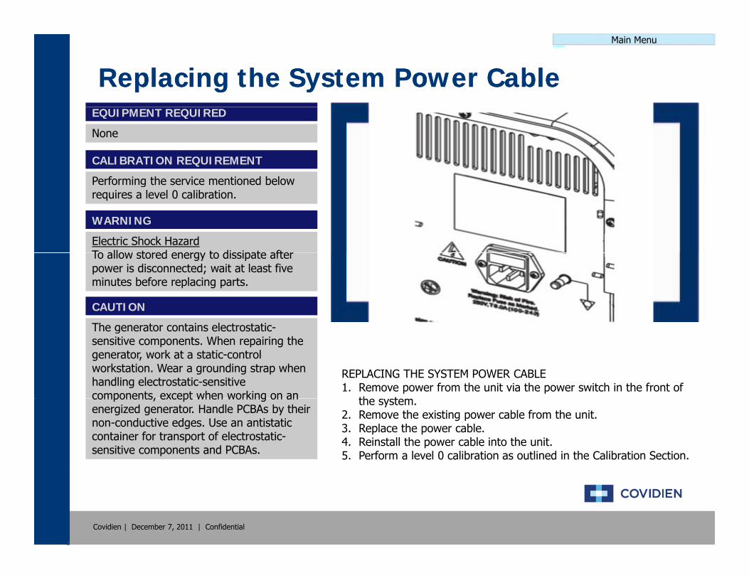
Main Menu
Replacing the System Power CableReplacing the System Power CableEQUIPMENT REQUIRED
None
CALIBRATION REQUIREMENT
Performing the service mentioned belowPerforming the service mentioned below requires a level 0 calibration.
WARNING
Electric Shock HazardTo allow stored energy to dissipate afterTo allow stored energy to dissipate after power is disconnected; wait at least five minutes before replacing parts.
CAUTION
The generator contains electrostatic
REPLACING THE SYSTEM POWER CABLE1. Remove power from the unit via the power switch in the front of
th t
The generator contains electrostatic-sensitive components. When repairing the generator, work at a static-control workstation. Wear a grounding strap when handling electrostatic-sensitive components, except when working on an the system.
2. Remove the existing power cable from the unit.3. Replace the power cable.4. Reinstall the power cable into the unit.5. Perform a level 0 calibration as outlined in the Calibration Section.
components, except when working on an energized generator. Handle PCBAs by their non-conductive edges. Use an antistatic container for transport of electrostatic-sensitive components and PCBAs.
Covidien | December 7, 2011 | Confidential
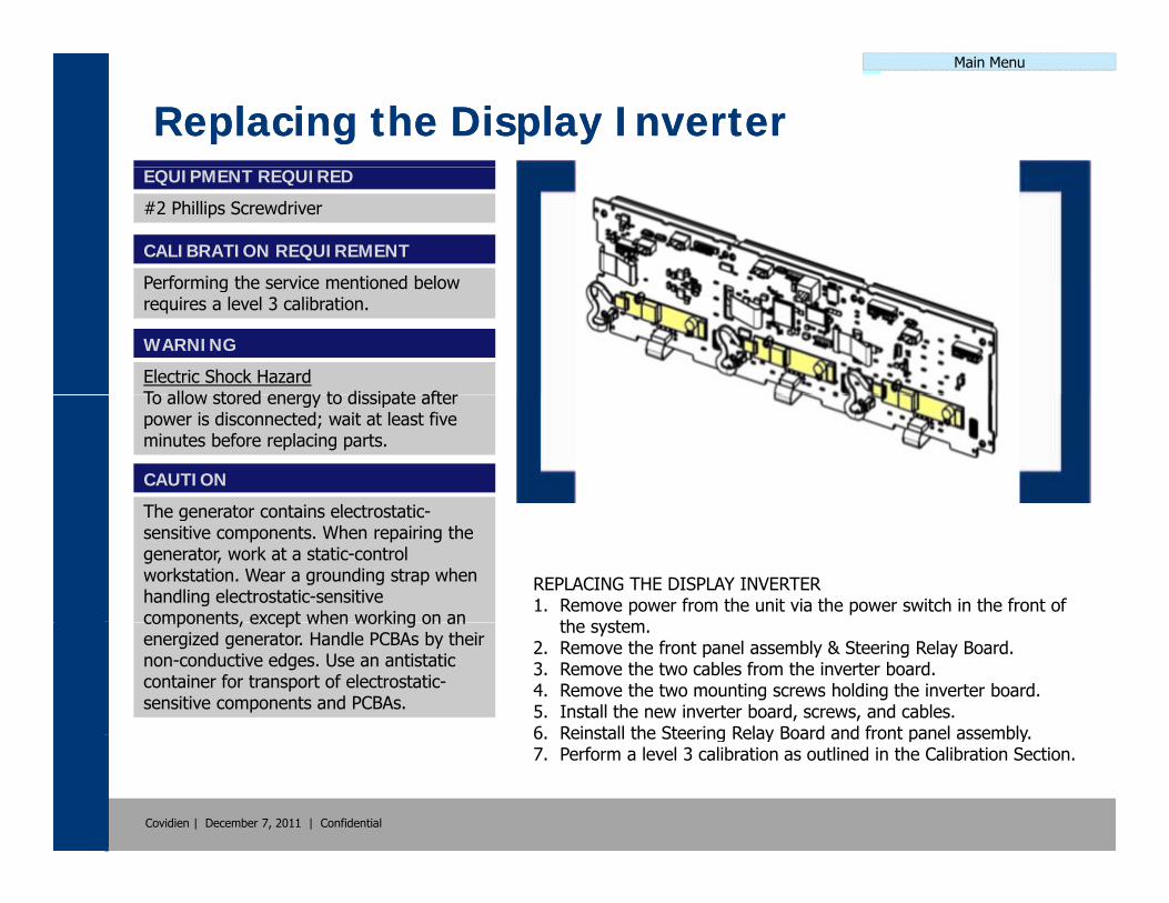
Main Menu
Replacing the Display InverterReplacing the Display InverterEQUIPMENT REQUIRED
#2 Phillips Screwdriver
CALIBRATION REQUIREMENT
Performing the service mentioned belowPerforming the service mentioned below requires a level 3 calibration.
WARNING
Electric Shock HazardTo allow stored energy to dissipate afterTo allow stored energy to dissipate after power is disconnected; wait at least five minutes before replacing parts.
CAUTION
The generator contains electrostatic
REPLACING THE DISPLAY INVERTER1. Remove power from the unit via the power switch in the front of
th t
The generator contains electrostatic-sensitive components. When repairing the generator, work at a static-control workstation. Wear a grounding strap when handling electrostatic-sensitive components, except when working on an the system.
2. Remove the front panel assembly & Steering Relay Board.3. Remove the two cables from the inverter board.4. Remove the two mounting screws holding the inverter board.5. Install the new inverter board, screws, and cables.6 Reinstall the Steering Relay Board and front panel assembly
components, except when working on an energized generator. Handle PCBAs by their non-conductive edges. Use an antistatic container for transport of electrostatic-sensitive components and PCBAs.
Covidien | December 7, 2011 | Confidential
6. Reinstall the Steering Relay Board and front panel assembly.7. Perform a level 3 calibration as outlined in the Calibration Section.

Main Menu
Periodic Safety CheckPeriodic Safety CheckThe periodic safety check is designed to inspect the ForceTriad system for proper functionality and to ensure that the safety features of the unit are intact. The following safety checks should be conducted once a year and recorded for future reference. Should the system fail to meet any of the checks and develops an error, refer the Error Code Definition & Troubleshooting section of this guide.
Safety Checks to be Performed1. Initial Inspection
2. System Self-Check
3 Calibration (if applicable)3. Calibration (if applicable)
4. Low voltage Power Supply (if applicable)
5. Audio Test
6. REM & Autobipolar Test
7. Cross Coupling Test
8. Power Delivery at Receptacle
9. Power Output Test
10. High Frequency Leakage
11 Safety Test & Valleylab ExchangeThe entire Preventive Maintenance procedure and checklist can be found
Covidien | December 7, 2011 | Confidential
11. Safety Test & Valleylab Exchange in the system service manual with a date code later than 06/2011.