forces in more than one dimension - university of...
TRANSCRIPT

Forces in Morethan One Dimension
��
��34.2
IntroductionThis Section looks at forces on objects resting or moving on inclined planes and forces on objectsmoving along curved paths. The previous ideas are exploited in example calculations related topassenger sensations of forces on amusement rides.
'
&
$
%
PrerequisitesBefore starting this Section you should . . .
• be able to use vectors and to carry out scalarand vector products
• be able to use Newton’s laws to describe andmodel the motion of particles
• be able to use coordinate geometry to studycircles and parabolas
• be able to use calculus to differentiate andintegrate polynomials
'
&
$
%
Learning OutcomesOn completion you should be able to . . .
• compute frictional forces on static andmoving objects on inclined planes and onobjects moving at constant speed aroundbends
• calculate the forces experienced bypassengers in vehicles moving along straight,curved and inclined tracks
34 HELM (2008):Workbook 34: Modelling Motion
®
1. Forces in two or three dimensions
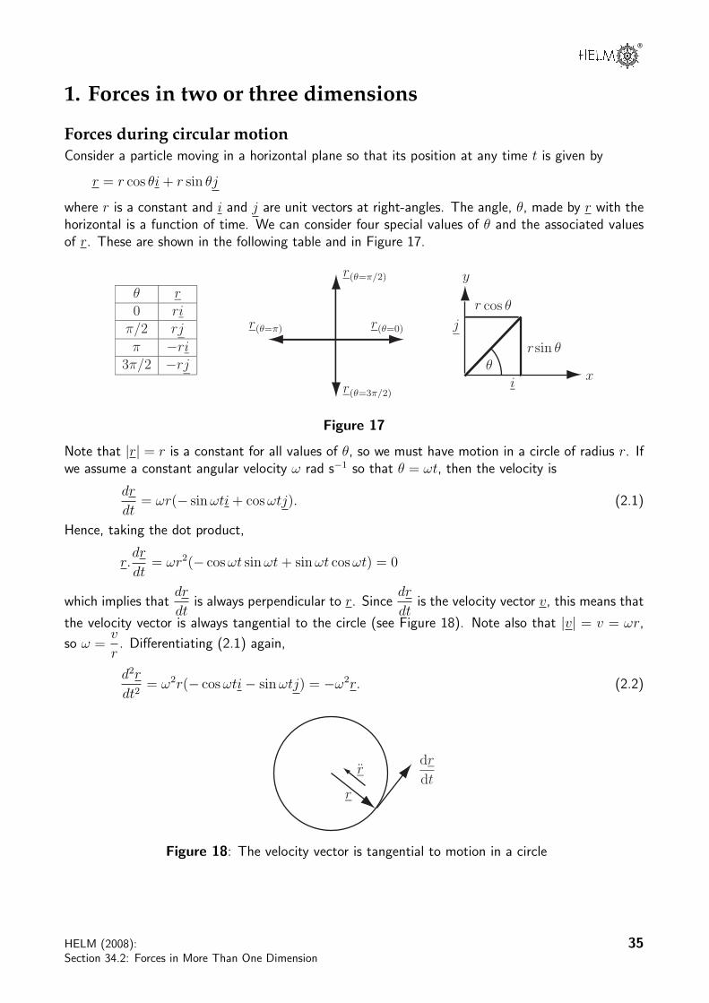
Forces during circular motionConsider a particle moving in a horizontal plane so that its position at any time t is given by
r = r cos θi + r sin θj
where r is a constant and i and j are unit vectors at right-angles. The angle, θ, made by r with thehorizontal is a function of time. We can consider four special values of θ and the associated valuesof r. These are shown in the following table and in Figure 17.
x
y
i
j
θsin θ
cos θ
r
r
r(θ=0)
r(θ=π/2)
r(θ=π)
r(θ=3π/2)
θ r0 ri
π/2 rj
π −ri3π/2 −rj
Figure 17
Note that |r| = r is a constant for all values of θ, so we must have motion in a circle of radius r. Ifwe assume a constant angular velocity ω rad s−1 so that θ = ωt, then the velocity is
dr
dt= ωr(− sin ωti + cos ωtj). (2.1)
Hence, taking the dot product,
r.dr
dt= ωr2(− cos ωt sin ωt + sin ωt cos ωt) = 0
which implies thatdr
dtis always perpendicular to r. Since
dr
dtis the velocity vector v, this means that
the velocity vector is always tangential to the circle (see Figure 18). Note also that |v| = v = ωr,
so ω =v
r. Differentiating (2.1) again,
d2r
dt2= ω2r(− cos ωti− sin ωtj) = −ω2r. (2.2)
r
r
dr
dt
Figure 18: The velocity vector is tangential to motion in a circle
HELM (2008):Section 34.2: Forces in More Than One Dimension
35

Equation (2.2) means that the second derivative,d2r
dt2, which represents the acceleration a, acts along
the radius towards the centre of the circle and is perpendicular todr
dt.
The magnitude of the velocity (the speed) is constant and the acceleration, a, is associated withthe changing direction of the velocity. The force must act towards the centre of the circle to achieve
this change in direction around the circle. Since a(t) = −ω2r(t) , where ω =v
r, we see that the
acceleration acts towards the centre of the circle and has a magnitude given by a =v2
r. This is a
special example of the fact that forces in the direction of motion cause changes in speed, while forcesat right-angles to the direction of motion cause changes in direction.
When a particle is moving at constant speed around a circle on the end of a rope, then the forcedirected towards the centre is supplied by the tension in the rope. When a vehicle moves at constantspeed around a circular bend in a road, then the force directed towards the centre of the bend issupplied by sideways friction of the tyres with the road. If the vehicle of mass m were to be pushed ordragged sideways by a steady force then it would be necessary to overcome the frictional force. Thisforce depends on the normal reaction R, which is equal and opposite to the weight of the vehicle(mg). The friction force is given by µmg where µ is the coefficient of friction and it must at leastequal the required force towards the centre of the bend to avoid skidding. So, we must have
µmg ≥ mv2
r. (2.3)
Example 9A car of mass 900 kg drives around a roundabout of radius 15 m at a constantspeed of 10 m s−1.
(a) Draw a vector diagram showing the forces on the car in the verticaland sideways directions.
(b) What is the magnitude of the force directed towards the centre of thebend?
(c) What is the friction force between the car and the road?
(d) What does this imply about the minimum value of the coefficient offriction?
mv2
r
R
W
F
mg
Figure 19: Forces on a vehicle negotiating a circular bend at constant speed
36 HELM (2008):Workbook 34: Modelling Motion

®
Solution
(a) See Figure 19. (In addition to the sideways friction involved in cornering, there will be a netforce causing forward motion which is generated by the vehicle engine and exerted through frictionbetween the tyres and the road.) The forces are shown as if they act at the centre of the vehicle,since the vehicle is being treated as a particle. Strictly speaking, the frictional forces on a roadvehicle should be considered to act at the tyre/road contact and there will be differences betweenthe forces at each wheel.
(b) The magnitude of the force is obtained by using
mv2
r=
900× 100
15= 6000.
So the magnitude of the force acting towards the centre of the roundabout is 6000 N.
(c) The sideways force provided by friction is |F | = µ|R|. In this case |R| = mg.
(d) Consequently we must have µmg ≥ 6000, that is
µ ≥ 6000
900× 9.81= 0.68.
Task
Suppose that the coefficient of friction between the car and the ground in dryconditions is 0.96.
(a) At what speed could the car drive around the roundabout without skidding?
Your solution
AnswerEquation (2.3) on page 36 states that for the vehicle to go round the bend just without skidding
mv2
r= µmg, or
v2
r= µg.
In this case, the maximum speed is required, so the relationship is best rearranged into the formv =
√µgr. The values to be substituted are µ = 0.96, g = 9.81 and r = 15, so
v =√
0.96× 9.81× 15 = 11.9.
So the car will skid if it drives round the roundabout at more than 11.9 m s−1 (nearly 27 mph).
HELM (2008):Section 34.2: Forces in More Than One Dimension
37

(b) What would be the radius of roundabout that would enable a car to drive around it safely in dryconditions at 30 m s−1 (nearly 70 mph)?
Your solution
AnswerFor this part of the question, the speed around the roundabout is known and the safe radius is tobe found. Further rearrangement of the expression used in part (a) gives
r =v2
µg.
Hence
r =302
0.96× 9.81= 95.6.
In reality drivers should not be exactly at the limits of the friction force while going round theroundabout. There should be some safety margin. So the roundabout should have a radius of atleast 100 m to allow cars to drive round it at 30 m s−1.
(c) What would be the safe radius of this roundabout when conditions are wet so that the coefficientof friction between the car and the road is reduced by a factor of 2?
Your solution
AnswerThe form of the equation used in part (b) indicates that if the coefficient of friction is halved (to0.48) by wet conditions, then the safe radius should be doubled.
38 HELM (2008):Workbook 34: Modelling Motion

®
When a cyclist or motorcyclist negotiates a circular bend at constant speed, the forces experiencedat the points of contact between the tyres and the road are a frictional force towards the centre ofthe bend and the upward reaction to the combined weight of the cyclist and the cycle (see Figure20). These forces can be combined into a resultant that acts along an angle to the vertical. Supposethat the combined mass is m and that the coefficient of friction between the tyres and road surfaceis µ.
i
j
θ
reaction
friction
Figure 20Forces on cycle tyres and the angle for cyclist comfort on a circular bend.
The net driving force is ignored.
The total force vector may be written
F = mg(µi + j)
and the angle θ is given by
tan θ =µmg
mg= µ so that θ = tan−1 µ.
Also, as argued previously (Equation (2.3)), we must have µ ≥ v2
gr, which means that
θ ≥ tan−1
(v2
gr
)To be comfortable while riding, the cyclist likes to feel that the total force is vertical. So whennegotiating the bend, the cyclist tilts towards the bend so that the resultant force acts along a ‘newvertical’.
HELM (2008):Section 34.2: Forces in More Than One Dimension
39
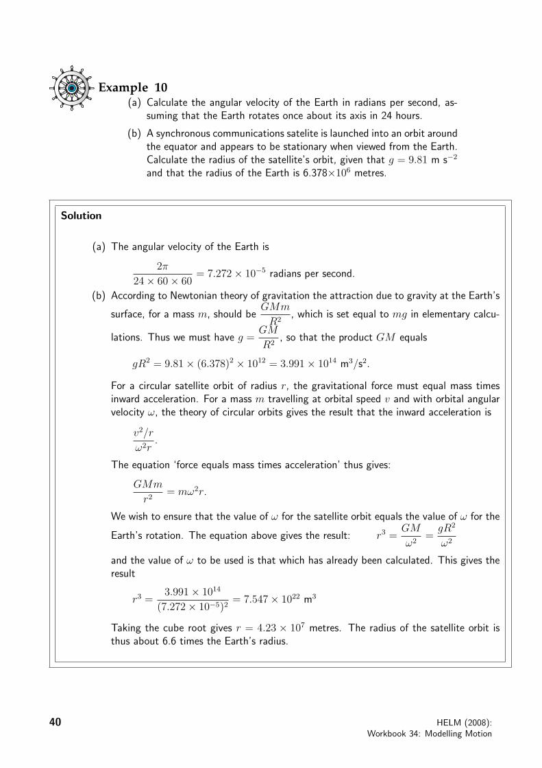
Example 10(a) Calculate the angular velocity of the Earth in radians per second, as-
suming that the Earth rotates once about its axis in 24 hours.
(b) A synchronous communications satelite is launched into an orbit aroundthe equator and appears to be stationary when viewed from the Earth.Calculate the radius of the satellite’s orbit, given that g = 9.81 m s−2
and that the radius of the Earth is 6.378×10⁶ metres.
Solution
(a) The angular velocity of the Earth is
2π
24× 60× 60= 7.272× 10⁻⁵ radians per second.
(b) According to Newtonian theory of gravitation the attraction due to gravity at the Earth’s
surface, for a mass m, should beGMm
R2, which is set equal to mg in elementary calcu-
lations. Thus we must have g =GM
R2, so that the product GM equals
gR2 = 9.81× (6.378)2 × 1012 = 3.991× 10¹⁴ m3/s2.
For a circular satellite orbit of radius r, the gravitational force must equal mass timesinward acceleration. For a mass m travelling at orbital speed v and with orbital angularvelocity ω, the theory of circular orbits gives the result that the inward acceleration is
v2/r
ω2r.
The equation ‘force equals mass times acceleration’ thus gives:
GMm
r2= mω2r.
We wish to ensure that the value of ω for the satellite orbit equals the value of ω for the
Earth’s rotation. The equation above gives the result: r3 =GM
ω2=
gR2
ω2
and the value of ω to be used is that which has already been calculated. This gives theresult
r3 =3.991× 10¹⁴
(7.272× 10⁻⁵)2= 7.547× 10²² m3
Taking the cube root gives r = 4.23 × 10⁷ metres. The radius of the satellite orbit isthus about 6.6 times the Earth’s radius.
40 HELM (2008):Workbook 34: Modelling Motion

®
Task
The pedals on a bicycle drive the chain ring, which moves the chain. The chainpasses around the sprocket (gear wheel) attached to the rear wheel and hence therear wheel and the bicycle are driven (see diagram). There are cog teeth of equalwidth (d) cut into both the chain ring and the sprocket. If there are n1 teeth in thechain ring and n2 teeth in the sprocket then n1/n2 is the gear ratio. Suppose thatthe radii of the chain ring, sprocket and rear wheel are r1, r2 and r respectivelyand that the angular velocities of the chain ring and rear wheel are ω1 and ω2
respectively.
sprocket
chain ringr
r2
r1
Bicycle drive system.
(a) Write down an expression for the velocity (u) of the bicycle in terms of the angular velocity ofthe rear wheel:
Your solution
Answer
u = rω2
(b) Write down the relationship between the velocity of the sprocket and the velocity of the chainring:
Your solution
Answer
r1ω1 = r2ω2
HELM (2008):Section 34.2: Forces in More Than One Dimension
41

(c) Write down expressions for the circumference of the chain ring and that of the sprocket in termsof the teeth width and number of teeth:
Your solution
Answer
2πr1 = n1d, 2πr2 = n2d
(d) Hence derive a relationship between the angular velocities and the gear ratio:
Your solution
Answer
From (b) and (c),n1d
2πω1 =
n2d
2πω2 or n1ω1 = n2ω2, so gear ratio =
ω2
ω1
(e) Calculate the speed of the bicycle if the cyclist is pedalling at one revolution per second, theradius of the rear wheel is 0.34 m and the gear ratio is 4:
Your solution
Answer
From (a) and (d), u = r(n1/n2)ω1 = 0.34(4)(2π) = 8.55 m s−1 (about 19 mph).
42 HELM (2008):Workbook 34: Modelling Motion

®
2. Amusement ridesThe design of amusement rides is intended to make the forces experienced by passengers as excitingas possible. High speeds are not enough. The production of accelerations of up to four timesthat due to gravity and occasional feelings of near-weightlessness are deliberate design goals. Theaccelerations may not only be in the forward or backward directions from the passengers’ perspectivebut also sideways. Sideways accelerations are more limited than backwards or forwards ones, sincethey are less welcome to passengers and also pose particular problems for the associated structures.Upward accelerations of greater than g are avoided because of the safety risk and the need forreliable constraints to prevent passengers ‘floating’ out of the carriages. The rates at which theforces, or accelerations, change are important in producing the overall sensation also. The rateof change of acceleration is called jerk. Even the rate of change of jerk, called jounce, may beof interest. On roller-coasters the height, the tightness and the twistiness of turns in the trackare the main parameters that influence the thrill of riding on them. Another factor that relatesto thrill or discomfort is the degree of mismatch between what is observed and what is felt. Forexample it is odd to feel as though one’s weight is acting in some other direction than the perceivedvertical. In this regard the magnitude of the force that is experienced may not be as important as itsdirection. Although we consider only two dimensions in this Workbook, the design of roller-coastersrequires calculations and considerations in 3D. We shall consider some particular examples of forcesexperienced by passengers. We start by exploring the forces that contribute to what we feel whenriding in a vehicle. Then we shall look at the forces experienced by passengers on amusement ridesranging from rotors to roller-coasters.
R
W
Figure 21: Forces on a seated passengerFearsome forces
The experiences we have on amusement rides include those of being subjected to linear and sidewaysaccelerations that are sensed by the balancing system close to our ears and can make us feel giddy.Potentially more ‘enjoyable’ are sensations of unfamiliar compressive forces that act on our bodiesthrough the vehicle in which we are travelling.
F
N
W
Figure 22: Forces when seated and being accelerated horizontally
Imagine that you are sitting on a stool, which is sufficiently tall so that your feet are not touching theground. What do you feel? Your weight is acting vertically downward. However you feel an upwardforce, which is the normal reaction of the stool to your weight. This reaction is pushing you upward(see Figure 21). Of course the total force on you is zero. Consequently there is a difference in this
HELM (2008):Section 34.2: Forces in More Than One Dimension
43

case between the total force on you, which includes gravity, and the force that you experience whichexcludes gravity.
On the other hand if you are sitting facing forwards in a vehicle that is accelerating forwards on a flattrack then you will experience the same acceleration as the vehicle, through the seat which pushesyou forwards (see Figure 22). The forward force from the seat combines with the normal reaction togive a resultant that is not vertical. This simple example suggests that the force experienced by apassenger during an amusement ride can be calculated by adding up all the component forces exceptfor the passenger’s weight.
Example 11(a) Calculate the horizontal and vertical components of the force F experienced bya passenger of mass 100 kg seated in a rollercoaster carriage that starts from restand moves in a straight line on a flat horizontal track with a constant accelerationsuch that it is moving at 40 m s−1 after 5 s.
(b) Deduce the magnitude and direction of the force experienced by the passenger.
Solution
(a) Consider first the acceleration of the passenger’s seat. The coordinate origin is chosen atthe start of motion. The x-axis is chosen along the direction of travel, with unit vectori, and the y-axis is vertical with y positive in the upward direction, with unit vector j.The acceleration a may be calculated from
a =dv
dt= ai
or v = ati + c. When t = 0, v = 0, so c = 0. When t = 5, v = 40i. Hence 40 = 5a ora = 8. The acceleration in the direction of travel is 8 m s−2, so the component of theforce F in the direction of travel is given by ma = 100×8 N = 800 N. The seat exerts aforce on the passenger that balances the force due to gravity i.e. the passenger’s weight.So the vertical component of the force on the passenger is mg = 100 × 9.81 N = 981N. Hence the total force experienced by the passenger may be expressed as
F = 800i + 981j.
This is the total force exerted by the vehicle on the passenger. The force exerted by thepassenger on the vehicle is the direct opposite of this i.e. −800i− 981j.
(b) The magnitude of the total force is√
8002 + 9812 N ≈ 1300 N and the total forceexperienced by the passenger is at an angle with respect to the horizontal equal totan−1(981/800) ≈ 51◦.
Here we considered the sudden application of a constant acceleration of 8 m s−2 whichwill cause quite a jerk for the passengers at the start. On some rides the accelerationmay be applied more smoothly.
44 HELM (2008):Workbook 34: Modelling Motion
®
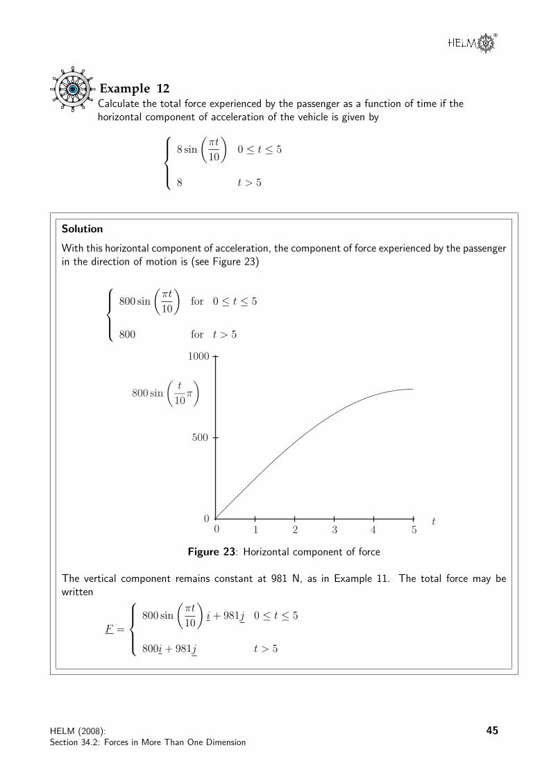
Example 12Calculate the total force experienced by the passenger as a function of time if thehorizontal component of acceleration of the vehicle is given by
8 sin
(πt
10
)0 ≤ t ≤ 5
8 t > 5
Solution
With this horizontal component of acceleration, the component of force experienced by the passengerin the direction of motion is (see Figure 23)
800 sin
(πt
10
)for 0 ≤ t ≤ 5
800 for t > 5
800 sin
(t
10π
)
01 2 3 4 5
500
1000
0t
Figure 23: Horizontal component of force
The vertical component remains constant at 981 N, as in Example 11. The total force may bewritten
F =
800 sin
(πt
10
)i + 981j 0 ≤ t ≤ 5
800i + 981j t > 5
HELM (2008):Section 34.2: Forces in More Than One Dimension
45
Task
The idea of an amusement ride called the ‘Rotor’ is to whirl passengers around ina cylindrical container at increasing speed. When the rotation is sufficiently fastthe floor is lowered but the passengers remain where they are supported by frictionagainst the wall. Given a rotor radius of 2.2 m and a coefficient of friction of 0.4calculate the minimum rate of revolution when the floor may be lowered.
Your solution
AnswerThe reaction of the wall on the passenger will have the same magnitude as the force causing motion
in a circle i.e.mv2
r= R. The vertical friction force between the passenger and the wall is µR.
The passenger of mass will remain against the wall when the floor is lowered if µR ≥ mg. Hence
it is required thatµmv2
r≥ mg or v ≥
√rg
µ. Since v = ωr, where ω is the angular velocity, the
minimum required angular velocity is ω =
√g
µrand the corresponding minimum rate of revolution
n =ω
2π
√g
µr. Hence with r = 2.2 and µ = 0.4, the rate of revolution must be at least 0.53 revs
per sec or at least 32 revs per min.
46 HELM (2008):Workbook 34: Modelling Motion

®
Task
In an amusement ride called the ‘Yankee Flyer’, the passengers sit in a ‘boat’,which stays horizontal while executing a series of rotations on an arm about afixed centre. Given that the period of rotation is 2.75 s, calculate the radius ofrotation that will give rise to a feeling of near weightlessness at the top of eachrotation.
Your solution
AnswerTo achieve a feeling of ‘near-weightlessness’ near the top of the rotation, the force on the passengertowards the centre of rotation must be nearly equal and opposite to the reaction force of the seat
on the passengers i.e.mv2
r= mg. This means that r =
v2
g. Since v = ωr, this requires that
r =g
ω2. The period T =
2π
ω= 2.75 s, so ω = 2.285 rad s−1. Hence r = 1.879 m.
Example 13An amusement ride carriage moves along a track at constant velocity in the hori-zontal (x-) direction. It encounters a bump of horizontal length L and maximumheight h with a profile in the vertical plane given by
y(x) =h
2
(1− cos
2πx
L
), 0 ≤ x ≤ L.
Calculate the variation of the vertical component of force exerted on a passengerby the seat of the carriage with horizontal distance (x) as it moves over the bump.
HELM (2008):Section 34.2: Forces in More Than One Dimension
47

Solution
y(x)
x0
1
2
20 40 60 80 100
Figure 24: Profile of the bump
Figure 24 shows a graph of y(x) against x for h = 2 and L = 100. Since the component of velocityof the vehicle in the x-direction is constant, then after time t, the horizontal distance moved, x, isgiven by x = ut as long as x is measured from the location at t = 0. Consequently the y-coordinatemay be written in terms of t rather than x, giving
y(t) =h
2
(1− cos
2πut
L
), 0 ≤ t ≤ L
u.
The vertical component of velocity is given by differentiating this expression for y(t) with respectto t.
y(t) =h
2
2πu
Lsin
(2πut
L
)=
hπu
Lsin
(2πut
L
).
The vertical acceleration is given by differentiating this again.
y(t) =hπu
L
2πu
Lcos
(2πut
L
)=
2hπ2u2
L2cos
(2πut
L
).
Two forces contribute to the vertical force exerted by the seat on the passenger: the constantreaction to the passenger’s weight and the variable vertical reaction associated with motion over thebump. The magnitude of the total vertical force R N exerted on the passenger by the seat is givenby
R = mg + my(t) = mg + m2hπ2u2
L2cos
(2πut
L
)= mg
(1 +
2hπ2u2
gL2cos
(2πut
L
)).
Some horizontal force may be needed to keep the vehicle moving with a constant horizontal com-ponent of velocity and ensure that the net horizontal component of acceleration is zero. Since thehorizontal component of velocity is constant, there is no horizontal component of acceleration andno net horizontal component of force. Consequently R = Rj represents the total force exerted onthe passenger. Figure 25 shows a graph of R/mg for h = 2 m, L = 100 m and u = 20 m s−1.
Rmg
x0 20 40 60 80 100
0.8
1.0
1.2
Figure 25: Vertical force acting on passenger
48 HELM (2008):Workbook 34: Modelling Motion

®
Banked tracksLook back near the end of Section 34.2 subsection 1 which considered the forces on a cyclist trav-elling around a circular bend of radius R. We were concerned with the way in which cyclists andmotorcyclists bank their vehicles to create a ‘new vertical’ along the direction of the resultant force.This counteracts the torque that would otherwise encourage the rider to fall over when cornering.Clearly, passengers in four wheeled vehicles, railway trains and amusement park rides are not able tobank or tilt their vehicles to any significant extent. However what happens if the road or track is
banked instead? If the road or track is tilted or banked at angle θ = tan−1
(v2
gr
)to the horizontal,
then, at speed v around the circular bend, it is possible to obtain the same result as that achievedby tilting the cycle or motorcycle (see Figure 26).
reactionresultant
friction
Banked roador track
Resultant force
θ
i
jθ
θ
Figure 26: Equivalence of tilted cyclists and banked roads
Example 14Calculate the angle at which a track should be tilted so that passengers in a railwaycarriage moving at a constant speed of 20 m s−1 around a bend of radius 100 mfeel the resultant ‘reaction’ force as though it were acting vertically through theircentre line.
Solution
The angle of the resultant force on passengers if the track were horizontal is given by
θ = tan−1
(v2
gr
),
where v = 20, r = 100 and g = 9.81.
Hence θ = 22.18◦ and the track should be tilted at 22.18◦ to the horizontal for the resultant forceto act at right-angles to the track.
HELM (2008):Section 34.2: Forces in More Than One Dimension
49

Example 15The first three seconds of an amusement ride are described by the position coor-dinates
x(t) = 10− 10 cos(0.5t)y(t) = 20 sin(0.5t)
(0 < t < 3)
in the horizontal plane where x and y are in m.
(a) Calculate the velocity and acceleration vectors.
(b) Hence deduce the initial magnitude and direction of the accelerationand the magnitude and direction of the acceleration after three seconds.
Solution
y(t)
x(t)0 5 10
0
10
20
Figure 27: Path of ride
In this Example, the path of the ride is not circular (see Figure 27). In fact it is part of an ellipse.If we choose unit vectors i along the x-direction and j along the y-direction, and origin at t = 0,the position vector may be written
r(t) = (10− 10 cos(0.5t))i + 20 sin(0.5t)j.
The velocity vector is obtained by differentiating this with respect to time.
v(t) = 5 sin(0.5t)i + 10 cos(0.5t)j.
The acceleration vector is obtained by differentiating again.
a(t) = 2.5 cos(0.5t)i− 5 sin(0.5t)j
At t = 0, a(t) = 2.5i. So the initial acceleration is 2.5 m s−2 in the x-direction.
At t = 3, a(t) = 2.5 cos(1.5)i− 5 sin(1.5)j = 0.177i− 0.487j.
So after three seconds the acceleration is 4.99 m s−2 at an angle of 88◦ in the negative y-direction.This means a sideways acceleration of about 0.5g towards the inside of the track and almost atright-angles to it.
50 HELM (2008):Workbook 34: Modelling Motion

®
Engineering Example 1
Car velocity on a bend
Problem in words
A road has a bend with radius of curvature 100 m. The road is banked at an angle of 10◦. At whatspeed should a car take the bend in order not to experience any (net) side thrust on the tyres?
Mathematical statement of the problem
Figure 28 below shows the forces on the car.
10!
mg
R
mv2
r
Figure 28: A vehicle rounding a banked bend in the road.
In the figure R is the reactive force of the ground acting on the vehicle. The vehicle provides a forceof mg, the weight of the vehicle, operating vertically downwards. The vehicle needs a sideways force
ofmv2
rin order to maintain the locally circular motion.
We have used the following assumptions:
(a) The sideways force needed on the vehicle in order to maintain it in circular motion (called the
centripetal force) ismv2
rwhere r is the radius of curvature of the bend, v is the velocity and m the
mass of the vehicle.
(b) The only force with component acting sideways on the vehicle is the reactive force of the ground.This acts in a direction normal to the ground. (That is, we assume no frictional force in a sidewaysdirection.)
(c) The force due to gravity of the vehicle is mg, where m is the mass of the vehicle and g is theacceleration due to gravity (≈ 9.8 m s−2). This acts vertically downwards.
The problem we need to solve is ‘What value of v would be such that the component of the reactive
force of the ground exactly balances the sideways force ofmv2
r?’ This will give us the maximum
velocity at which the vehicle can take the bend.
HELM (2008):Section 34.2: Forces in More Than One Dimension
51

Mathematical analysis
We can split the reactive force of the ground into two components. One component is in thehorizontal direction and the other in a vertical direction as in the following figure:
10!
R
R cos 10!
R sin 10!
Figure 29: Reaction forces on the car
The force ofmv2
rmust be provided by a component of the reactive force in the horizontal direction
i.e.
R sin(10◦) =mv2
r(1)
However the reactive force must balance the force due to gravity in the vertical direction therefore
R cos(10◦) = mg (2)
We need to find v from the above equations. Dividing Equation (1) by Equation (2) gives
tan(10◦) =v2
rg⇒ v2 = rg tan(10◦)
We are given that the radius of curvature is 100 m and that g ≈ 9.8 m s−2. This givesv2 ≈ 100× 9.8× 0.17633⇒ v2 ≈ 172.8⇒ v ≈ 13.15 m s−1 (assuming v is positive)
Interpretation
We have found that the maximum speed that the car can take the bend in order not to experienceany side thrust on the tyres is 13.15 m s−1. This is 13.15 × 60 × 60/1000 kph = 47.34 kph. Inpractice, the need for a margin of safety would suggest that the maximum speed round the bendshould be 13 m s−1.
52 HELM (2008):Workbook 34: Modelling Motion
®
Exercises
1. A bend on a stretch of railway track has a radius of 200 m. The maximum sideways force onthe train on this bend must not exceed 0.1 of its weight.
(a) What is the maximum possible speed of the train on this bend?
(b) How far before this bend should a train travelling at 30 m s−1 begin to decelarate giventhat the maximum braking force of the train is 0.2 of its weight?
(c) What modelling assumptions have you made? Comment on their validity.
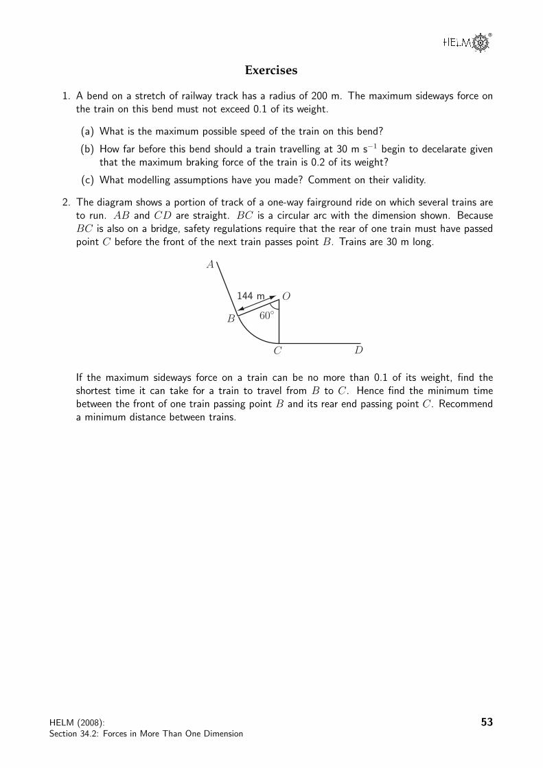
2. The diagram shows a portion of track of a one-way fairground ride on which several trains areto run. AB and CD are straight. BC is a circular arc with the dimension shown. BecauseBC is also on a bridge, safety regulations require that the rear of one train must have passedpoint C before the front of the next train passes point B. Trains are 30 m long.
144 m
A
B
C D
60!
O
If the maximum sideways force on a train can be no more than 0.1 of its weight, find theshortest time it can take for a train to travel from B to C. Hence find the minimum timebetween the front of one train passing point B and its rear end passing point C. Recommenda minimum distance between trains.
HELM (2008):Section 34.2: Forces in More Than One Dimension
53

Answers
1. (a) According to Equation (2.2) on page 35, during travel round the bend the sideways forceon the train is given by
Mrω2 =Mv2
r
The weight of the train is Mg. Given thatMv2
r≤ 0.1Mg, the maximum possible speed,
vmax, is given by vmax =√
0.1rg.
Using r = 200 m and g = 9.81 m s−2, this implies that vmax = 14.0 m s−1 to 3 s.f.
(b) Given initial speed is 30 m s−1, and final speed is 14 m s−1 and maximum braking forceis 0.2 Mg, implying acceleration is −0.2g. Then, using the formula ‘v2 = u2 + 2as’,where u is initial speed, v its final speed, a is acceleration and s is distance travelled,gives
20g = 900− 0.4gs or s = 179.358 m.
This suggests that braking should begin about 180 m before the start of the bend.
(c) Assumptions include constant maximum braking, negligible thinking time and no skid-ding.
2. The shortest time on the circular bend will be taken when the train is moving at the maximumpossible speed.
This will occur whenMv2
r= 0.1Mg. If r = 144 m and g = 9.81 m s−2, this implies
vmax = 11.885 m s−1.
The length of BC is 144π
3= 150.796 m.
The time taken for any point on the train to move from B to C is150.796
11.885= 12.687 s.
So, given that the length of each train is 30 m, to make sure that the rear of one train haspassed C before the front of the next train arrives at B, a minimum time between the trains
of (12.687 +30
11.885) s = 15.212 s is required. After including a small safety margin, each
train should be 16 s apart. Assuming that the trains are moving at a constant speed of 11.885m s−1, this implies that they should be at least 190 m apart.
54 HELM (2008):Workbook 34: Modelling Motion