force analysis of geneva wheel and face cam used in … 5/n046057388.pdf · due to this geneva...
TRANSCRIPT
Ashwin C Gowda et al Int. Journal of Engineering Research and Applications www.ijera.com
ISSN : 2248-9622, Vol. 4, Issue 6( Version 5), June 2014, pp.73-88
www.ijera.com 73 | P a g e
Force Analysis of Geneva Wheel and Face Cam Used In Automat
Madhoo G 1, Muhammed Sameer
2, Mohsin Ali
3, Ashwin C Gowda
4
1 Student Department of Machine Design , Ghousia College of Engineering ,Ramanagaram -562159
2 Specialist ATMO -06, BOSCH Ltd Adugodi, Bangalore -560030
3Assistant Professor Department of Mechanical Engineering, Ghousia College of Engineering, Ramanagaram
562159 4Assistant Professor Department of Computer Aided Engineering, Visvesvaraya Technological University,
Center for post graduate studies, Bangalore-560072
ABSTRACT
Glazerol Automat is a dedicated machine used in the Insulator pre assembly line. This automat is driven using
single motor for different operations. Here the focus is on two main parts they are Geneva wheel and Face cam
which are used for their respective operations. Geneva Wheel is used to index the drum which consists of 96
spindles. Due to this Geneva mechanism each of the spindles will hold the ceramic body when the drum is being
indexed. Due to which there is a force which is generated in the Geneva wheel in maximum and minimum
position. Face cam which is used while indexing the work piece carrier There are 2 tangential forces which are
acting, one at the indexing side and the other at the driving side /cam side. The effective resultant force which is
acting on the face cam while indexing work piece carrier is calculated. And these forces are analyzed using
ansys and their respective Von Mises stresses and displacement plots are obtained for both the conditions based
on boundary and loading conditions.
Keywords: Automat ,Geneva Wheel ,Face Cam , Catia V5 , Hypermesh , Ansys
I. INTRODUCTION
1.1Automat
Automat is dedicated machine for particular
product or variants which will be operated using
single power source. The type of automat which we
are using here is electrical automat.
1.2 Glazerol Automat
The Glazerol Automat is dedicated machine used
in spark plug manufacturing. This contains vertical
rotary magazine for carrying the spark plug body
(ceramic) called as insulator. This automat is driven
using single motor for different operations Number of
cams, gears and chain drives are used for power take
off (PTO) for performing different operations. In this
machine, we observe three processes. They are
Inscription of Bosch emblem to the insulator
Ring rolling for type identification
Glaze liquid application
RESEARCH ARTICLE OPEN ACCESS

Ashwin C Gowda et al Int. Journal of Engineering Research and Applications www.ijera.com
ISSN : 2248-9622, Vol. 4, Issue 6( Version 5), June 2014, pp.73-88
www.ijera.com 74 | P a g e
Fig 1.2(a)
The above fig represents the front portion of the
machine where it consists of a drum with 96 spindles
across the circumference/periphery of the
drum.When this insulator part is first subjected to
inscription process, BOSCH logo will be printed by a
chain drive system.
After the inscription process, the next process it
will undergo will be the ring rolling. A drive gear is
used for ring rolling which applies 2 similar sorts of
rings on insulator body.To give a proper finish to the
insulator body glaze is used. This glaze liquid is
applied by the help of rubber coated rollers whose
movement is controlled by a face cam. A stirrer
motor is provided in the glaze bowl so as to prevent
the glaze to get hardened. Even after the machine is
switched off, this stirrer motor will be continuously
rotating to keep the glaze in normal condition without
getting hardened.After the completion of glaze
applying process, it goes to a drying oven where it
will be heated to a temperature of 400 ˚c. The main
function of the drying oven is to dry the glaze liquid
which is applied on the insulator body. Once it comes
out of the drying oven, it will be unloaded from the
spindle to work piece carrier (WPC).
Dual cam mechanism is used for unloading of the
components to the work piece carrier. Three cams are
used for unloading mechanism which is controlled by
a chain drive whose reduction ratio is 1:5.
There are 3 movements which we observe during the
unloading i.e.,
1. Up and down movement
The position of the picking point and the
dropping points are at different levels. Once the
insulator body is removed from the spindle it swings
down to the unloading position.
2. To and Fro movement
Due to this to and fro movement the insulator
body moves from the spindle to the front end to the
work piece carrier. Refer to the WPC layout, the
Insulators are unloaded to 5 different slots in
consecutive cycles. This progressive movement is
achieved by special design on the cam profile.
3. Flipping movement
This is the unloading movement which can be
seen. When the insulator body comes near work piece

Ashwin C Gowda et al Int. Journal of Engineering Research and Applications www.ijera.com
ISSN : 2248-9622, Vol. 4, Issue 6( Version 5), June 2014, pp.73-88
www.ijera.com 75 | P a g e
carrier, it flips 90 degree from horizontal to the
vertical .
Clamping and unclamping are done with
pneumatic grippers, Which is not in the scope of
project.
As we said all these 3 movements are controlled
by 3 different cams which is placed in the bottom
most portion of machine.
The following processes such as the inscription
,ring rolling and glaze applying is driven by single
motor which controls all the motions of cams,
linkages ,gear drives, chain drives, belt drives etc.
Fig 1.2 (b)
Ashwin C Gowda et al Int. Journal of Engineering Research and Applications www.ijera.com
ISSN : 2248-9622, Vol. 4, Issue 6( Version 5), June 2014, pp.73-88
www.ijera.com 76 | P a g e
II. Methodology and Objective Literature Review [1],[2],[3]
CAD modeling of Geneva Wheel and Face Cam using Catia V 5.
Meshing of Geneva Wheel and Face Cam using Hypermesh V 10.0.
Vonmises stress analysis of Geneva Wheel and Face Cam under required loading and boundary
condition.
Displacement plot is obtained for Geneva Wheel and Face Cam under required loading and boundary
conditions.
Variation of stress and displacement for Geneva wheel and Face Cam is shown.
Conclusion
III. 3 Experimental Details
CASE 1
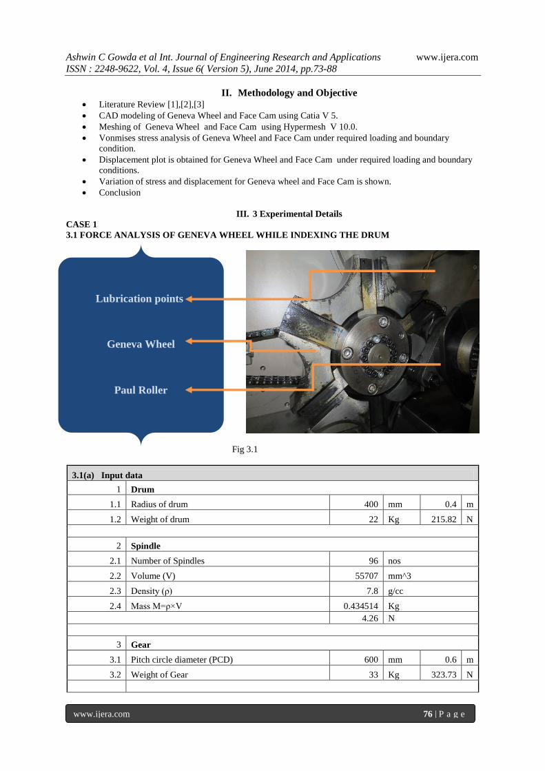
3.1 FORCE ANALYSIS OF GENEVA WHEEL WHILE INDEXING THE DRUM
Fig 3.1
3.1(a) Input data
1 Drum
1.1 Radius of drum 400 mm 0.4 m
1.2 Weight of drum 22 Kg 215.82 N
2 Spindle
2.1 Number of Spindles 96 nos
2.2 Volume (V) 55707 mm^3
2.3 Density (ρ) 7.8 g/cc
2.4 Mass M=ρ×V 0.434514 Kg
4.26 N
3 Gear
3.1 Pitch circle diameter (PCD) 600 mm 0.6 m
3.2 Weight of Gear 33 Kg 323.73 N
Lubrication points
Geneva Wheel
Paul Roller

Ashwin C Gowda et al Int. Journal of Engineering Research and Applications www.ijera.com
ISSN : 2248-9622, Vol. 4, Issue 6( Version 5), June 2014, pp.73-88
www.ijera.com 77 | P a g e
4 Geneva Wheel
4.1 Radius 160 mm
4.2 Angular displacement 60 degree
1.04 Radians
5 Clutch
5.1 Torque ( T' ) 11 Nm
D Moment of Inertia I=1/2× M×R^2
I = I1 + I2+ I3 + I4
(i) M I of Drum I1=(1/2×215.82×0.4^2) 17.26 Nm^2
(ii) M I of Spindle I2=(1/2×4.26×0.4^2)×96 32.71 Nm^2
(iii) M I of Gear I3=(1/2×323.73×0.3^2) 14.56 Nm^2
(iv) M I of Geneva Wheel I4=(1/2×215.82×0.4^2) 17.26 Nm^2
Total MI 81.79 Nm^2
E Angular Acceleration α=(2×s)/t^2
(i) Initial velocity (u) 0 m/s
(ii) Cycle time (t') 1.1 sec
(iii) No of stations (n) in geneva wheel 6 nos
(iv) Total time t=2t'/n=2×1.1/6 0.3666 sec
(v) Angular displacement (s) of drum 0.1308 Radians
(vi) Gear ratio 1:08
Angular Acceleration α=(2×0.1308)/0.3666^2 1.946 Rad/sec^2
F Total Torque Required T=( I × α ) + T'
(i) Torque of Entire System T=I×α =100.48×1.946 159.16334 Nm
(ii) Torque of Starting Clutch 11 Nm
Total Torque 170.16334 Nm
G Tangential Force Required to run the Geneva Wheel considering min and
max positions
F = T / R
(i) Min position ( R ) 81 mm 0.081 m
(ii) Total travel 60 degree
(iii) Max position ( R' ) R'=81+60 141 mm 0.141 m
Tangential Force at min position Fᵗ1=T/R
=170.2/0.081 2101.27 N

Ashwin C Gowda et al Int. Journal of Engineering Research and Applications www.ijera.com
ISSN : 2248-9622, Vol. 4, Issue 6( Version 5), June 2014, pp.73-88
www.ijera.com 78 | P a g e
Tangential Force at max position Fᵗ2=T/R'
=170.2/0.141 1207.09 N
Table 3.1(a)
CASE 2
3.2 FORCE ANALYSIS OF FACE CAM WHILE INDEXING WORK PIECE CARRIER (WPC)
Fig 3.2
3.2(a) INPUT DATA
1 WPC
1.1 No of WPC (n) 5 nos
1.2 Wt of each WPC (w) 3.5 Kg cad value
1.3 Sliding Friction ( µs) Al to steel 0.6 from data hand book table 14.1
2 Components
2.1 No of Components (n')
50
nos/WPC ×5 250 nos
2.2 Weight of the component (w') 0.02 Kg
3 Indexing Shaft
3.1 Length ( l ) 1190 mm 1.19 m
3.2 Diameter ( d ) 43 mm 0.043 m
3.3 Rolling Friction ( µr) steel to steel 0.08
from data hand book table
14.2
4 Spring
4.1 Type of Spring Helical/ Extension
4.2 No of Springs (n") 4 nos
4.3 Mean Diameter ( D ) 20 mm
Swing Arm
Face Cam
Shaft
Ashwin C Gowda et al Int. Journal of Engineering Research and Applications www.ijera.com
ISSN : 2248-9622, Vol. 4, Issue 6( Version 5), June 2014, pp.73-88
www.ijera.com 79 | P a g e
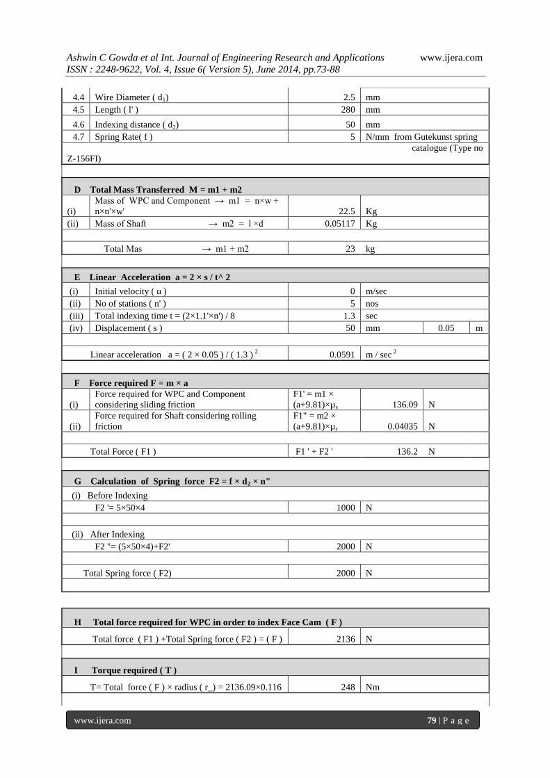
4.4 Wire Diameter ( d1) 2.5 mm
4.5 Length ( l' ) 280 mm
4.6 Indexing distance ( d2) 50 mm
4.7 Spring Rate( f ) 5 N/mm from Gutekunst spring
catalogue (Type no
Z-156FI)
D Total Mass Transferred M = m1 + m2
(i)
Mass of WPC and Component → m1 = n×w +
n×n'×w' 22.5 Kg
(ii) Mass of Shaft → m2 = l ×d 0.05117 Kg
Total Mas → m1 + m2 23 kg
E Linear Acceleration a = 2 × s / t^ 2
(i) Initial velocity ( u ) 0 m/sec
(ii) No of stations ( n' ) 5 nos
(iii) Total indexing time t = (2×1.1'×n') / 8 1.3 sec
(iv) Displacement ( s ) 50 mm 0.05 m
Linear acceleration a = ( 2 × 0.05 ) / ( 1.3 ) 2 0.0591 m / sec
2
F Force required F = m × a
(i)
Force required for WPC and Component
considering sliding friction
F1' = m1 ×
(a+9.81)×µs 136.09 N
(ii)
Force required for Shaft considering rolling
friction
F1" = m2 ×
(a+9.81)×µr 0.04035 N
Total Force ( F1 ) F1 ' + F2 ' 136.2 N
G Calculation of Spring force F2 = f × d2 × n"
(i) Before Indexing
F2 '= 5×50×4 1000 N
(ii) After Indexing
F2 "= (5×50×4)+F2' 2000 N
Total Spring force ( F2) 2000 N
H Total force required for WPC in order to index Face Cam ( F )
Total force ( F1 ) +Total Spring force ( F2 ) = ( F ) 2136 N
I Torque required ( T )
T= Total force ( F ) × radius ( r_) = 2136.09×0.116 248 Nm

Ashwin C Gowda et al Int. Journal of Engineering Research and Applications www.ijera.com
ISSN : 2248-9622, Vol. 4, Issue 6( Version 5), June 2014, pp.73-88
www.ijera.com 80 | P a g e
Table 3.2(a)
IV. Results and Discussions 4.1 Material Properties considered for the analysis[3]
Material - Case hardened Steel
Density - 7.85 × 10⁻⁹
Tonnes / mm3
Youngs modulus - 2.1 × 10 5 N/ mm
2
Poissons ratio - 0.3
Yield strength - 250 N/mm2
4.2 Geometry received for Analysis
Fig 4.2 (a) 3 D Part Model of Geneva Wheel
J Tangential Force at Indexing side ( Ft 1 )
Ft 1 = F / cos Ɵ = 2136.09 / cos 37 ̊ 2674.6 N
K Tangential Force at driving side (cam side) ( Ft 2 )
Ft 2 = T / R = 248 / 0.145 1708.8 N
Angle at which the Ft 2 is acting Ɵ = 37 ̊
L Effective Force acting on the Cam ( F ')
F' = Ft 2 / cos Ɵ = 1708.8 / cos 37 ̊ 2139.64 N
Ashwin C Gowda et al Int. Journal of Engineering Research and Applications www.ijera.com
ISSN : 2248-9622, Vol. 4, Issue 6( Version 5), June 2014, pp.73-88
www.ijera.com 81 | P a g e
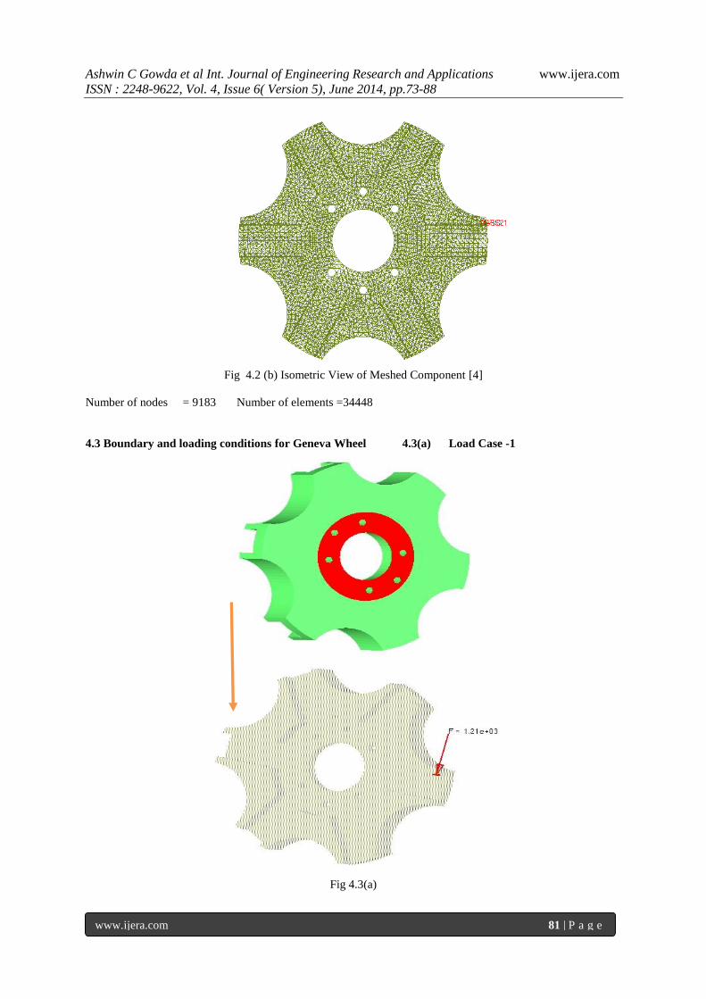
Fig 4.2 (b) Isometric View of Meshed Component [4]
Number of nodes = 9183 Number of elements =34448
4.3 Boundary and loading conditions for Geneva Wheel 4.3(a) Load Case -1
Fig 4.3(a)
Ashwin C Gowda et al Int. Journal of Engineering Research and Applications www.ijera.com
ISSN : 2248-9622, Vol. 4, Issue 6( Version 5), June 2014, pp.73-88
www.ijera.com 82 | P a g e
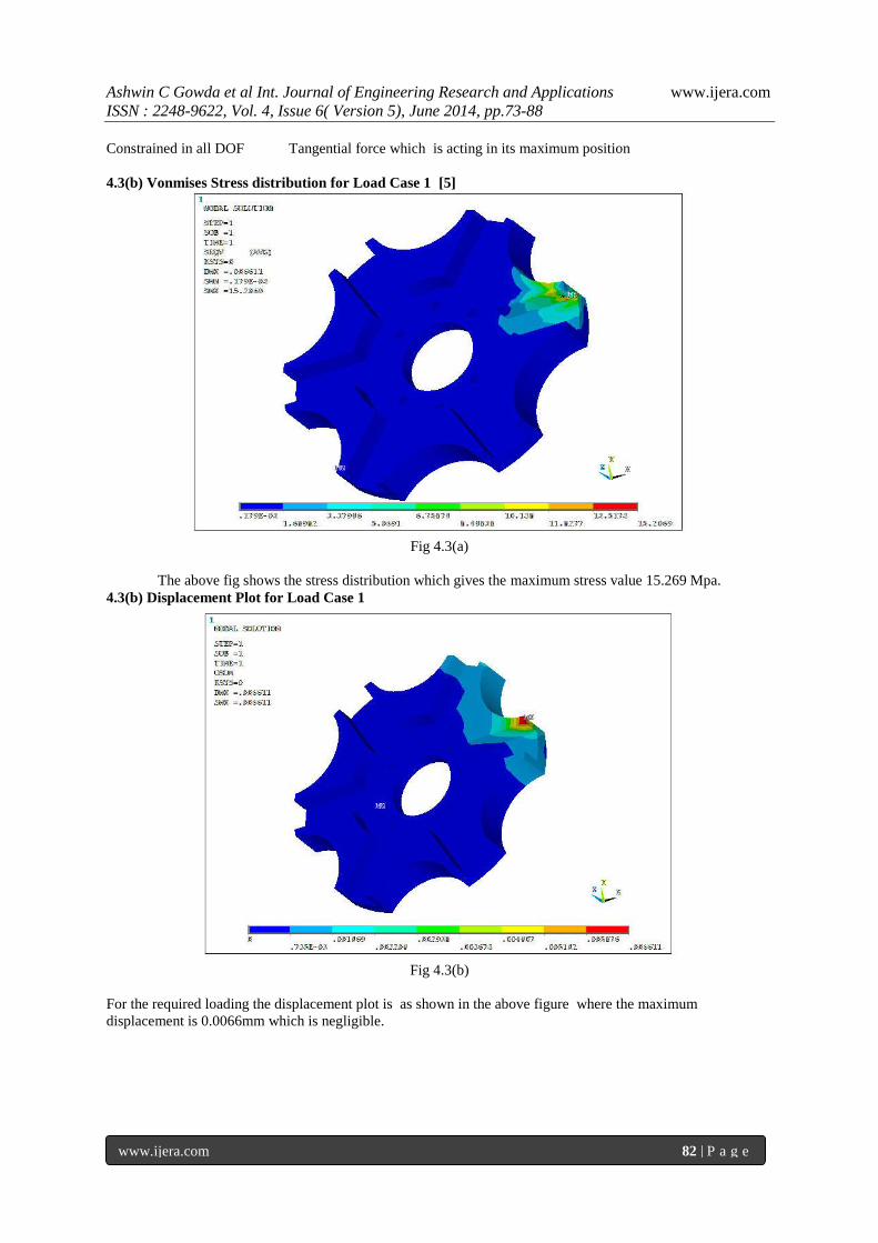
Constrained in all DOF Tangential force which is acting in its maximum position
4.3(b) Vonmises Stress distribution for Load Case 1 [5]
Fig 4.3(a)
The above fig shows the stress distribution which gives the maximum stress value 15.269 Mpa.
4.3(b) Displacement Plot for Load Case 1
Fig 4.3(b)
For the required loading the displacement plot is as shown in the above figure where the maximum
displacement is 0.0066mm which is negligible.

Ashwin C Gowda et al Int. Journal of Engineering Research and Applications www.ijera.com
ISSN : 2248-9622, Vol. 4, Issue 6( Version 5), June 2014, pp.73-88
www.ijera.com 83 | P a g e
4.3( c) Variation of Stress and Displacement for the force acting in maximum position
Fig 4.3(c)
The variation of displacement with the increase in stress for the force of 1.21 e+3
acting on the maximum
position of the geneva wheel is as shown in the above fig.
4.3(d) Load Case 2
Fig 4.3(d)
Tangential force which is acting in its minimum position
4.3(e) Von Mises stress distribution for Load Case 2
Fig 4.3(e)

Ashwin C Gowda et al Int. Journal of Engineering Research and Applications www.ijera.com
ISSN : 2248-9622, Vol. 4, Issue 6( Version 5), June 2014, pp.73-88
www.ijera.com 84 | P a g e
The above fig 5.4(a) shows the stress distribution which gives the maximum stress 16.636Mpa.
4.3(f) Displacement Plot for Load Case 2
Fig 4.3(f)
The Displacement plot is as shown in the above fig where the maximum displacement is 0.0035mm.
4.3(g) Variation of Stress and Displacement for the force acting in minimum position
Fig 4.3(g)
The variation of displacement with the increase in stress for the force of 1.21 e+3
acting on the minimum
position of the geneva wheel is as shown in the above fig.

Ashwin C Gowda et al Int. Journal of Engineering Research and Applications www.ijera.com
ISSN : 2248-9622, Vol. 4, Issue 6( Version 5), June 2014, pp.73-88
www.ijera.com 85 | P a g e
4.4 Geometry received for Analysis
Fig 4.4 (a) 3D Part Model of Face Cam
Fig 4.4( b) Isometric view of the Meshed component
Number of nodes = 6551 Number of elements =24564

Ashwin C Gowda et al Int. Journal of Engineering Research and Applications www.ijera.com
ISSN : 2248-9622, Vol. 4, Issue 6( Version 5), June 2014, pp.73-88
www.ijera.com 86 | P a g e
4.5 Boundary and Loading Conditions for Face Cam
Constrained in all DOF Tangential force is applied in horizontal direction.
Fig 4.5
4.5(a) Vonmises Stress distribution
Fig 4.5(a)
The above fig shows the stress distribution which gives the maximum stress 14.54Mpa.

Ashwin C Gowda et al Int. Journal of Engineering Research and Applications www.ijera.com
ISSN : 2248-9622, Vol. 4, Issue 6( Version 5), June 2014, pp.73-88
www.ijera.com 87 | P a g e
4.5 (b) Displacement Plot
Fig 4.5(b)
The Displacement plot is as shown in the above fig where the maximum displacement is 0.0023mm.
4.5(c) Variation of Stress and Displacement for the force acting on the Face Cam
Fig4.5(c)
The variation of displacement with the increase in stress for the force of 2.17 e+3
acting on the Face Cam is as
shown in the above fig.
V. Conclusion FEA has enabled a complete view of the stress
distribution around the Geneva wheel and Face
Cam.
Deflection is small for the force acting on
maximum and minimum position of Geneva
Wheel.
Similarly deflection is small for the force acting
on the Face Cam.
The Variation of displacement with the stress for
the maximum and minimum condition of the
Geneva wheel and also Face Cam has increased
non linearly.

Ashwin C Gowda et al Int. Journal of Engineering Research and Applications www.ijera.com
ISSN : 2248-9622, Vol. 4, Issue 6( Version 5), June 2014, pp.73-88
www.ijera.com 88 | P a g e
The factor of safety for the conditions of Geneva
Wheel and Face Cam is found to be more than
10.Hence the probability of failure is very
less.Thus the design is very much safe.
Reference [1] Varadarajan Vidya Department of Electrical
Engineering Department of Mechanical
Engineering Palani Kumaresan University
of California, Berkeley University of
California, Berkeley
[2] Elearning.vtu.ac.in/P6/enotes/ME44/Unit 6-
AP
[3] E.J. Pavlina and C.J. Van Tyne, "Correlation
of Yield strength and Tensile strength
hardness of steels” Journal of Materials
Engineering and Performance, 17:6
(December 2008)
[4] J.-D. Boissonnat and S. Oudot. Provably good
sampling and meshing of surfaces. Graphical
Models, 67:405{451, 2005. [23, 28]
[5] Ansys Release 10.0 Documentation ANSYS
Inc 2005.