for smooth motor control and energy savings low …
TRANSCRIPT

— FOR SMOOTH MOTOR CONTROL AND ENERGY SAVINGS
Low voltage AC drives and softstartersProduct guide

— AC drives and softstarters. For smooth motor control and energy savings.

3
— Table of contents
4 Smooth motor control and energy savings
6 Choosing the right drive for your application
7 Horsepower comparison8 Drive selection table10 ACS55, micro drives11 ACS150, micro drives13 ACS355, machinery drives14 ACS380, machinery drives15 ACS310, general purpose drives16 ACS580, general purpose drives17 ACS880, industrial drives18 DCS800, DC drives19 Softstarters23 Introducing the most extensive
drives and softstarters portfolio in the world
25 A lifetime of peak performance26 Services to match your needs27 Drives and softstarters service

4 PRO D U C T G U I D E
—Smooth motor control and energy savings
What is an AC drive?An AC drive is an electronic device that is used to adjust the rotating speed and torque of a standard, electric AC motor. The electric motor, in turn, drives a load such as a fan, pump or conveyor.
AC drives are also referred to as frequency converters, variable frequency drives (VFD), variable speed drives (VSD), adjustable frequency drives (AFD), adjustable speed drives (ASD) or inverters.
What is a softstarter?Softstarter is a full-speed starter that accelerates, decelerates and protects three phase motors. The softstarter controls the voltage
applied to the motor by using thyristors which gives it control over current, torque and acceleration. The softstarter s parameters can be configured to match the application s requirements, so that the required current and torque are optimized.
ABB - global market and technology leader in AC drivesABB (www.abb.com) is a leader in power and automation technologies that enable utility and industry customers to improve their performance while lowering environmental impact. ABB is the world’s largest drives manufacturer. The ABB Group of companies operates in around 100 countries and employs more than 140,000 people.
— Electric motors consume about 65% of all electricity used throughout industry. Yet, less than 10% of those motors are fitted with a variable speed drive or a softstarter.
Softstarters are ideal choice when an application requires speed and torque control only during startup. The softstarters prevent large inrush currents from being drawn while starting the motor by smoothly ramping up the supply voltage. The smooth ramp up prolongs the life
time of the motors because less current means also less heat in the motors. AC drives, on the other hand, are good choice when speed control only during a startup is not enough, big energy savings are a must, custom motor control is required, or more functionalities are needed.

PRO D U C T G U I D E 5
—Improve your processes with softstarters and AC drives
Increased life timeReduced starting current decreases the electrical stress on the motor and network. Smooth ramp up to full speed also reduces mechanical wear on the equipment prolonging its life time.
Increased productivityUsing softstarters and drives increases the productivity of the applications by reducing the number of unintended stops caused by excessive heating of the motor or sudden breakdowns of mechanical equipment due to high mechanical stress.
Reduced need for maintenanceBeing able to apply a softer starting moment and vary the speed and torque of an electric motor means there is less wear and tear on the motor and the driven machine.
—Further optimize your processes with AC drives
Substantial energy savingsRather than having an electric motor running continuously at full speed, an electric drive allows the user to slow down or speed up the motor depending on the demand.
Optimal process controlAn electric drive enables the process to achieve the right speed and torque while maintaining its accuracy. This contributes to more consistent quality and throughput of the end product.
Efficient system upgradeAn AC drive allows the removal of some valves, gears and belts. It also ensures network dimensioning based on a lower starting current.
Identify the application
1 Is it a full speed application, or a variable speed application?
2 Is speed and torque control during start-ups enough, or does the speed and torque need to be controlled also during run cycles?
3 Is smooth start-up enough, or are energy savings sought?
Choose a softstarter Choose an AC drive
Softstarters offer you a complete range of products for full speed applications. See the softstarter product pages, starting on page 20, to select the softstarter for your needs.
Variable speed drives offer you a right product for variable speed applications. See the drive selection tool on page 8 to select the drive to match your needs.
Application examples:Softstarters: pumps, compressors, fans, conveyors, bow thrusters, crushers etc.Variable speed drives: conveyors, fans, mixers, grinders, elevators, cranes, compressors, etc.
Choosing between a drive and a softstarter
—ABB drives and softstarters common features• Easy to select
You can be sure to find a right product for your application from a wide selection of ABB softstarters and AC drives.
• Easy to purchaseABB softstarters and drives are available from ABB and selected ABB partners. Please contact ABB for more details.
• Easy to installThe softstarters and drives are simple to install, featuring a variety of mounting options from wall-mounted to cabinet mounted.
• Easy to operateOnce installed and commissioned, the soft-starters and drives are incredibly easy to operate. The user interface allows instant adjustments to speed or other more advanced parameters.

6 PRO D U C T G U I D E
Step Process Action
1 Identify the applicationIdentify the type of application and the likely demands of the drive. Continue to step 2.
2 Gather the load data: system inertia, required acceleration and deceleration rates, minimum and maximum speeds, overload requirements, etc.This information can often be determined by the performance of the existing motor. Continue to step 3.
3 Gather the motor data: rated torque, kW, volts, insulation class, speed, etc.Whether an existing motor or a new motor is being used, the motor information is critical to choosing a drive. Continue to step 4.
4 Choose a driveMatch the data gathered in Steps 1 to 3 against the table of drive features on page 8-9. Select a drive that meets the motor requirements and has all the software features needed for the application. Continue to step 5.
5 Is the drive offered in the correct hp rating?The drive you choose must be able to supply the necessary current to the motor to produce the torque required. This includes normal and overload conditions. Select current from the tables on pages 7, depending on drive type selected.
If yes, continue to step 6. If no, go to step 4.
6 Is the drive offered in the correct enclosure and environmental ratings?The drive you choose must be available in an enclosure style that will withstand the application’s environment. It also must produce the required current at the application’s altitude and ambient temperature.
If yes, continue to step 7. If no, go to step 4.
7 Does this drive have the features needed to meet the application’s demands?The drive you choose must have a feature set that matches the application. It also must have sufficient hardware (inputs and outputs, feedback, communications, etc.) to perform the application.
If yes, continue to step 8. If no, go to step 4.
8 Does this drive have the motor control performance to meet the application’s demands?The drive you choose must be able to produce the needed torque at the necessary speeds. It must also be able to control speed and torque depending on the application requirements.
If yes, continue to step 9. If no, go to step 4.
9 Congratulations!The ABB AC drive you have chosen has the features and performance needed for a successful application.
—Choosing the right drive for your application
Applications
Micro drives Machinery drive General purpose drives Industrial drives
ACS55 ACS150 ACS255 ACS355 ACS380 ACS310 ACS580 ACS880 DCS880
General purpose/broad distribution
l l
Food & beverage l l l
Irrigation l l l l
MCC l
Compressor l l
Conveyor l l l l
Fan l l l l l
Mixer l l
Pump l l l l
Integrated / machinery l l l l l l l
Oil & gas l l
Metals & mining l l
Rubber & plastic l
Electric Power Generation l l
Centrifuge l
Extruder l l
Hoist crane l
Overhead / gantry crane l l l
Punch press l
Winder l

PRO D U C T G U I D E 7
ACS55
1-phase, 120V
1-phase, 240V
ACS150
1-phase, 240V
3-phase, 240V
3-phase, 480V
ACS255
1-phase, 120V
1-phase, 240V
3-phase, 240V
3-phase, 480V
3-phase, 600V
ACS355
1-phase, 240V
3-phase, 240V
3-phase, 480V
ACS380
1-phase, 240V
3-phase, 240V
3-phase, 480V
ACS310
1-phase, 240V
3-phase, 240V
3-phase, 480V
ACS580
3-phase, 240V
3-phase, 480V
3-phase, 600V
ACS880
3-phase, 240V
3-phase, 480V
3-phase, 600V
DCS800
3-phase, 500V
3-phase, 600V
3-phase, 700V
0.25 0.5 1 3 5 7.5 10 15 20 25 30 40 50 60 75 100 150 200 250 550 750 1000 1500 2000 2500 3000 3250
—Horsepower comparison
0.25-0.5
0.25 3
0.5 3
0.5 3
0.5 5
0.5-1.5
0.5 5
0.5 15
0.5 30
1 20
0.5 3
0.5 15
0.5 30
0.5 3
0.5 15
30
0.5 5
0.5 15
0.5 30
1 100
1 700
2 250
0.75 100
0.75 1950
5 3300
5 3000
200 3250
500 4000

8 PRO D U C T G U I D E
—Drive selection tableSpecification ACS55 ACS150 ACS255 ACS355 ACS380 Specification ACS310 ACS580 ACS880 DCS800
Voltage and power ranges 1-phase, 100 to 120 V: 0.25 to 0.5 hp
(0.18 to 0.37 kW)
1-phase, 200 to 240 V: 0.5 to 3 hp
(0.37 to 2.2 kW)
1-phase, 110 to 120 V: 0.5 to 1.5 hp
(0.37 to 1.1 kW)
1-phase, 200 to 240 V: 0.5 to 3 hp
(0.37 to 4 kW)
1-phase, 200 to 240 V:0.5 to 3 hp
(0.37 to 2.2 kW)
Voltage and power ranges 1-phase, 200 to 240 V: 0.5 to 5 hp
(0.37 to 4 kW)
3-phase, 208 to 240V:1 to 100 hp
(0.75 to 75 kW)
3-phase, 208 to 240V: 0.75 to 100 hp
(0.75 to 75 kW)
3-phase, 230 to 525 V: 5 to 3000 hp
(4 to 2250 kW)
1-phase, 200 to 240 V: 0.25 to 3 hp
(0.18 to 2.2 kW)
3-phase, 200 to 240 V: 0.5 to 3 hp
(0.37 to 2.2 kW)
1-phase, 200 to 240 V: 0.5 to 5 hp
(0.37 to 4 kW)
3-phase, 200 to 240 V:0.5 to 15 hp
(0.37 to 11 kW)
3-phase, 200 to 240 V:0.5 to 15 hp
(0.37 to 11 kW)
3-phase, 200 to 240 V:0.5 to 15 hp
(0.37 to 11 kW)
3-phase, 380 to 480 V:1 to 700 hp
(0.75 to 522 kW)
3-phase, 380 to 500 V: 0.75 to 1950 hp
(0.75 to 1500 kW)
3-phase, 600 V: 200 to 3250 hp
(150 to 1700 kW)
3-phase, 380 to 480 V: 0.5 to 5 hp
(0.37 to 4 kW)
3-phase, 200 to 240 V:0.5 to 15 hp
(0.37 to 11 kW)
3-phase, 380 to 480 V: 0.5 to 30 hp
(0.37 to 22 kW)
3-phase, 380 to 480 V:0.5 to 30 hp
(0.37 to 22 kW)
3-phase, 380 to 480 V:0.5 to 30 hp
(0.37 to 22 kW)
3-phase, 500 to 600 V:2 to 250 hp
(1.5 to 180 kW)
3-phase, 525 to 690V: 5 to 3300 hp
(4 to 3200 kW)
3-phase, 700 V: 500 to 4000 hp
(400 to 3000 kW)
3-phase, 380 to 480 V:0.5 to 30 hp
(0.37 to 22 kW)
higher upon request
3-phase, 500 to 600 V: 1 to 15 hp (0.75 to 11 kW)1)
1 to 20 hp (0.75 to 15 kW)Protection classes
UL type 0/IP20 l l l l l
Protection classes
UL type 0/IP20 l – l lUL type 1/IP21 – – – O – UL type 1/IP21 O l l –UL Type 12/IP54/IP55 – – – – – UL Type 12/IP54/IP55 – l l –UL Type 4X/IP66/IP67 – – l l1) – UL Type 4X/IP66/IP67 – – – –UL type 3R – – – – – UL type 3R – O 13) – –
Mounting arrangements
Optimal for cabinet mounting l l l8) l • Mounting arrangements
Optimal for cabinet mounting l l Requires flange
mount kitl Requires flange
mount kit l
Optimal for wall mounting – O l1) O – Optimal for wall mounting O l l –
Programming Parameter programming l l l l •Programming
Parameter programming l l l lSequence programming – – – l l 13) Sequence programming – l – –
Human-Machineinterface
Basic control panel – – – O – Human-Machineinterface
Basic control panel O – – –Assistant control panel – – – O /l1) – Assistant control panel O l O lBluetooth enabled panel – – – – O Bluetooth enabled panel – O l –Integrated control panel l l l – l Integrated control panel – – – –
Motor Control Scalar (V/Hz) selectable for linear (CT) or square
function (VT)
Scalar (V/Hz) selectable for linear (CT) or square
function (VT)
Open loop vector, Scalar (V/Hz), enhanced
V/Hz or open loop vector
Open loop vector, Scalar (V/Hz) and Closed
loop control
Open loop vector, Scalar (V/Hz) and Closed loop control -
AC induction and PMAC motors
Motor Control
Scalar (V/Hz) - Linear (CT), squared (VT), or
user defined curve
Open Loop Vector, Scalar (V/Hz)
Direct Torque Control (DTC), Scalar (V/Hz)
–
Ambient temperature -4 to 104˚F (-20 to 40˚C), 50 ˚C (122˚F)
with 15% derate, 55˚C (131 C)
with 25% derateNo frost allowed.
14 to 104˚F (-10 to +40˚C), 122˚F (+50˚C) with derating
No frost allowed.
UL Type 0: 14 to 104˚F (-10 to 40˚C),122˚F (50˚C) with derate
UL type 4X:14 to 104˚F (-10 to 40˚C),
No frost allowed.
14 to 104˚F (-10 to 40˚C), 122˚F (50˚C)
with deratingNo frost allowed.
14 to 122˚F (-10 to 50˚C), Up to 140˚F (60˚C)
with derating No frost allowed.
Ambient temperature 14 to 104˚F (-10 to +40˚C),up to 50˚C with
10% derateNo frost allowed.
5 to 122˚F (-15 to +50˚C)From 104 to 122˚F
(+40 to +50˚C) with derating.
No frost allowed.
5 to 131 F (-15 to +55˚C)From 104 to 131 F
(40 to 55˚C) with derating.
No frost allowed.
32 to 104˚F (0 to 40˚C) From 104 to 131 F
(40 to 55˚C) with derating.
No frost allowed.
Inputs and outputs
Digital inputs/outputs 3/0 5/0 4/0 5/1 4/2 5)
Inputs and outputs
Digital inputs/outputs 5/1 6/0 6/8 11,12) 8/7Relay outputs 1 1 1 (+1 as option) 1 (+3 as option) 1 (+4 as option) Relay outputs 1 (+3 as option) 3 + (3 as option) 3 11) 1Analog inputs/outputs 1/0 2/1 2/1 2/1 2 Analog inputs/outputs 2/1 2 /2 2/2 11) 4/2Encoder feedback – – – O l Speed feedback – – O l
Supported fieldbus protocols
Modbus RTU – – l O l
Supported fieldbus protocols
Modbus RTU l l l/O OProfibus DP – – – O l Profibus DP – O O ODeviceNetTM – – – O – DeviceNetTM – O O OControlNet – – – O – ControlNet – O O OCANopen® – – – O l CANopen® – O O OEthernet (Modbus/TCP) – – – O l Ethernet (Modbus/TCP) – O O OEthernet (EtherNet/IPTM) – – – O l Ethernet (EtherNet/IPTM) – O O OEthernet (EtherCAT®) – – – O l Ethernet (EtherCAT®) – O O OEthernet (PROFINET IO) – – – O l Ethernet (PROFINET IO) – O O OEthernet (PowerLink) – – – – l Ethernet (PowerLink) – O O O
EMC compliance(EN 61800-3)
C3, industrial use O l O l OEMC compliance(EN 61800-3)
C3, industrial use l l O lC2, commercial use (installation by EMC experts) O O O O O C2, commercial use
(installation by EMC experts) l l O O
C1, commercial use O(conductive emissions) O (conductive emissions) O O (conductive emissions) O C1, commercial use O (conductive emissions) O(conductive emissions) – –Input reactors – O O O O Input reactors O l l(built-in) Required; supplied by othersOutput reactors – O O O O Output reactors O O O(cabinets) –
Brake chopper – l Sizes 2 & 3 only l l Brake chopper – R1-R3 Frames l/O6) Not applicable
Suggested maximum motor cable length 98.5 to 164 ft (30 to 50 m)
98.5 to 196.9 ft (30 to 60 m)
328 ft (100 m)
98.5 to 196,9 ft (30 to 60 m)
98.5 to 196.9 ft (30 to 60 m)
Suggested maximum motor cable length 98.5 to 196.9 ft (30 to 60 m) 300m 5000 ft / 1000 ft 6)
(150m / 300m) 6) Not applicable
Switching frequency up to 16 kHz up to 16 kHz up to 32 kHz up to 16 kHz up to 12 kHz Switching frequency up to 16 kHz 2, 4, 8, 12 kHz 2.7 kHz (typical) Not applicableOutput frequency 0-130Hz (0/250Hz) 10) 0 to 500 Hz 0 to 500 Hz 0 to 599 Hz 0 to 599 Hz Output frequency 0 to 500 Hz 0 to 500Hz 0 to 500 Hz Not applicableOverload capacity 150% for 60 s,
180% for 2s at start150% for 60 s,
180% for 2 s150% for 60 s,
175% for 2 s150% for 60 s,
180% for 2 s150% for 60 s,
180% for 2 sOverload capacity 110% for 60 s,
180% for 2 s110% for 1 minute every 10
minutes110% for 60s,150% for 60s
150% for 60 s, 150% for 30 s, 110% for 60 s
Number of preset speeds 1 10) 3 4 7 7 Number of preset speeds 7 7 7 4
PC tools Drive commissioning tool O – – O lPC tools
Drive commissioning tool O O O lDrive offline prog tool – O – O l Drive offline prog tool O O – –Drive dimensioning tool – – – – l Drive dimensioning tool – O O O
Approvals UL, cUL, CE, RMS, C-Tick, EAC l l l l l Approvals UL, cUL, CE, RMS, C-Tick, EAC l l l lRoHS compliance l l l l l RoHS compliance l l l l
l Standard O Option — Not Available
1) IP66 product variants 2) up to R2 as standard 3) G1/G2 frames IP00 4) Application Programming 5) DO are DIO and can be used as DI
6) Frame dependent 7) CC, PC, and PD product variants 8) IP20 variant9) IP54 variant
10) Greater range when programmed with DriveConfig software11) I/O can be expanded with optional modules12) Eight digital outputs can be configured to be DI or DO13) ACS580-0P only

PRO D U C T G U I D E 9
Specification ACS55 ACS150 ACS255 ACS355 ACS380 Specification ACS310 ACS580 ACS880 DCS800
Voltage and power ranges 1-phase, 100 to 120 V: 0.25 to 0.5 hp
(0.18 to 0.37 kW)
1-phase, 200 to 240 V: 0.5 to 3 hp
(0.37 to 2.2 kW)
1-phase, 110 to 120 V: 0.5 to 1.5 hp
(0.37 to 1.1 kW)
1-phase, 200 to 240 V: 0.5 to 3 hp
(0.37 to 4 kW)
1-phase, 200 to 240 V:0.5 to 3 hp
(0.37 to 2.2 kW)
Voltage and power ranges 1-phase, 200 to 240 V: 0.5 to 5 hp
(0.37 to 4 kW)
3-phase, 208 to 240V:1 to 100 hp
(0.75 to 75 kW)
3-phase, 208 to 240V: 0.75 to 100 hp
(0.75 to 75 kW)
3-phase, 230 to 525 V: 5 to 3000 hp
(4 to 2250 kW)
1-phase, 200 to 240 V: 0.25 to 3 hp
(0.18 to 2.2 kW)
3-phase, 200 to 240 V: 0.5 to 3 hp
(0.37 to 2.2 kW)
1-phase, 200 to 240 V: 0.5 to 5 hp
(0.37 to 4 kW)
3-phase, 200 to 240 V:0.5 to 15 hp
(0.37 to 11 kW)
3-phase, 200 to 240 V:0.5 to 15 hp
(0.37 to 11 kW)
3-phase, 200 to 240 V:0.5 to 15 hp
(0.37 to 11 kW)
3-phase, 380 to 480 V:1 to 700 hp
(0.75 to 522 kW)
3-phase, 380 to 500 V: 0.75 to 1950 hp
(0.75 to 1500 kW)
3-phase, 600 V: 200 to 3250 hp
(150 to 1700 kW)
3-phase, 380 to 480 V: 0.5 to 5 hp
(0.37 to 4 kW)
3-phase, 200 to 240 V:0.5 to 15 hp
(0.37 to 11 kW)
3-phase, 380 to 480 V: 0.5 to 30 hp
(0.37 to 22 kW)
3-phase, 380 to 480 V:0.5 to 30 hp
(0.37 to 22 kW)
3-phase, 380 to 480 V:0.5 to 30 hp
(0.37 to 22 kW)
3-phase, 500 to 600 V:2 to 250 hp
(1.5 to 180 kW)
3-phase, 525 to 690V: 5 to 3300 hp
(4 to 3200 kW)
3-phase, 700 V: 500 to 4000 hp
(400 to 3000 kW)
3-phase, 380 to 480 V:0.5 to 30 hp
(0.37 to 22 kW)
higher upon request
3-phase, 500 to 600 V: 1 to 15 hp (0.75 to 11 kW)1)
1 to 20 hp (0.75 to 15 kW)Protection classes
UL type 0/IP20 l l l l l
Protection classes
UL type 0/IP20 l – l lUL type 1/IP21 – – – O – UL type 1/IP21 O l l –UL Type 12/IP54/IP55 – – – – – UL Type 12/IP54/IP55 – l l –UL Type 4X/IP66/IP67 – – l l1) – UL Type 4X/IP66/IP67 – – – –UL type 3R – – – – – UL type 3R – O 13) – –
Mounting arrangements
Optimal for cabinet mounting l l l8) l • Mounting arrangements
Optimal for cabinet mounting l l Requires flange
mount kitl Requires flange
mount kit l
Optimal for wall mounting – O l1) O – Optimal for wall mounting O l l –
Programming Parameter programming l l l l •Programming
Parameter programming l l l lSequence programming – – – l l 13) Sequence programming – l – –
Human-Machineinterface
Basic control panel – – – O – Human-Machineinterface
Basic control panel O – – –Assistant control panel – – – O /l1) – Assistant control panel O l O lBluetooth enabled panel – – – – O Bluetooth enabled panel – O l –Integrated control panel l l l – l Integrated control panel – – – –
Motor Control Scalar (V/Hz) selectable for linear (CT) or square
function (VT)
Scalar (V/Hz) selectable for linear (CT) or square
function (VT)
Open loop vector, Scalar (V/Hz), enhanced
V/Hz or open loop vector
Open loop vector, Scalar (V/Hz) and Closed
loop control
Open loop vector, Scalar (V/Hz) and Closed loop control -
AC induction and PMAC motors
Motor Control
Scalar (V/Hz) - Linear (CT), squared (VT), or
user defined curve
Open Loop Vector, Scalar (V/Hz)
Direct Torque Control (DTC), Scalar (V/Hz)
–
Ambient temperature -4 to 104˚F (-20 to 40˚C), 50 ˚C (122˚F)
with 15% derate, 55˚C (131 C)
with 25% derateNo frost allowed.
14 to 104˚F (-10 to +40˚C), 122˚F (+50˚C) with derating
No frost allowed.
UL Type 0: 14 to 104˚F (-10 to 40˚C),122˚F (50˚C) with derate
UL type 4X:14 to 104˚F (-10 to 40˚C),
No frost allowed.
14 to 104˚F (-10 to 40˚C), 122˚F (50˚C)
with deratingNo frost allowed.
14 to 122˚F (-10 to 50˚C), Up to 140˚F (60˚C)
with derating No frost allowed.
Ambient temperature 14 to 104˚F (-10 to +40˚C),up to 50˚C with
10% derateNo frost allowed.
5 to 122˚F (-15 to +50˚C)From 104 to 122˚F
(+40 to +50˚C) with derating.
No frost allowed.
5 to 131 F (-15 to +55˚C)From 104 to 131 F
(40 to 55˚C) with derating.
No frost allowed.
32 to 104˚F (0 to 40˚C) From 104 to 131 F
(40 to 55˚C) with derating.
No frost allowed.
Inputs and outputs
Digital inputs/outputs 3/0 5/0 4/0 5/1 4/2 5)
Inputs and outputs
Digital inputs/outputs 5/1 6/0 6/8 11,12) 8/7Relay outputs 1 1 1 (+1 as option) 1 (+3 as option) 1 (+4 as option) Relay outputs 1 (+3 as option) 3 + (3 as option) 3 11) 1Analog inputs/outputs 1/0 2/1 2/1 2/1 2 Analog inputs/outputs 2/1 2 /2 2/2 11) 4/2Encoder feedback – – – O l Speed feedback – – O l
Supported fieldbus protocols
Modbus RTU – – l O l
Supported fieldbus protocols
Modbus RTU l l l/O OProfibus DP – – – O l Profibus DP – O O ODeviceNetTM – – – O – DeviceNetTM – O O OControlNet – – – O – ControlNet – O O OCANopen® – – – O l CANopen® – O O OEthernet (Modbus/TCP) – – – O l Ethernet (Modbus/TCP) – O O OEthernet (EtherNet/IPTM) – – – O l Ethernet (EtherNet/IPTM) – O O OEthernet (EtherCAT®) – – – O l Ethernet (EtherCAT®) – O O OEthernet (PROFINET IO) – – – O l Ethernet (PROFINET IO) – O O OEthernet (PowerLink) – – – – l Ethernet (PowerLink) – O O O
EMC compliance(EN 61800-3)
C3, industrial use O l O l OEMC compliance(EN 61800-3)
C3, industrial use l l O lC2, commercial use (installation by EMC experts) O O O O O C2, commercial use
(installation by EMC experts) l l O O
C1, commercial use O(conductive emissions) O (conductive emissions) O O (conductive emissions) O C1, commercial use O (conductive emissions) O(conductive emissions) – –Input reactors – O O O O Input reactors O l l(built-in) Required; supplied by othersOutput reactors – O O O O Output reactors O O O(cabinets) –
Brake chopper – l Sizes 2 & 3 only l l Brake chopper – R1-R3 Frames l/O6) Not applicable
Suggested maximum motor cable length 98.5 to 164 ft (30 to 50 m)
98.5 to 196.9 ft (30 to 60 m)
328 ft (100 m)
98.5 to 196,9 ft (30 to 60 m)
98.5 to 196.9 ft (30 to 60 m)
Suggested maximum motor cable length 98.5 to 196.9 ft (30 to 60 m) 300m 5000 ft / 1000 ft 6)
(150m / 300m) 6) Not applicable
Switching frequency up to 16 kHz up to 16 kHz up to 32 kHz up to 16 kHz up to 12 kHz Switching frequency up to 16 kHz 2, 4, 8, 12 kHz 2.7 kHz (typical) Not applicableOutput frequency 0-130Hz (0/250Hz) 10) 0 to 500 Hz 0 to 500 Hz 0 to 599 Hz 0 to 599 Hz Output frequency 0 to 500 Hz 0 to 500Hz 0 to 500 Hz Not applicableOverload capacity 150% for 60 s,
180% for 2s at start150% for 60 s,
180% for 2 s150% for 60 s,
175% for 2 s150% for 60 s,
180% for 2 s150% for 60 s,
180% for 2 sOverload capacity 110% for 60 s,
180% for 2 s110% for 1 minute every 10
minutes110% for 60s,150% for 60s
150% for 60 s, 150% for 30 s, 110% for 60 s
Number of preset speeds 1 10) 3 4 7 7 Number of preset speeds 7 7 7 4
PC tools Drive commissioning tool O – – O lPC tools
Drive commissioning tool O O O lDrive offline prog tool – O – O l Drive offline prog tool O O – –Drive dimensioning tool – – – – l Drive dimensioning tool – O O O
Approvals UL, cUL, CE, RMS, C-Tick, EAC l l l l l Approvals UL, cUL, CE, RMS, C-Tick, EAC l l l lRoHS compliance l l l l l RoHS compliance l l l l

10 PRO D U C T G U I D E
—ACS55, micro drives0.25 to 3 hp (0.18 to 2.2 kW)
What is it?The ACS55 drive is a component that can be integrated easily into existing panels, replacing contactors and motor starters. Its compact size is ideal for new installations or whenever speed control of AC induction motors is needed. For users new to drives, its interface with DIP switches and trimmers is exceptionally intuitive.
The ACS55 drive meets the requirements of new drive users, installers, machine builders and panel builders.
Feature Advantage Benefit
Single phase supply Suitable for single phase residential and commercial applications
Avoids cabling and installation costs associated with three-phase supplies
Slim design Fits easily into a variety of cabinet designs Cabinet size can be smaller or greater packing density can be achieved
Flexible installation alternatives
Screw or DIN rail mounting, sideways or side-by-side
One drive type can be used in various designs, saving installation costs and time
High switching frequency Reduced motor noise Does not disturb occupants of buildings
Integrated EMC filter as standard
High electromagnetic compatibility Low EMC emissions in all environments
Easy configuration Quick setup with DIP switches and trimmers Substantial time savings. Minimal expertise needed.
DriveConfig kit PC tool DriveConfig kit PC tool is used to set drive parameters and to upload the parameter set to a drive in seconds, even without a power connection to the drive. The DIP switches and trimmers on the front panel of the drive are disabled after using the DriveConfig kit. This prevents the end users from altering the drive configuration.
Time savings with multiple drives. Drive configuration protected from end user alterations.
For additional technical information, see the ACS55 Technical Catalog (3AUA0000163305) or www.abb.com/drives.

PRO D U C T G U I D E 11
AC S1 5 0, 0 . 3 7 TO 4 K W
—ACS150, micro drives0.25 to 3 hp (0.18 to 2.2 kW)
What is it?The ACS150 drive is a component that is brought together with other components and includes, as standard, all necessary functions and interfaces for typical applications with AC induction motors. This makes the product selection very easy.
The ACS150 drive meets the requirements of new drive users, installers, machine builders and panel builders.
Feature Advantage Benefit
User-friendly LCD control panel
Clear alphanumeric displayEasy setup and use
Time savings
Flexible mounting alternatives
Screw or DIN rail mounting, sideways or side-by-side
One drive type can be used in various designs, saving installation costs and time
Integrated EMC filter High electromagnetic compatibility Low EMC emissions in selected environments
Built-in brake chopper as standard
No need for an external brake chopper Space savings, reduced installation cost
Embedded potentiometer Easy to adjust output frequency Time savings
PID control Simple integration to process control Cost savings as a result of less cabling
FlashDrop tool FlashDrop is a hand held tool that is used to quickly and easily set drive parameters. FlashDrop tool uploads drive parameters directly to unpowered drives. The tool can copy parameters from one drive to another or between a PC and a drive.
Time savings, especially with multiple drives
For additional technical information, see the ACS150 Technical Catalog (3AUA0000085631) or www.abb.com/drives.

12 PRO D U C T G U I D E
—ACS255, micro drives0.5 to 30 hp (0.37 to 22 kW)
What is it?The ACS255 micro drive offers easy to use and compact solutions for general purpose, low power applications, including mixers, pumps, fans, conveyors. All variants include a built-in Modbus RTU serial communication to provide straightforward integration with control and monitoring systems. Available in IP20 and IP66/NEMA4x enclosures.
Feature Benefit Result
User-friendly LCD control panel Clear alphanumeric display Easy setup and use
Time savings with programming and monitoring
Optional front mounted operator controls (IP66 variant)
Allows the drive to be mounted on the machine close to the operator
Cost savings with operator controls already mounted on the drive – no need for custom panels
Flexible mounting alternatives (IP20 variant)
Wall or DIN rail mounting without extra accessory kits
One drive type can be used in various designs, saving installation costs and time
PI control Simple integration to process control Cost savings with PLC functionality built into the drive
Slide-out help card (IP20 variant)
Ready reference, right on the drive Time savings with setup and programming
Epoxy coated heatsink (IP66 variant)
Protects the heatsink from harsh washdown chemicals
Cost savings with extended life in the harshest environments
Enhanced V/Hz control for variable or constant torque applications
Optimized performance and energy savings for all applications
One drive can efficiently power both VT or CT applications
Flow through wiring (IP20 variant)
Facilitates panel layout, or contactor replacement, with power leads in at the top and motor cables out at the bottom
Time and cost savings for panel builders
Separate terminal cover (IP66 variant)
No need to expose sensitive electronics to the environment when connecting and commissioning the drive
Time savings with easy access to connection terminals
Built-in brake chopper asstandard (sizes 2, 3, & 4)
No need for an external brake chopper Space savings, reduced installation cost
Safe torque off function (SIL3) as standard (600V only)
Built-in and certified function that is used for prevention of an unexpected startup and other stopping related functions
Reduces the need for external safety components. Helps machine builders to fulfill the requirements of Machinery Directive 2006/42/EC
High protection class variant (IP20 variant, up to 20 hp) (IP66 variant, up to 30 hp)
No need to design special enclosure for applications that require high ingress protection
Time and cost savings
CopyStick tool CopyStick is used to quickly and easily set drive parameters. The tool uploads drive parameters directly to unpowered drives. The tool can copy parameters from one drive to another or between a PC and a drive.
Time savings, especially with multiple drives
For additional technical information, see the ACS255 documentation (ACS255-PHPB01U-EN, ACS255-PHPB02U-EN, and ACS255-PHPB03U-EN) or www.abb.com/drives.

PRO D U C T G U I D E 13
—ACS355, machinery drives0.5 to 30 hp (0.37 to 22 kW)
What is it?The ACS355 is designed to be the fastest drive in terms of installation, setting parameters and commissioning. The drive is user-friendly, yet provides a wide range of built-in technology such as the safe torque off functionality and sequence programming which reduce the need for additional control electronics. The product offers options and diverse functionality to cater to the needs set for speed and torque control of AC induction and permanent magnet motors.
The ACS355 drive meets the requirements of new drive users, installers, machine builders, system integrators and panel builders.
Feature Advantage Benefit
Same height and depth across power range
Effective space usage Less engineering and installation time
Assistant control panel with Help functions
Quick setup, easy configuration and commissioning, rapid fault diagnosis
Substantial time savings locating faults and implementing repairs, thereby reducing maintenance costs
Scalar and vector control Optimum performance depending on application
Ensures the end-product is produced cost efficiently
Sequence programming Logic programming included as standard with PLC-like functions
Reduces components and wiring in control system
Integrated EMC filter High electromagnetic compatibility Low EMC emissions in selected environments
Built-in brake chopper as standard
No need for an external brake chopper Space savings, reduced installation cost
Safe torque off function (SIL3) as standard
Built-in and certified function that is used for prevention of an unexpected startup and other stopping related functions
Reduces the need for external safety components. Helps machine builders to fulfill the requirements of Machinery Directive 2006/42/EC.
High protection class variant (IP66/67) up to 7.5 kW
No need to design special enclosure for applications that require high ingress protection
Time and cost savings
Product variant for solar pumps
Drive converts PV energy from solar panels to AC current, it can be operated independent from the grid.
Long life time and reduced maintenance costs, energy use and pollution. Improved reliability in electricity supply.
FlashDrop tool FlashDrop is used to quickly and easily set drive parameters. FlashDrop tool uploads drive parameters directly to unpowered drives. The tool can copy parameters from one drive to another or between a PC and a drive.
Time savings, especially with multiple drives
For additional technical information, see the ACS355 Technical Catalog (3AUA0000081917) or www.abb.com/drives.

14 PRO D U C T G U I D E
—ACS380, machinery drives0.5 to 30 hp (0.37 to 22kW)
What is it?The ACS380 is a compact machinery drive and a part of the ABB family of all-compatible drives. It is designed to meet the needs of demanding constant torque applications in the food and beverage, material handling, and compact machinery industry segments.
It is the first compact industrial drive available with a graphical icon-based control panel to simplify setup, operation, and data gathering, while removing language barriers for a drive/control interface.
The ACS380 achieves a new level of high performance motor control with the ability to power AC induction, permanent magnet AC, and SynRM motors.
Feature Advantage Benefit
Optimized cooling configuration
Allows drive operation up to 50 °C at full rating and up to 60 °C with derating. Channels most of the cooling air over the heatsink and DC capacitors and less over the control board
Minimizes dust and dirt contamination of sensitive electronics, extending the drives lifespan and minimizing maintenance cost
Same height and depth across power range
More efficient panel layout and installation Reduced design and installation time
Integrated graphic icon-based control panel
Quick setup, easy configuration and commissioning, rapid fault diagnosis
Substantial time savings locating faults and implementing repairs, thereby reducing maintenance costs
Adaptive programming with sequence programming
State machine programming with PLC-like functionality included as standard
Reduces cost for components and integration in the control system
Integrated EMC filter options
Standard or high electromagnetic compatibility
Low EMC emissions in the local environment extends the life and usability of sensitive components located near the drive.
Built-in brake chopper as standard
No need for an external brake chopper Space savings, reduced installation cost
Safe torque off function (SIL3) as standard
Built-in and certified function that is used for prevention of an unexpected startup and other stopping related functions.
Reduces the need for external safety components. Helps machine builders to fulfill the requirements of Machinery Directive 2006/42/EC.
Preconfigured connectivity for all major machine automation fieldbus protocols
At power-up, the installed fieldbus module automatically configures drive parameters allowing drive programming directly from the PLC.
Time is saved by not having to configure drive parameters to enable PLC direct control
Cold Configuration Tool The CCA-01 is used to connect a PC to an unpowered drive for loading or managing drive parameters using DriveComposer. Direct connection between the drive and PC is possible using the BCBL-01 cable and the RJ-25 panel port on the top of the ACS380.
Saves time for OEM's programming multiple drives for production or to send out as machine replacements
For additional technical information, see the ACS380 Technical Catalog (ACS380-PHTC01U-EN) or www.abb.com/drives.

PRO D U C T G U I D E 15
AC S 310, 0 . 3 7 TO 2 2 K W
—ACS310, general purpose drives0.5 to 30 hp (0.37 to 22 kW)
What is it?The ACS310 drive is designed for squared torque applications such as booster pumps and supply and return fans. The drive includes a powerful set of features which benefit pump and fan applications including built-in PID controllers and pump and fan control (PFC) that varies the drive’s performance in response to changes in pressure, flow or other external data.
The ACS310 drive meets the requirements of new drive users, installers, machine builders, system integrators and panel builders.
Feature Advantage Benefit
Same height and depth across power range
Effective space usage Less engineering and installation time
Commissioning assistants Easy set up of parameters for PID controllers, real-time clock, serial communication, drive optimizer and drive startup
Time savings. Ensures all required parameters are set.
Pump and fan control (PFC) One drive controls several pumps or fans. Auxiliary motors are driven according to the needed pump/fan capacity. One motor can be disengaged from the mains supply while others continue operating in parallel.
Saves cost of additional drives and external PLC. Longer life for pump or fan system while reducing maintenance time and costs. Maintenance can be carried out safely without stopping the process.
Pump protection functions Preprogrammed features such as pipe cleaning, pipefill, inlet/outlet pressure supervision and detection of under- or overload
Reduces maintenance costs. Longer life for pump and fan system.
PID controllers Varies the drive’s performance according to the need of the application
Enhances production output, stability and accuracy
Energy efficiency counters Illustrates saved energy, CO2 emissions and energy cost in local currency using a baseline determined from the energy consumed when the fan or pump is used directly online
Shows direct impact on energy bill and helps control operational expenditure (OPEX)
Embedded Modbus EIA-485 fieldbus interface
No need for external fieldbus options. Integrated and compact design.
Saves cost of an external fieldbus device. Increases reliability
FlashDrop tool FlashDrop is a hand held tool that is used to quickly and easily set drive parameters. FlashDrop tool uploads drive parameters directly to unpowered drives. The tool can copy parameters from one drive to another or between a PC and a drive.
Time savings, especially with multiple drives
For additional technical information, see the ACS310 Technical Catalog (3AUA0000159910) or www.abb.com/drives.

16 PRO D U C T G U I D E
AC S5 8 0, 0 .75 TO 5 0 0 K W
—ACS580, general purpose drives1 to 700 hp (0.75 to 522 kW)
What is it?The ACS580 is plug-in ready to control your pumps, fans, compressors, conveyors, mixers and many other variable and constant torque applications. Most essential features are built-in as standard, simplifying drive selection, and making additional hardware unnecessary. Straightforward settings menu and assistants enable fast setup, commissioning, use and maintenance.
The ACS580 drive meets the requirements of drive users, installers, electricians, machine builders, system integrators and panel builders.
Feature Advantage Benefit
Control panel and Primary settings menu with multi-language support
Effortless commissioning, configuration, monitoring and defect tracking. No need to know parameters with the Primary settings menu.
Substantial time savings. Drive speaks your local language. No need for manual as the help function is already built-in to the panel.
Installation and commissioning
Highest power density against most of the comparable products in the market. Multiple drives can be installed side-by-side.
Cost, space and time savings
Connect to public low voltage networks
Integrated C2 EMC filter (1st environment) for frame sizes R1 to R9 or C3 EMC filter (2nd environment) for frame sizes R10 to R11 and swinging choke (compatible harmonics levels) as standard
Ensure that the product can be used on public installations and therefore no additional filters or engineering is required.
Energy efficiency functionality
The built-in energy efficiency calculators monitoring used and saved kWh, CO2 reduction and money saved. The energy optimizer ensures the maximum torque per ampere. The wall-mounted drive fulfills the highest IE2 drive (EN 50598-2) energy efficiency class and is compatible with high-efficiency IE4 motors.
Energy savings through improved energy management
Standard safety functions Integrated, certified safety with SIL3/PL e safe torque off (STO), fulfilling the machinery directive.
Fulfills Machinery Directive 2006/42/EC, EN/IEC 61800-5-2:2007. Cost-effective and certified solution for safe machine maintenance.
For additional technical information, see the ACS580 Technical Catalog (ACS580-PHTC01U-EN) or www.abb.com/drives.

PRO D U C T G U I D E 17
—ACS880, industrial drives0.75 to 3300 hp (0.75 to 3200 kW)
What is it?The all-compatible ACS880 industrial drives are designed to tackle any of your motor-driven applications, in any industries, whatever the power range. Compatible with virtually all of your processes, automation systems, users and business requirements, the innovation behind the ACS880 drives is our drives architecture that simplifies operation, optimizes energy efficiency and helps maximize process output. The ACS880 series consists of single drives, multidrives and drive modules.
These drives are also available as regenerative and ultra-low harmonic constructions.
Feature Advantage Benefit
Compact wall-mounted and cabinet-built drives and drives modules, with a wide power and voltage range
Designed to provide customers across industries and applications with unprecedented levels of compatibility and flexibility. Drives are built to order with a wide range of options such as EMC filters, braking options and different enclosure variants.
Simplifies configuration and ordering process. Reduces training costs. Reduces service and maintenance costs.
Controls virtually any type of motor
Our robust industrial drives ensure an energy efficient and reliable motor controller with significant cost savings for the user.
Reduces costs by improving energy efficiency.
Direct torque control (DTC) as standard
Accurate, dynamic and static speed and torque control. Excellent process control even without pulse encoder. High overload and high starting torque. Less noise during motor operation. Output frequency up to 500 Hz. Enhanced motor identification at standstill.
Improves product quality, productivity and reliability. Reduces maintenance costs.
Integrated safety features including safe torque off (STO) as standard
Safe torque off is built-in as standard. An optional safety functions module provides extended safety functions.
Simplifies the configuration. Reduces product installation footprint. Reduces the need for additional external safety components.
Removable memory unit The removable memory unit stores the software that includes user settings, parameter settings and motor data.
Easy to install, update and replace.
Remote monitoring possibilities
With a built-in web server, NETA-21 enables worldwide access to the drive via the Internet or local Ethernet network.
Increases productivity and reduces downtime with instant access to drives
Communication with all major automation networks
Fieldbus adapters enable connectivity with all major automation networks. The plug-in fieldbus adapter module can easily be mounted inside the drive.
Reduces wiring costs compared to traditional I/O connections. Simplifies the installation and commissioning process
For additional technical information, see the ACS880 Technical Catalogs (3AUA0000139403, 3AUA0000139404, 3AUA0000164773) or www.abb.com/drives.

18 PRO D U C T G U I D E
—DCS800, DC drives5 to 4000 hp (4 to 3000 kW)
What is it?The DCS800 DC industrial drive from ABB combines a powerful controller with a thyristor power platform that has been proven in factories all over the world. The DCS800 boasts a wider power range than any other DC drive on the market. Special features make installation and configuration simple and allow you to customize the application to your needs. Both regenerative and non-regenerative drives are available. ABB also offers rebuild and upgrade kits specifically for retrofits to update the controls on existing DC drives. Panel drives are also available which include the DCS800 module and associated system components mounted and wired on a sub-panel.
Feature Advantage Benefit20 - 20,000 A; up to 5200 A in a single module package
Widest available power range in the industryHighest power rating in the industry
The DCS800 will work regardless of the size of the loadSaves the time and expense of paralleling drives
250 - 1500 Vdc Widest supply voltage range in the industry The DCS800 will work regardless of the size of the incoming voltage
Adaptive Programming The user can easily customize the drive to their needs
The DCS800 will work in almost any application
Compact design Highest power-to-size ratio in its class Smaller enclosures; Makes system wiring faster and easier
Controls can be replaced without replacing the power section
Upgrade without replacing properly-functioning power components
Less costly upgrades
DriveWindow Light Includes a commissioning wizard at no extra charge, making commissioning and adjustments easier
Faster commissioning; easier to make adjustments
Multi-lingual control panel The DCS800 can be used in user’s native language
Makes it easier to specify and order a drive
Wide range of high-speed fieldbus modules
The DCS800 can communicate with almost any PLC
Eliminates need to modify the PLC when retrofitting the drive, reducing cost
ControlBuilder / IEC 61131 Option
The drive is fully customizable The DCS800 will work in highly unusual applications or when the customer needs some special firmware features
DCS800-EP drive module and system components pre-wired on a panel
System components are preselected, wired and tested
Less engineering, easier to implement, faster to commission
DCS800-EP are designed so components are accessible for maintenance
Any part is able to be replaced quickly Less down time
For additional technical information, see the DCS800 Technical Catalog (DCS800-PHTC01U-EN) or www.abb.com/drives.FlexPak® 3000 is a registered trademark of Rockwell Automation, Inc.

PRO D U C T G U I D E 19
For additional technical information, see the DCS800 Technical Catalog (DCS800-PHTC01U-EN) or www.abb.com/drives.FlexPak® 3000 is a registered trademark of Rockwell Automation, Inc.
—SoftstartersOverview
Feature PSR PSE PSTXCurrent limit –
Current limit ramp and dual current limit – –
Electronic motor overload protection –
Dual overload protection – –
Underload protection –
Power factor underload protection – –
Locked rotor protection –
Current/Voltage imbalance protection – –
Phase reversal protection – –
Customer defined protection – –
Motor heating – –
PTC/PT100 input for motor protection – –
Overvoltage/undervoltage protection – –
Earth-fault protection – –
Built-in bypass
Inside-delta connection possible – –
Graphical display and keypad –
Detachable keypad – –
Motor runtime and start count – –
Programmable warning functions – –
Diagnostics – –
Overload time-to-trip – –
Overload time-to-cool – –
Analog output –
Fieldbus communication –
Event log –
Multiple languages – – 17Electricity metering – –
Torque control –
Torque limit – –
Coated PCBA –
Limp mode – –
Jog with slow speed forward/ reverse – –
Dynamic brake – –
Stand still brake – –
Sequence start – –
Full voltage start – –
Kick start –
Automatic pump cleaning – –
= standard = option— = not available
Secure m
oto
r reliability
Imp
rove installatio
n efficiency
Increase ap
plicatio
n p
rod
uctivity
Which softstarter series?
ABB offers three different softstarter series, and the first step for the selection is to determine what softstarter series that will fulfill the needs of the motor and application. In the selection guide to the right, a comprehensive softstarter feature and functionality overview is provided to help with this selection.
When the softstarter series is selected, remember the different current ratings of the three different series and ensure that the motor nominal current matches this:• PSR: 1…105 Ampere, 208…600 V• PSE: 6…370 Ampere, 208…600 V• PSTX: 9…1250 Ampere, 208…600/690 V
Altitude formula
De-rate for altitudes between 1000-4000 m or 3280-13123 ft with the following formula for all softstarters:
In meters: % of Ie = 100 – (x-1000)/150
In feet: % of FLA = 100 – (y-3280)/480
Where x/y is the actual altitude in m/ft
Temperature formula
PSTX and PSR
In Celsius: 40 oC to 60 oC: Reduce Ie with 0.8%/oC
In Fahrenheit: 104 oC to 140 oF: Reduce FLA with 0.44%/oF
PSE
In Celsius: 40 oC to 60 oC: Reduce Ie with 0.6%/oC
In Fahrenheit: 104 oC to 140 oF: Reduce FLA with 0.33%/oF
Typical applications
Normal duty start Heavy duty
Bow thrusters Centrifugal fan
Compressors Crusher
Elevator Mixer
Centrifugal pump Conveyor belt (long)
Conveyor belt (short) Mill
Escalators Stirrer
PSTX – the advanced range
• When full control and motor protection is needed• When an advanced softstarter with an extensive functionality is needed• When motor is connected inside delta or connected to 690 V power
system
PSE – the efficient range
• When there is limited space• When common softstarter functions and protections are needed• When operating a pump
PSR – the compact range
• When standard softstarter benefits and values are requested• When operating a small motor • When up to 100 starts per hour are requested

20 PRO D U C T G U I D E
—SoftstartersPSR - The compact range
Technical data• Operational voltage: 208...600 V AC • Wide rated control supply voltage: 100...240 V
AC, 50/60 Hz or 24 V AC/DC • Rated operational current: 3...105 A• Two-phase controlled• Soft start with voltage ramp• Soft stop with voltage ramp • Built-in bypass for energy saving and easy
installation• Easy setup by three potentiometers• Run and Top of Ramp relays available for
monitoring• Connection kits available for connection to
ABB s manual motor starters (MMS)
Reduce the electrical stresses and keep the motor protected with the MMSThe PSR reduces the starting current for the motor. The possibility to connect it to the manual motor starter makes it possible to build a compact and complete starting solution with overload and short-circuit protection.
Saving time and money with built-in bypass and easy set-up On the PSR, the bypass is built in and verified by ABB, saving you time during installation and space in your panel. Set-up is done through three potentiometers making it very fast and easy.
Reduce the mechanical stresses on your motorSoft start and stop with PSR will reduce mechanical wear and tear on the application and increase the availability and uptime.
Certifications and approvals:• CE, cULus, CCC, EAC, ANCE, C-tick, PRS
PRO D U C T G U I D E 21
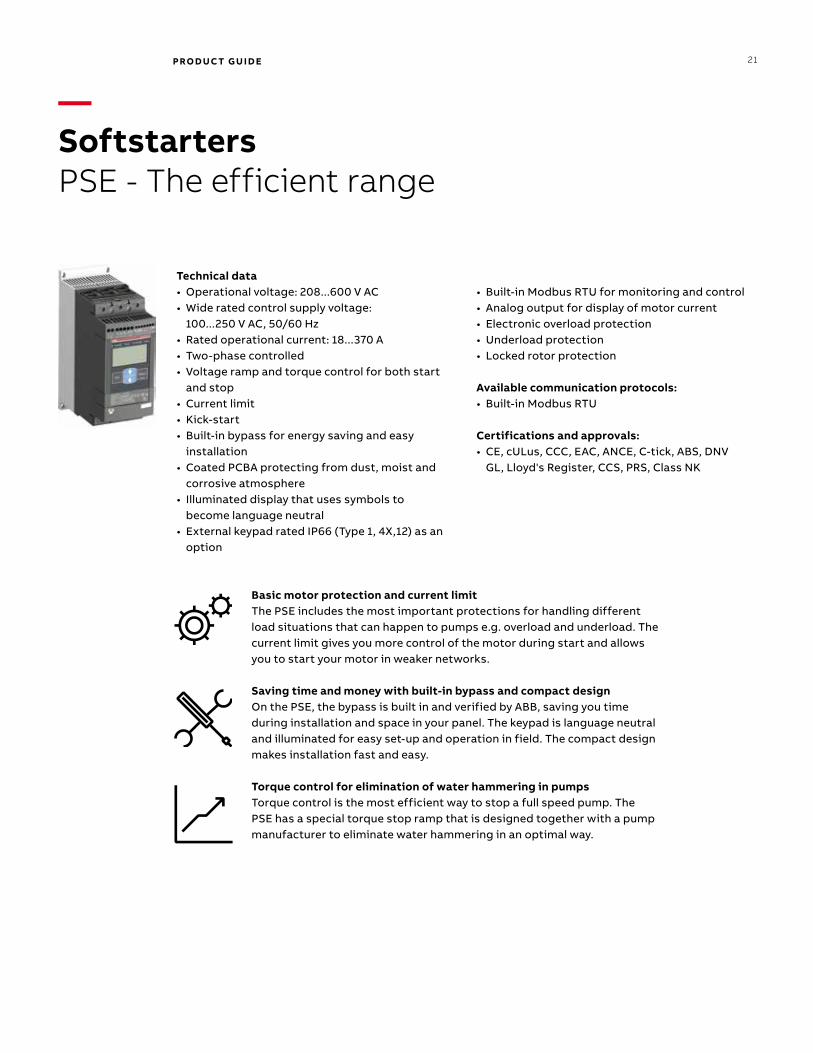
—SoftstartersPSE - The efficient range
Technical data• Operational voltage: 208...600 V AC• Wide rated control supply voltage:
100...250 V AC, 50/60 Hz • Rated operational current: 18...370 A• Two-phase controlled• Voltage ramp and torque control for both start
and stop• Current limit • Kick-start• Built-in bypass for energy saving and easy
installation• Coated PCBA protecting from dust, moist and
corrosive atmosphere• Illuminated display that uses symbols to
become language neutral• External keypad rated IP66 (Type 1, 4X,12) as an
option
• Built-in Modbus RTU for monitoring and control• Analog output for display of motor current• Electronic overload protection• Underload protection • Locked rotor protection
Available communication protocols:• Built-in Modbus RTU
Certifications and approvals:• CE, cULus, CCC, EAC, ANCE, C-tick, ABS, DNV
GL, Lloyd's Register, CCS, PRS, Class NK
Basic motor protection and current limitThe PSE includes the most important protections for handling different load situations that can happen to pumps e.g. overload and underload. The current limit gives you more control of the motor during start and allows you to start your motor in weaker networks.
Saving time and money with built-in bypass and compact designOn the PSE, the bypass is built in and verified by ABB, saving you time during installation and space in your panel. The keypad is language neutral and illuminated for easy set-up and operation in field. The compact design makes installation fast and easy.
Torque control for elimination of water hammering in pumpsTorque control is the most efficient way to stop a full speed pump. The PSE has a special torque stop ramp that is designed together with a pump manufacturer to eliminate water hammering in an optimal way.

22 PRO D U C T G U I D E
—SoftstartersPSTX - The advanced range
Technical data• Operational voltage: 208...690 VAC • Wide rated control supply voltage:
100...250 V, 50/60 Hz• PSTX rated operational current: 30...1250 A
(inside-delta: 2160 A)• Three-phase controlled• Both in-line and inside-delta connection • Coated circuit boards protecting from dust,
moist and corrosive atmosphere• Detachable keypad rated IP66 (Type 1, 4X,12) • Graphical display with 17 languages for easy
setup and operation• Built-in bypass for energy saving and easy
installation • Built-in Modbus RTU for monitoring and control
• Support for all major communication protocols• Analog output for measurement of current,
voltage, power factor etc.
Available communication protocols:• Built-in Modbus RTU• Anybus/FBP• Modbus RTU• PROFIBUS• DeviceNet• EtherNet/IP• PROFINET
Certifications and approvals:• CE, cULus, CCC, EAC, ANCE, C-tick, ABS, DNV
GL, Lloyd's Register, CCS, PRS, Class NK
Complete motor protection The PSTX offers complete motor protection in only one unit and is able to handle both load and network irregularities. PT-100, earth fault protection and over/under voltage protection along with many other functions keep your motor safer than ever
Built-in bypass saves time and energyWhen reaching full speed, the PSTX will activate its bypass. This saves energy while reducing the softstarter’s heat generation. On the PSTX, the bypass is built in and verified by ABB, saving you time during installation and space in your panel.
Complete control of pumpsTime to use your processes to their full potential. The PSTX features many application enhancing features, including torque control: the most efficient way to start and stop pumps. The pump cleaning feature can reverse pump flow and clean out pipes, securing uptime of your pump system.

PRO D U C T G U I D E 23
—A lifetime of peak performance
You’re in control of every life cycle phase of your drives and softstarters. At the heart of drive and softstarter services is a four-phase product life cycle management model. This model defines the services recommended and available throughout drives and softstarters lifespan.
— Now it’s easy for you to see the exact service and maintenance available for your drives and softstarters.
Product is in active sales and manufacturing phase.
Full range of life cycle services is available.
Full range of life cycle services is available.
Product enhancements may be available through upgrade and retrofit solutions.
Limited range of life cycle services is available.
Spare parts availability is limited to available stock.
Product is no longer available.
Product is no longer available.
ABB drives and softstarters life cycle phases explained:
Full range of life cycle services and supportLimited range of life cycle
services and supportReplacement and
end-of-life services
Serial production has ceased. Product may be available for plant extensions, as a spare part or for installed base renewal.
Pro
du
ctS
ervi
ces
Replacement and end-of-life services are available.
Keeping you informedWe notify you every step of the way using life cycle status statements and announcements.
Your benefit is clear information about your drives’ status and precise services available. It helps you plan the preferred service actions ahead of time and make sure that continuous support is always available.
Step 1Life Cycle Status AnnouncementProvides early information about the upcoming life cycle phase change and how it affects the availability of services.
Step 2Life Cycle Status StatementProvides information about the drive's current life cycle status, availability of product and services, life cycle plan and recommended actions.
Active Classic Limited Obsolete

24 PRO D U C T G U I D E
—Introducing the most extensive drives and softstarters portfolio in the world

PRO D U C T G U I D E 25
ABB low voltage AC drivesThe ABB low voltage AC drives product range, from 0.18 to 5600 kW, is the widest available from any manufacturer. These drives are the global benchmark that signifies reliability, simplicity, flexibility and ingenuity throughout the entire life cycle of the drive.
Several ABB drives feature calculators that provide energy consumption data. This information can be used to further analyze and tune a process for even greater energy savings.
The portfolio is supported by a selection of PC tools, fieldbus and communication options.
ABB micro drivesABB micro drives are suitable for many low power applications such as pumps, fans and conveyors. The focus in our design has been the easy integration into machines, which provides flexible mounting alternatives and straightforward commissioning.
ABB general purpose drivesABB general purpose drives are ideal in those situations where there is a need for simplicity to install, commission and use. They are designed to control a wide range of standard drives applications, including pump, fan and constant torque use, such as conveyors.
ABB machinery drivesABB machinery drives can be configured to meet the precise needs of industries and order-based configuration is an integral part of the offering. Covering a wide power and voltage range with standard and optional features, the drives are readily programmable, making their adaptation to different applications easy.
ABB industrial drivesThe ABB industrial drive portfolio is designed for heavy industrial applications such as those found in pulp and paper, metals, mining, cement, power, chemical, oil and gas, water and wastewater and food and beverage. Drives adapted and approved for use in the marine environment are also included within this portfolio.
Industry specific drivesOur industry specific ABB drives provide our customers with dedicated drive solutions for AC motor control used in industries such as HVAC and water and wastewater. Working closely with these industries, we have developed targeted functionality to help you improve your overall operating performance while also helping to reduce energy use. Built-in application macros in the drives help you easily setup and tailor processes.
ABB DC drivesABB’s DC drive portfolio, from 9 to 18000 kW, provides the highest power-to-size ratio on the market. The drives are designed for most industries including metals, cement, mining, pulp and paper, printing, food and beverage, wire manufacturing, test rigs, ski lift and cranes. ABB DC drives are available as complete cabinets, modules for cabinet assembly, and as retrofit kits. With built-in field exciters and integrated PLC’s, they are the best DC drives choice for all new and retrofit applications.
ABB softstartersA softstarter is the optimal compromise between a direct on-line or star delta starter and an advanced variable speed drive in many motor applications. Like direct on-line or star delta starters, it is used in full-speed applications. Like variable speed drives, it can perform soft starts and stops.
To find more information please visit: www.abb.com/drives www.new.abb.com/low-voltage/products/softstarters

26 PRO D U C T G U I D E
—Services to match your needs
Your service needs depend on your operation, life cycle of your equipment and business priorities. We have identified our customers’ four most common needs and defined service options to satisfy them. What is your choice to keep your drives at peak performance?
Is uptime your priority?
Keep your drives and softstarters running with precisely planned and executed maintenance. Example services include:• ABB Ability Life Cycle Assessment• Installation and Commissioning• Spare Parts• Preventive Maintenance• Reconditioning• ABB Drive and Softstarter Care agreement• Drive and Softstarter Exchange
Is rapid response a key consideration?
If your drives and softstarters require immediate action, our global network is at your service. Example services include:• Technical Support• On-site Repair• ABB Ability Remote Assistance• Response time agreements• Training
Operational efficiency
Rapid response

27
The future of your drives and softstarters depends on the service you choose. Whatever you choose, it should be a well-informed decision. No guesswork. We have the expertise and experience to help you find and implement the right service for your drive equipment. You can start by asking yourself these two critical questions:
• Why should my drive and softstarter be serviced?• What would my optimal service options be?
From here, you have our guidance and full support along the course you take, throughout the entire lifetime of your drives.
Your choice, your business efficiencyABB Drive Care agreement lets you focus on your core business. A selection of predefined service options matching your needs provides optimal, more reliable performance, extended drive and softstarter lifetime and improved cost control. So you can reduce the risk of unplanned downtime and find it easier to budget for maintenance.
We can help you more by knowing where you are!Register your drive and softstarter at www.abb.com/drivereg for extended warranty options and other benefits.
—Drives and softstarters serviceYour choice, your future
Need to extend your assets’ lifetime?
Maximize your drive’s lifetime with our services. Example services include:• ABB Ability Life Cycle Assessment• Upgrades, Retrofits and Modernization• Replacement, Disposal and Recycling
Is performance most critical to your operation?
Get optimal performance out of your machinery and systems. Example services include:• ABB Ability Remote Services• Engineering and Consulting• Inspection and Diagnostics• Upgrades, Retrofits and Modernization• Workshop Repair• Tailored services
Life cycle management
Performance improvement

— For more information, please contact your local ABB representative or visit
www.abb.com/driveswww.new.abb.com/low-voltage/products/softstarters
LVD
-PH
PG
01U
-EN
R
EV
W E
ffec
tive
: 3/3
/20
20