for more information on obtaining copies of this ...department/deptdocs.nsf/ba3468a2a... ·...
TRANSCRIPT

For more information on obtaining copies of this publication contact:Alberta Agriculture and Rural DevelopmentPublications OfficeJ.G. O'Donoghue Building7000-113 StreetEdmonton, AB T6H 5T6Phone toll free: 1-800-292-5697 Fax: (780) 422-8835
orAlberta Environment and Sustainable Resource Development Information Centre Main Floor, 9920-108 Street Edmonton, Alberta T5K 2M4 Phone: (780) 427-2700 Fax: (780) 427-4407
©Copyright 1996First Edition: 1996
Second Edition: 1998Reprinted: 1999
Third Edition: 2000Fourth Edition: 2005Fifth Edition: 2006Sixth Edition: 2007
Seventh Edition: 2010Eighth Edition: 2013
All rights reserved by Her Majesty the Queen in right of Alberta. Materials may not be reproduced without the permission of
Alberta Agriculture and Rural Development
4.5 M
The publication can be viewed on-line at: http://www.agric.gov.ab.ca/
then click on the search button and type in "Water Wells" in the search box.
AcknowledgementsWritten by: Bob Buchanan, Alberta Agriculture and Rural Development Nga De La Cruz, Alberta Environment and Sustainable Resource Development Jennifer Macpherson, Alberta Environment and Sustainable Resource Development Ken Williamson, Alberta Agriculture and Rural Development
Technical Input: John Lebedin, Agriculture and Agri-Food Canada David Toop, Agriculture and Agri-Food Canada Terry Dash, Agriculture and Agri-Food Canada
Reviewers: Darcy Fitzgerald, Alberta Agriculture and Rural Development Myron Hawryliw, Agriculture and Agri-Food Canada Dave Kiely, Agriculture and Agri-Food Canada Jennifer Macpherson, Alberta Environment and Sustainable Resource Development Lyle Penrod, GWIETCO
Revision: Tony Cowen, Agriculture and Agri-Food Canada Jennifer MacPherson, Alberta Environment and Sustainable Resource Development Murray Tenove, Alberta Agriculture and Rural Development Melissa Orr-Langner, Alberta Agriculture and Rural Development
Project Development: Bob Buchanan, Alberta Agriculture and Rural Development Faye Douglas Phillips, Alberta Agriculture and Rural Development Lewis Fahner, Alberta Environment and Sustainable Resource Development Darcy Fitzgerald, Alberta Agriculture and Rural Development Myron Hawryliw, Agriculture and Agri-Food Canada Dave Kiely, Agriculture and Agri-Food Canada Neil MacAlpine, Alberta Agriculture and Rural Development Jennifer Macpherson, Alberta Environment and Sustainable Resource Development Pat Osachuk, Agriculture and Agri-Food Canada Ken Williamson, Alberta Agriculture and Rural Development
Special thanks to Lewis Fahner (AESRD) and Len Fullen (ARD) who cared enough to bring forth an idea and a group of individuals who shared their concerns.
Thank you to the Alberta Water Well Drilling Association, the Canadian Ground Water Association, and the Canadian Association of Geophysical Contractors for their help in providing revisions to the original manual.

Educational Design: Instructional Design Unit, Coordinator of the Home Study Program Alberta Agriculture and Rural Development
Maureen Barnes, Instructional Designer
Eugene Balogh, Desktop Publisher
Lois Hameister, Editor
Faye Douglas Phillips, Home Study Coordinator
George Cassady, Timber Line Graphics
Agricultural Engineering: Alberta Agriculture and Rural Development
Joanna Fyck, Illustrations
Crystal Lively Illustrations
George Ragan, Illustrations
We also acknowledge the following sources of information used in the preparation of these resource materials:
- Driscoll, F. G., 1986. Groundwater and Wells, 2nd Edition. Johnson Filtration Systems Inc., St. Paul, Minnesota.
- Canadian Ground Water Association, 1995. Guidelines for Water Well Construction. Canadian Ground Water Association, Lousana, Alberta.
Table of ContentsIntroduction—How to Use This Workbook ...........................................................................i
Contents ....................................................................................................................................i
Other Features of the Workbook ...........................................................................................iii
Module 1—Understanding Groundwater .............................................................................1
What is Groundwater? ............................................................................................................1Aquifers and Aquicludes ...................................................................................................2Confined and Unconfined Aquifers ..................................................................................2
Types of Aquifers in Alberta ...................................................................................................3
Groundwater Movement .........................................................................................................4
Groundwater Recharge ...........................................................................................................4
Factors Affecting Groundwater Quality ................................................................................5Depth from Ground Surface .............................................................................................5Permeability of Sediments................................................................................................6Chemical Makeup of Sediments .......................................................................................6Climatic Variations ...........................................................................................................6
Geology and Groundwater Supplies in Alberta .....................................................................7
Module 2—Planning Your Water System .............................................................................9
Why Plan? ................................................................................................................................9
Steps to Planning Your Water System .................................................................................10Determine Water Requirements ....................................................................................10Complete an Inventory of Water Sources ......................................................................10
Water Source Options ...........................................................................................................11Wells ................................................................................................................................11Dugouts ............................................................................................................................11
Other Planning Considerations ............................................................................................12Test Water Quality .........................................................................................................12Treat Water .....................................................................................................................12Monitor the Supply .........................................................................................................12Maintain the Well and Water System ...........................................................................12Protect from Contamination ...........................................................................................12
Average Daily and Annual Water Requirements Worksheet ............................................. 13
Sizing of Water Systems Worksheet ....................................................................................15
Farm Water Supply Inventory Worksheet ...........................................................................16
Module 3—Design and Construction of Water Wells .......................................................17
Choosing a Licensed Water Well Contractor .......................................................................17
Choosing a Well Site..............................................................................................................18
Well Design Considerations ..................................................................................................20Well Depth .......................................................................................................................20Types of Wells .................................................................................................................20Casing Size and Type ......................................................................................................22Intake Design ..................................................................................................................22Annular Seal ...................................................................................................................24Well Cap ..........................................................................................................................24
Well Completion ....................................................................................................................25Well Development ...........................................................................................................25Yield Test .........................................................................................................................26Disinfecting the Well ......................................................................................................26
Module 4—Water Well Drilling Agreements ......................................................................27
Water Well Drilling Agreement Example ............................................................................27
Water Well Casing Specifications .........................................................................................33
Water Well Drilling Report ...................................................................................................34
Water Well Drilling Agreement Form ..................................................................................35

Module 5—Monitoring and Maintenance of Your Water Well .......................................37
Water Level Measurements ..................................................................................................37How to Measure Water Levels .......................................................................................38Interpreting Water Levels ..............................................................................................39
Water Quality Measurements ..............................................................................................43Bacteriological Analysis ..................................................................................................43Chemical Analysis ...........................................................................................................43Non-routine Testing ........................................................................................................44Sampling ..........................................................................................................................44Interpreting Results........................................................................................................44
Water Well Monitoring Log Worksheet ...............................................................................45
Module 6—Shock Chlorination .............................................................................................47
Signs of Nuisance Bacteria ..................................................................................................48Slime Growth ..................................................................................................................48Rotten Egg Odour ...........................................................................................................48Increased Staining Problems..........................................................................................48
Shock Chlorination Method ..................................................................................................49Effectiveness of Shock Chlorination ..............................................................................49Shock Chlorination Procedure for Drilled Wells ...........................................................50Modified Procedure for Large Diameter Wells ..............................................................53
Calculating Water and Chlorine Requirements for Shock Chlorination Worksheet ......... 54
Module 7—Troubleshooting Water Well Problems ...........................................................55
Causes of Well Problems .......................................................................................................55Improper Well Design and Construction .......................................................................56Incomplete Well Development ........................................................................................56Borehole Stability Problems ...........................................................................................56Mineral Incrustation .......................................................................................................57Biofouling ........................................................................................................................57Corrosion .........................................................................................................................57

Over-pumping .................................................................................................................58Dissolved Gas in Water ..................................................................................................58Aquifer Problems ............................................................................................................58
Troubleshooting Guide ..........................................................................................................59Symptom #1 — Reduced Well Yield ...............................................................................60Symptom #2 — Sediment in Water ................................................................................61Symptom #3 — Change in Water Quality .....................................................................62Symptom #4 — Dissolved Gas in the Water ..................................................................63
Module 8—Protecting Your Well From Contamination ..................................................65
Poor Well Construction .........................................................................................................65
Old Wells ................................................................................................................................66
Well Pits .................................................................................................................................67
Farm Water Hydrants Installed in a Well or Well Pit ........................................................ 68
Poor Sewage Systems ............................................................................................................68
Seismic Shot Holes ................................................................................................................69
Over-Application or Improper Storage of Manure or Fertilizer ......................................... 69
Hazardous Material Storage .................................................................................................69
Fuel Storage Tanks ...............................................................................................................70
Pesticide Contamination .......................................................................................................70
Contamination During Maintenance ...................................................................................70
Module 9—Plugging Abandoned Wells ................................................................................73
Who is Responsible? ..............................................................................................................74
Process of Plugging a Well ....................................................................................................74Preparation ......................................................................................................................74Materials .........................................................................................................................75Method .............................................................................................................................76
Steps to Plugging a Well .......................................................................................................77

Special Problems ...................................................................................................................78
Record of Well Plugging Worksheet .....................................................................................79
Module 10—Groundwater Management .............................................................................81
Inventory .........................................................................................................................82Allocation and Licensing ................................................................................................83Obtaining a Licence ........................................................................................................84Protection and Conservation ..........................................................................................85
Module 11—Contacts For More Information .....................................................................87
Module 12—Other Resources .................................................................................................91
General Water-Related Information ..............................................................................91Planning Your Water System .........................................................................................91Design and Construction of Water Wells .......................................................................92Monitoring Your Water Well .........................................................................................92Shock Chlorination of Water Wells ................................................................................92Troubleshooting Water Well Problems ..........................................................................93Protecting Your Well From Contamination...................................................................93Groundwater Management ............................................................................................94
Glossary ......................................................................................................................................95
List of Figures
Hydrologic Cycle ......................................................................................................................1
Types of Aquifers .....................................................................................................................3
Bored Well ..............................................................................................................................20
Well Completions ...................................................................................................................21
Annular Seal ..........................................................................................................................24
Dip Tube .................................................................................................................................38
Pumping Water Level Drawdown ........................................................................................41

Siphoning Chlorine Solution .................................................................................................52
Perforated Well Liner and Well Screen ................................................................................56
Annular or Casing Seal .........................................................................................................66
Multi-Aquifer Well Completion ............................................................................................66
Well Pit...................................................................................................................................67
Pitless Adaptor ......................................................................................................................67
Farm Water Hydrant ............................................................................................................68
Poor Sewage Systems ............................................................................................................68
Well Contamination ..............................................................................................................73
Contamination from an Abandoned Well ............................................................................73
Bridging .................................................................................................................................76
Cutting Off the Casing and Mounding the Clay ..................................................................77

Introduction — How to Use This Workbook
i
How to Use This WorkbookThere are 12 modules in this workbook, many with worksheets for you to complete. There
is a pocket on the back cover for storing your worksheets. The pocket on the front cover is for storing other well documents like your driller's report. Extra copies of worksheets are included in the back cover pocket. Some topics will be of more interest to you than others, but we urge you to start with Module 1 “Understanding Groundwater” and then move on to topics that relate to your situation.
A video has been developed to be used in conjunction with the workbook. To obtain the Water Wells That Last video, see page 92 in Module 12 “Other Resources”.
ContentsModule 1 Understanding Groundwater
Groundwater is vulnerable to overuse and misuse. With the information in this module, you will better understand the complexities of groundwater and can use and protect the groundwater on your land so that future generations can depend on the resource. You’ll also look at factors that affect the quantity and quality of groundwater.
Module 2 Planning Your Water SystemUse this module to assess whether your water source can meet your needs. You will
learn how to plan a water system designed to meet your needs today and in the future. Worksheets allow you to calculate daily and annual water requirements and take a farm water supply inventory.
Module 3 Design and Construction of Water WellsAlthough you need to hire a licensed water well contractor to design and construct your
well and use suitable materials, it is important that you understand the process. You’ll learn about choosing a suitable well site, proper design and completion.
Module 4 Water Well Drilling AgreementsThis module gives an example of items that you and your licensed water well contractor
should discuss and agree to before starting any water well drilling.
All references to volumes or flow rates are in Imperial measurements unless otherwise specified.

ii
Introduction — How to Use This Workbook
Module 5 Monitoring and Maintenance of Your Water WellAn effective monitoring program will identify changes in water levels and water quality.
This module outlines how to measure water levels and water quality on an ongoing basis. A water well monitoring worksheet is included.
Module 6 Shock ChlorinationThis module outlines the importance of shock chlorination for well maintenance.
Shock chlorination is used to control bacteria in water wells. Uncontrolled, bacteria can cause reduced well yield, restricted water flow, staining, odours and plugging of water treatment equipment. This module outlines a procedure you can do yourself to shock chlorinate your well.
Module 7 Troubleshooting Water Well ProblemsThere are many causes of water well problems. This module outlines some of the causes
and provides a troubleshooting guide. The troubleshooting guide identifies four symptoms — reduced well yield, sediment in the water, change in water quality and spurting household taps — and explains what to check for and how to correct the problem.
Module 8 Protecting Your Well from ContaminationOnce a well is contaminated, it is difficult to remove the contaminant. This module aims
at preventing contamination from poor well design and construction, old wells, well pits, farm water hydrants, inadequate sewage systems, seismic shot holes, over-application of manure or improper storage of manure or fertilizer, hazardous material storage, fuel storage tanks, pesticides and contamination during well maintenance.
Module 9 Plugging Abandoned WellsAbandoned wells are a threat to groundwater quality and a safety hazard for children
and animals. This module outlines the steps to plugging a well. Some steps you can do yourself and others you may want to hire a licensed water well contractor to complete.
Module 10 Groundwater ManagementThis module outlines how the province is protecting groundwater from overuse and
contamination. It also covers groundwater licensing as well as strategies that deal with inventory, allocation, protection and conservation.
Introduction — How to Use This Workbook
iii
Module 11 Contacts for More InformationThis module provides a list of agencies and organizations who can help you with your rural
water needs and problems.
Module 12 Other ResourcesUse this module to access other publications and videos on water resources.
GlossaryUse the glossary to help understand various terms used in this manual.
Other Features of the Workbook
This illustrates an example. Study the example before you attempt the related exercise or do your own calculations.
This symbol tells you to complete a worksheet found at the end of the module. Working copies of the worksheets are found in the back cover pocket. Use the back pocket to store completed worksheets.
This symbol tells you to refer to the Water Wells That Last video.
This symbol tells you to check off applicable items in order to identify a problem.
Worksheet
Checklist


Module 1 — Understanding Groundwater
1
For more information refer to the Water Wells That Last video (Part I — Planning and Construction).
Understanding GroundwaterGroundwater is a priceless resource lying beneath most of Alberta’s land surface. About
90 percent of rural Albertans rely on groundwater for a household water supply. Reliance on groundwater continues to increase in rural Alberta because of the steady increase in livestock populations and groundwater requirements for oil recovery purposes.
Because it is a “hidden” resource, groundwater is vulnerable to overuse and water quality degradation. This module provides basic information about how groundwater occurs below the ground surface that will help understand how to use and protect groundwater in a manner that will ensure plentiful supplies ermain for future generations.
What is Groundwater?Groundwater is one component of the earth’s water cycle. The water cycle, called the
hydrologic cycle, involves the movement of water as water vapour, rain, snow, surface water and groundwater. The earth’s water is constantly circulating from the earth’s surface up into the atmosphere and back down again as precipitation (see Figure 1, Hydrologic Cycle).
Figure 1 Hydrologic Cycle

2
Module 1 — Understanding Groundwater
Some precipitation that falls to the ground surface infiltrates the ground and becomes groundwater. Groundwater is defined as sub-surface water that fills openings and pore spaces in soil and rock layers. Below the ground surface is an unsaturated zone, which water travels through, to reach lower zones. The water table is the point at which the ground is completely saturated. Below this level the pore spaces between every grain of soil and rock crevice completely fill with water.
Aquifers and AquicludesThe layers of soil and rock below the water table are classified in two broad categories:
Aquifers
Aquicludes.
Aquifers are water bearing layers (or formations) that yield water to wells in usable amounts. Typical aquifers are made of sand, gravel or sandstone. These materials have large enough connected pore spaces between grains that water moves freely. Coal and shale are more tightly compacted but may also be suitable aquifer materials if they are fractured (or cracked) enough to allow water to move through them.
Aquicludes are water bearing formations that cannot yield adequate water for wells. Examples of these are clay and unfractured shale and coal. The pore spaces between grains of these materials are so small that water moves through them extremely slowly.
Confined and Unconfined AquifersUnconfined aquifers are exposed directly to the atmosphere through openings in the
soil. The volume of water in unconfined aquifers is mainly dependent on seasonal cycles of precipitation that refills the aquifer. A water table aquifer is an example of an unconfined aquifer (see Figure 2, Types of Aquifers).
A confined aquifer is trapped below an upper confining layer of rock, clay or shale. When a well is drilled into a confined aquifer, the water level in the well rises above the upper boundary of the aquifer. Aquifers that are completely saturated with water and under pressure are called artesian aquifers. The artesian aquifer shown in Figure 2, Types of Aquifers, is an example of a confined aquifer. A flowing artesian well results when the pressure in the aquifer raises the water level above the ground surface.

Module 1 — Understanding Groundwater
3
Types of Aquifers in AlbertaThere are two main types of aquifers in Alberta: Surficial Bedrock.The amount of water available in each type varies depending on the geological makeup
of the area.
Surficial aquifers are shallow sand and gravel aquifers that typically occur between 10-30 m (33-100 ft.). They are important sources of water for many parts of Alberta.
Buried valleys are much like our river system. In Alberta, there is a vast network of interconnected valleys located beneath the land surface. These buried valleys appear to have been carved into the upper portion of the underground rock formations and sometimes contain extensive deposits of sand and gravel. They range in depth from 15-90 m (50-300 ft.) and in width from under .4 km (1/4 mi.), to over 16 km (10 mi.).
Figure 2 Types of Aquifers
4
Module 1 — Understanding Groundwater
They can offer excellent sites for high yielding wells that can produce up to 500 gallons per minute (gpm). Consequently, there has been considerable effort by hydrogeologists and licensed water well contactors over the past 10 to 20 years to identify the locations of these high yielding aquifers. It is expected that in years to come these buried valleys will become a major source of water supply for agricultural and industrial purposes throughout the province. If the exact locations, yield and water quality of these sources were known, community wells and pipelines could replace individual dugouts and marginal wells in areas with little other groundwater. Properly managed pipelines from wells tapping into these formations would ensure a long-term water supply.
Bedrock aquifers in Alberta are usually composed of sandstone, fractured shale and coal. These aquifers are generally sufficient for most domestic needs; however, larger livestock operations often struggle to meet all of their water requirements from wells drilled into bedrock aquifers. Fractured shales and coals are generally much lower yielding than sandstone (shale and coal yield <1 to 30 gpm; sandstone yields 1 to 500 gpm). Sandstone aquifers that yield more than 50 gpm are limited to a small portion of the province. These few high yielding aquifers are often tapped for municipal use.
Groundwater MovementGroundwater is continually moving, but generally very slowly. Gravity is the major
driving force and thus groundwater is always moving from areas of higher elevation to lower elevation. Notice the water table in Figure 2, Types of Aquifers, is not level. It slopes toward the stream indicating groundwater moves in that direction. The water in the Artesian (confined) aquifer is also moving away from the area of higher elevation due to gravity.
Knowing the direction of groundwater movement is increasingly important because of the danger of contaminating groundwater supplies. Shallow water table aquifers are especially susceptible to surface contaminants such as sewage, manure, pesticides and petroleum products when they enter the ground at higher elevations, or upslope from the well. Proper well location and separation distances from potential contaminants reduce this risk.
Groundwater RechargeAquifers can be recharged (or refilled) directly by precipitation moving down through
the soil and rock layers and into these water bearing formations. They can also be recharged by infiltration from surface water sources such as lakes, rivers, creeks and sloughs. Conversely, groundwater may discharge to surface water sources. The quantity of groundwater discharge may be a significant portion of input into the surface water source and can affect water quality accordingly.

Module 1 — Understanding Groundwater
5
Natural groundwater recharge is affected by human activities on the ground surface. For example, the drainage of sloughs removes water that would have infiltrated to eventually become groundwater. A reduction in groundwater recharge can seriously reduce the water level in nearby shallow wells. This groundwater/surface water interaction must be carefully considered because the development of either resource will affect the quantity and quality of the other.
Factors Affecting Groundwater Quality An understanding of the factors that affect groundwater quality can help you make
decisions on well depth and the best water quality for a particular application. There are several factors that affect groundwater quality:
Depth from ground surface
Permeability and chemical makeup of the sediments through which groundwater moves
Climatic variations.
Depth from Ground SurfaceWater is the world’s greatest and most abundant solvent. It attempts to dissolve
everything it comes in contact with. As a result, the longer groundwater takes to move through the sediments, the more mineralized it becomes. Thus, shallow groundwater aquifers have a lower level of mineralization, or total dissolved solids (TDS), than deeper aquifers. Water from deeper groundwater aquifers typically has a much longer trip to its destination and thus it is usually more mineralized.
While shallow wells have lower levels of TDS, they do have higher levels of calcium, magnesium and iron than deeper wells. High levels of these minerals make the water “hard.” Deeper wells have higher levels of sodium and lower levels of hardness, making the water “soft.” The reason is that deeper sediments and rock formations contain higher levels of sodium and as water moves downward through the sediment and rock formations, a natural ion exchange process occurs. Calcium, magnesium and iron in the groundwater are exchanged for sodium in the sediment and rock formations. The result is groundwater with higher levels of sodium and little or no hardness. The process is identical to what occurs in an automatic water softener, except in this case, it is a natural phenomenon.
Total dissolved solids (TDS) means the quantity of dissolved minerals in the water.

6
Module 1 — Understanding Groundwater
Permeability of SedimentsGroundwater is stored in the small spaces between particles that make up the sediment
and rock formations. These pore spaces are interconnected and groundwater moves slowly through them. Permeability is a measure of the ease with which groundwater travels through the pore spaces. Groundwater moves very slowly through sediments with low permeability, such as clay. This allows more time for minerals to dissolve. In contrast, sediments with high permeability, such as sand, allow groundwater to move more quickly. There is less time for minerals to dissolve and thus the groundwater usually contains lower levels of dissolved minerals.
There is also a difference in dissolved solids between groundwater in recharge zones and water in discharge zones. Recharge zones are uplands areas where precipitation readily enters the ground through permeable, sandier sediments. Generally, water in recharge zones has a low level of mineralization. Discharge areas are low areas where groundwater flow eventually makes its way back to (or near) the ground surface. Groundwater found in such areas can be extremely high in minerals such as sodium, sulfates and chlorides. Examples are saline seeps, sloughs and lakes.
Chemical Makeup of SedimentsAnother factor affecting groundwater quality is the chemical makeup of minerals. Some
chemicals are more soluble than others, making them more likely to become dissolved in the water. For example, groundwater in contact with sediments containing large concentrations of sodium, sulfate and chloride will become mineralized at a faster rate than if other chemicals were present.
Climatic VariationsClimatic variations such as annual rainfall and evaporation rates also play an important
role in groundwater quality. In semi-arid regions discharging groundwater often evaporates as it approaches the surface. The minerals from the water are deposited in the soil, creating a salt buildup. Precipitation infiltrating through the soil can redisslove the salts, carrying them back into the groundwater. For example, in east central and southern Alberta where annual precipitation is from 25-40 cm (10-16 in.) and the evaporation rate is high, TDS are about 2500 parts per million (ppm). In areas with higher precipitation and lower evaporation rates, precipitation that reaches groundwater is less mineralized. For example, in western Alberta where annual precipitation is more than 45 cm (18 in.) groundwater in surficial deposits contains less than 800 ppm of TDS.
A basic understanding of the factors that affect groundwater quality can help you make decisions on well depths and the best water quality for a given application.
Module 1 — Understanding Groundwater
7
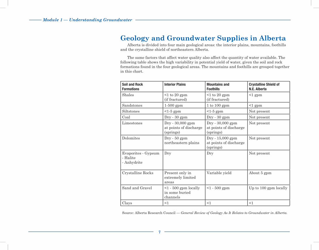
Geology and Groundwater Supplies in AlbertaAlberta is divided into four main geological areas: the interior plains, mountains, foothills
and the crystalline shield of northeastern Alberta.
The same factors that affect water quality also affect the quantity of water available. The following table shows the high variability in potential yield of water, given the soil and rock formations found in the four geological areas. The mountains and foothills are grouped together in this chart.
Source: Alberta Research Council — General Review of Geology As It Relates to Groundwater in Alberta.
Soil and RockFormations
Interior Plains Mountains andFoothills
Crystalline Shield ofN.E. Alberta
Shales <1 to 20 gpm(if fractured)
<1 to 20 gpm(if fractured)
<1 gpm
Sandstones 1-500 gpm 1 to 100 gpm <1 gpm
Siltstones <1-5 gpm <1-5 gpm Not present
Coal Dry - 30 gpm Dry - 30 gpm Not present
Limestones Dry - 30,000 gpmat points of discharge(springs)
Dry - 30,000 gpmat points of discharge(springs)
Not present
Dolomites Dry - 50 gpm northeastern plains
Dry - 15,000 gpmat points of discharge(springs)
Not present
Evaporites - Gypsum- Halite- Anhydrite
Dry Dry Not present
Crystalline Rocks Present only in extremely limited areas
Variable yield About 5 gpm
Sand and Gravel <1 - 500 gpm locallyin some buried channels
<1 - 500 gpm Up to 100 gpm locally
Clays <1 <1 <1

8
Module 1 — Understanding Groundwater

Module 2 — Planning Your Water System
9
Planning Your Water System This module helps you assess whether your water source has adequate capacity to meet
your needs. Water sources are covered in detail. You will also get an overview of the planning considerations and benefits of a well-designed water system.
A water system may include:
Water sources
Pumps
Pressure system and additional storage if required
Distribution system including pipelines, automatic waterers, hydrants and home plumbing
Water treatment equipment.
Why Plan?Often little thought and foresight are given to planning a farm or home water system. On
the surface, a water system seems no more than an automatic pump and storage tank that delivers water under pressure to the household. There are other important aspects, such as how much water is available, the pressure requirements, water quality and provisions for watering a garden and fire fighting. When planning your water system, consider all the uses (current and potential) of water in your home and business. Include such things as:
Livestock watering
Cleaning barn floors and equipment
Irrigation of gardens and greenhouses
Egg and milk production
Fire protection.
A water system that is well planned and designed costs more initially but saves money in the end. Costly changes to correct errors are reduced and you have a convenient and reliable water supply, provided you monitor and maintain the system (see Module 5 "Monitoring & Maintenance of Your Water Well" and Module 6 "Shock Chlorination").
For more specific information on pumps, pressure tanks, pipeline sizing, water quality and treatment equipment, contact a water specialist with Alberta Agriculture and Rural Development. You could also contact the Alberta Water Well Drilling Association or your local licensed water well contractors. See Module 11 "Contacts for More Information".
You should determine water quality and availability before you buy a new property or build a new home. If there is an existing well, you should have it yield tested to establish its performance. You should also have the water tested for quality.
For more information refer to the Water Wells That Last video (Part I — Planning and Construction).

10
Module 2 — Planning Your Water System
Steps to Planning Your Water SystemIn order to plan your water system you need to:
Determine water requirements
Complete an inventory of water sources.
Determine Water RequirementsThe first step to planning is to determine your water requirements. Look beyond your
current requirements and consider any changes you may be making in the next few years. For example, is another family moving to the farm? Are you considering diversifying to include a market garden? Use the worksheets "Daily and Annual Water Requirements" and "Sizing of Water Systems" included in the pocket on the back cover to calculate your daily, annual and peak use requirements. Sample copies are at the back of the module.
Complete an Inventory of Water SourcesThe next step to planning is to complete an inventory of all existing well and surface
water sources. Record production rates, storage volumes and any previous problems with water quantity or quality for each water source. Completing an inventory will show if there is adequate water supply to meet your needs year round. Use the worksheet, "Farm Water Supply Inventory," included in the back cover pocket to list all the water sources available to you.
A well-planned water system should also have a backup or second water source in case of pump or water source failure. Water sources that can easily be connected using underground piping provide the flexibility required in emergencies.
If you have some doubt about the adequacy of your existing water sources, take time to check all the options before choosing to drill a new well. There may be ways of increasing well yields or water storage to meet your needs. In some situations a well can comfortably keep up to daily requirements but not peak demands. The addition of a cistern with one-half to one day storage may be all that is required.
Worksheet
Complete "Average Daily and Annual Water Requirements" worksheet and "Sizing of Water Systems" worksheet. Samples of these worksheets are found at the end of this module. Working copies are found in the back cover pocket. Store these completed worksheets in the back pocket.
Worksheet
Complete "Farm Water Supply Inventory" worksheet. A sample copy is found at the end of this module. Working copies are found in the back cover pocket. Store this completed worksheet in the back pocket for easy reference.
Contact Alberta Environment and Sustainable Resource Development’s Groundwater Information Centre at 780-427-2770 for water well drilling reports.
In some counties, you may also have access to groundwater maps and reports. Contact your local county or MD office, or the Alberta Government Library. See Module 12 "Other Resources".

Module 2 — Planning Your Water System
11
Water Source OptionsWells
Water wells are generally the first choice of Albertans wherever there is an adequate supply of good groundwater. In areas of marginal groundwater supply, livestock operations often use a combination of wells and dugouts. The better quality water from the well usually supplies the household and may supplement the livestock’s requirements.
For most household situations, wells with a production rate of less than 5 gallons per minute (gpm) for a one hour (peak use) period do not supply enough water so it is usually necessary to create additional water storage using a tank or cistern. Wells that produce at a 5-10 gpm rate usually do not require additional storage.
When a lot of demand is placed on the well at any given time it should be capable of providing a minimum of 10 gpm for at least 2 continuous hours. If the flow rate of the well falls short of this amount, a cistern is usually the best option for providing water storage, to overcome the shortage of water. For livestock operations, a well should be capable of providing all of the water requirements in an 8 to 12 hour period.
DugoutsIn areas where there is either poor groundwater supply or quality, dugouts may be used
exclusively, or in combination with a well, as a water source. If you need to rely solely on a dugout for your water, size the dugout for a two to three year supply. Over this period, the dugout will be filled from runoff or an irrigation canal. When you plan the dugout, be sure to:
Locate the dugout upstream of any livestock areas or other sources of contamination
Fence the dugout
Install a pumping system with a floating intake
Aerate.
If you have a well and dugout, it is recommended that you use the well water for household use because it is typically of better quality. Dugouts can provide a good quality water source for livestock and irrigation purposes. Check dugout water quality and be aware of risks of algae, etc.
The publication "Quality Farm Dugouts" provides information on design, maintenance and management of a dugout. For more information on using and treating dugout water for household and livestock use, see Module 12 "Other Resources" for a list of publications.
A well that produces as little as 0.5 gpm can meet average household needs for most Alberta families if the water is pumped into a cistern and stored for peak use times.

12
Module 2 — Planning Your Water System
Other Planning ConsiderationsNo matter the water source, do the following to protect your water supply:Test the water quality regularlyTreat the water if necessaryMonitor the supply and water levelMaintain the well and water systemProtect the water source from contamination.
Test Water QualityAll farm water sources should be tested when the supply is first connected and
continually tested on a regular basis. Test the water more often if you notice a significant change in the water quality, if a toxic spill occurs nearby, or if a change occurs in land use or activity. A thorough chemical and bacteriological analysis of water for household use can be done through your local health unit. Water samples for agricultural purposes can be taken to private labs for testing. These labs will supply sample bottles and correct procedures for sampling. For more information on testing water quality, see Module 5 ”Monitoring and Maintenance of Your Well”.
Treat WaterWater quality tests will point out any problems that need to be corrected. Wells may
become contaminated with harmful bacteria, parasites or viruses. Nuisance bacteria, although not harmful, are a common well water problem in Alberta. The water may have a poor taste, odour or colour, or be high in total dissolved solids (TDS). Treatments for these and other problems may include disinfection, special filters, water softeners or distillation.
Monitor the SupplyMonitoring your water sources is an important step to ensuring a lasting water
supply. It can be compared to checking the oil in a vehicle or doing soil tests. You will have advance notice of changes to the water supply and a chance to make changes before the problem is serious.
Maintain the Well and Water SystemRegular maintenance such as shock chlorination is necessary. Well design should allow
for this required maintenance.
Protect from ContaminationBoth dugouts and wells are susceptible to contamination from various sources. Practices
to prevent contamination include proper location, proper design, plugging abandoned wells, fencing, runoff controls and grass cover around dugouts.
For more details on specific water treatments see Module 7 "Troubleshooting Water Well Problems" and Module 12 "Other Resources".
See Module 5 "Monitoring Your Water Well" for more information on how to check, record and interpret water level measurements.
For more information on preventing contamination of wells see Module 9 "Plugging Abandoned Wells". Further information on preventing dugout contamination can be found in Module 12 "Other Resources".
Be sure to keep all records of water quality tests for future reference and monitoring.

Module 2 — Planning Your Water System
13
Worksheet
Average Daily and Annual Water RequirementsThe average daily and annual water requirement numbers can be used for estimating the amount of water used on a farm. The average daily
water requirements are based on typical average outside or in-barn temperatures that occur throughout the year. These numbers, however, cannot be used for designing the water supplies and pumping capacity of a farm water system. For example, consider a beef feedlot on a hot summer day. Feeder cattle will drink approximately twice the amounts shown in the table below. For this reason, the water supply and pumping systems need to be designed to meet these peak demands.
Household use:
People _______ x 60.0 gpd = ______________ gpd
Beef: Animal No. of Size Animals
Feeders1 550 lb. _______ x 4.0 gpd = ______________ gpd feeders on silage 900 lb. _______ x 7.0 gpd = ______________ gpd feeders on silage 1250 lb. _______ x 10.0 gpd = ______________ gpd feeders on silage Cows with Calves2 1300 lb. _______ x 12.0 gpd = ______________ gpd on pasture or hay Dry Cow2 1300 lb. _______ x 10.0 gpd = ______________ gpd on pasture or hay Calves2 250 lb. _______ x 2.0 gpd = ______________ gpd on pasture or hay
1 For peak demand on hot summer days above 25°C, multiply gpd x 22 For peak demand on hot summer days above 25°C, multiply gpd x 1.5
Swine:3 Animal No. of Size Animals
Farrow-Finish4 _______ x 20.0 gpd = ______________ gpd Farrow-Late Wean4 50 lb. _______ x 6.5 gpd = ______________ gpd Farrow-Early Wean4 15 lb. _______ x 5.5 gpd = ______________ gpd Feeder 50-250 lb. _______ x 1.5 gpd = ______________ gpd Weaner 15-50 lb. _______ x 0.5 gpd = ______________ gpd
Sub Total ______________ gpd3 Includes wash water for all types of swine operations.4 No. of animals = No. of breeding sows.
* Working copies of this worksheet are found in the pocket on the back cover.
gpd = gallons per day
14
Module 2 — Planning Your Water System
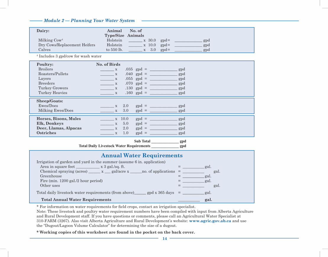
Dairy: Animal No. of Type/Size AnimalsMilking Cow4 Holstein _______ x 30.0 gpd = ______________ gpdDry Cows/Replacement Heifers Holstein _______ x 10.0 gpd = ______________ gpdCalves to 550 lb. _______ x 3.0 gpd = ______________ gpd
4 Includes 3 gpd/cow for wash water
Poultry: No. of BirdsBroilers _______ x .035 gpd = ______________ gpdRoasters/Pullets _______ x .040 gpd = ______________ gpdLayers _______ x .055 gpd = ______________ gpdBreeders _______ x .070 gpd = ______________ gpdTurkey Growers _______ x .130 gpd = ______________ gpdTurkey Heavies _______ x .160 gpd = ______________ gpd
Sheep/Goats: Ewes/Does _______ x 2.0 gpd = ______________ gpdMilking Ewes/Does _______ x 3.0 gpd = ______________ gpd
Horses, Bisons, Mules _______ x 10.0 gpd = ______________ gpd Elk, Donkeys _______ x 5.0 gpd = ______________ gpdDeer, Llamas, Alpacas _______ x 2.0 gpd = ______________ gpdOstriches _______ x 1.0 gpd = ______________ gpd
Sub Total ______________ gpd Total Daily Livestock Water Requirements ______________ gpd
Annual Water RequirementsIrrigation of garden and yard in the summer (assume 6 in. application)
Area in square feet ____________ x 3 gal./sq. ft. = ___________ gal. Chemical spraying (acres) ______ x ___ gal/acre x ______no. of applications = ___________ gal. Greenhouse = ___________ gal. Fire (min. 1200 gal./2 hour period) = ___________ gal. Other uses = ___________ gal.
Total daily livestock water requirements (from above)______ gpd x 365 days = ___________ gal.
Total Annual Water Requirements ___________ gal.
* For information on water requirements for field crops, contact an irrigation specialist. Note: These livestock and poultry water requirement numbers have been compiled with input from Alberta Agriculture and Rural Development staff. If you have questions or comments, please call an Agricultural Water Specialist at 310-FARM (3267). Also visit Alberta Agriculture and Rural Development’s website: www.agric.gov.ab.ca and use the “Dugout/Lagoon Volume Calculator” for determining the size of a dugout.
* Working copies of this worksheet are found in the pocket on the back cover.

Module 2 — Planning Your Water System
15
Worksheet
Sizing of Water Systems
Water System Fixtures Peak Use Rates
Automatic cattle waterers ____ X 2 gpm = ______ gpm (100 head size) Hog nipple waterer ____ X 1 gpm = ______ gpm Poultry fountain ____ X 1 gpm = ______ gpm Yard hydrants ____ X 5 gpm = ______ gpm Household (number of households) ____ X 5-10 gpm = ______ gpm Fire hydrant ____ X 10 gpm = ______ gpm Other ____ X ____gpm = ______ gpm
Note: The minimum design flow rate of the system must exceed the peak use rate of the fixture that uses the largest amount of water.
Note: If the well is not solely capable of providing enough water for your peak use demand, you will need to install additional water storage. The well can be operated without overpumping, and the added water storage provided will ensure water for all your activities during peak demands.
* Working copies of this worksheet are found in the pocket on the back cover.
gpm = gallons per minute
16
Module 2 — Planning Your Water System
* Working copies of this worksheet are found in the pocket on the back cover.
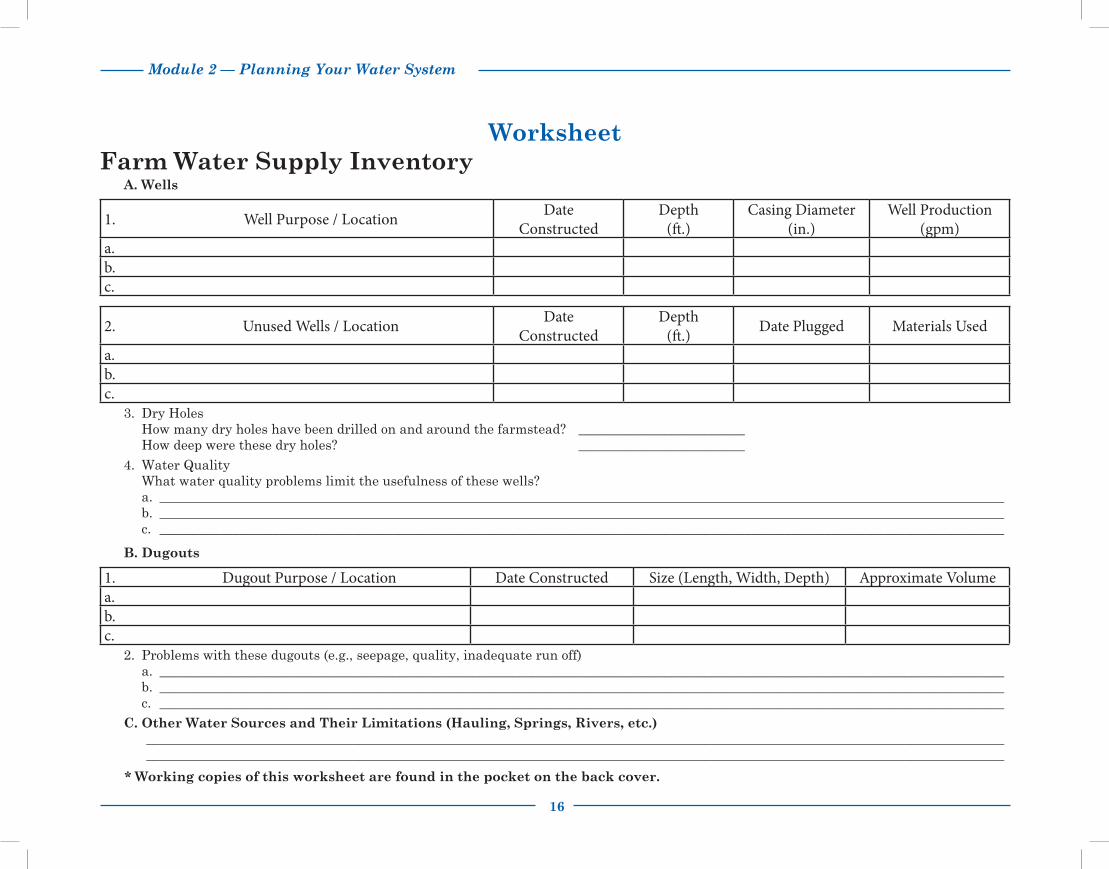
WorksheetFarm Water Supply Inventory
A. Wells
1. Well Purpose / Location DateConstructed
Depth(ft.)
Casing Diameter(in.)
Well Production(gpm)
a.b.c.
2. Unused Wells / Location DateConstructed
Depth(ft.) Date Plugged Materials Used
a.b.c.
3. Dry Holes How many dry holes have been drilled on and around the farmstead? _________________________ How deep were these dry holes? _________________________4. Water Quality What water quality problems limit the usefulness of these wells?
a. _______________________________________________________________________________________________________________________________b. _______________________________________________________________________________________________________________________________c. _______________________________________________________________________________________________________________________________
B. Dugouts
1. Dugout Purpose / Location Date Constructed Size (Length, Width, Depth) Approximate Volumea.b.c.
2. Problems with these dugouts (e.g., seepage, quality, inadequate run off)a. _______________________________________________________________________________________________________________________________b. _______________________________________________________________________________________________________________________________c. _______________________________________________________________________________________________________________________________
C. Other Water Sources and Their Limitations (Hauling, Springs, Rivers, etc.) _________________________________________________________________________________________________________________________________
_________________________________________________________________________________________________________________________________

Module 3 — Design and Construction of Water Wells
17
Design and Construction of Water WellsThe initial investment for a properly designed and constructed well pays off by ensuring:
A reliable and sustainable water supply consistent with your needs and the capability of the aquifer
Good quality water that is free of sediment and contaminants
Increased life expectancy of the well
Reduced operating and maintenance costs
Ease of monitoring well performance.
Although you need to hire a licensed water well contractor to design, drill and construct the well and choose the appropriate materials, it is important for you to know what is going on. You can then work with the contractor to ensure you get the well design you need.
Choosing a Licensed Water Well ContractorChoose a licensed water well contractor who has experience in your area and knows the
local geology. Provincial regulation requires that drilling companies have an approval to drill water wells and their drillers must be certified journeyman water well drillers. A list of approval holders is available through Alberta Environment and Sustainable Resource Development (AESRD). You can also contact the Alberta Water Well Drilling Association for a list of approval holders in your area. Refer to Module 11 “Contacts for More Information”.
Either you or the licensed water well contractor should complete a survey of existing wells in your area. It will provide important information about:
Typical yields and water quality
Which aquifer to tap into
Trends in well design and construction
Prior drilling success rates.
The Groundwater Information Centre at Alberta Environment and Sustainable Resource Development manages the Alberta Water Well Information Database that has records of water wells in Alberta. Copies of these records can be obtained by calling (780) 427-2770 or can be viewed at www.envinfo.gov.ab.ca/GroundWater/.
In some areas of Alberta, regional groundwater assessment studies are also available and may identify aquifer potential and groundwater quality. Also check with neighbours about their experiences with well performance, well maintenance and water quality changes.
For more information see Module 1 "Understanding Groundwater" and Module 2 "Planning Your Water System".
A licensed water well contractor cannot always determine in advance the depth at which an adequate water supply will be found. Neighbouring wells offer some guidance but not a definite assurance.
For more information refer to the Water Wells That Last video (Part I — Planning and Construction).

18
Module 3 — Design and Construction of Water Wells
Other things to consider when choosing a licensed water well contractor are:
Are they approachable? Can you talk comfortably with them about the local geology, their proposed well design and construction and the pumping equipment they recommend?
Do they have a good reputation? Ask for references and check whether previous cllients are happy with their wells.
Are they insured?
Are their prices competitive? The cheapest estimate may not translate into the best well. Be sure to compare cost estimates carefully.
Will they use a written contract or agreement?
Will they provide any guarantee on workmanship and materials?
Will they be responsible for sizing and placement of the pump?
Are they knowledgeable and willing to discuss the regulations that govern water well drilling in Alberta?
Choosing a Well SiteYour choice of well site will affect the safety and performance of your well. As you
examine various sites, remember to consider any future development plans for your farm or acreage such as barns, storage sheds and bulk fuel tanks. You must also consider provincial regulations that dictate well location.
Most contaminants enter the well either through the top or around the outside of the casing. Sewage or other contaminants may percolate down through the upper layers of the ground surface to the aquifer. The following criteria are intended to prevent possible contamination of your well and the aquifer. It is both your and the driller’s responsibility to ensure that:
The well is accessible for cleaning, testing, monitoring, maintenance and repair
The ground surrounding the well is sloped away from the well to prevent any surface run off from collecting or ponding
The well is up-slope and as far as possible from potential contamination sources such as septic systems, barnyards or surface water bodies
The well is not housed in any building other than a bona fide pump house. The pump house must be properly vented to the outside to prevent any build-up of dangerous naturally occurring gases and must house only the well and pumping equipment
The well is not located in a well pit.

Module 3 — Design and Construction of Water Wells
19
Minimum Distance Requirements
Provincial regulations outline minimum distance requirements as follows. Equivalent imperial distances in feet are rounded up to nearest foot. The well must be:
10 m (33 ft.) from a watertight septic tank15 m (50 ft.) from a sub-surface weeping tile effluent disposal field or evaporation
mound or an outdoor pit privy30 m (98 ft.) from a leaching cesspool*50 m (165 ft.) from sewage effluent discharge to the ground surface100 m (329 ft.) from a sewage lagoon
30 m (98 ft.) from pesticide or fertilizer storage 50 m (165 ft.) from above-ground fuel storage tanks
30 m (98 ft.) from manure or composting materials application100 m (329 ft.) from a manure storage facility or manure collection area or
livestock yard100 m (329 ft.) from dead animal burial or composting site
2 m (7 ft.) from overhead power lines if: - the line conductors are insulated or weatherproofed and the line is 750 volts or less
6 m (20 ft.) from overhead power lines if the well: - has a PVC or non-conducting pipe pumping system - has well casing sections no greater than 7 m (23 ft.) in length
12 m (40 ft.) from overhead power lines for all other well constructions
3.25 m (11 ft.) from existing buildings6.1 m (20 ft.) from the outer boundary of any road or public highway50 m (165 ft.) from the outer boundary of a graveyard450 m (1476 ft.) from any area where waste is or may be disposed of at a landfill
*The installation of a leaching cesspool is no longer permitted. It is, however, highly recommended that any newly constructed water well be located at least 30 m (100 ft.) from any existing leaching cesspool. See Module 12 "Other Resources" for the requirements for Alberta Private Sewage Systems.

20
Module 3 — Design and Construction of Water Wells
Well Design ConsiderationsWell design and construction details are determined after a test hole has been completed
and the geological zones have been logged. There are many components to well design the driller must take into account. Decisions will be made about:
Type of well Intended use Well depth Casing material, size and wall thickness Intake design Annular seal Monitoring and preventive maintenance provisions.
Well DepthDuring the test hole drilling, the licensed water well contractor will complete a lithologic
or formation log. Soil and rock samples are taken at various depths and the type of geologic material is recorded. This allows the driller to identify zones with the best potential for water supply. Some drillers also run a geophysical (electric) log in the test hole to further define the geology. This gives them more accurate information about aquifer location.
Generally a well is completed to the bottom of the aquifer. This allows more of the aquifer to be utilized and ensures the highest possible production from the well.
Types of WellsThere are two main types of wells, each distinguished by the diameter of the bore hole.
The two types are bored wells and drilled wells.
Bored wells Bored wells are constructed when low yielding groundwater sources are found relatively
close to the surface, usually under 30 m (100 ft.). Bored wells are constructed using a rotary bucket auger. They are usually completed by perforating the casing (also called cribbing) or using a sand screen with continuous slot openings (see Figure 1, Bored Well).
One advantage of bored wells is the large diameter of the casing, from 45-90 cm (18-36 in.). It provides a water storage reservoir for use during peak demand periods. A disadvantage of utilizing a shallow groundwater aquifer is that it generally relies on annual precipitation for recharge. Water shortages may occur following long dry periods in summer and extended freeze up during winter months. It can also be more susceptible to contamination from surface land-use activities.
Figure 1 Bored Well

Module 3 — Design and Construction of Water Wells
21
Drilled wellsDrilled wells are smaller in diameter, usually ranging from 10-20 cm (4-8 in.), and
completed to much greater depths than bored wells, up to several hundred metres. The producing aquifer is generally less susceptible to pollution from surface sources because of the depth. Also, the water supply tends to be more reliable since it is less affected by seasonal weather patterns.
There are two primary methods of drilling:RotaryCable tool.
Rotary drilled wells are constructed using a drill bit on the end of a rotating drillstem. Drilling fluid or air is circulated down through the drillstem in the hole and back to the surface to remove cuttings. Rotary drilling rigs operate quickly and can reach depths of over 300 m (1000 ft.), with casing diameters of 10-45 cm (4-18 in.).
Cable tool drilled wells are constructed by lifting and dropping a heavy drill bit in the bore hole. The resulting loose material, mixed with water, is removed using a bailer or sand pump. This method, also called percussion drilling, reaches depths up to 300 m (1000 ft.). Well diameters can range from 10-45 cm (4-18 in.). The drilling rate is typically much slower than for a rotary rig, but when aquifers are low yielding, they may be more easily identified using this method.
Materials used in the drilling and construction of water wells must be new and uncontaminated.
Figure 2 Well Completions

22
Module 3 — Design and Construction of Water Wells
There are three types of possible well completions for both drilling methods (see Figure 2, Well Completions):
Surface casing with slotted or perforated linerSand screen with continuous slot openingsSingle string slotted or perforated casing.
Casing Size and TypeDecisions about the diameter and type of well casing are made after the driller considers
the following:
Aquifer characteristics
Hydraulic factors that influence well performance
Drilling method
Well depth
Cost (in discussion with the well owner).
The casing must be large enough to house the pump and allow sufficient clearance for installation and efficient operation.
If a submersible pump is going to be used, the casing must have an inside diameter of at least 10.16 cm (4 in.), by law. It is recommended that the casing be at least one nominal size larger than the outside diameter of the pump. The more space there is between the pump and the casing, the easier it will be to service and repair the pump in the future.
There are two common materials used for casing: steel and plastic. Steel casing is the strongest but is susceptible to corrosion. Plastic casing is becoming more popular because of its resistance to corrosion.
All casing must be new and uncontaminated. Plastic casing must be made of virgin resin, not recycled material.
Intake DesignWater moves from the aquifer into the well through either a screen or slotted or
perforated casing.
Screens are manufactured with regularly shaped and sized openings. They are engineered to allow the maximum amount of water in with minimal entry of formation sediments. Stainless steel screens are the most widely used because they are strong and relatively able to withstand corrosive water. Screens are manufactured with various slot sizes and shapes to match the characteristics of the aquifer.
Provincial regulation provides detailed specifications for casing diameters and wall thicknesses. All casing must meet or exceed standards set by the Canadian Standards Association or the American Society of Testing and Materials (see Module 4” Water Well Drilling Agreements”, Water Well Casing Specifications).

Module 3 — Design and Construction of Water Wells
23
Slotted or perforated casing or liner is made by manually creating openings using a cutting tool or drill. Pre-slotted plastic pipe is also available.
Slot openings and perforations are spaced further apart than screen openings. This reduces the amount of open area to allow water into the well. The openings tend to vary in size and may have rough edges depending on how they were made. This impedes the flow of water into the well and may not be effective in holding back the formation sediments.
The licensed water well contractor examines the cuttings from the borehole and makes a judgement whether to use a screen, or slotted or perforated casing/liner. While a screen is the more expensive alternative, it is necessary if the aquifer is composed of loose material such as fine sand, gravel or soft sandstone. A slotted or perforated casing/liner can be used when the aquifer formation is more consolidated, such as hard sandstone or fractured shale.
After a choice is made between a screen, or slotted or perforated casing/liner other decisions will be made regarding:
Size of slot openings
Total area of screen or perforation that is exposed to the aquifer
Placement of the screen or perforations within the aquifer.
Slot size openingsThe slot openings must be small enough to permit easy entry of water into the well
while keeping out sediment. The slot size chosen will depend on the particle size of the earth materials in the producing aquifer.
Typically a licensed water well contractor will select a slot size that allows 60 percent of the aquifer material to pass through during the well development phase of drilling. The remaining 40 percent, comprising the coarsest materials, will form a natural filter pack around the perforations or screen.
Total open area of screenThe total area of the slot openings is dependent on the length and diameter of the screen.
While the length of the screen is variable, the diameter of the screen is determined by the diameter of the well casing. The yield from a well increases with an increase in screen diameter but not proportionately so.
The amount of open area in the screen or slotted or perforated casing/liner will affect how quickly the water from the aquifer enters the well. A larger amount of open area allows the
Incrustation is a buildup that occurs when dissolved minerals in the groundwater come out of solution and deposit on the screen or casing.
Ensure that the pumping water level in the well never goes below the top of the slot openings or perforations to prevent oxygen exposure to the aquifer which will enhance bacterial growth and result in reduced well yield.

24
Module 3 — Design and Construction of Water Wells
water to enter the well at a slower rate, causing a lower drop in pressure as the water moves into the well. If the water flows too quickly, dissolved minerals in the water will precipitate out of solution and create an incrustation build-up in restricting the flow of groundwater into the well. The pore spaces in the aquifer immediately adjacent to the perforations may also get plugged, restricting the flow even more.
Placement in the aquiferThe screen or perforations on the casing/liner must be placed adjacent to the aquifer. If
improperly placed, the well may produce fine sediment which will plug plumbing fixtures and cause excessive wear on the pump. If the driller uses geophysical logging equipment to accurately identify the boundaries of the aquifer, the exact placement will be easier.
Annular SealSealing the well protects the well’s producing zone from contamination. The diameter
of the borehole is usually slightly larger than the casing being installed. The space between the borehole and the casing is called the annulus of the well or the annular space. It must be sealed to prevent any surface contamination from migrating downward and contaminating the water supply. A properly sealed annulus also prevents any mixing of poor quality water from upper aquifers with water from the producing aquifer of the well (see Figure 3, Annular Seal).
Provincial regulations require the annulus be filled with impervious material such as cement or bentonite. To isolate the producing zone of the well, the annulus should be filled from immediately above the perforated zone to the ground surface.
Well CapA commercially manufactured, vermin-proof well cap is the only type of cap designed
to keep animals, insects and contaminants from entering your well. It comes equipped with rubber gaskets and screened vents to ensure vermin stay out and air can circulate through.
Coverings for large diameter wells must be custom made because of their larger size. Ideally they should be made of steel, or fiberglass or plastic that is stamped for potable water use.
Figure 3 Annular Seal

Module 3 — Design and Construction of Water Wells
25
Well CompletionOnce the well has been drilled and the equipment is in place, there are several
procedures the licensed water well contractor must complete before the well is ready to use. The driller is responsible for:
Developing the well
Disinfecting the well
Conducting a yield test.
Well DevelopmentWell development is the process of removing fine sediment and drilling fluid from the
area immediately surrounding the perforations. This increases the well’s ability to produce water and maximize production from the aquifer.
If the aquifer formation does not naturally have any relatively coarse particles to form a filter, it may be necessary for the driller to install an artificial filter pack. This pack is placed around the screen or perforations so the well can be developed. For example, this procedure is necessary when the aquifer is composed of fine sand and the individual grains are uniform in size.
It is important to match the grain size of the filter pack material with the size of the slot openings of the screen to attain maximum yield from the well. Typically the slot size of the screen is selected so that 85 percent of the artificial pack material will remain outside of the screen after well development.
26
Module 3 — Design and Construction of Water Wells
Yield TestA yield test is important because the information gathered during the test assists the
driller in determining the:
Rate at which to pump the well
Depth at which to place the pump.
Provincial regulations outline the requirement for a minimum yield test to be performed on all new wells. After drilling and developing a well, the licensed water well contractor must remove water from the well for at least 2 hours. If a pump is used to remove the water, then water level measurements can be recorded as the water level draws down during pumping. If the yield test is performed using a bailer or air compressor to remove the water, water level measurements cannot be taken during the water removal portion of the test.
After 2 hours, water removal must be stopped and the recovery of the water level then monitored and recorded. Measurements must be taken at specific time intervals for a 2 hour period or until the water level returns to 90 percent of its original level.
Once the yield test is complete, the driller will decide at what rate the well can be pumped without lowering the water level below the top boundary of the aquifer, the top of the perforations or below the pump intake.
Your pump should have a capacity equal to, or less than, the rate at which the well can supply water for an extended period of time without lowering the water level below the pump intake. That pumping rate is considered the long-term, safe and sustainable pumping rate for the well.
The value of using a pump to perform the yield test is the test will be repeatable. You should periodically conduct a similar yield test to collect new data that can be compared to previous tests. If you notice a decline in well performance you can have your licensed water well contractor back to rehabilitate or repair your well. Keeping a watchful eye on your well will enable you to recognize the symptoms of declining performance before it is too late to economically repair the well.
Disinfecting the WellProvincial regulations require the licensed water well contractor to disinfect new wells
with chlorine. The concentration is calculated on the volume of water that is in the well. The concentration must be at least 200 milligrams of chlorine per litre of water present in the well and must be left in the well for at least 12 hours to ensure any bacteria present are destroyed. Disinfection is done after the pumping equipment is installed and before the well is put into production.
The yield test provides a benchmark of your well's performance. Repeating this test at a later date can be used to assess any changing conditions in well performance and indicate when maintenance is required.

Module 4 — Water Well Drilling Agreements
27
Water Well Drilling AgreementsThis module outlines a checklist of items that you and your licensed water well
contractor should discuss and agree to before starting any drilling. A clear understanding between both parties is crucial so there are no misunderstandings or false expectations. Disagreements can arise between licensed water well contractors and well owners after the well is drilled because they simply did not take the time to thoroughly discuss all aspects of the drilling operation ahead of time.
Water wells are far more than a deep wet holes in the ground. They are an important and significant investment for any household or farm. Well owners should take the time to ensure they understand what they are purchasing. Money spent on high quality well design and construction materials is money well invested. A low cost well may not deliver the quality, quantity or reliability you need.
A Water Well Drilling Agreement covers the topics you should discuss with your licensed water well contractor before any work begins. A blank copy of an example agreement is included at the back of this module and in the pocket on the back cover. Many contractors have their own version of a Water Well Drilling Agreement.
Water Well Drilling Agreement ExampleThis agreement is designed to prevent misunderstandings between the well owner and
licensed water well contractor. It benefits both parties and can establish costs for materials and services.
IdentificationItems 1-4 identify the parties involved in the agreement.
1. Well owner _____________________________________________________________________
Address ________________________________________________________________________
2 Licensed water well contractor __________________________________________________
Address ________________________________________________________________________
Licensed water well contractor approval no. _______________________________________
3. Land location of well Qtr________ Sec ________ Twp_________ Rge_________ W of_________ Meridian Lot_____________________ Block_____________________ Plan___________________
4. Proposed starting date __________________________________________________________
Proposed completion date _______________________________________________________
For more information refer to the Water Wells That Last video (Part I — Planning and Construction).
John Q. DoeAnywhere, Alberta
Peters Water Well ServicesAnywhere, Alberta
NE 36 17 7 4
June 21, 2012June 25, 2012

28
Module 4 — Water Well Drilling Agreements
Water Requirements5. Proposed well use: Household__________ Livestock__________ Irrigation__________
The well use should be specified as being for household, livestock, irrigation or a combination. Municipal and industrial wells are usually covered by a detailed contract.
6. Desired water quality
Finding groundwater with suitable water quality is important for all water uses. A licensed water well contractor can use a field testing kit to get a rough estimate of some parameters such as iron, hardness, pH and total dissolved solids, but only the tests done in a laboratory are really reliable.
Laboratories use the Guidelines for Canadian Drinking Water Quality to assess water quality. If testing shows some of the parameters are higher than these guidelines, water treatment equipment may be necessary.
7. Desired yield_____________L/s (gpm) Min. acceptable yield_____________L/s (gpm)
The desired yield is the flow rate of water, in gallons per minute (gpm), from an individual well. To calculate the desired yield, refer to the worksheet "Average Daily and Annual Water Requirements" in Module 2, "Planning Your Water System". Using this worksheet, calculate your daily and peak water use requirements. In some areas the desired yield is simply not available because of slow yielding aquifers. In such cases, the desired yield should be expressed as the normal yield for the area. A certain minimum yield should be established so if the well produces less than this minimum, it is not considered economically feasible to develop as a water well.
8. Groundwater supply options based on existing records _____________________________ _______________________________________________________________________________
The licensed water well contractor or well owner should review groundwater information on local wells to determine potential target aquifers and appropriate well design considerations. Information is available from the Groundwater Information Centre. See Module12,"Other Resources".
Well Construction9. Maximum desired depth_______________ m (ft.)
A maximum desired depth should be established. Factors affecting this include the known depth of productive aquifers, and the water quality at the various depths. Also personal finances will be a factor.
Consolidated Bedrock, Paskapoo Formation Sandstone units — 30 to 60 m (100 to 200 ft.)
X
0.4 (5) 0.1 (1)
65 (210)
You should discuss the purpose of any new well being drilled with your licensed water well contractor. If the well is going to be used for a non-household purpose it must be constructed in a manner that will allow it to be licensed.

Module 4 — Water Well Drilling Agreements
29
10. Type of drilling _________________________________________________________________
11. Diameter of hole ________________________________________________________________
The type of drilling equipment, aquifer composition, yield required and depth determine the type of well produced. Rotary drilled and cable tool drilled wells are typically100-200 mm (4-8 in.) in diameter; bored wells range in diameter from 45-90cm (12-36 in.). The water well drilling industry is required by law to construct wells with casings 102mm (4in.) or more to accommodate submersible pumps.
12. Flowing well control ____________________________________________________________
In cases where a flowing well is anticipated, provision must be made to equip the well with a flow control device that allows the flow to be shut off completely and to prevent freezing.
13. Well connection _________________________________________________________________
Where the connection of the pumping equipment to the well casing is made below the ground surface, a pitless adaptor is required under the Water (Ministerial) Regulation. Well pits are no longer permitted. If a jet pump is being used, a pump house that houses only the well and the pumping equipment is allowed.
14. Formation logging procedure ____________________________________________________
Logging the geological formations during drilling provides key information about aquifer location and quality. This information is especially important to accurately place well screens. There can be several types of formation logging.
Descriptive logging records the material encountered as drilling proceeds (lithology).
Electric logging, or E logging, verifies and supplements descriptive logging. It can only be performed in an uncased hole that is filled with drilling fluid. Basically it reveals the character of the material and relative quality of water in the formation. A limited number of licensed water well contractors in Alberta possess this equipment.
Gamma-ray logging can be performed in cased holes without drilling fluid and reveals the character of the material present. Very few licensed water well contractors in Alberta have this equipment. A combination of descriptive logging and electric or gamma-ray logging provides very accurate information about the formations through which the well is constructed.
Pitless Adaptor
N / A
Rotary
158 mm (6 1/4" ) and 124 mm (4 7/8" )

30
Module 4 — Water Well Drilling Agreements
15. Annular or casing seal _________________________________________________________All wells must be constructed to prevent contaminated surface water from entering
groundwater aquifers through the annulus (or space) between the outside of the well casing and the borehole. The annulus must be filled from immediately above the producing zone up to ground surface. The method of sealing is dependent on the type of rig the driller operates and the design of the well.
16. Artificial sand pack _____________________________________________________________
The grain size distribution of the aquifer affects the efficiency of the screen during development. If the aquifer has a relatively uniform fine grain size, a well cannot be effectively developed without the installation of an artificial sand pack. This "pack" provides a natural filter which holds back the finer aquifer materials.
17. Well Development Method
Backwashing__________ Jetting__________ Surging__________
Heavy pumping__________ Bailing__________
By regulation, the licensed water well contractor is responsible for ensuring a well is completed in a manner that ensures no damage will be incurred to the pumping system, plumbing or fixtures due to sediment in the water. If a newly constructed well produces sediment, it is usually because the licensed water well contractor did not properly develop it. Different types of well completion require different development techniques. In the rare case where a well cannot be adequately developed to produce sediment-free water, a sediment filter could be installed in the water distribution system. However, this alternative should be used only when it is evident that sufficient development of the well has been done, and the landowner is in agreement.
Material
18. Casing material ________________________________________________________________
Inside diameter____________ wt. per m (ft.)___________ wall thickness___________
See Water Well Casing Specifications, page 33.
BentoniteGood well design, construction and material selection is necessary to reduce the effects of natural corrosion, biofouling and incrustation.
Plastic Schedule 80* PVC * Steel Protector casing at Surface
0.375127 mm (5")
X

Module 4 — Water Well Drilling Agreements
31
19. Well cover _________________. Distance from top of casing to ground surface__________________
Minimum requirement is 20cm (8") above ground surface or 60cm (2") above the highest flood record unless a water tight cover is used. A water-tight, vented vermin-proof cap is ideal. For large diameter wells, a tight-fitting, vented cover should be specified.
The well cap should be removable or be designed to allow access to a dip tube for ease of monitoring the water level.
20. Liner material __________________________________________________________________
Inside diameter____________ wt. per m(ft.)__________ wall thickness____________See Water Well Casing and Specifications, page 33. Plastic PVC or ABS casing lasts
indefinitely because it does not rust like metal casing, however it must be protected at the ground surface with metal casing.
21. Screen Manufacturer ____________________________________________________________
Length ________________________________________________________________________
Material _______________________________________________________________________
Nominal diameter ______________________________________________________________
Wells completed in unconsolidated aquifers, such as sand or gravel, should be screened. The length of screen required depends on the volume of water to be pumped and the ability of the aquifer to transmit water.
Yield Testing22. Yield testing duration (hours) ____________________________________________________
The licensed water well contractor should conduct a yield test following completion of the well. It serves as a benchmark for monitoring future well performance. The test should include the following information:
a) non-pumping (static) water level
b) water removal rate in gpm(L/s)
c) depth to the pumping water level as determined over a period of time at a constant pumping rate(drawdown)
d) the length of time the well is pumped
e) the recovery of the water level over a 2 hour period or until 90 percent recovery of the non-pumping water level is reached.
23. Pump Type ________________ Size ____________________
The purpose of measuring the well's yield is to gather enough information to determine what pumping equipment will best ensure adequate water pressure and prevent damage to the well by over-pumping. Not all licensed water well contractors include pump installation as part of their business. Be sure to select your pump contractor carefully and provide them with the yield test data collected by your driller.
It is important to get a good pump yield test on the well when it is constructed. This provides a base condition to which the productivity of the well can be compared as it "ages."
300 mm (12")6” well cap
Plastic Schedule 40 PVC0.237
ABC Screen Co.
Sub 0.5 HP
102 mm (4")
Minimum: 2 hour water removal and 2 hour recovery

32
Module 4 — Water Well Drilling Agreements
Disinfection
24. Disinfection ____________________________________________________________________
After the well is completed and pumping equipment is installed you should disinfect the water in the well with at least 200mg/L of chlorine and left in the well for a minimum of 12 hours. Use Table 1, Amount of Chlorine for a Chlorine Concentration of 200PPM ,and the example in Step 3 on page 51 to calculate the amount of chlorine for 200 ppm.
25. Well head finishing _____________________________________________________________
Well head finishing includes the clean up of mud and aquifer debris and removal of material scraps.
Costs
26.Test holes per metre (foot) _________________________________________________________
27.Reaming per metre (foot) __________________________________________________________
28.Drilling/boring per metre (foot) ____________________________________________________
29.Casing per metre (foot) ____________________________________________________________
30.Liner per metre (foot) _____________________________________________________________
31.Screen ___________________________________________________________________________
32.Sandpack ________________________________________________________________________
33.Development _____________________________________________________________________
34.Labor per hour ___________________________________________________________________
35.Water testing ____________________________________________________________________
36.Reclamation of unused well _______________________________________________________
37.Total Costs ______________________________________________________________________
38.Payment schedule ________________________________________________________________
Guarantee
39.
Workmanship and materials should be guaranteed for a specific period of time.
Provincial regulation requires that a water well be completed to ensure no damage will be incurred to the pumping system, plumbing or fixtures due to sediment in the water.
Well and pumping equipment to be disinfected
Driller to remove all surplus materials and equipment on site.
Contact local licensed water well contractors for cost estimates in your area.
While the licensed water well contractor is on site, you may want to get an estimate to plug any unused wells on your property to protect water quality in your new well. For more information, see Module 9 "Plugging Abandoned Wells".

Module 4 — Water Well Drilling Agreements
33
Plastic Well Casing—Required Thickness for ABS or PVC
Outside PipeDiameter in. (mm)
Casing Schedule(SCH) Number
Minimum WallThickness in. (mm)
4.5 (114.3)4.95 (125.7)
SDR21SCH 40
0.214 (5.43)0.260 (6.60)
5Nominal(127.0)5.56 (141.2)
SCH 80 0.397 (10.1)
6 (152.4)6.625 (168.3)6.625 (168.3)
WellCasingSCH 40SCH 80
0.390 (9.9)0.432 (11.0)0.280 (7.1)
8.625 (219.7)8.625 (219.7)
SCH 40SCH 80
0.322 (8.2)0.5 (12.7)
10.75 (273.1)10.75 (273.1)
SCH 40SCH 80
0.365 (9.2)0.593 (15.1)
Non-Plastic Well Casing—Required Thickness
Type of Well Casing Minimum Casing Thickness
Metal well casing 0.188 in.(4.78mm)
Metal liner casing 0.156 in. (3.96mm)
Cement-like casing
* for 24in.(60.96 cm) casing or less
* for casings larger than 24in.
* 2.5in.(6.35cm)
* 2.5in.plus 1in.forevery additional foot of well diameter
Corrugated and galvanized steel casing
16gauge
Water Well Casing Specifications
Materials All well casing material must meet or exceed the specifications set for that material and purpose by the Canadian Standards Association or the American Society for Testing and Materials.

34
Module 4 — Water Well Drilling Agreements

Module 4 — Water Well Drilling Agreements
35
Water Well Drilling Agreement Form
Identification1. Well owner _______________________________________________________________________________________________________________________
Address __________________________________________________________________________________________________________________________
2 Licensed water well contractor ____________________________________________________________________________________________________
Address __________________________________________________________________________________________________________________________
Licensed water well contractor approval no.___________
3. Land location of well: Qtr_______ Sec_______ Twp_______ Rge_______ W of_____Meridian Lot_______ Block_______ Plan_______
4. Proposed starting date ____________________________________________________________________________________________________________
Proposed completion date _________________________________________________________________________________________________________
Water Requirements5. Proposed well use: Household______________ Livestock_____________ Irrigation______________
6. Desired water quality On-site tests:
total dissolved solids_______________________parts/million iron______________________________________parts/million
hardness_________________________________parts/million pH_______________________________________parts/million
7. Desired yield_____________L/s (gpm) Min. acceptable yield_____________L/s (gpm)
8. Groundwater supply options based on existing records _______________________________________________________________________________
Well Construction9. Maximum desired depth_______________ m (ft.)
10. Type of drilling ___________________________________________________________________________________________________________________
11. Diameter of hole __________________________________________________________________________________________________________________
12. Flowing well control ______________________________________________________________________________________________________________
13. Well connection ___________________________________________________________________________________________________________________
14. Formation logging procedure ______________________________________________________________________________________________________

36
Module 4 — Water Well Drilling Agreements
15. Annular or casing seal ____________________________________________________________________________________________________________
16. Artificial sand pack _______________________________________________________________________________________________________________
17. Well development method: Backwashing__________ Jetting_________ Surging__________ Heavy pumping__________ Bailing__________
Material18. Casing material __________________________________________________________________________________________________________________
Inside diameter__________ wt. per m(ft.)__________ wall thickness__________
19. Well cover __________________________ Distance from top of casing to ground ________________________________________________________
20. Liner material ____________________________________________________________________________________________________________________
Inside diameter__________ wt.per m(ft.)__________ wall thickness__________
21. Screen
Manufacturer ____________________________________________ Material _____________________________________________________________
Length __________________________________________________ Nominal diameter ____________________________________________________
Yield Testing22. Yield testing duration (hours) ______________________________________________________________________________________________________
23. Pump type _________________________ Size _______________________________________________________________________________________
Disinfection24. Disinfection ______________________________________________ 25. Well head finishing _______________________________________________
Costs26. Test holes per metre (foot) _________________________________ 32. Sand pack _______________________________________________________
27. Reaming per metre (foot) __________________________________ 33. Development _____________________________________________________
28. Drilling/boring per metre (foot) _____________________________ 34. Labor per hour ___________________________________________________
29. Casing per metre (foot) ____________________________________ 35. Water testing ____________________________________________________
30. Liner per metre (foot) _____________________________________ 36. Reclamation of unused well _______________________________________
31. Screen ___________________________________________________
Total37. Total Costs _______________________________________________ 38. Payment schedule ________________________________________________
Guarantee39. Guarantee _______________________________________________________________________________________________________________________
* Working copies are included in the pocket on the back cover.

Module 5 — Monitoring and Maintenance of Your Water Well
37
Monitoring and Maintenance of Your Water Well
Preserving the water source on your farm or acreage is as vital as preserving the quality of your soil.
When we think of factors that limit farm production, what come to mind are land base, finances, time and energy. What doesn’t always come to mind is how necessary water supplies are. Imagine having to reduce the size of a cattle herd or not being able to water your horses because of a lack of water. Water is key to our quality of life as well. Waiting an hour to take a bath or not having enough water to serve two bathrooms would be a change for many families.
Proper care and maintenance of your water source are key to protecting your water supply. An effective monitoring program will identify changes in water levels and water quality before they become serious problems. Just like a vehicle needs an oil change, tune up and inflated tires to run properly, your well needs to be monitored, checked and cared for. Regular, systematic inspections and treatment of problems will help increase the life of your well. A licensed water well contractor may be required at times.
In this module you will learn several methods of monitoring your well. A worksheet where you can record your own information is included at the back.
The first step in preventative maintenance of your well is taking some simple measurements. Two measurements that you need to take on a routine basis are:
Water level measurements
Water quality measurements.
Water Level MeasurementsTaking water level measurements on a regular basis will tell you whether water levels
have changed significantly. In turn, this can help you spot the following problems:
Pumping the well at a greater rate than it is designed for (stressing the well by over-pumping)
Pumping the well at a greater rate than the aquifer is capable of producing (depleting the aquifer)
A plugged screen (or slotted casing) can diminish the well's efficiency and production rate
Reducing groundwater recharge due to land clearing and surface water drainage.
In some areas of Alberta, up to one-third of the new wells licensed are considered marginal or poor for either water quantity or quality. Monitoring and maintaining these wells is key to maximizing the water available and preserving the quality.
For more information refer to the Water Wells That Last video (Part II — Managing and Maintaining).
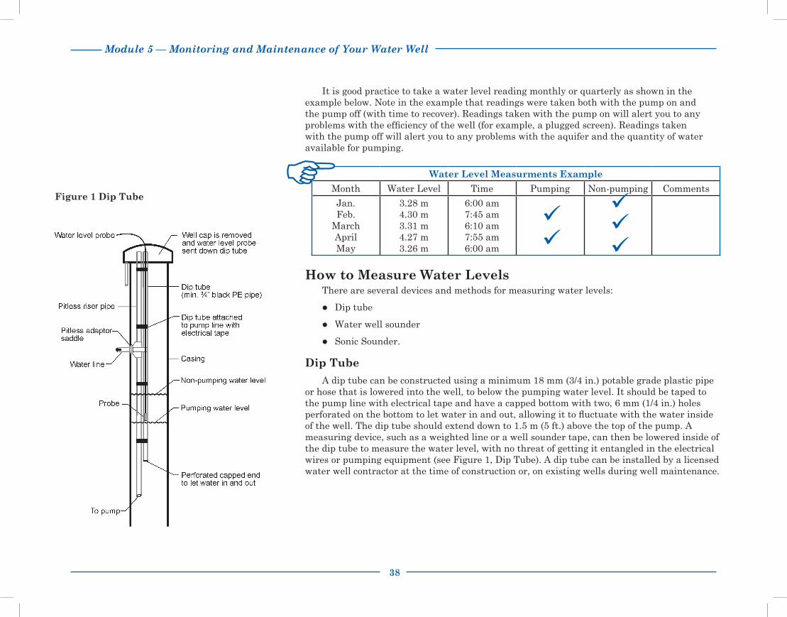
38
Module 5 — Monitoring and Maintenance of Your Water Well
It is good practice to take a water level reading monthly or quarterly as shown in the example below. Note in the example that readings were taken both with the pump on and the pump off (with time to recover). Readings taken with the pump on will alert you to any problems with the efficiency of the well (for example, a plugged screen). Readings taken with the pump off will alert you to any problems with the aquifer and the quantity of water available for pumping.
Water Level Measurments Example
Month Water Level Time Pumping Non-pumping Comments
Jan. Feb.
March April May
3.28 m4.30 m3.31 m4.27 m3.26 m
6:00 am7:45 am6:10 am7:55 am6:00 am
How to Measure Water LevelsThere are several devices and methods for measuring water levels:
Dip tube
Water well sounder
Sonic Sounder.
Dip Tube
A dip tube can be constructed using a minimum 18 mm (3/4 in.) potable grade plastic pipe or hose that is lowered into the well, to below the pumping water level. It should be taped to the pump line with electrical tape and have a capped bottom with two, 6 mm (1/4 in.) holes perforated on the bottom to let water in and out, allowing it to fluctuate with the water inside of the well. The dip tube should extend down to 1.5 m (5 ft.) above the top of the pump. A measuring device, such as a weighted line or a well sounder tape, can then be lowered inside of the dip tube to measure the water level, with no threat of getting it entangled in the electrical wires or pumping equipment (see Figure 1, Dip Tube). A dip tube can be installed by a licensed water well contractor at the time of construction or, on existing wells during well maintenance.
Figure 1 Dip Tube

Module 5 — Monitoring and Maintenance of Your Water Well
39
Water Well Sounder
A convenient method for measuring the water level is to use a water well sounder (also called a water tape). You can purchase one from various suppliers in the province. Although it is relatively expensive, it is a good investment. It’s an accurate and convenient way to take water level measurements.
Sonic Sounder Method
The sonic well sounder is convenient because it does not need to be lowered down the well. It is simple to use for most well constructions and only requires that the well cap be removed. This instrument sends a pulse of sound down the well and records the time required for the sound to echo back from the water surface, using time to calculate the distance to the water level. It is non–invasive and easy to operate but may be more expensive and less accurate than a well sounder.
Interpreting Water LevelsOnce you have an accurate method for measuring water levels, you need to be able to
interpret two types of water levels — non-pumping (static) and pumping.
Non-pumping Water Levels
The non-pumping water level is recorded after the water level in the well has been allowed to fully recover and before the pump is turned on. A good time to take a non-pumping reading is first thing in the morning before there has been any water use.
After you have recorded several measurements over a period of time, you can determine if the non-pumping water level in the well has changed significantly. Some change will occur due to seasonal fluctuations. For example, in shallow wells, water levels are usually highest in June or July and gradually decline in late September or October and throughout the winter.
Water well sounders and sonic sounders may be available for sale or rent from water well drilling companies and water well industry suppliers. Tape sounders should be sanitized before and after each use.
Deep wells of 60-90m (200-300 ft) do not experience seasonal fluctuations like shallow wells.

40
Module 5 — Monitoring and Maintenance of Your Water Well
Let’s look at some examples and how the results might be interpreted.
Example 1The table below shows four non-pumping water level readings.
Month Time Water Level* Pumping Non-pumping
January 1, 2012 April 3, 2012
August 1, 2012December 1, 2012
6:00 am5:45 am5:30 am6:10 am
3.28 m3.27 m3.30 m3.29 m
*Distance from the top of the casing to water level.
Interpretation: It would appear that there have been no significant changes in the water level over the year so no action is required. The aquifer seems able to supply water to the well at the rate you have been pumping.
Example 2You look back over your records for the past year and note the following
non-pumping water level readings.
Month Time Water Level Pumping Non-pumping
February 1, 2011April 1, 2011June 1, 2011
August 1, 2011October 1, 2011
December 2, 2011February 1, 2012
6:05 am5:45 am6:00 am6:05 am5:50 am6:00 am5:55 am
10.35 m12.48 m11.53 m16.31 m20.22 m26.57 m30.34 m
Interpretation: In this case, you should be concerned. The water level has dropped 20 m over the past year. To address the drop in water level, reduce the amount of water you draw from the well. You can do this by reducing the pumping rate and cutting back on the amount of water use.
Take another measurement in a month to see if the water level is recovering. If you find that the water level begins to rise again, you have been over-pumping your aquifer, producing more water from the well than the aquifer can supply. To prevent your well from going dry, you will need to pump your well at a reduced rate.
If the non-pumping water level suddenly drops after remaining steady for many years, it may be a result of increased use from nearby wells that are completed in the same aquifer as your well.

Module 5 — Monitoring and Maintenance of Your Water Well
41
If the water level does not recover, you will need to:
Further reduce water use
Look for other possible water sources.
Pumping Water Level
Record the pumping water level while the pump is operating. If you take several readings over time, you will have data that can help you assess the efficiency of the well. When you take pumping water level measurements, you need to be consistent about when the measurements are taken. For example, you might take the measurement after the pump has been on for 2 hours. Being consistent allows you to compare the readings (see Figure 3, Pumping Water Level Drawdown).
Figure 3 Pumping Water Level Drawdown

42
Module 5 — Monitoring and Maintenance of Your Water Well
See Module 7 "Troubleshooting Water Well Problems" for more information on well problems.
Even when the pumping water level remains relatively steady, you need to do regular annual maintenance, including shock chlorination, to control bacteria buildup. If you allow a well to deteriorate for too long, it may not be possible to restore its original capacity.
If the well yield declines, yet the non-pumping water level remains constant, the well may need to be serviced by a licensed water well contractor. If your well is capable of producing more water than you require, you may not notice a decrease in well yield unless you are routinely monitoring your water levels.
A good time to take a pumping water level reading is during the day when the pump is pumping, for example, at noon. By then there has been significant water use. Taking the reading at the same time of day will give you comparable water levels, unless water use varies considerably between seasons.
Now let’s look at the significance of some pumping water level measurements.
Example 3In the table below, six readings were taken after the pump was on for 2 hours.
Month Time Water Level Pumping Non-pumping
February 2, 2012March 1, 2012May 1, 2012June 1, 2012
September 2, 2012December 2, 2012
11:30 am11:15 am11:35 am11:20 am11:25 am11:15 am
6.67 m5.23 m6.34 m5.35 m6.29 m7.02 m
Interpretation: Since the levels are relatively constant, there does not seem to be a problem with the efficiency of the well and no action is required.
Example 4You look back over your records and find that, although the original non-pumping
water level has remained constant, the pumping water level has declined.
Month Time Water Level Pumping Non-pumping
February 1, 2011April 2, 2011June 1, 2011
August 3, 2011October 1, 2011
December 2, 2011February 1, 2012
11:30 am11:20 am11:35 am11:45 am11:30 am11:40 am11:50 am
20.15 m21.56 m26.26 m28.37 m33.45 m37.20 m40.16 m
Interpretation: The screen (or slotted casing) may be plugged with sand, bacterial growth or mineral incrustation. When this happens, the efficiency of the well is diminished and the production rate (yield) drops.
To correct the problem, hire a licensed water well contractor to determine exactly what is causing the reduced efficiency of the well. The screen (or slotted casing) may need to be surged to remove sediment or in some cases may need to be replaced. You may need to shock chlorinate the well to reduce bacteria or acidize it to remove incrustation on the casing or screen.

Module 5 — Monitoring and Maintenance of Your Water Well
43
Water Quality MeasurementsNoting changes in water quality is an effective way to monitor your water well. Aquifer
contamination, problems with a well's structure, or lack of routine maintenance could each lead to a change in water quality.
Use the following checklist as a starting point to determine if a problem exists.
Checklist to Determine a Water Quality Problem
Unpleasant odour or taste
Red discoloration on plumbing fixtures and fabric
Cloudy, dirty water
Soap curd on dishes and fabrics
Scale in pipes and water heater
Salty alkali taste
Some changes in water quality are not detected by changes in taste, smell or appearance. For this reason it is important to sample and analyze your water on a routine basis.
Bacteriological AnalysisBacteriological analysis determines the total coliform and faecal coliform bacteria in the
water. Coliform bacteria are usually present in soil and surface water. Faecal coliform are present in animal and human waste. Both are indicator organisms for the potential presence of pathogenic (disease causing) bacteria.
A bacteriological analysis does not test for iron bacteria or sulphate-reducing bacteria which are commonly found in well water. A bacteriological analysis should be done annually.
Chemical AnalysisA routine chemical analysis tests for the most common chemical parameters found in
water, such as iron, sodium, sulfates, nitrates and nitrites. In some cases, you may need to request testing for additional parameters when a regional health concern is identified (such as arsenic or fluoride).
A routine chemical analysis should be done every two to five years.
A bacteriological analysis can be done for minimal cost through your local health unit. This should be done annually.

44
Module 5 — Monitoring and Maintenance of Your Water Well
Non-routine TestingNon-routine testing is necessary when unusual situations occur. Unexplained illnesses,
obvious contamination situations such as pesticide or hydrocarbon spills, or flooding are examples. Occurrences on neighboring properties may also provide reason for non-routine testing. Since specialized testing is expensive, get advice on which parameters are worth testing.
SamplingHow you collect a water sample is as important as the analysis. Proper sampling bottles
and procedures are required and can be obtained through your local health unit or private laboratory. Samples not in the proper sampling bottle will not be accepted for testing.
Important considerations are:
Length of time well is pumped prior to sample taken
How sample is stored
Length of time for sample to be delivered to a laboratory.
Collect the sample as close to the well head as possible to avoid any effect the water treatment or distribution system may have on the sample. If you want to assess the effectiveness of your treatment system, you will have to take an additional sample.
Interpreting Results Whenever an analysis is done, you will receive a written copy of the results. Keep this
information in the front pocket of this manual with your other important papers. It helps to create a history of your well to use for comparison should the water quality ever change.
You can also use the analyses to help you decide whether or not any water treatment equipment is needed to improve your water quality.
Local health units are responsible for identifying whether water is fit for human consumption. The Canadian Drinking Water Quality Guidelines published by Health Canada are used to establish when the parameters exceed established maximum acceptable concentrations.
Tests for chemical contaminants such as pesticides, hydrocarbons, etc., require special arrangements.
Check ahead of time with your local health unit or private laboratory for proper sampling procedures and drop off times.
The “Rural Water Quality Information Tool” provides For information on interpreting water quality analysis results. See Module 12 "Other Resources".

Module 5 — Monitoring and Maintenance of Your Water Well
45
WorksheetWater Well Monitoring Log
Year_________ Well No. _____ Qtr_____ Sec_____ Twp_____ Rge_____ W of_____Meridian Lot_____ Blk_____ Plan____
Month / Day Time Water Level Comments (quality, presence of sediment, yield problems)
Pumping Non-pumping
January _______
February _______
March _______
April _______
May _______
June _______
July _______
August _______
September _______
October _______
November _______
December _______
* At the end of the year, review the chart for any water level trends.
* Working copies are included in the pocket on the back cover.

46
Module 5 — Monitoring and Maintenance of Your Water Well

Module 6 — Shock Chlorination
47
Shock ChlorinationShock chlorination is a relatively inexpensive and straightforward procedure used to
control bacteria in water wells. Many types of bacteria can contaminate wells, but the most common are iron-related (IRB) and sulfate-reducing bacteria (SRB). Although not a cause of health problems in humans, these nuisance bacteria may coat the inside of the well casing, water piping and pumping equipment, creating problems such as:
Reduced well yield
Restricted water flow in distribution lines
Staining of plumbing fixtures and laundry
Plugging of water treatment equipment
“Rotten egg” odour.
Increased corrosion of the metal parts of the well and distribution system
Wells can also be contaminated with harmful bacteria such as fecal coliforms or E. coli. Shock chlorination is the most effective method to eliminate them. Bacteria may be introduced during drilling of a well or when pumps are removed for repair and laid on the ground. However, IRBs and SRBs (as well as other bacteria) can exist naturally in groundwater.
A well creates a direct path for oxygen to travel into the ground where it would not normally exist accelerating the growth of bacteria that require oxygen. When a well is pumped, the water flowing in will also bring in nutrients that enhance bacterial growth.
Note: All iron staining problems are not necessarily caused by iron-related bacteria. The iron naturally present in the water can be the cause. See Module 12 "Other Resources" for more information.
For more information refer to the Water Wells That Last video (Part III — Shock Chlorination).
Water wells provide ideal conditions for IRBs. To thrive, IRBs require 0.5-4 mg/L of dissolved oxygen, as little as 0.01 mg/L dissolved iron and a temperature range of 5 to 15°C. Some IRBs use dissolved iron in the water as a food source.
Well maintenance is essential to ensure that a well will last.

48
Module 6 — Shock Chlorination
Signs of Nuisance Bacteria There are a number of signs that indicate the presence of iron-related, sulfate-reducing
and other slime-producing bacteria. They include:Slime growth Rotten egg odor Increased staining.
Slime GrowthThe easiest way to check a well and water system for nuisance bacteria is to examine
the inside surface of the toilet flush tank. If you feel a greasy slime or growth, these are probably present.
Rotten Egg OdourSulfate-reducing bacteria can cause a rotten egg odour in water. Iron-related bacteria
aggravate the problem by creating an environment that encourages the growth of SRBs in the well. SRBs prefer to live underneath the slime layer that the IRBs form because they thrive in low oxygen environments. SRBs produce hydrogen sulfide gas as a by-product, resulting in a “rotten egg” or sulfur odour in the water and may produce small amounts of acid that can corrode the well casing and pumping equipment.
Increased Staining ProblemsIron-related bacteria can concentrate iron in water sources with low iron content. It can
create a staining problem where one never existed before or make an iron staining problem worse as time goes by.
Use the following checklist to determine if you have an iron-related or sulfate-reducing bacteria problem. The first three are very specific problems related to these bacteria. The last two problems can be signs of other problems as well.
Checklist to Determine an Iron-Related or Sulfate-Reducing Bacteria Problem
Greasy slime on inside surface of toilet flush tank
Increased red staining of plumbing fixtures and laundry
Sulfur odour
Reduced well yield
Restricted water flow

Module 6 — Shock Chlorination
49
Shock Chlorination MethodShock chlorination is used to control iron-related and sulfate-reducing bacteria and to
eliminate faecal coliform or E. coli bacteria in a water system. To be effective, shock chlorination should be done on a regular basis at least once or twice per year as part of a routine well maintenance program. Start the treatments early in the life of your well. Shock chlorination will disinfect the following:
The entire well depth The formation around the bottom of the well
The pressure system Some water treatment equipment
The distribution system.
To accomplish this, a large volume of chlorinated water is siphoned down the well to displace all the water in the well and some of the water in the formation surrounding the well.
Effectiveness of Shock ChlorinationWith shock chlorination, the entire system (from the water-bearing formation, through the
well-bore and the distribution system) is exposed to water which has a concentration of chlorine strong enough to kill iron-related and sulfate reducing bacteria (see Figure 1, Water System). Bacteria collect in the pore spaces of the formation and on the casing or screened surface of the well. To be effective, you need to calculate the correct volumes of chlorine and water required to reach and disinfect the entire cased section of the well and adjacent water-bearing formation.
The procedure described on the following pages does not completely eliminate nuisance bacteria from the water system, but it will hold it in check. To control the iron-related bacteria, you will have to repeat the treatment on a regular basis, likely each spring and fall as a regular maintenance procedure. If your well has never been shock chlorinated or has not been done for some time, it may be necessary to contact a licensed water well contractor about other products and methods for control of bacteria.
Adding chlorine increases the pH of the water. An increase in pH reduces the ability of chlorine to disinfect or kill bacteria. Your licensed water well contractor may have specialized chemicals designed to reduce pH and optimize disinfection.
Shock chlorination will not be effective on wells that have been seldom or never been treated. These poorly maintained wells likely require the services of an experienced licensed water well contractor who has the necessary equipment and products to effectively and safely clean and restore the well water quality and production. Sometimes these wells can be restored to near their original water quality and production capacity after the well driller uses scrubbing equipment and applies an acid treatment to remove the heavy layers of bacterial slime on the well casing prior to disinfecting with a chlorine solution. After a thorough cleaning it may be possible to return to regular shock chlorination treatments to control bacteria buildup and its related problems.
Before you shock chlorinate, consult your water treatment equipment supplier to ensure the appropriate steps are taken to protect your treatment equipment.
Be aware that chlorinating old, unmaintained wells may uncover existing holes in steel casing and speed up inevitable well failure.

50
Module 6 — Shock Chlorination
Shock Chlorination Procedure for Drilled Wells
A modified procedure is also provided for large diameter wells.
Caution: If your well is low yielding or tends to pump any silt or sand, you must be very careful using the following procedure because over-pumping may damage the well. When pumping out the chlorinated solution, monitor the water discharge for sediment.
Store sufficient water to meet farm and family needs for 8 to 48 hours.
Pump the recommended amount of water (see Table 1, Amount of Chlorine Required to Obtain a Chlorine Concentration of 200 PPM) into clean storage. A clean tank, used only for storing potable or chlorinated water should be used. The recommended amount of water to use is twice the volume of water present in the well casing*. To measure how much water is in the casing, subtract the non-pumping water level from the total depth of the well. See the example below.
Imperial Example
The drilling record indicates the casing is 200 ft. in length and the non-pumping ("static") water level is 100 ft. The length of casing that is holding water in it is 100 ft. (200-100). If your casing is 6 in. in diameter you need to pump 2.4 gal. of water for every foot of water in the casing, into your storage container. Since you have 100 ft. of water in the casing, you will pump 2.4 gal./ft. x 100 ft. = 240 gal. of water into storage.
Using Table 1, calculate how much water you need to pump into clean storage.
Casing diameter_________ needs_________gal./ft. x __________ ft. = ____ ______ gal.
Step 1
Step 2
*Large cisterns should be bypassed and treated separately. If the water must travel through a long or large diameter pipeline, or large pressure tanks, an extra volume of chlorinated solution should be used. Consult with a licensed water well drilling contractor or a water specialist.

Module 6 — Shock Chlorination
51
Sodium Hypochlorite (5¼% & 12%, liquid form) has a shelf life. Purchase new stock and check for an expiry date. Buy only as much as you need for the procedure. 12% industrial sodium hypochlorite and 70% high test hypochlorite are available from:
• Water treatment suppliers
• Licensed water well contractors
• Swimming pool maintenance suppliers
• Dairy equipment suppliers
• Some hardware stores.
Table 1 Amount of Chlorine Required for a Chlorine Concentration of 200 PPM
3 See modified procedure for large diameter wells on page 53.
4 To reduce the chlorine concentrations to 50 ppm, divide the above chlorine amounts by 4.
1 Domestic chlorine bleach should not have additives or perfumes.
2 Since a dry chemical is being used, it should be mixed with water to form a chlorine solution before placing it in the well.
Calculate the amount of chlorine that is required, as shown in Table 1. Mix the chlorine with the previously measured water to obtain a 200 ppm chlorine solution.
Calculating Amount of Chlorine Example
If your casing is 6 in. and you are using 12% industrial sodium hypochlorite, you will require 0.018 L per ft. of water in the casing. If you have 100 ft. of water in the casing, you will use 0.018 L x 100 ft. = 1.8 L of 12% chlorine.
Using Table 1, calculate the amount of chlorine you will need for your well.
Casing diameter_______ Chlorine strength_______L needed per 1 ft. of water_______ x _______ ft. of water in casing = _______ L of chlorine.
Step 3
If your well is located in a pit, proper safety precautions need to be taken during the chlorination procedure. It is best to use a licensed water well contractor who has the proper equipment and experience to do the job safely. Well pits are no longer legal to construct.
Caution: Chlorine is corrosive and can even be deadly.
Casing Diameter
Volume of Water Needed
5 1/4%1Domestic Chlorine Bleach
12% IndustrialSodium
Hypochlorite
270% High Test
Hypochlorite
Water needed per 1 ft. (30 cm)of water in the casing
L neededper 1 ft. (30 cm) of water
L neededper 1 ft. (30 cm) of water
Dry weight2 per 1 ft. (30 cm) of water
(in) (mm) (gal.) (L) (L) (L) (g)
4 (100) 1.1 5.0 .019 .008 1.44
6 (150) 2.4 10.9 .042 .018 3.12
8 (200) 4.2 19.1 .072 .032 5.46
24 (600)3 extra 200 gal. extra 1000 L .340 .148 25.40
36 (900)3 extra 200 gal. extra 1000 L .76 .34 57.20
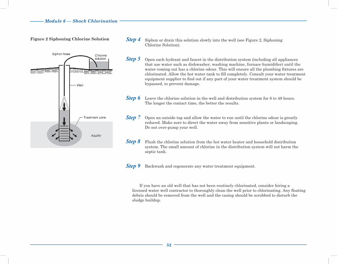
52
Module 6 — Shock Chlorination
Siphon or drain this solution slowly into the well (see Figure 2, Siphoning Chlorine Solution).
Open each hydrant and faucet in the distribution system (including all appliances that use water such as dishwasher, washing machine, furnace humidifier) until the water coming out has a chlorine odour. This will ensure all the plumbing fixtures are chlorinated. Allow the hot water tank to fill completely. Consult your water treatment equipment supplier to find out if any part of your water treatment system should be bypassed, to prevent damage.
Leave the chlorine solution in the well and distribution system for 8 to 48 hours. The longer the contact time, the better the results.
Open an outside tap and allow the water to run until the chlorine odour is greatly reduced. Make sure to direct the water away from sensitive plants or landscaping. Do not over-pump your well.
Flush the chlorine solution from the hot water heater and household distribution system. The small amount of chlorine in the distribution system will not harm the septic tank.
Backwash and regenerate any water treatment equipment.
If you have an old well that has not been routinely chlorinated, consider hiring a licensed water well contractor to thoroughly clean the well prior to chlorinating. Any floating debris should be removed from the well and the casing should be scrubbed to disturb the sludge buildup.
Step 9
Step 8
Step 7
Step 6
Step 5
Step 4Figure 2 Siphoning Chlorine Solution
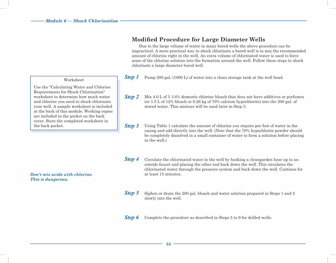
Module 6 — Shock Chlorination
53
Modified Procedure for Large Diameter WellsDue to the large volume of water in many bored wells the above procedure can be
impractical. A more practical way to shock chlorinate a bored well is to mix the recommended amount of chlorine right in the well. An extra volume of chlorinated water is used to force some of the chlorine solution into the formation around the well. Follow these steps to shock chlorinate a large diameter bored well.
Pump 200 gal. (1000 L) of water into a clean storage tank at the well head.
Mix 4.0 L of 5 1/4% domestic chlorine bleach that does not have additives or perfumes (or 1.5 L of 12% bleach or 0.26 kg of 70% calcium hypochlorite) into the 200 gal. of stored water. This mixture will be used later in Step 5.
Using Table 1 calculate the amount of chlorine you require per foot of water in the casing and add directly into the well. (Note that the 70% hypochlorite powder should be completely dissolved in a small container of water to form a solution before placing in the well.)
Circulate the chlorinated water in the well by hooking a cleangarden hose up to an outside faucet and placing the other end back down the well. This circulates the chlorinated water through the pressure system and back down the well. Continue for at least 15 minutes.
Siphon or drain the 200 gal. bleach and water solution prepared in Steps 1 and 2 slowly into the well.
Complete the procedure as described in Steps 5 to 9 for drilled wells.
Step 1
Step 2
Step 3
Step 4
Step 5
Step 6
Worksheet
Use the "Calculating Water and Chlorine Requirements for Shock Chlorination" worksheet to determine how much water and chlorine you need to shock chlorinate your well. A sample worksheet is included at the back of this module. Working copies are included in the pocket on the back cover. Store the completed worksheet in the back pocket.
Don't mix acids with chlorine. This is dangerous.

54
Module 6 — Shock Chlorination
WorksheetCalculating Water and Chlorine Requirements (200 PPM) for Shock Chlorination
Complete the following table using your own figures to determine how much water and chlorine you need to shock chlorinate your well.
Casing Diameter Volume ofWater Needed
5 1/4% 1DomesticChlorine Bleach
12% Industrial Sodium Hypochlorite
270% High Test CalciumHypochlorite
(in) (mm) Imperial gal. needed per1 ft. of water in the casing L per 1 ft. (30 cm) of water L per 1 ft. (30 cm) of water Dry weight2 per 1 ft.
(30 cm) of water
4 (100) _____ft. x 1.1 gal. = _____ _____ft. x 0.019 L = _____ _____ft. x 0.008 L = _____ _____ft. x 1.44 g = ______
6 (150) _____ft. x 2.4 gal. = _____ _____ft. x 0.042 L = _____ _____ft. x 0.018 L = _____ _____ft. x 3.12 g = ______
8 (200) _____ft. x 4.2 gal. = _____ _____ft. x 0.072 L = _____ _____ft. x 0.032 L = _____ _____ft. x 5.46 g = ______
24 (600)3 extra 200 gal. _____ft. x 0.340 L = _____ _____ft. x 0.148 L = _____ _____ft. x 25.40 g = _____
36 (900)3 extra 200 gal. _____ft. x 0.760 L = _____ _____ft. x 0.34 L = ______ _____ft. x 57.20 g = _____
3 See modified procedure for large diameter wells on page 53.1 Domestic chlorine bleach should not have additives or perfumes.
2 Since a dry chemical is being used, it should be mixed with water to form a chlorine solution prior to placing it in the well.
* Working copies are included in the pocket on the back cover.
Module 7 — Troubleshooting Water Well Problems
55
Troubleshooting Water Well Problems
Water well problems result from many causes including equipment failure, depletion of the aquifer, corrosive qualities of the water and improper well design and construction. Correctly identifying the cause enables you to select appropriate treatment or maintenance to fix the problem rather than abandon the well. This troubleshooting module is designed to help you recognize the symptoms of the problem, identify the cause and select the appropriate course of action. Technical assistance from licensed water well contractors or groundwater consultants may be valuable. See Module 11 "Contacts for More Information".
For more information refer to the Water Wells That Last video series (Part II — Managing and Maintaining).
Causes of Well ProblemsThere are several basic causes of well problems.
● Improper well design and construction● Incomplete well development● Borehole stability problems● Incrustation build-up● Biofouling● Corrosion● Aquifer problems● Over-pumping.
The first two causes relate to the expertise and performance of the licensed water well contractor. Borehole stability problems, incrustation, corrosion and aquifer problems are related to characteristics of the aquifer. The last cause, overpumping, is caused by well users.
Exercise
List any problems or symptoms with your well.
___________________________________________________________________________________
___________________________________________________________________________________
___________________________________________________________________________________

56
Module 7 — Troubleshooting Water Well Problems
Improper Well Design and ConstructionWhen designing a well, the licensed water well contractor must match the type of well
construction with the characteristics of the producing aquifer. Decisions must be made about:
● Perforated well casing/liner vs. well screen (see Figure 1, Perforated Well Liner and Well Screen)
● Slot size of well screen
● Placement of well screen or perforated liner
● Size and amount of sand pack around the well screen (if required)
● Location of the pump in the well.
If poor choices are made, you may experience problems with sediment in your water or reduced well yield. Provincial regulations require that a well must be completed to ensure no damage will be incurred to the pumping system, plumbing or fixtures due to sediment in the water. For more information on well design and construction, see Module 3 "Design and Construction of Water Wells."
Incomplete Well DevelopmentDuring drilling, mud and bore hole cuttings can partially plug the aquifer. This material
must be fully removed by the licensed water well contractor to allow water to freely enter the well. This procedure is part of well development. If the well has not been fully developed, you may experience problems with sediment in your water or low well yield.
Borehole Stability ProblemsBorehole stability problems can result from damaged casing and screens, borehole
wall collapse, corrosion or excessive water velocities into the well. High water velocity can cause formation particles, like sand, to flow into the well, causing eventual collapse of the borehole wall.
It is essential that the proper materials be selected and installed to avoid such problems. A combination of poor materials, improperly placed screens and a poor well seal make it uneconomical to maintain and restore such a well. Often the most cost effective solution is to drill a new well that is properly designed and constructed.
Figure 1 Perforated Well Liner and Well Screen
Module 7 — Troubleshooting Water Well Problems
57
Mineral IncrustationMineral incrustation is a common problem in some shallow water table type aquifers
where there is an abundance of dissolved minerals including calcium, magnesium and iron, as well as iron bacteria. When water is pumped from the well, changes in pressure and temperature occur. This creates ideal conditions for minerals to precipitate or settle out, causing scale formation on the casing, liner and screens.
A combination of good preventive maintenance and good management practices can minimize the effect of incrustation. Management practices that reduce water pumping rates can reduce the effects of mineral incrustation. A strategy of reduced pumping rate with longer pumping intervals helps prevent incrustation of screens and perforated liners.
BiofoulingInstalling and pumping a well increases the level of oxygen and nutrients in the well and
in the surrounding aquifer. Bacteria, such as iron bacteria, may thrive under these conditions. They can form a gel-like slime or biofilm that captures chemicals, minerals and other particles such as sand, clays and silts. Minerals, such as iron, oxidize and get trapped in the biofilm. "Biofouling" occurs where biofilm accumulations are sufficient to reduce water flow. This can mean reduced well yield and water quality.
CorrosionChemical substances found in water can eat away or corrode metal well casings. To avoid
corrosion, the licensed water well contractor must choose a casing material that is suitable for the water supply. For example, licensed water well contractors usually select plastic casing liners and stainless steel well screens for corrosive water. Sulfate-reducing bacteria can also cause corrosion. Shock chlorination can keep these bacteria in check.
Although incrustation or scale formation occurs mostly in the screen or slotted casing, it can also affect the formation around the well.
Shock chlorination is effective as a regular maintenance technique to kill bacteria and limit its ability to create biofilm. However, shock chlorination is not effective at penetrating biofilm. If biofilm buildup is suspected, the introduction of appropriate chemicals and physical agitation is required to remove the biological plugging material.

58
Module 7 — Troubleshooting Water Well Problems
Over-pumpingA well is over-pumped if water is withdrawn at a faster rate than the well was designed for or the aquifer is able to produce. Over-pumping is the most common well problem that leads to premature well failure. Over-pumping not only depletes the groundwater aquifer (or source), but it rapidly increases the rate of corrosion, incrustation and biofouling related problems. Over-pumping also increases the rate of sediment particles moving toward the well, causing plugging of the perforated area where water flows into the well. It can also cause the aquifer to settle and compact which further restricts water flow to the well.
Dissolved Gas in WaterThe presence of gas in water wells is common in Alberta. Oxygen, carbon dioxide, nitrogen, methane and hydrogen sulphide may occur naturally in some of the aquifers in which water wells are drilled (e.g. coal seams, fractured shales and sandstones). When gas is present, it is held in groundwater under pressure. Pumping water wells completed in such aquifers can reduce the pressure, releasing the gas. Sometimes gas in groundwater can affect the operation of your well. Even if gas is present, it may still be possible to use your well in a safe manner. Refer to the troubleshooting guide on page 63 for methods of controlling dissolved gas in water.
Aquifer ProblemsWhile most well problems are related to the construction, development or operation of the
well, the formation can also be a source of problems.
Reduced aquifer yield can be caused by lack of recharge. For example, the amount of water withdrawn can exceed the recharge from rain and snow melt. This is referred to as "mining the aquifer". Sometimes the decline in water level is seasonal. Typically water levels are higher in spring and lower in the fall. Extended dry periods can also impact water levels, especially in shallow water table type aquifers.
Checking the water level in your well is an important maintenance procedure. You will be able to identify water level trends and identify well problems or aquifer depletion before the problem becomes serious.
Now go back to the exercise at the start of this module. Try to identify possible causes for each problem you identified.
For more information on checking water levels, see Module 5 "Monitoring and Maintenance of Your Water Well".
If you are pumping water at a rate close to the well's capacity, excessive pump cycling can increase the problem of biofouling.
Module 7 — Troubleshooting Water Well Problems
59
Troubleshooting GuideThere are four common symptoms associated with most water well problems:
● Reduced well yield
● Sediment in the water
● Change in water quality
● Dissolved gas in the water.
The guide on the next four pages refers to these four symptoms. To use the guide, find the section that identifies the symptom you are experiencing. Look down the left hand column for possible causes of the problem. Beside each cause is listed some indicators you can check for and ways to correct the problem.
Be aware that in many cases the well problem can be the result of a combination of causes and therefore correction may be a combination of actions as well.

60
Module 7 — Troubleshooting Water Well Problems
Symptom #1 — Reduced Well Yield
Possible causes: What to check for: How to correct:
Pump and/or water system Low pump production in spite of normal water level in well. Leak in system; worn pump impeller.
Have a licensed water well contractor or plumber check the pump and water system.
Biofilm build-up in well casing, well screen or pump intake.
Slime build-up on household plumbing fixtures and livestock waterers. Inspect pump and use down-hole camera to check for slime build-up.
Shock chlorinate the well and water system as required - usually once or twice a year. See Module 6 "Shock Chlorination".
Mineral scale (incrustation) build-up on perforated well casing, well or pump screen.
Scale formation on plumbing fixtures and livestock waterers. Inspect pump. Use down- hole video camera to check for mineral build-up. Calculate the Ryznar Stability Indexto determine the water's incrustinq potential.
Once the type of mineral scale has been identified, the well should be cleaned by a licensed water well treatment specialist. Treatment could include both physical aqitation and chemical/acid treatment.
Sediment plugging on outside of perforated casing or screen.
Sediment in water, followed by a sudden decline in yield.
Have a licensed water well contractor redevelop the well.
Collapse of well casing or borehole due to age of well.
Sediment in water. Compare current depth of well with original records. A collapsed well will show a shallower depth than the original well.
Recondition the well. If repair is not economical, plug the well and redrill. • See Module 9 "Plugging Abandoned Wells”.
Neighbouring well interference. Check for significant drop in water levels in nearby wells. Contact Alberta Environment and Sustainable Development to determine if groundwater use in the area has increased.
Identify other nearby wells located in the same aquifer. Reduce pumping rates as required.
Aquifer depletion- rate of withdrawal exceeds rate of recharge- periods of drought can temporarily deplete shallow groundwater zones
Compare current non-pumping static water level with the level at the time of well construction. A lower level confirms aquifer depletion. Contact Alberta Environment and Sustainable Development to see if water levels are declininq.
Reduce the water use. Install additional storage to meet peak water requirements. Drill a deeper well or one that taps into another aquifer.

Module 7 — Troubleshooting Water Well Problems
61
Symptom #2 — Sediment in Water
Possible causes: What to check for: How to correct:
Improper well design or construction. Sediment appears in water shortly after well completion. Well production does not improve with pumping.
Have the licensed water well contractor return to assess and repair the construction problem.
Insufficient well development after construction.
Sediment appears shortly after well completion. Well production may improve with pumping.
Have the licensed water well contractor return to redevelop the well.
Continuous over-pumping of well. Sediment appears in water. Compare current discharge rate of well with the recommended rate at the time of construction.
If the current flow rate is higher than the recommended rate, install a flow restrictor on pump. If required, install additional storage to meet peak water requirements.
Corrosion of well casing, liner or screen causing holes.
Sudden appearance of sediment in water when there was no previous problem. May be coupled with a change in water quality. Calculate the Ryznar Stability Index to determine the water's corrosion potential.
Consult a licensed water well contractor. Depending on the well construction, repair or replace well using alternate construction materials. Plug old well. See Module 9 "Plugging Abandoned Wells”.
Failure of the annular or casing seal. Sudden appearance of sediment, coupled with a change in water quality. Test water quality regularly and investigate when quality changes occur
Consult a licensed water well contractor. It may be possible to re-establish the seal. If repair is not economical, plug the well and redrill. See Module 9 "Plugging Abandoned Wells”.

62
Module 7 — Troubleshooting Water Well Problems
Symptom #3 — Change in Water Quality
Possible causes: What to check for: How to correct:
Corrosion of well casing, liner or screen, causing holes. Holes can allow water of undesirable quality to enter the well.
Change in water quality, may be coupled with sudden appearance of sediment in water. Calculate the Ryznar Stability Index to determine the water's corrosion potential.
Consult a licensed water well contractor. Depending on the well construction, repair or replace well using alternate construction materials. Plug old well. See Module 9 “Plugging Abandoned Wells”.
Failure of the annulus or casing seal. Sudden appearance of sediment, coupled with a change in water quality. Test water quality regularly and investigate when quality changes occur.
Consult a licensed water well contractor. It may be possible to re-establish the seal. If repair is not economical, plug the well and redrill. See Module 9 "Plugging Abandoned Wells".
Iron-related bacteria or sulfate-reducing bacteria (biofouling).
Change in water quality such as colour, odour (e.g., rotten egg) or taste. Check inside of toilet tank for slime build-up and inspectpump.
Shock chlorinate the well. For more information on shock chlorination, see Module 6 "Shock Chlorination".
Contamination sources. Changes in water quality such as colour, odour or taste. Compare results from regular water analyses for changes.*
Identify and remove contamination source. Continue to monitor water quality through regular water testing.
* In many cases, variations in water quality will not result in observable changes in odour, taste or colour. For instance, in situations where nitrate levels are increasing, there may be no apparent change in the odour, taste or colour of the water.

Module 7 — Troubleshooting Water Well Problems
63
Symptom #4 — Dissolved Gas in the Water
Possible causes: What to check for: How to correct:
Dissolved gases in well water including:- carbon dioxide- methane
Spurting household water taps.
Milky color to the water which lasts only a few seconds.
Cautions:1. Carbon dioxide is an asphyxiant2. Methane can be flammable and explosive.
For low concentrations of gas:• Install an air volume release valve on the
pressure tank, if the tank does not have an air bladder. Also ensure the tank is properly vented outside of building.
• Spray water from the well into a sealed storage tank that is properly vented to the outside.
For higher concentrations of gas:• Determine the depth that the gas is
entering the well.• If possible, lower the pump intake to below
where the gas is entering. A licensed water well contractor could install a plastic gas sleeve over the pump intake so the gas will be forced out of the water as it enters the intake. The gas will accumulate at the top of the well, so properly vent the well head so the gas is directed to the outside.
Over-pumping the well. Malfunctioning pump (gas-locking). Refer to your pump manual to troubleshoot for your pumping system.
Compare the rate at which you are pumping the well with the rate recommended by the driller on the drilling report.
Have a licensed water well contractor or plumber check the pump and pressure system equipment for malfunction. Make sure any new pumping equipment is sized correctly to meet the production capability of the well. Reduce well pumping rate if necessary and install additional storage to meet peak water requirements if required.

64
Module 7 — Troubleshooting Water Well Problems

Module 8 — Protecting Your Well From Contamination
65
Protecting Your Well From Contamination
Probably the most important asset on your property is your water well. Unfortunately it is often misunderstood and taken for granted. This lack of understanding increases the risk of contamination to the groundwater. Contamination can be a health risk to both people and livestock. Groundwater is an important resource that needs to be protected.
Contamination of groundwater is hard to detect in early stages. By the time the problem is obvious, there is little that can be done to remove the contaminant from the system. It can take a very long time for contaminants to be flushed out, often decades or longer. Prevention of pollution is the only effective approach.
Often the biggest contamination threats are things in your own backyard. The following are examples of potential problems and some ways to prevent them.
Poor Well Construction The fastest way to contaminate groundwater is through a well. A well provides a
direct path for contamination to travel from the surface to the aquifer.
An inadequate well casing or annular seal may allow surface water or contaminated groundwater to seep along the outside of the casing and enter your well (see Figure 1, Annulus or Casing Seal).
Unsecure, missing or inadequate well caps provide a direct path for vermin, insects and other organisms to contaminate the well.
Locating a well in close proximity to possible sources of contamination could have a negative effect on the water quality
Multi-aquifer well completion allows mixing of water from several aquifers which may have significantly different water qualities (see Figure 2, Multi-Aquifer Well Completion).
Prevention: The best defense is to hire a licensed water well contractor. They must obtain an approval that authorizes them to drill water wells in the province. To obtain this approval, they must have a certified journeymen water well driller to operate each drilling rig. Standards for drilling, construction and reclamation of wells are outlined in the Water (Ministerial) Regulation of the Water Act.
For more information refer to the Water Wells That Last video series (Part II — Managing and Maintaining).

66
Module 8 — Protecting Your Well From Contamination
Figure 2 Multi-Aquifer Well CompletionFigure 1 Annular or Casing Seal
Old Wells Old unused wells that are poorly constructed or have corroded steel casing can lead to
contamination of an aquifer. Nearby wells, completed in that aquifer, may eventually become contaminated.
Prevention: Old unused wells must be properly plugged. See Module 9 "Plugging Abandoned Wells."

Module 8 — Protecting Your Well From Contamination
67
Well Pits Well pits provide a place for contaminated surface water or shallow groundwater
to collect. When this water sits in the pit, it can contaminate the aquifer by seeping around the outside of the well casing or flowing into the well. This type of construction also makes it very susceptible to contamination by small animals and insects (see Figure 3, Well Pit). For this reason well pits are no longer allowed.
Well pits can also be a deadly safety hazard. With changes in atmospheric pressure, air from within the well casing can displace "normal" air in the well pit. Well gases or low oxygen content resulted in human deaths, even recently. People entering the well pit can be asphyxiated. Wells located in basements and pump houses can also be susceptible to this problem.
Methane gas build-up can cause explosions.
Prevention: Pitless adaptors provide a safe, sanitary and frost-free connection from the pumping system to the water well (see Figure 4, Pitless Adaptor). For more information, see the publication Pitless Adaptors, listed in Module 12 "Other Resources".
Figure 4 Pitless Adaptor
Provincial regulation now prohibits the construction of well pits.
Prevention: If a well pit exists, do not enter it alone and without ventilating it aggressively beforehand. It is best to have well pits removed by an experienced contractor with certification in working in confined spaces.
Figure 3 Well Pit

68
Module 8 — Protecting Your Well From Contamination
Farm Water Hydrants Installed in a Well or Well Pit
Hydrants are designed to prevent freezing by draining water back down the well when they are shut off. This means the contents of the stand pipe and hose will syphon back into the well. If the hose is directly connected to the water in a tank, this water will also be syphoned down the well (see Figure 5, Farm Water Hydrant). The contents of stock tanks, sprayers, etc. are examples of possible contaminants.
Prevention: Always maintain an air gap between the end of a hose and the water surface, or install a backflow prevention device.
Always disconnect hoses from the hydrants when not in use.
Prevention: Never locate a hydrant in a well casing or well pit.
Poor Sewage Systems Shallow groundwater can be contaminated by poorly designed, installed or operating
sewage systems (see Figure 6, Poor Sewage Systems). Cesspools constructed over the years have been specifically identified as a greater risk.
Prevention: The construction of cesspools is no longer permitted.
Prevention: In Alberta, only contractors who are certified by the Alberta Onsite Wastewater Management Association, and who hold a valid, annual Private Sewage Disposal System (PSDS) Ticket from the Province of Alberta, are eligible to obtain permits and install private sewage treatment systems. See Module 3 "Design and Construction of Water Wells" for minimum distance requirements, and Module 11 "Contacts for More Information," Alberta Onsite Wastewater Management Association, for requirements.
Figure 5 Farm Water Hydrant
Figure 6 Poor Sewage Systems
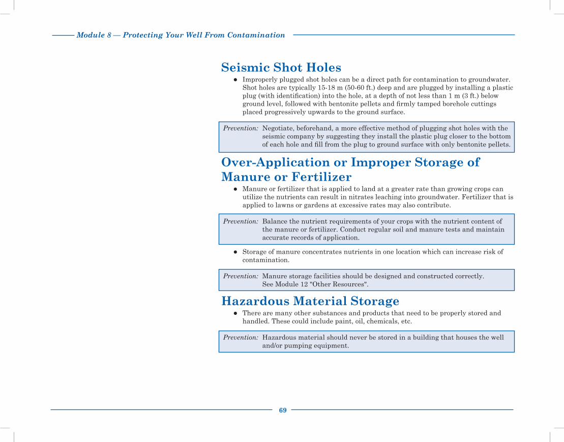
Module 8 — Protecting Your Well From Contamination
69
Seismic Shot HolesImproperly plugged shot holes can be a direct path for contamination to groundwater.
Shot holes are typically 15-18 m (50-60 ft.) deep and are plugged by installing a plastic plug (with identification) into the hole, at a depth of not less than 1 m (3 ft.) below ground level, followed with bentonite pellets and firmly tamped borehole cuttings placed progressively upwards to the ground surface.
Prevention: Negotiate, beforehand, a more effective method of plugging shot holes with the seismic company by suggesting they install the plastic plug closer to the bottom of each hole and fill from the plug to ground surface with only bentonite pellets.
Over-Application or Improper Storage of Manure or Fertilizer
Manure or fertilizer that is applied to land at a greater rate than growing crops can utilize the nutrients can result in nitrates leaching into groundwater. Fertilizer that is applied to lawns or gardens at excessive rates may also contribute.
Prevention: Balance the nutrient requirements of your crops with the nutrient content of the manure or fertilizer. Conduct regular soil and manure tests and maintain accurate records of application.
Storage of manure concentrates nutrients in one location which can increase risk of contamination.
Prevention: Manure storage facilities should be designed and constructed correctly. See Module 12 "Other Resources".
Hazardous Material StorageThere are many other substances and products that need to be properly stored and
handled. These could include paint, oil, chemicals, etc.
Prevention: Hazardous material should never be stored in a building that houses the well and/or pumping equipment.

70
Module 8 — Protecting Your Well From Contamination
Fuel Storage TanksLeaking fuel can contaminate your water supply with hydrocarbons by penetrating
water distribution lines or seeping directly into your aquifer.
Prevention: Design and construct a proper refueling area. Monitor your fuel tanks for leakage. Practice proper refueling procedures to avoid spills. Be prepared to clean up spills. See Module 12 "Other Resources", Farm Fuel Storage and Handling.
Pesticide Contamination The most common reason pesticide contamination of wells occurs is poor pesticide
handling in the area around the well.
The highest contamination risk involving field application is when the following factors all come together: • persistent pesticides • high water table • highly permeable soils • high pesticide application rate.
Prevention: Never fill sprayer tanks near a well. Always use a nurse tank to haul clean water to the field for pesticide mixing.
Store pesticides properly, away from the well. Properly rinse and dispose of empty pesticide containers.
Contamination During MaintenanceWells can easily become contaminated with bacteria when pumps, piping and
equipment are laid on the ground prior to placement into the well or during maintenance procedures.
Prevention: Pumps, piping and equipment should be thoroughly disinfected before going back into the well and the well should be shock chlorinated.
A better understanding of groundwater and wells is key to preventing contamination problems. Use these preventative techniques to ensure that the wells on your farm provide a safe water supply for years to come.
Fuel tanks must be located at least 50 m (164 ft.) from water wells. Buried fuel tanks are a major environmental liability and should be avoided.

Module 8 — Protecting Your Well From Contamination
71

72
Module 8 — Protecting Your Well From Contamination

Module 9 — Plugging Abandoned Wells
73
Plugging Abandoned WellsWhen a well is no longer being used or maintained for future use, it is considered
abandoned. Abandoned wells pose a serious threat to the preservation of groundwater quality. They are also a serious safety hazard for children and animals.
There are approximately 59,000 farmsteads in Alberta and most of these have at least one well. In addition there are a great number of non-farming rural residents that rely on water wells. The exact number of abandoned wells in Alberta is unknown but is estimated to be in the tens of thousands. Plugging an abandoned well prevents:
Downward movement of water in the well or well annulus
Surface contamination from reaching aquifers
Intermixing of water between aquifers of different water quality
Serious accidents from happening.
Unfortunately, groundwater contamination and its effects are usually not recognized until groundwater quality is seriously affected and nearby wells have been contaminated. Surface contaminants can enter a well several ways:
Directly through the surface opening if the cap is loose, cracked or missing
Through unsealed spaces along the outside of the casing (see Figure 1, Well Contamination).
When the steel casing of an abandoned well starts to corrode, holes will develop. When this takes place, surface contaminants or poor quality water from shallow aquifers may migrate into the deeper aquifers of nearby operating wells (see Figure 2, Contamination From an Abandoned Well).
For more information refer to the Water Wells That Last video (Part II — Managing and Maintaining).
Wells that are no longer being used should be plugged. They are a serious public safety and environmental hazard.
Figure 1 Well Contamination
Figure 2 Contamination From an Abandoned Well

74
Module 9 — Plugging Abandoned Wells
Who is Responsible?In Alberta, responsibility for plugging a water well is defined by legislation. The well
owner is responsible for plugging the well when:
The well is no longer being used as a water supply
The well is in a poor state of repair and the pumping equipment has been removed or cannot be repaired or replaced
The well produces water that is unsuitable for drinking.
The licensed water well contractor is legally responsible for immediately plugging a well when it is not completed due to construction problems or inadequate yield. Before you sign a contract with a driller, ask questions about what materials are going to be used to plug the well and associated costs.
It is generally best to hire a licensed water well contractor to complete the plugging of your well. This person has the expertise and equipment to do a proper job. Unless you use the right plugging materials and have them properly placed in the well, you will end up with a poorly sealed well that will continue to allow contaminants to enter into the groundwater. When a replacement well is drilled, your old well should be immediately plugged.
Process of Plugging a WellThere are several steps to take before actually plugging the well. Some steps you will be
able to do yourself and others you may want to consult with, or hire, a licensed water well contractor to complete.
PreparationTo know exactly how much plugging material is needed, measure the total depth and
diameter of the well, plus the non-pumping water level (the depth to the standing water in the well). If possible, compare these measurements to the information on the drilling report from when the well was originally constructed. The only time you should even consider plugging a well yourself is when the well is open to its original depth.
Ideally the casing should be removed from the well before the plugging process begins. Often only the liner casing is removed and the surface casing is left intact because it is more difficult to remove and it could separate down hole. The older the well, the more difficult it will be to successfully remove the casing. If the casing is left in place, it should be perforated, particularly if there is evidence of water movement in the annulus of the well. Any casing left in place must be cut off 0.5 m (20 in.) below ground surface after the well is plugged.
For information on how to take a non- pumping water level measurement, see Module 5 "Monitoring Your Water Well".

Module 9 — Plugging Abandoned Wells
75
MaterialsMaterials that are used to plug a well must be uncontaminated and impervious.
They must prevent any movement of water. See the chart below for acceptable and unacceptable materials.
Acceptable Materials Unacceptable Materials
• grout - neat cement (cement mixed with water) - sand cement (cement, sand and water)
• concrete (cement, sand and aggregate mixed with water)
• manufactured high yield bentonite products
• clean, uncontaminated clay (for large diameter wells)
sand
gravel
drilling mud or fluid
High yield bentonite is a special type of clay that swells when wet to provide a very effective impervious seal. It comes in a powder that when mixed with water produces a slurry that can be pumped into the well. It is also manufactured in pellet or granular form that is designed to pour into the well. This type of bentonite when mixed with water will actually swell to about eight times its original size and will form a water-tight plug.
It is important to understand that bentonite cannot be used as a plugging material in some situations. When the chloride level in the well water is greater than 4000 mg/L, or the calcium level is greater than 700 mg/L, bentonite will not swell properly, so then it is best to use a cement grout.
Large diameter or bored wells pose special problems because of their size and the volume of material required to fill them. A lower cost alternative for the plugging material is clean, uncontaminated clay that can be shovelled into the well until it is filled. This must be done carefully, however, to ensure the clay reaches the bottom of the well and seals off all empty space. The cribbing must be cut off below ground surface and the well should be topped up with high yield bentonite to make a water-tight seal.
Cement grout and concrete may shrink after setting so may not create as good a seal as bentonite.
Sand and gravel are not acceptable materials. They are not impervious materials because water can easily move through them.

76
Module 9 — Plugging Abandoned Wells
MethodAside from choosing the appropriate plugging material, the method of placing material
into the well is most critical. Regulation requires that the plugging material must be introduced from the bottom of the well and placed progressively upward to ground surface.
If the plugging material is cement grout, concrete or bentonite slurry, special equipment is needed. The material must be placed into the well through a tremie pipe that is usually about 3 in. in diameter. At all times this pipe must be kept below the surface of the plugging material to prevent it from diluting or separating. It is recommended that you hire a licensed water well contractor when a slurry is chosen as the plugging material because they will have the proper equipment and experience to do the job correctly.
When bentonite pellets are chosen for the plugging material, they can be poured into the well from the ground surface. These pellets have a weight material added to help them sink to the bottom of the hole. They are also coated to prevent immediate swelling on contact with water. When poured slowly, they should reach the bottom of the well before swelling.
If you are not careful, however, these pellets will bridge off down hole and the well will be only partially plugged (see Figure 3, Bridging).
Before you pour in the pellets, you can determine how many feet of well casing can be filled with the size of pellets you have chosen. As the well is being filled, measure the depth to the top of the plugging material quite frequently. Then you will know if the plug is rising faster than expected indicating a bridge has formed. If this happens, be sure to break it up before adding more material to the well.
Figure 3 Bridging

Module 9 — Plugging Abandoned Wells
77
Steps to Plugging a Well Remove all pumping equipment from the well. Thoroughly flush out the well using a bailer
or air compressor.
Measure the total depth of the well, the diameter and the non-pumping water level. If possible, compare these figures with the information on the original drilling report. Confirm whether the well is open to its original depth.
Use these figures to decide which plugging material is appropriate and how much you will need. A licensed water well contractor can help you decide. Whether or not the casing can be successfully pulled out will also determine which material to use and what method is appropriate for placing it into the well. If the casing cannot be removed, choose a slurry that can be pumped under pressure into the well so that any space around the outside of the casing will also get filled in.
Disinfect the well. Add enough chlorine to bring the water standing in the well to a chlorine concentration of 200 mg/L. For every 450 L (100 gal.) of water in the well, add 2 L (0.4 gal.) of household bleach (5.25% chlorine). See Module 6 "Shock Chlorination—Well Maintenance" to calculate how much water is in your well. Leave this chlorine in your well.
If possible, remove the well casing.
Place the plugging material into the well. It must be introduced at the bottom of the well and placed progressively upwards to ground surface. The only exception to this rule is when the plugging material being used is a bentonite pellet that has been designed and manufactured for pouring into the well from the ground surface.
If the casing was not already removed, dig around it and cut it off a minimum of 0.5 m (20 in.) below the ground surface (see Figure 4, Cutting Off the Casing and Mounding the Clay).
Backfill and mound this portion of the hole with material appropriate for intended use of the land (i.e., clay) (see Figure 4, Cutting Off the Casing and Mounding the Clay).
Use the worksheet at the end of this module to record the details of your well plugging. Include the well owner name, legal land description, GPS location, total depth, casing diameter, type and amount of plugging material used, date and method of placing material into the well. Send a copy of this record to:
Alberta Environment Groundwater Information Centre 11th Floor, Oxbridge Place, 9820-106 Street Edmonton, Alberta T5K 2J6
Step 1
Step 2
Step 3
Step 4
Step 5Step 6
Step 7
Figure 4 Cutting Off the Casing and Mounding the Clay
Step 8
Step 9
By regulation, a well must be filled full length with impervious material. That material must be introduced into the well at the bottom and be placed progressively upward to ground surface.

78
Module 9 — Plugging Abandoned Wells
Special Problems
Flowing wells present special problems for plugging. It is highly recommended that you use the services of a licensed water well contractor. Before a flowing well can be plugged, the flow must be controlled. Several methods can be used:
Reduce the flow by pumping high specific gravity fluids such as drilling mud or cement into the well.
If there is a nearby well that is tapped into the same aquifer as the flowing well being plugged, pump it to create a drawdown in the well being plugged.
Where practical, extend the well casing high enough above the ground surface to stop the flow.
Worksheet
For future reference, use the "Record of Well Plugging" worksheet to record the date of plugging, materials and procedures used. Also map the location of this plugged well for future reference. A sample copy is included at the back of this module. Working copies are included in the pocket on the back cover. Keep the worksheet in the back pocket.

Module 9 — Plugging Abandoned Wells
79
AWWID Well ID Number: ______________________(call 780-427-2770 to obtain) Worksheet
Record of Well Plugging
Original landowner's name:____________________________________________________ Date of plugging:__________________________
Legal land description of well: Qtr _______________ Sec __________ Twp _________ Rge __________ W of _____ Meridian
Lot ________________ Blk __________ Plan ___________________________
GPS Location): ________________________________ Latitude: ______________________________ Longitude: __________________________________
Location reference points on the farm (i.e., distance from buildings): ____________________________________________________________________
Current well depth: ______________________ Original well depth: ________________________ Well diameter: _____________________________
Was well casing removed before plugging? ____________________________________________________________________________________________
Water characteristics: (attach any analysis done)
Reason for plugging the well: ________________________________________________________________________________________________________
___________________________________________________________________________________________________________________________________
Type and quantity of plugging material used: _________________________________________________________________________________________
___________________________________________________________________________________________________________________________________
How was material placed into the well? _______________________________________________________________________________________________
Who completed the procedure? _______________________________________________________________________________________________________
Mail a copy of this worksheet to the Groundwater Information Centre. Include a photocopy of the original drilling report if possible.
Alberta Environment and Sustainable Resource Development Groundwater Information Centre 11th Floor, Oxbridge Place 9820 - 106 Street Edmonton, Alberta T5K 2J6
* Working copies are included in the pocket on the back cover.

80
Module 9 — Plugging Abandoned Wells

Module 10 — Groundwater Management
81
Groundwater ManagementWater is one of Alberta’s most important natural resources. It is one of the building
blocks for balanced economic development in the province.
Both groundwater and surface water are found in relative abundance in many areas of Alberta. Only by careful use and protection of these resources can we count on a secure supply of water for future generations. Two primary pieces of legislation provide a framework for water management and protection.
The ownership of all groundwater and surface water is vested in the province. The Water Act provides a system for licensing all water diversions and use. It also requires licensed water well contractors to obtain an approval to drill and construct water wells.
The Environmental Protection and Enhancement Act provides control and prevention of the release of substances that may cause an adverse effect on water resources. It also requires proper reclamation or remediation of contaminated groundwater sites and environmental impact assessments to determine the effects that any major development will have on our water resources.
Groundwater supplies in Alberta are currently managed through:
Inventory
Allocation and licensing
Protection and conservation.
In designing legislation and policies, groundwater and surface water are considered as two forms of the same resource because they are often connected. Although the interactions between them are not always easy to see or measure, both can be affected by human activities.

82
Module 10 — Groundwater Management
InventoryAlberta Environment and Sustainable Resource Development (AESRD) maintains a
comprehensive inventory of groundwater resources at the Groundwater Information Centre. The primary purpose of the centre is to collect, store and make available to the public all water well information in the Alberta Water Well Information Database (AWWID). Their data includes the following information.
Hydrogeological Information Other Information
Water well drilling reports Baseline water well testing reports
Geophysical logs
Lithology
Water well chemistry reports
Yield test data
Original well owner’s name
Legal land location
Driller’s name
Drilling dates
Well construction details
Intended use of water
Anticipated water requirement
All this information is available to the public. It is useful to collect information about water sources and wells in your area before you begin new well construction.
AESRD’s Groundwater Observation Well Network (GOWN) has over 230 active wells ranging in depth from 5-400 m (16-1312 ft.). Data on water quality and water level fluctuations from these wells provide information on the characteristics of various aquifers throughout the province.
A series of regional groundwater reports have been produced for counties and municipal districts in Alberta. These reports provide an overview of groundwater resources and characteristics. Shallow and deep aquifers are identified along with potential yield and water quality. These reports may be available at county offices or the Alberta Government Library. See Module 12 "Other Resources".
To further our understanding of the occurrence and movement of provincial groundwater resources, AESRD has also partnered with the Alberta Geological Survey to run the Provincial Groundwater Inventory Program (PGIP). Airborne geophysical surveys are being conducted to collect geological data. Regional groundwater flow models are being developed using this data and water well and oil and gas drilling records. This work is being supported by the drilling of new boreholes, groundwater sampling and other field-based activities.
To contact the Groundwater Information Centre call: (780) 427-2770.
For more information on the Provincial Groundwater Inventory Program, see Module 12”Other Resources”.

Module 10 — Groundwater Management
83
Allocation and LicensingThe right to divert and use groundwater and surface water may be obtained through a
licence issued to the user. The terms and conditions of the licence are intended to protect the source of water supply, the rights of the licensee and the rights of other water users who are already using the water source.
Under the Water Act, the priority on the licence (the date) determines priority of use. A user who was licensed first has prior right to the water source before those licensed at a later date. These rights are valid as long as the specified use continues. It can be cancelled for:
Not exercising the right to use the water (non-use)
Non-performance of a condition of a licence.
During emergency situations, the government has the power to suspend a water licence and redesignate the water for other uses.
Licensing is not required when water is used for household purposes. The legislation clearly defines “household purposes” as the use of up to a maximum of 1,250 m3 of water per year per household (750 gallons per day (gpd)), for the purposes of human consumption, sanitation, fire prevention and watering animals, gardens, lawns and trees. A “household” is further defined as one or more individuals living in a single, private and detached dwelling place.
Legislation further provides that water for household purposes has priority over all other water uses, and has no priority in relation to other household users. This means that during times of shortage, household users are entitled to their statutory right before other users of water and all household users have equal priority.
The Water Act also provides for a new category of rights defined as the "traditional agricultural user" that applies to water historically used for watering livestock and pesticide application to crops. Users were given a one-time opportunity to register up to 6,250 m3 of water per year (3,767 gpd) for “traditional agricultural use”. This registration protects the landowner’s right to use water by assigning the registration a priority number "grandfathered" back to the date when the water was first put to use. Registration was voluntary, so if the landowner decided not to register, they could continue to use the water, but such use would not be protected.
Registration does not guarantee that a producing aquifer will always be capable of supplying the amount of water that you require. In addition, water required in excess of the registered amount, or for any other purpose (agricultural or otherwise), requires formal licensing.
The Water Act identifies three kinds of users:
Household user
Traditional agriculture user
Licensee.
Formal licensing is required for water use from wells that supply:
More than two households
Larger agriculture operations
Municipal users
Industrial users
Other major water users.

84
Module 10 — Groundwater Management
Obtaining a LicenceFor diversion and use of groundwater for any purpose other than household or traditional
agricultural use, you will need to make application under the Water Act for a licence. You will be required to provide information about your project, such as:
Location of your well(s), whether existing or newly drilled
Anticipated depth interval that water will be taken from (depth to the aquifer)
Total quantity of water needed
Time frame for water use (year round or seasonal).
A yield test
A survey of nearby groundwater users
This information will be reviewed by AESRD to determine whether or not you will be required to give public notice of your project. If the project is large, public notice will be necessary. This gives local water users an opportunity to voice any concerns.
A licence may be issued after all the required information is received, all concerns are addressed and after a review of your file satisfies the Department that your well is capable of providing adequate water for your project without causing:
Unreasonable interference with other water users
Adverse effect on the aquifer or the environment.
Your licence may include conditions requiring you to submit monitoring data including water level fluctuations, quantities of water used and water quality. It may also include investigating any complaints from nearby water users and monitoring of existing water wells.
The licence will have an expiry date based on the nature of the project or the applicant’s estimation of how long they will need the water.
To apply for a licence to use and divert water, contact a regional office of Alberta Environment and Sustainable Resource Development. See Module 11 ”Contacts for more information” and see AESRD’s “Guide to Groundwater Authorization”, Module 12 ”Other Resources”.
The applicant and the licensed water well contractor should discuss the purpose of any new well being drilled. If the well is going to be used for a non-household purpose it must be constructed in a manner that will allow it to be licensed. Wells that require licensing for diversion and use of groundwater cannot be constructed with a multi-aquifer completion.

Module 10 — Groundwater Management
85
Protection and ConservationProtecting groundwater resources against overuse, mining and pollution is an integral
part of any water management strategy.
Both the Water Act and the Environmental Protection and Enhancement Act provide protection for our water resources. For example, all licensed water well contractors must obtain an approval that authorizes them to drill water wells in the province. The approval is issued only if the company has certified journeyman water well drillers available to operate each one of their drilling machines. The standards for drilling, constructing and reclaiming wells is outlined in the Water (Ministerial) Regulation of the Water Act and it applies to all water wells, whether they are installed for temporary water supply or for long term use.
While regulations and legislation go a long to way to protect our water sources, it is the users who have the greatest impact on the safety of the water supply.
We can no longer take for granted an unending supply of good quality groundwater. Water must be managed, protected and conserved for future use. Remember, our land-use activities can have a negative impact on groundwater quality and cumulative use can affect water availability.
See Module 9 "Plugging Abandoned Wells" for details on how to properly plug a well.
Fertilizers, pesticides, fuel storage tanks, landfills, animal waste and septic systems are examples of potential contamination sources. Always observe the regulated minimum setback distances from contamination sources. See Module 3 ”Design and Construction of Water Wells”.

86
Module 10 — Groundwater Management

Module 11 — Contacts For More Information
87
Contacts For More InformationThe purpose of this module is to provide Albertans with a list of agencies and people
who can help them with their rural water needs and problems. This is a topical list and each number (1 to 11) represents a separate topic. To use the reference simply skim through the topics until you find the appropriate agency or person who can help you with your specific request.
Alberta Agriculture and Rural Development Agricultural Water Specialists 310-FARM (3276)
Alberta Environment and Sustainable Resource Development Groundwater Information Centre 11th Floor, Oxbridge Place 9820 - 106 Street Edmonton, Alberta T5K 2J6
Phone: (780) 427-2770 Fax: (780) 427-1214 Email: [email protected]
Microfiche and computer files of well drillers’ reports, water analysis and groundwater related reports are available. Over 500,000 records are on file.
Working Well Program
The Working Well Program works to ensure safe and secure groundwater supplies for water well users in Alberta
Contact: Ron Stojanowski, Working Well Program Manager Email: [email protected]
1. Information on farm water systems, water treatment, water quality, on-farm water management and programs.
website: www.agric.gov.ab.ca
To access provincial government numbers toll free, call: 310-0000
2. Information on provincial groundwater supplies or specific water well records
website: www.envinfo.gov.ab.ca/GroundWater/
3. Information on water well management.
website: esrd.alberta.ca/WorkingWell

88
Module 11 — Contacts For More Information
4. Licensing the diversion and use of groundwater in Alberta
Alberta Environment and Sustainable Resource Development
District Approvals Manager, Northern Region
Edmonton Peace River 111, 4999 - 98 Avenue Bag 900-5, Twin Atria Building Provincial Building, Edmonton, Alberta T6B 2X3 Peace River, Alberta T8S 1T4 Telephone: (780) 427-7617 Telephone: (780) 624-6167 Fax: (780) 422-0528 Fax: (780) 624-6335
District Approvals Manager, Central Region
Spruce Grove Red Deer 250 Diamond Avenue 3rd Floor, 4920 - 51 Street Spruce Grove, Alberta T7X 4C7 Red Deer, Alberta T4N 6K8 Telephone: (780) 960-8600 Telephone: (403) 340-7052 Fax: (780) 960-8605 Fax: (403) 340-5022
District Approvals Manager, Southern Region
Calgary Lethbridge 2938 - 11 Street, NE 200 - 5 Ave, S Prov Bldg Calgary, Alberta T2E 7L7 Lethbridge, Alberta T1J 4L1 Telephone: (403) 297-7602 Telephone: (403) 381-5322 Fax: (403) 297-2749 Fax: (403) 381-5337

Module 11 — Contacts For More Information
89
5. Problems with well construction or licensed water well contractors
6. Complaints about seismic activity, water wells affected by seismic activity, seismic trespass, and damage
7. Complaints about water wells affected by oil and gas well activities (including coal bed methane)
a) Contact water well contractor first.
b) Contact: Alberta Environment and Sustainable Resource Development’s Environmental Hotline: 1-800-222-6514
a) Call seismic company first (if unsure of company, contact Municipal Administrator).
b) Problems on private land contact: Alberta Environment and Sustainable Resource Development Phone: (780) 427-3932
Problems on public lands contact: Alberta Environment and Sustainable Resource Development Phone: (780) 427-6597
- These departments have investigators that will look into the problem and mediate complaints.
c) If not resolved, the “Water Well Restoration or Replacement Program” is available through the Farmers’ Advocate office.
Website: www.farmersadvocate.gov.ab.ca Email: [email protected] Phone: 310-FARM
a) Contact oil or gas drilling company first.
b) Contact: Alberta Environment and Sustainable Resource Development’s Environmental Hotline: 1-800-222-6514
c) If not resolved, the “Water Well Restoration or Replacement Program” is available through the Farmers’ Advocate’s office.
Website: www.farmersadvocate.gov.ab.ca Email: [email protected] Phone: 310-FARM

90
Module 11 — Contacts For More Information
9. Water Analysis
10. Private sewage systems requirements
11. Other Information Sources
Contact: Alberta Environment and Sustainable Resource Development’s Environmental Hotline: 1-800-222-6514
Water can be tested by a variety of laboratories, depending on the requirements.
a) When water is used for human consumption and human health is a concern, a routine chemical analysis and bacteriological analysis can be done. Contact your local health unit. There may be a nominal fee required.
b) When water testing is for mortgage approvals, livestock use and other non-health related purposes, you must use a private lab. Check your yellow pages under "Laboratories."
a) Alberta Onsite Wastewater Management Association Phone: 1- 877-489-7471 www.aowma.com
b) Municipal Affairs — Safety Services Phone: 1-866-421-6929 www.municipalaffairs.alberta.ca/cp_private_sewage.cfm
a) Alberta Water Well Drilling Association Box 130 Lougheed, Alberta T0B 2V0 Phone: (780) 386-2335 www.awwda.com
b) Canadian Ground Water Association Office of the Secretary Manager 1600 Bedford Highway Suite 100 - 409 Bedford, Nova Scotia B4A 1E8 Phone: (902) 845-1885 www.cgwa.org
8. Groundwater contamination
Module 12 — Other Resources
91
To obtain a publication or video from Alberta Agriculture and Rural Development contact:
ARD Publications Office 7000 - 113 St. Edmonton, AB T6H 5T6
Phone toll free: 1-800-292-5697 FAX: (780) 422-8835 website: www.agriculture.alberta.ca/publications or view them online at www.agric.gov.ab.ca
Other ResourcesGeneral Water-Related Information
Regional Groundwater Assessment Reports are available at:
Your local County or MD office
Or:
Alberta Government Library Great West Life Site6th Floor, 9920 - 108 StreetEdmonton, AB T5K 2M4Phone toll free: 310-0000 and (780) 427-5870
Planning Your Water SystemThe following fact sheets and manuals are available from Alberta Agriculture and Rural Development: Drought Proofing Farm Water Supplies Spring Development Small Earth Fill Dams Farm Water Supply Requirements Choosing a Water Pump Shallow Well Jet Pumps Submersible Pumps Pump Houses Pitless Adaptors Pressure Tanks Frost Free Yard Hydrants Automatic Livestock Waterers Remote Pasture Water Systems for Livestock Quality Farm Dugouts (Manual) Hydrated Lime Treatment Improves Dugout Water Quality

92
Module 12 — Other Resources
Design and Construction of Water WellsFrom Alberta Environment and Sustainable Resource Development:
For specific water well records and general groundwater conditions, contact:
Groundwater Information Centre 11th Floor, Oxbridge Place 9820 - 106 Street Edmonton, Alberta T5K 2J6 Phone: (780) 427-2770
From Alberta Agriculture and Rural Development: Water Wells That Last Video,Part I—Planning and Construction
From the Working Well Program: Drilling a New Well factsheet Water Well Design and Construction factsheet How Your Well Works eLearning Tool
Monitoring and Maintenance of Your Water Well From Alberta Agriculture and Rural Development:
Chemical Analysis Interpretation of Rural Household Farm Water Supplies
Water Wells That Last Video,Part II — Managing and Maintaining
From the Working Well Program: Measuring Well Water Levels factsheet Well Owner Responsibilities factsheet
Shock Chlorination of Water WellsFrom Alberta Agriculture and Rural Development:
Alternatives for Iron Removal Shock Chlorination and Control of Iron Bacteria
Water Wells That Last Video, Part III — Shock Chlorination
From the Working Well Program: Shock Chlorinating Your Well factsheet
To obtain a Working Well publication contact:
Alberta Environment Information Centre Email: [email protected] Phone: (780)427-2700 (toll-free, dial 310-0000) FAX: (780) 422-4086 website: www.esrd.alberta.ca/WorkingWell
To obtain a video, contact ARD’s Publications Office (see previous page)
or
Alberta Government Library Great West Life Site 6th Floor, 9920 - 108 Street Edmonton, AB T5K 2M4 Phone toll free: 310-0000 and (780) 427-5870

Module 12 — Other Resources
93
Troubleshooting Water Well ProblemsFrom Alberta Agriculture and Rural Development:
Chemical Analysis Interpretation of Rural Household Farm Water Supplies Removing Hydrogen Sulfide Gas From Water Alternatives for Iron Removal Dissolved Gases in Well Water Methane Gas in Well Water Water Softening Reverse Osmosis Water Treatment Small Water Filters for Taste, Odour and Sediment Removal Water Distillers
From the Working Well Program: Gas in Your Water Well factsheet Over-pumping Your Well factsheet
Protecting Your Well From ContaminationFrom Alberta Agriculture and Rural Development:
Pitless Adaptors Shock Chlorination and Control of Iron Bacteria A Primer on Water Quality: Agricultural Impacts on Water Quality in Alberta Groundwater Vulnerability in Alberta Protect Groundwater Quality—Minimize the Risk Coal Bed Methane (CBM) Wells and Water Well Protection Methane Gas in Well Water Water Wells That Last Video, Part II—Managing and Maintaining Farm Fuel Storage and Handling Beneficial Management Practices: Environmental Manual for Alberta Farmsteads
From Working Well: Plugging Your Well factsheet Private Sewage Systems factsheet Ten Ways to Protect Your Well and Groundwater Supply factsheet Upgrading Your Well in a Pit factsheet
From Alberta Municipal Affairs:, Website: www.municipalaffairs.alberta.ca
Private Sewage Treatment Systems – Separation Distances Private Sewage Treatment Systems

94
Module 12 — Other Resources
Groundwater ManagementFrom Alberta Environment and Sustainable Resource Development:
Alberta Environment Guide to Groundwater Authorization Website: www.environment.alberta.ca/01316.html
Provincial Groundwater Inventory Program Website: www.environment.alberta.ca/03586.html
Groundwater Observation Well Network (GOWN) Website: www.environment.alberta.ca/apps/GOWN

Glossary
95
Glossaryabandoned well - a well that is no longer used or maintained for future use.
aquiclude - a water bearing layer or formation that cannot yield sufficient water for wells.
aquifer - a water bearing formation that yields water to wells in usable amounts.
artesian aquifer - a water bearing formation in which water is under sufficient pressure that the water level rises above the top of the aquifer.
artesian well - a water well drilled into an artesian aquifer where enough pressure exists for the water to flow to the surface without pumping. It is synonymous with a flowing artesian well.
bedrock - solid rock that usually underlies layers of loose soil material; bedrock may also be exposed to the land surface.
bored wells - a large diameter well that is constructed when low yielding groundwater sources are found usually within 30 m (100 ft.) of the ground surface. The larger diameter well casing is usually .3-.9 m (1-3 ft.) in diameter and can provide the additional water storage required during times of high water demand.
borehole - a hole drilled, bored or dug into the ground in which a well casing is placed.
casing - a metal, plastic or fiberglass pipe installed in a well borehole to maintain the well opening and contain the well pumping equipment.
cistern - a tank or reservoir used for storing water. Cisterns are sometimes used with low producing water wells to provide the necessary water required during times of high water demand.
coliform bacteria - bacteria that are used in testing water to indicate the possible presence of more harmful disease-causing pathogenic bacteria.
confined aquifer - an aquifer that lies between two relatively impermeable rock layers.
contamination - the deterioration in natural water quality caused by the introduction of foreign matter into water.

96
Glossary
discharge area - an area where groundwater emerges at the ground surface either as a spring or seep, or into a surface water body because of the amount of pressure exerted on the groundwater.
drawdown - a measure of the amount the water level drops in a well during pumping.
drilled wells - small diameter wells, usually 10-20 cm (4-8 in.) in diameter, which can be completed to much greater depths than bored wells, up to several hundred meters.
fecal coliform - a type of coliform bacteria present in the intestinal tracts and feces of warm- blooded animals and humans.
flowing well - a well where the water level is above the ground level and thus it flows out on to the ground surface. The flow of these wells should be controlled so as not to deplete the aquifer or cause surface flooding concerns.
fracture - a general term to describe a break or crack in rock formations. Rock formations with more and larger fractures allow water to flow easily through them and supply water for wells.
groundwater - all water under the ground surface that is contained in the soil and bedrock.
groundwater vulnerability - the sensitivity of a groundwater system to human and/or natural impacts that could affect the supply and/or quality of groundwater.
grout - a sealing material of bentonite or cement used to create a sanitary seal in the annular space between the borehole wall and the well casing. This prevents the vertical movement of water that can contaminate a well.
hard water - water containing a high level of calcium, magnesium and other minerals. Hard water can result in a mineral scale buildup or incrustation on the well screen and perforated openings into the well.
hydrologic cycle or water cycle - the continuous circulation of water from the atmosphere to the earth and back to the atmosphere including condensation, precipitation, runoff, groundwater flow, evaporation and transpiration.
impermeable - material such as soil or rock that does not allow fluids such as water to flow through them.

Glossary
97
iron-related bacteria - microorganisms that consume dissolved iron, either from water or from steel pipe, and produce a slimy gel-like deposit. These organisms tend to collect in water pipes and tanks during periods of low flow, and then break loose in slugs of turbid water to create staining, taste and odor problems. They can also accumulate on perforated well screens, well liners and pump screens and thus reduce water flows from a well.
leaching - a natural process by which water transports salts and other soluble materials down through the soil and eventually into groundwater.
milligrams per liter - mg/L - milligrams per liter of water is a measure that is equivalent to parts per million (ppm) or in other words one part in a million parts.
nitrate and nitrogen - plant nutrients that can cause an overabundance of bacteria when high amounts are present. Several forms occur in water, including ammonia, nitrate, nitrite or elemental nitrogen. High levels of nitrate in groundwater can result from seepage of agricultural products and by-products such as chemical fertilizers, livestock manure and piles of silage fed to livestock.
non-potable water - water that is not suitable for human consumption.
pathogen - microorganisms that can cause disease.
percolation - the movement of water through the subsurface soil layers, usually continuing downward to the groundwater or water table reservoirs.
permeable - material such as soil or rock that does allow fluids such as water to flow through them.
pH - numeric value that describes the intensity of the acid or basic (alkaline) conditions of a solution such as water. The pH scale is from 0 to 14, with the neutral point at 7.0. Values lower than 7 indicate the presence of acids and greater than 7.0 the presence of alkalis (bases). Most well water ranges in pH from 6.5 to 8.5.
plug - bentonite, cement grout or other impermeable material used to fill and seal the borehole around the casing of a water well.
pollution - undesirable change in the physical, chemical or biological characteristics of the air, water or land that can harm the health, survival` or activities of human or other living organisms.

98
Glossary
porous - a measure of the volume of empty space in a material such as soil or rock.
potable water - water that is safe for human consumption.
pumping water level - the level at which water stands in a well when pumping is in progress.
recharge - refers to water flowing into and replenishing an aquifer’s supply of water.
recharge area - an area where water flows down through the soil and/or rock and replenishes the supply of groundwater below.
runoff - surface water entering rivers, freshwater lakes or reservoirs.
Ryznar Stability Index - an empirical method for predicting scaling tendencies of water based on a study of operating results with water of various saturation indices
sand pack or filter pack - sand that is smooth, uniform, clean and well rounded. It is sometimes called frac sand and is placed in a well borehole outside a well screen. Its purpose is to prevent material such as fine sediment from entering through the screen and into the well.
seal - the impermeable material, such as betonite or cement grout, that is placed in the annular space between the borehole wall and the casing of a water well to prevent the downward movement of surface water or the vertical mixing of waters from different aquifers.
septic tank - an underground storage container that collects wastewater from a home. The bacteria in the sewage decompose the organic wastes, and the sludge settles to the bottom of the tank. The effluent flows out of the tank into the ground through drains or is pumped on to the ground surface.
shock chlorination - an inexpensive and straightforward treatment used to control bacteria in water wells. The treatment involves placing a solution of chlorine and water down a well for approximately 8 to 48 hours to kill off the bacteria. The well is then pumped for a number of hours to flush out the bacteria and until the chlorine smell disappears. Regular shock chlorination treatments once or twice per year are usually very effective at controlling the problems associated with iron and sulfate-reducing bacteria.
spring - a natural flow of groundwater on to the ground’s surface.

Glossary
99
static or non-pumping water level - the static water level is the level at which water stands in a well when the water level is at equilibrium with atmospheric pressures. It is a measure of the depth from the ground surface or top of the well casing to the water level.
sulfate-reducing bacteria - microorganisms that break down the naturally occurring sulfate in groundwater and produce hydrogen sulfide gas . Wells affected by this bacteria will develop a rotten egg odor and a slimy deposit build-up on water pipes and plumbing fixtures. Regular shock chlorination is usually very effective at controlling sulfate-reducing bacteria in wells.
TDS - total dissolved solids - the sum of all inorganic and organic substances dissolved in water. Generally the lower the TDS level, the better the water quality.
water table - the water surface or water level below which the pore spaces in soil and rock are saturated with water.
water table aquifer - a shallow aquifer confined only by atmospheric pressure.
well development - the act of pumping and/or surging water or air in a well to remove drilling mud and granular material from within the sand pack, borehole wall and aquifer immediately adjacent to the perforated well screen or liner. The purpose is to clean the well so that pumped water will be free of sediment and also to maximize the amount of water that can be pumped from the well.
water well - any artificial excavation constructed for the purpose of exploring for or producing groundwater.
well yield - the volume of water pumped from a well in gallons per minute.
wetland - area that is regularly wet or flooded and has a water table that stands at or above the land surface for at least part of the year, such as a marsh or bog.

100
Glossary

Module 2 — Planning Your Water System
Worksheet
Average Daily and Annual Water RequirementsThe average daily and annual water requirement numbers can be used for estimating the amount of water used on a farm. The average daily
water requirements are based on typical average outside or in-barn temperatures that occur throughout the year. These numbers, however, cannot be used for designing the water supplies and pumping capacity of a farm water system. For example, consider a beef feedlot on a hot summer day. Feeder cattle will drink approximately twice the amounts shown in the table below. For this reason, the water supply and pumping systems need to be designed to meet these peak demands.
Household use:
People _______ x 60.0 gpd = ______________ gpd
Beef: Animal No. of Size Animals
Feeders1 550 lb. _______ x 4.0 gpd = ______________ gpd feeders on silage 900 lb. _______ x 7.0 gpd = ______________ gpd feeders on silage 1250 lb. _______ x 10.0 gpd = ______________ gpd feeders on silage Cows with Calves2 1300 lb. _______ x 12.0 gpd = ______________ gpd on pasture or hay Dry Cow2 1300 lb. _______ x 10.0 gpd = ______________ gpd on pasture or hay Calves2 250 lb. _______ x 2.0 gpd = ______________ gpd on pasture or hay
1 For peak demand on hot summer days above 25°C, multiply gpd x 22 For peak demand on hot summer days above 25°C, multiply gpd x 1.5
Swine:3 Animal No. of Size Animals
Farrow-Finish4 _______ x 20.0 gpd = ______________ gpd Farrow-Late Wean4 50 lb. _______ x 6.5 gpd = ______________ gpd Farrow-Early Wean4 15 lb. _______ x 5.5 gpd = ______________ gpd Feeder 50-250 lb. _______ x 1.5 gpd = ______________ gpd Weaner 15-50 lb. _______ x 0.5 gpd = ______________ gpd
Sub Total ______________ gpd3 Includes wash water for all types of swine operations.4 No. of animals = No. of breeding sows.
* Store the completed worksheet in the back pocket.
gpd = gallons per day

* Store the completed worksheet in the back pocket.
Module 2 — Planning Your Water System
Dairy: Animal No. of Type/Size AnimalsMilking Cow4 Holstein _______ x 30.0 gpd = ______________ gpdDry Cows/Replacement Heifers Holstein _______ x 10.0 gpd = ______________ gpdCalves to 550 lb. _______ x 3.0 gpd = ______________ gpd
4 Includes 3 gpd/cow for wash water
Poultry: No. of BirdsBroilers _______ x .035 gpd = ______________ gpdRoasters/Pullets _______ x .040 gpd = ______________ gpdLayers _______ x .055 gpd = ______________ gpdBreeders _______ x .070 gpd = ______________ gpdTurkey Growers _______ x .130 gpd = ______________ gpdTurkey Heavies _______ x .160 gpd = ______________ gpd
Sheep/Goats: Ewes/Does _______ x 2.0 gpd = ______________ gpdMilking Ewes/Does _______ x 3.0 gpd = ______________ gpd
Horses, Bisons, Mules _______ x 10.0 gpd = ______________ gpd Elk, Donkeys _______ x 5.0 gpd = ______________ gpdDeer, Llamas, Alpacas _______ x 2.0 gpd = ______________ gpdOstriches _______ x 1.0 gpd = ______________ gpd
Sub Total ______________ gpd Total Daily Livestock Water Requirements ______________ gpd
Annual Water RequirementsIrrigation of garden and yard in the summer (assume 6 in. application)
Area in square feet ____________ x 3 gal./sq. ft. = ___________ gal. Chemical spraying (acres) ______ x ___ gal/acre x ______no. of applications = ___________ gal. Greenhouse = ___________ gal. Fire (min. 1200 gal./2 hour period) = ___________ gal. Other uses = ___________ gal.
Total daily livestock water requirements (from above)______ gpd x 365 days = ___________ gal.
Total Annual Water Requirements ___________ gal.
* For information on water requirements for field crops, contact an irrigation specialist.Note: These livestock and poultry water requirement numbers have been compiled with input from Alberta Agriculture and Rural Development staff. If you have questions or comments, please call an Agricultural Water Specialist at 310-FARM (3267). Also visit Alberta Agriculture and Rural Development’s website: www.agric.gov.ab.ca and use the “Dugout/Lagoon Volume Calculator” for determining the size of a dugout.

* Store the completed worksheet in the back pocket.
Module 2 — Planning Your Water System
Worksheet
Sizing of Water Systems
Water System Fixtures Peak Use Rates
Automatic cattle waterers ____ X 2 gpm = ______ gpm (100 head size) Hog nipple waterer ____ X 1 gpm = ______ gpm Poultry fountain ____ X 1 gpm = ______ gpm Yard hydrants ____ X 5 gpm = ______ gpm Household (number of households) ____ X 5-10 gpm = ______ gpm Fire hydrant ____ X 10 gpm = ______ gpm Other ____ X ____gpm = ______ gpm
Note: The minimum design flow rate of the system must exceed the peak use rate of the fixture that uses the largest amount of water.
Note: If the well is not solely capable of providing enough water for your peak use demand, you will need to install additional water storage. The well can be operated without overpumping, and the added water storage provided will ensure water for all your activities during peak demands.
gpm = gallons per minute


* Store the completed worksheet in the back pocket.
Module 2 — Planning Your Water System
WorksheetFarm Water Supply Inventory
A. Wells
1. Well Purpose / Location DateConstructed
Depth(ft.)
Casing Diameter(in.)
Well Production(gpm)
a.b.c.
2. Unused Wells / Location DateConstructed
Depth(ft.) Date Plugged Materials Used
a.b.c.
3. Dry Holes How many dry holes have been drilled on and around the farmstead? _________________________ How deep were these dry holes? _________________________4. Water Quality What water quality problems limit the usefulness of these wells?
a. _______________________________________________________________________________________________________________________________b. _______________________________________________________________________________________________________________________________c. _______________________________________________________________________________________________________________________________
B. Dugouts
1. Dugout Purpose / Location Date Constructed Size (Length, Width, Depth) Approximate Volumea.b.c.
2. Problems with these dugouts (e.g., seepage, quality, inadequate run off)a. _______________________________________________________________________________________________________________________________b. _______________________________________________________________________________________________________________________________c. _______________________________________________________________________________________________________________________________
C. Other Water Sources and Their Limitations (Hauling, Springs, Rivers, etc.) _________________________________________________________________________________________________________________________________
_________________________________________________________________________________________________________________________________


Module 4 — Water Well Drilling Agreements
Water Well Drilling Agreement Form
Identification1. Well owner _______________________________________________________________________________________________________________________
Address __________________________________________________________________________________________________________________________
2 Licensed water well contractor ___________________________________________________________________________________________________
Address __________________________________________________________________________________________________________________________
Licensed water well contractor approval no.___________
3. Land location of well: Qtr_______ Sec_______ Twp_______ Rge_______ W of_____Meridian Lot_______ Block_______ Plan_______
4. Proposed starting date ____________________________________________________________________________________________________________
Proposed completion date _________________________________________________________________________________________________________
Water Requirements5. Proposed well use: Household______________ Livestock_____________ Irrigation______________
6. Desired water quality On-site tests:
total dissolved solids_______________________parts/million iron______________________________________parts/million
hardness_________________________________parts/million pH_______________________________________parts/million
7. Desired yield_____________L/s (gpm) Min. acceptable yield_____________L/s (gpm)
8. Groundwater supply options based on existing records _______________________________________________________________________________
Well Construction9. Maximum desired depth_______________ m (ft.)
10. Type of drilling ___________________________________________________________________________________________________________________
11. Diameter of hole __________________________________________________________________________________________________________________
12. Flowing well control ______________________________________________________________________________________________________________
13. Well connection ___________________________________________________________________________________________________________________
14. Formation logging procedure ______________________________________________________________________________________________________
15. Annulus or casing seal ____________________________________________________________________________________________________________
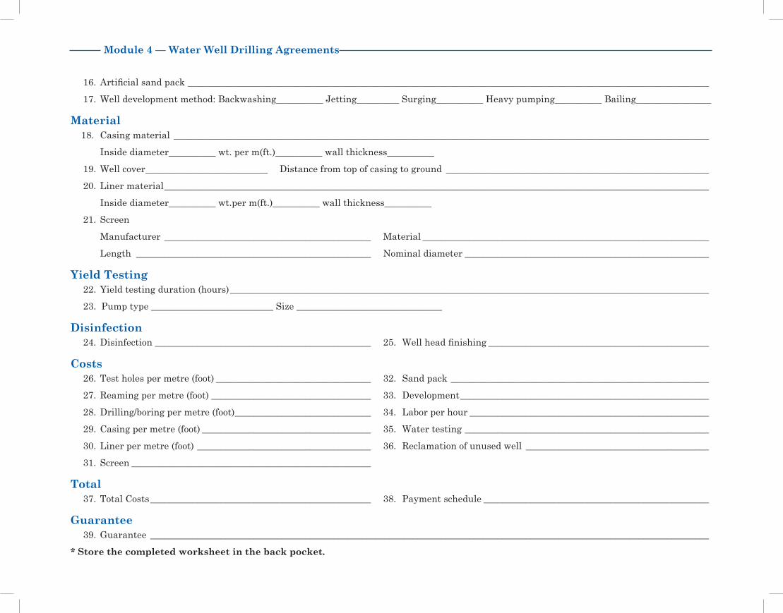
Module 4 — Water Well Drilling Agreements
16. Artificial sand pack _______________________________________________________________________________________________________________
17. Well development method: Backwashing__________ Jetting_________ Surging__________ Heavy pumping__________ Bailing________________
Material18. Casing material __________________________________________________________________________________________________________________
Inside diameter__________ wt. per m(ft.)__________ wall thickness__________
19. Well cover __________________________ Distance from top of casing to ground ________________________________________________________
20. Liner material ____________________________________________________________________________________________________________________
Inside diameter__________ wt.per m(ft.)__________ wall thickness__________
21. Screen
Manufacturer ____________________________________________ Material _____________________________________________________________
Length __________________________________________________ Nominal diameter ____________________________________________________
Yield Testing22. Yield testing duration (hours) ______________________________________________________________________________________________________
23. Pump type __________________________ Size _______________________________
Disinfection24. Disinfection ______________________________________________ 25. Well head finishing _______________________________________________
Costs26. Test holes per metre (foot) _________________________________ 32. Sand pack _______________________________________________________
27. Reaming per metre (foot) __________________________________ 33. Development _____________________________________________________
28. Drilling/boring per metre (foot) _____________________________ 34. Labor per hour ___________________________________________________
29. Casing per metre (foot) ____________________________________ 35. Water testing ____________________________________________________
30. Liner per metre (foot) _____________________________________ 36. Reclamation of unused well _______________________________________
31. Screen ___________________________________________________
Total37. Total Costs _______________________________________________ 38. Payment schedule ________________________________________________
Guarantee39. Guarantee _______________________________________________________________________________________________________________________
* Store the completed worksheet in the back pocket.

Module 5 — Monitoring and Maintenance of Your Water Well
WorksheetWater Well Monitoring Log
Year_________ Well No. _____ Qtr_____ Sec_____ Twp_____ Rge_____ W of_____Meridian Lot_____ Blk_____ Plan____
Month / Day Time Water Level Comments (quality, presence of sediment, yield problems)
Pumping Non-pumping
January _______
February _______
March _______
April _______
May _______
June _______
July _______
August _______
September _______
October _______
November _______
December _______
* At the end of the year, review the chart for any water level trends.
* Store the completed worksheet in the back pocket.


Module 6 — Shock Chlorination of Water Wells
WorksheetCalculating Water and Chlorine Requirements (200 PPM) for Shock Chlorination
Complete the following table using your own figures to determine how much water and chlorine you need to shock chlorinate your well.
Casing Diameter Volume ofWater Needed
5 1/4% 1DomesticChlorine Bleach
12% Industrial Sodium Hypochlorite
270% High Test CalciumHypochlorite
(in) (mm) Imperial gal. needed per1 ft. of water in the casing L per 1 ft. (30 cm) of water L per 1 ft. (30 cm) of water Dry weight2 per 1 ft.
(30 cm) of water
4 (100) _____ft. x 1.1 gal. = _____ _____ft. x 0.019 L = _____ _____ft. x 0.008 L = _____ _____ft. x 1.44 g = ______
6 (150) _____ft. x 2.4 gal. = _____ _____ft. x 0.042 L = _____ _____ft. x 0.018 L = _____ _____ft. x 3.12 g = ______
8 (200) _____ft. x 4.2 gal. = _____ _____ft. x 0.072 L = _____ _____ft. x 0.032 L = _____ _____ft. x 5.46 g = ______
24 (600)3 extra 200 gal. _____ft. x 0.340 L = _____ _____ft. x 0.148 L = _____ _____ft. x 25.40 g = _____
36 (900)3 extra 200 gal. _____ft. x 0.760 L = _____ _____ft. x 0.34 L = ______ _____ft. x 57.20 g = _____
3 See modified procedure for large diameter wells on page 53.1 Domestic chlorine bleach should not have additives or perfumes.
2 Since a dry chemical is being used, it should be mixed with water to form a chlorine solution prior to placing it in the well.
* Store the completed worksheet in the back pocket.


Module 9 — Plugging Abandoned Wells
WorksheetRecord of Well Plugging
Original landowner's name:____________________________________________________ Date of plugging:__________________________
Legal land description of well: Qtr _______________ Sec __________ Twp _________ Rge __________ W of _____ Meridian
Lot ________________ Blk __________ Plan ___________________________
GPS Location): ________________________________ Latitude: ______________________________ Longitude: __________________________________
Location reference points on the farm (i.e., distance from buildings): ____________________________________________________________________
Current well depth: ______________________ Original well depth: ________________________ Well diameter: _____________________________
Was well casing removed before plugging? ____________________________________________________________________________________________
Water characteristics: (attach any analysis done)
Reason for plugging the well: ________________________________________________________________________________________________________
___________________________________________________________________________________________________________________________________
Type and quantity of plugging material used: _________________________________________________________________________________________
___________________________________________________________________________________________________________________________________
How was material placed into the well? _______________________________________________________________________________________________
Who completed the procedure? _______________________________________________________________________________________________________
Mail a copy of this worksheet to the Groundwater Information Centre. Include a photocopy of the original drilling report if possible.
Alberta Environment and Sustainable Resource Development Groundwater Information Centre 11th Floor, Oxbridge Place 9820 - 106 Street Edmonton, Alberta T5K 2J6
* Store the completed worksheet in the back pocket.
AWWID Well ID Number: ______________________(call 780-427-2770 to obtain)
