for imt prestonwood · sherman oaks, california 91403 818.992.1619 voice energy consultant:...
TRANSCRIPT

PROJECT MANUAL FOR
IMT PRESTONWOOD Dallas, Texas
OWNER: ODEN HUGHES, LLC.
901 S. MoPac Expressway Austin, Texas 78746 512.813.7111 voice CONTRACTOR: ODEN HUGHES, LLC.
901 S. MoPac Expressway Austin, Texas 78746 512.813.7111 voice ARCHITECT: BGO ARCHITECTS
4202 Beltway Drive Addison, Texas 75001 214.520.8878 voice 214.524.8422 facsimile
CIVIL ENGINEER: CROSS ENGINEERING
106 W. Louisiana Street McKinney, Texas 75069 972.562.4409 voice 972.562.4471 facsimile STRUCTURAL ENGINEER: PARKIN, PERKINS, OLSEN
9330 LBJ Freeway, Suite 1055 Dallas, Texas 75243 214.221.2220 voice 214.221.2252 facsimile MEP ENGINEER: HGE CONSULTING
15603 Glen Chase Drive Houston, Texas 77095 281.856.7682 voice
LANDSCAPE ARCHITECT: NORRIS DESIGN
2001 Chicon Street Austin, Texas 78722 512.900.7888 voice 512.857.0978 facsimile INTERIOR DESIGNER: IMT RESIDENTIAL
15303 Ventura Boulevard Sherman Oaks, California 91403 818.992.1619 voice ENERGY CONSULTANT: USECOLOGIC / TEXENERGY SOLUTIONS
2611 E. Pioneer Drive Irving, TX 75061 972-579-2066 voice
DATE: 26 March 2015 (issue for permit)

IMT Prestonwood, Dallas, Texas TABLE OF CONTENTS BGO Project No. 13182 000110 - 1 26 March 2015
SECTION 000110
TABLE OF CONTENTS
SECTION TITLE ISSUE DATE
DIVISION 00 - PROCUREMENT AND CONTRACTING REQUIREMENTS
000110 Table of Contents ............................................................................. 26Mar15 003132 Geotechnical Data ............................................................................ 26Mar15 Geotechnical Report 007000 General Conditions........................................................................... 26Mar15 008000 Supplementary Conditions ............................................................... 26Mar15
DIVISION 01 - GENERAL REQUIREMENTS
011000 Summary .......................................................................................... 26Mar15 011000x LEED for Homes Mid-Rise Project Checklist 012000 Price and Payment Procedures ........................................................ 26Mar15 012100 Allowances ....................................................................................... 26Mar15 012200 Unit Prices ........................................................................................ 26Mar15 013000 Administrative Requirements ........................................................... 26Mar15 013216 Construction Progress Schedule ...................................................... 26Mar15 014000 Quality Requirements ....................................................................... 26Mar15 014100 Regulatory Requirements ................................................................. 26Mar15 014216 Definitions ........................................................................................ 26Mar15 015000 Temporary Facilities and Controls .................................................... 26Mar15 015300 Mold Prevention Measures ............................................................... 26Mar15 015713 Temporary Erosion and Sediment Control ....................................... 26Mar15 016000 Product Requirements ...................................................................... 26Mar15 017000 Execution and Closeout Requirements ............................................ 26Mar15 017419 Construction Waste Management and Disposal .............................. 26Mar15 017800 Closeout Submittals ......................................................................... 26Mar15 017900 Demonstration and Training ............................................................. 26Mar15
DIVISION 02 - EXISTING CONDITIONS – not used
DIVISION 03 - CONCRETE
031100 Concrete Forming (S) ....................................................................... 26Mar15 031106 Void Forms (S) ................................................................................. 26Mar15 032000 Concrete Reinforcement (S) ............................................................. 26Mar15 033000 Cast-In-Place Concrete (S) .............................................................. 26Mar15 033050 Sheet Vapor Barrier.......................................................................... 26Mar15 033536 Clear Concrete Sealer ...................................................................... 26Mar15 033816 Post-Tensioning (S).......................................................................... 26Mar15 035210 Hardrock Concrete Topping ............................................................. 26Mar15 035400 Cast Underlayment........................................................................... 26Mar15
DIVISION 04 - MASONRY
042000 Unit Masonry .................................................................................... 26Mar15 042200 Concrete Unit Masonry (S) ............................................................... 26Mar15
DIVISION 05 - METALS
051200 Structural Steel (S) ........................................................................... 26Mar15 054000 Cold-Formed Metal Framing (S) ....................................................... 26Mar15 055000 Metal Fabrications (S) ...................................................................... 26Mar15 055100 Metal Stairs ...................................................................................... 26Mar15 055213 Pipe and Tube Railings .................................................................... 26Mar15 057300 Decorative Railings .......................................................................... 26Mar15 057316 Cable Guardrail System ................................................................... 26Mar15
DIVISION 06 - WOOD, PLASTICS, AND COMPOSITES
061000 Rough Carpentry - Structural ........................................................... 26Mar15 061100 Architectural Rough Carpentry ......................................................... 26Mar15 061753 Prefabricated Wood Trusses (S) ...................................................... 26Mar15 062000 Finish Carpentry ............................................................................... 26Mar15
SECTION TITLE ISSUE DATE
IMT Prestonwood, Dallas, Texas TABLE OF CONTENTS BGO Project No. 13182 000110 - 2 26 March 2015
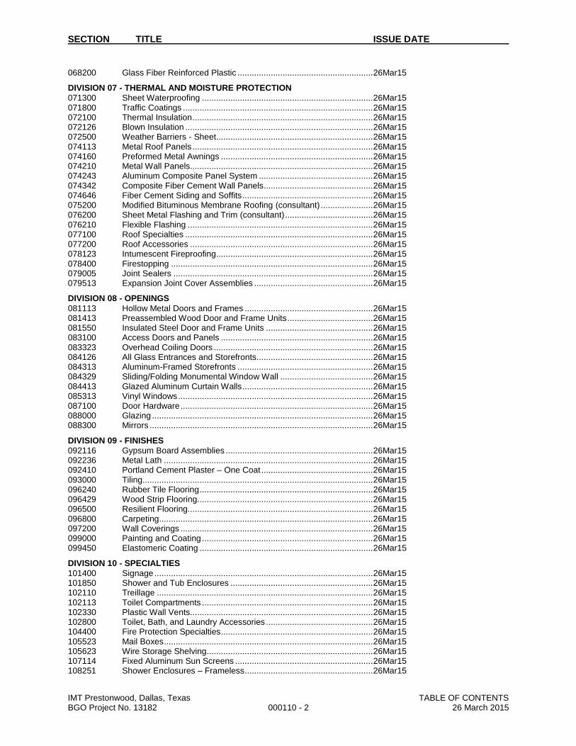
068200 Glass Fiber Reinforced Plastic ......................................................... 26Mar15
DIVISION 07 - THERMAL AND MOISTURE PROTECTION
071300 Sheet Waterproofing ........................................................................ 26Mar15 071800 Traffic Coatings ................................................................................ 26Mar15 072100 Thermal Insulation ............................................................................ 26Mar15 072126 Blown Insulation ............................................................................... 26Mar15 072500 Weather Barriers - Sheet .................................................................. 26Mar15 074113 Metal Roof Panels ............................................................................ 26Mar15 074160 Preformed Metal Awnings ................................................................ 26Mar15 074210 Metal Wall Panels............................................................................. 26Mar15 074243 Aluminum Composite Panel System ................................................ 26Mar15 074342 Composite Fiber Cement Wall Panels .............................................. 26Mar15 074646 Fiber Cement Siding and Soffits ....................................................... 26Mar15 075200 Modified Bituminous Membrane Roofing (consultant) ...................... 26Mar15 076200 Sheet Metal Flashing and Trim (consultant) ..................................... 26Mar15 076210 Flexible Flashing .............................................................................. 26Mar15 077100 Roof Specialties ............................................................................... 26Mar15 077200 Roof Accessories ............................................................................. 26Mar15 078123 Intumescent Fireproofing .................................................................. 26Mar15 078400 Firestopping ..................................................................................... 26Mar15 079005 Joint Sealers .................................................................................... 26Mar15 079513 Expansion Joint Cover Assemblies .................................................. 26Mar15
DIVISION 08 - OPENINGS
081113 Hollow Metal Doors and Frames ...................................................... 26Mar15 081413 Preassembled Wood Door and Frame Units .................................... 26Mar15 081550 Insulated Steel Door and Frame Units ............................................. 26Mar15 083100 Access Doors and Panels ................................................................ 26Mar15 083323 Overhead Coiling Doors ................................................................... 26Mar15 084126 All Glass Entrances and Storefronts................................................. 26Mar15 084313 Aluminum-Framed Storefronts ......................................................... 26Mar15 084329 Sliding/Folding Monumental Window Wall ....................................... 26Mar15 084413 Glazed Aluminum Curtain Walls ....................................................... 26Mar15 085313 Vinyl Windows .................................................................................. 26Mar15 087100 Door Hardware ................................................................................. 26Mar15 088000 Glazing ............................................................................................. 26Mar15 088300 Mirrors .............................................................................................. 26Mar15
DIVISION 09 - FINISHES
092116 Gypsum Board Assemblies .............................................................. 26Mar15 092236 Metal Lath ........................................................................................ 26Mar15 092410 Portland Cement Plaster – One Coat ............................................... 26Mar15 093000 Tiling ................................................................................................. 26Mar15 096240 Rubber Tile Flooring ......................................................................... 26Mar15 096429 Wood Strip Flooring.......................................................................... 26Mar15 096500 Resilient Flooring.............................................................................. 26Mar15 096800 Carpeting .......................................................................................... 26Mar15 097200 Wall Coverings ................................................................................. 26Mar15 099000 Painting and Coating ........................................................................ 26Mar15 099450 Elastomeric Coating ......................................................................... 26Mar15
DIVISION 10 - SPECIALTIES
101400 Signage ............................................................................................ 26Mar15 101850 Shower and Tub Enclosures ............................................................ 26Mar15 102110 Treillage ........................................................................................... 26Mar15 102113 Toilet Compartments ........................................................................ 26Mar15 102330 Plastic Wall Vents............................................................................. 26Mar15 102800 Toilet, Bath, and Laundry Accessories ............................................. 26Mar15 104400 Fire Protection Specialties ................................................................ 26Mar15 105523 Mail Boxes ........................................................................................ 26Mar15 105623 Wire Storage Shelving ...................................................................... 26Mar15 107114 Fixed Aluminum Sun Screens .......................................................... 26Mar15 108251 Shower Enclosures – Frameless ...................................................... 26Mar15

SECTION TITLE ISSUE DATE
IMT Prestonwood, Dallas, Texas TABLE OF CONTENTS BGO Project No. 13182 000110 - 3 26 March 2015
109900 Miscellaneous Specialties ................................................................ 26Mar15
DIVISION 11 - EQUIPMENT
113100 Residential Appliances ..................................................................... 26Mar15 114530 Retractable Stairs ............................................................................. 26Mar15
DIVISION 12 - FURNISHINGS
122113 Horizontal Louver Blinds .................................................................. 26Mar15 123530 Residential Casework ....................................................................... 26Mar15 123600 Countertops ...................................................................................... 26Mar15
DIVISION 13 - SPECIAL CONSTRUCTION – not used
DIVISION 14 - CONVEYING EQUIPMENT
142100 Electric Traction Elevators ................................................................ 26Mar15 149100 Trash Chutes .................................................................................... 26Mar15
DIVISION 21 – FIRE SUPPRESSION
DIVISION 22 - PLUMBING
DIVISION 23 – HEATING, VENTILATING, AND AIR CONDITIONING
DIVISION 26 - ELECTRICAL
DIVISION 28 – ELECTRONIC SAFETY AND SECURITY
DIVISION 31 - EARTHWORK
311000 Site Clearing ..................................................................................... 26Mar15 312000 Earthwork ........................................................................................ 26Mar15 316329 Drilled Piers (S) ................................................................................ 26Mar15
DIVISION 32 - EXTERIOR IMPROVEMENTS
321313 Concrete Paving ............................................................................... 26Mar15 321316 Decorative Concrete Paving ............................................................. 26Mar15 321713 Precast Concrete Site Accessories .................................................. 26Mar15 321723 Painted Pavement Markings ............................................................ 26Mar15 323119 Decorative Metal Fences and Gates ................................................ 26Mar15 323136 Security Gates and Operators .......................................................... 26Mar15 APPENDIX
Environmental Noise Mitigation Study, dP(A) Acoustics, Inc., dated March 2, 2015
END OF TABLE OF CONTENTS

IMT Prestonwood, Dallas, Texas GEOTECHNICAL DATA BGO Project No. 13182 003132 - 1 26 March 2015
SECTION 003132
GEOTECHNICAL DATA
PART 1 - GENERAL
1.1 SUMMARY A. This document includes information pertaining to geotechnical data.
1.2 INVESTIGATION A. An investigation of subsurface soil conditions at the building site was authorized by the Owner, and was
subsequently performed by Professional Services Industries Inc., report no. 0342802, dated March 31, 2014.
1.3 REPORT A. The Geotechnical Investigation Report is for information only, and is not a warranty of subsurface
conditions. B. The Report is made available for information only, and is not a Contract Document. C. The information contained in the Report represents design criteria, recommendations, and guidelines that
were utilized as the basis of design for the engineering of the earthwork operations, paving design, and foundation design indicated in the Contract Documents. No changes in this design criteria will be considered or permitted.
1.4 RESPONSIBILITY A. Bidders are expected to examine the site and subsurface investigation reports and then decide for
themselves the character of the materials to be encountered. B. The Architect and Owner assume no responsibility for variations in subsoil conditions, quality, or stability,
or for the presence, level, and extent of underground water. C. The Architect and Owner assume no responsibility for Bidder’s interpretation of data contained in the
Report.
END OF SECTION


TABLE OF CONTENTS Page No.
1.0 PROJECT INFORMATION ........................................................................................ 1
1.1 Project Authorization .......................................................................................... 1 1.2 Project Description .............................................................................................. 1 1.3 Purpose and Scope of Services ....................................................................... 1
2.0 SITE AND SUBSURFACE CONDITIONS ............................................................... 3
2.1 Site Location and Description ........................................................................... 3 2.2 Field Exploration ................................................................................................. 3 2.3 Laboratory Exploration ....................................................................................... 3 2.4 Site Geology ........................................................................................................ 4 2.5 Subsurface Conditions ....................................................................................... 4 2.6 Ground Water Information ................................................................................. 5 2.7 Site Class ............................................................................................................ 5
3.0 EVALUATION AND RECOMMENDATIONS .......................................................... 7
3.1 Soil Shrink – Swell Potential ............................................................................. 7 3.2 Site Preparation and Fill Materials ................................................................... 7 3.3 Geotechnical Discussion ................................................................................... 9 3.4 Deep Foundation Recommendations ............................................................ 10 3.5 Shallow Foundation Recommendations ....................................................... 13 3.6 Floor Slab Recommendations ........................................................................ 14
4.0 PAVEMENT RECOMMENDATIONS ..................................................................... 16
4.1 Subgrade Soil Preparation .............................................................................. 16 4.2 Pavement Design .............................................................................................. 16
5.0 CONSTRUCTION CONSIDERATIONS ................................................................. 19
5.1 Secondary Design Considerations ................................................................. 19 5.2 Construction Materials Testing ....................................................................... 20 5.3 Moisture Sensitive Soils/Weather Related Concerns ................................. 20 5.4 Drainage and Groundwater Concerns ........................................................... 20 5.5 Excavations ........................................................................................................ 21
6.0 REPORT LIMITATIONS ........................................................................................... 22
APPENDIX
Vicinity Map Boring Location Plan Aerial Photograph Boring Logs Key to Terms and Symbols Used on Logs

MULTIFAMILY BUILDINGS AND PARKING GARAGE PSI REPORT NO. 0342802 ADDISON, TEXAS MARCH 31, 2014
PROFESSIONAL SERVICE INDUSTRIES, INC. PAGE 1
1.0 PROJECT INFORMATION 1.1 Project Authorization Professional Service Industries, Inc. (PSI) has completed a geotechnical exploration for the proposed apartment complex to be located on the northeast corner of Dallas North Toll Road and Arapaho Road in Addison, Texas. The geotechnical services were authorized by Mr. John Tesoriero with IMT Capital Prestonwood, LP on March 12, 2014. This geotechnical exploration was performed in general accordance with PSI Proposal No. 117361.REV2 dated March 12, 2014.
1.2 Project Description Based on information provided, the proposed construction consists of the following: Fourteen, 4-story multifamily buildings with approximately 430 units;
A 5.5-story parking garage; and
Asphalt/concrete parking and drive areas.
It is understood that the maximum parking garage column load will be on the order of 1,500 kips and the column loads for the building to be less than 250 kips. Other structural loading information is not currently available and this report is based on the following assumptions:
• Maximum wall loads being less than 4 kips per linear foot, based on dead load plus live load for the buildings
• Maximum floor load on the order of 150 pound per square foot
Pavement loading information is not available; therefore, this report is based on following:
• A minimum of 100,000 ESALs for driving lanes with a 20-year design period
• A minimum of 25,000 ESALs for parking with a 20-year design period
Based on Google Earth, the site slopes from south (Elev. +620) to north (Elev. +609). This report is based on the assumption that finished grades will be one to four feet above the existing grades. PSI should be provided with actual grading plans prior to design finalization, so that the recommendations provided herein can be revised as necessary.
The geotechnical recommendations presented in this report are based on the available project information, building locations, and the subsurface materials described in this report. If any of the noted information is incorrect, please inform PSI in writing so that we may amend those recommendations presented in this report. PSI will not be responsible for the implementation of its recommendations when the changes are not notified in the project.
1.3 Purpose and Scope of Services The purpose of this study is to explore the subsurface conditions at the site to provide foundation recommendations for the proposed structure.
The PSI’s scope of work for this project included:
• Drilling a total of thirteen (13) borings within the proposed development to exploration depths of 10 to 40 feet

MULTIFAMILY BUILDINGS AND PARKING GARAGE PSI REPORT NO. 0342802 ADDISON, TEXAS MARCH 31, 2014
PROFESSIONAL SERVICE INDUSTRIES, INC. PAGE 2
• Laboratory testing on selected samples to evaluate classification, strength and other engineering parameters of the subsurface material
• Observations of the groundwater conditions on the site
• Preparing this Geotechnical Engineering report with recommendations for foundation recommendations
The PSI’s scope of services also presents recommendations regarding the following:
• Foundation types, depths, allowable bearing capacities, and an estimate of potential settlement
• Estimated potential soil movements associated with shrinking and swelling soils
• Definition of the seismic site class using the International Building Code (IBC) 2009 edition and the USGS database
• Comments regarding factors that will impact construction and performance of the proposed construction
• Pavement recommendations for associated parking and drive areas
The scope of services also does not include an environmental assessment for determining the presence or absence of wetlands, or hazardous or toxic materials in the soil, bedrock, surface water, groundwater, or air on or below, or around this site. Any statements in this report or on the boring logs regarding odors, colors, and unusual or suspicious items or conditions are strictly for informational purposes.
MULTIFAMILY BUILDINGS AND PARKING GARAGE PSI REPORT NO. 0342802 ADDISON, TEXAS MARCH 31, 2014
PROFESSIONAL SERVICE INDUSTRIES, INC. PAGE 3
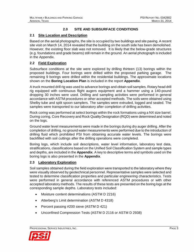
2.0 SITE AND SUBSURFACE CONDITIONS 2.1 Site Location and Description Based on the aerial photographs, the site is occupied by two buildings and site paving. A recent site visit on March 14, 2014 revealed that the building on the south side has been demolished. However, the existing floor slab was not removed. It is likely that the below-grade structures (e.g. foundations and grade beams) still remain in the ground. An aerial photograph is included in the Appendix.
2.2 Field Exploration Subsurface conditions at the site were explored by drilling thirteen (13) borings within the proposed buildings. Four borings were drilled within the proposed parking garage. The remaining 9 borings were drilled within the residential buildings. The approximate locations shown on the Boring Location Plan is included in the report Appendix.
A truck mounted drill rig was used to advance borings and obtain soil samples. Rotary head drill rig equipped with continuous flight augers equipment and a hammer using a 140-pound dropping 30 inches were used. Drilling and sampling activities were performed in general accordance with ASTM procedures or other accepted methods. The soils were obtained using Shelby tube and split spoon samplers. The samples were extruded, logged and sealed. The samples were transported to our laboratory after completion of drilling activities.
Rock coring was performed at select borings within the rock formations using a NX size barrel. During coring, Core Recovery and Rock Quality Designation (RQD) were determined and noted on the logs.
Ground water level measurements were made in the borings during dry auger drilling. After the completion of drilling, no ground water measurements were performed due to the introduction of drilling fluid which prohibited PSI from obtaining accurate water levels. The borings were backfilled with soil cuttings after the drilling operations were completed.
Boring logs, which include soil descriptions, water level information, laboratory test data, stratifications, classifications based on the Unified Soil Classification System and sample types and depths, are included in the Appendix. A key to descriptive terms and symbols used on the boring logs is also presented in the Appendix.
2.3 Laboratory Exploration Soil samples obtained during the field exploration were transported to the laboratory where they were visually observed by geotechnical personnel. Representative samples were selected and tested to determine classification properties and particular engineering characteristics. Tests were performed in general accordance with referenced ASTM procedures or with other accepted laboratory methods. The results of these tests are presented on the boring logs at the corresponding sample depths. Laboratory tests included:
• Moisture content determinations (ASTM D 2216)
• Atterberg’s Limit determination (ASTM D 4318)
• Percent passing #200 sieve (ASTM D 421)
• Unconfined Compression Tests (ASTM D 2116 or ASTM D 2938)

MULTIFAMILY BUILDINGS AND PARKING GARAGE PSI REPORT NO. 0342802 ADDISON, TEXAS MARCH 31, 2014
PROFESSIONAL SERVICE INDUSTRIES, INC. PAGE 4
The results of other laboratory tests are presented on the boring logs at the corresponding sample depths. Samples not altered by laboratory testing will be retained for 60 days from the date of this report and then discarded unless PSI is otherwise instructed in writing.
2.4 Site Geology As shown on the Dallas Sheet of the Geologic Atlas of Texas, the site is located the Cretaceous Austin Chalk Formation. The Austin Chalk Formation generally consists of high plasticity clays near the ground surface. With increasing depth, the high plasticity clays grade into moderate plasticity clays then limestone. The subsurface conditions encountered in the borings are consistent with the mapped site geology.
2.5 Subsurface Conditions In general, the subsurface conditions at the borings generally consist of fill clays overlying native clays over unweathered limestone. The depth of limestone generally increases from east to west. Fill was encountered in Borings B-7 and B-9. The fill appears to be associated with the previous earthwork around the existing building.
The boring logs and soil profiles included in the Appendix contain specific information of individual boring locations. The boring logs include soil descriptions, stratifications, penetration resistance, locations of the samples and laboratory test data and the stratifications shown represent the conditions only at the actual boring locations. Variations may occur and should be expected between boring locations. The stratifications represent the approximate boundary between subsurface materials and the actual transition may be gradual. Water level information obtained during field operations is also shown on these boring logs.
The Plasticity Index of the samples tested from these borings indicates moderate to high plasticity. Table 2.1 briefly summarizes the range of results from the field and laboratory testing programs within the parking garage. Table 2.2 briefly summarizes the range of results from the field and laboratory testing programs in the remaining areas.
The boring logs and soil profiles included in the Appendix should be reviewed for specific information at individual boring locations:
Table 2.1: General Soil Profile within the Parking Garage
Soil Stratum Type
Depth below Ground Surface
(feet)
Thickness (feet)
Moisture Content
(%)
Atterberg’s Limits
Compressive Strength
(tsf)
Fat Clay (CH), Dark Brown 0 to 4 0 to 4 20 to 44
LL: 54 to 69
PI: 30 to 36
2.5 to 4.5+**
Weathered Limestone, Tan 1 to 12 3 to 11 - -
49*
Unweathered Limestone, Gray 7 to 35 N/A - -
66 to 148*
*Compressive Strength Values **Hand Penetrometer Strength Value

MULTIFAMILY BUILDINGS AND PARKING GARAGE PSI REPORT NO. 0342802 ADDISON, TEXAS MARCH 31, 2014
PROFESSIONAL SERVICE INDUSTRIES, INC. PAGE 5
Table 2.2: General Soil Profile in the Remaining Areas
Soil Stratum Type
Depth below Ground Surface
(feet)
Thickness (feet)
Moisture Content
(%)
Atterberg’s Limits
Compressive Strength
(tsf)
Fill***: Fat to Lean Clay (CH to CL),
Dark Brown 1 to 11 9 to 10 4 to 35
LL: 40 to 72
PI: 21 to 39 2.5 to 4.5+**
Fat Clay (CH), Dark Brown 1 to 8 3 to 7 9 to 40
LL: 54 to 79
PI: 22 to 46
2 to 3*
2.5 to 4.5+**
Lean Clay (CL), Yellowish-Brown 1 to 9 2 to 5 9 to 22
LL: 40 to 50
PI; 19 to 28
3.6*
4.5+**
Weathered Limestone, Tan 1 to 19 2 to 11 8 to 18 -
49*
Unweathered Limestone, Gray 7 to 35 N/A - -
66 to 148*
*Compressive Strength Values **Hand Penetrometer Strength Value
***Encountered in Borings B-7 and B-9
2.6 Ground Water Information Groundwater was not encountered during dry augering to the top of limestone strata at the borings locations. At the limestone stratum, coring was performed using drilling fluid which prohibited PSI from obtaining accurate water levels within this stratum. It is possible that seasonal variations (temperature, rainfall, etc) will cause fluctuations in the groundwater level. Additionally, perched water may be encountered in discontinuous zones within the overburden. The groundwater levels presented in this report are the levels that were measured at the time of our field activities. We recommend that the contractor determine the actual groundwater levels at the site at the time of the construction activities to determine the impact, if any, on the construction procedures.
2.7 Site Class The International Building Code (IBC) 2009 edition was used in this report. As part of this code, the design of structures must consider dynamic forces resulting from seismic events. These forces are dependent upon the magnitude of the earthquake event as well as the properties of the soils that underlie the site.
Part of the IBC code procedure to evaluate seismic forces requires the evaluation of the Seismic Site Class, which categorizes the site based upon the characteristics of the subsurface profile within the upper 100 feet of the ground surface. To define the Seismic Site Class for this

MULTIFAMILY BUILDINGS AND PARKING GARAGE PSI REPORT NO. 0342802 ADDISON, TEXAS MARCH 31, 2014
PROFESSIONAL SERVICE INDUSTRIES, INC. PAGE 6
project, we have interpreted the results of our soil test borings drilled within the project site and estimated appropriate soil properties below the base of the boring to a depth of 100 feet, as permitted by Section 1613.5.2 of the code. The estimated soil properties were based upon data available in published geologic reports as well as our experience with subsurface conditions in the general site area.
Based upon our evaluation, it is our opinion that the subsurface conditions within the site are consistent with the characteristics of the specific Site Class C as defined in Table 1613.5.2 of the building code.

MULTIFAMILY BUILDINGS AND PARKING GARAGE PSI REPORT NO. 0342802 ADDISON, TEXAS MARCH 31, 2014
PROFESSIONAL SERVICE INDUSTRIES, INC. PAGE 7
3.0 EVALUATION AND RECOMMENDATIONS 3.1 Soil Shrink – Swell Potential The results of laboratory plasticity tests indicate that the soils at this site have high to very high potential to shrink or swell. The soils have a tendency to swell when soil moisture increases and shrink when the soil moisture decreases. The amount of potential soil movement due to shrinking and swelling with soil moisture variations is represented or indicated by Potential Vertical Rise (PVR). In designing the soil-supported structures, the structural/civil engineer should take movements associated with shrinking-swelling soils into account.
PVR estimates are based on an assumed depth known as “Active Depth” to which the soil moisture variations could occur due to seasonal variations as well as the depth to limestone. It is noted that the active depth assumed herein may not represent the moisture variations that can occur to deeper depths due to the presence of large tree root systems that could desiccate the soils, or the presence of other heating units, or possible soil wetting due to pipe leaks, poor drainage, etc. It is very difficult to predict the moisture variations under the structure during its service life. The PVR estimates provided herein should be considered approximate probable estimates based on industry standard practice and experience, and the movements predicted herein should not be construed as absolute values that could occur in the field.
Based on the borings, the clay layer thickness varies across the site and therefore the PVR values would be different at different locations across the site. PVR values of up to three inches were calculated using the Texas Department of Transportation (TXDOT) TEX-124-E method.
Poor drainage and water infiltration into the foundation soils can be detrimental to the ground supported structures. Excessive wetting of soil (due to accumulation of water), or, excessive drying (due to the presence large trees, etc) could possibly result in greater PVR values than those estimated herein. It is recommended that the moisture-related problems be corrected immediately as they can be detrimental to the ground supported structures.
3.2 Site Preparation and Fill Materials The following site preparation recommendations apply to the proposed buildings and pavement construction areas. It is recommended the topsoil, existing roots, organic material, existing fill materials and other miscellaneous debris be removed from the structural areas. A PSI representative should determine the actual depth of removal at the time of construction. After stripping of deleterious materials and excavating to the desired grade, the exposed soil should be proof-rolled to locate any soft or loose areas. Proof-rolling shall be performed in accordance with Item 216 of Texas Department of Transportation (TxDOT), Standard specification for construction of highways, streets and bridges (TxDOT Spec) or equivalent procedure. Soils that are observed to rut or deflect excessively under the moving load should be undercut and replaced with properly compacted fill materials. A PSI representative should witness the proof-rolling and undercutting activities. It is advisable to perform the earth-work activities during a period of dry weather. The proof rolled subgrade shall be scarified to a depth of 6-inches and compacted as shown in Table 3.1 at the end of this section. After the completion of proof-rolling and undercutting activities, necessary fill placement may commence.
MULTIFAMILY BUILDINGS AND PARKING GARAGE PSI REPORT NO. 0342802 ADDISON, TEXAS MARCH 31, 2014
PROFESSIONAL SERVICE INDUSTRIES, INC. PAGE 8
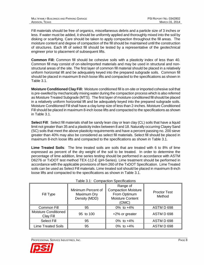
Fill materials should be free of organics, miscellaneous debris and a particle size of 3 inches or less. If water must be added, it should be uniformly applied and thoroughly mixed into the soil by disking or scarifying. Care should be taken to apply compaction throughout the fill areas. The moisture content and degree of compaction of the fill should be maintained until the construction of structures. Each lift of select fill should be tested by a representative of the geotechnical engineer prior to placement of subsequent lifts.
Common Fill: Common fill should be cohesive soils with a plasticity index of less than 40. Common fill may consist of on-site/imported materials and may be used in structural and non-structural areas of the site. The first layer of common fill material should be placed in a relatively uniform horizontal lift and be adequately keyed into the prepared subgrade soils. Common fill should be placed in maximum 8-inch loose lifts and compacted to the specifications as shown in Table 3.1.
Moisture Conditioned Clay Fill: Moisture conditioned fill is on-site or imported cohesive soil that is pre-swelled by mechanically mixing water during the compaction process which is also referred as Moisture Treated Subgrade (MTS). The first layer of moisture conditioned fill should be placed in a relatively uniform horizontal lift and be adequately keyed into the prepared subgrade soils. Moisture Conditioned Fill shall have a clay lump size of less than 2-inches. Moisture Conditioned Fill should be placed in maximum 8-inch loose lifts and compacted to the specifications as shown in Table 3.1.
Select Fill: Select fill materials shall be sandy lean clay or lean clay (CL) soils that have a liquid limit not greater than 35 and a plasticity index between 8 and 18. Naturally occurring Clayey Sand (SC) soils that meet the above plasticity requirements and have a percent passing no. 200 sieve greater than 40% may also be considered as select fill materials. Select fill should be placed in maximum 8-inch loose lifts and compacted to the specifications as shown in Table 3.1. Lime Treated Soils: The lime treated soils are soils that are treated with 6 to 8% of lime expressed as percent of the dry weight of the soil to be treated. In order to determine the percentage of lime addition, lime series testing should be performed in accordance with ASTM D6276 or TxDOT test method TEX-112-E (pH-Series). Lime treatment should be performed in accordance with the applicable provisions of Item 260 of the TxDOT Specification. Lime Treated soils can be used as Select Fill materials. Lime treated soil should be placed in maximum 8-inch loose lifts and compacted to the specifications as shown in Table 3.1.
Table 3.1: Compaction Specifications
Fill Type Minimum Percent of
Maximum Dry Density (MDD)
Range of Compaction Moisture
From Optimum Moisture Content
(OMC)
Proctor Test Method
Common Fill 95 0% to +4% ASTM D 698 Moisture Conditioned
Clay Fill 95 to 100 +2% or greater ASTM D 698
Select Fill 95 0% to +4% ASTM D 698 Lime Treated Soils 95 0% to +4% ASTM D 698

MULTIFAMILY BUILDINGS AND PARKING GARAGE PSI REPORT NO. 0342802 ADDISON, TEXAS MARCH 31, 2014
PROFESSIONAL SERVICE INDUSTRIES, INC. PAGE 9
3.3 Geotechnical Discussion Based on the layout of the new apartment complex, it appears that the proposed buildings will overlap existing buildings. It is anticipated that the existing buildings will be demolished and the foundations may be partly or entirely removed. Foundation plan details (including sizes, depths and type) for the existing buildings are unknown at this time. Based on previous experience with similar buildings, the foundation system for the existing buildings could be slab-on-grade with shallow spread footings/grade beams or piers with a grade beam system. It should be noted that the condition of the soils below the plan area of the new building would depend on the removal activities of the existing foundations. Based on the foundation removal activities and site preparation performed, the performance of the new foundations will be influenced. The foundation removal activities will depend on the type of the existing foundation system in-place. If foundations such as drilled and underream piers or straight shafts support the existing building, removal of these foundations may not be feasible and is not recommended. It is recommended that during the demolition activities, the existing deep foundation that are to be abandoned or left-in-place should be surveyed. A drawing showing the new foundation layout over the old foundations should be created in order to access the new foundations. Based on the overlay layout and the proximity of the new foundations with respect to the old foundations, the constructability and performance of the new foundations can be assessed. PSI should be given the opportunity to review the overlay plans of the old and the new foundation. After the review, PSI will confirm or amend the recommendations provided in this report as necessary. Old foundation demolition guidelines are provided below:
• The demolition activities should include the removal of the floor slabs and grade beam
system and other below grade components such as underground utilities. Voids left by removal of the below grade components should be backfilled with properly compacted select fill soils.
• If the foundation system of the existing building is a shallow spread footing/grade beam
system bearing shallower than 5 feet, it is recommended that the existing foundation system be removed in its entirety.
• If the foundation system of the existing building is a pier foundation system, it is
recommended that the shaft portions of the existing pier foundations should be saw-cut down to a depth of at least 5 feet, to maintain at least two feet of properly compacted select fill between the existing pier foundation and the proposed shallow foundation. New piers would have to straddle the old piers such that the load is not transferred to the old piers.
Two types of foundation systems were considered for the project; pier and beam foundations and shallow foundations. The recommended foundation type, floor slab and anticipated settlement for each structure are provided in Table 3.2.
MULTIFAMILY BUILDINGS AND PARKING GARAGE PSI REPORT NO. 0342802 ADDISON, TEXAS MARCH 31, 2014
PROFESSIONAL SERVICE INDUSTRIES, INC. PAGE 10
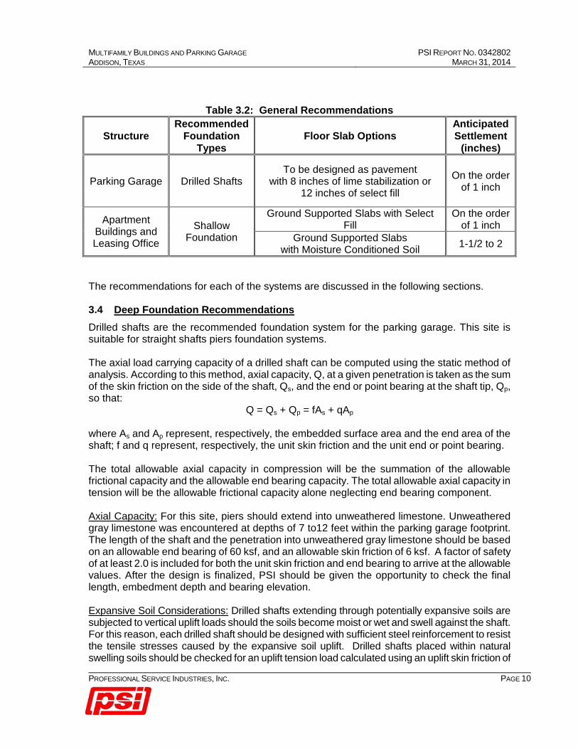
Table 3.2: General Recommendations
Structure Recommended
Foundation Types
Floor Slab Options Anticipated Settlement
(inches)
Parking Garage Drilled Shafts To be designed as pavement
with 8 inches of lime stabilization or 12 inches of select fill
On the order of 1 inch
Apartment Buildings and Leasing Office
Shallow Foundation
Ground Supported Slabs with Select Fill
On the order of 1 inch
Ground Supported Slabs with Moisture Conditioned Soil 1-1/2 to 2
The recommendations for each of the systems are discussed in the following sections.
3.4 Deep Foundation Recommendations Drilled shafts are the recommended foundation system for the parking garage. This site is suitable for straight shafts piers foundation systems. The axial load carrying capacity of a drilled shaft can be computed using the static method of analysis. According to this method, axial capacity, Q, at a given penetration is taken as the sum of the skin friction on the side of the shaft, Qs, and the end or point bearing at the shaft tip, Qp, so that:
Q = Qs + Qp = fAs + qAp where As and Ap represent, respectively, the embedded surface area and the end area of the shaft; f and q represent, respectively, the unit skin friction and the unit end or point bearing. The total allowable axial capacity in compression will be the summation of the allowable frictional capacity and the allowable end bearing capacity. The total allowable axial capacity in tension will be the allowable frictional capacity alone neglecting end bearing component. Axial Capacity: For this site, piers should extend into unweathered limestone. Unweathered gray limestone was encountered at depths of 7 to12 feet within the parking garage footprint. The length of the shaft and the penetration into unweathered gray limestone should be based on an allowable end bearing of 60 ksf, and an allowable skin friction of 6 ksf. A factor of safety of at least 2.0 is included for both the unit skin friction and end bearing to arrive at the allowable values. After the design is finalized, PSI should be given the opportunity to check the final length, embedment depth and bearing elevation. Expansive Soil Considerations: Drilled shafts extending through potentially expansive soils are subjected to vertical uplift loads should the soils become moist or wet and swell against the shaft. For this reason, each drilled shaft should be designed with sufficient steel reinforcement to resist the tensile stresses caused by the expansive soil uplift. Drilled shafts placed within natural swelling soils should be checked for an uplift tension load calculated using an uplift skin friction of

MULTIFAMILY BUILDINGS AND PARKING GARAGE PSI REPORT NO. 0342802 ADDISON, TEXAS MARCH 31, 2014
PROFESSIONAL SERVICE INDUSTRIES, INC. PAGE 11
1,000 psf for a depth of 10 feet. There should be sufficient penetration below 10 feet to provide resistance to the swelling uplift load alone. The reinforcement of the shaft should also be checked for this tension load alone neglecting any dead loads on the shaft. Wall loads should be transmitted to the drilled shafts by grade beams and the grade beam should be structurally connected to the piers. Void boxes should be provided under the grade beams to avoid movements associated with shrinking and swelling soils. A minimum 6-inch void space is recommended beneath the grade beams and pier caps. Settlement: An isolated drilled shaft having a diameter of less than 60 inches designed as discussed, the foundation settlement should be about 1 inch. A detailed group settlement analysis was not performed, as the actual group configurations are unknown at this time. However, for a shaft group bearing in limestone, we do not anticipate large settlements. If a group settlement analysis is desired, PSI should be contacted to perform such a settlement analysis. Lateral Capacity: For drilled shafts, the soils as well as the rigidity of the shaft will resist the lateral loads applied to the shaft. Once the locations, loads and other pertinent information are provided, PSI can assist in performing lateral load analyses based on methods ranging from chart solutions to the ‘p-y’ approach utilizing computer programs such as LPILE or COM 624. The lateral loads on the shaft can also be designed based on the criteria provided in the FHWA-Drilled Shaft Manual. The lateral design information regarding the 'p-y' data is provided in Table 3.3. The relationship between the soil resistance (p) and pile deflection (y) is commonly referred to as 'p-y'. Along the depth of the shaft, soil resistance (p) is expressed as a non-linear function of lateral shaft deflection (y). Various researchers developed 'p-y' criteria for different kinds of soils. The 'p-y' curves can be automatically generated utilizing the computer program LPILE. The program LPILE was developed by Lymon Reese and Shin-Tower Wang, Ensoft, Inc. ‘p-y’ parameters for LPILE analyses are provided for the analyses of individual shafts.
TABLE 3.3: SOIL PARAMETERS TO BE USED IN THE LATERAL LOAD ANALYSES
DEPTH (FEET)
‘P-Y’ CRITERIA
EFFECTIVE UNIT
WEIGHT, γ (PCF)
SU OR QU (TSF)
KS (PCI) OR KC (PCI) OR
E (PSI) ε50 OR KRM
0 to 10 Stiff Clay Criteria 125 Su = 1.0 Ks = 500
Kc = 200 0.007
Below 10 Soft Rock Criteria 135 Qu = 75.0 E = 160,000 krm = 0.0005
Note: Su-Undrained Shear Strength (tsf); Qu-Unconfined Compressive Strength (tsf); ks-modulus of subgrade reaction (pci) for static loading condition; kc-modulus of subgrade reaction (pci) for cyclic loading condition; E-Young’s modulus (psi); ε50 – strain corresponding to one-half the principle stress; krm – a constant for overall stiffness. Group Action: A group of shafts subjected to vertical loads may not necessarily have the same capacity as the sum of the capacities of the individual shafts. For axially loaded shafts, published results indicate that the ratio of capacity per pile in a group to that of a single isolated
MULTIFAMILY BUILDINGS AND PARKING GARAGE PSI REPORT NO. 0342802 ADDISON, TEXAS MARCH 31, 2014
PROFESSIONAL SERVICE INDUSTRIES, INC. PAGE 12
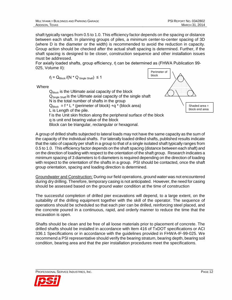
shaft typically ranges from 0.5 to 1.0. This efficiency factor depends on the spacing or distance between each shaft. In planning groups of piles, a minimum center-to-center spacing of 3D (where D is the diameter or the width) is recommended to avoid the reduction in capacity. Group action should be checked after the actual shaft spacing is determined. Further, if the shaft spacing is designed to be closer, construction sequence and other installation issues must be addressed. For axially loaded shafts, group efficiency, ή can be determined as (FHWA Publication 99-025, Volume II):
ή = QBlock /(N * Q Single Shaft) ≤ 1 Where
QBlock is the Ultimate axial capacity of the block QSingle Shaft is the Ultimate axial capacity of the single shaft
N is the total number of shafts in the group QBlock = f * L * (perimeter of block) +q * (block area) L is Length of the pile. f is the Unit skin friction along the peripheral surface of the block q is unit end bearing value of the block Block can be triangular, rectangular or hexagonal.
A group of drilled shafts subjected to lateral loads may not have the same capacity as the sum of the capacity of the individual shafts. For laterally loaded drilled shafts, published results indicate that the ratio of capacity per shaft in a group to that of a single isolated shaft typically ranges from 0.5 to 1.0. This efficiency factor depends on the shaft spacing (distance between each shaft) and on the direction of loading with respect to the orientation of the shaft group. Research indicates a minimum spacing of 3 diameters to 6 diameters is required depending on the direction of loading with respect to the orientation of the shafts in a group. PSI should be contacted, once the shaft group orientation, spacing and loading direction is determined. Groundwater and Construction: During our field operations, ground water was not encountered during dry drilling. Therefore, temporary casing is not anticipated. However, the need for casing should be assessed based on the ground water condition at the time of construction The successful completion of drilled pier excavations will depend, to a large extent, on the suitability of the drilling equipment together with the skill of the operator. The sequence of operations should be scheduled so that each pier can be drilled, reinforcing steel placed, and the concrete poured in a continuous, rapid, and orderly manner to reduce the time that the excavation is open. Shafts should be clean and be free of all loose materials prior to placement of concrete. The drilled shafts should be installed in accordance with Item 416 of TxDOT specifications or ACI 336.1 Specifications or in accordance with the guidelines provided in FHWA-IF-99-025. We recommend a PSI representative should verify the bearing stratum, bearing depth, bearing soil condition, bearing area and that the pier installation procedures meet the specifications.
Shaded area = block end area
Perimeter of block
MULTIFAMILY BUILDINGS AND PARKING GARAGE PSI REPORT NO. 0342802 ADDISON, TEXAS MARCH 31, 2014
PROFESSIONAL SERVICE INDUSTRIES, INC. PAGE 13
3.5 Shallow Foundation Recommendations The proposed residential buildings may be supported on steel reinforced stiffened slab-on-grade foundation system (i.e., a waffle type grade beam configuration) or spread footings, provided that some differential movement can be tolerated and provided the recommended subgrade preparation activities are performed. The subgrade should be prepared as mentioned in Section 3.2. Shallow foundations could be placed at least two feet below the finished grade on properly compacted select fill soils or on top of weathered limestone, and can be designed for a net allowable bearing pressure of 3,000 psf for dead load plus live loads, and 2,000 psf for dead plus sustained live loads, whichever results in a larger bearing area. For foundations placed two feet below the finished grade and the site prepared as discussed herein, the movements associated with shrinking and swelling soils should be less than one inch. Shallow foundations could be placed at least two feet below the finished grade on properly compacted moisture conditioned soils and can be designed for a net allowable bearing pressure of 2,400 psf for dead load plus live loads, and 1,600 psf for dead plus sustained live loads, whichever results in a larger bearing area. For foundations placed two feet below the finished grade and the site prepared as discussed herein, the movements associated with shrinking and swelling soils should be less than one inch. The grade beams should have a minimum width of 10 inches even if the actual bearing pressure is less than the design value. The perimeter grade beams should bear at least 24 inches below adjacent surface grades (i.e. bottoms of beams and pads should bear at least 24 inches below the adjacent ground surface). If soft or loose soils are encountered at the design bearing level, they should be undercut to stiff or dense soils and the excavation back-filled with concrete. Single isolated footing, with width no larger than eight feet, designed as discussed above, should experience a settlement of less than one inch. If a cluster of closely spaced footings (i.e., if the center to center spacing of the footings is less than two times the width of the footing) are planned, PSI should be contacted to calculate the amount of settlement. The base adhesion/frictional resistance and the passive soil resistance will resist the horizontal loads on shallow foundations. For a footing cast against natural clay soil or compacted soil, the adhesion/frictional resistance and the passive soil resistance values for both transient and sustained loading conditions are given herein. For transient loading conditions, an ultimate base adhesion resistance of 400 psf and an ultimate passive resistance of 1,600 psf can be used. For sustained loading conditions, a frictional co-efficient of 0.36 and an ultimate passive resistance of 240 psf per foot depth is recommended. A factor of safety of 2.0 is recommended to arrive at the allowable values. Passive resistance from the upper two feet of soil should be neglected. Also, the passive resistance of any un-compacted fill material should be neglected. The uplift resistance of a shallow foundation formed in an open excavation will be limited to the weight of the foundation concrete and the soil above it. For design purposes, the ultimate uplift resistance should be based on effective unit weights of 120 and 150 pcf for soil and concrete, respectively. This value should then be reduced by an appropriate factor of safety to arrive at

MULTIFAMILY BUILDINGS AND PARKING GARAGE PSI REPORT NO. 0342802 ADDISON, TEXAS MARCH 31, 2014
PROFESSIONAL SERVICE INDUSTRIES, INC. PAGE 14
the allowable uplift load. If there is a chance of submergence, the buoyant unit weights should be used. The foundation excavations should be observed by a representative of PSI prior to steel or concrete placement to assess that the foundation materials are capable of supporting the design loads and are consistent with the materials discussed in this report. Soft or loose soil zones encountered at the bottom of the footing or grade beam excavations should be removed and replaced with properly compacted fill as directed by the geotechnical engineer. After opening, footing or grade beam excavations should be observed and concrete placed as quickly as possible to avoid exposure of the footing or grade beam bottoms to wetting and drying. Surface run-off water should be drained away from the excavations and not be allowed to pond. If possible, the foundation concrete should be placed during the same day the excavation is made. If it is required that footing or grade beam excavations be left open for more than one day, they should be protected to reduce evaporation or entry of moisture. 3.6 Floor Slab Recommendations A ground supported slab can be constructed provided the movements associated with shrinking and swelling soils are reduced to a tolerable level and the owner understands the risk associated with such movements. Typically, it is the industry practice to consider one-inch soil movement as the tolerable level. In order to reduce the soil movements, it has been the industry practice to provide an engineered soil layer below the ground supported slab system. The options for providing engineered layer are recommended below. An allowable net bearing pressure of 600 psf can be used for slabs-on-grade bearing on compacted fill. If the site is prepared as recommended below, total settlement of the ground supported slabs should not exceed one inch. A vapor retarder such as polyethylene sheeting should be provided directly beneath the ground supported slabs. Adequate construction joints and reinforcement should be provided to reduce the potential for cracking of the floor slabs due to differential movement. Option 1: Select Fill
In order to reduce the PVR to about one inch, it is recommended that at least five (5) feet of low-expansive select fill should be placed below the floor-slab. The excavation can be terminated if limestone is encountered within 5 feet. The select fill should be placed within the plan area of the structure and to a distance of at least 5 feet beyond the perimeter of the structures. Plasticity and compaction requirements for the select fill are provided in the Site Preparation Section 3.2.
Option 2: Select Fill and Moisture Conditioned Clay
For this option, in order to reduce the PVR to about one inch, the engineered soil layers below the slab are given in Table 3.4.
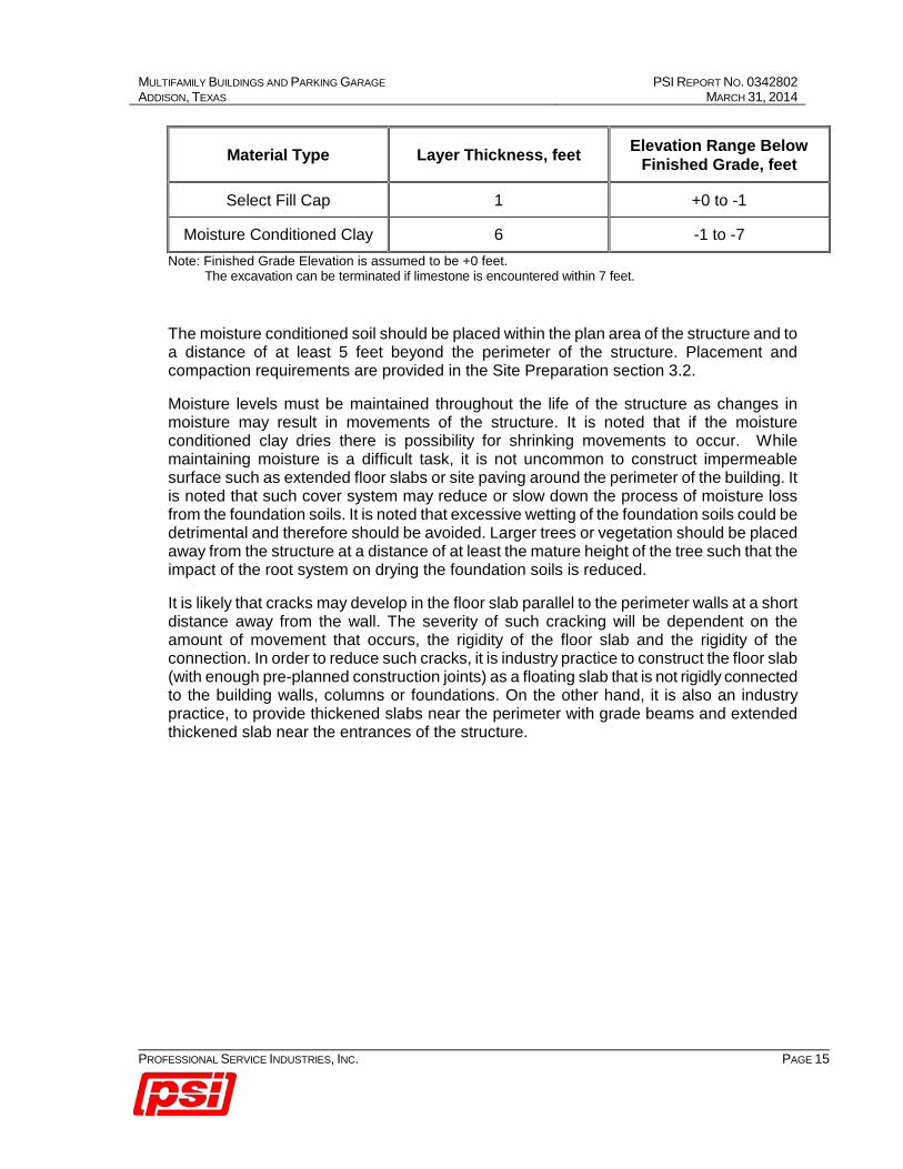
Table 3.4: Moisture Condition Clay Recommendations
MULTIFAMILY BUILDINGS AND PARKING GARAGE PSI REPORT NO. 0342802 ADDISON, TEXAS MARCH 31, 2014
PROFESSIONAL SERVICE INDUSTRIES, INC. PAGE 15
Material Type Layer Thickness, feet Elevation Range Below Finished Grade, feet
Select Fill Cap 1 +0 to -1
Moisture Conditioned Clay 6 -1 to -7 Note: Finished Grade Elevation is assumed to be +0 feet. The excavation can be terminated if limestone is encountered within 7 feet.
The moisture conditioned soil should be placed within the plan area of the structure and to a distance of at least 5 feet beyond the perimeter of the structure. Placement and compaction requirements are provided in the Site Preparation section 3.2.
Moisture levels must be maintained throughout the life of the structure as changes in moisture may result in movements of the structure. It is noted that if the moisture conditioned clay dries there is possibility for shrinking movements to occur. While maintaining moisture is a difficult task, it is not uncommon to construct impermeable surface such as extended floor slabs or site paving around the perimeter of the building. It is noted that such cover system may reduce or slow down the process of moisture loss from the foundation soils. It is noted that excessive wetting of the foundation soils could be detrimental and therefore should be avoided. Larger trees or vegetation should be placed away from the structure at a distance of at least the mature height of the tree such that the impact of the root system on drying the foundation soils is reduced.
It is likely that cracks may develop in the floor slab parallel to the perimeter walls at a short distance away from the wall. The severity of such cracking will be dependent on the amount of movement that occurs, the rigidity of the floor slab and the rigidity of the connection. In order to reduce such cracks, it is industry practice to construct the floor slab (with enough pre-planned construction joints) as a floating slab that is not rigidly connected to the building walls, columns or foundations. On the other hand, it is also an industry practice, to provide thickened slabs near the perimeter with grade beams and extended thickened slab near the entrances of the structure.
MULTIFAMILY BUILDINGS AND PARKING GARAGE PSI REPORT NO. 0342802 ADDISON, TEXAS MARCH 31, 2014
PROFESSIONAL SERVICE INDUSTRIES, INC. PAGE 16
4.0 PAVEMENT RECOMMENDATIONS In order to design a pavement, the subgrade soil conditions and anticipated levels of traffic must be known. The subgrade soils are evaluated based on the limited testing. The anticipated traffic on the proposed pavement is not known at this time. Based on the previous experience with similar facilities, the traffic for the proposed pavement could include lightly loaded cars/pick trucks, delivery vans or trucks and dump trucks.
For the design and the construction of new pavements, the following recommendations apply.
4.1 Subgrade Soil Preparation In order to provide adequate support, the subgrade soil should be properly prepared. Pavements placed directly on expansive clay soils could experience movements. Therefore, for pavements placed directly on clay soils, it is recommended that at least the upper 8 inches of the soils should be lime stabilized. Lime stabilization should be performed as discussed in Section 3.2 Site Preparation and Fill Materials of this report. Alternatively, the upper 12 inches of the soils can be replaced with select fill at described in Section 3.2.
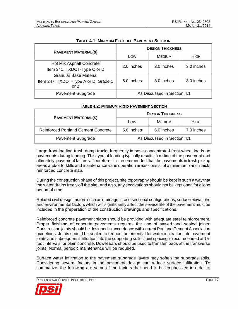
4.2 Pavement Design AASHTO design methodology can be used to design the pavements. According to AASHTO design methodology, the pavement design thickness primarily depends on strength of the subgrade soils and type of traffic. Traffic includes several types of vehicles with various magnitudes of axle loads that may be subjected to the pavement during its service life. The design involves a traffic analyses that converts various types of vehicles with various magnitudes axle loads to a number of 18-kip equivalent single axle load repetitions. The design engineer should perform the traffic analyses to compute the number of ESALs repetitions that would be subjected to the pavement during its service life or design life. Based on the computed ESALs, an economical and appropriate pavement can be designed accordingly. AASHTO low volume design methodology can also be used to design pavements. The low volume design methodology depends on typical subgrade conditions for 6 different U.S climatic zones and provides minimum thickness for 3 different levels of traffic. Based on AASHTO low volume design and our previous experience, we have provided pavement thickness for both flexible pavement and rigid pavement systems in the tables below. The tables below include thickness design corresponding to 3 levels of traffic (low, medium and high). It is recommended that the pavement design thicknesses correspond to low traffic condition be used for parking areas expected to receive only car traffic. Medium traffic condition refers to secondary drive areas and/or parking areas expected to receive delivery vans or light trucks. It is recommend that the thickness design corresponding to high traffic condition be used for frequently used areas with heavy traffic, such as trash pickup areas, main access drive areas and loading/unloading area where 18-wheeler traffic is anticipated.
MULTIFAMILY BUILDINGS AND PARKING GARAGE PSI REPORT NO. 0342802 ADDISON, TEXAS MARCH 31, 2014
PROFESSIONAL SERVICE INDUSTRIES, INC. PAGE 17
TABLE 4.1: MINIMUM FLEXIBLE PAVEMENT SECTION
PAVEMENT MATERIAL(S) DESIGN THICKNESS
LOW MEDIUM HIGH Hot Mix Asphalt Concrete
Item 341. TXDOT-Type C or D 2.0 inches 2.0 inches 3.0 inches
Granular Base Material Item 247. TXDOT-Type A or D, Grade 1
or 2 6.0 inches 8.0 inches 8.0 inches
Pavement Subgrade As Discussed in Section 4.1
TABLE 4.2: MINIMUM RIGID PAVEMENT SECTION
PAVEMENT MATERIAL(S) DESIGN THICKNESS
LOW MEDIUM HIGH
Reinforced Portland Cement Concrete 5.0 inches 6.0 inches 7.0 inches
Pavement Subgrade As Discussed in Section 4.1
Large front-loading trash dump trucks frequently impose concentrated front-wheel loads on pavements during loading. This type of loading typically results in rutting of the pavement and ultimately, pavement failures. Therefore, it is recommended that the pavements in trash pickup areas and/or forklifts and maintenance vans operation areas consist of a minimum 7-inch thick, reinforced concrete slab. During the construction phase of this project, site topography should be kept in such a way that the water drains freely off the site. And also, any excavations should not be kept open for a long period of time. Related civil design factors such as drainage, cross-sectional configurations, surface elevations and environmental factors which will significantly affect the service life of the pavement must be included in the preparation of the construction drawings and specifications. Reinforced concrete pavement slabs should be provided with adequate steel reinforcement. Proper finishing of concrete pavements requires the use of sawed and sealed joints. Construction joints should be designed in accordance with current Portland Cement Association guidelines. Joints should be sealed to reduce the potential for water infiltration into pavement joints and subsequent infiltration into the supporting soils. Joint spacing is recommended at 15-foot intervals for plain concrete. Dowel bars should be used to transfer loads at the transverse joints. Normal periodic maintenance will be required. Surface water infiltration to the pavement subgrade layers may soften the subgrade soils. Considering several factors in the pavement design can reduce surface infiltration. To summarize, the following are some of the factors that need to be emphasized in order to

MULTIFAMILY BUILDINGS AND PARKING GARAGE PSI REPORT NO. 0342802 ADDISON, TEXAS MARCH 31, 2014
PROFESSIONAL SERVICE INDUSTRIES, INC. PAGE 18
maintain proper drainage.
1) Appropriate slopes should be provided to drain the water freely from the pavement surface.
2) Joints should be properly sealed and maintained.
3) Side drains or sub drains along a pavement section may be provided.
4) Proper pavement maintenance programs such as sealing surface cracks, and immediate repair of distressed pavement areas should be adopted.
If a curb and gutter system is used, the curb should extend through the base and at least 3 inches into the subgrade. This will help reduce migration of subsurface water into the pavement base course from adjacent areas.
MULTIFAMILY BUILDINGS AND PARKING GARAGE PSI REPORT NO. 0342802 ADDISON, TEXAS MARCH 31, 2014
PROFESSIONAL SERVICE INDUSTRIES, INC. PAGE 19
5.0 CONSTRUCTION CONSIDERATIONS It is recommended that PSI be retained to provide observation and testing of construction activities involved in the foundations, earthwork and related activities of this project. PSI cannot accept any responsibility for any conditions which deviate from those described in this report, nor for the performance of the structures if not engaged to also provide construction observation and testing for this project. 5.1 Secondary Design Considerations The following information has been developed after review of numerous problems concerning foundations throughout the area. It is presented here for your convenience. If these features are incorporated in the overall design and specifications for the project, performance of the project will be improved.
1. Prior to construction, the area to be covered by buildings should be prepared so that water will not pond beneath or around the buildings after periods of rainfall. In addition, water should not be allowed to pond on or around pavements.
2. Roof drainage should be collected and transmitted by pipe to a storm drainage system or to an area where the water can drain away from buildings and pavements without entering the soils supporting buildings and pavements.
3. Sidewalks should not be structurally connected to buildings. They should be sloped away from buildings so that water will be drained away from structures.
4. Paved areas and the general ground surface should be sloped away from buildings on all sides so that water will always drain away from the structures. Water should not be allowed to pond near buildings after the floor slabs and foundations have been constructed.
5. Backfill for utility lines that are located in pavement, sidewalk and building areas should consist of on-site fill. The backfill should be compacted as described in the Site Preparation and Fill Materials section of this report. Lesser lift thicknesses may be required to obtain adequate compaction.
6. Care should be exercised to make sure that ditches for utility lines do not serve as conduits that transmit water beneath structures or pavements. The top of the ditch should be sealed to inhibit the inflow of surface water during periods of rainfall.
7. Flower beds and planting areas should not be constructed along building perimeters. Constructing sidewalks or pavements adjacent to buildings would be preferable. If required, flower beds and planting areas could be constructed beyond the sidewalks away from the buildings. If it is desired to have flower beds and planting areas adjacent to a building, the use of above grade concrete box planters, or other methods that reduce the likelihood of large changes in moisture content of soils adjacent to or below structures should be considered.
8. Water sprinkling systems should not be located where water will be sprayed onto building walls and subsequently drain downward and flow into the soils beneath foundations.
9. Trees in general should not be planted closer to a structure than the mature height of the tree. A tree planted closer to a structure than the recommended distance may extend its roots beneath the structure, allowing removal of subgrade moisture and/or causing structural distress.
MULTIFAMILY BUILDINGS AND PARKING GARAGE PSI REPORT NO. 0342802 ADDISON, TEXAS MARCH 31, 2014
PROFESSIONAL SERVICE INDUSTRIES, INC. PAGE 20
10. Utilities that project through slab-on-grade floors should be designed with some degree of flexibility and/or with a sleeve to reduce the potential for damage to the utilities should movement occur.
11. Soil supported floor slabs are subject to vertical movements. This often causes distress to interior wall partitions supported on soil supported floor slabs. This should be considered in the design of soil supported floor slabs.
5.2 Construction Materials Testing It is recommended that PSI be retained to provide observation and testing of construction activities involved in the foundations and pavements, earthwork, and related activities of this project. PSI cannot accept any responsibility for any conditions that deviates from those described in this report, nor for the performance of the foundations and pavements if not engaged to also provide construction observation and testing for this project.
Observation of all foundation bearing materials, pier construction activities, structural steel and subgrade treatment operations should be performed by a representative of PSI. Density testing should be performed at a rate of one per 2,500 square feet per 8-inch lift in building areas, one test per 10,000-square feet per 8-inch lift in paved areas and 1 per 100 linear feet per 8-inch lift in utility trench backfill. A moisture-density relationship (Proctor), Atterberg’s limit and minus 200 sieve test should be performed for each material encountered at finished subgrade elevation.
5.3 Moisture Sensitive Soils/Weather Related Concerns The upper soils encountered at this site are cohesive soils. These soils may become sensitive to disturbances caused by construction traffic and changes in moisture content. During wet weather periods, increases in the moisture content of the soil can cause significant reduction in the soil strength and support capabilities. In addition, soils which become wet may be slow to dry and thus significantly retard the progress of grading and compaction activities. It will, therefore, be advantageous to perform earthwork and foundation construction activities during dry weather. 5.4 Drainage and Groundwater Concerns Water should not be allowed to collect in any excavations or on prepared subgrades of the construction area either during or after construction. Undercut or excavated areas should be sloped toward one corner to facilitate removal of collected rainwater, groundwater, or surface runoff. Positive site surface drainage should be provided to reduce infiltration of surface water and the grades should be sloped away from the subgrade soils. Groundwater water was encountered at a depth at depths ranging from 9 to 19 feet. However, it is possible that seasonal variations will cause fluctuations in the groundwater level. Water accumulation should be removed from excavations by pumping. The Geotechnical engineer should be consulted, if excessive and uncontrolled amounts of seepage occur.

MULTIFAMILY BUILDINGS AND PARKING GARAGE PSI REPORT NO. 0342802 ADDISON, TEXAS MARCH 31, 2014
PROFESSIONAL SERVICE INDUSTRIES, INC. PAGE 21
5.5 Excavations In Federal Register, Volume 54, No. 209 (October 1989), the United States Department of Labor, Occupational Safety and Health Administration (OSHA) amended its "Construction Standards for Excavations, 29 CFR, part 1926, Subpart P". This document was issued to better insure the safety of workmen entering trenches or excavations. It is mandated by this federal regulation that excavations, whether they be utility trenches, basement excavation or footing excavations, be constructed in accordance with the new OSHA guidelines. It is understood that these regulations are being strictly enforced and if they are not closely followed, the owner and the contractor could be liable for substantial penalties. The contractor is solely responsible for designing and constructing stable, temporary excavations and should shore, slope, or bench the sides of the excavations as required to maintain stability of both the excavation sides and bottom. The contractor's "responsible person", as defined in 29 CFR Part 1926, should evaluate the soil exposed in the excavations as part of the contractor's safety procedures. In no case should slope height, slope inclination, or excavation depth, including utility trench excavation depth, exceed those specified in local, state, and federal safety regulations. We are providing this information solely as a service to the client. PSI does not assume responsibility for construction site safety or the contractor's or other party’s compliance with local, state, and federal safety or other regulations.

MULTIFAMILY BUILDINGS AND PARKING GARAGE PSI REPORT NO. 0342802 ADDISON, TEXAS MARCH 31, 2014
PROFESSIONAL SERVICE INDUSTRIES, INC. PAGE 22
6.0 REPORT LIMITATIONS The recommendations submitted in this report are based on the available subsurface information obtained by PSI and design details furnished by IMT Capital Prestonwood, LP for the proposed project. If there are any revisions to the plans for this project, or if deviations from the subsurface conditions noted in this report are encountered during construction, PSI should be notified immediately to determine if changes in the foundation recommendations are required. If PSI is not notified of such changes, PSI will not be responsible for the impact of those changes on the project.
The geotechnical engineer warrants that the findings, recommendations, specifications, or professional advice contained herein have been made in accordance with generally accepted professional geotechnical engineering practices in the local area. No other warranties are implied or expressed. This report may not be copied, except in the entirety, without expressed written permission from PSI.
After the plans and specifications are more complete, the Geotechnical Engineer should be retained and provided the opportunity to review the final design plans and specifications to check that our engineering recommendations have been properly incorporated into the design documents. At this time, it may be necessary to submit supplementary recommendations. If PSI is not retained to perform these functions, PSI will not be responsible for the impact of those conditions on the project. This report has been prepared for the exclusive use of IMT Capital Prestonwood, LP for the specific application to the proposed buildings in Addison, Texas.

________________________________________________________________________________________ Multifamily Buildings and Parking Garage, Addison, TX Professional Service Industries, Inc.
APPENDIX

4087 Shilling Way - Dallas, Texas 75237 (214) 330-9211 - FAX (214) 333-2853
Site Vicinity Map 0342802
N
Multifamily Buildings and Parking Garage Dallas North Toll Road and Arapaho Road
Addison, Texas
SITE

4087 Shilling Way - Dallas, Texas 75237 (214) 330-9211 - FAX (214) 333-2853
Boring Location Plan 0342802
Multifamily Buildings and Parking Garage Dallas North Toll Road and Arapaho Road
Addison, Texas
N
B-9
B-13
B-11
B-12 B-10
B-8
B-7
B-6
B-5
B-4
B-3
B-2
B-1
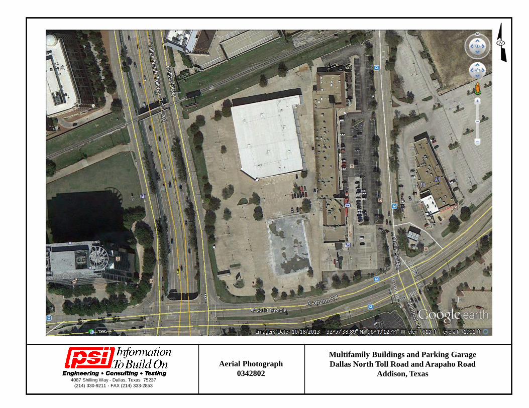
4087 Shilling Way - Dallas, Texas 75237 (214) 330-9211 - FAX (214) 333-2853
Aerial Photograph 0342802
Multifamily Buildings and Parking Garage Dallas North Toll Road and Arapaho Road
Addison, Texas
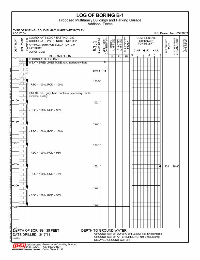
8
18
131
6" CONCRETE & 4" BASEWEATHERED LIMESTONE, tan, moderately hard
- REC = 100%, RQD = 100%
LIMESTONE, gray, hard, continuous recovery, fair toexcellent quality
- REC = 100%, RQD = 98%
- REC = 100%, RQD = 100%
- REC = 100%, RQD = 96%
- REC = 100%, RQD = 78%
- REC = 100%, RQD = 55%
50/5.5"
100/5"
100/1"
100/1"
100/1"
100/1"
100/1"
100/1"
116.80
LL
UN
IT D
RY
WT
.(P
CF
)
CO
MP
RE
SS
IVE
ST
RE
NG
TH
(ts
f)
LOG OF BORING B-1
GROUND WATER DURING DRILLING: Not EncounteredGROUND WATER AFTER DRILLING: Not EncounteredDELAYED GROUND WATER:
Geotechnical Consulting Services4087 Shilling WayDallas, Texas 75237
DATE DRILLED: 3/17/14
PLA
ST
ICLI
MIT
(%
)
DEPTH TO GROUND WATER
PLA
ST
ICIT
YIN
DE
X
PL PI0 1 2 3 4 5
SA
MP
LES
NOTES:
HP
LIQ
UID
LIM
IT (
%) COMPRESSIVE
STRENGTHTONS/SQ.FT.
MO
IST
UR
EC
ON
TE
NT
(%
)
DE
PT
H,
FT
.
UUUCSO
IL T
YP
E
% P
AS
SIN
G#2
00 S
IEV
E
DESCRIPTION
DEPTH OF BORING: 35 FEET
COORDINATE (X) OR EASTING: 289COORDINATE (Y) OR NORTHING: 392
LATITUDE:LONGITUDE:
APPROX. SURFACE ELEVATION: 0.0
TYPE OF BORING: SOLID FLIGHT AUGER/WET ROTARYLOCATION: PSI Project No.: 0342802
Proposed Multifamily Buildings and Parking GarageAddison, Texas
SP
T -
NT
CP
- N
(BLO
WS
/FT
.)
BL_
DA
LLA
S -
PS
IHO
US
TO
N.G
DT
- 3
/25/
14
09:4
7 -
P:\0
342
DA
LLA
S G
EO
\201
4 G
EO
RE
PO
RT
S\0
3428
02 L
AN
DM
AR
K P
RE
ST
ON
AD
DIS
ON
, TX
- IM
T C
AP
ITA
L III
PR
ES
TO
NW
OO
D, L
P\L
OG
S.G
PJ
0
5
10
15
20
25
30
35
40
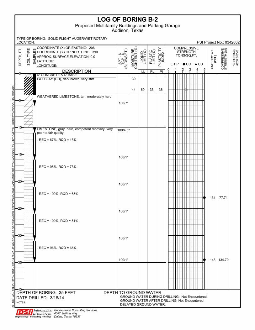
30
44 69 33 36
134
143
4" CONCRETE & 4" BASEFAT CLAY (CH), dark brown, very stiff
WEATHERED LIMESTONE, tan, moderately hard
LIMESTONE, gray, hard, competent recovery, verypoor to fair quality
- REC = 67%, RQD = 15%
- REC = 96%, RQD = 73%
- REC = 100%, RQD = 65%
- REC = 100%, RQD = 51%
- REC = 96%, RQD = 65%
100/7"
100/4.5"
100/1"
100/1"
100/1"
100/1"
100/1"
77.71
134.70
LL
UN
IT D
RY
WT
.(P
CF
)
CO
MP
RE
SS
IVE
ST
RE
NG
TH
(ts
f)
LOG OF BORING B-2
GROUND WATER DURING DRILLING: Not EncounteredGROUND WATER AFTER DRILLING: Not EncounteredDELAYED GROUND WATER:
Geotechnical Consulting Services4087 Shilling WayDallas, Texas 75237
DATE DRILLED: 3/18/14
PLA
ST
ICLI
MIT
(%
)
DEPTH TO GROUND WATER
PLA
ST
ICIT
YIN
DE
X
PL PI0 1 2 3 4 5
SA
MP
LES
NOTES:
HP
LIQ
UID
LIM
IT (
%) COMPRESSIVE
STRENGTHTONS/SQ.FT.
MO
IST
UR
EC
ON
TE
NT
(%
)
DE
PT
H,
FT
.
UUUCSO
IL T
YP
E
% P
AS
SIN
G#2
00 S
IEV
E
DESCRIPTION
DEPTH OF BORING: 35 FEET
COORDINATE (X) OR EASTING: 206COORDINATE (Y) OR NORTHING: 390
LATITUDE:LONGITUDE:
APPROX. SURFACE ELEVATION: 0.0
TYPE OF BORING: SOLID FLIGHT AUGER/WET ROTARYLOCATION: PSI Project No.: 0342802
Proposed Multifamily Buildings and Parking GarageAddison, Texas
SP
T -
NT
CP
- N
(BLO
WS
/FT
.)
BL_
DA
LLA
S -
PS
IHO
US
TO
N.G
DT
- 3
/25/
14
09:4
7 -
P:\0
342
DA
LLA
S G
EO
\201
4 G
EO
RE
PO
RT
S\0
3428
02 L
AN
DM
AR
K P
RE
ST
ON
AD
DIS
ON
, TX
- IM
T C
AP
ITA
L III
PR
ES
TO
NW
OO
D, L
P\L
OG
S.G
PJ
0
5
10
15
20
25
30
35
40
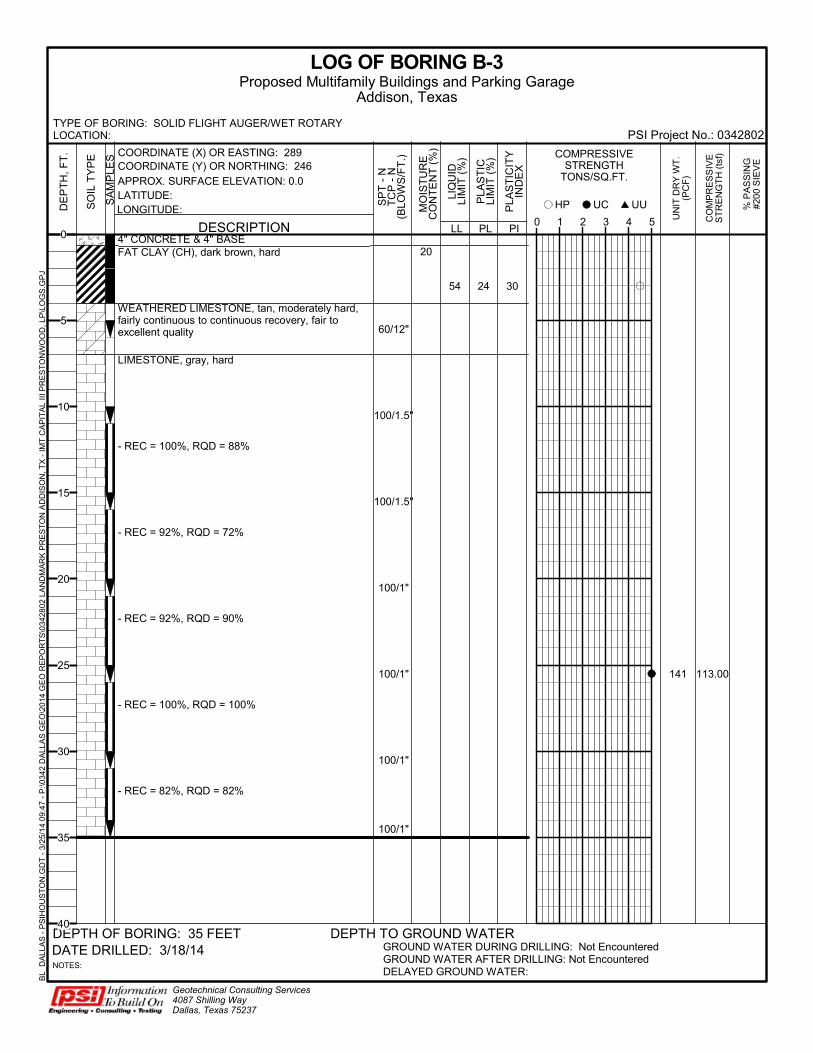
20
54 24 30
141
4" CONCRETE & 4" BASEFAT CLAY (CH), dark brown, hard
WEATHERED LIMESTONE, tan, moderately hard,fairly continuous to continuous recovery, fair toexcellent quality
LIMESTONE, gray, hard
- REC = 100%, RQD = 88%
- REC = 92%, RQD = 72%
- REC = 92%, RQD = 90%
- REC = 100%, RQD = 100%
- REC = 82%, RQD = 82%
60/12"
100/1.5"
100/1.5"
100/1"
100/1"
100/1"
100/1"
113.00
LL
UN
IT D
RY
WT
.(P
CF
)
CO
MP
RE
SS
IVE
ST
RE
NG
TH
(ts
f)
LOG OF BORING B-3
GROUND WATER DURING DRILLING: Not EncounteredGROUND WATER AFTER DRILLING: Not EncounteredDELAYED GROUND WATER:
Geotechnical Consulting Services4087 Shilling WayDallas, Texas 75237
DATE DRILLED: 3/18/14
PLA
ST
ICLI
MIT
(%
)
DEPTH TO GROUND WATER
PLA
ST
ICIT
YIN
DE
X
PL PI0 1 2 3 4 5
SA
MP
LES
NOTES:
HP
LIQ
UID
LIM
IT (
%) COMPRESSIVE
STRENGTHTONS/SQ.FT.
MO
IST
UR
EC
ON
TE
NT
(%
)
DE
PT
H,
FT
.
UUUCSO
IL T
YP
E
% P
AS
SIN
G#2
00 S
IEV
E
DESCRIPTION
DEPTH OF BORING: 35 FEET
COORDINATE (X) OR EASTING: 289COORDINATE (Y) OR NORTHING: 246
LATITUDE:LONGITUDE:
APPROX. SURFACE ELEVATION: 0.0
TYPE OF BORING: SOLID FLIGHT AUGER/WET ROTARYLOCATION: PSI Project No.: 0342802
Proposed Multifamily Buildings and Parking GarageAddison, Texas
SP
T -
NT
CP
- N
(BLO
WS
/FT
.)
BL_
DA
LLA
S -
PS
IHO
US
TO
N.G
DT
- 3
/25/
14
09:4
7 -
P:\0
342
DA
LLA
S G
EO
\201
4 G
EO
RE
PO
RT
S\0
3428
02 L
AN
DM
AR
K P
RE
ST
ON
AD
DIS
ON
, TX
- IM
T C
AP
ITA
L III
PR
ES
TO
NW
OO
D, L
P\L
OG
S.G
PJ
0
5
10
15
20
25
30
35
40

9
133
132
133
6" CONCRETE & 4" BASEWEATHERED LIMESTONE, tan, moderately hard
- REC = 72%, RQD = 0%
- REC = 53%, RQD = 27%
LIMESTONE, gray, hard, continuous recovery, goodto excellent quality- REC = 100%, RQD = 57%
- REC = 100%, RQD = 85%
- REC = 100%, RQD = 93%
- REC = 95%, RQD = 75%
- REC = 97%, RQD = 92%
- REC = 100%, RQD = 90%
100/7"
100/8"
100/2.5"
100/1"
100/1.25"
100/1"
100/1"
100/1"
49.36
66.42
148.40
LL
UN
IT D
RY
WT
.(P
CF
)
CO
MP
RE
SS
IVE
ST
RE
NG
TH
(ts
f)
LOG OF BORING B-4
GROUND WATER DURING DRILLING: Not EncounteredGROUND WATER AFTER DRILLING: Not EncounteredDELAYED GROUND WATER:
Geotechnical Consulting Services4087 Shilling WayDallas, Texas 75237
DATE DRILLED: 3/17/14
PLA
ST
ICLI
MIT
(%
)
DEPTH TO GROUND WATER
PLA
ST
ICIT
YIN
DE
X
PL PI0 1 2 3 4 5
SA
MP
LES
NOTES:
HP
LIQ
UID
LIM
IT (
%) COMPRESSIVE
STRENGTHTONS/SQ.FT.
MO
IST
UR
EC
ON
TE
NT
(%
)
DE
PT
H,
FT
.
UUUCSO
IL T
YP
E
% P
AS
SIN
G#2
00 S
IEV
E
DESCRIPTION
DEPTH OF BORING: 40 FEET
COORDINATE (X) OR EASTING: 206COORDINATE (Y) OR NORTHING: 243
LATITUDE:LONGITUDE:
APPROX. SURFACE ELEVATION: 0.0
TYPE OF BORING: SOLID FLIGHT AUGERLOCATION: PSI Project No.: 0342802
Proposed Multifamily Buildings and Parking GarageAddison, Texas
SP
T -
NT
CP
- N
(BLO
WS
/FT
.)
BL_
DA
LLA
S -
PS
IHO
US
TO
N.G
DT
- 3
/25/
14
09:4
7 -
P:\0
342
DA
LLA
S G
EO
\201
4 G
EO
RE
PO
RT
S\0
3428
02 L
AN
DM
AR
K P
RE
ST
ON
AD
DIS
ON
, TX
- IM
T C
AP
ITA
L III
PR
ES
TO
NW
OO
D, L
P\L
OG
S.G
PJ
0
5
10
15
20
25
30
35
40
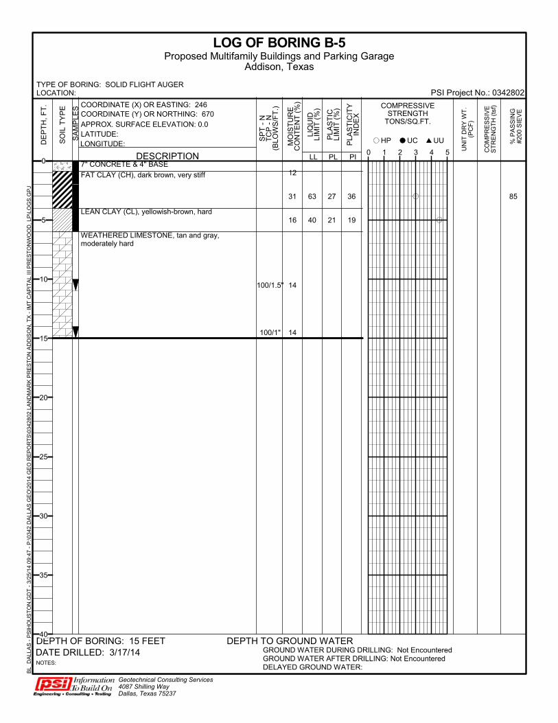
12
31
16
14
14
63
40
27
21
36
19
85
7" CONCRETE & 4" BASE
FAT CLAY (CH), dark brown, very stiff
LEAN CLAY (CL), yellowish-brown, hard
WEATHERED LIMESTONE, tan and gray,moderately hard
100/1.5"
100/1"
LL
UN
IT D
RY
WT
.(P
CF
)
CO
MP
RE
SS
IVE
ST
RE
NG
TH
(ts
f)
LOG OF BORING B-5
GROUND WATER DURING DRILLING: Not EncounteredGROUND WATER AFTER DRILLING: Not EncounteredDELAYED GROUND WATER:
Geotechnical Consulting Services4087 Shilling WayDallas, Texas 75237
DATE DRILLED: 3/17/14
PLA
ST
ICLI
MIT
(%
)
DEPTH TO GROUND WATER
PLA
ST
ICIT
YIN
DE
X
PL PI0 1 2 3 4 5
SA
MP
LES
NOTES:
HP
LIQ
UID
LIM
IT (
%) COMPRESSIVE
STRENGTHTONS/SQ.FT.
MO
IST
UR
EC
ON
TE
NT
(%
)
DE
PT
H,
FT
.
UUUCSO
IL T
YP
E
% P
AS
SIN
G#2
00 S
IEV
E
DESCRIPTION
DEPTH OF BORING: 15 FEET
COORDINATE (X) OR EASTING: 246COORDINATE (Y) OR NORTHING: 670
LATITUDE:LONGITUDE:
APPROX. SURFACE ELEVATION: 0.0
TYPE OF BORING: SOLID FLIGHT AUGERLOCATION: PSI Project No.: 0342802
Proposed Multifamily Buildings and Parking GarageAddison, Texas
SP
T -
NT
CP
- N
(BLO
WS
/FT
.)
BL_
DA
LLA
S -
PS
IHO
US
TO
N.G
DT
- 3
/25/
14
09:4
7 -
P:\0
342
DA
LLA
S G
EO
\201
4 G
EO
RE
PO
RT
S\0
3428
02 L
AN
DM
AR
K P
RE
ST
ON
AD
DIS
ON
, TX
- IM
T C
AP
ITA
L III
PR
ES
TO
NW
OO
D, L
P\L
OG
S.G
PJ
0
5
10
15
20
25
30
35
40

8
14
15
6" CONCRETE & 4" BASEWEATHERED LIMESTONE, tan, moderately hard
LIMESTONE, gray, hard
100/1.5"
100/1"
LL
UN
IT D
RY
WT
.(P
CF
)
CO
MP
RE
SS
IVE
ST
RE
NG
TH
(ts
f)
LOG OF BORING B-6
GROUND WATER DURING DRILLING: Not EncounteredGROUND WATER AFTER DRILLING: Not EncounteredDELAYED GROUND WATER:
Geotechnical Consulting Services4087 Shilling WayDallas, Texas 75237
DATE DRILLED: 3/17/14
PLA
ST
ICLI
MIT
(%
)
DEPTH TO GROUND WATER
PLA
ST
ICIT
YIN
DE
X
PL PI0 1 2 3 4 5
SA
MP
LES
NOTES:
HP
LIQ
UID
LIM
IT (
%) COMPRESSIVE
STRENGTHTONS/SQ.FT.
MO
IST
UR
EC
ON
TE
NT
(%
)
DE
PT
H,
FT
.
UUUCSO
IL T
YP
E
% P
AS
SIN
G#2
00 S
IEV
E
DESCRIPTION
DEPTH OF BORING: 10 FEET
COORDINATE (X) OR EASTING: 289COORDINATE (Y) OR NORTHING: 46
LATITUDE:LONGITUDE:
APPROX. SURFACE ELEVATION: 0.0
TYPE OF BORING: SOLID FLIGHT AUGERLOCATION: PSI Project No.: 0342802
Proposed Multifamily Buildings and Parking GarageAddison, Texas
SP
T -
NT
CP
- N
(BLO
WS
/FT
.)
BL_
DA
LLA
S -
PS
IHO
US
TO
N.G
DT
- 3
/25/
14
09:4
7 -
P:\0
342
DA
LLA
S G
EO
\201
4 G
EO
RE
PO
RT
S\0
3428
02 L
AN
DM
AR
K P
RE
ST
ON
AD
DIS
ON
, TX
- IM
T C
AP
ITA
L III
PR
ES
TO
NW
OO
D, L
P\L
OG
S.G
PJ
0
5
10
15
20
25
30
35
40

4
17
18
28
27
40
72
19
33
21
39
117
4" CONCRETE & 3" BASEFILL: FAT CLAY (CH), dark brown, very stiff to hard
WEATHERED LIMESTONE, tan, moderately hard
LIMESTONE, gray, hard 100/3"
100/1"
3.60
LL
UN
IT D
RY
WT
.(P
CF
)
CO
MP
RE
SS
IVE
ST
RE
NG
TH
(ts
f)
LOG OF BORING B-7
GROUND WATER DURING DRILLING: Not EncounteredGROUND WATER AFTER DRILLING: Not EncounteredDELAYED GROUND WATER:
Geotechnical Consulting Services4087 Shilling WayDallas, Texas 75237
DATE DRILLED: 3/18/14
PLA
ST
ICLI
MIT
(%
)
DEPTH TO GROUND WATER
PLA
ST
ICIT
YIN
DE
X
PL PI0 1 2 3 4 5
SA
MP
LES
NOTES:
HP
LIQ
UID
LIM
IT (
%) COMPRESSIVE
STRENGTHTONS/SQ.FT.
MO
IST
UR
EC
ON
TE
NT
(%
)
DE
PT
H,
FT
.
UUUCSO
IL T
YP
E
% P
AS
SIN
G#2
00 S
IEV
E
DESCRIPTION
DEPTH OF BORING: 20 FEET
COORDINATE (X) OR EASTING: 69COORDINATE (Y) OR NORTHING: 585
LATITUDE:LONGITUDE:
APPROX. SURFACE ELEVATION: 0.0
TYPE OF BORING: SOLID FLIGHT AUGERLOCATION: PSI Project No.: 0342802
Proposed Multifamily Buildings and Parking GarageAddison, Texas
SP
T -
NT
CP
- N
(BLO
WS
/FT
.)
BL_
DA
LLA
S -
PS
IHO
US
TO
N.G
DT
- 3
/25/
14
09:4
7 -
P:\0
342
DA
LLA
S G
EO
\201
4 G
EO
RE
PO
RT
S\0
3428
02 L
AN
DM
AR
K P
RE
ST
ON
AD
DIS
ON
, TX
- IM
T C
AP
ITA
L III
PR
ES
TO
NW
OO
D, L
P\L
OG
S.G
PJ
0
5
10
15
20
25
30
35
40

16
28
27
24
16
20
16
16
71
69
37
31
28
18
40
41
19
89
103 84
5" CONCRETE & 4" BASEFAT CLAY (CH), dark brown, hard
WEATHERED LIMESTONE, tan, moderately hard,with clay seams
LIMESTONE, gray, hard
50/5.5"
100/1.5"
100/1"
2.16
3.06
LL
UN
IT D
RY
WT
.(P
CF
)
CO
MP
RE
SS
IVE
ST
RE
NG
TH
(ts
f)
LOG OF BORING B-8
GROUND WATER DURING DRILLING: Not EncounteredGROUND WATER AFTER DRILLING: Not EncounteredDELAYED GROUND WATER:
Geotechnical Consulting Services4087 Shilling WayDallas, Texas 75237
DATE DRILLED: 3/17/14
PLA
ST
ICLI
MIT
(%
)
DEPTH TO GROUND WATER
PLA
ST
ICIT
YIN
DE
X
PL PI0 1 2 3 4 5
SA
MP
LES
NOTES:
HP
LIQ
UID
LIM
IT (
%) COMPRESSIVE
STRENGTHTONS/SQ.FT.
MO
IST
UR
EC
ON
TE
NT
(%
)
DE
PT
H,
FT
.
UUUCSO
IL T
YP
E
% P
AS
SIN
G#2
00 S
IEV
E
DESCRIPTION
DEPTH OF BORING: 25 FEET
COORDINATE (X) OR EASTING: 0COORDINATE (Y) OR NORTHING: 497
LATITUDE:LONGITUDE:
APPROX. SURFACE ELEVATION: 0.0
TYPE OF BORING: SOLID FLIGHT AUGERLOCATION: PSI Project No.: 0342802
Proposed Multifamily Buildings and Parking GarageAddison, Texas
SP
T -
NT
CP
- N
(BLO
WS
/FT
.)
BL_
DA
LLA
S -
PS
IHO
US
TO
N.G
DT
- 3
/25/
14
09:4
7 -
P:\0
342
DA
LLA
S G
EO
\201
4 G
EO
RE
PO
RT
S\0
3428
02 L
AN
DM
AR
K P
RE
ST
ON
AD
DIS
ON
, TX
- IM
T C
AP
ITA
L III
PR
ES
TO
NW
OO
D, L
P\L
OG
S.G
PJ
0
5
10
15
20
25
30
35
40
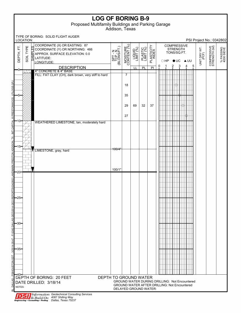
7
18
35
29
27
69 32 37
4" CONCRETE & 4" BASEFILL: FAT CLAY (CH), dark brown, very stiff to hard
WEATHERED LIMESTONE, tan, moderately hard
LIMESTONE, gray, hard 100/4"
100/1"
LL
UN
IT D
RY
WT
.(P
CF
)
CO
MP
RE
SS
IVE
ST
RE
NG
TH
(ts
f)
LOG OF BORING B-9
GROUND WATER DURING DRILLING: Not EncounteredGROUND WATER AFTER DRILLING: Not EncounteredDELAYED GROUND WATER:
Geotechnical Consulting Services4087 Shilling WayDallas, Texas 75237
DATE DRILLED: 3/18/14
PLA
ST
ICLI
MIT
(%
)
DEPTH TO GROUND WATER
PLA
ST
ICIT
YIN
DE
X
PL PI0 1 2 3 4 5
SA
MP
LES
NOTES:
HP
LIQ
UID
LIM
IT (
%) COMPRESSIVE
STRENGTHTONS/SQ.FT.
MO
IST
UR
EC
ON
TE
NT
(%
)
DE
PT
H,
FT
.
UUUCSO
IL T
YP
E
% P
AS
SIN
G#2
00 S
IEV
E
DESCRIPTION
DEPTH OF BORING: 20 FEET
COORDINATE (X) OR EASTING: 87COORDINATE (Y) OR NORTHING: 466
LATITUDE:LONGITUDE:
APPROX. SURFACE ELEVATION: 0.0
TYPE OF BORING: SOLID FLIGHT AUGERLOCATION: PSI Project No.: 0342802
Proposed Multifamily Buildings and Parking GarageAddison, Texas
SP
T -
NT
CP
- N
(BLO
WS
/FT
.)
BL_
DA
LLA
S -
PS
IHO
US
TO
N.G
DT
- 3
/25/
14
09:4
7 -
P:\0
342
DA
LLA
S G
EO
\201
4 G
EO
RE
PO
RT
S\0
3428
02 L
AN
DM
AR
K P
RE
ST
ON
AD
DIS
ON
, TX
- IM
T C
AP
ITA
L III
PR
ES
TO
NW
OO
D, L
P\L
OG
S.G
PJ
0
5
10
15
20
25
30
35
40

9
21 46 24 22
4" CONCRETE & 4" BASEFAT CLAY (CH), dark brown, hard
LEAN CLAY (CL), yellowish-brown, hard
WEATHERED LIMESTONE, tan, moderately hard
LIMESTONE, gray, hard
100/7"
100/4.5"
100/1.5"
100/1.5"
100/1"
LL
UN
IT D
RY
WT
.(P
CF
)
CO
MP
RE
SS
IVE
ST
RE
NG
TH
(ts
f)
LOG OF BORING B-10
GROUND WATER DURING DRILLING: Not EncounteredGROUND WATER AFTER DRILLING: Not EncounteredDELAYED GROUND WATER:
Geotechnical Consulting Services4087 Shilling WayDallas, Texas 75237
DATE DRILLED: 3/18/14
PLA
ST
ICLI
MIT
(%
)
DEPTH TO GROUND WATER
PLA
ST
ICIT
YIN
DE
X
PL PI0 1 2 3 4 5
SA
MP
LES
NOTES:
HP
LIQ
UID
LIM
IT (
%) COMPRESSIVE
STRENGTHTONS/SQ.FT.
MO
IST
UR
EC
ON
TE
NT
(%
)
DE
PT
H,
FT
.
UUUCSO
IL T
YP
E
% P
AS
SIN
G#2
00 S
IEV
E
DESCRIPTION
DEPTH OF BORING: 20 FEET
COORDINATE (X) OR EASTING: 87COORDINATE (Y) OR NORTHING: 335
LATITUDE:LONGITUDE:
APPROX. SURFACE ELEVATION: 0.0
TYPE OF BORING: SOLID FLIGHT AUGERLOCATION: PSI Project No.: 0342802
Proposed Multifamily Buildings and Parking GarageAddison, Texas
SP
T -
NT
CP
- N
(BLO
WS
/FT
.)
BL_
DA
LLA
S -
PS
IHO
US
TO
N.G
DT
- 3
/25/
14
09:4
7 -
P:\0
342
DA
LLA
S G
EO
\201
4 G
EO
RE
PO
RT
S\0
3428
02 L
AN
DM
AR
K P
RE
ST
ON
AD
DIS
ON
, TX
- IM
T C
AP
ITA
L III
PR
ES
TO
NW
OO
D, L
P\L
OG
S.G
PJ
0
5
10
15
20
25
30
35
40

9
22
16
17
15
50 22 28
6" CONCRETE & 4" BASELEAN CLAY (CL), yellowish-brown, hard
WEATHERED LIMESTONE, tan, moderately hard
LIMESTONE, gray, hard
37/12"
100/2.5"
100/1.5"
100/1"
LL
UN
IT D
RY
WT
.(P
CF
)
CO
MP
RE
SS
IVE
ST
RE
NG
TH
(ts
f)
LOG OF BORING B-11
GROUND WATER DURING DRILLING: Not EncounteredGROUND WATER AFTER DRILLING: Not EncounteredDELAYED GROUND WATER:
Geotechnical Consulting Services4087 Shilling WayDallas, Texas 75237
DATE DRILLED: 3/17/14
PLA
ST
ICLI
MIT
(%
)
DEPTH TO GROUND WATER
PLA
ST
ICIT
YIN
DE
X
PL PI0 1 2 3 4 5
SA
MP
LES
NOTES:
HP
LIQ
UID
LIM
IT (
%) COMPRESSIVE
STRENGTHTONS/SQ.FT.
MO
IST
UR
EC
ON
TE
NT
(%
)
DE
PT
H,
FT
.
UUUCSO
IL T
YP
E
% P
AS
SIN
G#2
00 S
IEV
E
DESCRIPTION
DEPTH OF BORING: 20 FEET
COORDINATE (X) OR EASTING: 50COORDINATE (Y) OR NORTHING: 123
LATITUDE:LONGITUDE:
APPROX. SURFACE ELEVATION: 0.0
TYPE OF BORING: SOLID FLIGHT AUGERLOCATION: PSI Project No.: 0342802
Proposed Multifamily Buildings and Parking GarageAddison, Texas
SP
T -
NT
CP
- N
(BLO
WS
/FT
.)
BL_
DA
LLA
S -
PS
IHO
US
TO
N.G
DT
- 3
/25/
14
09:4
7 -
P:\0
342
DA
LLA
S G
EO
\201
4 G
EO
RE
PO
RT
S\0
3428
02 L
AN
DM
AR
K P
RE
ST
ON
AD
DIS
ON
, TX
- IM
T C
AP
ITA
L III
PR
ES
TO
NW
OO
D, L
P\L
OG
S.G
PJ
0
5
10
15
20
25
30
35
40
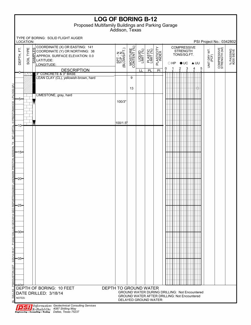
9
13
4" CONCRETE & 3" BASELEAN CLAY (CL), yellowish-brown, hard
LIMESTONE, gray, hard
100/3"
100/1.5"
LL
UN
IT D
RY
WT
.(P
CF
)
CO
MP
RE
SS
IVE
ST
RE
NG
TH
(ts
f)
LOG OF BORING B-12
GROUND WATER DURING DRILLING: Not EncounteredGROUND WATER AFTER DRILLING: Not EncounteredDELAYED GROUND WATER:
Geotechnical Consulting Services4087 Shilling WayDallas, Texas 75237
DATE DRILLED: 3/18/14
PLA
ST
ICLI
MIT
(%
)
DEPTH TO GROUND WATER
PLA
ST
ICIT
YIN
DE
X
PL PI0 1 2 3 4 5
SA
MP
LES
NOTES:
HP
LIQ
UID
LIM
IT (
%) COMPRESSIVE
STRENGTHTONS/SQ.FT.
MO
IST
UR
EC
ON
TE
NT
(%
)
DE
PT
H,
FT
.
UUUCSO
IL T
YP
E
% P
AS
SIN
G#2
00 S
IEV
E
DESCRIPTION
DEPTH OF BORING: 10 FEET
COORDINATE (X) OR EASTING: 141COORDINATE (Y) OR NORTHING: 38
LATITUDE:LONGITUDE:
APPROX. SURFACE ELEVATION: 0.0
TYPE OF BORING: SOLID FLIGHT AUGERLOCATION: PSI Project No.: 0342802
Proposed Multifamily Buildings and Parking GarageAddison, Texas
SP
T -
NT
CP
- N
(BLO
WS
/FT
.)
BL_
DA
LLA
S -
PS
IHO
US
TO
N.G
DT
- 3
/25/
14
09:4
7 -
P:\0
342
DA
LLA
S G
EO
\201
4 G
EO
RE
PO
RT
S\0
3428
02 L
AN
DM
AR
K P
RE
ST
ON
AD
DIS
ON
, TX
- IM
T C
AP
ITA
L III
PR
ES
TO
NW
OO
D, L
P\L
OG
S.G
PJ
0
5
10
15
20
25
30
35
40
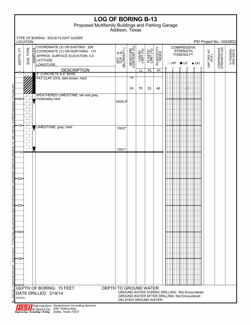
14
24 79 33 46
4" CONCRETE & 6" BASEFAT CLAY (CH), dark brown, hard
WEATHERED LIMESTONE, tan and gray,moderately hard
LIMESTONE, gray, hard
100/6.5"
100/3"
100/1"
LL
UN
IT D
RY
WT
.(P
CF
)
CO
MP
RE
SS
IVE
ST
RE
NG
TH
(ts
f)
LOG OF BORING B-13
GROUND WATER DURING DRILLING: Not EncounteredGROUND WATER AFTER DRILLING: Not EncounteredDELAYED GROUND WATER:
Geotechnical Consulting Services4087 Shilling WayDallas, Texas 75237
DATE DRILLED: 3/18/14
PLA
ST
ICLI
MIT
(%
)
DEPTH TO GROUND WATER
PLA
ST
ICIT
YIN
DE
X
PL PI0 1 2 3 4 5
SA
MP
LES
NOTES:
HP
LIQ
UID
LIM
IT (
%) COMPRESSIVE
STRENGTHTONS/SQ.FT.
MO
IST
UR
EC
ON
TE
NT
(%
)
DE
PT
H,
FT
.
UUUCSO
IL T
YP
E
% P
AS
SIN
G#2
00 S
IEV
E
DESCRIPTION
DEPTH OF BORING: 15 FEET
COORDINATE (X) OR EASTING: 206COORDINATE (Y) OR NORTHING: 131
LATITUDE:LONGITUDE:
APPROX. SURFACE ELEVATION: 0.0
TYPE OF BORING: SOLID FLIGHT AUGERLOCATION: PSI Project No.: 0342802
Proposed Multifamily Buildings and Parking GarageAddison, Texas
SP
T -
NT
CP
- N
(BLO
WS
/FT
.)
BL_
DA
LLA
S -
PS
IHO
US
TO
N.G
DT
- 3
/25/
14
09:4
7 -
P:\0
342
DA
LLA
S G
EO
\201
4 G
EO
RE
PO
RT
S\0
3428
02 L
AN
DM
AR
K P
RE
ST
ON
AD
DIS
ON
, TX
- IM
T C
AP
ITA
L III
PR
ES
TO
NW
OO
D, L
P\L
OG
S.G
PJ
0
5
10
15
20
25
30
35
40

CONSISTENCY N-VALUE
(Blows/Foot) SHEAR STRENGTH
(tsf) HAND PEN VALUE
(tsf)
Very Soft 0 TO 2 0 TO 0.125 0 TO 0.25
Soft 2 TO 4 0.125 TO 0.25 0.25 TO 0.5
Firm 4 TO 8 0.25 TO 0.5 0.5 TO 1.0
Stiff 8 TO 15 0.5 TO 1.0 1.0 TO 2.0
Very Stiff 15 TO 30 1.0 TO 2.0 2.0 TO 4.0
Hard >30 >2.0 OR 2.0+ >4.0 OR 4.0+
KEY TO TERMS AND SYMBOLS USED ON LOGS
CONSISTENCY OF COHESIVE SOILS
DESCRIPTION OF ROCK QUALITY
RQD
Very Poor (VPo) 0 TO 25
Poor (Po) 25 TO 50
Fair (F) 50 TO 75
Good (Gd) 75 TO 90
Excellent (ExInt) 90 TO 100
ROCK QUALITY
DESIGNATION (RQD)
DESCRIPTION OF RECOVERY
% CORE RECOVERY
Incompetent < 40
Competent 40 TO 70
Fairly Continuous 70 TO 90
Continuous 90 TO 100
RECOVERY
ROCK CLASSIFICATION
DENSITY (GRANULAR)
CONSISTENCY (COHESIVE)
THD (BLOWS/FT)
FIELD IDENTIFICATION
Very Loose (VLo) Very Soft (VSo) 0 TO 8 Core (height twice diameter) sags under own weight
Loose (Lo) Soft (So) 8 TO 20 Core can be pinched or imprinted easily with finger
Slightly Compact (SICmpt)
Stiff (St) 20 TO 40 Core can be imprinted with considerable pressure
Compact (Cmpt) Very Stiff (VSt) 40 TO 80 Core can only be imprinted slightly with fingers
Dense (De) Hard (H) 80 TO 5”/100 Core cannot be imprinted with fingers but can be penetrated with pencil
Very Dense (VDe) Very Hard (VH) 5”/100 to 0”/100
Core cannot be penetrated with pencil
SOIL DENSITY OR CONSISTENCY
DEGREE OF PLASTICITY
PLASTICITY INDEX (PI)
SWELL POTENTIAL
None or Slight 0 to 4 None
Low 4 to 20 Low
Medium 20 to 30 Medium
High 30 to 40 High
Very High >40 Very High
DEGREE OF PLASTICITY OF COHESIVE SOILS
MORHS’ SCALE
CHARACTERISTICS EXAMPLES APPROXIMATE THD
PEN TEST
5.5 to 10 Rock will scratch knife Sandstone, Chert, Schist, Granite, Gneiss, some Limestone
Very Hard (VH)
0” to 2”/100
3 to 5.5 Rock can be scratched with knife blade
Siltstone, Shale, Iron Deposits, most Limestone
Hard (H) 1” to
5”/100
1 to 3 Rock can be scratched with fingernail
Gypsum, Calcite, Evaporites, Chalk, some Shale
Soft (So) 4” to
6”/100
BEDROCK HARDNESS
DESCRIPTION CONDITION
Absence of moisture, dusty, dry to touch
DRY
Damp but no visible water MOIST
Visible free water WET
MOISTURE CONDITION OF COHESIVE SOILS
U.S. STANDARD SIEVE SIZE(S)
6" 3" 3/4" 4 10 200
GRAVEL SAND
152 76.2 19.1 4.76 2.0 0.42 0.074 0.002
GRAIN SIZE IN MM
SILT OR CLAY CLAYFINE
40
COARSE FINE COARSE MEDIUMCOBBLESBOULDERS
SAMPLER TYPES SOIL TYPES
APPARENT DESNITY
SPT (BLOWS/FT)
CALIFORNIA SAMPLER
(BLOWS/FT)
MODIFIED CA. SMAPLER
(BLOWS/FT)
RELATIVE DENSITY (%)
Very Loose 0 to 4 0 to 5 0 to 4 0 to 15
Loose 4 to 10 5 to 15 5 to 12 15 to 35
Medium Dense 10 to 30 15 to 40 12 to 35 35 to 65
Dense 30 to 50 40 to 70 35 to 60 65 to 85
Very Dense >50 >70 >60 85 to 100
RELATIVE DENSITY FOR GRANULAR SOILS
ABBREVIATIONS
CLASSIFICATION OF GRANULAR SOILS
PL – Plastic Limit
LL – Liquid Limit
WC – Percent Moisture
QP – Hand Penetrometer
QU – Unconfined Compression Test
UU – Unconsolidated Undrained Triaxial
Note: Plot Indicates Shear Strength as Obtained By Above Tests

IMT Prestonwood, Dallas, Texas GENERAL CONDITIONS BGO Project No. 13182 007000 - 1 26 March 2015
DOCUMENT 007000
GENERAL CONDITIONS
1.1 RELATED DOCUMENTS
A. Drawings and general provisions of the Contract, including General and Supplementary Conditions and Division 01 Specification Sections, apply to this Section.
1.2 GENERAL CONDITIONS
A. The "General Conditions of the Contract for Construction", AIA Document A201, Sixteenth Edition, 2007, Articles 1 through 15 inclusive, is a part of this Contract, and is available for review from the Architect. The General Conditions and all modifications listed hereinafter shall apply to all various subcontracts and sub-subcontractors.
B. Refer to Document 008000 for Supplementary Conditions.
END OF DOCUMENT

IMT Prestonwood, Dallas, Texas SUPPLEMENTARY CONDITIONS BGO Project No. 13182 008000 - 1 26 March 2015
DOCUMENT 008000
SUPPLEMENTARY CONDITIONS
1.1 SUPPLEMENTS
A. The following supplements modify, change, delete from or add to the "General Conditions of the Contract for Construction", AIA Document A201, Sixteenth Edition, 2007. Where any Article of the General
Conditions is modified or any Paragraph, Subparagraph or Clause thereof is modified or deleted by these supplements, the unaltered provision of the Article, Paragraph, Subparagraph or Clause shall remain in effect.
1.2 REFERENCE TO DIVISION 01
A. With regard to provisions of General Conditions related to project administrative or work-related requirements of the Contract, some of those paragraphs are modified or deleted from General Conditions, and are specified in Division 01, "General Requirements" of the Specifications.
ARTICLE 1 GENERAL PROVISIONS
Add the following new paragraphs:
1.1.9 MISCELLANEOUS DEFINITIONS
1.1.9.1 The term "Product" as used in these Contract Documents includes materials, systems, and equipment.
1.1.9.2 The term "provide" as used in this Project Manual means to furnish and install.
1.1.9.3 Tax Exempt: If the project is identified as tax exempt, “The Owner qualified for exemptions from the State
of Texas and local sales and use taxes pursuant to the provisions of the Texas Limited Sales, Excise and Use Tax Act. The Contractor shall not pay any such taxes which would otherwise be payable in connection with the performance of the Contract, but shall instead obtain an exemption by complying with the State Comptroller’s requirements. Exemption certificates will be furnished to the Contractor by the Owner.”
1.2 CORRELATION AND INTENT OF THE CONTRACT DOCUMENTS
Add the following new subparagraphs:
1.2.4 The inter-relation of the Project Manual, the Drawings and the schedules is as follows: The Project
Manual determines the quality, nature and setting of the several materials; the Drawings establish the quantities, dimensions and details; and the schedules give the location. The documents are to be considered as one and whatever is called for by any one shall be as binding as if called for by all.
1.2.5 Should the drawings disagree in themselves, or with the Project Manual, or if proprietary information
disagrees with performance requirements in either the Drawings or the Project Manual, the better quality or greater quantity of the Work or materials shall be estimated upon, and unless otherwise ordered by the Architect in writing, shall be performed or furnished. Should discrepancies or doubt occur, do not proceed with the Work without clarification from the Architect. Contractor shall request clarification in sufficient time to avoid delays and increases in the contract sum.
ARTICLE 3 CONTRACTOR
3.2 REVIEW OF CONTRACT DOCUMENTS AND FIELD CONDITIONS BY CONTRACTOR
Add following sentences to subparagraph 3.2.2:
3.2.2.1 ….If a dimensional discrepancy exists, Contractor shall take field measurements required for proper
fabrication and installation of work. Upon commencement of any item of work, Contractor shall be responsible for dimensions related to such item of Work and shall make any corrections necessary to make work properly fit at no additional cost to Owner.
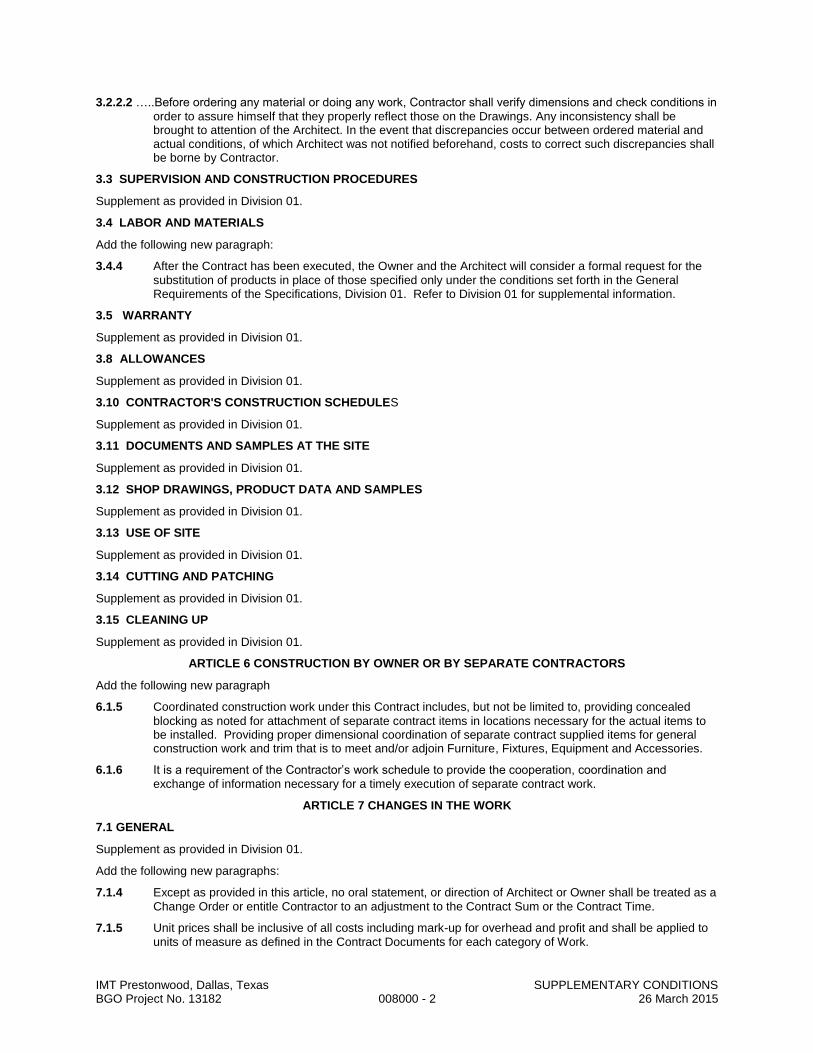
IMT Prestonwood, Dallas, Texas SUPPLEMENTARY CONDITIONS BGO Project No. 13182 008000 - 2 26 March 2015
3.2.2.2 …..Before ordering any material or doing any work, Contractor shall verify dimensions and check conditions in
order to assure himself that they properly reflect those on the Drawings. Any inconsistency shall be brought to attention of the Architect. In the event that discrepancies occur between ordered material and actual conditions, of which Architect was not notified beforehand, costs to correct such discrepancies shall be borne by Contractor.
3.3 SUPERVISION AND CONSTRUCTION PROCEDURES
Supplement as provided in Division 01.
3.4 LABOR AND MATERIALS
Add the following new paragraph:
3.4.4 After the Contract has been executed, the Owner and the Architect will consider a formal request for the
substitution of products in place of those specified only under the conditions set forth in the General Requirements of the Specifications, Division 01. Refer to Division 01 for supplemental information.
3.5 WARRANTY
Supplement as provided in Division 01.
3.8 ALLOWANCES
Supplement as provided in Division 01.
3.10 CONTRACTOR'S CONSTRUCTION SCHEDULES
Supplement as provided in Division 01.
3.11 DOCUMENTS AND SAMPLES AT THE SITE
Supplement as provided in Division 01.
3.12 SHOP DRAWINGS, PRODUCT DATA AND SAMPLES
Supplement as provided in Division 01.
3.13 USE OF SITE
Supplement as provided in Division 01.
3.14 CUTTING AND PATCHING
Supplement as provided in Division 01.
3.15 CLEANING UP
Supplement as provided in Division 01.
ARTICLE 6 CONSTRUCTION BY OWNER OR BY SEPARATE CONTRACTORS
Add the following new paragraph
6.1.5 Coordinated construction work under this Contract includes, but not be limited to, providing concealed
blocking as noted for attachment of separate contract items in locations necessary for the actual items to be installed. Providing proper dimensional coordination of separate contract supplied items for general construction work and trim that is to meet and/or adjoin Furniture, Fixtures, Equipment and Accessories.
6.1.6 It is a requirement of the Contractor’s work schedule to provide the cooperation, coordination and
exchange of information necessary for a timely execution of separate contract work.
ARTICLE 7 CHANGES IN THE WORK
7.1 GENERAL
Supplement as provided in Division 01.
Add the following new paragraphs:
7.1.4 Except as provided in this article, no oral statement, or direction of Architect or Owner shall be treated as a
Change Order or entitle Contractor to an adjustment to the Contract Sum or the Contract Time.
7.1.5 Unit prices shall be inclusive of all costs including mark-up for overhead and profit and shall be applied to
units of measure as defined in the Contract Documents for each category of Work.

IMT Prestonwood, Dallas, Texas SUPPLEMENTARY CONDITIONS BGO Project No. 13182 008000 - 3 26 March 2015
7.1.6 The allowance for the combined overhead and profit included in the total cost to the Owner shall be based on the following schedule:
7.1.6.1 For the Contractor, for Work performed by the Contractor’s own forces, 15 percent of the cost.
7.1.6.2 For the Contractor, for Work performed by the Contractor’s Subcontractor, 10 percent of the amount due the Subcontractor.
7.1.6.3 For each Subcontractor or Sub-subcontractor involved, for Work performed by that Subcontractor’s or Sub-subcontractor’s own forces, 15 percent of the cost.
7.1.6.4 For each Subcontractor, for Work performed by the Subcontractor’s Sub-subcontractors, 10 percent of the amount due the Sub-subcontractor.
7.1.6.5 Cost to which overhead and profit is to be applied shall be determined in accordance with Subparagraph 7.3.6.
7.1.6.6 In order to facilitate checking of quotations for extras or credits, all proposals, except those so minor that their propriety can be seen by inspection, shall be accompanied by a complete itemization of costs including labor, materials and Subcontracts. Labor and materials shall be itemized in the manner prescribed above. Where major cost items are Subcontracts, they shall be itemized also. In no case will a change involving over $2,000.00 be approved without such itemization.
ARTICLE 8 - TIME
8.3 DELAYS AND EXTENSIONS OF TIME
Add the following new paragraphs
8.3.4 Apart from extension of time, no payment or claim for damages shall be made to Contractor as compensation for damages for any ordinary delays or hindrances from any cause whatsoever in the progress of the Work, notwithstanding whether such delay be avoidable or unavoidable.
8.3.5 In order to claim an inclement weather delay day, Contractor must:
8.3.5.1 Document, in writing, that the weather on the particular day was of such nature (rain, wind, snow, ice, and
subsequent resultant effects) that it significantly impacted its ability to make progress on critical path work items. Inclement weather delay days will not be granted for weekends or holidays unless Contractor can demonstrate that it had been and intended to work on these days. Provide weather station/guage present on site and that all claims must be backed up by that instrument?
8.3.5.2 Submit such delay claims on a weekly basis, not more than 7 days following the day of occurrence.
8.3.5.3 Summarize the number of days claimed for the entire month accompanying each month’s application for
payment.
ARTICLE 9 PAYMENTS AND COMPLETION
9.2 SCHEDULE OF VALUES
Supplement as provided in Division 01.
9.3 APPLICATIONS FOR PAYMENT
Supplement as provided in Division 01.
Add the following new subparagraph:
9.3.4 Unless otherwise stated in the Owner-Contractor Agreement, the Owner will retain, until Final Payment, 10
percent of the amount due the Contractor on account of progress payments, payable 30 days after Substantial Completion and/or satisfactory evidence to the owner that all payments, bills, and claims have been paid.
Add following Sub-subparagraphs:
9.3.5 Monthly Applications for Payment shall include waivers of liens for all work included in previous months' application for payment. Waiver of Liens for subcontractors and materialmen shall be total amount paid prior to previous months' application for payment.
9.5 DECISIONS TO WITHHOLD CERTIFICATION
Add following Sub-subparagraph 9.5.1.8 to Subparagraph 9.5.1:

IMT Prestonwood, Dallas, Texas SUPPLEMENTARY CONDITIONS BGO Project No. 13182 008000 - 4 26 March 2015
9.5.1.8 Failure to submit written plan indicating action by Contractor to regain time schedule for completion of Work within Contract Time.
9.5.1.9 Failure to keep record documents current.
9.8 SUBSTANTIAL COMPLETION
Supplement as provided in Division 01.
9.10 FINAL COMPLETION AND FINAL PAYMENT
Add the following new paragraph
9.10.2.1 In addition to the items listed in 9.10.2, the Contractor shall deliver 4 sets of the following items to the
Owner before final payment will be made:
1. Other close-out submittals as specified in Division 01.
2. Project record documents as specified in Division 01.
3. Operations and maintenance data as specified in Division 01.
4. All warranties as required on specific products or portions of the Work, in format outlined in Division 01.
5. Spare parts, overages, and maintenance materials as outlined in Division 01 and described in the various technical sections.
6. Certificates of occupancy.
7. Copies of all inspection tags from authorities having jurisdiction.
8. Executed Certificate of Substantial Completion.
ARTICLE 11 INSURANCE AND BONDS
11.1 CONTRACTOR'S LIABILITY INSURANCE
Add the following new Sub-subparagraphs:
11.1.1.9 Liability insurance shall include all major divisions of coverage and be on a comprehensive basis including:
Worker’s compensation:
Comprehensive General Liability (including Premises – Operations; Independent Contractors; Protective; Products and Completed Operations; Broad Form Property Damage; Contractual):
Property Damage Liability Insurance shall include coverage for the following hazards as applicable:
X (Explosion), C (Collapse), U (Underground).
Comprehensive Automobile Liability
Provide in limits of liability as determined by the Owner.
11.1.1.10 Insurance certificate(s) shall specify Owner as the certificate holder and (except for Workers' Compensation) as an additional insured.
11.1.2 Add the following to the first sentence after the word “law”
“or as otherwise required by the Owner”
11.2 OWNER’S LIABILITY INSURANCE
Delete sub-paragraph in its entirety and substitute the following:
11.2.1 The Contractor shall purchase and maintain for the duration of the Contract a standard Owner’s and contractor’s Protective Liability Policy, as outlined in Paragraph 11.1, naming the Owner and Architect as insured. The Policy shall designate the Contractor and all sub-contractors. The Policy shall be endorsed to provide that the immunity of the Owner from suite shall not be a defense for the insurance company.
11.3 PROPERTY INSURANCE
In the first sentence, replace the word “Owner” with “Contractor”.
Add the following sub-paragraph 11.3.1.6:

IMT Prestonwood, Dallas, Texas SUPPLEMENTARY CONDITIONS BGO Project No. 13182 008000 - 5 26 March 2015
11.4.11 The Contractor shall furnish all insurance called for in paragraph “Property Insurance”. The roles of Owner and Contractor when related each to the other are reversed for the purpose of accomplishing Contractor insurance responsibility with the exception that Contractor shall remain responsible for determining need for any additional coverage for his interest.
ARTICLE 13 MISCELLANEOUS PROVISIONS
13.5 TESTS AND INSPECTIONS
Supplement as provided in Division 01.
END OF DOCUMENT
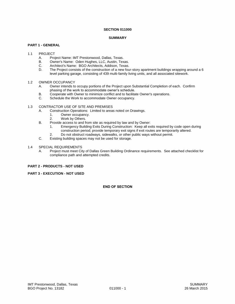
IMT Prestonwood, Dallas, Texas SUMMARY BGO Project No. 13182 011000 - 1 26 March 2015
SECTION 011000
SUMMARY
PART 1 - GENERAL
1.1 PROJECT A. Project Name: IMT Prestonwood, Dallas, Texas. B. Owner's Name: Oden Hughes, LLC, Austin, Texas. C. Architect's Name: BGO Architects, Addison, Texas. D. The Project consists of the construction of a new four-story apartment buildings wrapping around a 6
level parking garage, consisting of 439 multi-family living units, and all associated sitework.
1.2 OWNER OCCUPANCY A. Owner intends to occupy portions of the Project upon Substantial Completion of each. Confirm
phasing of the work to accommodate owner’s schedule. B. Cooperate with Owner to minimize conflict and to facilitate Owner's operations. C. Schedule the Work to accommodate Owner occupancy.
1.3 CONTRACTOR USE OF SITE AND PREMISES A. Construction Operations: Limited to areas noted on Drawings.
1. Owner occupancy. 2. Work by Others.
B. Provide access to and from site as required by law and by Owner: 1. Emergency Building Exits During Construction: Keep all exits required by code open during
construction period; provide temporary exit signs if exit routes are temporarily altered. 2. Do not obstruct roadways, sidewalks, or other public ways without permit.
C. Existing building spaces may not be used for storage.
1.4 SPECIAL REQUIREMENTS A. Project must meet City of Dallas Green Building Ordinance requirements. See attached checklist for
compliance path and attempted credits.
PART 2 - PRODUCTS - NOT USED
PART 3 - EXECUTION - NOT USED
END OF SECTION

for Homes
Project Team Leader:
Home Address (Street/City/State):
Project Description Adjusted Certification Thresholds
Building Type: # of stories: 4 Certified: 39.0 Gold: 69.0
# of Units: 438 Avg. Home Size Adjustment: -6.0 Silver: 54.0 Platinum: 84.0
Project Point Total Final Credit Category Point Totals
Prelim: Final: 9 ID: 0 SS: 4 EA: 4 EQ: 0
Certification Level LL: 0 WE: 0 MR: 1 AE: 0
Prelim: Final:
Date Most Recently Updated: Updated by: 60.5 5 9.0
Max Pts. Project
? Indicates that an Accountability Form is required. Available Y / Pts Maybe No Points
Innovation & Design Process (ID) (Minimum 0 ID Points Required) Max: 11 Y:8.5 M:0 Final: 0
1. Integrated Project Planning 8.5 0 01.1 Preliminary Rating Prereq. Y
Target performance tier:
1.2 Energy Expertise for MID-RISE Prereq. Y
1.3 Professional Credentialed with Respect to LEED for Homes 1 1 0 0
1.4 Design Charrette 1 1 0 0
1.5 Building Orientation for Solar Design (meet all of the following) 1 0 0 N 0
1.6 Trades Training for MID-RISE 1 1 0 0
2. Quality Management for Durability
2.1 Durability Planning (meet all of the following) Prereq.
Preliminary Rating
Silver
60.5 + 5 maybe pts
Mid-rise multi-family
Not Certified
Silver
Notes
please see ID 01-06 for details
LEED for Homes Mid-rise Project Checklist
Minimum Point Thresholds Not Met for Final Rating
Builder Name: Investors Management Trust Real Estate Group, Inc.
Matthew Para, Investors Management Trust Real Estate Group, Inc.
??? Arapaho Tollway, Dallas, Texas
a) Durability evaluation completed
c-i) Nonpaper-faced backer board in tub, shower, spa areas
b) Strategies developed to address durability issues
a) Glazing area on north/south walls 50% greater than on east/west walls c) At least 450 sq. ft. of south-facing roof area, oriented for solar applications
b) East-west axis is within 15 degrees of due east-west d) 90% of south-facing glazing is shaded in summer, unshaded in winter
d) Durability strategies incorporated into project documentation
e) Durability measures listed in durability inspection checklist
c-ii) No carpet in kitchen, bathroom, laundry, and spa areas
c-iii) No carpet within 3 ft of each entryway
c-iv) Install drain and drain pans in tank water heaters in/over living spaces; OR
c-v) Install drain and drain pans for clothes washers in/over living spaces; OR
no tank water heaters in/over living spaces
no clothes washers in/over living spaces
c-vi) Exhaust conventional clothes dryers directly to outdoors
c-vii) Install drain and drain pan for condensing clothes dryers
US Green Building Council Page 1 of 21 August, 2013

2.2 Durability Management (meet one of the following) Prereq.
2.3 Third-Party Durability Management Verification 3 3 0 0
3. Innovative or Regional Design
3.1 ? Innovation 1 (ruling #): 1 1 0 0
3.2 ? Innovation 2 (ruling #): 1 1 0 0
3.3 ? Innovation 3 (ruling #): 1 0.5 0 0
3.4 ? Innovation 4 (ruling #): 1 0 0 0
Location & Linkages (LL) (Minimum 0 LL Points Required) Max: 10 Y:9 M:0 Final: 0
1. LEED for Neighborhood Development 9 0 0
1 LEED for Neighborhood Development 10 0 0 N 0
2. Site Selection
2 ? Site Selection (meet all of the following) 2 2 0 0
3. Preferred Locations
3.1 Edge Development 1 0 0 N 0
OR 3.2 Infill 2 2 0 N 0
AND/OR 3.3 Brownfield Redevelopment for MID-RISE 1 0 0 N 0
4. Infrastructure
4 Existing Infrastructure 1 1 0 0
5. Community Resources / Transit
5.1 Basic Community Resources for MID-RISE (meet one of the following) 1 0 0 N 0
OR 5.2 Extensive Community Resources for MID-RISE (meet one of the following) 2 0 0 N 0
OR 5.3 Outstanding Community Resources for MID-RISE (meet one of the following) 3 3 0 0
6. Access to Open Space
6 Access to Open Space 1 1 0 0
Trusses
Notes
SS 07-02
WE2-15a
MR 1.4
Public Transit Exemplary Performance
Irrigation Exemplary Performance
Builder has a quality management process in place Builder conducted inspection using durability inspection checklist
a) Built above 100-year floodplain defined by FEMA
c) Not built within 100 ft of water, including wetlands
b) Not built on habitat for threatened or endangered species
d) Not built on land that was public parkland prior to acquisition
e) Not built on land with prime soils, unique soils, or soils of state significance
a) Within 1/4 mile of 4 basic community resources b) Within 1/2 mile of 7 basic community resources
a) Within 1/4 mile of 7 basic community resources b) Within 1/2 mile of 11 basic community resources
a) Within 1/4 mile of 11 basic community resources b) Within 1/2 mile of 14 basic community resource
a) Site meets criteria as "contaminated" by ASTM E1903-97 Phase II b) Site defined as "brownfield" by local, state, or federal government agency
US Green Building Council Page 2 of 21 August, 2013

Sustainable Sites (SS) (Minimum 5 SS Points Required) Max: 22 Y:12 M:3 Final: 4
1. Site Stewardship 12 3 4
1.1 Erosion Controls During Construction (meet all of the following) Prereq. Y
1.2 Minimize Disturbed Area for MID-RISE (meet appropriate requirements) 1 1 0 0
Where the site is not previously developed, meet all the following:
OR Where the site is previously developed, meet all the following:
OR
2. Landscaping
2.1 ? No Invasive Plants Prereq. Y
2.2 ? Basic Landscaping Design (meet all of the following) 1 1 0 0
AND/OR 2.3 ? Limit Conventional Turf for MID-RISE 2 1 1 1
Percentage of designed landscape softscape area that is turf
AND/OR 2.4 ? Drought-Tolerant Plants for MID-RISE 1 0 1 0
Percentage of installed plants that are drought-tolerant
OR 2.5 ? Reduce Overall Irrigation Demand by at Least 20% for MID-RISE 3 0 0 N 0
Percentage reduction in estimated irrigation water demand (calculate)
3. Reduce Local Heat Island Effects
3.1 ? Reduce Site Heat Island Effects for MID-RISE (meet one) 1 1 0 0
3.2 ? Reduce Roof Heat Island Effects for MID-RISE (meet one) 1 1 0 0
might achieve 20%
90%
points depend on SS2.3
Notes
Garage qualifies for this credit
30%
a) Stockpile and protect disturbed topsoil from erosion.
c) Protect sewer inlets, streams, and lakes with straw bales, silt fencing, etc.
b) Control the path and velocity of runoff with silt fencing or equivalent.
d) Provide swales to divert surface water from hillsides
e) Use tiers, erosion blankets, compost blankets, etc. on sloped areas.
b) Leave 40% of buildable lot area, not including area under roof, undisturbed
a) Develop tree / plant preservation plan with "no-disturbance" zones
c) Develop tree / plant preservation plan with "no-disturbance" zones AND
Rehabilitate lot; undo soil compaction and remove invasive plants AND
Meet the requirements of SS 2.2
d) Build on a lot to achieve a density of 40 units per acre.
a) Locate trees / plantings to provide shade for 50% of hardscapes b) Install light-colored, high-albedo materials for 50% of sidewalks, patios, and driveways
a) Install roof with high albedo materials on 75% of roof area c) Install combination of high albedo and vegetated roof
b) Install a vegetated roof for at least 50% of roof area
Both points in SS 2.3 are met ( ≤ 20% turf)
a) Any turf must be drought-tolerant.
c) Do not use turf in areas with slope of 25%
b) Do not use turf in densely shaded areas.
d) Add mulch or soil amendments as appropriate.
e) All compacted soil must be tilled to at least 6 inches.
US Green Building Council Page 3 of 21 August, 2013
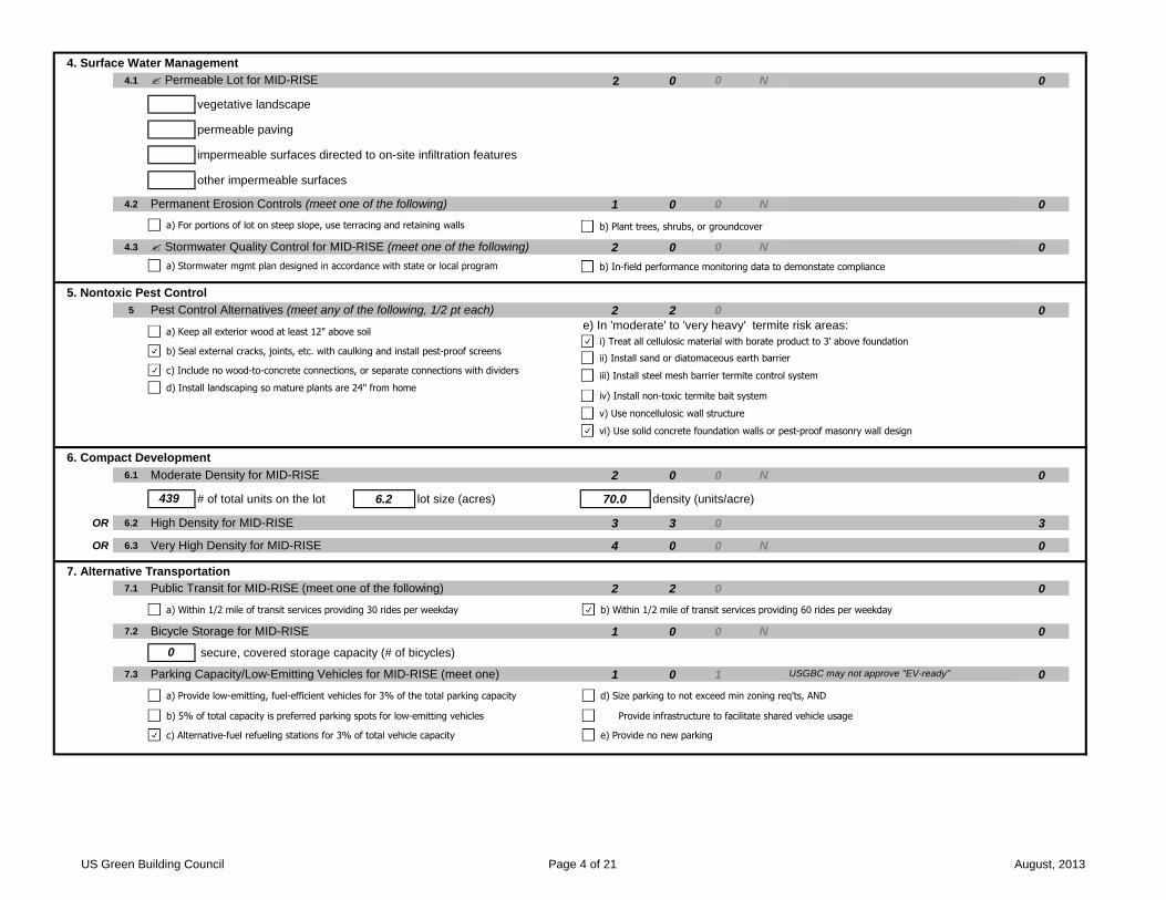
4. Surface Water Management
4.1 ? Permeable Lot for MID-RISE 2 0 0 N 0
vegetative landscape
permeable paving
impermeable surfaces directed to on-site infiltration features
other impermeable surfaces
4.2 Permanent Erosion Controls (meet one of the following) 1 0 0 N 0
4.3 ? Stormwater Quality Control for MID-RISE (meet one of the following) 2 0 0 N 0
5. Nontoxic Pest Control
5 Pest Control Alternatives (meet any of the following, 1/2 pt each) 2 2 0 0
e) In 'moderate' to 'very heavy' termite risk areas:
6. Compact Development
6.1 Moderate Density for MID-RISE 2 0 0 N 0
# of total units on the lot 6.2 lot size (acres) 70.0 density (units/acre)
OR 6.2 High Density for MID-RISE 3 3 0 3
OR 6.3 Very High Density for MID-RISE 4 0 0 N 0
7. Alternative Transportation
7.1 Public Transit for MID-RISE (meet one of the following) 2 2 0 0
7.2 Bicycle Storage for MID-RISE 1 0 0 N 0
secure, covered storage capacity (# of bicycles)
7.3 Parking Capacity/Low-Emitting Vehicles for MID-RISE (meet one) 1 0 1 0USGBC may not approve "EV-ready"
0
439
a) For portions of lot on steep slope, use terracing and retaining walls b) Plant trees, shrubs, or groundcover
a) Keep all exterior wood at least 12" above soil
c) Include no wood-to-concrete connections, or separate connections with dividers
b) Seal external cracks, joints, etc. with caulking and install pest-proof screens
d) Install landscaping so mature plants are 24" from home
i) Treat all cellulosic material with borate product to 3' above foundation
ii) Install sand or diatomaceous earth barrier
iii) Install steel mesh barrier termite control system
iv) Install non-toxic termite bait system
v) Use noncellulosic wall structure
vi) Use solid concrete foundation walls or pest-proof masonry wall design
a) Within 1/2 mile of transit services providing 30 rides per weekday b) Within 1/2 mile of transit services providing 60 rides per weekday
a) Provide low-emitting, fuel-efficient vehicles for 3% of the total parking capacity
c) Alternative-fuel refueling stations for 3% of total vehicle capacity
b) 5% of total capacity is preferred parking spots for low-emitting vehicles
d) Size parking to not exceed min zoning req'ts, AND
Provide infrastructure to facilitate shared vehicle usage
e) Provide no new parking
a) Stormwater mgmt plan designed in accordance with state or local program b) In-field performance monitoring data to demonstate compliance
US Green Building Council Page 4 of 21 August, 2013

Water Efficiency (WE) (Minimum 3 WE Points Required) Max: 15 Y:8 M:1 Final: 0
1. Water Reuse 8 1 0
1 ? Water Reuse for MID-RISE 5 0 0 N 0
of total water demand offset by water reuse strategies
(mark any/all strategies adopted)
2. Irrigation System
2.1 ? High-Efficiency Irrigation System for MID-RISE (meet any, 0.5 pt each) 2 2 0 0
OR 2.2 ? Reduce Overall Irrigation Demand by at Least 45% for MID-RISE 2 0 0 N 0
Percentage reduction in estimated irrigation water demand (see SS 2.5)
3. Indoor Water Use
3.1 High-Efficiency Fixtures and Fittings (meet any of the following, 1 pt each) 3 1 0 0
3.2 Very High-Efficiency Fixtures and Fittings (meet any, 2 pts each) 6 4 0 0
3.3 Water Efficient Appliances for MID-RISE (meet any of following, 1 pt each) 2 1 1 0
Notes
0%
a) Irrigation system designed by EPA Water Sense certified professional
c) Install central shut-off valve
b) Irrigation system with head-to-head coverage
d) Install submeter for the irrigation system
e) Use drip irrigation for 50% of planting beds
f) Create separate zones for each type of bedding
g) Install timer or controller for each watering zone
h) Install pressure-regulating devices
i) High-efficiency nozzles with distribution uniformity of at least 0.70.
j) Install check valves in heads
k) Install moisture sensor or rain delay controller
a) Average flow rate of lavatory faucets is ≤ 2.00 gpm c) Average flow rate for all toilets is ≤ 1.30 gpf; OR
b) Average flow rate for all showers is ≤ 2.00 gpm per stall Toilets are dual-flush; OR
Toilets meet the EPA Water Sense specification
a) Average flow rate of lavatory faucets is ≤ 1.50 gpm; OR b) Average flow rate for all showers ≤ 1.75 gpm per stall
Lavatory faucets meet the EPA Water Sense specification c) Average flow rate for all toilets is ≤ 1.10 gpf
l) Third-party inspection of irrigation system
a) Water-efficient clothes washers with MEF ≥ 2.0 and WF < 5.5 b) ENERGY STAR dishwasher(s) that use ≤ 6.0 gallons per cycle
Rainwater harvesting
Graywater reuse
Municipal recycled water
US Green Building Council Page 5 of 21 August, 2013
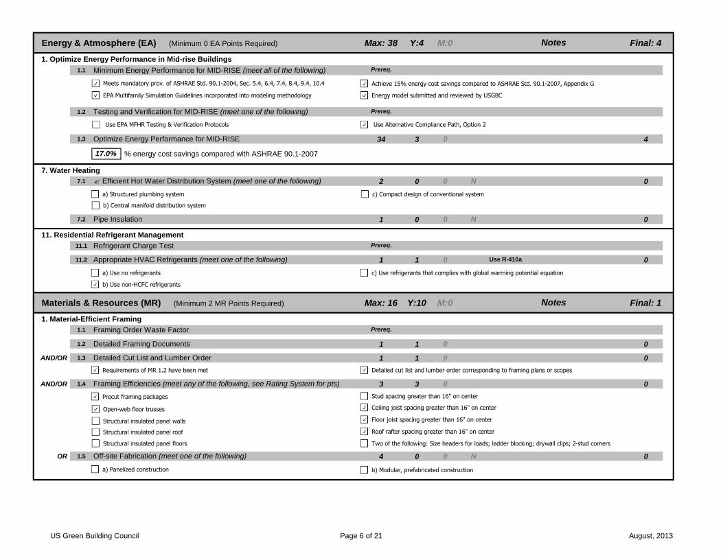
Energy & Atmosphere (EA) (Minimum 0 EA Points Required) Max: 38 Y:4 M:0 Final: 4
1. Optimize Energy Performance in Mid-rise Buildings 4.0 0.0 4.0
1.1 Minimum Energy Performance for MID-RISE (meet all of the following) Prereq.
1.2 Testing and Verification for MID-RISE (meet one of the following) Prereq.
1.3 Optimize Energy Performance for MID-RISE 34 3 0 4
% energy cost savings compared with ASHRAE 90.1-2007
7. Water Heating
7.1 ? Efficient Hot Water Distribution System (meet one of the following) 2 0 0 N 0
7.2 Pipe Insulation 1 0 0 N 0
11. Residential Refrigerant Management
11.1 Refrigerant Charge Test Prereq.
11.2 Appropriate HVAC Refrigerants (meet one of the following) 1 1 0 0
Materials & Resources (MR) (Minimum 2 MR Points Required) Max: 16 Y:10 M:0 Final: 1
1. Material-Efficient Framing 10 0 1
1.1 Framing Order Waste Factor Prereq.
1.2 Detailed Framing Documents 1 1 0 0
AND/OR 1.3 Detailed Cut List and Lumber Order 1 1 0 0
AND/OR 1.4 Framing Efficiencies (meet any of the following, see Rating System for pts) 3 3 0 0
OR 1.5 Off-site Fabrication (meet one of the following) 4 0 0 N 0
Notes
Notes
Use R-410a
17.0%
a) Structured plumbing system c) Compact design of conventional system
b) Central manifold distribution system
a) Use no refrigerants c) Use refrigerants that complies with global warming potential equation
b) Use non-HCFC refrigerants
Precut framing packages
Structural insulated panel walls
Open-web floor trusses
Structural insulated panel roof
Stud spacing greater than 16" on center
Structural insulated panel floors
Ceiling joist spacing greater than 16" on center
Roof rafter spacing greater than 16" on center
Floor joist spacing greater than 16" on center
Two of the following: Size headers for loads; ladder blocking; drywall clips; 2-stud corners
a) Panelized construction b) Modular, prefabricated construction
Requirements of MR 1.2 have been met Detailed cut list and lumber order corresponding to framing plans or scopes
Meets mandatory prov. of ASHRAE Std. 90.1-2004, Sec. 5.4, 6.4, 7.4, 8.4, 9.4, 10.4 Achieve 15% energy cost savings compared to ASHRAE Std. 90.1-2007, Appendix G
EPA Multifamily Simulation Guidelines incorporated into modeling methodology Energy model submitted and reviewed by USGBC
Use EPA MFHR Testing & Verification Protocols Use Alternative Compliance Path, Option 2
US Green Building Council Page 6 of 21 August, 2013
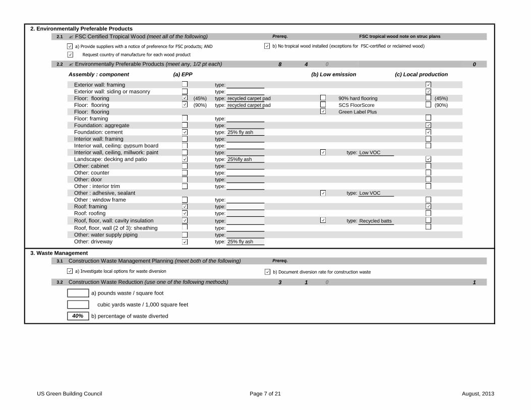
2. Environmentally Preferable Products
2.1 ? FSC Certified Tropical Wood (meet all of the following) Prereq.
2.2 ? Environmentally Preferable Products (meet any, 1/2 pt each) 8 4 0 0
Assembly : component (a) EPP (b) Low emission (c) Local production
Exterior wall: framing type:
Exterior wall: siding or masonry type:
Floor: flooring (45%) type: recycled carpet pad 90% hard flooring (45%)
Floor: flooring (90%) type: recycled carpet pad SCS FloorScore (90%)
Floor: flooring Green Label Plus
Floor: framing type:
Foundation: aggregate type:
Foundation: cement type: 25% fly ash
Interior wall: framing type:
Interior wall, ceiling: gypsum board type:
Interior wall, ceiling, millwork: paint type: type: Low VOC
Landscape: decking and patio type: 25%fly ash
Other: cabinet type:
Other: counter type:
Other: door type:
Other : interior trim type:
Other : adhesive, sealant type: Low VOC
Other : window frame type:
Roof: framing type:
Roof: roofing type:
Roof, floor, wall: cavity insulation type: type: Recycled batts
Roof, floor, wall (2 of 3): sheathing type:
Other: water supply piping type:
Other: driveway type: 25% fly ash
3. Waste Management
3.1 Construction Waste Management Planning (meet both of the following) Prereq.
3.2 Construction Waste Reduction (use one of the following methods) 3 1 0 1
a) pounds waste / square foot 0
cubic yards waste / 1,000 square feet 0
b) percentage of waste diverted 140%
FSC tropical wood note on struc plans
a) Provide suppliers with a notice of preference for FSC products; AND b) No tropical wood installed (exceptions for FSC-certified or reclaimed wood)
a) Investigate local options for waste diversion b) Document diversion rate for construction waste
Request country of manufacture for each wood product
US Green Building Council Page 7 of 21 August, 2013

Indoor Environmental Quality (EQ) (Minimum 3 EQ Points Required) Max: 21 Y:7 M:1 Final: 0
2. Combustion Venting
2 Basic Combustion Venting Measures for MID-RISE (meet all the following) Prereq.
3. Moisture Control
3 Moisture Load Control (meet one of the following) 1 0 0 N 0
4. Outdoor Air Ventilation
4.1 ? Basic Outdoor Air Ventilation for MID-RISE (meet all of the following) Prereq.
4.2 Enhanced Outdoor Air Ventilation for MID-RISE 2 0 0 N 0
4.3 Third-Party Performance Testing for MID-RISE 1 0 0 N 0
5. Local Exhaust
5.1 ? Basic Local Exhaust for MID-RISE (meet all of the following) Prereq.
5.2 Enhanced Local Exhaust (meet one of the following) 1 1 0
5.3 Third-Party Performance Testing for MID-RISE 1 0 0 N 0
Notes
ENERGY STAR bath fans
a) no unvented combustion appliances
c) no fireplace installed, OR
b) carbon monoxide monitors on each floor of each unit
d) space, water heating equipment designed with closed combustion; OR
space and water heating equipment located in detached or open-air facility; OR
space and water heating equipment has power-vented exhaust; OR
no space- or water-heating equipment with combustion
b) HVAC system equipped with additional dehumidification mode
a) ASHRAE 62.2-2007 met for all in-unit spaces
a) In-unit bathrooms and kitchens meet ASHRAE 62.2-2007 air flow requirements d) ENERGY STAR labeled bathroom exhaust fans OR
b) Fans and ducts designed and installed to ASHRAE Std. 62.2 Multi-port bathroom exhaust systems installed
a) Occupancy sensor c) Automatic timer tied to switch to operate fan for 20+ minutes post-occupancy
b) Automatic humidistat controller d) Continuously operating exhaust fan
a) Additional dehumidification system
b) ASHRAE 62.1-2007, Sections 4 through 7 met for residential-associated spaces
c) Air exhausted to outdoors through roof or outside wall
all fireplaces and woodstoves have doors
e) Common bathrooms and kitchens meet ASHRAE 62.1-2007 air flow requirements
US Green Building Council Page 8 of 21 August, 2013
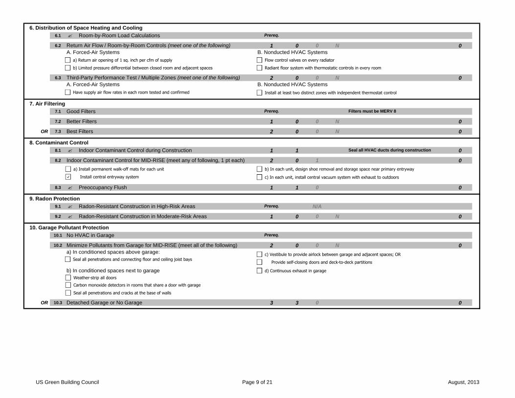
6. Distribution of Space Heating and Cooling
6.1 ? Room-by-Room Load Calculations Prereq.
6.2 Return Air Flow / Room-by-Room Controls (meet one of the following) 1 0 0 N 0
A. Forced-Air Systems B. Nonducted HVAC Systems
6.3 Third-Party Performance Test / Multiple Zones (meet one of the following) 2 0 0 N 0
A. Forced-Air Systems B. Nonducted HVAC Systems
7. Air Filtering
7.1 Good Filters Prereq.
7.2 Better Filters 1 0 0 N 0
OR 7.3 Best Filters 2 0 0 N 0
8. Contaminant Control
8.1 ? Indoor Contaminant Control during Construction 1 1 0
8.2 Indoor Contaminant Control for MID-RISE (meet any of following, 1 pt each) 2 0 1 0
8.3 ? Preoccupancy Flush 1 1 0 0
9. Radon Protection
9.1 ? Radon-Resistant Construction in High-Risk Areas Prereq. N/A
9.2 ? Radon-Resistant Construction in Moderate-Risk Areas 1 0 0 N 0
10. Garage Pollutant Protection
10.1 No HVAC in Garage Prereq.
10.2 Minimize Pollutants from Garage for MID-RISE (meet all of the following) 2 0 0 N 0
a) In conditioned spaces above garage:
b) In conditioned spaces next to garage
OR 10.3 Detached Garage or No Garage 3 3 0 0
Seal all HVAC ducts during construction
Filters must be MERV 8
b) Limited pressure differential between closed room and adjacent spaces
a) Return air opening of 1 sq. inch per cfm of supply Flow control valves on every radiator
Have supply air flow rates in each room tested and confirmed Install at least two distinct zones with independent thermostat control
a) Install permanent walk-off mats for each unit
c) In each unit, install central vacuum system with exhaust to outdoors
b) In each unit, design shoe removal and storage space near primary entryway
Seal all penetrations and connecting floor and ceiling joist bays
Weather-strip all doors
Carbon monoxide detectors in rooms that share a door with garage
Seal all penetrations and cracks at the base of walls
Provide self-closing doors and deck-to-deck partitions
Radiant floor system with thermostatic controls in every room
Install central entryway system
c) Vestibule to provide airlock between garage and adjacent spaces; OR
d) Continuous exhaust in garage
US Green Building Council Page 9 of 21 August, 2013

11. Environmental Tobacco Smoke Control
11 Env. Tobacco Smoke Reduction for MID-RISE (meet part (a) or (b) below) 1 1 0 0
a) Reduce smoke exposure and transfer (1/2 point) b) Prohibit smoking throughout the building (1 points)
12. Compartmentalization of Units
12.1 Compartmentalization of Units (meet both of the following) Prereq.
12.2 Enhanced Compartmentalization of Units 1 0 0 N 0
Awareness & Education (AE) (Minimum 0 AE Points Required) Max: 3 Y:2 M:0 Final: 0
1. Education of the Homeowner or Tenant 2 0 0
1.1 ? Basic Operations Training (meet both of the following) Prereq.
1.2 ? Enhanced Training 1 0 0 N 0
1.3 Public Awareness (meet three of the following) 1 1 0 0
2. Education of the Building Manager
2 ? Education of the Building Manager (meet both of the following) 1 1 0 0
Notes
a) Operations and training manual b) One-hour walkthrough with occupant(s)
b) Website about features and benefits of LEED homes
c) Newspaper article on the project a) Open house on at least four weekends
d) Display LEED signage on the exterior of the home
a) Operations and training manual b) One-hour walkthrough with building manager
Prohibit smoking in all common areas
Any exterior smoking areas are > 25 ft from entries, air intakes, windows
Prohibit on-property smoking within 25 feet of entries, intakes, windows
Prohibit smoking within living units
Prohibit smoking in all common areas of the building
Any exterior smoking areas are > 25 ft from entries, air intakes, windows
Prohibitions communicated through lease agreements, CC&Rs, signage Prohibitions communicated through lease agreements, CC&Rs, signage
a) Air-seal and/or weather-strip all walls, chases, doors, windows, etc. b) Demonstrate minimal leakage of 0.30 CFM50 per square foot of enclosure
US Green Building Council Page 10 of 21 August, 2013

IMT Prestonwood, Dallas, Texas PRICE AND PAYMENT PROCEDURES BGO Project No. 13182 012000 - 1 26 March 2015
SECTION 012000
PRICE AND PAYMENT PROCEDURES
PART 1 GENERAL
1.1 SECTION INCLUDES A. Procedures for preparation and submittal of applications for progress payments. B. Documentation of changes in Contract Price and Contract Time. C. Change procedures. D. Correlation of Contractor submittals based on changes. E. Procedures for preparation and submittal of application for final payment.
1.2 SCHEDULE OF VALUES A. Electronic media printout including equivalent information will be considered in lieu of standard form
specified; submit sample to Architect for approval. B. Forms filled out by hand will not be accepted. C. Submit Schedule of Values in duplicate within 15 days after date of Owner-Contractor Agreement.
1.3 APPLICATIONS FOR PROGRESS PAYMENTS A. Payment Period: Submit at intervals stipulated in the Agreement. B. Electronic media printout including equivalent information will be considered in lieu of standard form
specified; submit sample to Architect for approval. C. Forms filled out by hand will not be accepted. D. For each item, provide a column for listing each of the following:
1. Item Number. 2. Description of work. 3. Scheduled Values. 4. Previous Applications. 5. Work in Place and Stored Materials under this Application. 6. Authorized Change Orders. 7. Total Completed and Stored to Date of Application. 8. Percentage of Completion. 9. Balance to Finish. 10. Retainage.
E. Execute certification by signature of authorized officer. F. Use data from approved Schedule of Values. Provide dollar value in each column for each line item for
portion of work performed and for stored products. G. List each authorized Change Order as a separate line item, listing Change Order number and dollar
amount as for an original item of Work. H. Submit three copies of each Application for Payment. I. Include the following with the application:
1. Transmittal letter as specified for Submittals in Section 013000. 2. Construction progress schedule, revised and current as specified in Section 013000. 3. Current construction photographs specified in Section 013000. 4. Project record documents as specified in Section 017800, for review by Owner which will be
returned to the Contractor. 5. Affidavits attesting to off-site stored products.
J. When Architect requires substantiating information, submit data justifying dollar amounts in question. Provide one copy of data with cover letter for each copy of submittal. Show application number and date, and line item by number and description.

IMT Prestonwood, Dallas, Texas PRICE AND PAYMENT PROCEDURES BGO Project No. 13182 012000 - 2 26 March 2015
1.4 MODIFICATION PROCEDURES A. For minor changes not involving an adjustment to the Contract Price or Contract Time, Architect will
issue instructions directly to Contractor. B. For other required changes, Architect will issue a document signed by Owner instructing Contractor to
proceed with the change, for subsequent inclusion in a Change Order. 1. The document will describe the required changes and will designate method of determining any
change in Contract Price or Contract Time. 2. Promptly execute the change.
C. For changes for which advance pricing is desired, Architect will issue a document that includes a detailed description of a proposed change with supplementary or revised drawings and specifications, a change in Contract Time for executing the change with a stipulation of any overtime work required and the period of time during which the requested price will be considered valid. Contractor shall prepare and submit a fixed price quotation within 14 days.
D. Computation of Change in Contract Amount: As specified in the Agreement and Conditions of the Contract. 1. For change requested by Architect for work falling under a fixed price contract, the amount will
be based on Contractor's price quotation. 2. For change requested by Contractor, the amount will be based on the Contractor's request for a
Change Order as approved by Architect. 3. For pre-determined unit prices and quantities, the amount will based on the fixed unit prices. 4. For change ordered by Architect without a quotation from Contractor, the amount will be
determined by Architect based on the Contractor's substantiation of costs as specified for Time and Material work.
E. Substantiation of Costs: Provide full information required for evaluation. 1. On request, provide following data:
a. Quantities of products, labor, and equipment. b. Taxes, insurance, and bonds. c. Overhead and profit. d. Justification for any change in Contract Time. e. Credit for deletions from Contract, similarly documented.
2. Support each claim for additional costs with additional information: a. Origin and date of claim. b. Dates and times work was performed, and by whom. c. Time records and wage rates paid. d. Invoices and receipts for products, equipment, and subcontracts, similarly documented.
3. For Time and Material work, submit itemized account and supporting data after completion of change, within time limits indicated in the Conditions of the Contract.
F. Execution of Change Orders: Architect will issue Change Orders for signatures of parties as provided in the Conditions of the Contract.
G. After execution of Change Order, promptly revise Schedule of Values and Application for Payment forms to record each authorized Change Order as a separate line item and adjust the Contract Price.
H. Promptly revise progress schedules to reflect any change in Contract Time, revise sub-schedules to adjust times for other items of work affected by the change, and resubmit.
I. Promptly enter changes in Project Record Documents.
1.5 APPLICATION FOR FINAL PAYMENT A. Prepare Application for Final Payment as specified for progress payments, identifying total adjusted
Contract Price, previous payments, and sum remaining due. B. Application for Final Payment will not be considered until the following have been accomplished:
END OF SECTION

IMT Prestonwood, Dallas, Texas ALLOWANCES BGO Project No. 13182 012100 - 1 26 March 2015
SECTION 012100
ALLOWANCES
PART 1 GENERAL
1.1 SECTION INCLUDES A. Cash allowances. B. Contingency allowance. C. Inspecting and testing allowances. D. Payment and modification procedures relating to allowances.
1.2 CASH ALLOWANCES A. Costs Included in Cash Allowances: Cost of product to Contractor or subcontractor, less applicable
trade discounts , less cost of delivery to site , less applicable taxes . B. Costs Not Included in Cash Allowances: Product delivery to site and handling at the site, including
unloading, uncrating, and storage; protection of products from elements and from damage; and labor for installation and finishing.
C. Architect Responsibilities: 1. Consult with Contractor for consideration and selection of products , suppliers , and installers. 2. Select products in consultation with Owner and transmit decision to Contractor. 3. Prepare Change Order.
D. Contractor Responsibilities: 1. Assist Architect in selection of products , suppliers , and installers. 2. Obtain proposals from suppliers and installers and offer recommendations. 3. On notification of which products have been selected, execute purchase agreement with
designated supplier and installer. 4. Arrange for and process shop drawings, product data, and samples. Arrange for delivery. 5. Promptly inspect products upon delivery for completeness, damage, and defects. Submit
claims for transportation damage. E. Differences in costs will be adjusted by Change Order.
1.3 CONTINGENCY ALLOWANCE A. Contractor's costs for products, delivery, installation, labor, insurance, payroll, taxes, bonding,
equipment rental, overhead and profit will be included in Change Orders authorizing expenditure of funds from this Contingency Allowance.
B. Funds will be drawn from the Contingency Allowance only by Change Order. C. At closeout of Contract, funds remaining in Contingency Allowance will be credited to Owner by
Change Order.
1.4 INSPECTING AND TESTING ALLOWANCES A. Costs Included in Inspecting and Testing Allowances: Cost of engaging an inspecting or testing
agency; execution of inspecting and tests; and reporting results. B. Costs Not Included in the Inspecting and Testing Allowances:
1. Costs of incidental labor and facilities required to assist inspecting or testing agency. 2. Costs of testing services used by Contractor separate from Contract Document requirements. 3. Costs of retesting upon failure of previous tests as determined by Architect.
C. Payment Procedures: 1. Submit one copy of the inspecting or testing firm's invoice with next application for payment. 2. Pay invoice on approval by Architect.
D. Differences in cost will be adjusted by Change Order.
1.5 ALLOWANCES SCHEDULE A. To be determined.
PART 2 PRODUCTS - NOT USED
PART 3 EXECUTION - NOT USED
END OF SECTION
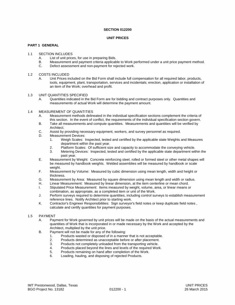
IMT Prestonwood, Dallas, Texas UNIT PRICES BGO Project No. 13182 012200 - 1 26 March 2015
SECTION 012200
UNIT PRICES
PART 1 GENERAL
1.1 SECTION INCLUDES A. List of unit prices, for use in preparing Bids. B. Measurement and payment criteria applicable to Work performed under a unit price payment method. C. Defect assessment and non-payment for rejected work.
1.2 COSTS INCLUDED A. Unit Prices included on the Bid Form shall include full compensation for all required labor, products,
tools, equipment, plant, transportation, services and incidentals; erection, application or installation of an item of the Work; overhead and profit.
1.3 UNIT QUANTITIES SPECIFIED A. Quantities indicated in the Bid Form are for bidding and contract purposes only. Quantities and
measurements of actual Work will determine the payment amount.
1.4 MEASUREMENT OF QUANTITIES A. Measurement methods delineated in the individual specification sections complement the criteria of
this section. In the event of conflict, the requirements of the individual specification section govern. B. Take all measurements and compute quantities. Measurements and quantities will be verified by
Architect. C. Assist by providing necessary equipment, workers, and survey personnel as required. D. Measurement Devices:
1. Weigh Scales: Inspected, tested and certified by the applicable state Weights and Measures department within the past year.
2. Platform Scales: Of sufficient size and capacity to accommodate the conveying vehicle. 3. Metering Devices: Inspected, tested and certified by the applicable state department within the
past year. E. Measurement by Weight: Concrete reinforcing steel, rolled or formed steel or other metal shapes will
be measured by handbook weights. Welded assemblies will be measured by handbook or scale weight.
F. Measurement by Volume: Measured by cubic dimension using mean length, width and height or thickness.
G. Measurement by Area: Measured by square dimension using mean length and width or radius. H. Linear Measurement: Measured by linear dimension, at the item centerline or mean chord. I. Stipulated Price Measurement: Items measured by weight, volume, area, or linear means or
combination, as appropriate, as a completed item or unit of the Work. J. Perform surveys required to determine quantities, including control surveys to establish measurement
reference lines. Notify Architect prior to starting work. K. Contractor's Engineer Responsibilities: Sign surveyor's field notes or keep duplicate field notes ,
calculate and certify quantities for payment purposes.
1.5 PAYMENT A. Payment for Work governed by unit prices will be made on the basis of the actual measurements and
quantities of Work that is incorporated in or made necessary by the Work and accepted by the Architect, multiplied by the unit price.
B. Payment will not be made for any of the following: 1. Products wasted or disposed of in a manner that is not acceptable. 2. Products determined as unacceptable before or after placement. 3. Products not completely unloaded from the transporting vehicle. 4. Products placed beyond the lines and levels of the required Work. 5. Products remaining on hand after completion of the Work. 6. Loading, hauling, and disposing of rejected Products.
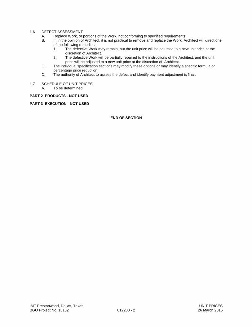
IMT Prestonwood, Dallas, Texas UNIT PRICES BGO Project No. 13182 012200 - 2 26 March 2015
1.6 DEFECT ASSESSMENT A. Replace Work, or portions of the Work, not conforming to specified requirements. B. If, in the opinion of Architect, it is not practical to remove and replace the Work, Architect will direct one
of the following remedies: 1. The defective Work may remain, but the unit price will be adjusted to a new unit price at the
discretion of Architect. 2. The defective Work will be partially repaired to the instructions of the Architect, and the unit
price will be adjusted to a new unit price at the discretion of Architect. C. The individual specification sections may modify these options or may identify a specific formula or
percentage price reduction. D. The authority of Architect to assess the defect and identify payment adjustment is final.
1.7 SCHEDULE OF UNIT PRICES A. To be determined.
PART 2 PRODUCTS - NOT USED
PART 3 EXECUTION - NOT USED
END OF SECTION
IMT Prestonwood, Dallas, Texas ADMINISTRATIVE REQUIREMENTS BGO Project No. 13182 013000 - 1 26 March 2015
SECTION 013000
ADMINISTRATIVE REQUIREMENTS
PART 1 GENERAL
1.1 SECTION INCLUDES A. Electronic document submittal service. B. Preconstruction meeting. C. Progress meetings. D. Construction progress schedule. E. Progress photographs. F. Submittals for review, information, and project closeout. G. Number of copies of submittals. H. Submittal procedures.
1.2 RELATED REQUIREMENTS A. Section 011000 - Summary: Work covered by each contract, occupancy, . B. Section 017000 - Execution and Closeout Requirements: Additional coordination requirements. C. Section 017800 - Closeout Submittals: Project record documents.
PART 2 PRODUCTS - NOT USED
PART 3 EXECUTION
3.1 ELECTRONIC DOCUMENT SUBMITTAL SERVICE A. All documents transmitted for purposes of administration of the contract are to be in electronic (PDF)
format and transmitted via an Internet-based submittal service that receives, logs and stores documents, provides electronic stamping and signatures, and notifies addressees via email. 1. Besides submittals for review, information, and closeout, this procedure applies to requests for
information (RFIs), progress documentation, contract modification documents (e.g. supplementary instructions, change proposals, change orders), applications for payment, field reports and meeting minutes, and any other document any participant wishes to make part of the project record.
2. Contractor and Architect are required to use this service. 3. It is Contractor's responsibility to submit documents in PDF format. 4. Subcontractors, suppliers, and Architect's consultants will be permitted to use the service at no
extra charge. 5. Users of the service need an email address, Internet access, and PDF review software that
includes ability to mark up and apply electronic stamps (such as Adobe Acrobat, www.adobe.com, or Bluebeam PDF Revu, www.bluebeam.com), unless such software capability is provided by the service provider.
6. Paper document transmittals will not be reviewed; emailed PDF documents will not be reviewed.
7. All other specified submittal and document transmission procedures apply, except that electronic document requirements to not apply to samples or color selection charts.
B. Project Closeout: Architect will determine when to terminate the service for the project and is responsible for obtaining archive copies of files for Owner.

IMT Prestonwood, Dallas, Texas ADMINISTRATIVE REQUIREMENTS BGO Project No. 13182 013000 - 2 26 March 2015
3.2 PRECONSTRUCTION MEETING A. Owner will schedule a meeting after Notice of Award. B. Attendance Required:
1. Owner. 2. Architect. 3. Contractor.
C. Agenda: 1. Execution of Owner- Contractor Agreement. 2. Submission of executed bonds and insurance certificates. 3. Distribution of Contract Documents. 4. Submission of list of Subcontractors, list of Products, schedule of values, and progress
schedule. 5. Designation of personnel representing the parties to Contract and Architect. 6. Procedures and processing of field decisions, submittals, substitutions, applications for
payments, proposal request, Change Orders, and Contract closeout procedures. 7. Scheduling.
D. Record minutes and distribute copies within two days after meeting to participants, with two copies to Architect, Owner, participants, and those affected by decisions made.
3.3 PROGRESS MEETINGS A. Schedule and administer meetings throughout progress of the Work at maximum monthly intervals. B. Make arrangements for meetings, prepare agenda with copies for participants, preside at meetings. C. Attendance Required: Job superintendent, major Subcontractors and suppliers, Owner, Architect, as
appropriate to agenda topics for each meeting. D. Agenda:
1. Review minutes of previous meetings. 2. Review of Work progress. 3. Field observations, problems, and decisions. 4. Identification of problems that impede, or will impede, planned progress. 5. Review of submittals schedule and status of submittals. 6. Review of off-site fabrication and delivery schedules. 7. Maintenance of progress schedule. 8. Corrective measures to regain projected schedules. 9. Planned progress during succeeding work period. 10. Coordination of projected progress. 11. Maintenance of quality and work standards. 12. Effect of proposed changes on progress schedule and coordination. 13. Other business relating to Work.
E. Record minutes and distribute copies within two days after meeting to participants, with two copies to Architect, Owner, participants, and those affected by decisions made.
3.4 CONSTRUCTION PROGRESS SCHEDULE A. Within 10 days after date of the Agreement, submit preliminary schedule defining planned operations
for the first 60 days of Work, with a general outline for remainder of Work. B. If preliminary schedule requires revision after review, submit revised schedule within 10 days. C. Within 20 days after review of preliminary schedule, submit draft of proposed complete schedule for
review. 1. Include written certification that major contractors have reviewed and accepted proposed
schedule. D. Within 10 days after joint review, submit complete schedule. E. Submit updated schedule with each Application for Payment.
IMT Prestonwood, Dallas, Texas ADMINISTRATIVE REQUIREMENTS BGO Project No. 13182 013000 - 3 26 March 2015
3.5 PROGRESS PHOTOGRAPHS A. Submit not less than 20 photographs with each application for payment, taken not more than 3 days
prior to submission of application for payment. B. Photography Type: Digital; electronic files. C. In addition to periodic, recurring views, take photographs of each of the following events:
1. Completion of site clearing. 2. Excavations in progress. 3. Foundations in progress and upon completion. 4. Structural framing in progress and upon completion. 5. Enclosure of building, upon completion. 6. Final completion, minimum of ten (10) photos.
D. Views: 1. Provide non-aerial photographs from four cardinal views at each specified time, until Date of
Substantial Completion. 2. Consult with Architect for instructions on views required. 3. Provide factual presentation. 4. Provide correct exposure and focus, high resolution and sharpness, maximum depth of field,
and minimum distortion. E. Digital Photographs: 24 bit color, minimum resolution of 1024 by 768, in JPG format; provide files
unaltered by photo editing software. 1. Delivery Medium: Via email. 2. File Naming: Include project identification, date and time of view, and view identification. 3. PDF File: Assemble all photos into printable pages in PDF format, with 2 to 3 photos per page,
each photo labeled with file name; one PDF file per submittal. 4. Hard Copy: Printed hardcopy (grayscale) of PDF file and point of view sketch.
3.6 SUBMITTALS FOR REVIEW A. When the following are specified in individual sections, submit them for review:
1. Product data. 2. Shop drawings. 3. Samples for selection. 4. Samples for verification.
B. Submit to Architect for review for the limited purpose of checking for conformance with information given and the design concept expressed in the contract documents.
C. Samples will be reviewed only for aesthetic, color, or finish selection. D. After review, provide copies and distribute in accordance with SUBMITTAL PROCEDURES article
below and for record documents purposes described in Section 017800 - CLOSEOUT SUBMITTALS.
3.7 SUBMITTALS FOR INFORMATION A. When the following are specified in individual sections, submit them for information:
1. Design data. 2. Certificates. 3. Test reports. 4. Inspection reports. 5. Manufacturer's instructions. 6. Manufacturer's field reports. 7. Other types indicated.
B. Submit for Architect's knowledge as contract administrator or for Owner. No action will be taken.
3.8 SUBMITTALS FOR PROJECT CLOSEOUT A. When the following are specified in individual sections, submit them at project closeout:
1. Project record documents. 2. Operation and maintenance data. 3. Warranties. 4. Bonds. 5. Other types as indicated.
B. Submit for Owner's benefit during and after project completion.

IMT Prestonwood, Dallas, Texas ADMINISTRATIVE REQUIREMENTS BGO Project No. 13182 013000 - 4 26 March 2015
3.9 NUMBER OF COPIES OF SUBMITTALS A. Documents: Submit one electronic copy in PDF format; an electronically-marked up file will be
returned. Create PDFs at native size and right-side up; illegible files will be rejected. B. Samples: Submit the number specified in individual specification sections; one of which will be
retained by Architect. 1. After review, produce duplicates. 2. Retained samples will not be returned to Contractor unless specifically so stated.
3.10 SUBMITTAL PROCEDURES A. Transmit each submittal with approved form. B. Sequentially number the transmittal form. Revise submittals with original number and a sequential
alphabetic suffix. C. Identify Project, Contractor, Subcontractor or supplier; pertinent drawing and detail number, and
specification section number, as appropriate on each copy. D. Apply Contractor's stamp, signed or initialed certifying that review, approval, verification of Products
required, field dimensions, adjacent construction Work, and coordination of information is in accordance with the requirements of the Work and Contract Documents.
E. Schedule submittals to expedite the Project, and coordinate submission of related items. F. For each submittal for review, allow 15 days excluding delivery time to and from the Contractor. G. Identify variations from Contract Documents and Product or system limitations that may be detrimental
to successful performance of the completed Work. H. Provide space for Contractor and Architect review stamps. I. When revised for resubmission, identify all changes made since previous submission. J. Distribute reviewed submittals as appropriate. Instruct parties to promptly report any inability to comply
with requirements. K. Submittals not requested will not be recognized or processed.
END OF SECTION
IMT Prestonwood, Dallas, Texas CONSTRUCTION PROGRESS SCHEDULE BGO Project No. 13182 013216 - 1 26 March 2015
SECTION 013216
CONSTRUCTION PROGRESS SCHEDULE
PART 1 GENERAL
1.1 SECTION INCLUDES A. Preliminary schedule. B. Construction progress schedule, bar chart type.
1.2 RELATED SECTIONS A. Section 011000 - Summary: Work sequence.
1.3 REFERENCES A. AGC (CPSM) - Construction Planning and Scheduling Manual; Associated General Contractors of
America ; 2004; Thomas E. Glavinich, D.E. P.E. B. M-H (CPM) - CPM in Construction Management - Project Management with CPM, O'Brien, McGraw-
Hill Book Company; 7th
edition, 2009.
1.4 SUBMITTALS A. Within 10 days after date of Agreement, submit preliminary schedule to Owner and Architect . B. If preliminary schedule requires revision after review, submit revised schedule within 10 days. C. Within 20 days after review of preliminary schedule, submit draft of proposed complete schedule for
review. D. Within 10 days after joint review, submit complete schedule. E. Submit updated schedule with each Application for Payment. F. Submit the number of opaque reproductions that Contractor requires, plus two copies that will be
retained by Owner.
1.5 QUALITY ASSURANCE A. Scheduler: Contractor's personnel or specialist Consultant specializing in CPM scheduling with one
years minimum experience in scheduling construction work of a complexity comparable to this Project, and having use of computer facilities capable of delivering a detailed graphic printout within 48 hours of request.
PART 2 PRODUCTS - NOT USED
PART 3 EXECUTION
3.1 PRELIMINARY SCHEDULE A. Prepare preliminary schedule in the form of a horizontal bar chart.
3.2 BAR CHARTS A. Include a separate bar for each major portion of Work or operation. B. Identify the first work day of each week.
3.3 REVIEW AND EVALUATION OF SCHEDULE A. Participate in joint review and evaluation of schedule with Architect at each submittal. B. Evaluate project status to determine work behind schedule and work ahead of schedule. C. After review, revise as necessary as result of review, and resubmit within 10 days.
3.4 UPDATING SCHEDULE A. Maintain schedules to record actual start and finish dates of completed activities. B. Indicate progress of each activity to date of revision, with projected completion date of each activity. C. Annotate diagrams to graphically depict current status of Work. D. Identify activities modified since previous submittal, major changes in Work, and other identifiable
changes. E. Indicate changes required to maintain Date of Substantial Completion. F. Submit reports required to support recommended changes.

IMT Prestonwood, Dallas, Texas CONSTRUCTION PROGRESS SCHEDULE BGO Project No. 13182 013216 - 2 26 March 2015
3.5 DISTRIBUTION OF SCHEDULE A. Distribute copies of updated schedules to Contractor's project site file, to Subcontractors, suppliers,
Architect, Owner , and other concerned parties. B. Instruct recipients to promptly report, in writing, problems anticipated by projections shown in
schedules.
END OF SECTION

IMT Prestonwood, Dallas, Texas QUALITY REQUIREMENTS BGO Project No. 13182 014000 - 1 26 March 2015
SECTION 014000
QUALITY REQUIREMENTS
PART 1 GENERAL
1.1 SECTION INCLUDES A. References and standards. B. Quality assurance submittals. C. Mock-ups. D. Control of installation. E. Tolerances. F. Testing and inspection services. G. Manufacturers' field services.
1.2 SUBMITTALS A. Testing Agency Qualifications:
1. Prior to start of Work, submit agency name, address, and telephone number, and names of full time registered Engineer and responsible officer.
2. Submit copy of report of laboratory facilities inspection made by NIST Construction Materials Reference Laboratory during most recent inspection, with memorandum of remedies of any deficiencies reported by the inspection.
B. Design Data: Submit for Architect's knowledge as contract administrator for the limited purpose of assessing conformance with information given and the design concept expressed in the contract documents, or for Owner's information.
C. Test Reports: After each test/inspection, promptly submit two copies of report to Architect and to Contractor. 1. Test report submittals are for Architect's knowledge as contract administrator for the limited
purpose of assessing conformance with information given and the design concept expressed in the contract documents, or for Owner's information.
D. Certificates: When specified in individual specification sections, submit certification by the manufacturer and Contractor or installation/application subcontractor to Architect, in quantities specified for Product Data. 1. Indicate material or product conforms to or exceeds specified requirements. Submit supporting
reference data, affidavits, and certifications as appropriate. 2. Certificates may be recent or previous test results on material or product, but must be
acceptable to Architect. E. Manufacturer's Instructions: When specified in individual specification sections, submit printed
instructions for delivery, storage, assembly, installation, start-up, adjusting, and finishing, for the Owner's information. Indicate special procedures, perimeter conditions requiring special attention, and special environmental criteria required for application or installation.
F. Manufacturer's Field Reports: Submit reports for Architect's benefit as contract administrator or for Owner. 1. Submit for information for the limited purpose of assessing conformance with information given
and the design concept expressed in the contract documents. G. Erection Drawings: Submit drawings for Architect's benefit as contract administrator or for Owner.
1. Submit for information for the limited purpose of assessing conformance with information given and the design concept expressed in the contract documents.

IMT Prestonwood, Dallas, Texas QUALITY REQUIREMENTS BGO Project No. 13182 014000 - 2 26 March 2015
1.3 REFERENCES AND STANDARDS A. For products and workmanship specified by reference to a document or documents not included in the
Project Manual, also referred to as reference standards, comply with requirements of the standard, except when more rigid requirements are specified or are required by applicable codes.
B. Conform to reference standard of date of issue current on date of Contract Documents, except where a specific date is established by applicable code.
C. Obtain copies of standards where required by product specification sections. D. Maintain copy at project site during submittals, planning, and progress of the specific work, until
Substantial Completion. E. Should specified reference standards conflict with Contract Documents, request clarification from
Architect before proceeding. F. Neither the contractual relationships, duties, or responsibilities of the parties in Contract nor those of
Architect shall be altered from the Contract Documents by mention or inference otherwise in any reference document.
1.4 TESTING AND INSPECTION AGENCIES A. Contractor will employ services of an independent testing agency to perform specified testing. B. Employment of agency in no way relieves Contractor of obligation to perform Work in accordance with
requirements of Contract Documents.
PART 2 PRODUCTS - NOT USED
PART 3 EXECUTION
3.1 CONTROL OF INSTALLATION A. Monitor quality control over suppliers, manufacturers, products, services, site conditions, and
workmanship, to produce Work of specified quality. B. Comply with manufacturers' instructions, including each step in sequence. C. Should manufacturers' instructions conflict with Contract Documents, request clarification from
Architect before proceeding. D. Comply with specified standards as minimum quality for the Work except where more stringent
tolerances, codes, or specified requirements indicate higher standards or more precise workmanship. E. Have Work performed by persons qualified to produce required and specified quality. F. Verify that field measurements are as indicated on shop drawings or as instructed by the manufacturer. G. Secure products in place with positive anchorage devices designed and sized to withstand stresses,
vibration, physical distortion, and disfigurement.
3.2 MOCK-UPS A. Tests will be performed under provisions identified in this section and identified in the respective
product specification sections. B. Assemble and erect specified items with specified attachment and anchorage devices, flashings, seals,
and finishes. C. Accepted mock-ups shall be a comparison standard for the remaining Work. D. Where mock-up has been accepted by Architect and is specified in product specification sections to be
removed, remove mock-up and clear area when directed to do so.
3.3 TOLERANCES A. Monitor fabrication and installation tolerance control of products to produce acceptable Work. Do not
permit tolerances to accumulate. B. Comply with manufacturers' tolerances. Should manufacturers' tolerances conflict with Contract
Documents, request clarification from Architect before proceeding. C. Adjust products to appropriate dimensions; position before securing products in place.

IMT Prestonwood, Dallas, Texas QUALITY REQUIREMENTS BGO Project No. 13182 014000 - 3 26 March 2015
3.4 TESTING AND INSPECTION A. See individual specification sections for testing required. B. Testing Agency Duties:
1. Provide qualified personnel at site. Cooperate with Architect and Contractor in performance of services.
2. Perform specified sampling and testing of products in accordance with specified standards. 3. Ascertain compliance of materials and mixes with requirements of Contract Documents. 4. Promptly notify Architect and Contractor of observed irregularities or non-conformance of Work
or products. 5. Perform additional tests and inspections required by Architect. 6. Submit reports of all tests/inspections specified.
C. Limits on Testing/Inspection Agency Authority: 1. Agency may not release, revoke, alter, or enlarge on requirements of Contract Documents. 2. Agency may not approve or accept any portion of the Work. 3. Agency may not assume any duties of Contractor. 4. Agency has no authority to stop the Work.
D. Contractor Responsibilities: 1. Deliver to agency at designated location, adequate samples of materials proposed to be used
that require testing, along with proposed mix designs. 2. Cooperate with laboratory personnel, and provide access to the Work and to manufacturers'
facilities. 3. Provide incidental labor and facilities:
a. To provide access to Work to be tested/inspected. b. To obtain and handle samples at the site or at source of Products to be
tested/inspected. c. To facilitate tests/inspections. d. To provide storage and curing of test samples.
4. Notify Architect and laboratory 24 hours prior to expected time for operations requiring testing/inspection services.
5. Employ services of an independent qualified testing laboratory and pay for additional samples, tests, and inspections required by Contractor beyond specified requirements.
6. Arrange with Owner's agency and pay for additional samples, tests, and inspections required by Contractor beyond specified requirements.
E. Re-testing required because of non-conformance to specified requirements shall be performed by the same agency on instructions by Architect.
F. Re-testing required because of non-conformance to specified requirements shall be paid for by Contractor.
3.5 MANUFACTURERS' FIELD SERVICES A. When specified in individual specification sections, require material or product suppliers or
manufacturers to provide qualified staff personnel to observe site conditions, conditions of surfaces and installation, quality of workmanship, start-up of equipment, test, adjust and balance of equipment, as applicable, and to initiate instructions when necessary.
B. Report observations and site decisions or instructions given to applicators or installers that are supplemental or contrary to manufacturers' written instructions.
3.6 DEFECT ASSESSMENT A. Replace Work or portions of the Work not conforming to specified requirements. B. If, in the opinion of Architect, it is not practical to remove and replace the Work, Architect will direct an
appropriate remedy or adjust payment.
END OF SECTION

IMT Prestonwood, Dallas, Texas REGULATORY REQUIREMENTS BGO Project No. 13182 014100 - 1 26 March 2015
SECTION 014100
REGULATORY REQUIREMENTS
PART 1 GENERAL
1.1 SUMMARY A. Regulatory requirements applicable to this project are the following (edition and local amendments as
adopted by authority having jurisdiction): B. ATBCB ADAAG - Americans with Disabilities Act Accessibility Guidelines, 2010 edition. C. 29 CFR 1910 - Occupational Safety and Health Standards, current edition; as a work place. D. ICC (IFC) - ICC International Fire Code. E. NFPA 101 - Life Safety Code. F. ICC (IBC) - ICC International Building Code. G. ICC (IPC) - ICC International Plumbing Code. H. ICC (IMC) - ICC International Mechanical Code. I. ICC (IFGC) - ICC International Fuel Gas Code. J. NFPA 70 - National Electrical Code K. ICC (IEC) - ICC International Electrical Code L. [TAS – Texas Accessibility Standards, 2012 edition.] M. Erosion and Sedimentation Control Regulations: Local jurisdiction. N. Regulatory requirements as described in each specification Section. O. UFAS and HUD Minimum Property Standards.
1.2 RELATED REQUIREMENTS A. Section 014000 - Quality Requirements.
PART 2 PRODUCTS - NOT USED
PART 3 EXECUTION - NOT USED
END OF SECTION
IMT Prestonwood, Dallas, Texas DEFINITIONS BGO Project No. 13182 014216 - 1 26 March 2015
SECTION 014216
DEFINITIONS
PART 1 GENERAL
1.1 SUMMARY A. This section supplements the definitions contained in the General Conditions. B. Other definitions are included in individual specification sections.
1.2 DEFINITIONS A. Furnish: To supply, deliver, unload, and inspect for damage. B. Install: To unpack, assemble, erect, apply, place, finish, cure, protect, clean, start up, and make ready
for use. C. Product: Material, machinery, components, equipment, fixtures, and systems forming the work result.
Not materials or equipment used for preparation, fabrication, conveying, or erection and not incorporated into the work result. Products may be new, never before used, or re-used materials or equipment.
D. Project Manual: The book-sized volume that includes the procurement requirements (if any), the contracting requirements, and the specifications.
E. Provide: To furnish and install. F. Supply: Same as Furnish.
PART 2 PRODUCTS - NOT USED
PART 3 EXECUTION - NOT USED
END OF SECTION

IMT Prestonwood, Dallas, Texas TEMPORARY FACILITIES AND CONTROLS BGO Project No. 13182 015000 - 1 26 March 2015
SECTION 015000
TEMPORARY FACILITIES AND CONTROLS
PART 1 GENERAL
1.1 SECTION INCLUDES A. Temporary utilities. B. Temporary telecommunications services. C. Temporary sanitary facilities. D. Temporary Controls: Barriers, enclosures, and fencing. E. Security requirements. F. Vehicular access and parking. G. Waste removal facilities and services. H. Project identification sign. I. Field offices.
1.2 TEMPORARY UTILITIES A. Provide and pay for all electrical power, lighting, water, heating and cooling, and ventilation required for
construction purposes. B. New permanent facilities may be used. C. Use trigger-operated nozzles for water hoses, to avoid waste of water.
1.3 TELECOMMUNICATIONS SERVICES A. Provide, maintain, and pay for telecommunications services to field office at time of project
mobilization. B. Telecommunications services shall include:
1. Windows-based personal computer dedicated to project telecommunications, with necessary software and laser printer.
2. Internet Connections: Minimum of one; DSL modem or faster.
1.4 TEMPORARY SANITARY FACILITIES A. Provide and maintain required facilities and enclosures. Provide at time of project mobilization. B. New permanent facilities may not be used during construction operations. C. Maintain daily in clean and sanitary condition. D. At end of construction, return facilities to same or better condition as originally found.
1.5 BARRIERS A. Provide barriers to prevent unauthorized entry to construction areas, to prevent access to areas that
could be hazardous to workers or the public , to allow for owner's use of site and to protect existing facilities and adjacent properties from damage from construction operations and demolition.
B. Provide barricades and covered walkways required by governing authorities for public rights-of-way and for public access to existing building.
C. Protect non-owned vehicular traffic, stored materials, site, and structures from damage.
1.6 FENCING A. Construction: Commercial grade chain link fence. B. Provide 6 foot high fence around construction site; equip with vehicular and pedestrian gates with
locks.
1.7 EXTERIOR ENCLOSURES A. Provide temporary insulated weather tight closure of exterior openings to accommodate acceptable
working conditions and protection for Products, to allow for temporary heating and maintenance of required ambient temperatures identified in individual specification sections, and to prevent entry of unauthorized persons. Provide access doors with self-closing hardware and locks.
1.8 SECURITY A. Provide security and facilities to protect Work, and Owner's operations from unauthorized entry,
vandalism, or theft. B. Coordinate with Owner's security program.
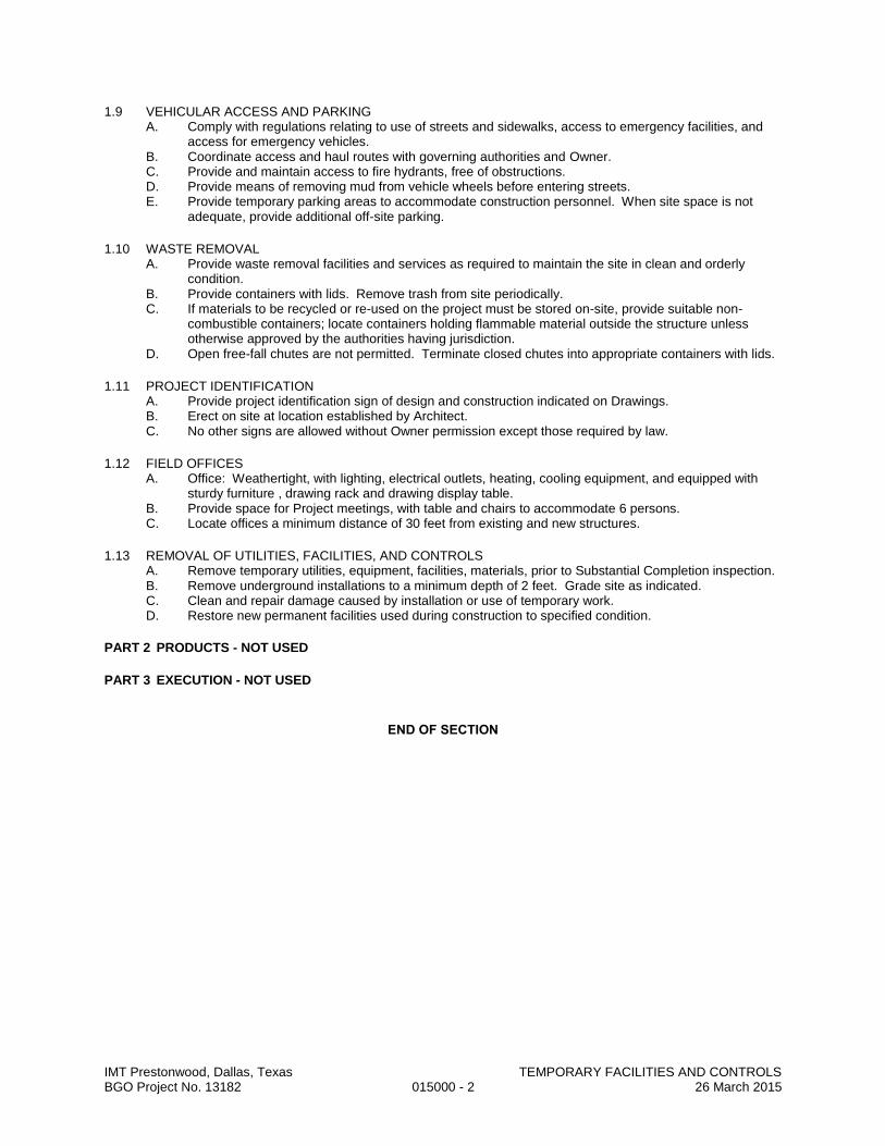
IMT Prestonwood, Dallas, Texas TEMPORARY FACILITIES AND CONTROLS BGO Project No. 13182 015000 - 2 26 March 2015
1.9 VEHICULAR ACCESS AND PARKING A. Comply with regulations relating to use of streets and sidewalks, access to emergency facilities, and
access for emergency vehicles. B. Coordinate access and haul routes with governing authorities and Owner. C. Provide and maintain access to fire hydrants, free of obstructions. D. Provide means of removing mud from vehicle wheels before entering streets. E. Provide temporary parking areas to accommodate construction personnel. When site space is not
adequate, provide additional off-site parking.
1.10 WASTE REMOVAL A. Provide waste removal facilities and services as required to maintain the site in clean and orderly
condition. B. Provide containers with lids. Remove trash from site periodically. C. If materials to be recycled or re-used on the project must be stored on-site, provide suitable non-
combustible containers; locate containers holding flammable material outside the structure unless otherwise approved by the authorities having jurisdiction.
D. Open free-fall chutes are not permitted. Terminate closed chutes into appropriate containers with lids.
1.11 PROJECT IDENTIFICATION A. Provide project identification sign of design and construction indicated on Drawings. B. Erect on site at location established by Architect. C. No other signs are allowed without Owner permission except those required by law.
1.12 FIELD OFFICES A. Office: Weathertight, with lighting, electrical outlets, heating, cooling equipment, and equipped with
sturdy furniture , drawing rack and drawing display table. B. Provide space for Project meetings, with table and chairs to accommodate 6 persons. C. Locate offices a minimum distance of 30 feet from existing and new structures.
1.13 REMOVAL OF UTILITIES, FACILITIES, AND CONTROLS A. Remove temporary utilities, equipment, facilities, materials, prior to Substantial Completion inspection. B. Remove underground installations to a minimum depth of 2 feet. Grade site as indicated. C. Clean and repair damage caused by installation or use of temporary work. D. Restore new permanent facilities used during construction to specified condition.
PART 2 PRODUCTS - NOT USED
PART 3 EXECUTION - NOT USED
END OF SECTION

IMT Prestonwood, Dallas, Texas MOLD PREVENTION MEASURES BGO Project No. 13182 015300 - 1 26 March 2015
SECTION 015300
MOLD PREVENTION MEASURES
PART 1 - GENERAL
1.1 SECTION INCLUDES A. Administrative and procedural requirements to help prevent mold contamination in construction.
1.2 SUBMITTALS A. Reports: Submit reports required in this Section, including but not limited to the following:
1. Sightings of existing mold. 2. Window and storefront testing. 3. Moisture contents of materials. 4. Exterior sealant cracks, damage, and deterioration.
1.3 QUALITY ASSURANCE A. Preconstruction Meeting: Review requirements of this Section at Preconstruction Meeting.
1.4 PRODUCT DELIVERY, STORAGE, AND HANDLING A. Deliver, store, and handle products using means and methods that will prevent damage, deterioration, and
loss, including theft. Comply with manufacturer's written instructions. B. Do not bring finish materials into building until building is in a conditioned state. Protect finish materials
stored within building. Stage materials off the floor and cover with waterproof covering. Examples of these materials include, but are not limited to, insulation, gypsum products, wall coverings, carpet, ceiling tile, wood products, etc.
C. Remove from Project site damaged materials or materials that have become wet. Do not install such materials.
1.5 PROJECT CONDITIONS A. Perform daily visual inspections of existing building for existing mold. Report sightings of mold to Owner’s
Representative. B. Remove water found within building during construction immediately.
1. Energize lift stations and sump pumps as early in Project as possible. Use temporary pumps if necessary to get water out of building and drain lines.
C. Ventilation: 1. Verify that existing HVAC system is providing positive pressure in building. 2. Provide adequate air circulation and ventilation during demolition phase(s). 3. Seal off return air ducts and diffusers to prevent construction dust and moisture from entering
occupied areas and HVAC system. 4. Provide temporary outside air ventilation as building becomes enclosed.
D. Maintain clean project site, free from hazards, garbage, and debris. E. Eating, drinking, and smoking are not permitted within building. F. Slope perimeter grades, both temporary and final grades, away from building structure. G. Verify that condensate pans drain properly beginning with initial installation. H. Flash roof penetrations immediately. Do not allow water to penetrate to floor below. I. Seal window openings prior to window installation with plastic to prevent moisture entry. J. Sprayed-on Fireproofing: Keep air moving throughout building when using sprayed-on fireproofing. K. Cover stored and installed ductwork and installed duct openings with plastic to prevent dust, debris, and
moisture from entering ductwork. Repair damaged plastic barrier. L. Do not operate air handling equipment below 60 degrees F supply air temperature until building is 100
percent enclosed. M. Monitor humidity and temperature for conformance to installation requirements defined by material and
equipment manufacturers. N. Check moisture content of gypsum board prior to applying finishes. Record findings.
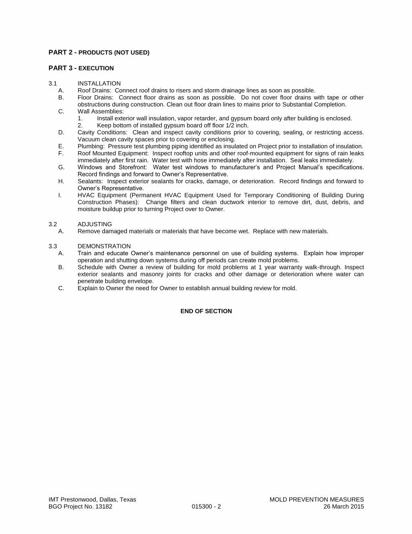
IMT Prestonwood, Dallas, Texas MOLD PREVENTION MEASURES BGO Project No. 13182 015300 - 2 26 March 2015
PART 2 - PRODUCTS (NOT USED)
PART 3 - EXECUTION
3.1 INSTALLATION A. Roof Drains: Connect roof drains to risers and storm drainage lines as soon as possible. B. Floor Drains: Connect floor drains as soon as possible. Do not cover floor drains with tape or other
obstructions during construction. Clean out floor drain lines to mains prior to Substantial Completion. C. Wall Assemblies:
1. Install exterior wall insulation, vapor retarder, and gypsum board only after building is enclosed. 2. Keep bottom of installed gypsum board off floor 1/2 inch.
D. Cavity Conditions: Clean and inspect cavity conditions prior to covering, sealing, or restricting access. Vacuum clean cavity spaces prior to covering or enclosing.
E. Plumbing: Pressure test plumbing piping identified as insulated on Project prior to installation of insulation. F. Roof Mounted Equipment: Inspect rooftop units and other roof-mounted equipment for signs of rain leaks
immediately after first rain. Water test with hose immediately after installation. Seal leaks immediately. G. Windows and Storefront: Water test windows to manufacturer’s and Project Manual’s specifications.
Record findings and forward to Owner’s Representative. H. Sealants: Inspect exterior sealants for cracks, damage, or deterioration. Record findings and forward to
Owner’s Representative. I. HVAC Equipment (Permanent HVAC Equipment Used for Temporary Conditioning of Building During
Construction Phases): Change filters and clean ductwork interior to remove dirt, dust, debris, and moisture buildup prior to turning Project over to Owner.
3.2 ADJUSTING A. Remove damaged materials or materials that have become wet. Replace with new materials.
3.3 DEMONSTRATION A. Train and educate Owner’s maintenance personnel on use of building systems. Explain how improper
operation and shutting down systems during off periods can create mold problems. B. Schedule with Owner a review of building for mold problems at 1 year warranty walk-through. Inspect
exterior sealants and masonry joints for cracks and other damage or deterioration where water can penetrate building envelope.
C. Explain to Owner the need for Owner to establish annual building review for mold.
END OF SECTION

IMT Prestonwood, Dallas, Texas TEMPORARY EROSION AND SEDIMENT CONTROL BGO Project No. 13182 015713 - 1 26 March 2015
SECTION 015713
TEMPORARY EROSION AND SEDIMENT CONTROL
PART 1 GENERAL
1.1 SECTION INCLUDES A. Prevention of erosion due to construction activities. B. Prevention of sedimentation of waterways, open drainage ways, and storm and sanitary sewers due to
construction activities. C. Restoration of areas eroded due to insufficient preventive measures. D. Compensation of Owner for fines levied by authorities having jurisdiction due to non-compliance by
Contractor.
1.2 PERFORMANCE REQUIREMENTS A. Comply with all requirements of U.S. Environmental Protection Agency for erosion and sedimentation
control, as specified for the National Pollutant Discharge Elimination System (NPDES), Phases I and II, under requirements for the 2012 Construction General Permit (CGP) , whether the project is required by law to comply or not.
B. Also comply with all more stringent requirements of local jurisdiction. C. Develop and follow an Erosion and Sedimentation Prevention Plan and submit periodic inspection
reports. D. Do not begin clearing, grading, or other work involving disturbance of ground surface cover until
applicable permits have been obtained; furnish all documentation required to obtain applicable permits. E. Timing: Put preventive measures in place as soon as possible after disturbance of surface cover and
before precipitation occurs. F. Storm Water Runoff: Control increased storm water runoff due to disturbance of surface cover due to
construction activities for this project. 1. Prevent runoff into storm and sanitary sewer systems, including open drainage channels, in
excess of actual capacity or amount allowed by authorities having jurisdiction, whichever is less.
2. Anticipate runoff volume due to the most extreme short term and 24-hour rainfall events that might occur in 25 years.
G. Erosion On Site: Minimize wind, water, and vehicular erosion of soil on project site due to construction activities for this project. 1. Control movement of sediment and soil from temporary stockpiles of soil. 2. Prevent development of ruts due to equipment and vehicular traffic. 3. If erosion occurs due to non-compliance with these requirements, restore eroded areas at no
cost to Owner. H. Erosion Off Site: Prevent erosion of soil and deposition of sediment on other properties caused by
water leaving the project site due to construction activities for this project. 1. Prevent windblown soil from leaving the project site. 2. Prevent tracking of mud onto public roads outside site. 3. Prevent mud and sediment from flowing onto sidewalks and pavements. 4. If erosion occurs due to non-compliance with these requirements, restore eroded areas at no
cost to Owner. I. Sedimentation of Waterways On Site: Prevent sedimentation of waterways on the project site,
including rivers, streams, lakes, ponds, open drainage ways, storm sewers, and sanitary sewers. 1. If sedimentation occurs, install or correct preventive measures immediately at no cost to Owner;
remove deposited sediments; comply with requirements of authorities having jurisdiction. 2. If sediment basins are used as temporary preventive measures, pump dry and remove
deposited sediment after each storm. J. Sedimentation of Waterways Off Site: Prevent sedimentation of waterways off the project site,
including rivers, streams, lakes, ponds, open drainage ways, storm sewers, and sanitary sewers. 1. If sedimentation occurs, install or correct preventive measures immediately at no cost to Owner;
remove deposited sediments; comply with requirements of authorities having jurisdiction. K. Open Water: Prevent standing water that could become stagnant. L. Maintenance: Maintain temporary preventive measures until permanent measures have been
established.
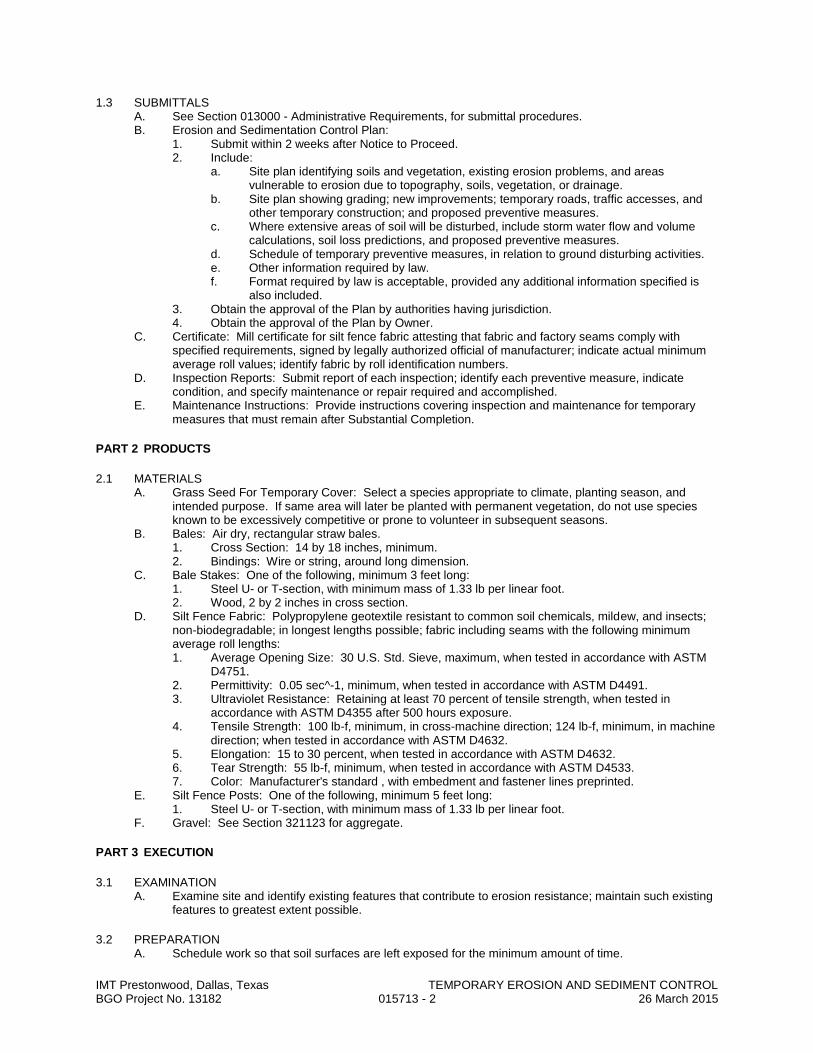
IMT Prestonwood, Dallas, Texas TEMPORARY EROSION AND SEDIMENT CONTROL BGO Project No. 13182 015713 - 2 26 March 2015
1.3 SUBMITTALS A. See Section 013000 - Administrative Requirements, for submittal procedures. B. Erosion and Sedimentation Control Plan:
1. Submit within 2 weeks after Notice to Proceed. 2. Include:
a. Site plan identifying soils and vegetation, existing erosion problems, and areas vulnerable to erosion due to topography, soils, vegetation, or drainage.
b. Site plan showing grading; new improvements; temporary roads, traffic accesses, and other temporary construction; and proposed preventive measures.
c. Where extensive areas of soil will be disturbed, include storm water flow and volume calculations, soil loss predictions, and proposed preventive measures.
d. Schedule of temporary preventive measures, in relation to ground disturbing activities. e. Other information required by law. f. Format required by law is acceptable, provided any additional information specified is
also included. 3. Obtain the approval of the Plan by authorities having jurisdiction. 4. Obtain the approval of the Plan by Owner.
C. Certificate: Mill certificate for silt fence fabric attesting that fabric and factory seams comply with specified requirements, signed by legally authorized official of manufacturer; indicate actual minimum average roll values; identify fabric by roll identification numbers.
D. Inspection Reports: Submit report of each inspection; identify each preventive measure, indicate condition, and specify maintenance or repair required and accomplished.
E. Maintenance Instructions: Provide instructions covering inspection and maintenance for temporary measures that must remain after Substantial Completion.
PART 2 PRODUCTS
2.1 MATERIALS A. Grass Seed For Temporary Cover: Select a species appropriate to climate, planting season, and
intended purpose. If same area will later be planted with permanent vegetation, do not use species known to be excessively competitive or prone to volunteer in subsequent seasons.
B. Bales: Air dry, rectangular straw bales. 1. Cross Section: 14 by 18 inches, minimum. 2. Bindings: Wire or string, around long dimension.
C. Bale Stakes: One of the following, minimum 3 feet long: 1. Steel U- or T-section, with minimum mass of 1.33 lb per linear foot. 2. Wood, 2 by 2 inches in cross section.
D. Silt Fence Fabric: Polypropylene geotextile resistant to common soil chemicals, mildew, and insects; non-biodegradable; in longest lengths possible; fabric including seams with the following minimum average roll lengths: 1. Average Opening Size: 30 U.S. Std. Sieve, maximum, when tested in accordance with ASTM
D4751. 2. Permittivity: 0.05 sec^-1, minimum, when tested in accordance with ASTM D4491. 3. Ultraviolet Resistance: Retaining at least 70 percent of tensile strength, when tested in
accordance with ASTM D4355 after 500 hours exposure. 4. Tensile Strength: 100 lb-f, minimum, in cross-machine direction; 124 lb-f, minimum, in machine
direction; when tested in accordance with ASTM D4632. 5. Elongation: 15 to 30 percent, when tested in accordance with ASTM D4632. 6. Tear Strength: 55 lb-f, minimum, when tested in accordance with ASTM D4533. 7. Color: Manufacturer's standard , with embedment and fastener lines preprinted.
E. Silt Fence Posts: One of the following, minimum 5 feet long: 1. Steel U- or T-section, with minimum mass of 1.33 lb per linear foot.
F. Gravel: See Section 321123 for aggregate.
PART 3 EXECUTION
3.1 EXAMINATION A. Examine site and identify existing features that contribute to erosion resistance; maintain such existing
features to greatest extent possible.
3.2 PREPARATION A. Schedule work so that soil surfaces are left exposed for the minimum amount of time.
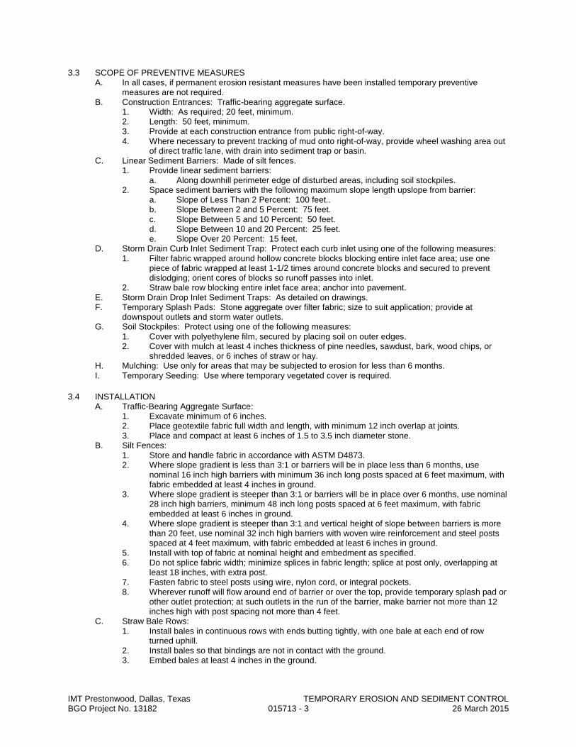
IMT Prestonwood, Dallas, Texas TEMPORARY EROSION AND SEDIMENT CONTROL BGO Project No. 13182 015713 - 3 26 March 2015
3.3 SCOPE OF PREVENTIVE MEASURES A. In all cases, if permanent erosion resistant measures have been installed temporary preventive
measures are not required. B. Construction Entrances: Traffic-bearing aggregate surface.
1. Width: As required; 20 feet, minimum. 2. Length: 50 feet, minimum. 3. Provide at each construction entrance from public right-of-way. 4. Where necessary to prevent tracking of mud onto right-of-way, provide wheel washing area out
of direct traffic lane, with drain into sediment trap or basin. C. Linear Sediment Barriers: Made of silt fences.
1. Provide linear sediment barriers: a. Along downhill perimeter edge of disturbed areas, including soil stockpiles.
2. Space sediment barriers with the following maximum slope length upslope from barrier: a. Slope of Less Than 2 Percent: 100 feet.. b. Slope Between 2 and 5 Percent: 75 feet. c. Slope Between 5 and 10 Percent: 50 feet. d. Slope Between 10 and 20 Percent: 25 feet. e. Slope Over 20 Percent: 15 feet.
D. Storm Drain Curb Inlet Sediment Trap: Protect each curb inlet using one of the following measures: 1. Filter fabric wrapped around hollow concrete blocks blocking entire inlet face area; use one
piece of fabric wrapped at least 1-1/2 times around concrete blocks and secured to prevent dislodging; orient cores of blocks so runoff passes into inlet.
2. Straw bale row blocking entire inlet face area; anchor into pavement. E. Storm Drain Drop Inlet Sediment Traps: As detailed on drawings. F. Temporary Splash Pads: Stone aggregate over filter fabric; size to suit application; provide at
downspout outlets and storm water outlets. G. Soil Stockpiles: Protect using one of the following measures:
1. Cover with polyethylene film, secured by placing soil on outer edges. 2. Cover with mulch at least 4 inches thickness of pine needles, sawdust, bark, wood chips, or
shredded leaves, or 6 inches of straw or hay. H. Mulching: Use only for areas that may be subjected to erosion for less than 6 months. I. Temporary Seeding: Use where temporary vegetated cover is required.
3.4 INSTALLATION A. Traffic-Bearing Aggregate Surface:
1. Excavate minimum of 6 inches. 2. Place geotextile fabric full width and length, with minimum 12 inch overlap at joints. 3. Place and compact at least 6 inches of 1.5 to 3.5 inch diameter stone.
B. Silt Fences: 1. Store and handle fabric in accordance with ASTM D4873. 2. Where slope gradient is less than 3:1 or barriers will be in place less than 6 months, use
nominal 16 inch high barriers with minimum 36 inch long posts spaced at 6 feet maximum, with fabric embedded at least 4 inches in ground.
3. Where slope gradient is steeper than 3:1 or barriers will be in place over 6 months, use nominal 28 inch high barriers, minimum 48 inch long posts spaced at 6 feet maximum, with fabric embedded at least 6 inches in ground.
4. Where slope gradient is steeper than 3:1 and vertical height of slope between barriers is more than 20 feet, use nominal 32 inch high barriers with woven wire reinforcement and steel posts spaced at 4 feet maximum, with fabric embedded at least 6 inches in ground.
5. Install with top of fabric at nominal height and embedment as specified. 6. Do not splice fabric width; minimize splices in fabric length; splice at post only, overlapping at
least 18 inches, with extra post. 7. Fasten fabric to steel posts using wire, nylon cord, or integral pockets. 8. Wherever runoff will flow around end of barrier or over the top, provide temporary splash pad or
other outlet protection; at such outlets in the run of the barrier, make barrier not more than 12 inches high with post spacing not more than 4 feet.
C. Straw Bale Rows: 1. Install bales in continuous rows with ends butting tightly, with one bale at each end of row
turned uphill. 2. Install bales so that bindings are not in contact with the ground. 3. Embed bales at least 4 inches in the ground.
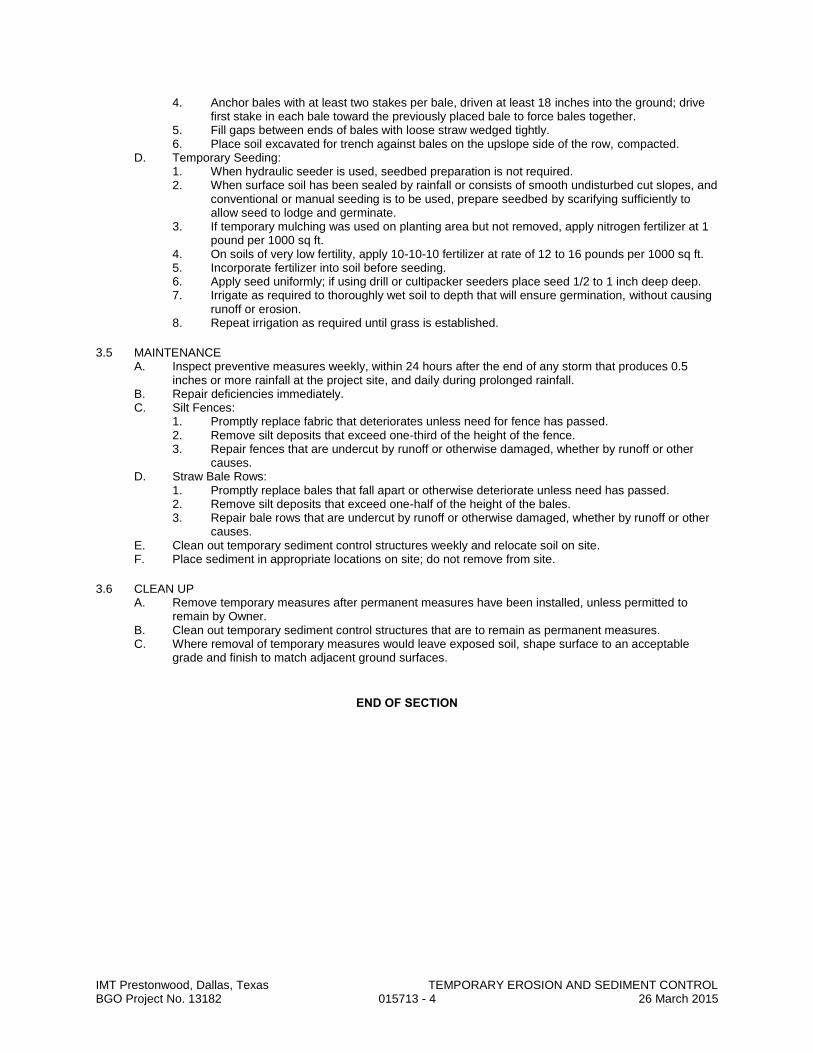
IMT Prestonwood, Dallas, Texas TEMPORARY EROSION AND SEDIMENT CONTROL BGO Project No. 13182 015713 - 4 26 March 2015
4. Anchor bales with at least two stakes per bale, driven at least 18 inches into the ground; drive first stake in each bale toward the previously placed bale to force bales together.
5. Fill gaps between ends of bales with loose straw wedged tightly. 6. Place soil excavated for trench against bales on the upslope side of the row, compacted.
D. Temporary Seeding: 1. When hydraulic seeder is used, seedbed preparation is not required. 2. When surface soil has been sealed by rainfall or consists of smooth undisturbed cut slopes, and
conventional or manual seeding is to be used, prepare seedbed by scarifying sufficiently to allow seed to lodge and germinate.
3. If temporary mulching was used on planting area but not removed, apply nitrogen fertilizer at 1 pound per 1000 sq ft.
4. On soils of very low fertility, apply 10-10-10 fertilizer at rate of 12 to 16 pounds per 1000 sq ft. 5. Incorporate fertilizer into soil before seeding. 6. Apply seed uniformly; if using drill or cultipacker seeders place seed 1/2 to 1 inch deep deep. 7. Irrigate as required to thoroughly wet soil to depth that will ensure germination, without causing
runoff or erosion. 8. Repeat irrigation as required until grass is established.
3.5 MAINTENANCE A. Inspect preventive measures weekly, within 24 hours after the end of any storm that produces 0.5
inches or more rainfall at the project site, and daily during prolonged rainfall. B. Repair deficiencies immediately. C. Silt Fences:
1. Promptly replace fabric that deteriorates unless need for fence has passed. 2. Remove silt deposits that exceed one-third of the height of the fence. 3. Repair fences that are undercut by runoff or otherwise damaged, whether by runoff or other
causes. D. Straw Bale Rows:
1. Promptly replace bales that fall apart or otherwise deteriorate unless need has passed. 2. Remove silt deposits that exceed one-half of the height of the bales. 3. Repair bale rows that are undercut by runoff or otherwise damaged, whether by runoff or other
causes. E. Clean out temporary sediment control structures weekly and relocate soil on site. F. Place sediment in appropriate locations on site; do not remove from site.
3.6 CLEAN UP A. Remove temporary measures after permanent measures have been installed, unless permitted to
remain by Owner. B. Clean out temporary sediment control structures that are to remain as permanent measures. C. Where removal of temporary measures would leave exposed soil, shape surface to an acceptable
grade and finish to match adjacent ground surfaces.
END OF SECTION

IMT Prestonwood, Dallas, Texas PRODUCT REQUIREMENTS BGO Project No. 13182 016000 - 1 26 March 2015
SECTION 016000
PRODUCT REQUIREMENTS
PART 1 GENERAL
1.1 SECTION INCLUDES A. General product requirements. B. Transportation, handling, storage and protection. C. Product option requirements. D. Substitution limitations and procedures. E. Maintenance materials, including extra materials, spare parts, tools, and software.
1.2 SUBMITTALS A. Proposed Products List: Submit list of major products proposed for use, with name of manufacturer,
trade name, and model number of each product. 1. Submit within 15 days after date of Agreement. 2. For products specified only by reference standards, list applicable reference standards.
B. Product Data Submittals: Submit manufacturer's standard published data. Mark each copy to identify applicable products, models, options, and other data. Supplement manufacturers' standard data to provide information specific to this Project.
C. Shop Drawing Submittals: Prepared specifically for this Project; indicate utility and electrical characteristics, utility connection requirements, and location of utility outlets for service for functional equipment and appliances.
D. Sample Submittals: Illustrate functional and aesthetic characteristics of the product, with integral parts and attachment devices. Coordinate sample submittals for interfacing work. 1. For selection from standard finishes, submit samples of the full range of the manufacturer's
standard colors, textures, and patterns.
PART 2 PRODUCTS
2.1 NEW PRODUCTS A. Provide new products unless specifically required or permitted by the Contract Documents. B. Do not use products having any of the following characteristics:
1. Made outside the United States, its territories, Canada, or Mexico. 2. Made using or containing CFC's or HCFC's. 3. Made of wood from newly cut old growth timber.
C. Where all other criteria are met, Contractor shall give preference to products that: 1. Are extracted, harvested, and/or manufactured closer to the location of the project. 2. Have longer documented life span under normal use. 3. Result in less construction waste. 4. Are made of vegetable materials that are rapidly renewable.
D. Provide interchangeable components of the same manufacture for components being replaced. E. Wiring Terminations: Provide terminal lugs to match branch circuit conductor quantities, sizes, and
materials indicated. Size terminal lugs to NFPA 70, include lugs for terminal box. F. Cord and Plug: Provide minimum 6 foot cord and plug including grounding connector for connection to
electric wiring system. Cord of longer length is specified in individual specification sections.
2.2 PRODUCT OPTIONS A. Products Specified by Reference Standards or by Description Only: Use any product meeting those
standards or description. B. Products Specified by Naming One or More Manufacturers: Use a product of one of the manufacturers
named and meeting specifications, no options or substitutions allowed. C. Products Specified by Naming One or More Manufacturers with a Provision for Substitutions: Submit a
request for substitution for any manufacturer not named.
2.3 MAINTENANCE MATERIALS A. Furnish extra materials, spare parts, tools, and software of types and in quantities specified in
individual specification sections. B. Deliver to Project site; obtain receipt prior to final payment.
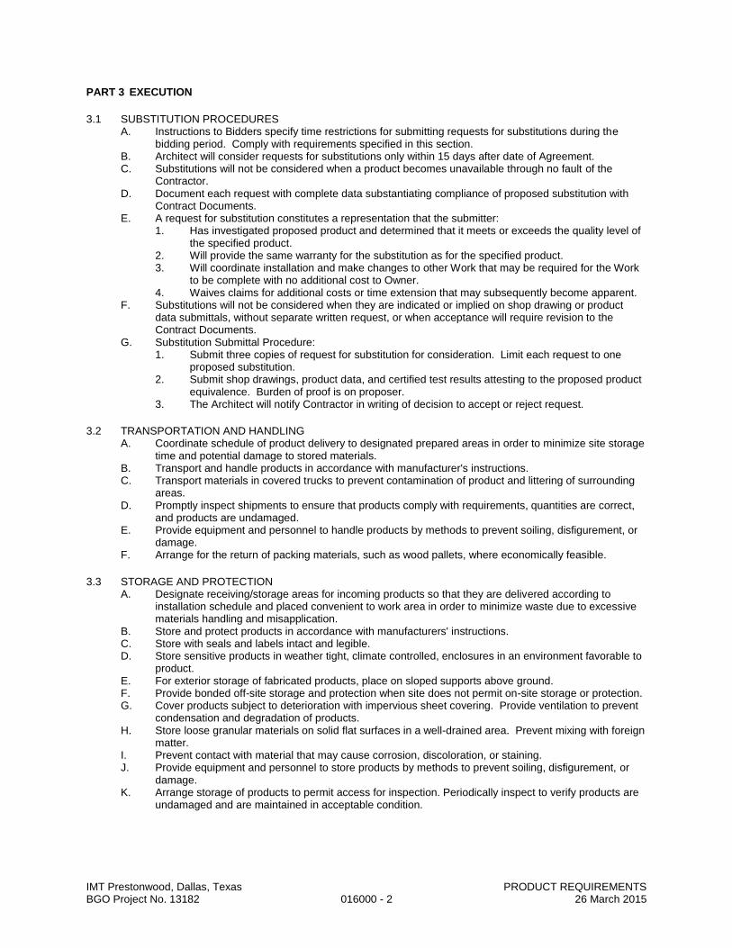
IMT Prestonwood, Dallas, Texas PRODUCT REQUIREMENTS BGO Project No. 13182 016000 - 2 26 March 2015
PART 3 EXECUTION
3.1 SUBSTITUTION PROCEDURES A. Instructions to Bidders specify time restrictions for submitting requests for substitutions during the
bidding period. Comply with requirements specified in this section. B. Architect will consider requests for substitutions only within 15 days after date of Agreement. C. Substitutions will not be considered when a product becomes unavailable through no fault of the
Contractor. D. Document each request with complete data substantiating compliance of proposed substitution with
Contract Documents. E. A request for substitution constitutes a representation that the submitter:
1. Has investigated proposed product and determined that it meets or exceeds the quality level of the specified product.
2. Will provide the same warranty for the substitution as for the specified product. 3. Will coordinate installation and make changes to other Work that may be required for the Work
to be complete with no additional cost to Owner. 4. Waives claims for additional costs or time extension that may subsequently become apparent.
F. Substitutions will not be considered when they are indicated or implied on shop drawing or product data submittals, without separate written request, or when acceptance will require revision to the Contract Documents.
G. Substitution Submittal Procedure: 1. Submit three copies of request for substitution for consideration. Limit each request to one
proposed substitution. 2. Submit shop drawings, product data, and certified test results attesting to the proposed product
equivalence. Burden of proof is on proposer. 3. The Architect will notify Contractor in writing of decision to accept or reject request.
3.2 TRANSPORTATION AND HANDLING A. Coordinate schedule of product delivery to designated prepared areas in order to minimize site storage
time and potential damage to stored materials. B. Transport and handle products in accordance with manufacturer's instructions. C. Transport materials in covered trucks to prevent contamination of product and littering of surrounding
areas. D. Promptly inspect shipments to ensure that products comply with requirements, quantities are correct,
and products are undamaged. E. Provide equipment and personnel to handle products by methods to prevent soiling, disfigurement, or
damage. F. Arrange for the return of packing materials, such as wood pallets, where economically feasible.
3.3 STORAGE AND PROTECTION A. Designate receiving/storage areas for incoming products so that they are delivered according to
installation schedule and placed convenient to work area in order to minimize waste due to excessive materials handling and misapplication.
B. Store and protect products in accordance with manufacturers' instructions. C. Store with seals and labels intact and legible. D. Store sensitive products in weather tight, climate controlled, enclosures in an environment favorable to
product. E. For exterior storage of fabricated products, place on sloped supports above ground. F. Provide bonded off-site storage and protection when site does not permit on-site storage or protection. G. Cover products subject to deterioration with impervious sheet covering. Provide ventilation to prevent
condensation and degradation of products. H. Store loose granular materials on solid flat surfaces in a well-drained area. Prevent mixing with foreign
matter. I. Prevent contact with material that may cause corrosion, discoloration, or staining. J. Provide equipment and personnel to store products by methods to prevent soiling, disfigurement, or
damage. K. Arrange storage of products to permit access for inspection. Periodically inspect to verify products are
undamaged and are maintained in acceptable condition.
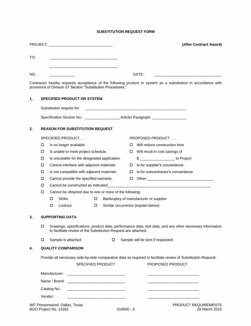
IMT Prestonwood, Dallas, Texas PRODUCT REQUIREMENTS BGO Project No. 13182 016000 - 3 26 March 2015
SUBSTITUTION REQUEST FORM
PROJECT: _______________________________ (After Contract Award)
TO: _________________________________ _________________________________ NO. ____________ DATE: _________________________________ Contractor hereby requests acceptance of the following product or system as a substitution in accordance with provisions of Division 01 Section “Substitution Procedures:”
1. SPECIFIED PRODUCT OR SYSTEM
Substitution request for: _________________________________________________
Specification Section No.: _________________ Article/ Paragraph: _________________
2. REASON FOR SUBSTITUTION REQUEST
SPECIFIED PRODUCT . . . PROPOSED PRODUCT . . .
Is no longer available. Will reduce construction time
Is unable to meet project schedule. Will result in cost savings of
Is unsuitable for the designated application. $ _________________ to Project
Cannot interface with adjacent materials. Is for supplier’s convenience
Is not compatible with adjacent materials. Is for subcontractor’s convenience
Cannot provide the specified warranty. Other:________________________________
Cannot be constructed as indicated__________________________________________________
Cannot be obtained due to one or more of the following:
Strike Bankruptcy of manufacturer or supplier
Lockout Similar occurrence (explain below)
3. SUPPORTING DATA
Drawings, specifications, product data, performance data, test data, and any other necessary information to facilitate review of the Substitution Request are attached.
Sample is attached. Sample will be sent if requested. 4. QUALITY COMPARISON
Provide all necessary side-by-side comparative data as required to facilitate review of Substitution Request:
SPECIFIED PRODUCT PROPOSED PRODUCT
Manufacturer: ____________________________ _________________________
Name / Brand: ____________________________ _________________________
Catalog No.: ____________________________ _________________________
Vendor: ____________________________ _________________________

IMT Prestonwood, Dallas, Texas PRODUCT REQUIREMENTS BGO Project No. 13182 016000 - 4 26 March 2015
Variations: _____________________________________________________
(Add Additional Sheets If Necessary)
Local Distributor or Supplier: ___________________________________________
Maintenance Service Available: Yes No
Spare Parts Source: __________________________________________________
Warranty: Yes No _____ Years
5. PREVIOUS INSTALLATIONS
Identification of at least three similar projects on which proposed substitution was used:
PROJECT #1:
Project: _______________________________________________________
Address: _______________________________________________________
_______________________________________________________
Architect: _______________________________________________________
Owner: _______________________________________________________
Contractor: _______________________________________________________
Date Installed: _______________________________________________________
PROJECT #2:
Project: _______________________________________________________
Address: _______________________________________________________
_______________________________________________________
Architect: _______________________________________________________
Owner: _______________________________________________________
Contractor: _______________________________________________________
Date Installed: _______________________________________________________
PROJECT #3:
Project: _______________________________________________________
Address: _______________________________________________________
_______________________________________________________
Architect: _______________________________________________________
Owner: _______________________________________________________
Contractor: _______________________________________________________

IMT Prestonwood, Dallas, Texas PRODUCT REQUIREMENTS BGO Project No. 13182 016000 - 5 26 March 2015
Date Installed: _______________________________________________________
6. EFFECT OF SUBSTITUTION
Proposed substitution affects other work or trades: No Yes (if Yes, explain)
_______________________________________________________________________ _______________________________________________________________________
Proposed substitution requires dimensional revisions or redesign of architectural, structural, M-E-P, life safety,
or other work:
No Yes (if Yes, attach data explaining revisions)
7. STATEMENT OF CONFORMANCE OF REQUEST TO CONTRACT REQUIREMENTS
Contractor and Subcontractor have investigated the proposed substitution and hereby represent that:
A. They have personally investigated the proposed substitution and believe that it is equal to or superior in all respects to specified product, except as stated above;
B. The proposed substitution is in compliance with applicable codes and ordinances;
C. The proposed substitution will provide same warranty as specified for specified product;
D. They will coordinate the incorporation of the proposed substitution into the Work, and will include modifications to the Work as required to fully integrate the substitution;
E. They have included complete cost data and implications of the substitution (attached);
F. They will pay any redesign fees incurred by the Architect or any of the Architect’s consultants, and any special inspection costs incurred by the Owner, caused by the use of this product;
G. They waive all future claims for added cost or time to the Contract related to the substitution, or that become known after substitution is accepted.
H. The Architect’s approval, if granted, will be based upon reliance upon data submitted and the opinion, knowledge, information, and belief of the Architect at the time decision is rendered and Addendum is issued; and that Architect’s approval therefore is interim in nature and subject to reevaluation and reconsideration as additional data, materials, workmanship, and coordination with other work are observed and reviewed.
Contractor:______________________________________________________________ (Name of Contractor)
Date: ___________________ By: _______________________________________ Subcontractor:__________________________________________________________
(Name of Subcontractor)
Date: ___________________ By: _______________________________________ Note: Unresponsive or incomplete requests will be rejected and returned without review.
8. ARCHITECT'S REVIEW AND ACTION
Substitution is accepted.
Substitution is accepted, with the following comments:______________________
___________________________________________________________________

IMT Prestonwood, Dallas, Texas PRODUCT REQUIREMENTS BGO Project No. 13182 016000 - 6 26 March 2015
___________________________________________________________________
Resubmit Substitution Request:
Provide more information in the following areas: ______________________
_______________________________________________________________
_______________________________________________________________
Provide proposal indicating amount of savings / credit to Owner
Bidding Contractor shall sign Bidder's Statement of Conformance
Bidding Subcontractor shall sign Bidder's Statement of Conformance
Substitution is not accepted:
Substitution Request received too late.
Substitution Request received directly from subcontractor or supplier.
Substitution Request not submitted in accordance with requirements.
Substitution Request Form is not properly executed.
Substitution Request does not indicate what item is being proposed.
Insufficient information submitted to facilitate proper evaluation.
Proposed product does not appear to comply with specified requirements.
Proposed product will require substantial revisions to Contract Documents. By: ___________________________________________ Date:________________________ Architect has relied upon the information provided by the Contractor, and makes no claim as to the accuracy, completeness, or validity of such information. If an accepted substitution is later found to be not in compliance with the Contract Documents, Contractor shall provide the specified product. 9. OWNER’S REVIEW AND ACTION
Substitution is accepted; Architect to prepare Change Order.
Substitution is not accepted.
Owner will pay Architect directly for redesign fees.
Include Architect’s Additional Service fee for implementing the substitution in the Change Order.
By: ____________________________________________ (Owner/Owner’s Representative)
Date:_____________________________________________
END OF FORM
END OF SECTION

IMT Prestonwood, Dallas, Texas EXECUTION AND CLOSEOUT REQUIREMENTS BGO Project No. 13182 017000 - 1 26 March 2015
SECTION 017000
EXECUTION AND CLOSEOUT REQUIREMENTS
PART 1 GENERAL
1.1 SECTION INCLUDES A. Examination, preparation, and general installation procedures. B. Pre-installation meetings. C. Cutting and patching. D. Surveying for laying out the work. E. Cleaning and protection. F. Starting of systems and equipment. G. Demonstration and instruction of Owner personnel. H. Closeout procedures, except payment procedures. I. General requirements for maintenance service.
1.2 SUBMITTALS A. See Section 013000 - Administrative Requirements, for submittal procedures. B. Survey work: Submit name, address, and telephone number of Surveyor before starting survey work.
1. On request, submit documentation verifying accuracy of survey work. 2. Submit a copy of site drawing signed by the Land Surveyor, that the elevations and locations of
the work are in conformance with Contract Documents. 3. Submit surveys and survey logs for the project record.
C. Cutting and Patching: Submit written request in advance of cutting or alteration that affects: 1. Structural integrity of any element of Project. 2. Integrity of weather exposed or moisture resistant element. 3. Efficiency, maintenance, or safety of any operational element. 4. Visual qualities of sight exposed elements. 5. Work of Owner or separate Contractor. 6. Include in request:
a. Identification of Project. b. Location and description of affected work. c. Necessity for cutting or alteration. d. Description of proposed work and products to be used. e. Effect on work of Owner or separate Contractor. f. Written permission of affected separate Contractor. g. Date and time work will be executed.
D. Project Record Documents: Accurately record actual locations of capped and active utilities.
1.3 QUALIFICATIONS A. For survey work, employ a land surveyor registered in the State in which the Project is located and
acceptable to Architect. Submit evidence of Surveyor's Errors and Omissions insurance coverage in the form of an Insurance Certificate.
B. For field engineering, employ a professional engineer of the discipline required for specific service on Project, licensed in the State in which the Project is located.
C. For design of temporary shoring and bracing, employ a Professional Engineer experienced in design of this type of work and licensed in the State in which the Project is located.
1.4 PROJECT CONDITIONS A. Use of explosives is not permitted. B. Grade site to drain. Maintain excavations free of water. Provide, operate, and maintain pumping
equipment. C. Protect site from puddling or running water. Provide water barriers as required to protect site from soil
erosion. D. Ventilate enclosed areas to assist cure of materials, to dissipate humidity, and to prevent accumulation
of dust, fumes, vapors, or gases. E. Dust Control: Execute work by methods to minimize raising dust from construction operations.
Provide positive means to prevent air-borne dust from dispersing into atmosphere and over adjacent property.
F. Erosion and Sediment Control: Plan and execute work by methods to control surface drainage from cuts and fills, from borrow and waste disposal areas. Prevent erosion and sedimentation.

IMT Prestonwood, Dallas, Texas EXECUTION AND CLOSEOUT REQUIREMENTS BGO Project No. 13182 017000 - 2 26 March 2015
1. Minimize amount of bare soil exposed at one time. 2. Provide temporary measures such as berms, dikes, and drains, to prevent water flow. 3. Construct fill and waste areas by selective placement to avoid erosive surface silts or clays. 4. Periodically inspect earthwork to detect evidence of erosion and sedimentation; promptly apply
corrective measures. G. Noise Control: Provide methods, means, and facilities to minimize noise produced by construction
operations. H. Pest and Rodent Control: Provide methods, means, and facilities to prevent pests and insects from
damaging the work. I. Pollution Control: Provide methods, means, and facilities to prevent contamination of soil, water, and
atmosphere from discharge of noxious, toxic substances, and pollutants produced by construction operations. Comply with federal, state, and local regulations.
1.5 COORDINATION A. Coordinate scheduling, submittals, and work of the various sections of the Project Manual to ensure
efficient and orderly sequence of installation of interdependent construction elements , with provisions for accommodating items installed later.
B. Notify affected utility companies and comply with their requirements. C. Verify that utility requirements and characteristics of new operating equipment are compatible with
building utilities. Coordinate work of various sections having interdependent responsibilities for installing, connecting to, and placing in service, such equipment.
D. Coordinate space requirements, supports, and installation of mechanical and electrical work that are indicated diagrammatically on Drawings. Follow routing shown for pipes, ducts, and conduit, as closely as practicable; place runs parallel with lines of building. Utilize spaces efficiently to maximize accessibility for other installations, for maintenance, and for repairs.
E. In finished areas except as otherwise indicated, conceal pipes, ducts, and wiring within the construction. Coordinate locations of fixtures and outlets with finish elements.
F. Coordinate completion and clean-up of work of separate sections. G. After Owner occupancy of premises, coordinate access to site for correction of defective work and
work not in accordance with Contract Documents, to minimize disruption of Owner's activities.
PART 2 PRODUCTS
2.1 PATCHING MATERIALS A. New Materials: As specified in product sections; match existing products and work for patching and
extending work. B. Type and Quality of Existing Products: Determine by inspecting and testing products where
necessary, referring to existing work as a standard. C. Product Substitution: For any proposed change in materials, submit request for substitution described
in Section 016000.
PART 3 EXECUTION
3.1 EXAMINATION A. Verify that existing site conditions and substrate surfaces are acceptable for subsequent work. Start of
work means acceptance of existing conditions. B. Verify that existing substrate is capable of structural support or attachment of new work being applied
or attached. C. Examine and verify specific conditions described in individual specification sections. D. Take field measurements before confirming product orders or beginning fabrication, to minimize waste
due to over-ordering or misfabrication. E. Verify that utility services are available, of the correct characteristics, and in the correct locations. F. Prior to Cutting: Examine existing conditions prior to commencing work, including elements subject to
damage or movement during cutting and patching. After uncovering existing work, assess conditions affecting performance of work. Beginning of cutting or patching means acceptance of existing conditions.
3.2 PREPARATION A. Clean substrate surfaces prior to applying next material or substance. B. Seal cracks or openings of substrate prior to applying next material or substance. C. Apply manufacturer required or recommended substrate primer, sealer, or conditioner prior to applying
any new material or substance in contact or bond.
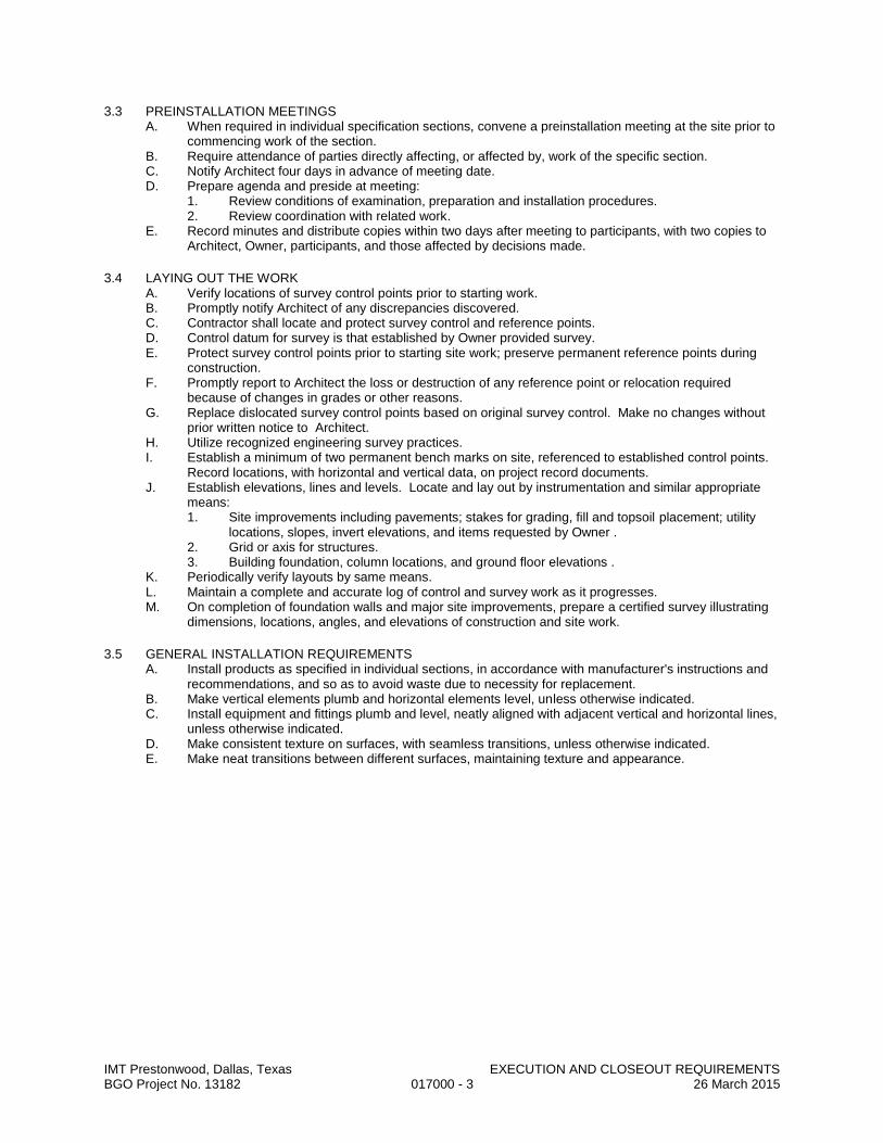
IMT Prestonwood, Dallas, Texas EXECUTION AND CLOSEOUT REQUIREMENTS BGO Project No. 13182 017000 - 3 26 March 2015
3.3 PREINSTALLATION MEETINGS A. When required in individual specification sections, convene a preinstallation meeting at the site prior to
commencing work of the section. B. Require attendance of parties directly affecting, or affected by, work of the specific section. C. Notify Architect four days in advance of meeting date. D. Prepare agenda and preside at meeting:
1. Review conditions of examination, preparation and installation procedures. 2. Review coordination with related work.
E. Record minutes and distribute copies within two days after meeting to participants, with two copies to Architect, Owner, participants, and those affected by decisions made.
3.4 LAYING OUT THE WORK A. Verify locations of survey control points prior to starting work. B. Promptly notify Architect of any discrepancies discovered. C. Contractor shall locate and protect survey control and reference points. D. Control datum for survey is that established by Owner provided survey. E. Protect survey control points prior to starting site work; preserve permanent reference points during
construction. F. Promptly report to Architect the loss or destruction of any reference point or relocation required
because of changes in grades or other reasons. G. Replace dislocated survey control points based on original survey control. Make no changes without
prior written notice to Architect. H. Utilize recognized engineering survey practices. I. Establish a minimum of two permanent bench marks on site, referenced to established control points.
Record locations, with horizontal and vertical data, on project record documents. J. Establish elevations, lines and levels. Locate and lay out by instrumentation and similar appropriate
means: 1. Site improvements including pavements; stakes for grading, fill and topsoil placement; utility
locations, slopes, invert elevations, and items requested by Owner . 2. Grid or axis for structures. 3. Building foundation, column locations, and ground floor elevations .
K. Periodically verify layouts by same means. L. Maintain a complete and accurate log of control and survey work as it progresses. M. On completion of foundation walls and major site improvements, prepare a certified survey illustrating
dimensions, locations, angles, and elevations of construction and site work.
3.5 GENERAL INSTALLATION REQUIREMENTS A. Install products as specified in individual sections, in accordance with manufacturer's instructions and
recommendations, and so as to avoid waste due to necessity for replacement. B. Make vertical elements plumb and horizontal elements level, unless otherwise indicated. C. Install equipment and fittings plumb and level, neatly aligned with adjacent vertical and horizontal lines,
unless otherwise indicated. D. Make consistent texture on surfaces, with seamless transitions, unless otherwise indicated. E. Make neat transitions between different surfaces, maintaining texture and appearance.

IMT Prestonwood, Dallas, Texas EXECUTION AND CLOSEOUT REQUIREMENTS BGO Project No. 13182 017000 - 4 26 March 2015
3.6 CUTTING AND PATCHING A. Whenever possible, execute the work by methods that avoid cutting or patching. B. Perform whatever cutting and patching is necessary to:
1. Complete the work. 2. Fit products together to integrate with other work. 3. Provide openings for penetration of mechanical, electrical, and other services. 4. Match work that has been cut to adjacent work. 5. Repair areas adjacent to cuts to required condition. 6. Repair new work damaged by subsequent work. 7. Remove samples of installed work for testing when requested. 8. Remove and replace defective and non-conforming work.
C. Execute work by methods that avoid damage to other work and that will provide appropriate surfaces to receive patching and finishing. In existing work, minimize damage and restore to original condition.
D. Employ original installer to perform cutting for weather exposed and moisture resistant elements, and sight exposed surfaces.
E. Cut rigid materials using masonry saw or core drill. Pneumatic tools not allowed without prior approval. F. Restore work with new products in accordance with requirements of Contract Documents. G. Fit work air tight to pipes, sleeves, ducts, conduit, and other penetrations through surfaces. H. At penetrations of fire rated walls, partitions, ceiling, or floor construction, completely seal voids with
fire rated material in accordance with Section 078400, to full thickness of the penetrated element. I. Patching:
1. Finish patched surfaces to match finish that existed prior to patching. On continuous surfaces, refinish to nearest intersection or natural break. For an assembly, refinish entire unit.
2. Match color, texture, and appearance. 3. Repair patched surfaces that are damaged, lifted, discolored, or showing other imperfections
due to patching work. If defects are due to condition of substrate, repair substrate prior to repairing finish.
3.7 PROGRESS CLEANING A. Maintain areas free of waste materials, debris, and rubbish. Maintain site in a clean and orderly
condition. B. Remove debris and rubbish from pipe chases, plenums, attics, crawl spaces, and other closed or
remote spaces, prior to enclosing the space. C. Broom and vacuum clean interior areas prior to start of surface finishing, and continue cleaning to
eliminate dust. D. Collect and remove waste materials, debris, and trash/rubbish from site periodically and dispose off-
site; do not burn or bury.
3.8 PROTECTION OF INSTALLED WORK A. Protect installed work from damage by construction operations. B. Provide special protection where specified in individual specification sections. C. Provide temporary and removable protection for installed products. Control activity in immediate work
area to prevent damage. D. Provide protective coverings at walls, projections, jambs, sills, and soffits of openings. E. Protect finished floors, stairs, and other surfaces from traffic, dirt, wear, damage, or movement of
heavy objects, by protecting with durable sheet materials. F. Prohibit traffic or storage upon waterproofed or roofed surfaces. If traffic or activity is necessary, obtain
recommendations for protection from waterproofing or roofing material manufacturer. G. Remove protective coverings when no longer needed; reuse or recycle plastic coverings if possible.

IMT Prestonwood, Dallas, Texas EXECUTION AND CLOSEOUT REQUIREMENTS BGO Project No. 13182 017000 - 5 26 March 2015
3.9 SYSTEM STARTUP A. Coordinate schedule for start-up of various equipment and systems. B. Verify that each piece of equipment or system has been checked for proper lubrication, drive rotation,
belt tension, control sequence, and for conditions that may cause damage. C. Verify tests, meter readings, and specified electrical characteristics agree with those required by the
equipment or system manufacturer. D. Verify that wiring and support components for equipment are complete and tested. E. Execute start-up under supervision of applicable Contractor personnel and manufacturer's
representative in accordance with manufacturers' instructions. F. When specified in individual specification Sections, require manufacturer to provide authorized
representative to be present at site to inspect, check, and approve equipment or system installation prior to start-up, and to supervise placing equipment or system in operation.
G. Submit a written report that equipment or system has been properly installed and is functioning correctly.
3.10 DEMONSTRATION AND INSTRUCTION A. See Section 017900 - Demonstration and Training.
3.11 ADJUSTING A. Adjust operating products and equipment to ensure smooth and unhindered operation.
3.12 FINAL CLEANING A. Execute final cleaning prior to final project assessment.
1. Clean areas to be occupied by Owner prior to final completion before Owner occupancy. B. Use cleaning materials that are nonhazardous. C. Clean interior and exterior glass, surfaces exposed to view; remove temporary labels, stains and
foreign substances, polish transparent and glossy surfaces, vacuum carpeted and soft surfaces. D. Remove all labels that are not permanent. Do not paint or otherwise cover fire test labels or
nameplates on mechanical and electrical equipment. E. Clean equipment and fixtures to a sanitary condition with cleaning materials appropriate to the surface
and material being cleaned. F. Clean filters of operating equipment. G. Clean debris from roofs, gutters, downspouts, and drainage systems. H. Clean site; sweep paved areas, rake clean landscaped surfaces. I. Remove waste, surplus materials, trash/rubbish, and construction facilities from the site; dispose of in
legal manner; do not burn or bury.
3.13 CLOSEOUT PROCEDURES A. Make submittals that are required by governing or other authorities.
1. Provide copies to Architect and Owner. B. Accompany Project Coordinator on preliminary inspection to determine items to be listed for
completion or correction in Contractor's Notice of Substantial Completion. C. Notify Architect when work is considered ready for Substantial Completion. D. Submit written certification that Contract Documents have been reviewed, work has been inspected,
and that work is complete in accordance with Contract Documents and ready for Architect's review. E. Correct items of work listed in executed Certificates of Substantial Completion and comply with
requirements for access to Owner-occupied areas. F. Notify Architect when work is considered finally complete. G. Complete items of work determined by Architect's final inspection.
3.14 MAINTENANCE A. Provide service and maintenance of components indicated in specification sections. B. Maintenance Period: As indicated in specification sections or, if not indicated, not less than one year
from the Date of Substantial Completion or the length of the specified warranty, whichever is longer. C. Examine system components at a frequency consistent with reliable operation. Clean, adjust, and
lubricate as required. D. Include systematic examination, adjustment, and lubrication of components. Repair or replace parts
whenever required. Use parts produced by the manufacturer of the original component. E. Maintenance service shall not be assigned or transferred to any agent or subcontractor without prior
written consent of the Owner. END OF SECTION
IMT Prestonwood, Dallas, Texas CONSTRUCTION WASTE MANAGEMENT AND DISPOSAL BGO Project No. 13182 017419 - 1 26 March 2015
SECTION 017419
CONSTRUCTION WASTE MANAGEMENT AND DISPOSAL
PART 1 - GENERAL
1.1 RELATED DOCUMENTS A. Drawings and general provisions of the Contract, including General and Supplementary Conditions and
other Division 01 Specification Sections, apply to this Section.
1.2 SUMMARY A. Section includes administrative and procedural requirements for the following:
1. Salvaging non-hazardous construction waste. 2. Recycling non-hazardous construction waste. 3. Disposing of non-hazardous construction waste.
1.3 DEFINITIONS A. Construction Waste: Building and site improvement materials and other solid waste resulting from
construction, remodeling, renovation, or repair operations. Construction waste includes packaging. Soil and land-clearing debris are excluded from construction waste calculations.
B. Demolition Waste: Building and site improvement materials resulting from demolition or selective demolition operations.
C. Disposal: Removal off-site of construction waste and subsequent sale, recycling, reuse, or deposit in landfill or incinerator acceptable to authorities having jurisdiction.
D. Recycle: Recovery of demolition or construction waste for subsequent processing in preparation for reuse. E. Salvage: Recovery of demolition or construction waste and subsequent sale or reuse in another facility. F. Salvage and Reuse: Recovery of demolition or construction waste and subsequent incorporation into the
Work.
1.4 PERFORMANCE REQUIREMENTS A. General: Achieve end-of-Project rates for salvage/recycling of 75 percent by weight of total non-
hazardous solid waste generated by the Work in accordance with LEED V3, Credit MRc2. Practice efficient waste management in the use of materials in the course of the Work. Use all reasonable means to divert construction and demolition waste from landfills and incinerators. Facilitate recycling and salvage of materials, including the following: 1. Demolition Waste:
a. Concrete. b. Concrete reinforcing steel. c. Brick. d. Concrete masonry units. e. Doors and frames. f. Door hardware. g. Metal studs. h. Gypsum board. i. Acoustical tile and panels. j. Carpet. k. Carpet pad. l. Plumbing fixtures. m. Piping. n. Mechanical equipment. o. Refrigerants. p. Electrical conduit. q. Copper wiring. r. Lighting fixtures. s. Switchgear and panelboards. t. Transformers.
2. Construction Waste: a. Site-clearing waste. b. Masonry and CMU. c. Lumber.

IMT Prestonwood, Dallas, Texas CONSTRUCTION WASTE MANAGEMENT AND DISPOSAL BGO Project No. 13182 017419 - 2 26 March 2015
d. Wood sheet materials. e. Wood trim. f. Metals. g. Carpet and pad. h. Gypsum board. i. Piping. j. Electrical conduit. k. Packaging: Regardless of salvage/recycle goal indicated in paragraph above, salvage or
recycle 100 percent of the following uncontaminated packaging materials: 1) Paper. 2) Cardboard. 3) Boxes. 4) Plastic sheet and film. 5) Polystyrene packaging. 6) Wood crates. 7) Plastic pails.
1.5 ACTION SUBMITTALS A. Waste Management Plan: Submit plan within 30 days of date established for commencement of the Work.
1.6 INFORMATIONAL SUBMITTALS A. Waste Reduction Progress Reports: Concurrent with each Application for Payment, submit report. Include
the following information: 1. Material category. 2. Generation point of waste. 3. Total quantity of waste in tons or cubic yards. 4. Quantity of waste salvaged, both estimated and actual in tons or cubic yards. 5. Quantity of waste recycled, both estimated and actual in tons or cubic yards. 6. Total quantity of waste recovered (salvaged plus recycled) in ton or cubic yards.. 7. Total quantity of waste recovered (salvaged plus recycled) as a percentage of total waste. 8. For each type of waste removed, list vendor used.
B. Waste Reduction Calculations: Before request for Substantial Completion, submit calculated end-of-Project rates for salvage, recycling, and disposal as a percentage of total waste generated by the Work.
C. Recycling and Processing Facility Records: Indicate receipt and acceptance of recyclable waste by recycling and processing facilities licensed to accept them. Include manifests, weight tickets, receipts, and invoices.
D. Landfill and Incinerator Disposal Records: Indicate receipt and acceptance of waste by landfills and incinerator facilities licensed to accept them. Include manifests, weight tickets, receipts, and invoices.
E. LEED Submittals: 1. Submit a Construction Waste Management Plan composed by contractor or contracted waste
management company complying with section 1.8 below and indicating, at a minimum, the waste diversion goals, relevant construction debris and materials to be diverted, implementation protocols, and parties responsible for implementing the plan.
2. Submit the final Waste Reduction Tracking Log that lists all construction waste generated by type (excluding soil and land-clearing debris), the quantities of each type that were diverted and landfilled, and the total percentage of waste diverted from landfill disposal.
3. Submit individual weight tickets, receipts, or other processing facility records for each haul as backup documentation to the Waste Reduction Tracking Log.
F. Qualification Data: For waste management coordinator refrigerant recovery technician. G. Statement of Refrigerant Recovery: Signed by refrigerant recovery technician responsible for recovering
refrigerant, stating that all refrigerant that was present was recovered and that recovery was performed according to EPA regulations. Include name and address of technician and date refrigerant was recovered.
1.7 QUALITY ASSURANCE A. Waste Management Coordinator Qualifications: Experienced firm, with a record of successful waste
management coordination of Projects with similar requirements. B. Refrigerant Recovery Technician Qualifications: Certified by EPA-approved certification program. C. Regulatory Requirements: Comply with hauling and disposal regulations of authorities having jurisdiction. D. Waste Management Conference: Conduct conference at Project site to comply with requirements in
Division 01 Section "Project Management and Coordination." Review methods and procedures related to waste management including, but not limited to, the following:
IMT Prestonwood, Dallas, Texas CONSTRUCTION WASTE MANAGEMENT AND DISPOSAL BGO Project No. 13182 017419 - 3 26 March 2015
1. Review and discuss waste management plan including responsibilities of waste management coordinator.
2. Review requirements for documenting quantities of each type of waste and its disposition. 3. Review and finalize procedures for materials separation and verify availability of containers and
bins needed to avoid delays. 4. Review procedures for periodic waste collection and transportation to recycling and disposal
facilities. 5. Review waste management requirements for each trade.
1.8 WASTE MANAGEMENT PLAN A. General: Develop a waste management plan according to ASTM E 1609 and requirements of this Section.
Plan shall consist of waste identification, waste reduction work plan, and cost/revenue analysis. Distinguish between construction waste. Indicate quantities by weight or volume, but use same units of measure throughout waste management plan.
B. Waste Identification: Indicate anticipated types and quantities of [demolition] [site-clearing] [and] [construction] waste generated by the Work. Use attached form or comparable generated by Contractor. Include estimated quantities and assumptions for estimates.
C. Waste Reduction Work Plan: List each type of waste and whether it will be salvaged, recycled, or disposed of in landfill or incinerator. Include points of waste generation, total quantity of each type of waste, quantity for each means of recovery, and handling and transportation procedures. 1. Salvaged Materials for Reuse: For materials that will be salvaged and reused in this Project,
describe methods for preparing salvaged materials before incorporation into the Work. 2. Salvaged Materials for Sale: For materials that will be sold to individuals and organizations, include
list of their names, addresses, and telephone numbers. 3. Salvaged Materials for Donation: For materials that will be donated to individuals and
organizations, include list of their names, addresses, and telephone numbers. 4. Recycled Materials: Include list of local receivers and processors and type of recycled materials
each will accept. Include names, addresses, and telephone numbers. 5. Disposed Materials: Indicate how and where materials will be disposed of. Include name, address,
and telephone number of each landfill and incinerator facility. 6. Handling and Transportation Procedures: Include method that will be used for separating
recyclable waste including sizes of containers, container labeling, and designated location on Project site where materials separation will be located.
D. Cost/Revenue Analysis: Indicate total cost of waste disposal as if there was no waste management plan and net additional cost or net savings resulting from implementing waste management plan.
PART 2 - PRODUCTS (Not Used)
PART 3 - EXECUTION
3.1 PLAN IMPLEMENTATION A. General: Implement approved waste management plan. Provide handling, containers, storage, signage,
transportation, and other items as required to implement waste management plan during the entire duration of the Contract. 1. Comply with Division 01 Section "Temporary Facilities and Controls" for operation, termination, and
removal requirements. B. Waste Management Coordinator: Engage a waste management coordinator to be responsible for
implementing, monitoring, and reporting status of waste management work plan. C. Training: Train workers, subcontractors, and suppliers on proper waste management procedures, as
appropriate for the Work occurring at Project site. 1. Distribute waste management plan to everyone concerned within three days of submittal return. 2. Distribute waste management plan to entities when they first begin work on-site. Review plan
procedures and locations established for salvage, recycling, and disposal. D. Site Access and Temporary Controls: Conduct waste management operations to ensure minimum
interference with roads, streets, walks, walkways, and other adjacent occupied and used facilities. 1. Designate and label specific areas on Project site necessary for separating materials that are to be
salvaged, recycled, reused, donated, and sold. 2. Comply with Division 01 Section "Temporary Facilities and Controls" for controlling dust and dirt,
environmental protection, and noise control.

IMT Prestonwood, Dallas, Texas CONSTRUCTION WASTE MANAGEMENT AND DISPOSAL BGO Project No. 13182 017419 - 4 26 March 2015
3.2 SALVAGING DEMOLITION WASTE A. Salvaged Items for Reuse in the Work: Salvage items for reuse and handle as follows:
1. Clean salvaged items. 2. Pack or crate items after cleaning. Identify contents of containers. 3. Store items in a secure area until installation. 4. Protect items from damage during transport and storage. 5. Install salvaged items to comply with installation requirements for new materials and equipment.
Provide connections, supports, and miscellaneous materials necessary to make items functional for use indicated.
B. Salvaged Items for Sale and Donation: Permitted on Project site. C. Salvaged Items for Owner's Use: Salvage items for Owner's use and handle as follows:
1. Clean salvaged items. 2. Pack or crate items after cleaning. Identify contents of containers. 3. Store items in a secure area until delivery to Owner. 4. Transport items to Owner's storage area [on-site] [off-site] [designated by Owner]. 5. Protect items from damage during transport and storage.
D. Doors and Hardware: Brace open end of door frames. Except for removing door closers, leave door hardware attached to doors.
E. Plumbing Fixtures: Separate by type and size. F. Lighting Fixtures: Separate lamps by type and protect from breakage.
3.3 RECYCLING CONSTRUCTION WASTE, GENERAL A. General: Recycle paper and beverage containers used by on-site workers. B. Recycling Incentives: Revenues, savings, rebates, tax credits, and other incentives received for recycling
waste materials shall accrue to Contractor. C. Preparation of Waste: Prepare and maintain recyclable waste materials according to recycling or reuse
facility requirements. Maintain materials free of dirt, adhesives, solvents, petroleum contamination, and other substances deleterious to the recycling process.
D. Procedures: Separate recyclable waste from other waste materials, trash, and debris. Separate recyclable waste by type at Project site to the maximum extent practical according to approved construction waste management plan. 1. Provide appropriately marked containers or bins for controlling recyclable waste until they are
removed from Project site. Include list of acceptable and unacceptable materials at each container and bin. a. Inspect containers and bins for contamination and remove contaminated materials if found.
2. Stockpile processed materials on-site without intermixing with other materials. Place, grade, and shape stockpiles to drain surface water. Cover to prevent windblown dust.
3. Stockpile materials away from construction area. Do not store within drip line of remaining trees. 4. Store components off the ground and protect from the weather. 5. Remove recyclable waste off Owner's property and transport to recycling receiver or processor.
IMT Prestonwood, Dallas, Texas CONSTRUCTION WASTE MANAGEMENT AND DISPOSAL BGO Project No. 13182 017419 - 5 26 March 2015
3.4 RECYCLING DEMOLITION WASTE A. Concrete: Remove reinforcement and other metals from concrete and sort with other metals.
1. Pulverize concrete to maximum 1-1/2-inch size. 2. Crush concrete and screen to comply with requirements in Division 31 Section "Earth Moving" for
use as satisfactory soil for fill or sub-base. B. Masonry: Remove metal reinforcement, anchors, and ties from masonry and sort with other metals.
1. Pulverize masonry to maximum 1-inch size. a. Crush masonry and screen to comply with requirements in Division 31 Section "Earth
Moving" for use as satisfactory soil for fill or sub-base. b. Crush masonry and screen to comply with requirements in Division 32 Section "Plants" for
use as mineral mulch. 2. Clean and stack undamaged, whole masonry units on wood pallets.
C. Wood Materials: Sort and stack members according to size, type, and length. Separate lumber, engineered wood products, panel products, and treated wood materials.
D. Gypsum Board: Stack large clean pieces on wood pallets or in container and store in a dry location. Remove edge trim and sort with other metals. Remove and dispose of fasteners.
E. Acoustical Ceiling Panels and Tile: Stack large clean pieces on wood pallets and store in a dry location. F. Metal Suspension System: Separate metal members including trim, and other metals from acoustical
panels and tile and sort with other metals. G. Carpet and Pad: Roll large pieces tightly after removing debris, trash, adhesive, and tack strips.
1. Store clean, dry carpet and pad in a closed container or trailer provided by Carpet Reclamation Agency or carpet recycler.
H. Piping: Reduce piping to straight lengths and store by type and size. Separate supports, hangers, valves, sprinklers, and other components by type and size.
I. Conduit: Reduce conduit to straight lengths and store by type and size.
3.5 RECYCLING CONSTRUCTION WASTE A. Packaging:
1. Cardboard and Boxes: Break down packaging into flat sheets. Bundle and store in a dry location. 2. Polystyrene Packaging: Separate and bag materials. 3. Pallets: As much as possible, require deliveries using pallets to remove pallets from Project site.
For pallets that remain on-site, break down pallets into component wood pieces and comply with requirements for recycling wood.
4. Crates: Break down crates into component wood pieces and comply with requirements for recycling wood.
B. Site-Clearing Wastes: Chip brush, branches, and trees on-site. 1. Comply with requirements in Division 32 Section "Plants" for use of chipped organic waste as
organic mulch. C. Wood Materials:
1. Clean Cut-Offs of Lumber: Grind or chip into small pieces. 2. Clean Sawdust: Bag sawdust that does not contain painted or treated wood.
a. Comply with requirements in Division 32 Section "Plants." for use of clean sawdust as organic mulch.
D. Gypsum Board: Stack large clean pieces on wood pallets or in container and store in a dry location. 1. Clean Gypsum Board: Grind scraps of clean gypsum board using small mobile chipper or hammer
mill. Screen out paper after grinding. a. Comply with requirements in Division 32 Section "Plants." for use of clean ground gypsum
board as inorganic soil amendment.
3.6 DISPOSAL OF WASTE A. General: Except for items or materials to be salvaged, recycled, or otherwise reused, remove waste
materials from Project site and legally dispose of them in a landfill or incinerator acceptable to authorities having jurisdiction. 1. Except as otherwise specified, do not allow waste materials that are to be disposed of accumulate
on-site. 2. Remove and transport debris in a manner that will prevent spillage on adjacent surfaces and areas.
B. Burning: Do not burn waste materials. C. Disposal: Transport waste materials and dispose of at designated spoil areas on Owner's property. D. Disposal: Transport waste materials off Owner's property and legally dispose of them.
END OF SECTION

IMT Prestonwood, Dallas, Texas CLOSEOUT SUBMITTALS BGO Project No. 13182 017800 - 1 26 March 2015
SECTION 017800
CLOSEOUT SUBMITTALS
PART 1 GENERAL
1.1 SECTION INCLUDES A. Project Record Documents. B. Operation and Maintenance Data. C. Warranties and bonds.
1.2 SUBMITTALS A. Project Record Documents: Submit documents to Architect and Owner with claim for final Application
for Payment. B. Operation and Maintenance Data:
1. Submit two copies of preliminary draft or proposed formats and outlines of contents before start of Work. Architect will review draft and return one copy with comments.
2. For equipment, or component parts of equipment put into service during construction and operated by Owner, submit completed documents within ten days after acceptance.
3. Submit one copy of completed documents 15 days prior to final inspection. This copy will be reviewed and returned after final inspection, with Architect comments. Revise content of all document sets as required prior to final submission.
4. Submit two sets of revised final documents in final form within 10 days after final inspection. C. Warranties and Bonds:
1. For equipment or component parts of equipment put into service during construction with Owner's permission, submit documents within 10 days after acceptance.
2. Make other submittals within 10 days after Date of Substantial Completion, prior to final Application for Payment.
3. For items of Work for which acceptance is delayed beyond Date of Substantial Completion, submit within 10 days after acceptance, listing the date of acceptance as the beginning of the warranty period.
PART 2 PRODUCTS - NOT USED
PART 3 EXECUTION
3.1 PROJECT RECORD DOCUMENTS A. Maintain on site one set of the following record documents; record actual revisions to the Work:
1. Drawings. 2. Specifications. 3. Addenda. 4. Change Orders and other modifications to the Contract. 5. Reviewed shop drawings, product data, and samples. 6. Manufacturer's instruction for assembly, installation, and adjusting.
B. Ensure entries are complete and accurate, enabling future reference by Owner. C. Store record documents separate from documents used for construction. D. Record information concurrent with construction progress. E. Specifications: Legibly mark and record at each product section description of actual products
installed, including the following: 1. Manufacturer's name and product model and number. 2. Product substitutions or alternates utilized. 3. Changes made by Addenda and modifications.
F. Record Drawings and Shop Drawings: Legibly mark each item to record actual construction including: 1. Measured depths of foundations in relation to finish first floor datum. 2. Measured horizontal and vertical locations of underground utilities and appurtenances,
referenced to permanent surface improvements. 3. Measured locations of internal utilities and appurtenances concealed in construction,
referenced to visible and accessible features of the Work. 4. Field changes of dimension and detail. 5. Details not on original Contract drawings.
IMT Prestonwood, Dallas, Texas CLOSEOUT SUBMITTALS BGO Project No. 13182 017800 - 2 26 March 2015
3.2 OPERATION AND MAINTENANCE DATA A. For Each Product or System: List names, addresses and telephone numbers of Subcontractors and
suppliers, including local source of supplies and replacement parts. B. Product Data: Mark each sheet to clearly identify specific products and component parts, and data
applicable to installation. Delete inapplicable information. C. Drawings: Supplement product data to illustrate relations of component parts of equipment and
systems, to show control and flow diagrams. Do not use Project Record Documents as maintenance drawings.
D. Typed Text: As required to supplement product data. Provide logical sequence of instructions for each procedure, incorporating manufacturer's instructions.
3.3 OPERATION AND MAINTENANCE DATA FOR MATERIALS AND FINISHES A. For Each Product, Applied Material, and Finish:
1. Product data, with catalog number, size, composition, and color and texture designations. B. Instructions for Care and Maintenance: Manufacturer's recommendations for cleaning agents and
methods, precautions against detrimental cleaning agents and methods, and recommended schedule for cleaning and maintenance.
C. Moisture protection and weather-exposed products: Include product data listing applicable reference standards, chemical composition, and details of installation. Provide recommendations for inspections, maintenance, and repair.
D. Additional information as specified in individual product specification sections. E. Provide a listing in Table of Contents for design data, with tabbed fly sheet and space for insertion of
data.
3.4 OPERATION AND MAINTENANCE DATA FOR EQUIPMENT AND SYSTEMS A. For Each Item of Equipment and Each System:
1. Description of unit or system, and component parts. 2. Identify function, normal operating characteristics, and limiting conditions. 3. Include performance curves, with engineering data and tests. 4. Complete nomenclature and model number of replaceable parts.
B. Operating Procedures: Include start-up, break-in, and routine normal operating instructions and sequences. Include regulation, control, stopping, shut-down, and emergency instructions. Include summer, winter, and any special operating instructions.
C. Maintenance Requirements: Include routine procedures and guide for preventative maintenance and trouble shooting; disassembly, repair, and reassembly instructions; and alignment, adjusting, balancing, and checking instructions.
D. Provide servicing and lubrication schedule, and list of lubricants required. E. Include manufacturer's printed operation and maintenance instructions. F. Include sequence of operation by controls manufacturer. G. Provide original manufacturer's parts list, illustrations, assembly drawings, and diagrams required for
maintenance. H. Additional Requirements: As specified in individual product specification sections.

IMT Prestonwood, Dallas, Texas CLOSEOUT SUBMITTALS BGO Project No. 13182 017800 - 3 26 March 2015
3.5 OPERATION AND MAINTENANCE MANUALS A. Prepare instructions and data by personnel experienced in maintenance and operation of described
products. B. Prepare data in the form of an instructional manual. C. Binders: Commercial quality, 8-1/2 by 11 inch three D side ring binders with durable plastic covers; 2
inch maximum ring size. When multiple binders are used, correlate data into related consistent groupings.
D. Cover: Identify each binder with typed or printed title OPERATION AND MAINTENANCE INSTRUCTIONS; identify title of Project; identify subject matter of contents.
E. Provide tabbed dividers for each separate product and system, with typed description of product and major component parts of equipment.
F. Text: Manufacturer's printed data, or typewritten data on 24 pound paper. G. Drawings: Provide with reinforced punched binder tab. Bind in with text; fold larger drawings to size of
text pages. H. Arrange content by systems under section numbers and sequence of Table of Contents of this Project
Manual. I. Contents: Prepare a Table of Contents for each volume, with each product or system description
identified, in three parts as follows: 1. Part 1: Directory, listing names, addresses, and telephone numbers of Architect, Contractor,
Subcontractors, and major equipment suppliers. 2. Part 2: Operation and maintenance instructions, arranged by system and subdivided by
specification section. For each category, identify names, addresses, and telephone numbers of Subcontractors and suppliers. Identify the following: a. Significant design criteria. b. List of equipment. c. Parts list for each component. d. Operating instructions. e. Maintenance instructions for equipment and systems. f. Maintenance instructions for special finishes, including recommended cleaning methods
and materials, and special precautions identifying detrimental agents. 3. Part 3: Project documents and certificates, including the following:
a. Shop drawings and product data. J. Provide a listing in Table of Contents for design data, with tabbed dividers and space for insertion of
data. K. Table of Contents: Provide title of Project; names, addresses, and telephone numbers of Architect ,
Consultants, and Contractor with name of responsible parties; schedule of products and systems, indexed to content of the volume.
3.6 WARRANTIES AND BONDS A. Obtain warranties and bonds, executed in duplicate by responsible Subcontractors, suppliers, and
manufacturers, within 10 days after completion of the applicable item of work. Except for items put into use with Owner's permission, leave date of beginning of time of warranty until the Date of Substantial completion is determined.
B. Verify that documents are in proper form, contain full information, and are notarized. C. Co-execute submittals when required. D. Retain warranties and bonds until time specified for submittal. E. Manual: Bind in commercial quality 8-1/2 by 11 inch three D side ring binders with durable plastic
covers. F. Cover: Identify each binder with typed or printed title WARRANTIES AND BONDS, with title of Project;
name, address and telephone number of Contractor and equipment supplier; and name of responsible company principal.
G. Table of Contents: Neatly typed, in the sequence of the Table of Contents of the Project Manual, with each item identified with the number and title of the specification section in which specified, and the name of product or work item.
H. Separate each warranty or bond with index tab sheets keyed to the Table of Contents listing. Provide full information, using separate typed sheets as necessary. List Subcontractor, supplier, and manufacturer, with name, address, and telephone number of responsible principal.
END OF SECTION

IMT Prestonwood, Dallas, Texas DEMONSTRATION AND TRAINING BGO Project No. 13182 017900 - 1 26 March 2015
SECTION 017900
DEMONSTRATION AND TRAINING
PART 1 GENERAL
1.1 SUMMARY A. Demonstration of products and systems where indicated in specific specification sections. B. Training of Owner personnel in operation and maintenance is required for:
1. All software-operated systems. 2. HVAC systems and equipment. 3. Plumbing equipment. 4. Electrical systems and equipment. 5. Conveying systems. 6. Items specified in individual product Sections.
C. Training of Owner personnel in care, cleaning, maintenance, and repair is required for: 1. Roofing, waterproofing, and other weather-exposed or moisture protection products. 2. Finishes, including flooring, wall finishes, ceiling finishes. 3. Fixtures and fittings. 4. Items specified in individual product Sections.
1.2 SUBMITTALS A. See Section 013000 - Administrative Requirements, for submittal procedures. B. Training Plan: Owner will designate personnel to be trained; tailor training to needs and skill-level of
attendees. 1. Submit to Architect for transmittal to Owner. 2. Submit not less than four weeks prior to start of training. 3. Revise and resubmit until acceptable. 4. Provide an overall schedule showing all training sessions. 5. Include at least the following for each training session:
a. Identification, date, time, and duration. b. Description of products and/or systems to be covered. c. Name of firm and person conducting training; include qualifications. d. Intended audience, such as job description. e. Objectives of training and suggested methods of ensuring adequate training. f. Methods to be used, such as classroom lecture, live demonstrations, hands-on, etc. g. Media to be used, such a slides, hand-outs, etc. h. Training equipment required, such as projector, projection screen, etc., to be provided
by Contractor. C. Training Manuals: Provide training manual for each attendee; allow for minimum of two attendees per
training session. 1. Include applicable portion of O&M manuals. 2. Include copies of all hand-outs, slides, overheads, video presentations, etc., that are not
included in O&M manuals. 3. Provide one extra copy of each training manual to be included with operation and maintenance
data. D. Training Reports:
1. Identification of each training session, date, time, and duration. 2. Sign-in sheet showing names and job titles of attendees. 3. List of attendee questions and written answers given, including copies of and references to
supporting documentation required for clarification; include answers to questions that could not be answered in original training session.
1.3 QUALITY ASSURANCE A. Instructor Qualifications: Familiar with design, operation, maintenance and troubleshooting of the
relevant products and systems. 1. Provide as instructors the most qualified trainer of those contractors and/or installers who
actually supplied and installed the systems and equipment. 2. Where a single person is not familiar with all aspects, provide specialists with necessary
qualifications.

IMT Prestonwood, Dallas, Texas DEMONSTRATION AND TRAINING BGO Project No. 13182 017900 - 2 26 March 2015
PART 2 PRODUCTS - NOT USED
PART 3 EXECUTION
3.1 DEMONSTRATION - GENERAL A. Demonstrations conducted during system start-up do not qualify as demonstrations for the purposes of
this section, unless approved in advance by Owner. B. Demonstration may be combined with Owner personnel training if applicable. C. Operating Equipment and Systems: Demonstrate operation in all modes, including start-up, shut-
down, seasonal changeover, emergency conditions, and troubleshooting, and maintenance procedures, including scheduled and preventive maintenance. 1. Perform demonstrations not less than two weeks prior to Substantial Completion. 2. For equipment or systems requiring seasonal operation, perform demonstration for other
season within six months. D. Non-Operating Products: Demonstrate cleaning, scheduled and preventive maintenance, and repair
procedures. 1. Perform demonstrations not less than two weeks prior to Substantial Completion.
3.2 TRAINING - GENERAL A. Conduct training on-site unless otherwise indicated. B. Contractor will provide classroom and seating at no cost to Owner. C. Provide training in minimum two hour segments. D. Training schedule will be subject to availability of Owner's personnel to be trained; re-schedule training
sessions as required by Owner; once schedule has been approved by Owner failure to conduct sessions according to schedule will be cause for Owner to charge Contractor for personnel "show-up" time.
E. Review of Facility Policy on Operation and Maintenance Data: During training discuss: 1. The location of the O&M manuals and procedures for use and preservation; backup copies. 2. Typical contents and organization of all manuals, including explanatory information, system
narratives, and product specific information. 3. Typical uses of the O&M manuals.
F. Product- and System-Specific Training: 1. Review the applicable O&M manuals. 2. For systems, provide an overview of system operation, design parameters and constraints, and
operational strategies. 3. Review instructions for proper operation in all modes, including start-up, shut-down, seasonal
changeover and emergency procedures, and for maintenance, including preventative maintenance.
4. Provide hands-on training on all operational modes possible and preventive maintenance. 5. Emphasize safe and proper operating requirements; discuss relevant health and safety issues
and emergency procedures. 6. Discuss common troubleshooting problems and solutions. 7. Discuss any peculiarities of equipment installation or operation. 8. Discuss warranties and guarantees, including procedures necessary to avoid voiding coverage. 9. Review recommended tools and spare parts inventory suggestions of manufacturers. 10. Review spare parts and tools required to be furnished by Contractor. 11. Review spare parts suppliers and sources and procurement procedures.
G. Be prepared to answer questions raised by training attendees; if unable to answer during training session, provide written response within three days.
END OF SECTION

SECTION 03 11 00 CONCRETE FORMING
IMT Prestonwood, Dallas, Texas CONCRETE FORMING BGO Project No. 13182 03 11 00 - 1 26 March 2015
PART 1 GENERAL 1.1 SUMMARY
A. Section Includes: 1. Furnish all labor, materials, services and equipment as required in
conjunction with or properly incidental to constructing concrete formwork as described herein and/or as shown on the Drawings.
2. Furnish all labor, materials, services and equipment as required in conjunction with or properly incidental to excavation and installation of spread and continuous footings as described herein and/or as shown on the Drawings.
3. Formwork for site work concrete is specified in other sections.
B. Related Documents: 1. Drawings and general provisions of Contract, including General and
Supplementary Conditions and Division 1, General Requirements, apply to Work of this Section.
C. Related Sections:
1. Section 03 30 50 – Vapor Barrier. 2. Section 03 11 06 – Void Forms. 3. Section 03 20 00 – Concrete Reinforcement. 4. Section 03 30 00 – Cast-in-Place Concrete. 5. Geotechnical Investigation Report: Furnished by Owner.
1.2 REFERENCES
A. The Work described in this Section, unless otherwise noted on the Drawings, or herein specified, shall be governed by the latest editions of the following Codes or Specifications. 1. ACI 301, Specifications for Structural Concrete of Buildings. 2. ACI 318, Building Code Requirements for Structural Concrete. 3. ACI 347R, Guide to Formwork for Concrete.
1.3 SYSTEM DESCRIPTION
A. Design, engineer and construct formwork, shoring and bracing to conform to design and code requirements; resultant concrete to conform to required shape, line and dimension. Design criteria shall conform to ACI 347R.
1.4 SUBMITTALS
A. Submit shop drawings in accordance with other sections.
B. Shop Drawings: Submit a diagram of proposed construction joints not indicated on Drawings prior to or concurrent with reinforcing steel shop drawings. 1. Shop drawings will be reviewed for proposed construction joint locations with
respect to aesthetic criteria and general design conformance only.
C. Product Data: Submit complete manufacturer’s product data sheets for each specified product.
1.5 QUALITY ASSURANCE
A. Perform work of this section in accordance with ACI 347R, ACI 301, and ACI 318.

SECTION 03 11 00 CONCRETE FORMING
IMT Prestonwood, Dallas, Texas CONCRETE FORMING BGO Project No. 13182 03 11 00 - 1 26 March 2015
B. Except when close coordination and fitting of various trades’ work precludes allowance of tolerance, maximum total permissible deviations from established line, grades and dimensions shall conform to ACI 347R. Set and maintain forms in such manner as to ensure completed work within specified tolerance limits. 1. Variation in location of embedded structural items unless provided with
sleeves or other means of adjustment shall be a maximum of 1/4".
C. Footing installation Tolerances: 1. Maximum lateral variation off of centerlines: 2". 2. Plan Dimensions: Plus 3", minus 1/2". 3. Thickness: Not smaller than scheduled sizes. 4. Top of Footing Elevation: Plus 0", minus 3".
1.6 DELIVERY, STORAGE AND HANDLING
A. Form material shall be delivered to the job site as far in advance of its use as is practical, and shall be carefully stacked clear of the ground in such a manner as to facilitate air drying.
B. Store form materials and accessories on dunnage and under cover with protective
sheeting. C. Store void forms and installation instructions in manufacturer’s packaging.
1.7 COORDINATION
A. Notify responsible trades of schedules of concrete pours to as to allow adequate time for installation and coordination of their work.
B. Schedule footing excavations such that reinforcing and concrete can be placed
immediately after excavations are completed and inspected. PART 2 PRODUCTS 2.1 FORM MATERIALS
A. Forms: Wood, metal and other approved material that will not adversely affect surface of concrete and will provide or facilitate obtaining specified surface finish: 1. Wood forms for unexposed concrete surfaces shall be built of No. 2 Southern
Pine Lumber or other material of equal qualifications, of sufficient thickness to be capable of sustaining the loads to be imposed thereon, dressed to uniformly smooth contact surfaces and so constructed as to be readily removable.
2. Wood forms for exposed concrete surfaces shall be constructed of moisture-resistant, concrete form sheathing, not less than five (5) ply, and at least nine-sixteenths inch (9/16") thick, with one smooth face.
3. Metal forms shall be clean, unpainted and in good condition. Forms shall at all times be straight to provide members of the widths and depths required. Damaged or indented forms will not be acceptable.
4. Rustications and bevels in exposed concrete shown on the Drawings shall be neatly formed. All rustication strips shall be milled so that the edges are smooth and free from sawmarks or other irregularities.
2.2 FORMWORK ACCESSORIES
A. Form Release Agent: Colorless mineral oil which will not stain concrete, or absorb moisture, or impair natural bonding or color characteristics of coating intended for use on concrete.
SECTION 03 11 00 CONCRETE FORMING
IMT Prestonwood, Dallas, Texas CONCRETE FORMING BGO Project No. 13182 03 11 00 - 1 26 March 2015
B. Corner Chamfer: 3/4 inch polyvinyl chloride PVC form strip.
C. Form Ties:
1. Exposed concrete surfaces; shall be manufactured to allow a positive breakback of no less than one inch (1") inside the concrete surface. Ties shall be equipped with a plastic cone of not less than five-eighths inch (5/8") diameters and one inch (1") long which will completely cover the hole and prevent the leakage of any mortar.
2. Unexposed surfaces; shall be bolt rods or patented devices having a minimum tensile strength of three thousand (3,000) pounds when fully assembled. Ties shall be adjustable in length and free of lugs, cones, washers or other features which would leave a hole larger than seven-eighths inch (7/8") in diameter, or depressions back of the exposed surface of the concrete. Ties shall be of such construction that, when the forms are removed, there will be no metal remaining within one-inch (1") of the finished surface of the concrete.
D. Form Sealer: High performance, transparent, penetrating polyurethane sealer for
wood forms.
E. Compressible Filler: Premolded plastic strips, non-asphaltic, ASTM D1752, Type 1.
F. Construction Joint Form: Manufactured key-joint form that produces smooth, flush surface joint.
G. Vapor Barrier: Plastic extrusion in accordance with Section 03 30 50 Vapor Barrier.
H. Waterstops: Synko-Flex Preformed Plastic Waterstop of Synko-Flex Products Co. or
approved equivalent, meeting requirements of Fs SS-S-00210. I. Void Form System: If required by Drawings, Void Forms to create a temporary support
for placement of structural concrete over expansive soils shall be in accordance with Section 03 11 06 Void Forms.
PART 3 EXECUTION 3.1 EXAMINATION
A. Refer to Division 1, General Requirements – Execution, for additional requirements on Verification of existing conditions before starting work.
B. Verification of Conditions: Verify that field measurements, surfaces, substrates and
conditions are as required, and ready to receive Work. 1. Verify lines, levels and centers before proceeding with formwork. Ensure that
dimensions agree with drawings.
C. Report in writing to Architect prevailing conditions that will adversely affect satisfactory execution of the Work of this Section. Do not proceed with Work until unsatisfactory conditions have been corrected.
D. By beginning Work, Contractor accepts conditions and assumes responsibility for
correcting unsuitable conditions encountered at no additional cost to the Owner. 3.2 ERECTION
A. All concrete members shall be adequately shored to safely support all loads and lateral pressures outlined in “Recommended Practice for Concrete Formwork” (ACI 347R),
SECTION 03 11 00 CONCRETE FORMING
IMT Prestonwood, Dallas, Texas CONCRETE FORMING BGO Project No. 13182 03 11 00 - 1 26 March 2015
without distortion, excessive deflection and other damage.
B. All necessary forms, centering, shores and molds shall be built to conform to the shapes, lines and dimensions of the various members of concrete construction, as shown or scheduled on the Drawings. They shall be sufficiently tight and so substantially assembled as to prevent bulging or the leakage of mortar. All forms shall be assembled to facilitate their removal without damage to the concrete.
C. Provide temporary openings at the bottom of cast-in-place walls, columns and
elsewhere as required to facilitate cleaning, drainage and inspection.
D. Construct forms with such care as to produce concrete surfaces which will not have unsightly or objectionable form marks in exposed (concrete) surfaces. Lumber once used as forms shall have all contact surfaces thoroughly cleaned before reuse.
E. Soffits: If indicated on Drawings, form the soffits of grade beams, walls and slabs
bearing on piers using a void form system.
F. Slab Voids: If indicated on Drawings, install forms continuous and tightly butted together. Cut forms tight around all projections. Prior to placing reinforcements, entire carton form area shall be covered with topping sheets secured with ¾” staples.
3.3 FOOTING EXCAVATION
A. Spread and continuous footings shall extend to and penetrate bearing materials shown of the Drawings.
B. The exposed subgrade soils shall be examined in the field by a geotechnical engineer or the testing laboratory to verify the strength and bearing capacity of the soils.
C. Excavations and footings shall be the size and shape as shown on the Drawings.
The bottom of each excavation shall be level, undisturbed, free of water, caving material or any other foreign substance.
3.4 FORM TIES
A. Form ties shall be employed in such places and at such intervals as to securely hold the forms in position during the placing of concrete, and to withstand the weight and pressure of the wet concrete. Ties of a type intended to be entirely removed shall be coated with release agent to safeguard against damaging the concrete during such removal. The use of wire ties will not be permitted.
3.5 WOOD STRIPS, BLOCKINGS AND MOULDINGS
A. Place in the forms wood strips, blocking, moulding, nailers, etc., as required to produce the finished profiles and surfaces shown on the Drawings and to provide nailing for wood members or other features required to be attached to concrete surfaces in such manner. Coat wood strips, blocking and moulding with release agent.
B. Chamfers: All exposed external corners of concrete member shall have 3/4" chamfer
strips placed in the forms to relieve the angles. 3.6 FORM RELEASE AGENT
A. Apply form release agent on formwork in accordance with manufacturer's recommendations.
SECTION 03 11 00 CONCRETE FORMING
IMT Prestonwood, Dallas, Texas CONCRETE FORMING BGO Project No. 13182 03 11 00 - 1 26 March 2015
B. Apply prior to placement of reinforcing steel, anchoring devices, and embedded items. C. Do not apply form release agent where concrete surfaces will receive special finishes
or applied coverings that are affected by agent. Soak inside surfaces of untreated forms with clean water. Keep surfaces coated prior to placement of concrete.
3.7 CONSTRUCTION JOINT
A. Except as otherwise specifically indicated on the Drawings, each concrete member shall be considered as a single unit of operation, and all concrete for the same shall be placed continuously in order that such unit will be monolithic in construction. Should construction joints prove to be absolutely unavoidable, the joints shall be located at or near the midpoints of spans.
B. Additional construction joints shall not be made under any circumstances without prior
approval by the Architect. All construction joints must be either plumb or level. Provide appropriate keys and dowels in all construction joints, whether horizontal or vertical.
3.8 FORM CLEANING
A. Immediately before placing concrete, clean forms free of chips, wire clippings and other debris.
B. Clean formed cavities of debris prior to placing concrete.
1. Flush with water or use compressed air to remove remaining foreign matter. Ensure that water and debris drain to exterior through clean-out ports.
2. During cold weather, remove ice and snow from within forms. Do not use de-icing salts. Do not use water to clean out forms, unless formwork and concrete construction proceed within heated enclosure. Use compressed air or other means to remove foreign matter.
3.9 INSERTS AND ACCESSORIES
A. Provide formed openings where required for items to be embedded in passing through concrete work.
B. Locate and set in place items that will be cast directly into concrete.
C. Coordinate with work of other sections in forming and placing openings, slots, reglets,
recesses, sleeves, bolts, anchors, other inserts, and components of other work.
D. Install accessories in accordance with manufacturer's instructions, so they are straight, level, and plumb. Ensure items are not disturbed during concrete placement.
3.10 WALLS
A. Construct concrete walls to the heights, thicknesses and profiles shown on the Drawings. Provide temporary openings at the bottom of all wall forms to facilitate cleaning and inspection. Close such openings securely, immediately in advance of pouring concrete in the wall forms. Provide appropriate keys and haunches in walls to receive free edge of concrete floors.
3.11 WATERSTOPS
A. Provide continuous waterstops in all joints below grade. Position waterstops accurately and support against displacement. Splice sections watertight in accordance with manufacturer’s recommendations.
SECTION 03 11 00 CONCRETE FORMING
IMT Prestonwood, Dallas, Texas CONCRETE FORMING BGO Project No. 13182 03 11 00 - 1 26 March 2015
3.12 VAPOR BARRIER
A. Install vapor barrier under all concrete floor slabs on grade and elsewhere as indicated on drawings. Smooth subgrade to prevent protrusions that may cause damage or rupture of film.
3.13 MISCELLANEOUS
A. Construct forms for any and all items of concrete work required for or in connection with the satisfactory completion of the project, whether each such item is specifically shown or referred to or not.
B. Do not sleeve any columns, beams, slabs or joists unless such sleeves are indicated
on the Structural Drawings, or are previously approved on Shop Drawings by the Structural Engineer.
3.14 REMOVAL OF FORMS
A. Forms shall not be removed until the concrete has adequately hardened and set. Clamps or tie rods may be loosened twenty-four (24) hours after the concrete is placed; ties, except for a sufficient number to hold the forms in place, may be removed at that time. Throughwall ties that are to be wholly withdrawn shall be pulled toward the inside face of the respective wall or beam. Cutting ties back from the face of the concrete will not be permitted, and care shall be exercised to avoid spalling concrete surfaces. Loosen forms carefully. Do not wedge pry bars, hammers, or tools against finish concrete surfaces scheduled for exposure to view.
B. Formwork for concrete members that support the weight of concrete shall remain in
place until the concrete has reached 75% of its specified 28-day strength, unless otherwise specified or permitted.
C. Under normal conditions, the minimum period of time to be allowed to elapse before
forms may be removed shall be as indicated in ACI 347R, but its observance shall not operate to relieve the Contractor of the responsibility for the safety of the structure. Deviations shall be submitted to and reviewed by the Architect prior to removal of forms.
D. When the temperature falls below forty degrees Fahrenheit (40 degrees F.), the forms
shall remain in place an additional period equal to the time the structure has been exposed to such lower temperature. Adequate measures shall be taken to protect the concrete from cold weather conditions.
E. Adequately reshore members subject to additional loads during construction to support
both member and construction loads in a manner that will protect member from damage.
F. When reshoring is required, the operations shall be planned in advance and shall be
the responsibility of the Contractor.
G. Contractor shall pay for and have Testing Laboratory make additional test cylinders to confirm strength requirements for early form recovery. Reshore before removing original shoring. Reshoring shall remain in place until members have attained required compressive strength, or as long as required to support additional construction loads.
3.15 FORM REUSAGE
SECTION 03 11 00 CONCRETE FORMING
IMT Prestonwood, Dallas, Texas CONCRETE FORMING BGO Project No. 13182 03 11 00 - 1 26 March 2015
A. Thoroughly clean surfaces of forms and remove nails before reuse. Do not reuse damaged or worn forms. Inspect forms and re-tighten rustications. Remove traces of joint treatment and where required for taping joints, remove traces of release agent with appropriate solvents.
B. Recoat contact surfaces of forms and liners with a light spray coat of release agent.
Do not apply until after joint treatment is complete. 3.16 FIELD QUALITY CONTROL
A. Refer to Division 1, General Requirements, for additional requirements for a Contractor Quality Control Representative to perform contractor quality control inspections. 1. Inspect erected formwork, shoring, and bracing to ensure that work is in
accordance with formwork design, and to verify that supports, fastenings, wedges, ties, and items are secure.
2. Document preparatory, initial and follow-up inspection in Contractor’s Test and Inspection Reports.
3. Test and Inspection Reports shall be available to Architect upon request.
B. Footing Excavations: 1. Soils Testing Laboratory shall inspect each footing excavation to determine
that proper bearing stratum is obtained and utilized for bearing and that excavations are properly clean and dry before placing concrete.
2. Furnish complete footing log showing location, elevation of top of bearing stratum, footing size and depth, condition of the material, excavation properly clean and dry before placing concrete, reinforcement in compliance with the Contract Documents and any and all observed irregularities, deficiencies or deviations from the Contract Documents.
3. Footing excavation shall be scheduled such that the concrete can be placed immediately after inspection.
C. Correct deficiencies in products and installation found not to be in compliance with
Contract Documents. END OF SECTION
SECTION 03 11 06 VOID FORMS
IMT Prestonwood, Dallas, Texas VOID FORMS BGO Project No. 13182 03 11 06 - 1 26 March 2015
PART 1 GENERAL 1.1 SUMMARY
A. Section Includes: 1. Pier top forms. 2. Pier and grade beam void forms. 3. Backfill retainers.
B. Related Documents:
1. Drawings and general provisions of Contract, including General and Supplementary Conditions and Division 1, General Requirements, apply to the Work of this section.
C. Related Sections:
1. Section 03 11 00 - Concrete Forming. 2. Section 03 30 00 - Cast-in-Place Concrete.
1.2 SYSTEM DESCRIPTION
A. Void Form System: Corrugated paper or plastic void form materials and accessories to properly create a temporary support for the placement of structural concrete over expansive soils.
1.3 SUBMITTALS
A. Division 1, General Requirements - Submittal Procedures: Requirements for submittals.
B. Product Data: Submit data indicating form materials, configurations and limitations.
1.4 QUALITY ASSURANCE
A. Qualifications: 1. Manufacturer: Company specializing in manufacturing Products specified with
minimum five (5) years documented experience. 2. Installer: Company specializing in performing the Work of this Section with
minimum five (5) years documented experience.
B. Manufacturer Installation Instructions: Contractor shall maintain a current copy of void form manufacturer published instructions in Project Field Office and refer to installation instructions at all times during installation.
1.5 DELIVERY, STORAGE, AND HANDLING
A. Division 1, General Requirements - Product Options: Transport, handle, store, and protect Products.
B. Deliver materials in manufacturer’s original, unopened, undamaged containers with
identification labels intact.
C. Accept Products on site in manufacturer’s packaging. Inspect for damage. Return damaged Products and replace with undamaged Products.
D. Deliver Material Safety Data Sheet (MSDS) for each material to Project Field
Superintendent for Contractor Records.
SECTION 03 11 06 VOID FORMS
IMT Prestonwood, Dallas, Texas VOID FORMS BGO Project No. 13182 03 11 06 - 1 26 March 2015
E. Store materials protected from exposure to harmful weather conditions and at
temperature and humidity conditions recommended by manufacturer.
F. Environmental Requirements: Place forms in clean dry grade beam excavation. Do not place forms if excavation is damp or wet. Do not place forms during rain or if rain is forecasted.
G. Water Spraying: Spraying water into grade beam excavation to clean top of previously
placed pier not permitted. Clean top of pier concrete by means other than water. Keep void forms dry.
PART 2 PRODUCTS 2.1 MANUFACTURERS
A. Basis-of-Design Product: The design for Void Forms is based on the product named. 1. SureVoid Products, Incorporated: www.surevoid.com.
B. Division 1, General Requirements - Product Options: Product options and
substitutions. Substitutions: Permitted. 2.2 MATERIALS
A. Pier Top Forms: Suretop, Commercial. Cylindrical corrugated form that properly forms and contains upper portion of concrete piers. 1. Composition: Waterproof corrugated plastic. 2. Diameters: Slightly undersized to pier diameter indicated on Drawings. 3. Length: Maximum 24 inches.
B. Grade Beam Void Forms: WallVoid. Rectangular form with panel flange used in-
between the panels of grade beam form system. Panels are placed on flange to hold piece in place preventing it from floating up into grade beam during concrete placement. 1. Function: To create void space directly under grade beams. 2. Composition: Corrugated paper material with a moisture resistant exterior,
having an interior fabrication of a uniform, cellular configuration, composed with components with wet-strength paper and wax impregnated medium/liners and moisture resistant adhesive (Extra Slow).
3. Depth: Indicated on Drawings. 4. Position: Between form panels. 5. Strength: For wall height indicated on Drawings based on manufacturer’s
recommendations. 6. Accessories:
a. Seam Pads: Cover for void form joints to prevent moisture and concrete from flowing in between and into wall void interior.
b. End Caps: Covers exposed ends of void forms to prevent moisture and concrete from flowing into wall void interior.
C. Grade Beam Void Forms (Earth Formed Grade Beams): TrenchVoid. Rectangular
form without flange used in bottom of trenched grade beam where earth is used to form beam. Width of form is same as trenched grade beam. 1. Function: To create void space directly under grade beams. 2. Composition: Corrugated paper material with a moisture resistant exterior,
having an interior fabrication of a uniform, cellular configuration, composed with components with wet-strength paper and wax impregnated medium/liners and moisture resistant adhesive (Extra Slow).

SECTION 03 11 06 VOID FORMS
IMT Prestonwood, Dallas, Texas VOID FORMS BGO Project No. 13182 03 11 06 - 1 26 March 2015
3. Depth: Indicated on Drawings. 4. Position: Between form panels. 5. Strength: For wall height indicated on Drawings based on manufacturer’s
recommendations. 6. Accessories:
a. Seam Pads: Cover for void form joints to prevent moisture and concrete from flowing in between and into wall void interior.
b. End Caps: Covers exposed ends of void forms to prevent moisture and concrete from flowing into wall void interior.
D. Pier Void Forms: Sure Round PierVoid.
1. Function: To create void space adjacent to upper portion of drilled piers under pier cap.
2. Composition: Same as WallVoid. 3. Interior Profile: Pre-manufactured, non-field cut, sealed unit with curved,
radial, vertical edge adjacent to pier, diameter as required for pier diameter. 4. Strength: Same as WallVoid.
E. Slab Void Forms: Sure Void System.
1. Forms shall be capable of supporting not less than 1200 psf or actual load from deep wall or beam without deflection.
2. Fiberboard void forms for beam soffits below grade and slab voids shall be rectangular forms manufactured by Sure Void products. 3. Topping sheet shall be ¼” masonite or fiberboard 275# Natural Wax
Impregnated Sheet. 4. Prior to placing reinforcements, entire carton form area shall be covered with
topping sheets secured with ¾” staples.
F. Backfill Retainers: SureRetainer. Impact resistant, high-density, polyethylene (HDPE) plastic designed to prevent migration of backfill material into voided area and used to permit compaction equipment to operate directly adjacent to grade beam. 1. Retainer Extension Above Top of Void Form: Minimum 4 inches.
PART 3 EXECUTION 3.1 EXAMINATION
A. Refer to Division 1, General Requirements – Execution for additional requirements on the Verification of existing conditions before starting Work.
B. Verification of Conditions: Verify that field measurements, surfaces, substrates and
conditions are as required, and ready to receive Work.
C. Report in writing to Architect prevailing conditions that will adversely affect satisfactory execution of the Work of this Section. Do not proceed with Work until unsatisfactory conditions have been corrected.
D. By beginning Work, Contractor accepts conditions and assumes responsibility for
correcting unsuitable conditions encountered at no additional cost to the Owner. 3.2 PREPARATION/INSTALLATION
A. Assemble knock-down products in accordance with manufacturer’s published instructions to develop designed strengths.
B. Keep forms dry before placing concrete. Remove forms that are wet and replace with
new forms.
SECTION 03 11 06 VOID FORMS
IMT Prestonwood, Dallas, Texas VOID FORMS BGO Project No. 13182 03 11 06 - 1 26 March 2015
C. Keep water away from trenches. Trenches shall be kept dry.
D. Place only as many forms as can be installed and utilized in a reasonable amount of
time during controlled concrete placement.
E. Install forms and accessories in accordance with manufacturer’s published instructions.
F. Protect void forms from moisture, and replace wet or damaged pieces before placing
concrete. G. Immediately protect base of wall after forms have been stripped with backfill retainers.
Retainers will keep backfill material from migrating into voided area. H. Install backfill retainers in accordance with manufacturer’s published instructions.
I. Install backfill retainers at base of wall, overlap and seal pieces together and attach
retainers to concrete grade beam. 3.3 FIELD QUALITY CONTROL
A. Refer to Division 1, General Requirements, for additional requirements for a Contractor Quality Control Representative to perform contractor quality control inspections. 1. Inspect installation of void forms, form type, material and configuration. 2. Document preparatory, initial and follow-up inspection in Contractor’s Test and
Inspection Reports. 3. Test and Inspection Reports shall be available to Architect upon request.
B. Correct deficiencies in products and installation found not to be in compliance with
Contract Documents.
END OF SECTION

SECTION 03 20 00 CONCRETE REINFORCEMENT
IMT Prestonwood, Dallas, Texas CONCRETE REINFORCEMENT BGO Project No. 13182 03 20 00 - 1 26 March 2015
PART 1 GENERAL 1.1 SUMMARY
A. Section Includes: 1. Furnish all labor, materials, services and equipment as required in conjunction
with or properly incidental to placing reinforcing steel for cast-in-place concrete as described herein and/or as shown on the Drawings.
2. Supports and accessories for steel reinforcement. B. Related Documents:
1. Drawings and general provisions of Contract, including General and Supplementary Conditions and Division 1, General Requirements, apply to Work of this section.
C. Related Sections:
1. Section 03 11 00 – Concrete Forming. 2. Section 03 30 00 - Cast-in-Place Concrete.
1.2 REFERENCES
A. American Concrete Institute (ACI): 1. ACI 301 – Specifications for Structural Concrete for Buildings. 2. ACI 318 – Building Code Requirements for Structural Concrete. 3. ACI SP-66 – ACI Detailing Manual.
B. American Society for Testing and Materials (ASTM):
1. ASTM A 185 – Standard Specification for Welded Steel Wire Fabric for Concrete Reinforcement.
2. ASTM A 615 – Standard Specification for Deformed and Plain Billet-Steel Bars for Concrete Reinforcement.
3. ASTM A 706 – Standard Specification for Low-Alloy Steel Deformed Bars for Concrete Reinforcement.
C. Concrete Reinforcing Steel Institute (CRSI):
1. CRSI MSP – Manual of Standard Practice. 2. CRSI DET – Reinforcing Bar Detailing.
1.3 SUBMITTALS
A. Shop Drawings: Comply with requirements of ACI SP-66 and CRSI DET. Include installation drawings with complete bending diagrams, assembly diagrams for splicing and laps of bars, shapes, dimensions and details of bar reinforcing and accessories. 1. Show diagrammatic elevations of walls at scale large enough to clearly show
position and erection marks of marginal bars, around openings, dowels, splices, etc., for these bars.
2. Show complete layout plan for each layer of reinforcing of slabs, beams and piers, showing number, arrangement, spacing, location, marking and orientations of reinforcement required for layer being described.
3. Show details of drilled pier reinforcement placement including support and centering methods.
B. Mill Test Reports: Certified copies, evidencing compliance with the requirements of
these Specifications, shall be delivered to the Architect and Engineer with all deliveries of reinforcing steel.
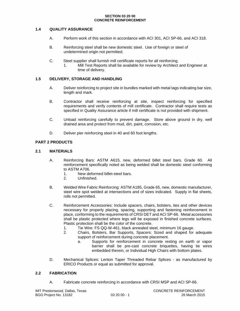
SECTION 03 20 00 CONCRETE REINFORCEMENT
IMT Prestonwood, Dallas, Texas CONCRETE REINFORCEMENT BGO Project No. 13182 03 20 00 - 1 26 March 2015
1.4 QUALITY ASSURANCE
A. Perform work of this section in accordance with ACI 301, ACI SP-66, and ACI 318.
B. Reinforcing steel shall be new domestic steel. Use of foreign or steel of undetermined origin not permitted.
C. Steel supplier shall furnish mill certificate reports for all reinforcing.
1. Mill Test Reports shall be available for review by Architect and Engineer at time of delivery.
1.5 DELIVERY, STORAGE AND HANDLING
A. Deliver reinforcing to project site in bundles marked with metal tags indicating bar size, length and mark.
B. Contractor shall receive reinforcing at site, inspect reinforcing for specified
requirements and verify contents of mill certificate. Contractor shall require tests as specified in Quality Assurance article if mill certificate is not provided with shipment.
C. Unload reinforcing carefully to prevent damage. Store above ground in dry, well
drained area and protect from mud, dirt, paint, corrosion, etc. D. Deliver pier reinforcing steel in 40 and 60 foot lengths.
PART 2 PRODUCTS 2.1 MATERIALS
A. Reinforcing Bars: ASTM A615, new, deformed billet steel bars, Grade 60. All reinforcement specifically noted as being welded shall be domestic steel conforming to ASTM A706. 1. New deformed billet-steel bars. 2. Unfinished.
B. Welded Wire Fabric Reinforcing: ASTM A185, Grade 65, new, domestic manufacturer,
steel wire spot welded at intersections and of sizes indicated. Supply in flat sheets, rolls not permitted.
C. Reinforcement Accessories: Include spacers, chairs, bolsters, ties and other devices
necessary for properly placing, spacing, supporting and fastening reinforcement in place, conforming to the requirements of CRSI DET and ACI SP-66. Metal accessories shall be plastic protected where legs will be exposed in finished concrete surfaces. Plastic protection shall be the color of the concrete. 1. Tie Wire: FS QQ-W-461, black annealed steel, minimum 16 gauge. 2. Chairs, Bolsters, Bar Supports, Spacers: Sized and shaped for adequate
support of reinforcement during concrete placement. a. Supports for reinforcement in concrete resting on earth or vapor
barrier shall be pre-cast concrete briquettes, having tie wires embedded therein, or Individual High Chairs with bottom plates.
D. Mechanical Splices: Lenton Taper Threaded Rebar Splices - as manufactured by
ERICO Products or equal as submitted for approval. 2.2 FABRICATION
A. Fabricate concrete reinforcing in accordance with CRSI MSP and ACI SP-66.
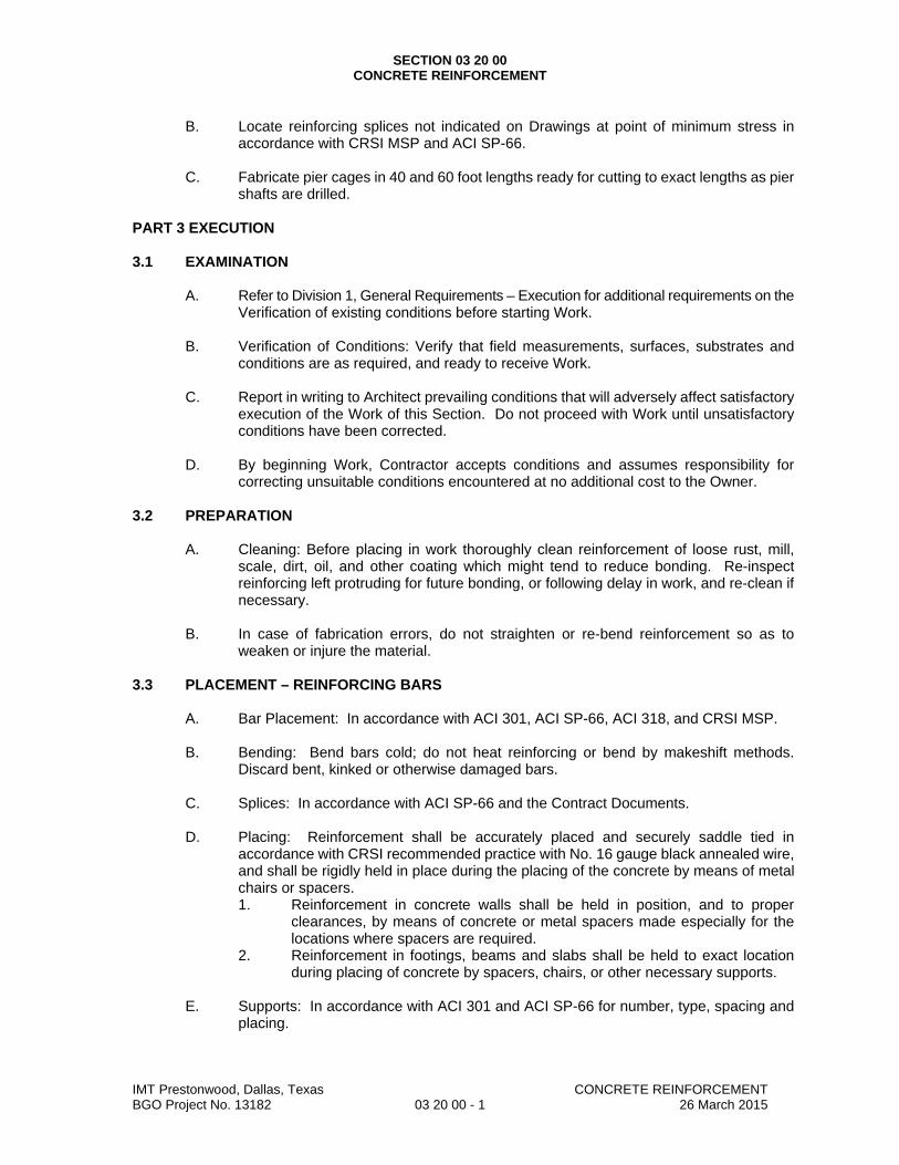
SECTION 03 20 00 CONCRETE REINFORCEMENT
IMT Prestonwood, Dallas, Texas CONCRETE REINFORCEMENT BGO Project No. 13182 03 20 00 - 1 26 March 2015
B. Locate reinforcing splices not indicated on Drawings at point of minimum stress in
accordance with CRSI MSP and ACI SP-66.
C. Fabricate pier cages in 40 and 60 foot lengths ready for cutting to exact lengths as pier shafts are drilled.
PART 3 EXECUTION 3.1 EXAMINATION
A. Refer to Division 1, General Requirements – Execution for additional requirements on the
Verification of existing conditions before starting Work. B. Verification of Conditions: Verify that field measurements, surfaces, substrates and
conditions are as required, and ready to receive Work. C. Report in writing to Architect prevailing conditions that will adversely affect satisfactory
execution of the Work of this Section. Do not proceed with Work until unsatisfactory conditions have been corrected.
D. By beginning Work, Contractor accepts conditions and assumes responsibility for
correcting unsuitable conditions encountered at no additional cost to the Owner. 3.2 PREPARATION
A. Cleaning: Before placing in work thoroughly clean reinforcement of loose rust, mill, scale, dirt, oil, and other coating which might tend to reduce bonding. Re-inspect reinforcing left protruding for future bonding, or following delay in work, and re-clean if necessary.
B. In case of fabrication errors, do not straighten or re-bend reinforcement so as to
weaken or injure the material. 3.3 PLACEMENT – REINFORCING BARS
A. Bar Placement: In accordance with ACI 301, ACI SP-66, ACI 318, and CRSI MSP.
B. Bending: Bend bars cold; do not heat reinforcing or bend by makeshift methods. Discard bent, kinked or otherwise damaged bars.
C. Splices: In accordance with ACI SP-66 and the Contract Documents.
D. Placing: Reinforcement shall be accurately placed and securely saddle tied in
accordance with CRSI recommended practice with No. 16 gauge black annealed wire, and shall be rigidly held in place during the placing of the concrete by means of metal chairs or spacers. 1. Reinforcement in concrete walls shall be held in position, and to proper
clearances, by means of concrete or metal spacers made especially for the locations where spacers are required.
2. Reinforcement in footings, beams and slabs shall be held to exact location during placing of concrete by spacers, chairs, or other necessary supports.
E. Supports: In accordance with ACI 301 and ACI SP-66 for number, type, spacing and
placing.
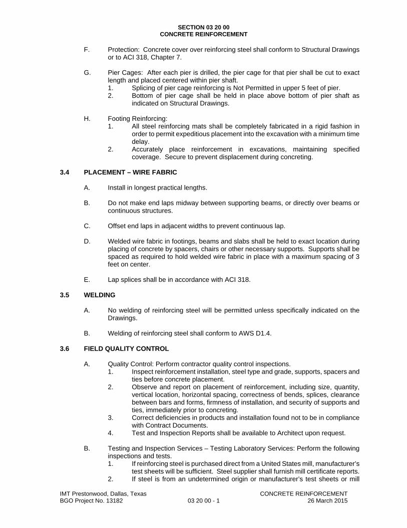
SECTION 03 20 00 CONCRETE REINFORCEMENT
IMT Prestonwood, Dallas, Texas CONCRETE REINFORCEMENT BGO Project No. 13182 03 20 00 - 1 26 March 2015
F. Protection: Concrete cover over reinforcing steel shall conform to Structural Drawings or to ACI 318, Chapter 7.
G. Pier Cages: After each pier is drilled, the pier cage for that pier shall be cut to exact
length and placed centered within pier shaft. 1. Splicing of pier cage reinforcing is Not Permitted in upper 5 feet of pier. 2. Bottom of pier cage shall be held in place above bottom of pier shaft as
indicated on Structural Drawings.
H. Footing Reinforcing: 1. All steel reinforcing mats shall be completely fabricated in a rigid fashion in
order to permit expeditious placement into the excavation with a minimum time delay.
2. Accurately place reinforcement in excavations, maintaining specified coverage. Secure to prevent displacement during concreting.
3.4 PLACEMENT – WIRE FABRIC
A. Install in longest practical lengths.
B. Do not make end laps midway between supporting beams, or directly over beams or continuous structures.
C. Offset end laps in adjacent widths to prevent continuous lap.
D. Welded wire fabric in footings, beams and slabs shall be held to exact location during
placing of concrete by spacers, chairs or other necessary supports. Supports shall be spaced as required to hold welded wire fabric in place with a maximum spacing of 3 feet on center.
E. Lap splices shall be in accordance with ACI 318.
3.5 WELDING
A. No welding of reinforcing steel will be permitted unless specifically indicated on the Drawings.
B. Welding of reinforcing steel shall conform to AWS D1.4.
3.6 FIELD QUALITY CONTROL
A. Quality Control: Perform contractor quality control inspections. 1. Inspect reinforcement installation, steel type and grade, supports, spacers and
ties before concrete placement. 2. Observe and report on placement of reinforcement, including size, quantity,
vertical location, horizontal spacing, correctness of bends, splices, clearance between bars and forms, firmness of installation, and security of supports and ties, immediately prior to concreting.
3. Correct deficiencies in products and installation found not to be in compliance with Contract Documents.
4. Test and Inspection Reports shall be available to Architect upon request.
B. Testing and Inspection Services – Testing Laboratory Services: Perform the following inspections and tests. 1. If reinforcing steel is purchased direct from a United States mill, manufacturer’s
test sheets will be sufficient. Steel supplier shall furnish mill certificate reports. 2. If steel is from an undetermined origin or manufacturer’s test sheets or mill

SECTION 03 20 00 CONCRETE REINFORCEMENT
IMT Prestonwood, Dallas, Texas CONCRETE REINFORCEMENT BGO Project No. 13182 03 20 00 - 1 26 March 2015
certificate reports are unavailable, perform tension and bending tests on three separate samples of each size of bar for every five tons of each type of steel as specified in the appropriate ASTM Specifications. Contractor shall furnish all material for testing and pay for all such tests.
END OF SECTION

SECTION 03 30 00 CAST-IN-PLACE CONCRETE
IMT Prestonwood, Dallas, Texas CAST-IN-PLACE CONCRETE BGO Project No. 13182 03 30 00 - 1 26 March 2015
PART 1 GENERAL 1.1 SUMMARY
A. Section Includes: 1. Furnish all labor, materials, services and equipment as required in conjunction
with or properly incidental to placing of concrete as described herein and/or as shown on the Drawings.
2. Includes all cast-in-place concrete building members, and MEP equipment pads. Includes mixing, placing, and finishing.
B. Related Documents:
1. Drawings and general provisions of Contract, including General and Supplementary Conditions and Division 1, General Requirements, apply to the Work of this section.
C. Related Sections:
1. Section 03 30 50 – Vapor Barrier. 2. Section 03 11 00 – Concrete Forming. 3. Section 03 11 06 – Void Forms. 4. Section 03 20 00 – Concrete Reinforcement.
1.2 REFERENCES
A. American Concrete Institute (ACI): 1. ACI 211.1, Standard Practice for Selecting Proportions of Normal,
Heavyweight and Mass Concrete. 2. ACI 301, Specifications for Structural Concrete for Buildings. 3. ACI 302.2R, Guide for Concrete Floor and Slab Construction. 4. ACI 304R, Guide for Measuring, Mixing, Transporting and Placing Concrete. 5. ACI 305R, Hot Weather Concreting. 6. ACI 306R, Cold Weather Concreting. 7. ACI 308, Standard Practice for Concrete Curing. 8. ACI 309, Standard Practice for Consolidation of Concrete. 9. ACI 311, ACI Manual of Concrete Inspection. 10. ACI 318, Building Code Requirements for Structural Concrete.
B. American Society for Testing and Materials (ASTM): 1. ASTM C31, Standard Practice for Making and Curing Concrete Test
Specimens in the Field. 2. ASTM C33, Standard Specification for Concrete Aggregate. 3. ASTM C39, Standard Test Method for Compressive Strength of Cylindrical
Concrete Specimens. 4. ASTM C94, Standard Specification for Ready-Mix Concrete. 5. ASTM C136, Standard Method for Sieve Analysis of Fine and Coarse
Aggregates. 6. ASTM C143, Standard Specification for Slump of Portland Cement Concrete. 7. ASTM C150, Standard Specification for Portland Cement. 8. ASTM C172, Sampling of Freshly Mixed Concrete. 9. ASTM C260, Standard Specification for Air-Entraining Admixtures. 10. ASTM C330, Standard Specification for Lightweight Aggregates for Structural
Concrete. 11. ASTM C494, Standard Specification for Chemical Admixtures for Concrete. 12. ASTM C618, Standard Specification for Fly Ash and Raw or Calcined Natural
Pozzolan for Use in Concrete.
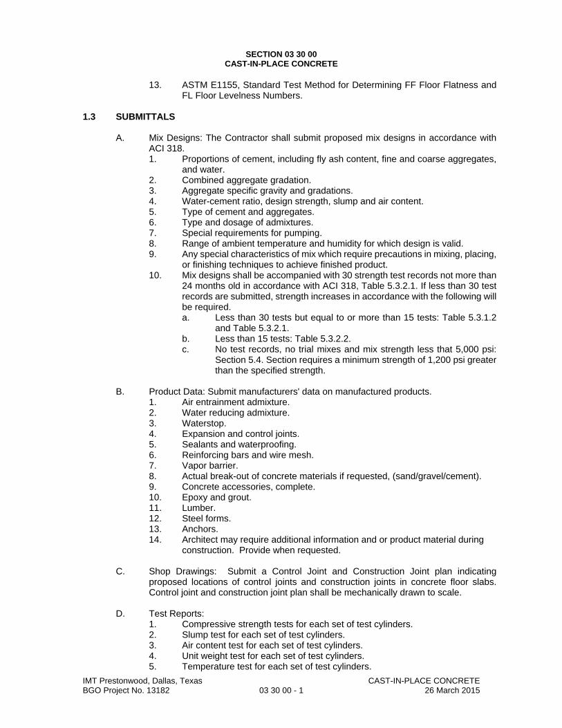
SECTION 03 30 00 CAST-IN-PLACE CONCRETE
IMT Prestonwood, Dallas, Texas CAST-IN-PLACE CONCRETE BGO Project No. 13182 03 30 00 - 1 26 March 2015
13. ASTM E1155, Standard Test Method for Determining FF Floor Flatness and FL Floor Levelness Numbers.
1.3 SUBMITTALS
A. Mix Designs: The Contractor shall submit proposed mix designs in accordance with ACI 318. 1. Proportions of cement, including fly ash content, fine and coarse aggregates,
and water. 2. Combined aggregate gradation. 3. Aggregate specific gravity and gradations. 4. Water-cement ratio, design strength, slump and air content. 5. Type of cement and aggregates. 6. Type and dosage of admixtures. 7. Special requirements for pumping. 8. Range of ambient temperature and humidity for which design is valid. 9. Any special characteristics of mix which require precautions in mixing, placing,
or finishing techniques to achieve finished product. 10. Mix designs shall be accompanied with 30 strength test records not more than
24 months old in accordance with ACI 318, Table 5.3.2.1. If less than 30 test records are submitted, strength increases in accordance with the following will be required. a. Less than 30 tests but equal to or more than 15 tests: Table 5.3.1.2
and Table 5.3.2.1. b. Less than 15 tests: Table 5.3.2.2.
c. No test records, no trial mixes and mix strength less that 5,000 psi: Section 5.4. Section requires a minimum strength of 1,200 psi greater than the specified strength.
B. Product Data: Submit manufacturers' data on manufactured products.
1. Air entrainment admixture. 2. Water reducing admixture. 3. Waterstop. 4. Expansion and control joints. 5. Sealants and waterproofing. 6. Reinforcing bars and wire mesh. 7. Vapor barrier. 8. Actual break-out of concrete materials if requested, (sand/gravel/cement). 9. Concrete accessories, complete. 10. Epoxy and grout. 11. Lumber. 12. Steel forms. 13. Anchors. 14. Architect may require additional information and or product material during
construction. Provide when requested.
C. Shop Drawings: Submit a Control Joint and Construction Joint plan indicating proposed locations of control joints and construction joints in concrete floor slabs. Control joint and construction joint plan shall be mechanically drawn to scale.
D. Test Reports:
1. Compressive strength tests for each set of test cylinders. 2. Slump test for each set of test cylinders. 3. Air content test for each set of test cylinders. 4. Unit weight test for each set of test cylinders. 5. Temperature test for each set of test cylinders.
SECTION 03 30 00 CAST-IN-PLACE CONCRETE
IMT Prestonwood, Dallas, Texas CAST-IN-PLACE CONCRETE BGO Project No. 13182 03 30 00 - 1 26 March 2015
6. Floor Flatness and Levelness tests.
E. Special Inspection Reports: 1. Special Inspection Reports: Submit inspection reports directly to Building
Official and Architect from Independent Special Inspector with copy to Contractor in accordance with requirements of International Building Code, Section 1704 - Special Inspections, if required by the Building Official.
1.4 QUALITY ASSURANCE
A. Source Quality Control: 1. Concrete production facilities shall meet the requirement for certification by the
National Ready Mixed Concrete Association. 2. Concrete batchers shall be completely interlocked semi-automatic or
automatic batchers, as defined by the Concrete Plan Manufacturer’s Bureau. 3. Concrete batchers shall have graphic, digital, or photographic recorders, which
shall register both empty balance and total weight (or volume of water or admixture) of each batched material, time to the nearest minute, date, identification of batch, and numerical count of each batch. Copies of the record shall be furnished to the Testing Laboratory.
B. Qualifications:
1. Installer: Company specializing in concrete work specified with minimum five (5) years documented experience.
2. Concrete Samples and Slump Tests: a. Testing Agency: Sample cylinders taken and slump test performed by
Independent Testing Laboratory personnel. b. Contractor: Sample cylinders and slump tests may be taken by
Contractor if taken by person trained in concrete sampling and testing, and holding a current ACI Concrete Laboratory Technician - Grade 1 Certification. Submit certification to Architect as part of Qualification Documentation.
C. Perform work of this section in accordance with ACI 301 and ACI 318. D. Acquire cement from same source and aggregate from same source for entire project.
E. Concrete Floor Slab Moisture Emission and Acidity:
1. Do not place or permit placement of underslab granular mat if building area subgrade pad is wet. Place granular mat only when building area subgrade pad area is dry.
2. Do not place or permit placement of underslab vapor barrier over granular mat if granular mat is wet. Place underslab vapor barrier only when granular mat is dry. Refer to Section 03 30 50 - Vapor Barrier.
3. Do not add water into transit-mixer at Project site before concrete placement unless instructed by Independent Testing Laboratory representative as specified in this Section.
4. Concrete Contractor is responsible for properly curing concrete floor slab to provide concrete floor slab with moisture emission and acidity test results conforming to each floor material manufacturer requirements for moisture emission and acidity as specified in each floor material specification section when tested in accordance with ASTM F 1869. Refer to each floor material specification section for specific requirements.
1.5 PRODUCT DELIVERY, STORAGE, HANDLING AND SEQUENCING

SECTION 03 30 00 CAST-IN-PLACE CONCRETE
IMT Prestonwood, Dallas, Texas CAST-IN-PLACE CONCRETE BGO Project No. 13182 03 30 00 - 1 26 March 2015
A. Mix and deliver concrete to project ready-mixed in accordance with ASTM C94.
B. Schedule delivery so that continuity of any pour will not be interrupted for over 15 minutes.
C. Place concrete on site within 60 minutes after proportioning materials at batch plant.
D. Coordinate Work of this Section with work of other Sections as required to properly
execute the Work and as necessary to maintain satisfactory progress of the work of other Sections.
1.6 PROJECT CONDITIONS
A. Hot Weather Concreting: 1. Follow ACI 301 and ACI 305. 2. Provide retarding type admixture conforming to ASTM C494, Type A or D in
accordance with manufacturer’s recommendations. 3. Maximum concrete temperature shall not exceed 95 degrees F at time of
placement. a. With prior approval, Concrete with temperatures above 90 degrees F
shall be placed only if a high range water reducer (super plasticizer) is added to the mix as directed the Testing Laboratory to maintain the specified slump during placement.
B. Cold Weather Concreting: Protect concrete work from physical damage or reduced
strength which could be caused by frost, freezing actions, or low temperatures. 1. Follow ACI 301 and ACI 306R. 2. When ambient temperature at site is below 40 degrees F or is expected to fall
to that temperature within ensuing 24 hours, measures shall be taken so that the temperature of concrete will be between 55 degrees F and 85 degrees F at time of placement.
3. Once the concrete has been placed, it must be maintained at a temperature above 50 degrees F for minimum of 72 hours after placing.
4. Temperature Changes: Maintain changes in concrete temperature as uniformly as possible, but in no case exceed change of 5 degrees F per hour or 25 degrees F in any 24 hour period.
5. Combustion heaters shall not be used during the first 48 hours without precautions to prevent exposure of concrete and workmen to exhaust gases containing carbon dioxide and/or carbon monoxide.
C. Select admixture type (normal, retarder, or high early) best suited for concrete at the
time of placing. The use of calcium chloride is specifically prohibited. PART 2 PRODUCTS 2.1 FORMWORK
A. Standard Formwork: Specified in Section 03 11 00 - Concrete Forming. 2.2 REINFORCEMENT
A. Specified in Section 03 20 00 - Concrete Reinforcement. 2.3 CONCRETE MATERIALS
A. Cement/Fly Ash:

SECTION 03 30 00 CAST-IN-PLACE CONCRETE
IMT Prestonwood, Dallas, Texas CAST-IN-PLACE CONCRETE BGO Project No. 13182 03 30 00 - 1 26 March 2015
1. Portland Cement, Type I, conforming to the requirements of ASTM C150. 2. Fly Ash, Class C or F, conforming to the requirements of ASTM C618. The
use of Fly Ash shall be subject to review by the Architect. Where Fly Ash is used in the mix design, Fly Ash shall comprise no more than 30% by weight of the total cementitious material in the mix. Fly Ash shall not be used in architecturally exposed concrete.
B. Aggregate:
1. Fine: ASTM C33; clean, hard, durable, uncoated, natural sand, washed, free of silt, loam or clay.
2. Coarse: ASTM C33; hard, durable, uncoated gravel, washed and screened without adherent coatings.
3. Coarse aggregate for structural lightweight concrete shall conform to the applicable requirements of ASTM C330 suitably processed, washed and screened, and shall consist of durable particles without coatings. Gradation in accordance with Size Designation 3/4 inch to No. 4, Table 1, ASTM C330.
4. Grading shall be in accordance with “Standard Method for Sieve Analysis of Sieve and Coarse Aggregates” (ASTM C136).
C. Water: ASTM C94, Paragraph 4.1.3; potable, clean and free from oil, acid and injurious
amount of vegetable matter, alkalies, and other impurities. 2.4 ADMIXTURES
A. Cement-dispersing, water-reducing types. Admixtures shall conform to ASTM C494, Type A or D, and shall be used strictly in accordance with manufacturer’s recommendations and as determined by the Testing Laboratory. Admixture shall not discolor concrete or in any way affect the appearance of the concrete. 1. High-range water reducing admixture conforming to ASTM C494, Type F, may
be used.
B. An air-entraining admixture conforming to ASTM C260 shall be used as required.
C. Use of calcium chloride is specifically prohibited. 2.5 CONCRETE ACCESSORIES
A. Non-Shrink Grout: Premixed, non-shrink, non-metallic, cement grout requiring only addition of water. Minimum compressive strength of 5,000 psi at 7-days and 7,500 psi at 28 days when placed at a plastic consistency of 115% flow factor.
B. Bonding Agent: ASTM C 1059, Type II acrylic non-redispersable type.
C. Vapor Barrier: Specified in Section 03 30 50 - Vapor Barrier.
D. Epoxy Adhesive: ASTM C 881, two-component material suitable for use on dry or
damp surfaces. Provide material type, grade, and class to suit Project requirements.
E. Joint Filler: Non-extruding, resilient asphalt impregnated fiberboard or felt, complying with ASTM D 1751, thickness as indicated on Drawings and width/depth as indicated.
F. Construction Joint Devices: Steel slab construction joints not permitted.
G. Sealant and Primer: Refer to Division 7: Thermal and Moisture Protection, for additional
information regarding sealant and primer.

SECTION 03 30 00 CAST-IN-PLACE CONCRETE
IMT Prestonwood, Dallas, Texas CAST-IN-PLACE CONCRETE BGO Project No. 13182 03 30 00 - 1 26 March 2015
H. Miscellaneous Structural Metals Associated with Structural Concrete: 1. All structural steel pieces including miscellaneous structural metals placed in
concrete exposed to weather, in permanent contact with soil, or accessible to salt intrusion shall be hot dipped galvanized in accordance with ASTM A123.
2. All structural steel pieces embedded in concrete shall conform to ASTM A36, unless noted otherwise on the Drawings.
3. Welding of inserts, anchors and other steel pieces used in conjunction with structural concrete shall conform to AWS D1.1.
4. Welding of reinforcing steel used in conjunction with structural concrete shall conform to AWS D1.4.
5. Headed stud anchors shall conform to ASTM A108, minimum tensile strength 60,000 PSI.
6. Concrete expansion anchors shall be wedge-type anchors, meeting the requirements of Federal Specifications FF-S-325, Group II, Type 4, Class 1, plated in accordance with Federal Specification QQ-Z-325C, Type II, Class 3. Size and location shall be as indicated on the Drawings.
I. Cure and Seal Compound: shall comply with ASTM C309. For concrete floors not to
receive other finishes, use Ashford Formula to cure, seal and harden concrete. 2.6 CONCRETE MIX DESIGN
A. Strength: Concrete is classified and specified by ultimate compressive strength (f’c) at the age of 28 days.
B. Design concrete to ultimate compressive strengths (f’c) indicated on the Drawings.
C. Proportioning Concrete: Proportions of cement, aggregate, and water to attain required
plasticity and compressive strength shall be in accordance with ACI 318. Do not make changes in proportions without submitting proposed changes to Testing Laboratory for evaluation. 1. Mix designs furnished by the concrete supplier, and accompanied by test data
showing an acceptable strength history meeting the requirements of Method 2 as specified in section 3.8 of ACI 301. a. Temperature of concrete in test data shall be in within 5 degrees F of
maximum temperature specified for this project. b. Strengths indicated in test data shall be in accordance with ACI 318,
paragraphs 5.3 and 5.4. c. The specified strength of concrete used in supporting test data shall
vary no more than 500 PSI plus or minus from that specified for this project.
2. The Testing Laboratory shall keep a strength history record of all concrete for the duration of the project as specified in this section.
PART 3 EXECUTION 3.1 GENERAL
A. Classes of Concrete and Usage: Concrete of the several classes required shall have the characteristics shown on the Drawings.
B. Verification of Conditions: Verify that field measurements, surfaces, substrates and
conditions are as required, and ready to receive Work. 1. Verify lines, levels, and dimensions before proceeding with work of this
section. 2. Verify that screeding equipment is calibrated to provide concrete slab to

SECTION 03 30 00 CAST-IN-PLACE CONCRETE
IMT Prestonwood, Dallas, Texas CAST-IN-PLACE CONCRETE BGO Project No. 13182 03 30 00 - 1 26 March 2015
specified flatness and levelness requirements.
C. Inserts: Give the various trades and subcontractors ample notification and opportunity to furnish any and all anchors, nailers, pipes, conduits, boxes, inserts, thimbles, sleeves, frame vents, wires, supports, or other items required to be built into the concrete by the provisions of the Drawings or of the Specification governing the work of such trades and subcontractors, or as it may be necessary for the proper execution of their work. Obtain suitable templates or instructions for the installation of such items which are required to be placed in the forms.
D. Mixing:
1. Transit-mixed concrete conforming to the requirements of ASTM C94 and ACI 304 shall be used in lieu of concrete mixed at the job site. Concrete shall not be transported or used in any case after a period in excess of ninety (90) minutes has elapsed after the introduction of water into the mixer.
2. Indiscriminate addition of water to increase slump of concrete is prohibited. Add water only at the direction the Testing Laboratory. No water shall be added which increases the water cement ratio of the concrete in excess of the water cement ratio indicated on the approved mix design. At the direction of the Testing Laboratory the addition of a high range water reducing admixture may be used to retemper concrete.
3. The agency supplying transit-mixed concrete shall have a plant of sufficient capacity and adequate transportation facilities, to assure continuous delivery at the rate required. The frequency of deliveries to the site of the work must be such as to provide for placing the concrete continuously throughout any one (1) pour.
E. By beginning Work, Contractor accepts conditions and assumes responsibility for
correcting unsuitable conditions encountered at no additional cost to the Owner. Costs for correcting unsuitable conditions will be at Contractor’s expense.
3.2 PLACING CONCRETE
A. Place concrete in uniform layers, approximately horizontal, and not more than eighteen inches deep, exercising care to avoid vertical joints or inclined planes. The piling up of concrete in the forms in such a manner as to cause the separation or loss of any of its ingredients will not be permitted. Concrete which has partially set or hardened shall not under any circumstances, be deposited in the Work.
B. Place concrete in the forms as nearly in its final position as is practical to avoid
rehandling. Deposit concrete in horizontal layers maximum 24 inches and in a manner to avoid inclined construction joints. Exercise special care to prevent splashing the forms or reinforcement with concrete. Remove any hardened or partially hardened concrete which has accumulated on the forms or reinforcement before the work proceeds. Do no place concrete on previously deposited concrete which has hardened sufficiently to cause the formation of seams or planes of weakness within the respective member of section, except as hereinafter specified.
C. Placing Concrete Slabs: Place and consolidate concrete slabs in continuous
operation, within limits of construction joints, until completion of panel or section placement. 1. Consolidate concrete during placement operations so that concrete is
thoroughly worked around reinforcement, other embedded items and into corners.
SECTION 03 30 00 CAST-IN-PLACE CONCRETE
IMT Prestonwood, Dallas, Texas CAST-IN-PLACE CONCRETE BGO Project No. 13182 03 30 00 - 1 26 March 2015
2. Bring slab surfaces to correct level with straightedge and strike off. Use bull floats or derbies to smooth surface free of humps or hollows. Do not disturb slab surfaces before beginning finishing operations.
3. Maintain reinforcing in proper position on chairs during concrete placement. D. Do not permit concrete to drop freely any distance greater than five feet (5’). Where
longer drops are necessary, use a chute, tremie, or other acceptable conveyance to assist the concrete into place without separation. Do not pour directly into any excavations where water is standing.
E. Concrete shall be placed as soon as practical after footing excavations have been
completed. If concrete is not to be placed within eight hours, a 3 inch thick lean concrete “working mat” shall be placed over the bearing surface of the exposed subgrade soils within four hours after the excavation has been completed. The “working mat” shall not extend above the bottom elevation of the spread or continuous footing.
F. Vibration: As soon as concrete is deposited, thoroughly agitate same by means of
mechanical vibrators and suitable hand tools, so manipulated as to work the mixture well into all parts and corners of the forms and entirely around the reinforcement and inserts. Mechanical vibrators shall maintain frequencies in accordance with the recommendations of ACI 309, Table 5.1.4, and shall be operated by competent workmen. Over vibrating and use of vibrators to transport concrete within forms shall not be allowed. A spare vibrator shall be kept on job site during all concrete placing operations.
G. Conveying Concrete: Convey concrete from the mixer to the place of final deposit by
methods which will prevent the separation or loss of the ingredients. Concrete to be conveyed by pumping shall be submitted to the Testing Laboratory for evaluation for each class of concrete shall be taken at the discharge end of the pumping equipment.
H. Equipment for chuting, pumping and pneumatically conveying concrete shall be of
such size and design as to assure a practically continuous flow of concrete at the delivery end without separation of the materials. The use of gravity-flow or aluminum chutes or conveyors for transporting concrete horizontally will not be permitted.
I. Bonding: Before depositing any new concrete on or against previously deposited
concrete which has partially or entirely set, the surface of the latter shall be thoroughly roughened and cleaned of all foreign matter, scum and laitance. Coat surface of previously deposited concrete with a bonding agent per manufacturer’s direction.
J. Construction Joints: Except as otherwise specifically indicated on the Drawings, each
concrete member shall be considered as a single unit of operation and all concrete for the same shall be placed continuously in order that such unit will be monolithic in construction. Should construction joints prove to be absolutely unavoidable, same shall be located at or near the midpoints of spans. Additional construction joints shall not be made under any circumstances without prior review by the Architect and Structural Engineer.
K. Protect all freshly placed concrete from washing by rain, flowing water etc. Do not
allow the concrete to dry out from the time it is deposited in the forms until the expiration of the curing period.
L. Refer to structural drawings for column base plate and other structural grouting
requirements.

SECTION 03 30 00 CAST-IN-PLACE CONCRETE
IMT Prestonwood, Dallas, Texas CAST-IN-PLACE CONCRETE BGO Project No. 13182 03 30 00 - 1 26 March 2015
M. Grout shall be mixed only in such quantities as are needed for immediate use. No retempering shall be permitted and materials which have been mixed for a period exceeding thirty (30) minutes shall in no case be used upon any portion of the work.
N. Imperfect or damaged work, or any material damaged or determined to be defective
before final completion and acceptance of the entire job, shall be satisfactorily replaced at the Contractor’s expense and shall be in conformity with all of the requirements of the Contract Documents. Removal and replacement of concrete work shall be done in such a manner as not to impair the appearance or strength of the structure in any way.
O. Cleaning: Upon completion of the work, all forms, equipment, protective coverings and
any rubbish resulting therefrom shall be removed from the premises. Finished concrete surfaces shall be left in clean and perfect condition, satisfactory to the Owner. Sweep with an ordinary broom and remove all mortar, concrete droppings, loose dirt, mud, etc.
P. Separate slabs on grade from vertical surfaces with joint filler.
Q. Place joint filler in floor slab pattern placement sequence. Set top to required
elevations. Secure to resist movement by wet concrete.
R. Extend joint filler from bottom of slab to within 1/2 inch of finished slab surface.
S. Locate construction joints in coordination with floor slab pattern placement sequence. Provide keyways minimum 1-1/2 inches deep in walls and slabs and between walls and footings. 1. Place construction joints perpendicular to main reinforcement. Continue
reinforcement across construction joints, unless indicated otherwise. T. Screed floors level, maintaining surface Flatness and Levelness in accordance with
the Architectural requirements. 3.3 FIELD QUALITY CONTROL
A. Quality Control: Quality Control Representatives shall perform contractor quality control inspections. 1. Inspect concrete placement, concrete pumping, leveling and screeding
operations. 2. Check floor slab for compliance with specified Floor Flatness and Floor
Levelness. 3. Document preparatory, initial and follow-up inspection in Contractor’s Test and
Inspection Reports. 4. Test and Inspection Reports shall be available to Architect upon request.
B. Testing and Inspection Services:
1. Perform the following tests. a. Compressive Strength Tests: Perform minimum one (1) test for each
100 cubic yards or fraction thereof, of each mix design of concrete placed in any one (1) day. Specimens for pumped concrete shall be taken at the discharge end of pumping equipment. 1) Test Cylinders: Mold and cure four (4) 6”x12” or five (5)
4”X8” specimens from each set of samples in accordance with ASTM C 31.
2) Tests: Each set of four (4) 6”x12” or five (5) 4”X8” cylinders.

SECTION 03 30 00 CAST-IN-PLACE CONCRETE
IMT Prestonwood, Dallas, Texas CAST-IN-PLACE CONCRETE BGO Project No. 13182 03 30 00 - 1 26 March 2015
One (1) 6”X12” or 4”X8” cylinder at seven (7) days for information. Two (2) 6”x12” or Three (3) 4”x8” cylinders at twenty-eight (28) days. One (1) 6”X12” or 4”X8” cylinder held in reserve for minimum fifty-six (56) days tested as directed.
b. Slump Tests: Perform one (1) slump test for each set of samples in accordance with ASTM C 143 or as directed by Architect.
c. Air Content Tests: Perform one (1) test for each set of samples in accordance with ASTM C 231 or ASTM C 173.
d. Unit Weight Tests: Perform one (1) test for each set of samples in accordance with ASTM C 138.
e. Temperature Tests: Measure temperature of concrete sample for each set of samples.
f. Floor Flatness and Levelness Tests: Perform tests using measuring equipment in accordance with ASTM E 1155.
g. Test Results: Testing Laboratory shall report test results in writing to Architect and Contractor within twenty-four (24) hours of test.
2. Inspections: Perform the following inspections. a. Batch Inspection and Monitoring Water: Inspect each batch of
concrete, monitor addition of mixing water to assure uniform consistency from truck to truck. Check mixing from mixers before mix begins to set and within time limits set forth in ASTM C94. 1) Monitor addition of water to concrete at job site and length of
time concrete is allowed to remain in truck during placement. 2) Certify each delivery ticket indicating class of concrete
delivered, amount of water added and time at which cement and aggregate was discharged into truck, and time at which concrete was discharged from truck.
3) Water additions during transit shall be permitted in accordance with ASTM C94/94M, with trucks equipped with automated slump and water management systems, such as Verifi Slump Management System or approved equal.
3. Test Procedures: a. Sample Technician: Test cylinders and slump tests performed only by
person holding a current ACI Concrete Laboratory Technician - Grade 1 Certification.
b. Sampling: Secure composite samples in accordance with ASTM C 172. Each sample shall be obtained from a different batch of concrete on a random basis, avoiding any selection of the test batch other than by a number selected at random before commencement of concrete placement.
c. Pumped Concrete Samples: Specimens for pumped concrete shall be taken at the discharge end of pumping equipment.
d. Tests of concrete and concrete materials may be performed at any time to ensure conformance with specified requirements.
4. Test Reports: a. Submit proposed mix design of each class of concrete to inspection
and testing firm for review prior to commencement of concrete operations.
b. Any deviations from the requirements of ASTM Specifications shall be recorded in the test report. Test concrete specimens in accordance with ASTM C 39.
c. Should strength of concrete fall below the minimum, then additional tests, including load tests, may be required. These tests, if required, shall be made at Contractor’s expense and shall be in accordance with
SECTION 03 30 00 CAST-IN-PLACE CONCRETE
IMT Prestonwood, Dallas, Texas CAST-IN-PLACE CONCRETE BGO Project No. 13182 03 30 00 - 1 26 March 2015
ASTM C42 and ACI 318. If tests do not meet applicable requirements, then structure, or any part of structure, shall be removed and replaced at Contractor’s expense.
d. Test reports shall include but not be limited to the following information: 1) Date of concrete placement. 2) Concrete mix identification number or proportions of
ingredients. 3) Truck ticket number. 4) Time test was made. 5) Time of batching. 6) Location of each placement. 7) Slump. 8) Unit weight and air content of concrete sampled. 9) Date and results of strength test.
e. Report promptly to Architect all details of reasons for rejection of any and all quantities of concrete. Give all information concerning locations of the concrete pours, quantities, date of pours, and other pertinent facts concerning concrete represented by the specimens.
f. Any concrete testing requested by the Contractor for early formwork or shoring removal, etc., shall be at Contractor’s expense.
g. Furnish a statistical analysis for each class of concrete placed on the project in accordance with ACI 214 and ACI 318. Information shall be updated and distributed once a month as directed by Architect. Information shall include, but not be limited to, the following: 1) Strength test at seven (7) days. 2) Strength tests at twenty-eight (28) days of two (2) cylinder
averages. 3) 28-day moving average strength tests of last three (3) test
groups. 4) Standard deviation and coefficient of variation based on
twenty-eight (28) day strength tests. 5) Average strength and number of twenty-eight (28) day tests
for most recent month. C. Testing and Inspection Services: Special Inspections.
1. Perform Special Inspections as required by the International Building Code Section 1704 - Special Inspections as indicated on Drawings, if required by the Building Official.
3.4 DEFECTIVE CONCRETE
A. Defective Concrete: Concrete not conforming to required lines, details, dimensions, tolerances or specified requirements.
B. Repair or replacement of defective concrete will be determined by the Architect. The
cost of additional testing shall be borne by Contractor when defective concrete is identified.
C. Do not patch, fill, touch-up, repair or replace exposed concrete except upon express
direction of Architect for each individual area.
D. Failed Strength Tests: If compressive strength tests indicate results below specified strength, Architect may require any or all of the following corrective measures be performed at Contractor's expense. Architect will determine extent of concrete removal if required.

SECTION 03 30 00 CAST-IN-PLACE CONCRETE
IMT Prestonwood, Dallas, Texas CAST-IN-PLACE CONCRETE BGO Project No. 13182 03 30 00 - 1 26 March 2015
1. Change concrete mix. 2. Core test in conformance with ASTM C 42. 3. Load test on portion or portions of structure where test cylinders indicate
concrete is below specified strength. Load testing performed in conformance with ACI 318.
4. Remove and replace concrete below specified strength. END OF SECTION

SECTION 03 30 50 VAPOR BARRIER
IMT Prestonwood, Dallas, Texas VAPOR BARRIER BGO Project No. 13182 03 30 50 - 1 26 March 2015
PART 1 GENERAL 1.1 SUMMARY
A. Section Includes:
1. Furnish all labor, materials, services and equipment as required to place vapor barrier, seam tape, and mastic for installation under concrete slabs.
B. Related documents: 1. Drawings and general provisions of Contract, including General and
Supplementary Conditions and Division 1, General Requirements apply to Work of this section.
C. Related sections:
1. Section 03 11 00 – Concrete Forming. 2. Section 03 30 00 – Cast-in-Place Concrete.
1.2 REFERENCES
A. American Society for Testing and Materials (ASTM): 1. ASTM E 1745-11 Standard Specification for Plastic Water Vapor Retarders
Used in Contact with Soil or Granular Fill Under Concrete Slabs. 2. ASTM E 154-99 (2005) Standard Test Methods for Water Vapor Retarders
Used in Contact with Earth Under Concrete Slabs, on Walls, or as Ground Cover.
3. ASTM E 96-05 Standard Test Methods for Water Vapor Transmission of Materials.
4. ASTM F 1249-06 Standard Test Method for Water Vapor Transmission Rate Through Plastic Film and Sheeting Using a Modulated Infrared Sensor.
5. ASTM E 1643-11 Selection, Design, Installation, and Inspection of Water Vapor Retarders Used in Contact with Earth or Granular Fill Under Concrete Slabs.
B. American Concrete Institute (ACI): 1. ACI 302.2R-06 Guide for Concrete Slabs that Receive Moisture-Sensitive
Flooring Materials. 1.3 SUBMITTALS
A. Quality control/assurance: 1. Summary of test results as per paragraph 8.3 of ASTM E 1745. 2. Manufacturer’s samples, literature. 3. Manufacturer’s installation instructions for placement, seaming and
penetration repair instructions. 1.4 QUALITY ASSURANCE
A. Conform to the requirements of ACI 302.2R.
B. Installer Qualifications: Company specializing in performing under slab vapor barrier installations experienced in use of specified projects with minimum five (5) years documented experience in under slab vapor barrier installation.
C. Stego Manufacturer Regional Representative: Manufacturer representative shall be
on-site the day of vapor barrier placement to instruct contractor in proper vapor barrier

SECTION 03 30 50 VAPOR BARRIER
IMT Prestonwood, Dallas, Texas VAPOR BARRIER BGO Project No. 13182 03 30 50 - 1 26 March 2015
system installation, document installation and verify that proper procedures are followed.
D. Manufacturer Installation Instructions: Contractor shall maintain current copy of vapor
barrier manufacturer published installation instructions in Project Field Office and refer to installation instructions at all times during installation.
1.5 DELIVERY, STORAGE AND HANDLING
A. Division 1, General Requirements - Product Options: Transport, handle, store, and protect Products.
B. Deliver vapor barrier in rolls in manufacturer’s original, unopened, undamaged
containers with identification labels intact.
C. Deliver Material Safety Data Sheet (MSDS) for each material to Project Field Superintendent for Contractor Records.
D. Accept Products on site in manufacturer’s packaging. Inspect for damage. Return
damaged Products and replace with undamaged Products.
E. Project Field Superintendent shall inspect Products immediately upon delivery to Project Site, determine Product conformance with specified requirements and reject Products not complying with specifications. Project Field Superintendent shall direct that non-complying Products be removed from Project Site immediately.
F. Store materials protected from exposure to harmful weather conditions and at
temperature and humidity conditions recommended by manufacturer. PART 2 PRODUCTS 2.1 MATERIALS
A. Where noted on Drawings, 15 mil. Vapor barrier must have all of the following qualities: 1. Permeance of less than 0.01 Perms [grains/(ft2 * hr * inHg)] per ASTM F 1249
or ASTM E 96. 2. Maintain permeance of less than 0.01 Perms [grains/(ft2 *hr * in.Hg)] after
mandatory conditioning tests per ASTM E 154 Sections 8,11,12, and 13. 3. Other performance criteria:
a. Strength: ASTM E 1745 Class A. 4. Vapor barrier products:
a. Stego Wrap 15-mil Vapor Barrier by Stego Industries LLC, (877) 464-7834 www.stegoindustries.com.
B. Where noted on Drawings, 10 mil. Vapor barrier must have all of the following qualities:
1. Permeance of less than 0.03 Perms [grains/(ft2 * hr * inHg)] per ASTM F 1249 or ASTM E 96.
2. Maintain permeance of less than 0.03 Perms [grains/(ft2 *hr * in.Hg)] after mandatory conditioning tests per ASTM E 154 Sections 8,11,12, and 13.
3. Other performance criteria: a. Strength: ASTM E 1745 Class A.
4. Vapor barrier products: a. Stego Wrap 10-mil Vapor Barrier by Stego Industries LLC, (877) 464-
7834 www.stegoindustries.com.
2.2 ACCESSORIES

SECTION 03 30 50 VAPOR BARRIER
IMT Prestonwood, Dallas, Texas VAPOR BARRIER BGO Project No. 13182 03 30 50 - 1 26 March 2015
A. Seam tape: 1. Permeance less than 0.3 perms or lower per ASTM F 1249 or ASTM E 96. 2. Stego Tape by Stego Industries LLC, (877) 464-7834
www.stegoindustries.com.
B. Vapor-proofing mastic: 1. Permeance less than 0.3 perms or lower per ASTM F 1249 or ASTM E 96. 2. Stego Mastic by Stego Industries LLC, (877) 464-7834
www.stegoindustries.com.
C. Pipe Boots: 1. Construct pipe boots from vapor barrier material pressure sensitive tape
and/or mastic per manufacturer’s instructions. PART 3 EXECUTION 3.1 PREPARATION
A. Ensure that base material is approved by Architect or Geotechnical Engineer. 1. Level and compact base material.
3.2 INSTALLATION
A. Install vapor barrier in accordance with manufacturer’s instructions and ASTM E 1643-11. 1. Unroll vapor barrier with the longest dimension parallel with the direction of the
concrete placement. 2. Lap vapor barrier over footings and/or seal to foundation walls. 3. Overlap joints 6 inches and seal with manufacturer’s tape. 4. Seal all penetrations (including pipes) per manufacturer’s instructions. 5. No penetration of the vapor barrier is allowed except for reinforcing steel and
permanent utilities. 6. Repair damaged areas by cutting patches of vapor barrier, overlapping
damaged area 6 inches and taping all sides with tape. 3.3 FIELD QUALITY CONTROL
A. Refer to Division 1, General Requirements – Execution, for additional requirements on a Contractor Quality Control Representative to perform contractor quality control inspections. 1. Inspect installation of vapor barrier, pipe boots, penetration sealing and tear
sealing. 2. Inspect under slab vapor barrier installation, verify that pipes, conduits, floor
drains and other penetrations have been sealed and lap seams taped in conformance with ASTM E 1643-11 and manufacturers published instructions.
3. Document preparatory, initial and follow-up inspection in Contractor’s Test and Inspection Reports.
4. Test and Inspection Reports shall be available to Architect upon request.
B. Stego Manufacturer’s Field Services: 1. Provide technical assistance and guidance for installation of under-slab vapor
barrier system. 2. Inspect installation and certify that product has been furnished and installed in
accordance with manufacturer’s published instructions. a. Prepare and submit inspection report for each inspection made.

SECTION 03 30 50 VAPOR BARRIER
IMT Prestonwood, Dallas, Texas VAPOR BARRIER BGO Project No. 13182 03 30 50 - 1 26 March 2015
C. Correct deficiencies in products and installation found not to be in compliance with Contract Documents.
END OF SECTION
IMT Prestonwood, Dallas, Texas CLEAR CONCRETE SEALER BGO Project No. 13182 033536 - 1 26 March 2015
SECTION 033536
CLEAR CONCRETE SEALER
PART 1 GENERAL
1.1 SUMMARY A. Related Documents: Conditions of the Contract, Division 01 - General Requirements, and Drawings
are applicable to Work of this Section. B. Section Includes:
1. Clear sealer to be applied to all exposed concrete floors inside building.
1.2 SUBMITTALS A. General: Submit in accordance with Section 013000. B. Product Data: Submit manufacturer's technical literature, including chemical properties and
percentage of solids, for each product.
1.3 QUALITY ASSURANCE A. Applicator Qualifications: Performed by firm with 10 years minimum experience in application of sealer
required for Project.
1.4 DELIVERY, STORAGE, AND HANDLING A. Comply with requirements of Division 01. B. Store products above 50°F, but no greater than 85°F, unless otherwise recommended by
manufacturer.
1.5 ENVIRONMENTAL REQUIREMENTS A. Do not apply materials when ambient or substrate surface temperatures are below 40 degrees F or
higher than 100 degrees F. B. Do not apply during inclement weather or when forecasted conditions will not permit compliance with
manufacturer's printed instructions. C. Provide mechanical ventilation during and after application to dissipate fumes if natural ventilation is
insufficient.
1.6 SEQUENCING AND SCHEDULING A. Schedule application of products at proper time intervals after concrete finishing and curing operations. B. Maintain proper moisture content of concrete before, during, and after application of specified products.
PART 2 PRODUCTS
2.1 MATERIALS A. Liquid Membrane-Forming Sealer (for use on concrete floor slabs intended to be left exposed):
1. Acceptable products: a. Dayton Superior Corporation; Ultraseal; EF. b. Substitutions: Submit in accordance with Section 016000.
PART 3 EXECUTION
3.1 EXAMINATION A. Examine conditions and proceed with Work in accordance with Section 014000. B. Verify that surfaces are clean, dry, dust free, and free of efflorescence, oil or other matter detrimental
to sealer application. If required, mechanically abrade surfaces to be coated for proper substrate characteristics.
C. Verify that joint sealant work in adjoining surfaces is complete prior to applications of sealers. Delay application until sealants have cured.
D. Ensure concrete has cured for time period required by manufacturer of product to be applied (28 days minimum before application of products).
E. Verify that damage and defects in concrete surface have been repaired as specified in Section 03 3000 and accepted by Architect.

IMT Prestonwood, Dallas, Texas CLEAR CONCRETE SEALER BGO Project No. 13182 033536 - 2 26 March 2015
3.2 PREPARATION A. Remove loose particles, foreign matter, and oil by method which will not affect sealer application. B. Prepare surfaces in accordance with manufacturer's directions. C. Provide protection as necessary to protect adjacent materials and surfaces from dirt, dust, spillage,
overspray and other surface or physical damage.
3.3 APPLICATION A. General:
1. Provide finishes to match approved samples at locations indicated. 2. Apply materials in accordance with manufacturer's printed instructions.
B. Liquid Membrane-Forming Sealer: 1. Apply sealer using low pressure airless sprayer in single coat at 250 ft/gal (6.0-7.0 WFT)
coverage unless greater amount is recommended by manufacturer to obtain penetration and full coverage.
2. Do not allow flooding or puddling of material on surface. 3. Do not dilute or alter material as packaged. 4. Locations: As indicated on plans and on all exposed concrete flooring inside of building.
3.4 ADJUSTING A. Repair or replace adjacent Work which has been damaged by finishing operations.
3.5 CLEANING A. Clean spillage, overspray, or drift from adjacent surfaces; remove immediately in accordance with
manufacturer's instructions.
3.6 PROTECTION A. Protect finished concrete surfaces from damage by construction equipment, operations and from
adverse weather conditions.
END OF SECTION

SECTION 03 38 16 POST-TENSIONING
IMT Prestonwood, Dallas, Texas POST-TENSIONING BGO Project No. 13182 03 38 16 - 1 26 March 2015
PART 1 GENERAL 1.1 SUMMARY
A. Section Includes: 1. Furnish all labor, materials, services and equipment as required in conjunction
with or properly incidental to completing the Post-Tensioned Concrete as described herein and/or as shown on the Drawings.
B. Related Documents:
1. Drawings and general provisions of Contract, including General and Supplementary Conditions and Division 1, General Requirements, apply to Work of this section.
C. Related Sections:
1. Section 03 11 00 – Concrete Forming. 2. Section 03 20 00 – Concrete Reinforcement. 3. Section 03 30 00 – Cast-in-Place Concrete.
1.2 DEFINITIONS OF TERMS
A. Tendon: The complete assembly consisting of anchorage and prestressing steel with sheathing.
B. Unbonded Tendon: A tendon in which the prestressing steel is permanently free to
move relative to the concrete when the stressing force is being applied.
C. Anchorage: The means by which the stressing force is permanently transmitted from the prestressing steel to the concrete.
D. Prestressing Steel: That element of a post-tensioning tendon which is elongated and
anchored to provide the necessary permanent stressing force.
E. Coating: material used to protect against corrosion and/or lubricate the prestressing steel.
F. Sheathing: Enclosure around the prestressing steel to avoid temporary or permanent
bond between the prestressing steel and the surrounding concrete.
G. Coupling: The means by which the stressing force may be transmitted from one partial-length tendon to another.
1.3 QUALITY ASSURANCE
A. Design Criteria: Post-tensioning design shall conform to ACI 301 and ACI 318 and be supplemented by requirements of Applicable Building Code.
B. Fabrication: The post-tensioning fabricator shall be experienced in the fabrication of
post-tensioning materials.
C. Installer: Company specializing in performing the Work of this Section with minimum five (5) years documented experience.
1.4 SUBMITTALS
A. Submit complete detailed shop and installation drawings prior to performing post-

SECTION 03 38 16 POST-TENSIONING
IMT Prestonwood, Dallas, Texas POST-TENSIONING BGO Project No. 13182 03 38 16 - 1 26 March 2015
tensioned work. Include detailed placing plans indicating: 1. Tendon sizes, locations, and profiles. 2. Supporting hardware details, concrete coverages, anchorage, and stressing
hardware details, including anchorage backup bars if required. 3. Jacking forces and elongations in tendons.
B. Submit complete calculations of losses, initial stresses, and anchorage stresses to
Architect/Engineer for review. Include effects of sequence stressing and effects of restraint by columns on slab or beam shortening where applicable. Calculations shall bear the seal and signature of a Registered Professional Engineer licensed in the State where the project will be built.
C. Provide certification of calibration of jacking equipment used in post-tensioning
operations not less than biweekly or at more frequent intervals if dictated by project conditions.
D. Submit data to show adequacy of the tendon system as confirmed by static and
dynamic conformance tests in accordance with the minimum requirements outlined in PART 2 of this Section. Data from prior tests may be submitted.
E. Submit certified mill test results and typical stress-strain curves for each coil of
prestressing steel used on this project. The typical stress-strain curves shall be obtained by methods consistent with industry standards.
1.5 DELIVERY, STORAGE AND HANDLING
A. Division 1, General Requirements - Product Options: Transport, handle, store, and protect Products.
B. Deliver materials in manufacturer’s original, unopened, undamaged containers with
identification labels intact.
C. Store materials protected from exposure to harmful weather conditions and at temperature and humidity conditions recommended by manufacturer.
D. Mix and deliver concrete to project ready-mixed in accordance with ASTM C 94. E. Schedule delivery so that continuity of any pour will not be interrupted for over 15
minutes. F. Place concrete on site within 90 minutes after proportioning materials at batch plant.
1.6 JOB CONDITIONS
A. Coordination: Coordinate placement of post-tension tendons and post-tensioning operations with construction of formwork, placing of mild steel reinforcement and placing of concrete.
B. Reference Section 03 30 00 – Cast-in-Place Concrete.
PART 2 PRODUCTS 2.1 PRESTRESSING STEEL
A. Wire: Wire used in post-tensioning tendons shall conform to ASTM A421, “Supplement Specifications for Uncoated Low-Relaxation Wire for Prestressed Concrete”. Oil tempered wires shall not be used.

SECTION 03 38 16 POST-TENSIONING
IMT Prestonwood, Dallas, Texas POST-TENSIONING BGO Project No. 13182 03 38 16 - 1 26 March 2015
B. Strand: Strand used in post-tensioning tendons shall conform to ASTM A416,
“Supplement Specification for Uncoated Seven-Wire Low-Relaxation Strand for Prestressed Concrete”.
2.2 UNBONDED TENDONS
A. Anchorage: The anchorages of unbonded tendons shall develop at least 95 percent of the minimum specified ultimate strength of the prestressing steel without exceeding anticipated set. The total elongation under ultimate load of the tendon shall not be less than 2 percent measured in a minimum gauge length of 10 feet.
B. Coating: Unbonded tendons shall have the prestressing steel permanently protected
against corrosion by a properly applied coating of galvanizing, epoxy, grease, wax, plastic, bituminous or other approved material. The coating shall remain ductile and free from cracks and shall not become fluid over the entire operating or anticipated range of temperatures. The coating shall be chemically stable and nonreactive to cement or the sheathing material. The coating material shall adhere to and be continuous over the entire tendon length to be unbonded.
C. Sheathing: The sheathing for unbonded tendons shall have sufficient tensile strength
and water-resistance to resist unrepairable damage and deterioration during transport, storage at jobsite and installation. The sheathing shall prevent the intrusion of cement paste and the escape of coating material. The sheathing may be a continuous tube or spirally wrapped.
D. Couplings: Couplings of unbonded tendons shall be used only at locations specifically
indicated and approved by the Architect. Couplings shall not be used at points of sharp tendon curvature. All couplings shall develop at least 95 percent of the minimum specified ultimate strength of the prestressing steel without exceeding anticipated set. The coupling of tendons shall not reduce the elongation at rupture below the requirements of the tendon itself. Couplings and coupling components shall be enclosed in housing long enough to permit the necessary movements. All the coupling components shall be completely protected with a coating material prior to final encasement in concrete.
E. Multiple Tendons: Tendons composed of multiple strands or wires in a common sheath
should be tensioned simultaneously unless interference between the elements is considered.
F. Ultimate Strength: Ultimate strength for unbonded tendons shall not be taken greater
than the ultimate capacity of the anchorages or couplings. 2.3 STATIC AND DYNAMIC TEST REQUIREMENTS
A. Static Tests: 1. The test assembly shall consist of standard production quality components
and the tendons shall be at least 10 feet long. The test assembly shall be tested in a manner to allow accurate determination of the yield strength, ultimate strength and percent elongation of the complete tendon to insure compliance with this specification. The specimen used for the static test need not be one that has been subjected to dynamic loading.
B. Dynamic Tests:
1. A dynamic test shall be performed on a representative specimen and the tendon shall withstand, without failure, 500,000 cycles from 60 percent to 66 percent of its minimum specified ultimate strength, and also 50 cycles from 40

SECTION 03 38 16 POST-TENSIONING
IMT Prestonwood, Dallas, Texas POST-TENSIONING BGO Project No. 13182 03 38 16 - 1 26 March 2015
percent to 80 percent of its minimum specified ultimate strength. The period of each cycle involves the change from the lower stress level to the upper stress level and back to the lower.
2. The specimen used for the second dynamic test need not be the same used for the first dynamic test. Systems utilizing multiple strands, wires or bras may be tested utilizing a test tendon of small capacity, then the full size tendon. The test tendon shall duplicate the behavior of the full size tendon and generally shall not have less than 10 percent of the capacity of the full size tendon.
PART 3 EXECUTION 3.1 GENERAL (PROVISIONS OF THIS SECTION SHALL BE EXECUTED BY CONTRACTOR)
A. Accomplish stressing by established post-tensioning methods with related equipment and materials proven to produce stressed concrete conforming to the requirements indicated on Drawings and requirements specified herein.
B. Perform stressed concrete operations under direct supervision of Registered
Professional Engineer, licensed in the State where the project will be constructed, skilled and experienced in stressing methods to control operations as required to insure full compliance with the meaning and intent of the Contract Documents.
C. Provide only clean and undamaged materials and properly protect until permanently
installed.
D. Keep end anchorages which will be permanently protected with concrete free of loose rust, grease, oil paint and other foreign materials.
E. All breaks in the post-tensioning sheathing material shall be repaired with tape prior to
concrete placement. The intersection between the tendon sheathing and the anchorage device shall be taped or otherwise protected to preclude the possibility of grout entrance into the wedge holes during concrete placement. Particular care shall be taken at anchorages to avoid excessive taping which would compromise the bearing of the anchorage on the concrete.
F. Firmly support tendons, vertically and horizontally, and anchorages to prevent
displacement during subsequent operations. 1. Place tendons and anchorages with a tolerance of plus or minus 1/8 inch in
concrete with dimensions of 8 inches or less, plus or minus 1/4 inch in concrete with dimensions over 8 inches, but not over 2 feet, and plus or minus ½ inch in concrete with dimensions over 2 feet. Tolerances apply separately to both vertical and horizontal dimensions and may be different for both directions.
2. Minimum radius of curvature to achieve a vertical or horizontal transition in the tendon alignment shall be 5 ft. for ½ inch diameter 270K strand.
G. Maintain bearing surface between anchorages and concrete perpendicular to and
concentric with the tendons and the line of action of the stressing force. Provide additional reinforcement as required for stress distribution in areas of anchors, couplers and stressing hardware. Show sizes, details, and locations of additional reinforcement on shop drawings.
H. Apply stressing forces to tendons at concrete strength indicated on Drawings. Use
field cured cylinders to verify concrete strength at time of stressing. A minimum of two cylinders must attain the required compressive strength before concrete tensioning operations may begin. The Contractor shall provide a wooden box to protect the cylinders cured on site. Any concrete cylinders, in addition to those specified in Section
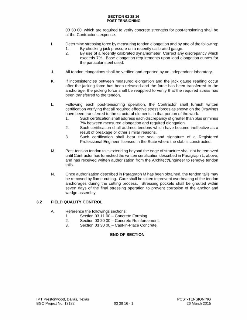
SECTION 03 38 16 POST-TENSIONING
IMT Prestonwood, Dallas, Texas POST-TENSIONING BGO Project No. 13182 03 38 16 - 1 26 March 2015
03 30 00, which are required to verify concrete strengths for post-tensioning shall be at the Contractor’s expense.
I. Determine stressing force by measuring tendon elongation and by one of the following:
1. By checking jack pressure on a recently calibrated gauge. 2. By use of a recently calibrated dynamometer. Correct any discrepancy which
exceeds 7%. Base elongation requirements upon load-elongation curves for the particular steel used.
J. All tendon elongations shall be verified and reported by an independent laboratory.
K. If inconsistencies between measured elongation and the jack gauge reading occur
after the jacking force has been released and the force has been transferred to the anchorage, the jacking force shall be reapplied to verify that the required stress has been transferred to the tendon.
L. Following each post-tensioning operation, the Contractor shall furnish written
certification verifying that all required effective stress forces as shown on the Drawings have been transferred to the structural elements in that portion of the work. 1. Such certification shall address each discrepancy of greater than plus or minus
7% between measured elongation and required elongation. 2. Such certification shall address tendons which have become ineffective as a
result of breakage or other similar reasons. 3. Such certification shall bear the seal and signature of a Registered
Professional Engineer licensed in the State where the slab is constructed.
M. Post-tension tendon tails extending beyond the edge of structure shall not be removed until Contractor has furnished the written certification described in Paragraph L, above, and has received written authorization from the Architect/Engineer to remove tendon tails.
N. Once authorization described in Paragraph M has been obtained, the tendon tails may
be removed by flame-cutting. Care shall be taken to prevent overheating of the tendon anchorages during the cutting process. Stressing pockets shall be grouted within seven days of the final stressing operation to prevent corrosion of the anchor and wedge assembly.
3.2 FIELD QUALITY CONTROL
A. Reference the followings sections: 1. Section 03 11 00 – Concrete Forming. 2. Section 03 20 00 – Concrete Reinforcement. 3. Section 03 30 00 – Cast-in-Place Concrete.
END OF SECTION
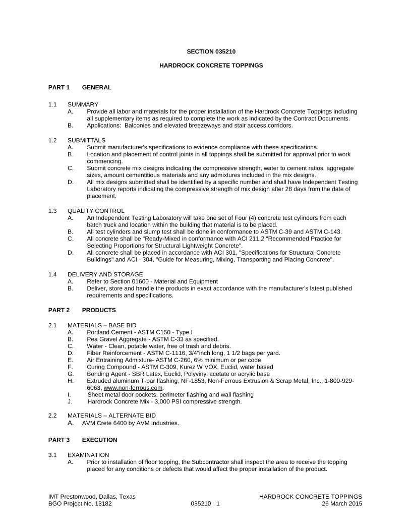
SECTION 035210
HARDROCK CONCRETE TOPPINGS
PART 1 GENERAL
1.1 SUMMARY A. Provide all labor and materials for the proper installation of the Hardrock Concrete Toppings including
all supplementary items as required to complete the work as indicated by the Contract Documents. B. Applications: Balconies and elevated breezeways and stair access corridors.
1.2 SUBMITTALS A. Submit manufacturer's specifications to evidence compliance with these specifications. B. Location and placement of control joints in all toppings shall be submitted for approval prior to work
commencing. C. Submit concrete mix designs indicating the compressive strength, water to cement ratios, aggregate
sizes, amount cementitious materials and any admixtures included in the mix designs. D. All mix designs submitted shall be identified by a specific number and shall have Independent Testing
Laboratory reports indicating the compressive strength of mix design after 28 days from the date of placement.
1.3 QUALITY CONTROL A. An Independent Testing Laboratory will take one set of Four (4) concrete test cylinders from each
batch truck and location within the building that material is to be placed. B. All test cylinders and slump test shall be done in conformance to ASTM C-39 and ASTM C-143. C. All concrete shall be "Ready-Mixed in conformance with ACI 211.2 "Recommended Practice for
Selecting Proportions for Structural Lightweight Concrete". D. All concrete shall be placed in accordance with ACI 301, "Specifications for Structural Concrete
Buildings" and ACI - 304, "Guide for Measuring, Mixing, Transporting and Placing Concrete".
1.4 DELIVERY AND STORAGE A. Refer to Section 01600 - Material and Equipment B. Deliver, store and handle the products in exact accordance with the manufacturer's latest published
requirements and specifications.
PART 2 PRODUCTS
2.1 MATERIALS – BASE BID A. Portland Cement - ASTM C150 - Type I B. Pea Gravel Aggregate - ASTM C-33 as specified. C. Water - Clean, potable water, free of trash and debris. D. Fiber Reinforcement - ASTM C-1116, 3/4"inch long, 1 1/2 bags per yard. E. Air Entraining Admixture- ASTM C-260, 6% minimum or per code F. Curing Compound - ASTM C-309, Kurez W VOX, Euclid, water based G. Bonding Agent - SBR Latex, Euclid, Polyvinyl acetate or acrylic base H. Extruded aluminum T-bar flashing, NF-1853, Non-Ferrous Extrusion & Scrap Metal, Inc., 1-800-929-
6063, www.non-ferrous.com. I. Sheet metal door pockets, perimeter flashing and wall flashing J. Hardrock Concrete Mix - 3,000 PSI compressive strength.
2.2 MATERIALS – ALTERNATE BID
A. AVM Crete 6400 by AVM Industries.
PART 3 EXECUTION
3.1 EXAMINATION A. Prior to installation of floor topping, the Subcontractor shall inspect the area to receive the topping
placed for any conditions or defects that would affect the proper installation of the product.
IMT Prestonwood, Dallas, Texas HARDROCK CONCRETE TOPPINGS BGO Project No. 13182 035210 - 1 26 March 2015
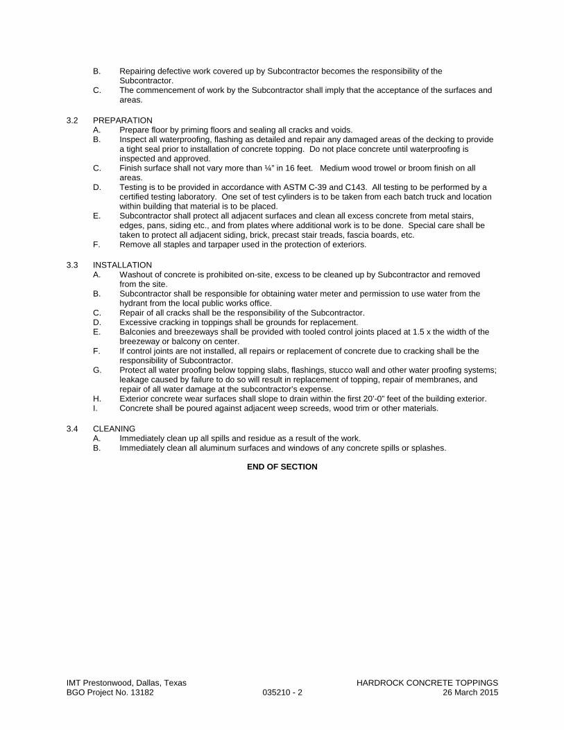
B. Repairing defective work covered up by Subcontractor becomes the responsibility of the Subcontractor.
C. The commencement of work by the Subcontractor shall imply that the acceptance of the surfaces and areas.
3.2 PREPARATION A. Prepare floor by priming floors and sealing all cracks and voids. B. Inspect all waterproofing, flashing as detailed and repair any damaged areas of the decking to provide
a tight seal prior to installation of concrete topping. Do not place concrete until waterproofing is inspected and approved.
C. Finish surface shall not vary more than ¼” in 16 feet. Medium wood trowel or broom finish on all areas.
D. Testing is to be provided in accordance with ASTM C-39 and C143. All testing to be performed by a certified testing laboratory. One set of test cylinders is to be taken from each batch truck and location within building that material is to be placed.
E. Subcontractor shall protect all adjacent surfaces and clean all excess concrete from metal stairs, edges, pans, siding etc., and from plates where additional work is to be done. Special care shall be taken to protect all adjacent siding, brick, precast stair treads, fascia boards, etc.
F. Remove all staples and tarpaper used in the protection of exteriors.
3.3 INSTALLATION A. Washout of concrete is prohibited on-site, excess to be cleaned up by Subcontractor and removed
from the site. B. Subcontractor shall be responsible for obtaining water meter and permission to use water from the
hydrant from the local public works office. C. Repair of all cracks shall be the responsibility of the Subcontractor. D. Excessive cracking in toppings shall be grounds for replacement. E. Balconies and breezeways shall be provided with tooled control joints placed at 1.5 x the width of the
breezeway or balcony on center. F. If control joints are not installed, all repairs or replacement of concrete due to cracking shall be the
responsibility of Subcontractor. G. Protect all water proofing below topping slabs, flashings, stucco wall and other water proofing systems;
leakage caused by failure to do so will result in replacement of topping, repair of membranes, and repair of all water damage at the subcontractor’s expense.
H. Exterior concrete wear surfaces shall slope to drain within the first 20’-0” feet of the building exterior. I. Concrete shall be poured against adjacent weep screeds, wood trim or other materials.
3.4 CLEANING A. Immediately clean up all spills and residue as a result of the work. B. Immediately clean all aluminum surfaces and windows of any concrete spills or splashes.
END OF SECTION
IMT Prestonwood, Dallas, Texas HARDROCK CONCRETE TOPPINGS BGO Project No. 13182 035210 - 2 26 March 2015
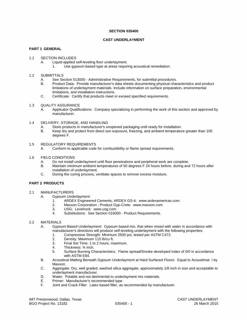
IMT Prestonwood, Dallas, Texas CAST UNDERLAYMENT BGO Project No. 13182 035400 - 1 26 March 2015
SECTION 035400
CAST UNDERLAYMENT
PART 1 GENERAL
1.1 SECTION INCLUDES A. Liquid-applied self-leveling floor underlayment.
1. Use gypsum-based type at areas requiring acoustical remediation.
1.2 SUBMITTALS A. See Section 013000 - Administrative Requirements, for submittal procedures. B. Product Data: Provide manufacturer's data sheets documenting physical characteristics and product
limitations of underlayment materials. Include information on surface preparation, environmental limitations, and installation instructions.
C. Certificate: Certify that products meet or exceed specified requirements.
1.3 QUALITY ASSURANCE A. Applicator Qualifications: Company specializing in performing the work of this section and approved by
manufacturer.
1.4 DELIVERY, STORAGE, AND HANDLING A. Store products in manufacturer's unopened packaging until ready for installation. B. Keep dry and protect from direct sun exposure, freezing, and ambient temperature greater than 105
degrees F.
1.5 REGULATORY REQUIREMENTS A. Conform to applicable code for combustibility or flame spread requirements.
1.6 FIELD CONDITIONS A. Do not install underlayment until floor penetrations and peripheral work are complete. B. Maintain minimum ambient temperatures of 50 degrees F 24 hours before, during and 72 hours after
installation of underlayment. C. During the curing process, ventilate spaces to remove excess moisture.
PART 2 PRODUCTS
2.1 MANUFACTURERS A. Gypsum Underlayment:
1. ARDEX Engineered Cements; ARDEX GS-4: www.ardexamericas.com. 2. Maxxon Corporation ; Product Gyp-Crete: www.maxxon.com 3. USG; Levelrock: www.usg.com. 4. Substitutions: See Section 016000 - Product Requirements.
2.2 MATERIALS A. Gypsum-Based Underlayment: Gypsum based mix, that when mixed with water in accordance with
manufacturer's directions will produce self-leveling underlayment with the following properties: 1. Compressive Strength: Minimum 2500 psi, tested per ASTM C472. 2. Density: Maximum 115 lb/cu ft. 3. Final Set Time: 1 to 2 hours, maximum. 4. Thickness: ¾ inch. 5. Surface Burning Characteristics: Flame spread/Smoke developed index of 0/0 in accordance
with ASTM E84. B. Acoustical Matting Beneath Gypsum Underlayment at Hard Surfaced Floors: Equal to Acoustimat I by
Maxxon. C. Aggregate: Dry, well graded, washed silica aggregate, approximately 1/8 inch in size and acceptable to
underlayment manufacturer. D. Water: Potable and not detrimental to underlayment mix materials. E. Primer: Manufacturer's recommended type. F. Joint and Crack Filler: Latex based filler, as recommended by manufacturer.
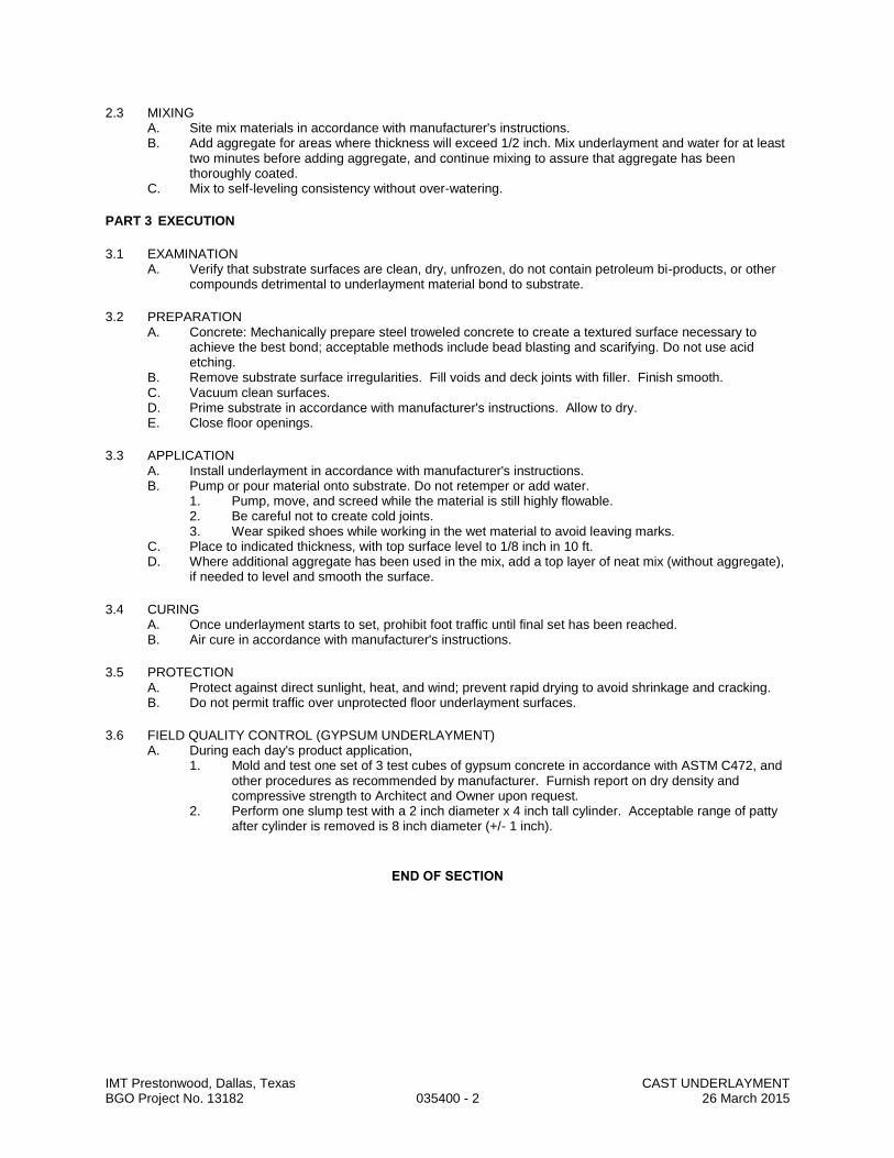
IMT Prestonwood, Dallas, Texas CAST UNDERLAYMENT BGO Project No. 13182 035400 - 2 26 March 2015
2.3 MIXING A. Site mix materials in accordance with manufacturer's instructions. B. Add aggregate for areas where thickness will exceed 1/2 inch. Mix underlayment and water for at least
two minutes before adding aggregate, and continue mixing to assure that aggregate has been thoroughly coated.
C. Mix to self-leveling consistency without over-watering.
PART 3 EXECUTION
3.1 EXAMINATION A. Verify that substrate surfaces are clean, dry, unfrozen, do not contain petroleum bi-products, or other
compounds detrimental to underlayment material bond to substrate.
3.2 PREPARATION A. Concrete: Mechanically prepare steel troweled concrete to create a textured surface necessary to
achieve the best bond; acceptable methods include bead blasting and scarifying. Do not use acid etching.
B. Remove substrate surface irregularities. Fill voids and deck joints with filler. Finish smooth. C. Vacuum clean surfaces. D. Prime substrate in accordance with manufacturer's instructions. Allow to dry. E. Close floor openings.
3.3 APPLICATION A. Install underlayment in accordance with manufacturer's instructions. B. Pump or pour material onto substrate. Do not retemper or add water.
1. Pump, move, and screed while the material is still highly flowable. 2. Be careful not to create cold joints. 3. Wear spiked shoes while working in the wet material to avoid leaving marks.
C. Place to indicated thickness, with top surface level to 1/8 inch in 10 ft. D. Where additional aggregate has been used in the mix, add a top layer of neat mix (without aggregate),
if needed to level and smooth the surface.
3.4 CURING A. Once underlayment starts to set, prohibit foot traffic until final set has been reached. B. Air cure in accordance with manufacturer's instructions.
3.5 PROTECTION A. Protect against direct sunlight, heat, and wind; prevent rapid drying to avoid shrinkage and cracking. B. Do not permit traffic over unprotected floor underlayment surfaces.
3.6 FIELD QUALITY CONTROL (GYPSUM UNDERLAYMENT) A. During each day's product application,
1. Mold and test one set of 3 test cubes of gypsum concrete in accordance with ASTM C472, and other procedures as recommended by manufacturer. Furnish report on dry density and compressive strength to Architect and Owner upon request.
2. Perform one slump test with a 2 inch diameter x 4 inch tall cylinder. Acceptable range of patty after cylinder is removed is 8 inch diameter (+/- 1 inch).
END OF SECTION

IMT Prestonwood, Dallas, Texas UNIT MASONRY BGO Project No. 13182 042000 - 1 26 March 2015
SECTION 042000
UNIT MASONRY
PART 1 GENERAL
1.1 SECTION INCLUDES A. Concrete Block. B. Clay Facing Brick. C. Mortar and Grout. D. Reinforcement and Anchorage. E. Flashings. F. Lintels. G. Accessories.
1.2 ADMINISTRATIVE REQUIREMENTS A. Preinstallation Meeting: Convene a preinstallation meeting one week before starting work of this
section; require attendance by all relevant installers.
1.3 SUBMITTALS A. See Section 013000 - Administrative Requirements, for submittal procedures. B. Product Data: Provide data for masonry units, fabricated wire reinforcement, mortar, and masonry
accessories. C. Samples: Submit four samples of decorative block units to illustrate color, texture, and extremes of
color range. D. Manufacturer's Certificate: Certify that masonry units meet or exceed specified requirements. E. Manufacturer's Certificate: Certify that water repellent admixture manufacturer has certified masonry
unit manufacturer as an approved user of water repellent admixture in the manufacture of concrete block.
F. Test Reports: Concrete masonry manufacturer's test reports for units with integral water repellent admixture.
1.4 QUALITY ASSURANCE A. Comply with provisions of ACI 530/530.1/ERTA, except where exceeded by requirements of the
contract documents.
1.5 MOCK-UP A. Construct a masonry wall as a mock-up panel sized 8 feet long by 6 feet high; include mortar and
accessories and structural backup in mock-up. B. Locate where directed. C. Mock-up may remain as part of the Work.
1.6 DELIVERY, STORAGE, AND HANDLING A. Deliver, handle, and store masonry units by means that will prevent mechanical damage and
contamination by other materials.

IMT Prestonwood, Dallas, Texas UNIT MASONRY BGO Project No. 13182 042000 - 2 26 March 2015
PART 2 PRODUCTS
2.1 CONCRETE MASONRY UNITS A. Concrete Block: Comply with referenced standards and as follows:
1. Size: Standard units with nominal face dimensions of 16 x 8 inches and nominal depths as indicated on the drawings for specific locations.
2. Special Shapes: Provide non-standard blocks configured for corners. 3. Non-Loadbearing Units: ASTM C129.
a. Hollow block , as indicated. b. Lightweight.
B. Fire Rated CMU: 1. Provide block complying with UL requirements for ratings indicated with UL classification
marking. 2. Provide units having material composition and cross-sectional areas as required to meet
building code requirements for hourly fire-resistive wall ratings as indicated on the Drawings. C. Decorative Units:
1. ASTM C 90, Type I; light weight; minimum 3000 psi net compressive strength. 2. Aggregate: Meet requirements of ASTM C 331. 3. Provide with integral water repellant equal to WR Grace Dry-Block 4. Texture and Color: Refer to Finish Legend.
2.2 BRICK UNITS A. Manufacturers:
1. Acme Brick Company: www.brick.com. 2. Boral Bricks, Inc : www.boralbricks.com. 3. Substitutions: See section 016000 - Product requirements.
B. Facing Brick: ASTM C216, Type FBS, Grade SW. 1. Color and texture to match Architect's sample. 2. Nominal size: As indicated on drawings. 3. Special shapes: Molded units as required by conditions indicated, unless standard units can be
sawn to produce equivalent effect. 4. Compressive strength: As indicated on drawings, measured in accordance with ASTM C67.
2.3 MORTAR AND GROUT MATERIALS A. Masonry Cement: ASTM C91, Type N.
1. Colored mortar: Premixed cement as required to match Architect's color sample. B. Mortar Aggregate: ASTM C144. C. Grout Aggregate: ASTM C404. D. Water: Clean and potable. E. Accelerating Admixture: Nonchloride type for use in cold weather. F. Integral Water Repellent Admixture for Mortar and Grout (for use at decorative cmu exposed to the
elements): Polymeric liquid admixture added to mortar and grout at the time of manufacture. 1. Performance of Mortar and Grout with Integral Water Repellent:
a. Water Permeance: When tested per ASTM E514 for a minimum of 72 hours. 1) No water visible on back of wall above flashing at the end of 24 hours. 2) No flow of water from flashing equal to or greater than 0.032 gallons per hour at
the end of 24 hours. 3) No more than 25% of wall area above flashing visibly damp at end of test.
b. Flexural Bond Strength: ASTM C1357; minimum 10% increase. c. Compressive Strength: ASTM C1314; maximum 5% decrease. d. Drying Shrinkage: ASTM C1148; maximum 5% increase in shrinkage.
2. Use only in combination with masonry units produced with integral water repellent admixture.

IMT Prestonwood, Dallas, Texas UNIT MASONRY BGO Project No. 13182 042000 - 3 26 March 2015
2.4 REINFORCEMENT AND ANCHORAGE A. Manufacturers of Joint Reinforcement and Anchors:
1. Blok-Lok Limited : www.blok-lok.com. 2. Hohmann & Barnard, Inc (including Dur-O-Wal brand) : www.h-b.com. 3. WIRE-BOND: www.wirebond.com. 4. Substitutions: See Section 016000 - Product Requirements.
B. Reinforcing Steel: ASTM A615/A615M Grade 40 (280) deformed billet bars; galvanized. C. Joint Reinforcement: Use ladder type joint reinforcement where vertical reinforcement is involved and
truss type elsewhere, unless otherwise indicated. D. Single Wythe Joint Reinforcement: Truss or ladder type; stainless steel conforming to ASTM
A580/A580M Type 304; 0.1483 inch side rods with 0.1483 inch cross rods; width as required to provide not more than 1 inch and not less than 1/2 inch of mortar coverage on each exposure.
E. Multiple Wythe Joint Reinforcement: Truss type; fabricated with moisture drip; ASTM A 82/A 82M steel wire, hot dip galvanized after fabrication to ASTM A 153/153M, Class B; 0.1483 inch side rods with 0.1483 inch cross rods; width as required to provide not more than 1 inch and not less than 1/2 inch of mortar coverage on each exposure.
F. Masonry Veneer Anchors (for masonry over 3 stories in height): 2-piece anchors that permit differential movement between masonry veneer and structural backup, hot dip galvanized to ASTM A 153/A 153M, Class B. 1. Anchor plates: Not less than 0.075 inch thick, designed for fastening to structural backup
through sheathing by two fasteners ; provide design with legs that penetrate sheathing and insulation to provide positive anchorage.
2. Wire ties: Manufacturer's standard shape, 0.1875 inch thick. 3. Vertical adjustment: Not less than 3-1/2 inches.
G. Masonry Veneer Anchors (for masonry 3 stories in height or less): 1. Model No. AA311, 7/8" wide x 7" long minimum (masonry ledge depth plus 4"), corrugated
sheet steel, 20 gage, galvanized finish, as made by AA Wire Products or comparable product by Dur-O- Wall Inc., or Heckman
2.5 FLASHINGS A. Rubberized-Asphalt Flashing: Composite flashing product consisting of a pliable, adhesive rubberized-
asphalt compound, bonded to a high-density, cross-laminated polyethylene film to produce an overall thickness of not less than 0.040 inch. 1. Products: Subject to compliance with requirements, provide one of the following:
a. Carlisle Coatings & Waterproofing; CCW-705-TWF Thru-Wall Flashing. b. Grace Construction Products, W. R. Grace & Co. - Conn.; Perm-A-Barrier Wall Flashing. c. Hohmann & Barnard, Inc.; Textroflash.
B. Lap Sealant: Butyl type as specified in Section 079005.
2.6 ACCESSORIES A. Preformed Control Joints: Rubber material. Provide with corner and tee accessories, fused joints.
1. Manufacturers: a. Blok-Lok Limited : www.blok-lok.com. b. Hohmann & Barnard, Inc (including Dur-O-Wal brand) : www.h-b.com. c. WIRE-BOND: www.wirebond.com. d. Substitutions: See Section 016000 - Product Requirements.
B. Cavity Mortar Control: Semi-rigid polyethylene or polyester mesh panels, sized to thickness of wall cavity, and designed to prevent mortar droppings from clogging weeps and cavity vents and allow proper cavity drainage. 1. Mortar Diverter: Panels designed for installation at flashing locations.
a. Manufacturers: 1) Mortar Net USA, Ltd ; Mortar Net with Insect Barrier: www.mortarnet.com. 2) Substitutions: See Section 016000 - Product Requirements.
C. Nailing Strips: Softwood lumber, preservative treated; as specified in Section 061000. D. Weeps: Molded PVC grilles, insect resistant.
1. Manufacturers: a. Blok-Lok Limited : www.blok-lok.com. b. Hohmann & Barnard, Inc : www.h-b.com. c. WIRE-BOND : www.wirebond.com. d. Substitutions: See Section 016000 - Product Requirements.
E. Cleaning Solution: Non-acidic, not harmful to masonry work or adjacent materials.

IMT Prestonwood, Dallas, Texas UNIT MASONRY BGO Project No. 13182 042000 - 4 26 March 2015
2.7 LINTELS A. Concrete Lintels: ASTM C 1623, matching CMUs in color, texture, and density classification; and with
reinforcing bars indicated. Provide lintels with net-area compressive strength not less than CMUs.
2.8 MORTAR AND GROUT MIXES A. Mortar for Unit Masonry: ASTM C270, using the Proportion Specification.
1. Masonry below grade and in contact with earth: Type S. 2. Exterior, non-loadbearing masonry: Type N. 3. Interior, non-loadbearing masonry: Type O.
B. Colored Mortar: Proportion selected pigments and other ingredients to match Architect's sample, without exceeding manufacturer's recommended pigment-to-cement ratio.
C. Grout: ASTM C476. Consistency required to fill completely volumes indicated for grouting; fine grout for spaces with smallest horizontal dimension of 2 inches or less; coarse grout for spaces with smallest horizontal dimension greater than 2 inches.
D. Admixtures: Add to mixture at manufacturer's recommended rate and in accordance with manufacturer's instructions; mix uniformly.
E. Mixing: Use mechanical batch mixer and comply with referenced standards.
PART 3 EXECUTION
3.1 EXAMINATION A. Verify that field conditions are acceptable and are ready to receive masonry. B. Verify that related items provided under other sections are properly sized and located. C. Verify that built-in items are in proper location, and ready for roughing into masonry work.
3.2 PREPARATION A. Direct and coordinate placement of metal anchors supplied for installation under other sections. B. Provide temporary bracing during installation of masonry work. Maintain in place until building
structure provides permanent bracing.
3.3 COLD AND HOT WEATHER REQUIREMENTS A. Comply with requirements of ACI 530/530.1/ERTA or applicable building code, whichever is more
stringent.
3.4 COURSING A. Establish lines, levels, and coursing indicated. Protect from displacement. B. Maintain masonry courses to uniform dimension. Form vertical and horizontal joints of uniform
thickness. C. Concrete Masonry Units:
1. Bond: Running. D. Brick Units: E. Calcium Silicate Units:
1. Bond: As indicated.
3.5 PLACING AND BONDING A. Lay solid masonry units in full bed of mortar, with full head joints, uniformly jointed with other work. B. Lay hollow masonry units with face shell bedding on head and bed joints. C. Buttering corners of joints or excessive furrowing of mortar joints is not permitted. D. Remove excess mortar and mortar smears as work progresses. E. Remove excess mortar with water repellent admixture promptly. Do not use acids, sandblasting or
high pressure cleaning methods. F. Interlock intersections and external corners , except for units laid in stack bond. G. Do not shift or tap masonry units after mortar has achieved initial set. Where adjustment must be
made, remove mortar and replace. H. Perform job site cutting of masonry units with proper tools to provide straight, clean, unchipped edges.
Prevent broken masonry unit corners or edges. I. Cut mortar joints flush where wall tile is scheduled or resilient base is scheduled. J. Isolate masonry partitions from vertical structural framing members with a control joint as indicated. K. Isolate top joint of masonry partitions from horizontal structural framing members and slabs or decks
with compressible joint filler.
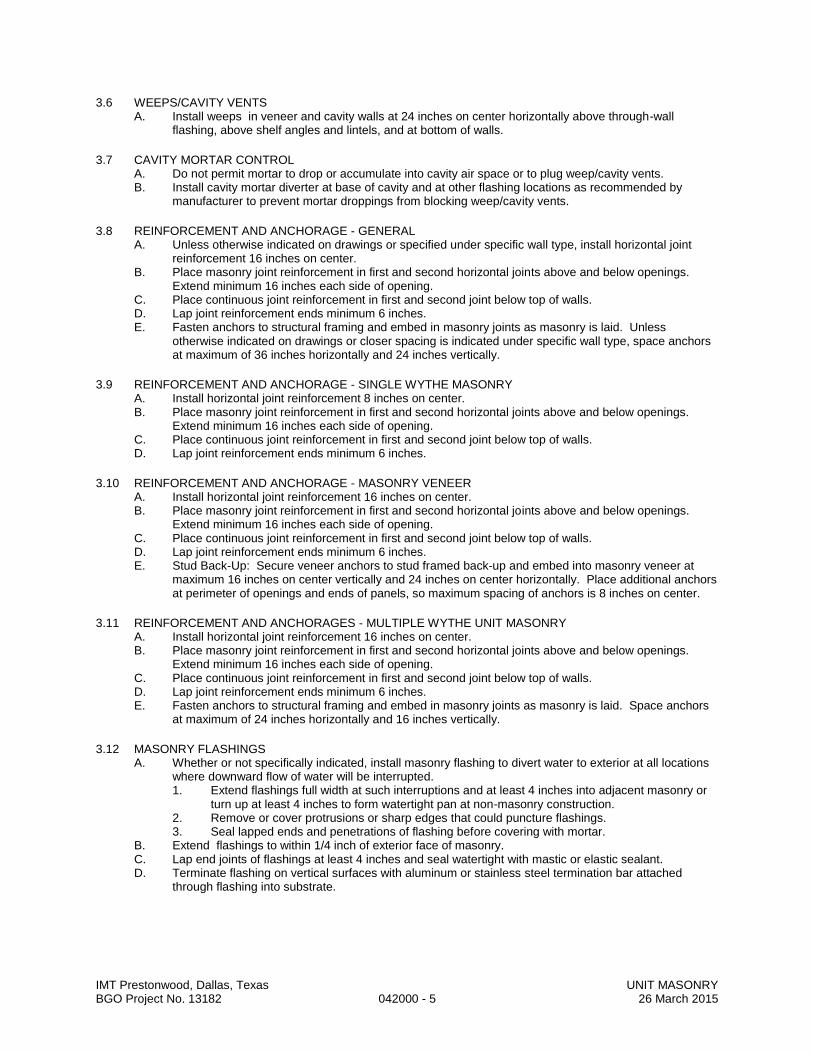
IMT Prestonwood, Dallas, Texas UNIT MASONRY BGO Project No. 13182 042000 - 5 26 March 2015
3.6 WEEPS/CAVITY VENTS A. Install weeps in veneer and cavity walls at 24 inches on center horizontally above through-wall
flashing, above shelf angles and lintels, and at bottom of walls.
3.7 CAVITY MORTAR CONTROL A. Do not permit mortar to drop or accumulate into cavity air space or to plug weep/cavity vents. B. Install cavity mortar diverter at base of cavity and at other flashing locations as recommended by
manufacturer to prevent mortar droppings from blocking weep/cavity vents.
3.8 REINFORCEMENT AND ANCHORAGE - GENERAL A. Unless otherwise indicated on drawings or specified under specific wall type, install horizontal joint
reinforcement 16 inches on center. B. Place masonry joint reinforcement in first and second horizontal joints above and below openings.
Extend minimum 16 inches each side of opening. C. Place continuous joint reinforcement in first and second joint below top of walls. D. Lap joint reinforcement ends minimum 6 inches. E. Fasten anchors to structural framing and embed in masonry joints as masonry is laid. Unless
otherwise indicated on drawings or closer spacing is indicated under specific wall type, space anchors at maximum of 36 inches horizontally and 24 inches vertically.
3.9 REINFORCEMENT AND ANCHORAGE - SINGLE WYTHE MASONRY A. Install horizontal joint reinforcement 8 inches on center. B. Place masonry joint reinforcement in first and second horizontal joints above and below openings.
Extend minimum 16 inches each side of opening. C. Place continuous joint reinforcement in first and second joint below top of walls. D. Lap joint reinforcement ends minimum 6 inches.
3.10 REINFORCEMENT AND ANCHORAGE - MASONRY VENEER A. Install horizontal joint reinforcement 16 inches on center. B. Place masonry joint reinforcement in first and second horizontal joints above and below openings.
Extend minimum 16 inches each side of opening. C. Place continuous joint reinforcement in first and second joint below top of walls. D. Lap joint reinforcement ends minimum 6 inches. E. Stud Back-Up: Secure veneer anchors to stud framed back-up and embed into masonry veneer at
maximum 16 inches on center vertically and 24 inches on center horizontally. Place additional anchors at perimeter of openings and ends of panels, so maximum spacing of anchors is 8 inches on center.
3.11 REINFORCEMENT AND ANCHORAGES - MULTIPLE WYTHE UNIT MASONRY A. Install horizontal joint reinforcement 16 inches on center. B. Place masonry joint reinforcement in first and second horizontal joints above and below openings.
Extend minimum 16 inches each side of opening. C. Place continuous joint reinforcement in first and second joint below top of walls. D. Lap joint reinforcement ends minimum 6 inches. E. Fasten anchors to structural framing and embed in masonry joints as masonry is laid. Space anchors
at maximum of 24 inches horizontally and 16 inches vertically.
3.12 MASONRY FLASHINGS A. Whether or not specifically indicated, install masonry flashing to divert water to exterior at all locations
where downward flow of water will be interrupted. 1. Extend flashings full width at such interruptions and at least 4 inches into adjacent masonry or
turn up at least 4 inches to form watertight pan at non-masonry construction. 2. Remove or cover protrusions or sharp edges that could puncture flashings. 3. Seal lapped ends and penetrations of flashing before covering with mortar.
B. Extend flashings to within 1/4 inch of exterior face of masonry. C. Lap end joints of flashings at least 4 inches and seal watertight with mastic or elastic sealant. D. Terminate flashing on vertical surfaces with aluminum or stainless steel termination bar attached
through flashing into substrate.

IMT Prestonwood, Dallas, Texas UNIT MASONRY BGO Project No. 13182 042000 - 6 26 March 2015
3.13 LINTELS A. Install loose steel lintels over openings. B. Install reinforced unit masonry lintels over openings where steel or precast concrete lintels are not
scheduled.
3.14 GROUTED COMPONENTS A. Lap splices minimum 24 bar diameters. B. Support and secure reinforcing bars from displacement. Maintain position within 1/2 inch of
dimensioned position. C. Place and consolidate grout fill without displacing reinforcing. D. At bearing locations, fill masonry cores with grout for a minimum 12 inches either side of opening.
3.15 ENGINEERED MASONRY A. Lay masonry units with core cells vertically aligned clear of mortar and unobstructed. B. Place mortar in masonry unit bed joints back 1/4 inch from edge of unit grout spaces, bevel back and
upward. Permit mortar to cure 7 days before placing grout. C. Reinforce masonry unit cores with reinforcement bars and grout. D. Retain vertical reinforcement in position at top and bottom of cells and at intervals not exceeding 192
bar diameters. Splice reinforcement in accordance with Section 03200. E. Grout spaces less than 2 inches in width with fine grout using low lift grouting techniques. Grout
spaces 2 inches or greater in width with course grout using high or low lift grouting techniques. F. When grouting is stopped for more than 1 hour, terminate grout 1-1/2 inch below top of upper masonry
unit to form a positive key for subsequent grout placement. G. Low Lift Grouting: Place first lift of grout to a height of 16 inches and rod for grout consolidation. Place
subsequent lifts in 8 inch increments and rod for grout consolidation. H. High Lift Grouting
1. Provide cleanout opening no less than 4 inches high at the bottom of each cell to be grouted by cutting one face shell of masonry unit.
2. In double wythe walls, omit every second masonry unit in one of the wythes for clean out and cell inspection purposes.
3. In double wythe walls, construct vertical grout barriers or dams between the masonry wythes, with masonry units every 30 feet maximum.
4. Clean out masonry cells [and cavities] with high pressure water spray. Permit complete water drainage.
5. Request the Owner’s Representative to inspect the cells Allow 3 days advance notice of inspection.
6. After cleaning and cell inspection, seal openings with masonry units. 7. Pump grout into spaces. Maintain water content in grout to intended slump without aggregate
segregation. 8. Limit grout lift to 48 inches and rod for grout consolidation. Wait 30 to 60 minutes before
placing next lift.
3.16 CONTROL AND EXPANSION JOINTS A. Do not continue horizontal joint reinforcement through control and expansion joints. B. Form control joint with a sheet building paper bond breaker fitted to one side of the hollow contour end
of the block unit. Fill the resultant core with grout fill. Rake joint at exposed unit faces for placement of backer rod and sealant.
C. Install preformed control joint device in continuous lengths. Seal butt and corner joints in accordance with manufacturer's instructions.
D. Size control joint in accordance with Section 079005 for sealant performance. E. Form expansion joint as detailed.
3.17 TOLERANCES A. Maximum Variation from Alignment of Columns: 1/4 inch. B. Maximum Variation From Unit to Adjacent Unit: 1/16 inch. C. Maximum Variation from Plane of Wall: 1/4 inch in 10 ft and 1/2 inch in 20 ft or more. D. Maximum Variation from Plumb: 1/4 inch per story non-cumulative; 1/2 inch in two stories or more. E. Maximum Variation from Level Coursing: 1/8 inch in 3 ft and 1/4 inch in 10 ft; 1/2 inch in 30 ft. F. Maximum Variation of Joint Thickness: 1/8 inch in 3 ft. G. Maximum Variation from Cross Sectional Thickness of Walls: 1/4 inch.
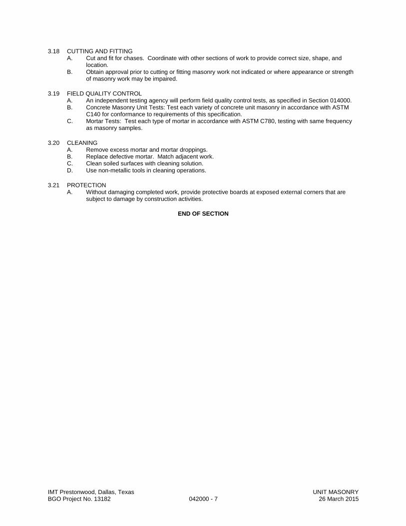
IMT Prestonwood, Dallas, Texas UNIT MASONRY BGO Project No. 13182 042000 - 7 26 March 2015
3.18 CUTTING AND FITTING A. Cut and fit for chases. Coordinate with other sections of work to provide correct size, shape, and
location. B. Obtain approval prior to cutting or fitting masonry work not indicated or where appearance or strength
of masonry work may be impaired.
3.19 FIELD QUALITY CONTROL A. An independent testing agency will perform field quality control tests, as specified in Section 014000. B. Concrete Masonry Unit Tests: Test each variety of concrete unit masonry in accordance with ASTM
C140 for conformance to requirements of this specification. C. Mortar Tests: Test each type of mortar in accordance with ASTM C780, testing with same frequency
as masonry samples.
3.20 CLEANING A. Remove excess mortar and mortar droppings. B. Replace defective mortar. Match adjacent work. C. Clean soiled surfaces with cleaning solution. D. Use non-metallic tools in cleaning operations.
3.21 PROTECTION A. Without damaging completed work, provide protective boards at exposed external corners that are
subject to damage by construction activities.
END OF SECTION

SECTION 04 22 00 CONCRETE MASONRY UNITS
IMT Prestonwood, Dallas, Texas CONCRETE MASONRY UNITS BGO Project No. 13182 04 22 00 - 1 26 March 2015
PART 1 GENERAL 1.1 SUMMARY
A. Section Includes: 1. Furnish all labor, materials, services and equipment as required in conjunction
with or properly incidental to construction of all concrete masonry units as described herein and/or as shown on the Drawings.
B. Related Documents:
1. Drawings and general provisions of Contract, including General and Supplementary Conditions and Division 1, General Requirements, apply to Work of this section.
C. Related Sections:
1. Section 03 20 00 – Concrete Reinforcement. 2. Section 05 50 00 – Metal Fabrications.
1.2 REFERENCES
A. Concrete masonry unit manufacturer shall certify that masonry units furnished meet or exceed requirements of this Specification.
B. The work in this Section, unless noted on the Drawings, or herein specified shall be
governed by the latest edition of the following codes or specifications. 1. ACI 531 – Building Code Requirements for Concrete Masonry Structures. 2. ASTM A 82 – Standard Specification for Steel Wire, Plain, for Concrete
Reinforcement. 3. ASTM C 145 – Standard Specifications for Solid Load Bearing Concrete
Masonry Units. 4. ASTM A 153 – Standard Specification for Zinc Coating (Hot-Dip) on Iron and
Steel Hardware. 5. ASTM A 615 – Standard Specification for Deformed and Plain Billet-Steel Bars
for Concrete Reinforcement. 6. ASTM C 90 – Standard Specification for Loadbearing Concrete Masonry
Units. 7. ASTM C 144 – Standard Specification for Aggregate for Masonry Mortar. 8. ASTM C 150 – Standard Specification for Portland Cement. 9. ASTM C 20 – Standard Specification for Hydrated Lime for Masonry
Purposes. 10. ASTM C 270 – Standard Specification for Mortar for Unit Masonry. 11. ASTM C 404 – Standard Specification for Aggregates for Masonry Grout. 12. ASTM C 476 – Standard Specification for Grout for Masonry. 13. International Masonry Industry All-Weather Council (MIAWC):
a. IMIAWC (CW) - Recommended Practices & Guide Specifications for Cold Weather Masonry Construction.
b. IMIAWC (HW) - Recommended Practices & Guide Specifications for Hot Weather Masonry Construction.
1.3 SUBMITTALS
A. Product Data: 1. Data for concrete masonry units, sizes, shapes and details. Include test data
indicating block conformance to specified ASTM specification. 2. Data for joint reinforcement. 3. Data for block admixture integral water repellent.
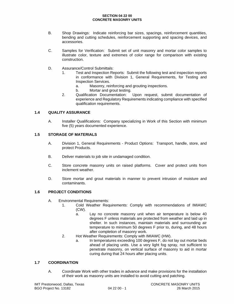
SECTION 04 22 00 CONCRETE MASONRY UNITS
IMT Prestonwood, Dallas, Texas CONCRETE MASONRY UNITS BGO Project No. 13182 04 22 00 - 1 26 March 2015
B. Shop Drawings: Indicate reinforcing bar sizes, spacings, reinforcement quantities,
bending and cutting schedules, reinforcement supporting and spacing devices, and accessories.
C. Samples for Verification: Submit set of unit masonry and mortar color samples to
illustrate color, texture and extremes of color range for comparison with existing construction.
D. Assurance/Control Submittals:
1. Test and Inspection Reports: Submit the following test and inspection reports in conformance with Division 1, General Requirements, for Testing and Inspection Services. a. Masonry, reinforcing and grouting inspections. b. Mortar and grout testing.
2. Qualification Documentation: Upon request, submit documentation of experience and Regulatory Requirements indicating compliance with specified qualification requirements.
1.4 QUALITY ASSURANCE
A. Installer Qualifications: Company specializing in Work of this Section with minimum five (5) years documented experience.
1.5 STORAGE OF MATERIALS
A. Division 1, General Requirements - Product Options: Transport, handle, store, and protect Products.
B. Deliver materials to job site in undamaged condition.
C. Store concrete masonry units on raised platforms. Cover and protect units from
inclement weather.
D. Store mortar and grout materials in manner to prevent intrusion of moisture and contaminants.
1.6 PROJECT CONDITIONS
A. Environmental Requirements: 1. Cold Weather Requirements: Comply with recommendations of IMIAWC
(CW). a. Lay no concrete masonry unit when air temperature is below 40
degrees F unless materials are protected from weather and laid up in shelter. In such instances, maintain materials and surrounding air temperature to minimum 50 degrees F prior to, during, and 48 hours after completion of masonry work.
2. Hot Weather Requirements: Comply with IMIAWC (HW). a. In temperatures exceeding 100 degrees F, do not lay out mortar beds
ahead of placing units. Use a very light fog spray, not sufficient to penetrate masonry, on vertical surface of masonry to aid in mortar curing during that 24 hours after placing units.
1.7 COORDINATION
A. Coordinate Work with other trades in advance and make provisions for the installation
of their work as masonry units are installed to avoid cutting and patching.
SECTION 04 22 00 CONCRETE MASONRY UNITS
IMT Prestonwood, Dallas, Texas CONCRETE MASONRY UNITS BGO Project No. 13182 04 22 00 - 1 26 March 2015
B. Coordinate masonry unit work with wall mounted lighting fixtures, plumbing items,
openings and chases for heating ducts, plumbing pipes, electrical conduit and mechanical louvers or vents. Build into Work as construction progresses.
C. Provide for installation of bolts, toggles, flashing, beams, anchors, hangers, attachment
strips, wall plugs and frames as required for support of structure and miscellaneous appliances.
PART 2 PRODUCTS 2.1 EXTERIOR WALL CONCRETE MASONRY UNITS
A. Concrete Block: ASTM C 90, Grade N, Type 1, light weight, load bearing, hollow block. 1. Integral block admixture water repellent added during block manufacture. 2. Integral color admixture pigment added during block manufacture to produce
a uniformly colored surface. 3. Size and Shape: Locations indicated on Drawings. a. 16 inches x 8 inches and nominal depth of 8 inches. b. 16 inches x 8 inches and nominal depth of 12 inches. 4. Exposed Face Texture: Selected by Architect. 5. Color: Selected by Architect. 6. Provide standard and fire rated units.
2.2 INTERIOR PARTITION CONCRETE MASONRY UNITS
A. Concrete Block: Comply with referenced standards and as follows: 1. Size: Standard units with nominal face dimensions indicated on Drawings. a. 16 x 8 inches and nominal depth of 8 inches.
b. Bullnose Units: Provide bullnose units at all interior corners, unless indicated otherwise on Drawings.
2. Load-Bearing Units: ASTM C 90, Grade N, Type 1, light weight. a. Hollow block. b. Exposed Faces: Manufacturer's standard grey color and texture.
3. Fire Rated Partitions: Units listed in UL FRD or permitted by Building Code. 2.3 MORTAR AND GROUT MATERIALS
A. Portland Cement: ASTM C 150, Type I; non-staining. Masonry cement not permitted.
1. Hydrated Lime: ASTM C 207, Type S. 2. Mortar Aggregate: ASTM C 144, free of clay or organic matter. 3. Grout Aggregate: ASTM C 404.
B. Water: Clean and potable.
C. Exterior Exposed Wall Mortar Color: Selected by Architect.
1. Integral mortar admixture water repellent added during mixing.
D. Interior Wall Mortar: Manufacturer’s standard grey color, U.N.O. by Architect.
2.4 REINFORCEMENT AND ANCHORAGE
A. Reinforcing Steel: ASTM A 615 Grade 60. 1. Deformed billet-steel bars. 2. Unfinished.

SECTION 04 22 00 CONCRETE MASONRY UNITS
IMT Prestonwood, Dallas, Texas CONCRETE MASONRY UNITS BGO Project No. 13182 04 22 00 - 1 26 March 2015
B. Single Wythe Joint Reinforcement - Truss type, ASTM A 82 steel wire, hot dipped galvanized after fabrication to ASTM A 153, Class B. 1. 9 gauge side rods and cross rods and diagonal ties, welded at 16" intervals to
continuous side rods forming truss design. 2. Prefabricated corner and “tee” intersecting units. 3. Width as required to provide not more than 1 inch and not less than 1/2 inch
of mortar coverage on each exposure. 4. Manufacturer:
a. Dur-O-Wall: www.dur-o-wall.com. b. Holman & Barnard: www.h-b.com. c. Masonry Reinforcing Corporation of America: www.wirebond.com. d. Southern Construction Products: www.scponline.com.
2.5 MORTAR AND GROUT MIXES
A. Mortar for Unit Masonry: ASTM C 270, using the Proportion Specification. 1. Type M: 2500 psi at 28 days or Type S: 1800 psi at 28 days; slump 9 inches
plus or minus 1 inch.
B. Grout: ASTM C 476, Portland cement, sand, pea gravel and water, 2000 psi at 28 days, slump 9 inches plus or minus 1 inch. Consistency required to fill completely volumes indicated for grouting; fine grout for spaces with smallest horizontal dimension of 2 inches or less; coarse grout for spaces with smallest horizontal dimension greater than 2 inches.
C. Mixing:
1. Mix mortar in accordance with ASTM C 270 in quantities needed for immediate use.
2. Mix grout in accordance with ASTM C 476 in quantities needed for immediate use.
3. Use mechanical batch mixer and comply with referenced standards. 4. Do not use anti-freeze compounds to lower the freezing point of mortar or
grout. 5. Mix integral water repellent admixture per manufacturer’s published
instructions. 6. Control batching procedure to ensure proper proportions by measuring
materials by volume. Measurement by shovel not permitted. PART 3 EXECUTION 3.1 EXAMINATION
A. Verify existing conditions to assure surfaces to support masonry are to proper grade, elevation, free from dirt or other deleterious matter and ready to receive Work.
B. Report in writing to Architect prevailing conditions that will adversely affect satisfactory
execution of the Work of this Section. Do not proceed with Work until unsatisfactory conditions have been corrected.
C. By beginning Work, Contractor accepts conditions and assumes responsibility for
correcting unsuitable conditions encountered at no additional cost to the Owner. 3.2 PREPARATION
A. Concrete Masonry Units: 1. Lay only dry units, free of paint, oil, efflorescence or foreign matter. 2. Remove laitance, loose aggregate or anything that prevents bonding to

SECTION 04 22 00 CONCRETE MASONRY UNITS
IMT Prestonwood, Dallas, Texas CONCRETE MASONRY UNITS BGO Project No. 13182 04 22 00 - 1 26 March 2015
surface.
B. Reinforcement: Before being placed, remove loose coatings from reinforcement.
C. Use masonry saws to cut masonry units. D. Provide temporary bracing during installation of masonry work. Maintain in place until
building structure provides permanent bracing. E. Direct and coordinate placement of metal anchors supplied for installation under other
sections. F. Verify holes and openings have been sealed to prevent escape of insulation.
3.3 INSTALLATION
A. Installation Tolerances: 1. Maximum Variation from Plumb:
a. Vertical lines and surfaces of columns and walls: 1) 1/4" in 10'-0". 2) 3/8" in 20'-0" maximum. 3) 1/2" maximum.
b. External corners or control joints: 1) 1/4" in 20'-0". 2) 1/2" in 40'-0" maximum.
2. Maximum Variation from Level or Grades for Exposed Lintels, Sill, Parapets or Horizontal Grooves: a. 1/4" on any bay or 20'-0". b. 1/2" in 40'-0".
3. Maximum Variation from Plan Location of Linear Building Line or Related Portions of Columns, Walls and Partitions: a. 1/2" in any bay or 20'-0". b. 3/4" in 40'-0".
4. Maximum Variation in Cross-Sectional Dimensions of Columns and Thickness of Walls: 1/4”.
B. Pattern Bond: Running bond with vertical joints located at centerline of masonry units
in alternate courses unless noted otherwise on architectural drawings.
C. General: 1. Set units plumb, true to lien and with level courses accurately spaced within
allowable tolerances. 2. Do not install cracked, broken or chipped masonry units exceeding ASTM
allowable. 3. Adjust masonry unit to final position while mortar is soft and plastic. 4. Where adjustment must be made or if units are displaced after mortar has
stiffened, remove units, clean joints and units of mortar and relay with fresh mortar.
5. Do not pound corners and jambs to fit stretcher units after they are set in position.
6. Adjust shelf angles to keep masonry level and at proper elevation. 7. Provide pressure relieving joints by placing continuous 1/8" foam pad under
shelf angle. 8. Interlock intersections and external corners.
D. Mortar and Grouting:
1. Place mortar in accordance with ASTM C 270.
SECTION 04 22 00 CONCRETE MASONRY UNITS
IMT Prestonwood, Dallas, Texas CONCRETE MASONRY UNITS BGO Project No. 13182 04 22 00 - 1 26 March 2015
a. Lay with full mortar coverage on horizontal and vertical face shells. b. Provide full mortar coverage on horizontal and vertical face shells and
webs where adjacent to cells of cavities to be filled with grout. 2. Place grout in accordance with ASTM C 476. 3. Provide protection for metal building frames and girts during placement of
mortar and grout. Do not permit mortar or grout in contact with metal building frames and girts.
4. High-Lift Grouting is not acceptable without prior written consent of the Engineer of Record.
5. Low-Lift Grouting is acceptable as follows: a. Limit height of pours to 60 inches.
b. For grout pours 12 inches high or less, the grout may be consolidated by rodding with a puddling stick.
c. For grout pours in excess of 12 inches, the grout shall be consolidated by means of a mechanical vibrator.
d. At intermediate levels, the top of the grout pour shall stop a minimum of 1 ½ inches below the top of the masonry units.
e. At the top of the wall, the grout shall be placed flush with the masonry units.
f. Pour grout only after vertical reinforcing is in place; place horizontal reinforcing as grout is poured. Prevent displacement of bars as grout is poured.
g. Place grout for each pour continuously and consolidate immediately; do not interrupt pours for more than 1 ½ hours.
6. Remove excess mortar from grout spaces.
E. Horizontal and Vertical Face Joints: 1. Construct uniform joints, 3/8" nominal thickness. 2. Shove vertical joints tight. 3. Tool concave joints in exposed surfaces when thumb-print hard with round
joints slightly larger than width of joint. 4. Flush cut all joints not exposed. 5. Fill horizontal joints between top of non-load bearing masonry partitions and
underside of beams or slabs with flexible material.
F. Control Joints: 1. Keep joints free of mortar by inserting continuous wood or metal temporary
strips. 2. Install where indicated and at following locations:
a. Changes in thickness, height and direction. b. Within 8'-0" of corners or offsets. c. At control or expansion joints in structure. d. At each side of openings greater than 24" wide. e. At foundation walls, shelf angles, setbacks and materials expanding
at different ratios. f. Space joints at 30'-0" o.c. maximum in uninterrupted walls. g. Provide continuous vertical control joints through bond beams except
at lintels above openings. h. Offset control joints to ends of lintels.
3. Install joint sealer as specified by Architect.
G. Collar Joints: 1. Keep cavity in cavity walls clean. 2. Remove all protruding mortar fins in cavity to be grouted.
H. Joining of Work:
1. When joining fresh masonry to set or partially set masonry construction,

SECTION 04 22 00 CONCRETE MASONRY UNITS
IMT Prestonwood, Dallas, Texas CONCRETE MASONRY UNITS BGO Project No. 13182 04 22 00 - 1 26 March 2015
remove loose units and mortar and clean exposed surface of set masonry prior to laying fresh masonry.
2. If necessary to stop off horizontal run of masonry, rack back one-half block length in each course.
3. Do not use toothing to join new masonry to set or partially set masonry.
I. Reinforcing and Ties: 1. Reinforcing Bars: Secure at locations indicated and to avoid displacement
during grouting. a. Maintain position within 1/2 inch of dimensioned position. b. Minimum spacing between bars or to masonry surfaces shall be one
bar diameter. 2. Horizontal joint reinforcing: Install horizontal joint reinforcement 16 inches on
center. a. Place masonry joint reinforcement in first and second horizontal joints
above and below openings. Extend minimum 16 inches each side of opening.
b. Place continuous joint reinforcement in first and second joint below top of walls.
c. Extend joint reinforcement entire length of bed joint. d. Lap reinforcement minimum 6" at ends. e. Bend or weld at offsets or special conditions.
J. Bond Beams:
1. Provide CMU bond beams at top of CMU walls and lintels above openings. 2. Reinforce bond beams with minimum of two bars and grout. Support and
secure reinforcing bars from displacement during grout fill. 3. Discontinue bond beams at expansion and control joints. 4. At bearing locations, fill masonry cores with grout for minimum 16 inches either
side of opening.
K. Flashing: 1. General:
a. Clean surface to receive flashing and remove projections which might puncture or damage flashing material.
b. Seal joints with manufacturer’s recommended adhesive. c. Seal top of flashing to ensure moisture cannot infiltrate behind
flashing. d. Continue flashing around corners. Ensure membrane material is not
interrupted in horizontal plane at corners. 2. Wall base, opening sills and heads:
a. Place flashing on mortar bed and cover with mortar. b. Start 1/2" from outside face of wall and turn up in cavity 8" minimum. c. Lap joints 4" minimum. d. Place flashing under and behind sills. e. Place flashing over steel lintels. f. Extend flashing beyond opening jamb lines.
L. Weep Holes: 1. Provide weep holes in head joints in first course immediately above flashing
by either leaving head joint free and clean of mortar or placing and leaving sash cord or plastic weeps in joint.
2. 24" o.c. maximum spacing. 3. Keep weep holes and area above flashing free of mortar waste.
M. Built-In Work:
1. As work progresses, install built-in metal door frames, window frames,
SECTION 04 22 00 CONCRETE MASONRY UNITS
IMT Prestonwood, Dallas, Texas CONCRETE MASONRY UNITS BGO Project No. 13182 04 22 00 - 1 26 March 2015
fabricated metal frames, mechanical louvers, plates and anchor bolts and other items to be built into the work and furnished under other sections.
2. Install built-in items plumb, level and true to line. 3. Where electric conduit, outlet, switch and other boxes occur, grind and cut
units before building-in services. Coordinate work with electrical installer. 4. Bed anchors of metal door frames in adjacent mortar joints. a. Fill frame voids solid with grout.
b. Fill adjacent masonry cores with grout minimum 12 inches for framed openings.
5. Do not build into masonry construction organic materials that are subject to deterioration. 6. Where recessed fire extinguisher cabinets, recessed drinking fountains, electric conduit, outlet, switch and other boxes occur, grind and cut units before building-in services. Coordinate with item installer.
3.4 CLEANING
A. Clean work. Remove efflorescence in accordance with manufacturer’s recommendations.
B. Remove excess mortar and mortar smears as work progresses. C. Replace defective mortar. Match adjacent work. D. Clean soiled surfaces with cleaning solution.
E. Leave area and surfaces clean and free of mortar spots, drippings and broken
masonry. 3.5 FIELD QUALITY CONTROL
A. Refer to Division 1, General Requirements, for additional requirements for a Contractor Quality Control Representative to perform contractor quality control inspections. 1. Inspect concrete masonry unit erection, color, texture, coursing, joints,
placement and type of reinforcing, reinforcing splicing, mortar and grout mixing, and grouting.
2. Document preparatory, initial and follow-up inspection in Contractor’s Test and Inspection Reports.
3. Test and Inspection Reports shall be available to Architect upon request.
B. Refer to Division 1, General Requirements, for Testing and Inspection Services: Perform the following inspections. 1. Perform the following inspections for conformance compliance with Contract
Documents. a. Start of Masonry Work:
1) Concrete unit masonry size, grade and type. 2) Proportions of site-prepared mortar. 3) Construction of mortar joints. 4) Location of reinforcement and connectors. 5) Specified size, grade and type of reinforcement. 6) Protection of masonry during cold weather or hot weather.
b. Before Grouting: 1) Verify that grout space is clean. 2) Placement of reinforcing and connectors. 3) Proportions of site-prepared grout. 4) Construction of mortar joints.
c. Grout placement and grouting procedures.
SECTION 04 22 00 CONCRETE MASONRY UNITS
IMT Prestonwood, Dallas, Texas CONCRETE MASONRY UNITS BGO Project No. 13182 04 22 00 - 1 26 March 2015
2. Perform the following tests: a. Mortar: Test and evaluate mortar in accordance with ASTM C 780.
1) Take 3 samples of mortar each day. b. Grout: Test and evaluate grout in accordance with ASTM C 1019.
1) Take 3 samples of grout each day. c. Prism: Test in accordance with ACI 530.1.
1) Perform 1 prism test for each 5,000 square feet of wall. 3. Reports: Prepare and submit test reports indicating results of tests made as
specified in Division 1, General Requirements, Quality Control.
C. Refer to Division 1, General Requirements - Testing and Inspection Services: Special Inspections. 1. Perform Special Inspections as required by the International Building Code
Section 1704 - Special Inspections, as indicated on Drawings and as required by the Building Official.
D. Correct deficiencies in products and installation found not to be in compliance with
Contract Documents. 3.6 PROTECTION OF FINISHED WORK
A. Protect finished Work.
B. Without damaging completed work, provide protective boards at external corners which may be damaged by construction activities.
END OF SECTION

SECTION 05 12 00 STRUCTURAL STEEL
IMT Prestonwood, Dallas, Texas STRUCTURAL STEEL BGO Project No. 13182 05 12 00 - 1 26 March 2015
PART 1 GENERAL 1.1 SUMMARY
A. Section Includes: 1. Furnish all labor, materials, services and equipment as required in conjunction
with or properly incidental to installation of structural steel as described herein and/or as shown on the Drawings.
B. Related Documents:
1. Drawings and general provisions of Contract, including General and Supplementary Conditions and Division 1, General Requirements, apply to the Work of this section.
C. Related Sections:
1. Section 05 21 00 – Steel Joist Framing. 2. Section 05 31 00 – Metal Deck. 3. Section 05 55 00 – Metal Fabrications.
1.2 REFERENCES
A. American Institute of Steel Construction (AISC): 1. AISC M016 – ASD Manual of Steel Construction. 2. AISC S303 – Code of Standard Practice for Steel Buildings and Bridges.
B. American Society for Testing and Materials (ASTM):
1. ASTM A 36 – Standard Specification for Carbon Structural Steel. 2. ASTM A 53 – Standard Specification for Pipe, Steel, Black and Hot-Dipped,
Zinc-Coated, Welded and Seamless. 3. ASTM A 325 – Standard Specification for Structural Bolts, Steel, Heat Treated,
120/105 ksi Minimum Tensile Strength. 4. ASTM A 108 – Standard Specification for Steel Bars, Carbon, Cold-Finished,
Standard Quality. 5. ASTM A 500 – Standard Specification for Cold-Formed Welded and Seamless
Carbon Steel Structural Tubing in Rounds and Shapes. 6. ASTM A 501 – Standard Specification for Hot-Formed Welded and Seamless
Carbon Steel Structural Tubing. 7. ASTM A 992/992M – Standard Specification for Steel for Structural Shapes for
Use in Building Framing. 8. ASTM C 1107 – Standard Specification for Packaged Dry, Hydraulic-Cement
Grout (Nonshrink). 9. ASTM E 164 – Standard Practice for Ultrasonic Contact Examination of
Weldments.
C. American Welding Society (AWS): 1. AWS A2.4 – Standard Symbols for Welding, Brazing, and Nondestructive
Examination. 2. AWS D1.1 – Structural Welding Code - Steel.
D. Steel Structures Painting Council (SSPC):
1. SSPC 1 – Solvent Cleaning. 2. SSPC 3 – Power Tool Cleaning. 3. SSPC-Paint 15 – Steel Joist Shop Primer; Society for Protective Coatings.
1.3 QUALITY ASSURANCE
SECTION 05 12 00 STRUCTURAL STEEL
IMT Prestonwood, Dallas, Texas STRUCTURAL STEEL BGO Project No. 13182 05 12 00 - 1 26 March 2015
A. Fabricate structural steel members in accordance with AISC M016. B. Erector Qualifications:
1. Company specializing in performing structural steel erection work with minimum five (5) years documented experience.
2. A qualified installer who participates in the AISC Certification program and is designated an AISC Certified Erector, Category CSE at the time of bid.
C. Fabricator Qualifications:
1. Company specializing in performing structural steel fabrication work with minimum ten (10) years documented experience.
2. A qualified fabricator who participates in the AISC Certification program and is designated an AISC Certified Plant, Category STD at the time of bid.
1.4 SUBMITTALS
A. Division 1, General Requirements - Submittal Procedures: Requirements for submittals.
B. Product Data: Submit producer’s or manufacturer’s specifications and installation
instructions for the following products. Include laboratory test reports and other data to show compliance with specifications (including specified standards). 1. Structural steel (each type), including certified copies of all mill reports
covering chemical and physical properties. 2. High-strength bolts (each type), including nuts and washer. 3. Structural steel primer paint. 4. Non-shrink grout.
C. Shop Drawings:
1. Submit shop drawings prepared under the supervision of a registered Professional Engineer licensed in the State in which the project is located in accordance with Specifications.
2. Show complete details and schedules for the fabrication and shop assembly of members. Detail to conform to AISC “Structural Steel Detailing”. Clearly indicate profiles, sizes, spacing and locations of structural members, connections, attachments, anchorages, framed openings, size and type of fasteners and cambers. Show AWS weld types.
3. Shop drawings shall include erections sequences, procedures, diagrams, schedules and compete details. Provide setting drawings, templates and directions for installation of anchor bolts and other anchorages to be installed by others. Any fabrication of material before review of shop drawings shall be at the risk of the contractor.
4. The Contractor shall completely outline a proposed method and sequence of erection to the Architect for review before delivering any material to the job site. The outline shall be prepared to avoid delay or any damage to the work of other trades.
D. Welder’s Certificate: Submit Welder’s Certifications performed by a qualified testing
laboratory in accordance with AWS standards within the previous twelve (12) months.
E. Test Reports: The Testing Laboratory shall submit copies of reports of shop and field inspections and test performed in accordance with Specifications.
F. Special Inspection Reports: Submit the following inspection reports directly to Building
Official and Architect from Independent Special Inspector with copy to Contractor in accordance with requirements of International Building Code, Section 1704 - Special Inspections, if required by the Building Official.

SECTION 05 12 00 STRUCTURAL STEEL
IMT Prestonwood, Dallas, Texas STRUCTURAL STEEL BGO Project No. 13182 05 12 00 - 1 26 March 2015
1.5 STORAGE OF MATERIALS
A. Storage of fabricated steel at the job site shall be the responsibility of the Contractor. Material stored at the job site shall be placed so that design loads on existing or newly constructed structures are not exceeded and members will not be distorted or otherwise damaged. All materials shall be protected against corrosion or deterioration of any kind.
B. The Architect/Engineer will reject any material that has become damaged because of
improper storage. PART 2 PRODUCTS 2.1 MATERIALS
A. All materials shall be new and shall conform to the respective specifications (latest revision) and other requirements specified below. 1. Structural Steel Wide Flange and WT Shapes: ASTM A 992. 2. Structural Steel Angles, Channels and Plates: ASTM A 36. 3. Steel Pipe: ASTM A53, Type “E” or “S”, Grade B, or ASTM A501. 4. Steel Tube: ASTM A500, Grade B, 46, ksi. 5. Bolts: Erection bolts not specified as high strength shall meet requirements of
ASTM A307, Grade A. a. High Strength bolts shall meet ASTM A325. b. Embedded Anchor Rods and Headed Bolts shall meet requirements
of ASTM F1554 Grade 36. c. Nuts: ASTM A563 and ANSI B18.2.2. d. Washers: ASTM F436. e. Direct tension indicator bolts or load washers conforming to AISC
Specifications for Structural Joints. 6. Welding Electrodes: AWS D1.1 for Series E70 electrodes. 7. Headed Stud Anchors: ASTM A108, minimum tensile strength 60,000 PSI. 8. Galvanizing: All items of structural steel noted to be galvanized shall conform
to ASTM A123 (latest edition). All anchors, bolts washers, etc. in conjunction with galvanized surfaces shall also be galvanized to conform to these requirements.
9. Grout: Premixed non-shrink, non-metallic aggregate type, complying with ASTM C 1107 and capable of developing a minimum compressive strength of 7,500 psi at 28 days when placed at a plastic consistency of 115 percent flow factor.
10. Shop and Touch-up Primer: SSPC-Paint 15, Type I - Red Oxide. 2.2 FABRICATION
A. General: 1. All work shall be shop assembled to greatest extent possible and delivered to
the project site complete and ready for erection. Material shall be properly marked and match-marked where field assembly is required. The sequence of shipments shall be such as to expedite erection and minimize field handling of material.
2. Steel Members shall be cambered if so indicated on the Drawings. 3. Steel members without specified camber shall be fabricated so that after
erection, any minor camber due to rolling or fabrication shall be upward.
B. Connections: 1. Connections shall conform to the standard specifications of the AISC.
SECTION 05 12 00 STRUCTURAL STEEL
IMT Prestonwood, Dallas, Texas STRUCTURAL STEEL BGO Project No. 13182 05 12 00 - 1 26 March 2015
2. Connections not detailed on the Drawings shall be selected from Part 4 of the Manual of Steel Construction of the AISC.
3. Shop and field connections shall be bolted or welded as detailed. 4. No combination of bolts and welds shall be used for stress transmission in the
same faying face of any connection.
C. Shop Welding: 1. All welding shall be done in accordance with AWS D1.1. 2. Intermittent and continuous welding shall be done in a manner to minimize
internal stress. 3. Welds not specified shall be continuous fillet welds, sufficient to transmit
required forces, using minimum fillet as specified by AWS D1.1.
D. Openings for other work: Provide openings in structural members only as shown on the structural drawings, or as directed by the Architect.
E. Shop Painting:
1. Shop paint structural steel work, except those members or portions of members to be embedded in concrete or mortar, or contact surfaces which are to be welded or high-strength bolted. Paint embedded steel on exposed portions and initial 2" of embedded areas only. Do not paint steel surfaces which are to receive sprayed-on fire proofing.
2. Surface Preparation: Clean steelwork to be painted complying with SSPC SP 3. Remove oil, grease and similar contaminants, complying with SSPC SP-1.
3. Application: Immediately after surface preparation, apply one coat of structural steel primer paint according to manufacturer’s instructions to provide a uniform dry film thickness of 2.5 mils. Provide full covering on joints, corners, edges and all exposed surfaces.
PART 3 EXECUTION 3.1 EXAMINATION
A. Refer to Division 1, General Requirements, for requirements on Verification of existing conditions before starting work.
B. Verification of Conditions: Verify that field measurements, surfaces, substrates and
conditions are as required, and ready to receive Work. 1. Verify that conditions are appropriate for erection of structural steel and that
Work may properly proceed.
C. Report in writing to Architect prevailing conditions that will adversely affect satisfactory execution of the Work of this Section. Do not proceed with Work until unsatisfactory conditions have been corrected.
D. By beginning Work, Contractor accepts conditions and assumes responsibility for
correcting unsuitable conditions encountered at no additional cost to the Owner. 3.2 PREPARATION
A. Templates shall be secured in place to preclude misplacement of anchor bolts, and the bolts shall be installed at locations and with projections established on final structural steel shop drawings. Check correct positioning before concrete is placed.
B. Furnish items required to be cast into concrete or embed in masonry with setting
diagrams to appropriate Sections.
SECTION 05 12 00 STRUCTURAL STEEL
IMT Prestonwood, Dallas, Texas STRUCTURAL STEEL BGO Project No. 13182 05 12 00 - 1 26 March 2015
3.3 ERECTION
A. Tolerances: Unless otherwise noted, structural steel shall be erected in accordance with AISC S303.
B. Temporary Bracing: Allow for erection loads, and provide sufficient temporary bracing
to maintain structure in safe condition, plumb and in true alignment until completion of erection and installation of permanent bracing.
C. Do not field cut or alter structural members without approval of Architect and Structural
Engineer. D. Field weld components indicated on shop drawings. E. After erection, prime welds, abrasions and surfaces not shop primed, except surfaces
to be in contact with concrete.
F. Grouting of Base Plates and Bearing Plates: Plates shall be set and anchored to the proper line and elevation. Metal wedges, shims and/or setting nuts shall be used for leveling and plumbing of structural members, including columns. Concrete surfaces shall be rough, free of oil, grease and laitance, and shall be damp. Steel surfaces shall be clean and free of oil, grease and rust. Mixing and placing shall be in conformance with the material manufacturer’s instructions. Grout shall be mixed by using a mortar mixer. Batches shall be of size to allow continuous placement of freshly mixed grout. Placing shall be quick and continuous. Exposed surfaces shall have smooth, dense finish.
G. Headed Stud Anchor Welding: All members or items to which studs are to be attached
must be free of all foreign material, such as rust, oil, grease, paint, etc. When the mill scale is sufficiently thick to cause difficulty in obtaining proper welds it must be removed by grinding or sandblasting. Ceramic ferrules used in the stud welding process shall be completely removed.
3.4 FITTING OF STRUCTURAL MEMBERS
A. The Contractor alone shall be responsible for the correct fitting of all structural members and for the elevation and alignment of the finished structure.
3.5 ADJUSTMENTS
A. Any adjustments necessary in the steel frame because of fabrication, construction or erection discrepancies in elevation and alignment shall be the responsibility of the Contractor. Any modification to the approved manufactured material shall be approved by the Architect and Structural Engineer.
3.6 CONSTRUCTION
A. Interface with Other Work: 1. Meet with steel joist and pre-engineered metal building erector to coordinate
connection requirements and scheduling for erection interface.
B. Site Tolerances: 1. Maximum Variation From Plumb: 1/4 inch. 2. Maximum Offset From True Alignment: 1/4 inch.
3.7 FIELD QUALITY CONTROL

SECTION 05 12 00 STRUCTURAL STEEL
IMT Prestonwood, Dallas, Texas STRUCTURAL STEEL BGO Project No. 13182 05 12 00 - 1 26 March 2015
A. Refer to Division 1, General Requirements, for additional requirements on Quality Control: Contractor Quality Control Representative shall perform contractor quality control inspections. 1. Inspect structural steel member installation, sizes, configurations and
connections. 2. Visually inspect field-welded connections. 3. Visually inspect bolted connections. 4. Document preparatory, initial and follow-up inspection in Contractor’s Test and
spection Reports. 5. Test and Inspection Reports shall be available to Architect upon request.
B. Contractor shall provide the Testing Laboratory with names of welder to be employed
on work, during fabrication and erection, together with certification that each of these welders has passed qualifications tests within the last year, unless noted otherwise, in accordance with AWS Standards.
C. Inspect all structural steel during and after erection for conformance with Contract
Documents and shop drawings. Any cases of insufficient bracing or guying, or other unsafe conditions shall be immediately called to attention of Contractor and reported to Architect. 1. No burning or other field corrections of steel members are permitted without
express permission of Owner’s representative. Immediately report violations. 2. Shop Inspection:
a. Review shop drawings and shop procedures with fabricator’s supervisory personnel.
b. Request and obtain necessary mill certification of steel and verify proper material throughout the duration of the job, as required.
c. Review welding procedures and welder operator qualifications for conformance to the technical requirements of the Specifications.
d. Check layout and dimensions of jigs and fixtures for multiple fabrication, joint preparation, fit-up and run-out plates.
e. Verify welding electrodes to be used and other welding consumables as job progresses.
f. Check preheating procedure for uniformly and thoroughness through the full thickness of material.
g. Make visual inspection of welding in progress for size, length and quality.
h. Check bolted connections as required by the technical requirements of the Specifications.
i. Perform random dimensional checks of completed members. j. Provide inspection of surface preparation for coating and coating
operations. 3. Field inspection:
a. Obtain planned erection procedure and review with erector’s supervisory personnel.
b. Check installation of anchor bolts and base plates. c. Verify field welding procedures and welder qualifications to assure
conformance with the Specifications. d. Check steel as received in field for possible shipping damage,
workmanship and piece marking. e. Check plumbness, alignment and chamber as erection progresses
including proper bracing. f. Check joint preparation, fit-up, backing strips and runout plates. g. Check preheating to assure proper temperature, uniformity and
thoroughness through the full material thickness. h. Review welding sequence. i. Visually inspect field welding for size, length and quality.

SECTION 05 12 00 STRUCTURAL STEEL
IMT Prestonwood, Dallas, Texas STRUCTURAL STEEL BGO Project No. 13182 05 12 00 - 1 26 March 2015
4. Inspection of High-Strength Bolted Construction shall be in accordance with the latest edition of AISC Specification for Structural Joints, and as follows: a. All high-strength bolted connections shall be visually inspected. b. At least two bolts of every third connection between floor beams and
girders shall be checked with a calibrated torque wrench for proper torque.
c. At least two bolts of every third connection between girders and columns shall be checked as above.
d. All bolts in every connection in the primary exterior framing and braced framing shall be checked as above.
e. All bolted connections that fail shall be corrected and all bolts in the connection shall be retested.
f. Check calibration of impact wrenches at least twice daily. 5. Inspection of all welds shall be in accordance with the latest edition of the
AWS Structural Welding Code. a. Visually inspect all welds in accordance with AWS D1.1. b. All penetration column to base plate welds shall be inspected by
ultrasonic testing in accordance with ASTM E-164. c. All full penetration welds in moment connections shall be inspected
by ultrasonic testing. 6. Inspection of headed stud connector welding shall be in accordance with the
latest edition of the AWS Structural Welding Code and as follows: a. Visual inspection of all studs shall indicate complete fusion and weld
flush or fillet for 100 percent circumference. There will be no indication of lack of infusion or undercut weld.
b. A minimum of two (2) shear studs shall be welded at the start of each production period in order to determine proper generator, control unit and stud welder setting. These studs shall be capable of being bent 45 degrees from vertical without weld failure. If, after welding, visual inspection reveals that a sound weld or a full 360 degree fillet has not been obtained for a particular stud, such stud shall be struck with a hammer and bent 15 degrees off perpendicular to the nearest end of the beam. Studs failing under this test shall be replaced.
D. Refer to Division 1, General Requirements, for requirements on Testing and Inspection
Services - Testing Laboratory Services: Special Inspections. 1. Perform Special Inspections as required by the International Building Code
Section 1704 - Special Inspections, as indicated on Drawings and as required by the Building Official.
E. Correct deficiencies in products and installation found not to be in compliance with
Contract Documents.
END OF SECTION
SECTION 05 50 00 METAL FABRICATIONS
IMT Prestonwood, Dallas, Texas METAL FABRICATIONS BGO Project No. 13182 05 50 00 - 1 26 March 2015
PART 1 GENERAL 1.1 SUMMARY
A. Section Includes: 1. Furnish all labor, materials, services and equipment as required in conjunction
with or properly incidental to shop fabricated steel items as described herein and/or as shown on the Drawings.
B. Related Documents:
1. Drawings and general provisions of Contract, including General and Supplementary Conditions and Division-1 Specification sections, apply to Work of this Section.
C. Related Sections:
1. Section 05 12 00 – Structural Steel. 2. Division 5 – Metal Stairs. 3. Division 5 – Metal Railings. 4. Division 5 – Metal Stair Treads and Nosings. 5. Division 9 – Painting and Coating.
1.2 REFERENCES
A. American National Standards Institute (ANSI): 1. AISC A14.3 – American National Standard for Ladders – Fixed – Safety
Requirements.
B. American Society for Testing and Materials (ASTM): 1. ASTM A 36 – Standard Specification for Carbon Structural Steel. 2. ASTM A 53 – Standard Specification for Pipe, Steel, Black and Hot-Dipped,
Zinc-Coated, Welded and Seamless. 3. ASTM A 108 – Standard Specification for Steel Bars, Carbon, Cold-Finished,
Standard Quality. 4. ASTM A 123 – Standard Specification for Zinc (Hot-Dip Galvanized)
Coatings on Iron and Steel products. 5. ASTM A 283 – Standard Specification for Low and intermediate Tensile
Strength Carbon Steel Plates. 6. ASTM A 500 – Standard Specification for Cold-Formed Welded and
Seamless Carbon Steel Structural Tubing in Rounds and Shapes. 7. ASTM A 501 – Standard Specification for Hot-Formed Welded and Seamless
Carbon Steel Structural Tubing.
C. American Welding Society (AWS): 1. AWS A2.4 – Standard Symbols for Welding, Brazing, and Nondestructive
Examination. 2. AWS D1.1 – Structural Welding Code - Steel.
D. Steel Structures Painting Council (SSPC):
1. SSPC-SP 2 – Hand Tool Cleaning; Society for Protective Coatings. 2. SSPC-Paint 15 – Steel Joist Shop Primer; Society for Protective Coatings. 3. SSPC-Paint 20 – Zinc Rich Primers (Type I, “Inorganic,” and Type II,
“Organic”); Society for Protective Coatings.
1.3 SUBMITTALS
A. Division 1, General Requirements - Submittal Procedures: Requirements for submittals.

SECTION 05 50 00 METAL FABRICATIONS
IMT Prestonwood, Dallas, Texas METAL FABRICATIONS BGO Project No. 13182 05 50 00 - 1 26 March 2015
B. Shop Drawings: Clearly indicate profiles, sizes, spacing and locations of structural members, connections, attachments, anchorages, type of fasteners and accessories. Include erection drawings, elevations and details where applicable. 1. Indicate welded connections using standard AWS A2.4 welding symbols.
Indicate net weld lengths.
C. Welder’s Certificate: Submit Welder’s Certifications performed by a qualified testing laboratory in accordance with AWS standards within the previous twelve (12) months. 1. Welders’ Certificates: Submit certification for welders employed on the project,
verifying AWS qualifications within the previous 12 months. PART 2 PRODUCTS 2.1 MATERIALS
A. Steel Plates, Shapes, and Bars: ASTM A 36.
B. Steel Tubing: Cold-formed, ASTM A 500; or hot-formed, ASTM A 501, welded or seamless.
C. Structural Steel Sheet: Hot-rolled, ASTM A 570; or cold-rolled ASTM A 611, Class 1; or
grade required for design loading.
D. Zinc-coated (Galvanized) structural steel sheet: 1. ASTM A 446, or grade required for design loading. 2. Coating designation, ASTM A 526, G 90.
E. Galvanizing, comply with:
1. ASTM A 153 - Standard Specification for Zinc Coating (Hot-Dip) on Iron and Steel Hardware.
2. ASTM A 123 - 1 Standard Specification for Zinc (Hot-Galvanized) Coating on Products Fabricated From Rolled, Pressed, or Forged Steel Shapes, Plates, Bars and Strip.
3. ASTM A 386 - Standard Specification for Zinc Coating (Hot-Dip) On Assembled Products.
F. Steel Pipe: ASTM A 53, type E or S, Grade B, black finish unless galvanizing is indicated,
standard weight.
G. Concrete Inserts: 1. Threaded or wedge type; galvanized ferrous castings, either malleable iron,
ASTM A 47, or cast steel, ASTM A 27 or ASTM A 148. 2. Provide bolts, washers and shims as required, hot-dip galvanized.
H. Non-shrink Nonmetallic Grout:
1. Grout: Premixed non-shrink, non-metallic aggregate type, complying with ASTM C 1107 and capable of developing a minimum compressive strength of 7,500 psi at 28 days when placed at a plastic consistency of 115 percent flow factor.
2. Provide grout specifically recommended by manufacturer for interior and exterior applications of type specified in this section.
I. Paint:
1. Shop paint structural steel work, except those members or portions of members to be embedded in concrete or mortar, or contact surfaces which are to be welded or high-strength bolted. Paint embedded steel on exposed portions and initial 2" of embedded areas only. Do not paint steel surfaces which are to receive sprayed-on fire proofing.
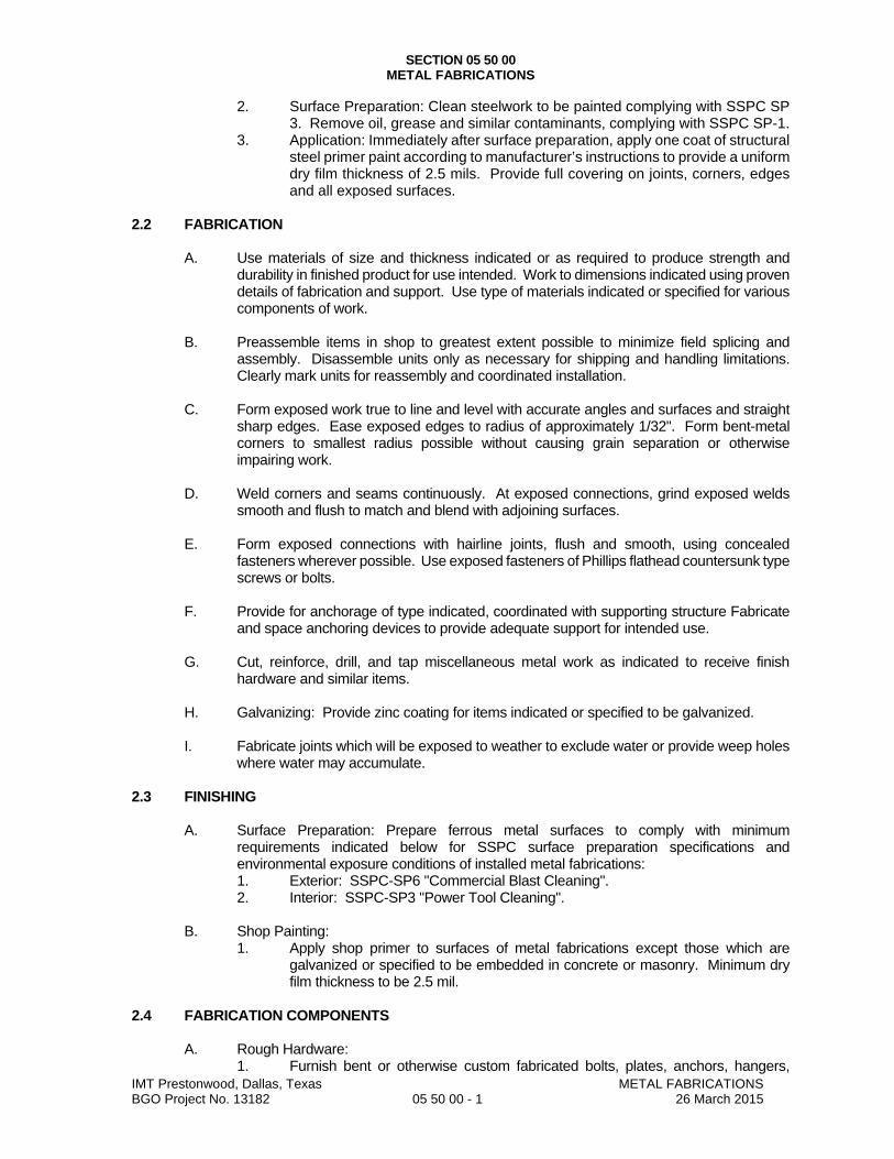
SECTION 05 50 00 METAL FABRICATIONS
IMT Prestonwood, Dallas, Texas METAL FABRICATIONS BGO Project No. 13182 05 50 00 - 1 26 March 2015
2. Surface Preparation: Clean steelwork to be painted complying with SSPC SP 3. Remove oil, grease and similar contaminants, complying with SSPC SP-1.
3. Application: Immediately after surface preparation, apply one coat of structural steel primer paint according to manufacturer’s instructions to provide a uniform dry film thickness of 2.5 mils. Provide full covering on joints, corners, edges and all exposed surfaces.
2.2 FABRICATION
A. Use materials of size and thickness indicated or as required to produce strength and durability in finished product for use intended. Work to dimensions indicated using proven details of fabrication and support. Use type of materials indicated or specified for various components of work.
B. Preassemble items in shop to greatest extent possible to minimize field splicing and
assembly. Disassemble units only as necessary for shipping and handling limitations. Clearly mark units for reassembly and coordinated installation.
C. Form exposed work true to line and level with accurate angles and surfaces and straight
sharp edges. Ease exposed edges to radius of approximately 1/32". Form bent-metal corners to smallest radius possible without causing grain separation or otherwise impairing work.
D. Weld corners and seams continuously. At exposed connections, grind exposed welds
smooth and flush to match and blend with adjoining surfaces.
E. Form exposed connections with hairline joints, flush and smooth, using concealed fasteners wherever possible. Use exposed fasteners of Phillips flathead countersunk type screws or bolts.
F. Provide for anchorage of type indicated, coordinated with supporting structure Fabricate
and space anchoring devices to provide adequate support for intended use.
G. Cut, reinforce, drill, and tap miscellaneous metal work as indicated to receive finish hardware and similar items.
H. Galvanizing: Provide zinc coating for items indicated or specified to be galvanized.
I. Fabricate joints which will be exposed to weather to exclude water or provide weep holes
where water may accumulate. 2.3 FINISHING
A. Surface Preparation: Prepare ferrous metal surfaces to comply with minimum requirements indicated below for SSPC surface preparation specifications and environmental exposure conditions of installed metal fabrications: 1. Exterior: SSPC-SP6 "Commercial Blast Cleaning". 2. Interior: SSPC-SP3 "Power Tool Cleaning".
B. Shop Painting:
1. Apply shop primer to surfaces of metal fabrications except those which are galvanized or specified to be embedded in concrete or masonry. Minimum dry film thickness to be 2.5 mil.
2.4 FABRICATION COMPONENTS
A. Rough Hardware: 1. Furnish bent or otherwise custom fabricated bolts, plates, anchors, hangers,

SECTION 05 50 00 METAL FABRICATIONS
IMT Prestonwood, Dallas, Texas METAL FABRICATIONS BGO Project No. 13182 05 50 00 - 1 26 March 2015
dowels and other miscellaneous steel and iron shapes required for framing and supporting woodwork, and for anchoring or securing woodwork to concrete or other structures.
2. Fabricate items to sizes, shapes and dimensions required. 3. Furnish malleable iron washers for heads and nuts which bear on wood structural
connections; elsewhere, furnish steel washers.
B. Loose Bearing and Leveling Plates: 1. Provide loose bearing and leveling plates for steel items bearing on masonry or
concrete construction, made flat, free from warps or twists, and of required thickness and bearing area.
2. Drill plates to receive anchor bolts and for grouting as required. 3. Prime paint after fabrication.
C. Loose Steel Lintels:
1. Provide loose structural steel lintels for openings and recesses in masonry walls and partitions shown.
2. Weld adjoining members together to form single unit where required. 3. Provide not less than 8" bearing at each side of opening. 4. Galvanize loose steel lintels to be installed in exterior walls.
D. Miscellaneous Framing and Supports:
1. Provide miscellaneous steel framing and supports which are not part of structural steel framework, required to complete work.
2. Fabricate miscellaneous units to sizes, shapes and profiles indicated or of required dimensions to receive work of related Sections.
3. Fabricate from structural steel shapes, plates, and steel bars, of welded construction using mitered joints for field connection.
4. Cut, drill, and tap units to receive hardware and similar items. 5. Equip units with integrally welded anchors for casting into concrete or building
into masonry. 6. Galvanize exterior miscellaneous frames and supports.
E. Miscellaneous Steel Trim:
1. Provide shapes and sizes for profiles shown. 2. Fabricate units from structural steel shapes, plates, and steel bars, with
continuously welded joints and smooth exposed edges. 3. Use concealed field splices wherever possible. 4. Provide cutouts, fittings, and anchorages as required for coordination of
assembly and installation with other work. 5. Galvanize exterior miscellaneous steel trim.
F. Shelf Angles:
1. Provide structural steel shelf angles of sizes indicated for attachment to concrete framing.
2. Provide slotted holes to receive 3/4" bolts, spaced not more than 4" from ends and not more than 16" o.c.
3. Galvanize shelf angles to be installed on exterior concrete framing.
G. Bollards: 1. 6" diameter x 6'-6" galvanized pipe with 0.322" minimum thick wall, for setting
3'-0" below grade. 2. Fill with concrete and form dome top.
H. Ladders:
1. Fabricate ladders for locations shown, with dimensions spacings, details and anchorages as indicated.
2. Comply with requirements of ANSI A14.3.

SECTION 05 50 00 METAL FABRICATIONS
IMT Prestonwood, Dallas, Texas METAL FABRICATIONS BGO Project No. 13182 05 50 00 - 1 26 March 2015
3. Fit rungs at centerline of side rails, plug weld, and grind smooth on outer rail faces.
4. Support each ladder at top and bottom and at intermediate points spaced not more than 5'-0" o.c.
5. Use welded or bolted steel brackets, designed for adequate support and anchorage, and to hold the ladder clear of wall surface as required.
6. Extend rails 42" above top rung, and return rails to wall or structure as required. 7. Provide non-slip surface on top of each rung, either by coating rung with
aluminum oxide granules set in epoxy resin adhesive, or by using type of manufactured rung which is filled with aluminum oxide grout.
PART 3 EXECUTION 3.1 EXAMINATION
A. Refer to Division 1, General Requirements – Execution for additional requirements on the Verification of existing conditions before starting Work.
B. Verification of Conditions: Verify that field measurements, surfaces, substrates and
conditions are as required, and ready to receive Work. C. Report in writing to Architect prevailing conditions that will adversely affect satisfactory
execution of the Work of this Section. Do not proceed with Work until unsatisfactory conditions have been corrected.
D. By beginning Work, Contractor accepts conditions and assumes responsibility for
correcting unsuitable conditions encountered at no additional cost to the Owner. 3.2 PREPARATION
A. Clean and strip primed steel items to bare metal where site welding is required.
B. Supply setting templates to the appropriate entities for steel items required to be cast into concrete or embedded in masonry.
3.3 INSTALLATION
A. Fastening to In-Place Construction: Provide anchorage devices and fasteners where necessary for securing miscellaneous fabrications to in-place construction; including threaded fasteners for concrete and masonry inserts, toggle bolts, through-bolts, lag bolts, wood screws, and other connectors as required.
B. Cutting, Fitting, and Placement:
1. Perform cutting, drilling and fitting required for installation of miscellaneous metal fabrications.
2. Set work accurately in location, alignment and elevation, plumb, level, true and free of rack, measured from established lines and levels.
3. Provide temporary bracing or anchors in formwork for items which are to be built into concrete masonry or similar construction.
4. Fit exposed connections accurately together to form tight, lightproof joints.
C. Field Welding: 1. Weld connections which are not to be left as exposed joints, but cannot be shop
welded because of shipping size limitations. 2. Grind exposed joints smooth and touch-up shop paint coat. 3. Do not weld, cut, or abrade surfaces of exterior units which have been hot-dip
galvanized after fabrication, and are intended for bolted or screwed field connections.

SECTION 05 50 00 METAL FABRICATIONS
IMT Prestonwood, Dallas, Texas METAL FABRICATIONS BGO Project No. 13182 05 50 00 - 1 26 March 2015
D. Setting Loose Plates:
1. Clean concrete and masonry bearing surfaces of any bond-reducing materials, and roughen to improve bond to surfaces.
2. Clean bottom surface of bearing plates. 3. Set loose leveling and bearing plates on wedges, or other adjustable devices. 4. After bearing members have been positioned and plumbed, tighten anchor bolts. 5. Do not remove wedges or shims, but if protruding, cut off flush with edge of
bearing plate before packing with grout. 6. Use nonmetallic, non-shrink grout. 7. Pack grout solidly between bearing surfaces and plates to ensure that no voids
remain. 3.4 FIELD PAINTING
A. General: 1. Clean spots and surfaces where primer coats have been removed, damaged, or
burned off, and clean field bolts and other field connections not concealed in finished Work.
2. Remove dirt, oil, and grease. 3. Apply a coat of specified paint. 4. Do not apply paint to wet, damp, oily, or improperly prepared surfaces.
B. Notify Architect when the work of this Section is ready to receive field painting.
1. Secure review by Architect prior to field painting. 2. Using spray or brush, as recommended by manufacturer of specified paint
material, fill all joints and corners and cover the surfaces with a smooth unbroken wet film sufficient to provide a dry film thickness of x 2.5 mil.
3.5 FIELD QUALITY CONTROL
A. Erection Inspecting: 1. The Owner's Testing and Inspecting Agency will inspect bolted connections,
shop and field welded connections, vertical and horizontal alignment and perform additional tests and re-inspections of work as are required by Owner, and will prepare test reports for the Owner's review.
2. The testing agency will conduct and interpret tests, and will state in each report whether inspected work complies with the requirements, specifically stating all deviations.
B. Correct deficiencies in products and installation found not to be in compliance with Contract Documents.
END OF SECTION

IMT Prestonwood, Dallas, Texas METAL STAIRS BGO Project No. 13182 055100 - 1 26 March 2015
SECTION 055100
METAL STAIRS
PART 1 GENERAL
1.1 SECTION INCLUDES A. Stairs with concrete treads. B. Structural steel stair framing and supports.
1.2 SUBMITTALS A. See Section 013000 - Administrative Requirements, for submittal procedures. B. Shop Drawings: Indicate profiles, sizes, connection attachments, reinforcing, anchorage, size and type
of fasteners, and accessories. 1. Indicate welded connections using standard AWS A2.4 welding symbols. Indicate net weld
lengths. 2. Include the design engineer's stamp or seal on each sheet of shop drawings.
C. Delegated Design Data: As required by authorities having jurisdiction. D. Fabricator's Qualification Statement: Provide documentation showing steel fabricator is accredited
under IAS AC172.
1.3 QUALITY ASSURANCE A. Structural Designer Qualifications: Professional Structural Engineer experienced in design of this work
and licensed in the State in which the Project is located, or personnel under direct supervision of such an engineer.
B. Welder Qualifications: Show certification of welders employed on the Work, verifying AWS qualification within the previous 12 months.
C. Fabricator Qualifications: A qualified steel fabricator that is accredited by the International Accreditation Service (IAS) Fabricator Inspection Program for Structural Steel (AC172).
PART 2 PRODUCTS
2.1 METAL STAIRS - GENERAL A. Metal Stairs: Provide stairs of the design specified, complete with landing platforms, vertical and
horizontal supports in conjunction with those supports designed by another Engineer, railings, and guards, fabricated accurately for anchorage to each other and to building structure. 1. Regulatory Requirements: Provide stairs and railings complying with the most stringent
requirements of local, state, and federal regulations; where requirements of the contract documents exceed those of regulations, comply with the contract documents.
2. Structural Design: Provide complete stair and railing assemblies complying with the applicable local code in conjunction with those supports designed by another Engineer
3. Dimensions: As indicated on drawings. 4. Shop assemble components; disassemble into largest practical sections suitable for transport
and access to site. 5. No sharp or rough areas on exposed travel surfaces and surfaces accessible to touch. 6. Separate dissimilar metals using paint or permanent tape.
B. Metal Jointing and Finish Quality Levels: 1. Commercial: Exposed joints as inconspicuous as possible, whether welded or mechanical;
underside of stair not covered by soffit IS considered exposed to view. a. Welded Joints: Intermittently welded on back side, filled with body putty, and sanded
smooth and flush. b. Welds Exposed to View: Ground smooth and flush. c. Mechanical Joints: Butted tight, flush, and hairline. d. Bolts Exposed to View: Countersunk flat or oval head bolts; no exposed nuts. e. Exposed Edges and Corners: Eased to small uniform radius. f. Metal Surfaces to be Painted: Sanded or ground smooth, suitable for satin or matte
finish. C. Fasteners: Same material or compatible with materials being fastened; type consistent with design
and specified quality level. D. Anchors and Related Components: Same material and finish as item to be anchored, except where
specifically indicated otherwise; provide all anchors and fasteners required.

IMT Prestonwood, Dallas, Texas METAL STAIRS BGO Project No. 13182 055100 - 2 26 March 2015
2.2 METAL STAIRS WITH CONCRETE TREADS A. Jointing and Finish Quality Level: Commercial, as defined above. B. Risers: Closed. C. Concrete Filled Metal Pan Treads: Metal pan with field-installed concrete fill.
1. Concrete Depth: 1-1/2 inches, minimum. 2. Tread Pan Material: Steel sheet. 3. Tread Pan Thickness: As required by design; 14 gage, 0.075 inch minimum. 4. Pan Anchorage to Stringers: Welded or bolted to carrier angles welded or bolted to stringers. 5. Concrete Reinforcement: None. 6. Concrete Strength: 5,000 psi at 28 days, minimum. 7. Air Content: 4 to 6 percent. 8. Cement Color: Natural gray. 9. Anchorage to Tread Pan: Epoxy adhesive. 10. Concrete Reinforcement: As required to resist live loading. 11. Concrete Finish: Broom finish.
D. Risers: Same material and thickness as tread pans. 1. Riser/Nosing Profile: Sloped riser with rounded nosing of minimum radius. 2. Nosing Depth: Not more than 1-1/2 inch overhang. 3. Nosing Return: Flush with top of concrete fill, not more than 1/2 inch wide.
E. Stringers: Rolled steel channels, including those decigned by another Engineer. F. Landings: Cast in place concrete, supported and reinforced as required to achieve design load
capacity. G. Railings: Steel pipe railings. H. Finish: Shop- or factory-prime painted.
2.3 MATERIALS A. Steel Sections: ASTM A 36/A 36M. B. Steel Plates: ASTM A6/A6M or ASTM A283/A283M. C. Steel Sheet: Hot- or cold-rolled, except use cold-rolled where finished work will be exposed to view.
1. Hot-Rolled Steel Sheet: ASTM A1011/A1011M, Designation CS (commercial steel). 2. Cold-Rolled Steel Sheet: ASTM A1008/A1008M, Designation CS (commercial steel).
D. Concrete Fill: Portland cement Type I, 3000 psi 28 day strength, 2 to 3 inch slump. E. Steel Bolts, Nuts, and Washers: ASTM A325 (ASTM A325M), Type 1 , and galvanized to ASTM
A153/A153M where connecting galvanized components. F. Welding Materials: AWS D1.1; type required for materials being welded. G. Shop and Touch-Up Primer: SSPC-Paint 15, complying with VOC limitations of authorities having
jurisdiction.
2.4 SHOP FINISHING A. Clean surfaces of rust, scale, grease, and foreign matter prior to finishing. B. Do not prime surfaces in direct contact with concrete or where field welding is required. C. Prime Painting: Use specified shop- and touch-up primer.
1. Preparation of Steel: In accordance with SSPC-SP 2, Hand Tool Cleaning. 2. Number of Coats: One.
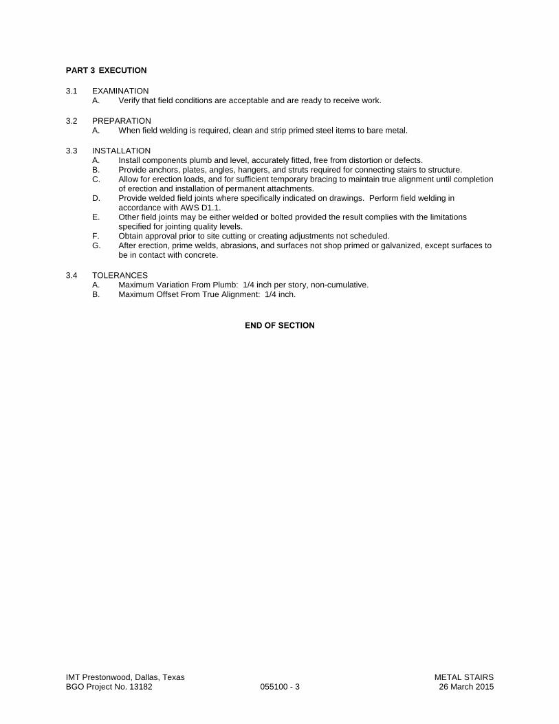
IMT Prestonwood, Dallas, Texas METAL STAIRS BGO Project No. 13182 055100 - 3 26 March 2015
PART 3 EXECUTION
3.1 EXAMINATION A. Verify that field conditions are acceptable and are ready to receive work.
3.2 PREPARATION A. When field welding is required, clean and strip primed steel items to bare metal.
3.3 INSTALLATION A. Install components plumb and level, accurately fitted, free from distortion or defects. B. Provide anchors, plates, angles, hangers, and struts required for connecting stairs to structure. C. Allow for erection loads, and for sufficient temporary bracing to maintain true alignment until completion
of erection and installation of permanent attachments. D. Provide welded field joints where specifically indicated on drawings. Perform field welding in
accordance with AWS D1.1. E. Other field joints may be either welded or bolted provided the result complies with the limitations
specified for jointing quality levels. F. Obtain approval prior to site cutting or creating adjustments not scheduled. G. After erection, prime welds, abrasions, and surfaces not shop primed or galvanized, except surfaces to
be in contact with concrete.
3.4 TOLERANCES A. Maximum Variation From Plumb: 1/4 inch per story, non-cumulative. B. Maximum Offset From True Alignment: 1/4 inch.
END OF SECTION
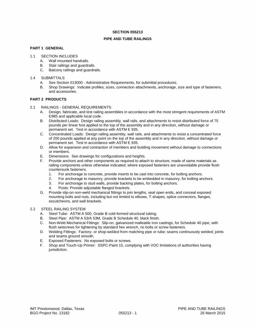
IMT Prestonwood, Dallas, Texas PIPE AND TUBE RAILINGS BGO Project No. 13182 055213 - 1 26 March 2015
SECTION 055213
PIPE AND TUBE RAILINGS
PART 1 GENERAL
1.1 SECTION INCLUDES
A. Wall mounted handrails.
B. Stair railings and guardrails.
C. Balcony railings and guardrails.
1.4 SUBMITTALS
A. See Section 013000 - Administrative Requirements, for submittal procedures.
B. Shop Drawings: Indicate profiles, sizes, connection attachments, anchorage, size and type of fasteners, and accessories.
PART 2 PRODUCTS
2.1 RAILINGS - GENERAL REQUIREMENTS
A. Design, fabricate, and test railing assemblies in accordance with the most stringent requirements of ASTM E985 and applicable local code.
B. Distributed Loads: Design railing assembly, wall rails, and attachments to resist distributed force of 75 pounds per linear foot applied to the top of the assembly and in any direction, without damage or permanent set. Test in accordance with ASTM E 935.
C. Concentrated Loads: Design railing assembly, wall rails, and attachments to resist a concentrated force of 200 pounds applied at any point on the top of the assembly and in any direction, without damage or permanent set. Test in accordance with ASTM E 935.
D. Allow for expansion and contraction of members and building movement without damage to connections or members.
E. Dimensions: See drawings for configurations and heights.
F. Provide anchors and other components as required to attach to structure, made of same materials as railing components unless otherwise indicated; where exposed fasteners are unavoidable provide flush countersunk fasteners.
1. For anchorage to concrete, provide inserts to be cast into concrete, for bolting anchors.
2. For anchorage to masonry, provide brackets to be embedded in masonry, for bolting anchors.
3. For anchorage to stud walls, provide backing plates, for bolting anchors.
4. Posts: Provide adjustable flanged brackets.
G. Provide slip-on non-weld mechanical fittings to join lengths, seal open ends, and conceal exposed mounting bolts and nuts, including but not limited to elbows, T-shapes, splice connectors, flanges, escutcheons, and wall brackets.
2.2 STEEL RAILING SYSTEM
A. Steel Tube: ASTM A 500, Grade B cold-formed structural tubing.
B. Steel Pipe: ASTM A 53/A 53M, Grade B Schedule 40, black finish.
C. Non-Weld Mechanical Fittings: Slip-on, galvanized malleable iron castings, for Schedule 40 pipe, with flush setscrews for tightening by standard hex wrench, no bolts or screw fasteners.
D. Welding Fittings: Factory- or shop-welded from matching pipe or tube; seams continuously welded; joints and seams ground smooth.
E. Exposed Fasteners: No exposed bolts or screws.
F. Shop and Touch-Up Primer: SSPC-Paint 15, complying with VOC limitations of authorities having jurisdiction.

IMT Prestonwood, Dallas, Texas PIPE AND TUBE RAILINGS BGO Project No. 13182 055213 - 2 26 March 2015
2.3 FABRICATION
A. Accurately form components to suit specific project conditions and for proper connection to building structure.
B. Fit and shop assemble components in largest practical sizes for delivery to site.
C. Fabricate components with joints tightly fitted and secured. Provide spigots and sleeves to accommodate site assembly and installation.
D. Welded Joints:
1. Exterior Components: Continuously seal joined pieces by intermittent welds and plastic filler. Drill condensate drainage holes at bottom of members at locations that will not encourage water intrusion.
2. Interior Components: Continuously seal joined pieces by intermittent welds and plastic filler.
3. Grind exposed joints flush and smooth with adjacent finish surface. Make exposed joints butt tight, flush, and hairline. Ease exposed edges to small uniform radius.
PART 3 EXECUTION
3.1 EXAMINATION
A. Verify that field conditions are acceptable and are ready to receive work.
3.2 PREPARATION
A. Clean and strip primed steel items to bare metal where site welding is required.
B. Supply items required to be cast into concrete or embedded in masonry with setting templates, for installation as work of other sections.
3.3 INSTALLATION
A. Install in accordance with manufacturer's instructions.
B. Install components plumb and level, accurately fitted, free from distortion or defects, with tight joints.
C. Anchor railings securely to structure.
D. Conceal anchor bolts and screws whenever possible. Where not concealed, use flush countersunk fastenings.
3.4 TOLERANCES
A. Maximum Variation From Plumb: 1/4 inch per floor level, non-cumulative.
B. Maximum Offset From True Alignment: 1/4 inch.
C. Maximum Out-of-Position: 1/4 inch.
END OF SECTION

IMT Prestonwood, Dallas, Texas DECORATIVE RAILINGS BGO Project No. 13182 057300 - 1 26 March 2015
SECTION 057300
DECORATIVE RAILINGS
PART 1 - GENERAL
1.1 RELATED DOCUMENTS A. Drawings and general provisions of the Contract, including General and Supplementary Conditions and
Division 01 Specification Sections, apply to this Section.
1.2 SUMMARY A. Section Includes:
1. Post-supported railings with glass infill.
1.3 DEFINITIONS A. Railings: Guards, handrails, and similar devices used for protection of occupants at open-sided floor
areas, pedestrian guidance and support, visual separation, or wall protection.
1.4 PERFORMANCE REQUIREMENTS A. Delegated Design: Design railings, including comprehensive engineering analysis by a qualified
professional engineer, using performance requirements and design criteria indicated. B. Structural capacities: Handrails, guardrails, and their supports must be designed for 50 lbs per linear foot,
applied in any direction at the top of the top rail, and a concentrated load of 200 lbs applied in any direction at any location along the top of the top rail
C. General: In engineering railings to withstand structural loads indicated, determine allowable design working stresses of railing materials based on the following: 1. Aluminum: The lesser of minimum yield strength divided by 1.65 or minimum ultimate tensile
strength divided by 1.95. 2. Stainless Steel: 60 percent of minimum yield strength. 3. Glass: 25 percent of mean modulus of rupture (50 percent probability of breakage), as listed in
"Mechanical Properties" in AAMA's Aluminum Curtain Wall Series No. 12, "Structural Properties of Glass."
D. Thermal Movements: Allow for thermal movements from ambient and surface temperature changes acting on exterior metal fabrications by preventing buckling, opening of joints, overstressing of components, failure of connections, and other detrimental effects. 1. Temperature Change: 120 deg F, ambient; 180 deg F, material surfaces.
E. Control of Corrosion: Prevent galvanic action and other forms of corrosion by insulating metals and other materials from direct contact with incompatible materials.
1.5 SUBMITTALS A. Product Data: For the following:
1. Manufacturer's product lines of railings assembled from standard components. B. Sustainable Submittals:
1. Product data for products having recycled content, documentation indicating percentages by weight of postconsumer and preconsumer recycled content. Include statement indicating costs for each product having recycled content.
C. Shop Drawings: Include plans, elevations, sections, details, and attachments to other work. D. Samples for Verification: For each type of exposed finish required.
1. Sections of each distinctly different linear railing member, including handrails, top rails, posts, and balusters.
2. Each type of glass required. 3. Fittings and brackets. 4. Welded connections. 5. Assembled Samples of railing systems, made from full-size components, including top rail, post,
handrail, and infill. Show method of finishing members at intersections. Samples need not be full height.
E. Delegated-Design Submittal: For installed products indicated to comply with performance requirements and design criteria, including analysis data signed and sealed by the qualified professional engineer responsible for their preparation.
F. Qualification Data: For qualified professional engineer .

IMT Prestonwood, Dallas, Texas DECORATIVE RAILINGS BGO Project No. 13182 057300 - 2 26 March 2015
1.6 QUALITY ASSURANCE A. Source Limitations: Obtain each type of railing from single source from single manufacturer. B. Product Options: Information on Drawings and in Specifications establishes requirements for system's
aesthetic effects and performance characteristics. Aesthetic effects are indicated by dimensions, arrangements, alignment, and profiles of components and assemblies as they relate to sightlines, to one another, and to adjoining construction. Performance characteristics are indicated by criteria subject to verification by one or more methods including structural analysis, preconstruction testing, field testing, and in-service performance. 1. Do not modify intended aesthetic effects, as judged solely by Architect, except with Architect's
approval. If modifications are proposed, submit comprehensive explanatory data to Architect for review.
C. Product Options: Drawings indicate size, profiles, and dimensional requirements of railings and are based on the specific system indicated. Refer to Division 01 Section "Product Requirements." 1. Do not modify intended aesthetic effects, as judged solely by Architect, except with Architect's
approval. If modifications are proposed, submit comprehensive explanatory data to Architect for review.
D. Welding Qualifications: Qualify procedures and personnel according to the following: 1. AWS D1.1/D1.1M, "Structural Welding Code - Steel." 2. AWS D1.2/D1.2M, "Structural Welding Code - Aluminum." 3. AWS D1.6, "Structural Welding Code - Stainless Steel."
E. Safety Glazing Labeling: Permanently mark glass with certification label of the SGCC or another certification agency acceptable to authorities having jurisdiction . Label shall indicate manufacturer's name, type of glass, thickness, and safety glazing standard with which glass complies.
F. Mockups: Build mockups to verify selections made under sample submittals and to demonstrate aesthetic effects and set quality standards for fabrication and installation. 1. Build mockups as shown on Drawings. If not indicated on drawings follow requirements below. 2. Build mockups for each form and finish of railing consisting of two posts, top rail, infill area, and
anchorage system components that are full height and are not less than 24 inches in length.
1.7 PROJECT CONDITIONS A. Field Measurements: Verify actual locations of walls and other construction contiguous with railings by
field measurements before fabrication and indicate measurements on Shop Drawings.
1.8 COORDINATION AND SCHEDULING A. Coordinate selection of shop primers with topcoats to be applied over them. Comply with paint and
coating manufacturers' written recommendations to ensure that shop primers and topcoats are compatible with one another.
B. Coordinate installation of anchorages for railings. Furnish setting drawings, templates, and directions for installing anchorages, including sleeves, concrete inserts, anchor bolts, and items with integral anchors, that are to be embedded in concrete or masonry. Deliver such items to Project site in time for installation.
C. Schedule installation so wall attachments are made only to completed walls. Do not support railings temporarily by any means that do not suit structural performance requirements.
PART 2 - PRODUCTS
2.1 MANUFACTURERS A. Manufacturers: Subject to compliance with requirements, provide products by one of the following:
1. Glass Railings: a. Viva Railings. b. P&P Artec. c. Blum, Julius & Co., Inc. d. Blumcraft of Pittsburgh. e. Livers Bronze Co.

IMT Prestonwood, Dallas, Texas DECORATIVE RAILINGS BGO Project No. 13182 057300 - 3 26 March 2015
2.2 METALS, GENERAL A. Metal Surfaces, General: Provide materials with smooth surfaces, without seam marks, roller marks,
rolled trade names, stains, discolorations, or blemishes. B. Brackets, Flanges, and Anchors: Same metal and finish as supported rails unless otherwise indicated.
1. Provide cast-metal brackets with flange tapped for concealed anchorage to threaded hanger bolt. 2. Provide either formed- or cast-metal brackets with predrilled hole for exposed bolt anchorage. 3. Provide formed-steel brackets with predrilled hole for bolted anchorage and with snap-on cover that
matches rail finish and conceals bracket base and bolt head. 4. Provide extruded-aluminum brackets with interlocking pieces that conceal anchorage. Locate set
screws on bottom of bracket.
2.3 STAINLESS STEEL A. Tubing: ASTM A 554, Grade MT 304. B. Pipe: ASTM A 312/A 312M, Grade TP 304. C. Castings: ASTM A 743/A 743M, Grade CF 8 or CF 20. D. Sheet, Strip, Plate, and Flat Bar: ASTM A 666, Type 304. E. Bars and Shapes: ASTM A 276, Type 304.
2.4 GLASS AND GLAZING MATERIALS A. Tempered Glass: ASTM C 1048, Kind FT (fully tempered), Condition A (uncoated), Type 1 (transparent
flat glass), Quality-Q3. Provide products that have been tested for surface and edge compression according to ASTM C 1048 and for impact strength according to 16 CFR 1201 for Category II materials. 1. Glass Color: Clear. 2. Thickness for Structural Glass Balusters: As required by structural loads, but not less than 12.0
mm. 3. Thickness for Glass Infill Panels: As required by structural loads, but not less than 6.0 mm. 4. Thickness: As indicated on Drawings.
B. Glazing Gaskets for Glass Infill Panels: Glazing gaskets and related accessories recommended or supplied by railing manufacturer for installing glass infill panels in post-supported railings.
2.5 FASTENERS A. Fastener Materials: Unless otherwise indicated, provide the following:
1. Aluminum Components: Type 304 stainless-steel fasteners. 2. Stainless-Steel Components: Type 304 stainless-steel fasteners. 3. Dissimilar Metals: Type 304 stainless-steel fasteners.
B. Fasteners for Anchoring to Other Construction: Select fasteners of type, grade, and class required to produce connections suitable for anchoring railings to other types of construction indicated.
C. Provide concealed fasteners for interconnecting railing components and for attaching railings to other work unless exposed fasteners are unavoidable. 1. Provide Phillips flat-head machine screws for exposed fasteners unless otherwise indicated.
D. Anchors, General: Anchors capable of sustaining, without failure, a load equal to six times the load imposed when installed in unit masonry and four times the load imposed when installed in concrete, as determined by testing according to ASTM E 488, conducted by a qualified independent testing agency.
E. Post-Installed Anchors: Torque-controlled expansion anchors. 1. Material for Interior Locations: Carbon-steel components zinc plated to comply with ASTM B 633
or ASTM F 1941, Class Fe, unless otherwise indicated. 2. Material for Exterior Locations and Where Stainless Steel Is Indicated: Alloy Group 1stainless-steel
bolts, ASTM F 593, and nuts, ASTM F 594.
2.6 MISCELLANEOUS MATERIALS A. Welding Rods and Bare Electrodes: Select according to AWS specifications for metal alloy welded.
1. For aluminum railings, provide type and alloy as recommended by producer of metal to be welded and as required for color match, strength, and compatibility in fabricated items.
B. Non-shrink, Non-metallic Grout: Factory-packaged, non-staining, non-corrosive, nongaseous grout complying with ASTM C 1107. Provide grout specifically recommended by manufacturer for interior and exterior applications.

IMT Prestonwood, Dallas, Texas DECORATIVE RAILINGS BGO Project No. 13182 057300 - 4 26 March 2015
2.7 FABRICATION A. General: Fabricate railings to comply with requirements indicated for design, dimensions, member sizes
and spacing, details, finish, and anchorage. B. Assemble railings in the shop to greatest extent possible to minimize field splicing and assembly.
Disassemble units only as necessary for shipping and handling limitations. Clearly mark units for reassembly and coordinated installation. Use connections that maintain structural value of joined pieces.
C. Make up wire-rope assemblies in the shop to field-measured dimensions with fittings machine swaged. Minimize amount of turnbuckle take-up used for dimensional adjustment so maximum amount is available for tensioning wire ropes. Tag wire-rope assemblies and fittings to identify installation locations and orientations for coordinated installation.
D. Cut, drill, and punch metals cleanly and accurately. Remove burrs and ease edges to a radius of approximately 1/32 inch unless otherwise indicated. Remove sharp or rough areas on exposed surfaces.
E. Form work true to line and level with accurate angles and surfaces. F. Fabricate connections that will be exposed to weather in a manner to exclude water. Provide weep holes
where water may accumulate. Locate weep holes in inconspicuous locations. G. Cut, reinforce, drill, and tap as indicated to receive finish hardware, screws, and similar items. H. Connections: Fabricate railings with welded connections unless otherwise indicated. I. Welded Connections: Cope components at connections to provide close fit, or use fittings designed for
this purpose. Weld all around at connections, including at fittings. 1. Use materials and methods that minimize distortion and develop strength and corrosion resistance
of base metals. 2. Obtain fusion without undercut or overlap. 3. Remove flux immediately. 4. At exposed connections, finish exposed welds to comply with NOMMA's "Voluntary Joint Finish
Standards" for Type 1 welds: no evidence of a welded joint. J. Welded Connections for Aluminum Pipe: Fabricate railings to interconnect members with concealed
internal welds that eliminate surface grinding, using manufacturer's standard system of sleeve and socket fittings.
K. Mechanical Connections: Connect members with concealed mechanical fasteners and fittings. Fabricate members and fittings to produce flush, smooth, rigid, hairline joints. 1. Fabricate splice joints for field connection using an epoxy structural adhesive if this is
manufacturer's standard splicing method. L. Form changes in direction as follows:
1. By bending. M. Bend members in jigs to produce uniform curvature for each configuration required; maintain cross section
of member throughout entire bend without buckling, twisting, cracking, or otherwise deforming exposed surfaces of components.
N. Close exposed ends of hollow railing members with prefabricated end fittings. O. Provide wall returns at ends of wall-mounted handrails unless otherwise indicated. Close ends of returns,
unless clearance between end of rail and wall is 1/4 inch or less. P. Brackets, Flanges, Fittings, and Anchors: Provide wall brackets, flanges, miscellaneous fittings, and
anchors to interconnect railing members to other work unless otherwise indicated. 1. At brackets and fittings fastened to plaster or gypsum board partitions, provide crush-resistant
fillers, or other means to transfer loads through wall finishes to structural supports and prevent bracket or fitting rotation and crushing of substrate.
Q. Provide inserts and other anchorage devices for connecting railings to concrete or masonry work. Fabricate anchorage devices capable of withstanding loads imposed by railings. Coordinate anchorage devices with supporting structure.
R. For railing posts set in concrete, provide [steel] [stainless-steel] sleeves not less than 6 inches long with inside dimensions not less than 1/2 inch greater than outside dimensions of post, with metal plate forming bottom closure.
2.8 GLAZING PANEL FABRICATION A. General: Fabricate to sizes and shapes required; provide for proper edge clearance and bite on glazing
panels. 1. Clean-cut or flat-grind edges at butt-glazed sealant joints to produce square edges with slight
chamfers at junctions of edges and faces 2. Grind smooth exposed edges, including those at open joints, to produce square edges with slight
chamfers at junctions of edges and faces. B. Infill Panels: Provide tempered laminated, heat-strengthened glass panels[ for both straight and curved
sections].

IMT Prestonwood, Dallas, Texas DECORATIVE RAILINGS BGO Project No. 13182 057300 - 5 26 March 2015
2.9 GENERAL FINISH REQUIREMENTS A. Comply with NAAMM's "Metal Finishes Manual for Architectural and Metal Products" for recommendations
for applying and designating finishes. B. Protect mechanical finishes on exposed surfaces from damage by applying a strippable, temporary
protective covering before shipment. C. Provide exposed fasteners with finish matching appearance, including color and texture, of railings.
2.10 STAINLESS-STEEL FINISHES A. Surface Preparation: Remove tool and die marks and stretch lines, or blend into finish. B. Polished Finishes: Grind and polish surfaces to produce uniform finish, free of cross scratches. C. Directional Satin Finish: No. 4. D. When polishing is completed, passivate and rinse surfaces. Remove embedded foreign matter and leave
surfaces chemically clean.
PART 3 - EXECUTION
3.1 EXAMINATION A. Examine plaster and gypsum board assemblies, where reinforced to receive anchors, to verify that
locations of concealed reinforcements have been clearly marked for Installer. Locate reinforcements and mark locations if not already done.
3.2 INSTALLATION, GENERAL A. Fit exposed connections together to form tight, hairline joints. B. Perform cutting, drilling, and fitting required for installing railings. Set railings accurately in location,
alignment, and elevation; measured from established lines and levels and free of rack. 1. Do not weld, cut, or abrade surfaces of railing components that have been coated or finished after
fabrication and that are intended for field connection by mechanical or other means without further cutting or fitting.
2. Set posts plumb within a tolerance of 1/16 inch in 3 feet. 3. Align rails so variations from level for horizontal members and variations from parallel with rake of
steps and ramps for sloping members do not exceed 1/4 inch in 12 feet. C. Corrosion Protection: Coat concealed surfaces of aluminum that will be in contact with grout, concrete,
masonry, wood, or dissimilar metals, with a heavy coat of bituminous paint. D. Adjust railings before anchoring to ensure matching alignment at abutting joints. E. Fastening to In-Place Construction: Use anchorage devices and fasteners where necessary for securing
railings and for properly transferring loads to in-place construction.
3.3 RAILING CONNECTIONS A. Non-welded Connections: Use mechanical or adhesive joints for permanently connecting railing
components. Use wood blocks and padding to prevent damage to railing members and fittings. Seal recessed holes of exposed locking screws using plastic cement filler colored to match finish of railings.
B. Welded Connections: Use fully welded joints for permanently connecting railing components. Comply with requirements for welded connections in "Fabrication" Article whether welding is performed in the shop or in the field.
3.4 ANCHORING POSTS A. Use steel pipe sleeves preset and anchored into concrete for installing posts. After posts have been
inserted into sleeves, fill annular space between post and sleeve with non-shrink, non-metallic grout, mixed and placed to comply with anchoring material manufacturer's written instructions.
B. Form or core-drill holes not less than 5 inches deep and 3/4 inch larger than OD of post for installing posts in concrete. Clean holes of loose material, insert posts, and fill annular space between post and concrete with [non-shrink, non-metallic grout] [or] [anchoring cement], mixed and placed to comply with anchoring material manufacturer's written instructions.
C. Cover anchorage joint with flange of same metal as post, welded to post after placing anchoring material. D. Leave anchorage joint exposed with anchoring material flush with adjacent surface. E. Anchor posts to metal surfaces with flanges, angle type, or floor type as required by conditions, connected
to posts and to metal supporting members as follows: 1. For aluminum railings, attach posts as indicated using fittings designed and engineered for this
purpose. 2. For stainless-steel railings, weld flanges to posts and bolt to metal-supporting surfaces. 3. For steel railings, weld flanges to posts and bolt to metal-supporting surfaces.
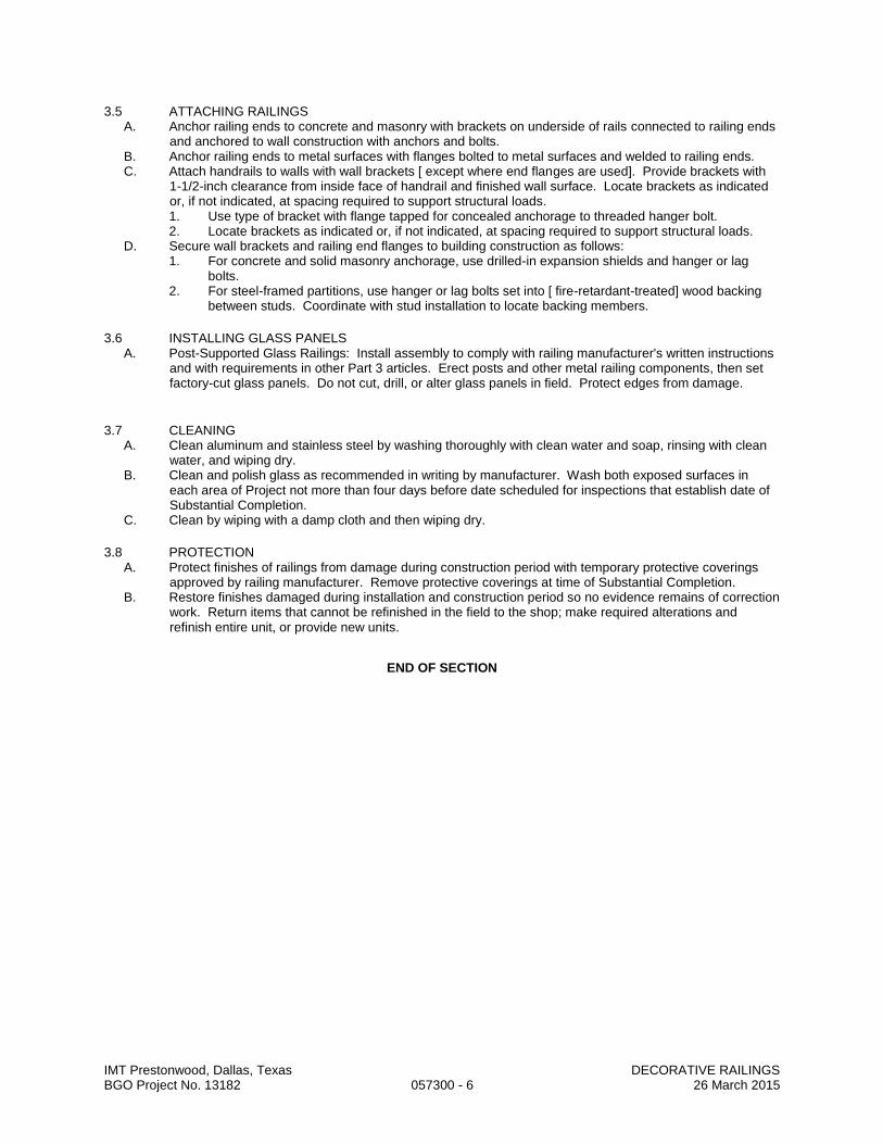
IMT Prestonwood, Dallas, Texas DECORATIVE RAILINGS BGO Project No. 13182 057300 - 6 26 March 2015
3.5 ATTACHING RAILINGS A. Anchor railing ends to concrete and masonry with brackets on underside of rails connected to railing ends
and anchored to wall construction with anchors and bolts. B. Anchor railing ends to metal surfaces with flanges bolted to metal surfaces and welded to railing ends. C. Attach handrails to walls with wall brackets [ except where end flanges are used]. Provide brackets with
1-1/2-inch clearance from inside face of handrail and finished wall surface. Locate brackets as indicated or, if not indicated, at spacing required to support structural loads. 1. Use type of bracket with flange tapped for concealed anchorage to threaded hanger bolt. 2. Locate brackets as indicated or, if not indicated, at spacing required to support structural loads.
D. Secure wall brackets and railing end flanges to building construction as follows: 1. For concrete and solid masonry anchorage, use drilled-in expansion shields and hanger or lag
bolts. 2. For steel-framed partitions, use hanger or lag bolts set into [ fire-retardant-treated] wood backing
between studs. Coordinate with stud installation to locate backing members.
3.6 INSTALLING GLASS PANELS A. Post-Supported Glass Railings: Install assembly to comply with railing manufacturer's written instructions
and with requirements in other Part 3 articles. Erect posts and other metal railing components, then set factory-cut glass panels. Do not cut, drill, or alter glass panels in field. Protect edges from damage.
3.7 CLEANING A. Clean aluminum and stainless steel by washing thoroughly with clean water and soap, rinsing with clean
water, and wiping dry. B. Clean and polish glass as recommended in writing by manufacturer. Wash both exposed surfaces in
each area of Project not more than four days before date scheduled for inspections that establish date of Substantial Completion.
C. Clean by wiping with a damp cloth and then wiping dry.
3.8 PROTECTION A. Protect finishes of railings from damage during construction period with temporary protective coverings
approved by railing manufacturer. Remove protective coverings at time of Substantial Completion. B. Restore finishes damaged during installation and construction period so no evidence remains of correction
work. Return items that cannot be refinished in the field to the shop; make required alterations and refinish entire unit, or provide new units.
END OF SECTION
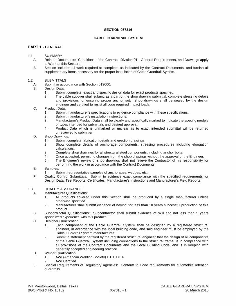
IMT Prestonwood, Dallas, Texas CABLE GUARDRAIL SYSTEM BGO Project No. 13182 057316 - 1 26 March 2015
SECTION 057316
CABLE GUARDRAIL SYSTEM
PART 1 - GENERAL
1.1 SUMMARY A. Related Documents: Conditions of the Contract, Division 01 - General Requirements, and Drawings apply
to Work of this Section. B. Section includes all work required to complete, as indicated by the Contract Documents, and furnish all
supplementary items necessary for the proper installation of Cable Guardrail System.
1.2 SUBMITTALS A. Submit in accordance with Section 013000. B. Design Data:
1. Submit complete, exact and specific design data for exact products specified. 2. The cable supplier shall submit, as a part of the shop drawing submittal, complete stressing details
and provisions for ensuring proper anchor set. Shop drawings shall be sealed by the design engineer and certified to resist all code required impact loads.
C. Product Data: 1. Submit manufacturer's specifications to evidence compliance with these specifications. 2. Submit manufacturer's installation instructions. 3. Manufacturer's Product Data shall be clearly and specifically marked to indicate the specific models
or types intended for submittals and desired approval. 4. Product Data which is unmarked or unclear as to exact intended submittal will be returned
unreviewed to submitter. D. Shop Drawings:
1. Submit complete fabrication details and erection drawings. 2. Show complete details of anchorage components, stressing procedures including elongation
calculations. 3. Complete shop drawings for all structural steel components, including anchor bolts. 4. Once accepted, permit no changes from the shop drawings without the approval of the Engineer. 5. The Engineer's review of shop drawings shall not relieve the Contractor of his responsibility for
performing the work in accordance with the Contract Documents. E. Samples:
1. Submit representative samples of anchorages, wedges, etc. F. Quality Control Submittals: Submit to evidence exact compliance with the specified requirements for
Design Data, Test Reports, Certificates, Manufacturer's Instructions and Manufacturer's Field Reports.
1.3 QUALITY ASSURANCE A. Manufacturer Qualifications:
1. All products covered under this Section shall be produced by a single manufacturer unless otherwise specified.
2. Manufacturer shall submit evidence of having not less than 10 years successful production of this product.
B. Subcontractor Qualifications: Subcontractor shall submit evidence of skill and not less than 5 years specialized experience with this product.
C. Designer Qualification: 1. Each component of the Cable Guardrail System shall be designed by a registered structural
engineer, in accordance with the local building code, and said engineer must be employed by the Cable Guardrail System manufacturer.
2. Submit a statement certified by the registered structural engineer that the design of all components of the Cable Guardrail System including connections to the structural frame, is in compliance with all provisions of the Contract Documents and the Local Building Code, and is in keeping with generally accepted engineering practice.
D. Welder Qualification: 1. AWI (American Welding Society) D1.1, D1.4 2. AWI Certified
E. Special Requirements of Regulatory Agencies: Conform to Code requirements for automobile retention guardrails.
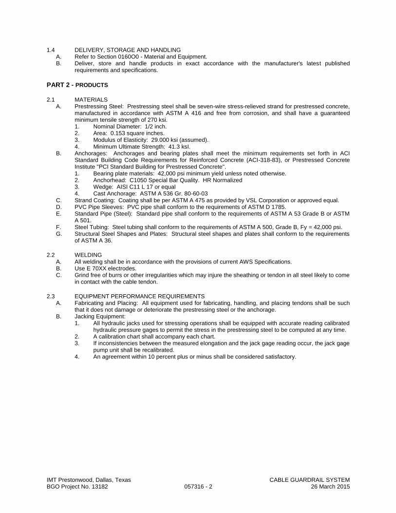
IMT Prestonwood, Dallas, Texas CABLE GUARDRAIL SYSTEM BGO Project No. 13182 057316 - 2 26 March 2015
1.4 DELIVERY, STORAGE AND HANDLING A. Refer to Section 0160O0 - Material and Equipment. B. Deliver, store and handle products in exact accordance with the manufacturer's latest published
requirements and specifications.
PART 2 - PRODUCTS
2.1 MATERIALS A. Prestressing Steel: Prestressing steel shall be seven-wire stress-relieved strand for prestressed concrete,
manufactured in accordance with ASTM A 416 and free from corrosion, and shall have a guaranteed minimum tensile strength of 270 ksi. 1. Nominal Diameter: 1/2 inch. 2. Area: 0.153 square inches. 3. Modulus of Elasticity: 29.000 ksi (assumed). 4. Minimum Ultimate Strength: 41.3 ksI.
B. Anchorages: Anchorages and bearing plates shall meet the minimum requirements set forth in ACI Standard Building Code Requirements for Reinforced Concrete (ACI-318-83), or Prestressed Concrete Institute "PCI Standard Building for Prestressed Concrete". 1. Bearing plate materials: 42,000 psi minimum yield unless noted otherwise. 2. Anchorhead: C1050 Special Bar Quality. HR Normalized 3. Wedge: AISI C11 L 17 or equal 4. Cast Anchorage: ASTM A 536 Gr. 80-60-03
C. Strand Coating: Coating shall be per ASTM A 475 as provided by VSL Corporation or approved equal. D. PVC Pipe Sleeves: PVC pipe shall conform to the requirements of ASTM D 1785. E. Standard Pipe (Steel): Standard pipe shall conform to the requirements of ASTM A 53 Grade B or ASTM
A 501. F. Steel Tubing: Steel tubing shall conform to the requirements of ASTM A 500, Grade B, Fy = 42,000 psi. G. Structural Steel Shapes and Plates: Structural steel shapes and plates shall conform to the requirements
of ASTM A 36.
2.2 WELDING A. All welding shall be in accordance with the provisions of current AWS Specifications. B. Use E 70XX electrodes. C. Grind free of burrs or other irregularities which may injure the sheathing or tendon in all steel likely to come
in contact with the cable tendon.
2.3 EQUIPMENT PERFORMANCE REQUIREMENTS A. Fabricating and Placing: All equipment used for fabricating, handling, and placing tendons shall be such
that it does not damage or deteriorate the prestressing steel or the anchorage. B. Jacking Equipment:
1. All hydraulic jacks used for stressing operations shall be equipped with accurate reading calibrated hydraulic pressure gages to permit the stress in the prestressing steel to be computed at any time.
2. A calibration chart shall accompany each chart. 3. If inconsistencies between the measured elongation and the jack gage reading occur, the jack gage
pump unit shall be recalibrated. 4. An agreement within 10 percent plus or minus shall be considered satisfactory.

IMT Prestonwood, Dallas, Texas CABLE GUARDRAIL SYSTEM BGO Project No. 13182 057316 - 3 26 March 2015
2.4 SOURCE QUALITY CONTROL (MANUFACTURER/FABRICATOR) A. Tests:
1. Mill Tests: Prestressing Steel: a. Submit certified mill reports on the prestressing steel used to the Engineer. b. Show the ultimate strength, the modulus of elasticity, and percent elongation at rupture.
These values shall conform to latest revisions of pertinent ASTM Specifications. B. Individual Tests (Anchorage): Submit reports on three individual tests performed in accordance with the
following criteria for review by the Engineer. 1. Static Tests:
a. Stressing anchorages shall develop at least 95 percent of the minimum specified ultimate strength of the prestressing steel without exceeding anticipated set.
b. The total elongation under ultimate load of the tendon shall not be less than 2 percent measured in a minimum gage length of 10 feet.
c. The tendon assembly shall be tested in such a manner as to allow accurate determination of the yield strength, ultimate strength, and percent elongation of the complete tendon to ensure compliance with this specification.
d. The specimen used for the static test need not be one that has been subjected to dynamic loading.
2. Perform dynamic tests on representative specimens and the tendons shall withstand, without failure, 100,000 cycles from 60 percent to 66 percent of the minimum specified ultimate strength, and also 50 cycles from 40 percent to 80 percent of the minimum specified ultimate strength.
PART 3 - EXECUTION
3.1 EXAMINATION A. Examine and verify that receiving substrate surfaces of the structure have no defects or errors which
would result in poor or potentially defective application or cause latent defects in workmanship. B. Report any unsatisfactory conditions to the Architect. C. Starting installation shall imply acceptance of surfaces.
3.2 PREPARATION A. Prepare the structure to insure proper and adequate structural support for the materials specified. B. Prepare substrate surfaces to insure proper and adequate installation, in exact accordance with the
Contract Documents and approved Shop Drawings, or manufacturer's requirements. C. Field measure and verify dimensions as required. D. Protect adjacent areas or surfaces from damage as a result of the Work of this Section.
3.3 INSTALLATION A. Install in exact accordance with manufacturer's latest published requirements, instructions, specifications,
details and approved shop drawings. B. Interface with Other Products: Coordinate and cooperate with all supporting, adjacent, contiguous or
otherwise related materials trades. C. Installation/Erection Tolerances (Stressing): Stress cables so that, after final seating of wedges, the
remaining force per cable is not less than 2,000 pounds and not more than 2,500 pounds. D. Install all posts and pipe sleeves in proper alignment to prevent injury to the tendon sheathing when
stressing. E. Take precautions when placing pipe sleeves and grommets in column forms to prevent movement when
placing concrete. F. If anchor bolts are set before placing concrete, check the location for proper alignment prior to beginning
pour.
3.4 GROUTING ANCHOR RECESSES A. After all stressing cables are completed, grout the anchor recesses flush with the face of column or other
support. B. Remove excess tendons to a length of 1/2 inch inside the face of column. C. Complete this process by means of an acetylene torch unit turned at an angle to the strand so as not to
overheat the wedges. D. After removal of the excess strand tail, clean the anchorage recess of all foreign material and fill with a
non-shrink, nonmetallic, high-density grout material.

IMT Prestonwood, Dallas, Texas CABLE GUARDRAIL SYSTEM BGO Project No. 13182 057316 - 4 26 March 2015
3.5 ADJUSTING A. Comply with requirements of Section 017000. B. Adjust and leave the Cable Guardrail System in perfect working order.
3.6 CLEANING A. Clean in exact accordance with Section 01700. B. Immediately remove all spots, smears, stains, residues, adhesives, etc., from the Work of this Section
and/or upon adjacent areas or surfaces which result from the Work of this Section. C. Upon the completion of the Work of this Section, dispose of, away from the Site, all debris, trash,
containers, residue, remnants and scraps which result from the Work of this Section.
3.7 PROTECTION A. After installation and until Owner acceptance, protect the System from damage. B. Remove damaged materials and replace with new, undamaged materials, all at no cost to the Owner.
END OF SECTION

IMT Prestonwood, Dallas, Texas ROUGH CARPENTRY - STRUCTURAL BGO Project No. 13182 061000 - 1 26 March 2015
SECTION 061000
ROUGH CARPENTRY - STRUCTURAL
PART 1 - GENERAL
1.1 RELATED DOCUMENTS A. Provisions established within General and Supplementary Conditions of the Contract, Division 01 -
General Requirements, and the Drawings are collectively applicable to this Section.
1.2 SECTION INCLUDES A. Lumber. B. Plywood. C. Preservative treatment. D. Fasteners. E. Related accessories.
1.3 SUBMITTALS A. Submit items in accordance with Section 013000. B. Product Data: Provide technical data on wood preservative and fire retardant treatment materials and
application techniques/instructions. C. Manufacturers Certificates: Certify that products meet or exceed specified requirements.
1.4 QUALITY ASSURANCE A. Lumber Grading: Lumber Grading Rules and Wood Species in accordance with Voluntary Product
Standards. Grading rules of following associations apply to materials furnished. 1. Southern Pine Inspection Bureau (SPIB). 2. West Coast Lumber Inspection Bureau (WCLIBB). 3. Western Wood Products Association (WWPA).
B. Grade Marks: Identify lumber and plywood by official grade mark on each piece. 1. Lumber: Include symbol of grading agency, mill name, grade, species, grading rules and condition
of seasoning at time of manufacturer. 2. Plywood: Include type, class identification index, and agency mark.
C. Requirements of Regulatory Agencies 1. Preservative and Pressure Treated Lumber and Plywood: Comply with American Wood Preservers
Bureau Standards.
1.5 DELIVERY, STORAGE AND HANDLING A. Deliver, store, handle, and protect products without damage in accordance with Section 016000. B. Store products above ground, on platforms or skids, and covered with appropriate coverings. Provide for
adequate air circulation. C. Do not store seasoned materials in damp or wet locations. D. Support products in such a way as to prevent warping and distortion.
PART 2 - PRODUCTS
2.1 MATERIALS A. General:
1. Where stress rating values are given in lieu of grades, select any quality which will meet structural requirements, but as approved by Architect and Owner.
2. Comply with the following: a. "Product Use Manual" as published by the Western Wood Products Association for
selection and use of products. b. "Plywood Specification and Grade Guide" as published by the American Plywood
Association. c. "Standard Specifications for Grades of California Redwood Lumber" published by the
Redwood Inspection Bureau.

IMT Prestonwood, Dallas, Texas ROUGH CARPENTRY - STRUCTURAL BGO Project No. 13182 061000 - 2 26 March 2015
B. Lumber 1. Grading rules: PS 20. 2. Dimensions: Lumber dimensions are nominal except for posts and timbers; actual dimensions
conform to industry standards established by the American Lumber Standards Committee and applicable rules writing agencies. Provide sizes as detailed.
3. Moisture content: 19 percent maximum moisture content after treatments for fire retardant and preservative treated woods.
4. Surfacing: Surface four sides (S4S), unless noted otherwise. 5. Species: As noted below and on drawings. 6. Uses, grades, and stress ratings:
a. Studs, joists, beams, headers: Refer to Drawings. C. Plywood
1. Grading rules: PS 1, using group 1-4 species as required for rating. 2. Exposures: Provide exposure ratings as indicated. 3. Thickness: As detailed or noted, or otherwise as required to maintain span capability. 4. Uses, Grades, Ratings
a. Roof Sheathing: C-D/Exposure 1-APA Rated Sheathing, minimum 19/32" thick (or as otherwise indicated on structural drawings). Provide with foil faced radiant barrier on attic side of sheathing.
b. Wall Sheathing: C-D/Exposure 1-APA Rated Sheathing, minimum 19/32" thick (or as otherwise indicated on structural drawings). OSB (with no added urea formaldehyde) may be substituted, provided it meets span rating of plywood and is approved by structural engineer and Architect.
c. Subflooring: C-D/Exposure 1-APA Rated Sheathing 23/32" minimum thickness (or as otherwise indicated on structural drawings), tongue and grooved edges, plywood. OSB (with no added urea formaldehyde) may be substituted, provided it meets span rating of plywood and is approved by structural engineer and Architect.
D. Gypsum Sheathing:
1. Glass-Mat Gypsum Wall Sheathing: ASTM C 1177. a. Products: Subject to compliance with requirements, provide one of the following:
1) CertainTeed Corporation; GlasRoc. 2) G-P Gypsum Corporation; Dens-Glass Gold. 3) Temple-Inland Inc.; GreenGlass 4) United States Gypsum Co.; Securock.
b. Type and Thickness: Type X, 1/2 inch thick. c. Size: 48 by 108 inches.
E. Fasteners 1. Provide fasteners in sizes, spacings, and locations to suit applications and as indicated on the
Drawings. Galvanize for all exterior applications unless noted otherwise. 2. Bolts: FS FF-B-575, FF-B-584 or ASTM A307. 3. Nuts: FS FF-N-836. 4. Expansion shields, lag screws, and bolts: FS FF-B-561. 5. Toggle bolts: FS FF-B-588. 6. Wood screws: FS FF-S-111. 7. Nails and staples: FS FF-N-105. Provide only common wire nails or spikes of the sizes as shown
on the nailing schedule, except where otherwise indicated on the Drawings or as otherwise required by codes.
8. Metal nailing discs a. Flat caps, minimum 1 inch diameter. b. Minimum 30 gage sheet metal. c. Formed to prevent dishing. d. Bell or cup shapes not acceptable.
9. Joists hangers: Zinc-coated steel, size as indicated on the Drawings. 10. Metal cross bridging: 16 gage, zinc coated steel; nailable type with two holes in each end or
compression type with prongs at each end. 11. Ply-clips: Extruded 6063-T6 aluminum alloy. 12. Spikes: Galvanized, size as required. 13. Wood column base anchors: As indicated on Drawings.
F. Adhesives: Waterproof, air cured type, cartridge dispenses, of strength to suit application.

IMT Prestonwood, Dallas, Texas ROUGH CARPENTRY - STRUCTURAL BGO Project No. 13182 061000 - 3 26 March 2015
G. Composite Glue Laminated Members: Parallam units by Weyerhauser Wood Products, or approved equal, may be used as headers and beams if approved by Structural Engineer. Refer to Drawings for locations and other information.
2.2 WOOD TREATMENTS (SHOP PREPARED) A. Preservative Treated Wood (Pressure Impregnated)
1. Preservative treat sill plates and grounds in contact with concrete, roof curbs, cants and nailers for flashing, and elsewhere as noted or shown.
2. Use waterborne salt preservatives as follows: AWPB LP-2 above ground; AWPB LP 22 ground contact. Redry lumber to maximum 19 percent moisture content, stamp with AWPB "Dry". Redry plywood and particleboard to 15 percent maximum moisture content.
PART 3 - EXECUTION
3.1 EXAMINATION A. Verify that surfaces and conditions are ready to receive work of this section. Notify General Contractor of
any existing conditions which will adversely affect execution. Beginning of execution will constitute acceptance of existing conditions.
3.2 INSTALLATION A. General
1. Discard units of material with defects which might impair quality of work, and units which are too small to fabricate work with minimum joints or optimum joint arrangement.
2. Set carpentry work accurately to required levels and lines, with members plumb and true and accurately cut and fitted. Scribe and cope as required.
3. Securely attach carpentry work to substrates by anchoring and fastening as required by codes, the Drawings, as indicated herein, and as otherwise required to draw members into place and securely hold same unless otherwise indicated. Use washers under all bolt heads and nuts.
4. Select fasteners of size that will not penetrate members where opposite side will be exposed to view or will receive finish materials.
5. Make tight connections between members (except plywood) to develop full strength of members. 6. Install fasteners without splitting of wood. If wood is split, replace damaged member. 7. Predrill as necessary. 8. Comply with APA E30a requirements for plywood unless more stringent requirements for nailing
are indicated on the Drawings. 9. Install fastener types and at spacings recommended by National Design Specifications for Stress
Grade Lumber and Its Fastening - 2005 for lumber and APA Guide E30e for Plywood, unless more restrictive code requirements dictate tighter spacing or heavier fasteners, or unless otherwise indicated herein or on the Drawings.
10. Locate members as indicated on the drawings. Size, spacing or spans shall not be changed without specific approval of Architect and Owner. Take care to place proper grades and species of members where indicated in accordance with the lumber schedule herein.
11. Temporary brace framing at the end of each days' work until all framing is completed and securely anchored. Leave temporary bracing in place as long as required for safety. As work progresses, securely connect work to compensate for dead load, wind and erection stresses. Do not use shims for levelling under wood or metal bearing points.
12. Comply with the "Manual of House Framing" published by the National Lumber Manufacturer's Association as a minimum standard of quality for workmanship.
13. Bolting: a. Drill holes 1/16" larger in diameter than the bolts being used. b. Drill holes straight and true from one side only. c. Do not bear bolt threads on wood; use washers under heads where they bear on wood and
under all nuts. B. Wood Grounds, Nailers, and Blocking
1. Provide where required for attachment of other work, including, but not limited to: a. Edges of siding not terminating on a structural member. b. Handrailing attachments. c. HVAC unit and duct terminations in walls and ceilings. d. Base and wall cabinets. e. Toilet accessories (especially grab bars and medicine cabinets). f. Window covering attachments.
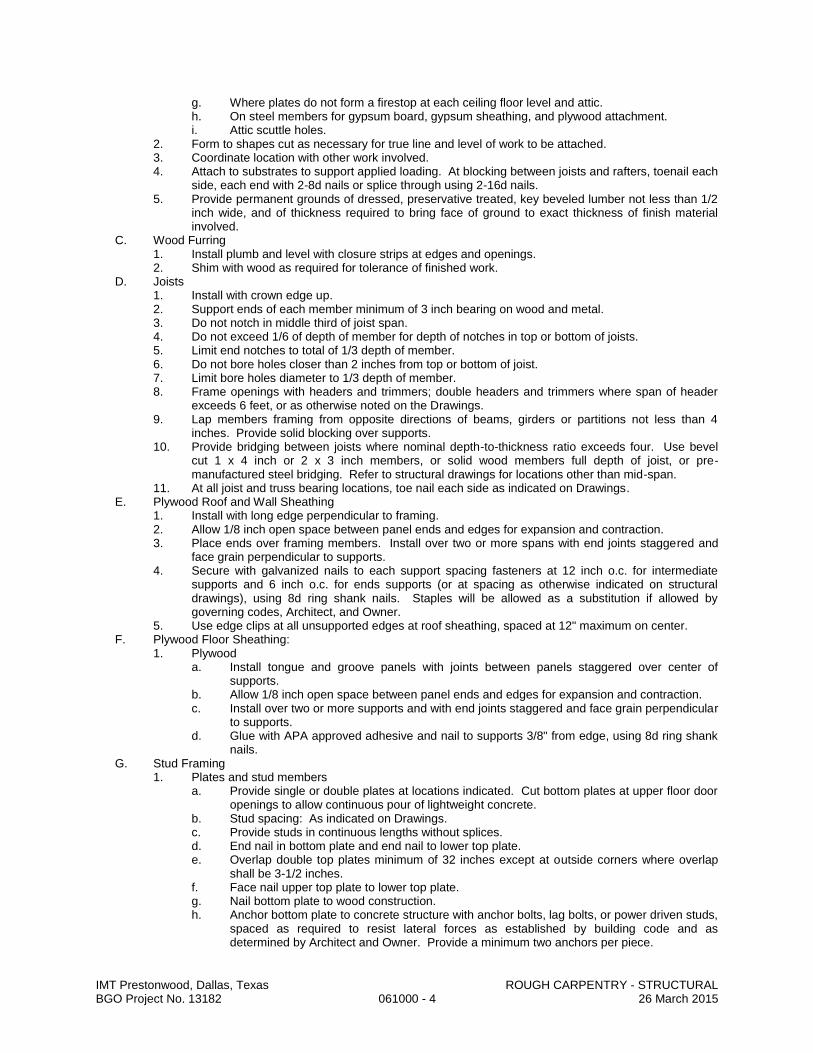
IMT Prestonwood, Dallas, Texas ROUGH CARPENTRY - STRUCTURAL BGO Project No. 13182 061000 - 4 26 March 2015
g. Where plates do not form a firestop at each ceiling floor level and attic. h. On steel members for gypsum board, gypsum sheathing, and plywood attachment. i. Attic scuttle holes.
2. Form to shapes cut as necessary for true line and level of work to be attached. 3. Coordinate location with other work involved. 4. Attach to substrates to support applied loading. At blocking between joists and rafters, toenail each
side, each end with 2-8d nails or splice through using 2-16d nails. 5. Provide permanent grounds of dressed, preservative treated, key beveled lumber not less than 1/2
inch wide, and of thickness required to bring face of ground to exact thickness of finish material involved.
C. Wood Furring 1. Install plumb and level with closure strips at edges and openings. 2. Shim with wood as required for tolerance of finished work.
D. Joists 1. Install with crown edge up. 2. Support ends of each member minimum of 3 inch bearing on wood and metal. 3. Do not notch in middle third of joist span. 4. Do not exceed 1/6 of depth of member for depth of notches in top or bottom of joists. 5. Limit end notches to total of 1/3 depth of member. 6. Do not bore holes closer than 2 inches from top or bottom of joist. 7. Limit bore holes diameter to 1/3 depth of member. 8. Frame openings with headers and trimmers; double headers and trimmers where span of header
exceeds 6 feet, or as otherwise noted on the Drawings. 9. Lap members framing from opposite directions of beams, girders or partitions not less than 4
inches. Provide solid blocking over supports. 10. Provide bridging between joists where nominal depth-to-thickness ratio exceeds four. Use bevel
cut 1 x 4 inch or 2 x 3 inch members, or solid wood members full depth of joist, or pre-manufactured steel bridging. Refer to structural drawings for locations other than mid-span.
11. At all joist and truss bearing locations, toe nail each side as indicated on Drawings. E. Plywood Roof and Wall Sheathing
1. Install with long edge perpendicular to framing. 2. Allow 1/8 inch open space between panel ends and edges for expansion and contraction. 3. Place ends over framing members. Install over two or more spans with end joints staggered and
face grain perpendicular to supports. 4. Secure with galvanized nails to each support spacing fasteners at 12 inch o.c. for intermediate
supports and 6 inch o.c. for ends supports (or at spacing as otherwise indicated on structural drawings), using 8d ring shank nails. Staples will be allowed as a substitution if allowed by governing codes, Architect, and Owner.
5. Use edge clips at all unsupported edges at roof sheathing, spaced at 12" maximum on center. F. Plywood Floor Sheathing:
1. Plywood a. Install tongue and groove panels with joints between panels staggered over center of
supports. b. Allow 1/8 inch open space between panel ends and edges for expansion and contraction. c. Install over two or more supports and with end joints staggered and face grain perpendicular
to supports. d. Glue with APA approved adhesive and nail to supports 3/8" from edge, using 8d ring shank
nails. G. Stud Framing
1. Plates and stud members a. Provide single or double plates at locations indicated. Cut bottom plates at upper floor door
openings to allow continuous pour of lightweight concrete. b. Stud spacing: As indicated on Drawings. c. Provide studs in continuous lengths without splices. d. End nail in bottom plate and end nail to lower top plate. e. Overlap double top plates minimum of 32 inches except at outside corners where overlap
shall be 3-1/2 inches. f. Face nail upper top plate to lower top plate. g. Nail bottom plate to wood construction. h. Anchor bottom plate to concrete structure with anchor bolts, lag bolts, or power driven studs,
spaced as required to resist lateral forces as established by building code and as determined by Architect and Owner. Provide a minimum two anchors per piece.

IMT Prestonwood, Dallas, Texas ROUGH CARPENTRY - STRUCTURAL BGO Project No. 13182 061000 - 5 26 March 2015
i. Triple studs at corners and partitions intersections. j. Anchor studs abutting masonry or concrete with 1/2 inch anchor bolts, maximum spacing of
2 feet o.c. k. Partitions parallel with joists: Locate joists directly below studs. l. Openings must be square, plumb, and level.
2. Headers a. Continuous headers, same width as studs, depth required to span widest opening. Provide
solid bearing. No shimming allowed. b. Toenail headers to studs and opening framing. c. Stagger joints in individual header members minimum of three stud spaces, allowing no
joints to occur over openings. d. Refer to structural drawings for additional information.
3. Blocking a. Wedge, align, and anchor blocking with countersunk bolts, washers and nuts, or nails. b. Locate blocking to facilitate installation of finishing materials, fixtures, specialty items, and
trim. 4. Place two beads of non-hardening sealant continuous under exterior and unit demising framed
walls on cementitious foundations. Refer to Section 07900 for material and installation. 5. Stud framing nailing schedule: Refer to Drawings.
H. Posts or Columns 1. Provide two surfaces on posts at right angles to each other for installation of interior finish
materials. 2. Erect posts straight, plumb with straight edge and level, and brace with tack boards at plate and sill. 3. Provide specified metal anchor and attachment devices.
I. Rafters 1. Notch to fit exterior wall plates and toenail to plates. 2. Double rafters at opening in roof framing to provide headers and trimmer, and support with metal
hangers. 3. At ridge, place rafters directly opposite each other and nail to ridge member or support with metal
hangers. 4. At valleys and hips, provide rafters of size as shown, or if not, rafters twice as thick as regular
rafters and 2 inches deeper. Bevel edge of jack rafters for full contact bearing against valley rafter. 5. Provide collar ties as shown, and if not, use 1 x 6 inch boards between every third pair of rafters,
located below ridge member, 1/3 of distance to ceiling joists. 6. At all rafter bearings, toe nail each side with 3-8d nails.
J. Beams and Girders 1. Install with crown edge up. 2. Provide minimum 3-1/2 inch bearing (unless indicated otherwise to be greater dimension) at ends
of each member. Tie together ends where jointed over supports if discontinuous. 3. Nail built-up beams or girders with two rows of 20d nails spaced maximum of 12" o.c., locating one
row near top edge and other near bottom edge of member. 4. Where members frame into pockets of masonry or concrete walls, allow 1/2 inch air space around
all sides and end. 5. At built-up beams, fasten together with one - 3/4" diameter bolt top and bottom at each end and
1/2" diameter bolt at 24" o.c. staggered top and bottom.
3.3 TOLERANCES A. Framing members: 1/4 inch maximum from true position. B. Surface flatness of floors/roofs: 1/4 inch in 10 feet maximum.
3.4 PROTECTION A. Protect products from moisture absorption and subsequent warping or deterioration until subsequent
construction can proceed.
END OF SECTION

IMT Prestonwood, Dallas, Texas ARCHITECTURAL ROUGH CARPENTRY BGO Project No. 13182 061100 - 1 26 March 2015
SECTION 061100
ARCHITECTURAL ROUGH CARPENTRY
PART 1 - GENERAL
1.1 RELATED DOCUMENTS A. Provisions established within General and Supplementary Conditions of the Contract, Division 01 -
General Requirements, and the Drawings are collectively applicable to this Section.
1.2 SECTION INCLUDES A. Exterior wood trim material. B. Fasteners. C. Related accessories.
1.3 DELIVERY, STORAGE AND HANDLING A. Deliver, store, handle, and protect products without damage in accordance with Section 016000. B. Store products above ground, on platforms or skids, and covered with appropriate coverings. Provide for
adequate air circulation. C. Do not store seasoned materials in damp or wet locations. D. Support products in such a way as to prevent warping and distortion.
PART 2 - PRODUCTS
2.1 MATERIALS A. Lumber
1. Grading rules: PS 20. 2. Dimensions: Lumber dimensions are nominal except for posts and timbers; actual dimensions
conform to industry standards established by the American Lumber Standards Committee and applicable rules writing agencies. Provide sizes as detailed.
3. Moisture content: 19% maximum moisture content after treatments for fire retardant and preservative treated woods.
4. Surfacing: Surface four sides (S4S), unless noted otherwise. 5. Species: Southern Yellow Pine or West Coast Douglas Fir, unless noted otherwise. 6. Uses, grades, and stress ratings: 7. Exterior wood trim, fascia boards: Species: Spruce-Pine-Fir (SPF) and Hem Fir (HF), pre-finished
as made by: a. Realtrim by Woodtone. b. Armor Coat Recon by Belco Forest Products.
B. Fasteners 1. Provide fasteners in sizes, spacings, and locations to suit applications and as indicated on the
Drawings. Galvanize for all exterior applications unless noted otherwise. 2. Bolts: FS FF-B-575, FF-B-584 or ASTM A307. 3. Nuts: FS FF-N-836. 4. Expansion shields, lag screws, and bolts: FS FF-B-561. 5. Toggle bolts: FS FF-B-588. 6. Wood screws: FS FF-S-111. 7. Nails and staples: FS FF-N-105. Provide only common wire nails or spikes of the sizes as shown
on the nailing schedule, except where otherwise indicated on the Drawings or as otherwise required by codes.
C. Adhesives: Waterproof, air cured type, cartridge dispenses, of strength to suit application.
2.2 WOOD TREATMENTS (SHOP PREPARED) A. Preservative Treated Wood (Pressure Impregnated)
1. Preservative treat sill plates and grounds in contact with concrete, roof curbs, cants and nailers for flashing, and elsewhere as noted or shown.
2. Use waterborne salt preservatives as follows: AWPB LP-2 above ground; AWPB LP 22 ground contact. Redry lumber to maximum 19% moisture content, stamp with AWPB "Dry". Redry plywood and particleboard to 15% maximum moisture content.

IMT Prestonwood, Dallas, Texas ARCHITECTURAL ROUGH CARPENTRY BGO Project No. 13182 061100 - 2 26 March 2015
PART 3 - EXECUTION
3.1 EXAMINATION A. Verify that surfaces and conditions are ready to receive work of this section. Notify Contractor of any
existing conditions which will adversely affect execution. Beginning of execution will constitute acceptance of existing conditions.
3.2 INSTALLATION A. General
1. Discard units of material with defects which might impair quality of work, and units which are too small to fabricate work with minimum joints or optimum joint arrangement.
2. Set carpentry work accurately to required levels and lines, with members plumb and true and accurately cut and fitted. Scribe and cope as required.
3. Securely attach carpentry work to substrates by anchoring and fastening as required by codes, the Drawings, as indicated herein, and as otherwise required to draw members into place and securely hold same unless otherwise indicated. Use washers under all bolt heads and nuts.
4. Select fasteners of size that will not penetrate members where opposite side will be exposed to view or will receive finish materials.
5. Make tight connections between members (except plywood) to develop full strength of members. 6. Install fasteners without splitting of wood. If wood is split, replace damaged member. 7. Predrill as necessary. 8. Comply with APA E30a requirements for plywood unless more stringent requirements for nailing
are indicated on the Drawings. 9. Install fastener types and at spacings recommended by NFPA National Design Specifications for
Stress Grade Lumber and Its Fastening - 1973 for lumber and APA Guide E30e for Plywood, unless more restrictive code requirements dictate tighter spacing or heavier fasteners, or unless otherwise indicated herein or on the Drawings.
10. Locate members as indicated on the drawings. Size, spacing or spans shall not be changed without specific approval of Architect. Take care to place proper grades and species of members where indicated in accordance with the lumber schedule herein.
3.3 TOLERANCES A. Framing members: 1/4 inch maximum from true position. B. Surface flatness of floors/roofs: 1/4 inch in 10 feet maximum.
3.4 PROTECTION A. Protect products from moisture absorption and subsequent warping or deterioration until subsequent
construction can proceed.
END OF SECTION
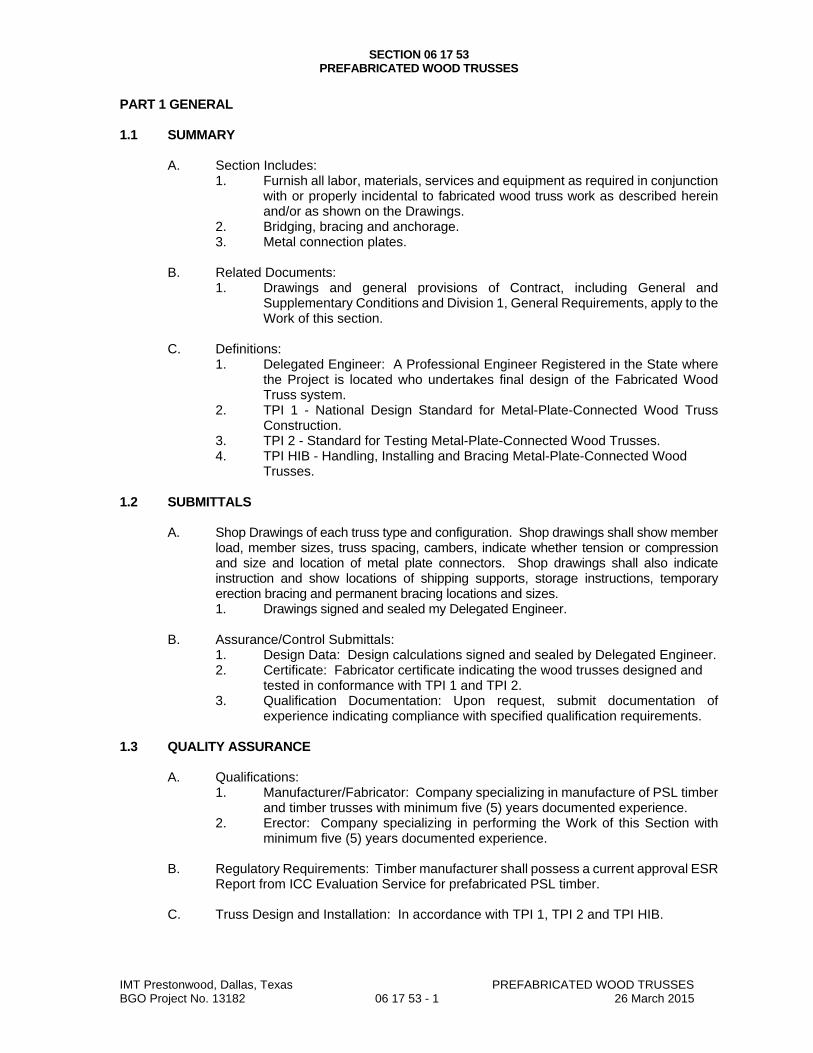
SECTION 06 17 53 PREFABRICATED WOOD TRUSSES
IMT Prestonwood, Dallas, Texas PREFABRICATED WOOD TRUSSES BGO Project No. 13182 06 17 53 - 1 26 March 2015
PART 1 GENERAL 1.1 SUMMARY
A. Section Includes: 1. Furnish all labor, materials, services and equipment as required in conjunction
with or properly incidental to fabricated wood truss work as described herein and/or as shown on the Drawings.
2. Bridging, bracing and anchorage. 3. Metal connection plates.
B. Related Documents:
1. Drawings and general provisions of Contract, including General and Supplementary Conditions and Division 1, General Requirements, apply to the Work of this section.
C. Definitions:
1. Delegated Engineer: A Professional Engineer Registered in the State where the Project is located who undertakes final design of the Fabricated Wood Truss system.
2. TPI 1 - National Design Standard for Metal-Plate-Connected Wood Truss Construction.
3. TPI 2 - Standard for Testing Metal-Plate-Connected Wood Trusses. 4. TPI HIB - Handling, Installing and Bracing Metal-Plate-Connected Wood
Trusses. 1.2 SUBMITTALS
A. Shop Drawings of each truss type and configuration. Shop drawings shall show member load, member sizes, truss spacing, cambers, indicate whether tension or compression and size and location of metal plate connectors. Shop drawings shall also indicate instruction and show locations of shipping supports, storage instructions, temporary erection bracing and permanent bracing locations and sizes. 1. Drawings signed and sealed my Delegated Engineer.
B. Assurance/Control Submittals:
1. Design Data: Design calculations signed and sealed by Delegated Engineer. 2. Certificate: Fabricator certificate indicating the wood trusses designed and
tested in conformance with TPI 1 and TPI 2. 3. Qualification Documentation: Upon request, submit documentation of
experience indicating compliance with specified qualification requirements. 1.3 QUALITY ASSURANCE
A. Qualifications: 1. Manufacturer/Fabricator: Company specializing in manufacture of PSL timber
and timber trusses with minimum five (5) years documented experience. 2. Erector: Company specializing in performing the Work of this Section with
minimum five (5) years documented experience.
B. Regulatory Requirements: Timber manufacturer shall possess a current approval ESR Report from ICC Evaluation Service for prefabricated PSL timber.
C. Truss Design and Installation: In accordance with TPI 1, TPI 2 and TPI HIB.
SECTION 06 17 53 PREFABRICATED WOOD TRUSSES
IMT Prestonwood, Dallas, Texas PREFABRICATED WOOD TRUSSES BGO Project No. 13182 06 17 53 - 1 26 March 2015
D. Single Source Responsibility: Obtain each type of member for trusses and prefabricated structural wood members specified in Division 6 - Shop-Fabricated Structural Wood, from one source by a single manufacturer.
1.4 PRODUCT HANDLING
A. Delivery and storage: 1. Exercise caution to maintain identification after bundles are broken. 2. Store in a manner to keep materials dry at all times. Protect against exposure to
weather and contact with damp or wet surfaces. Provide air circulation thru and around stored trusses.
1.5 SEQUENCING
A. Coordinate with other trades for proper and adequate provision of those trades for interface with work of this section.
PART 2 PRODUCTS 2.1 MATERIALS
A. Structural wood chord and web members shall be stress rated, kiln dried lumber in accordance with design requirements. 1. Factory mark each piece of lumber with type, grade, mill, and grading agency.
B. Connector plates shall be ASTM A 446, Grade A steel and shall be hot dip galvanized in
compliance with ASTM A 525, coating designation G-60.
C. Basis-of-Design Product: The design for Shop-Fabricated Wood Trusses is based on the product named. 1. Truss Joist: www.tji.com.
D. Product Options: Product options and substitutions. Subject to compliance with
requirements, provide either the named product or a comparable product by one of the following manufacturers: 1. Boise-Cascade: www.bosiecascade.com. 2. Georgia-Pacific: www.gp.com. 3. Louisiana-Pacific: www.louisianapacific.com.
2.2 TRUSS FABRICATION
A. Fabricate trusses to achieve structural requirements specified.
B. Brace wood timber trusses for support in accordance with TPI 1.
C. Cut truss members to accurate lengths, angles, and sizes to produce close fitting joints with wood-to-wood bearing in assembled units.
D. Fabricate metal connector plates to size, configuration, thickness, and anchorage
details required for types of joint design indicated.
E. Assemble truss members in design configuration indicated using jigs or other means to ensure uniformity and accuracy of assembly with close fitting joints. Position members to produce design camber indicated. Provide camber in accordance with TPI standards.
SECTION 06 17 53 PREFABRICATED WOOD TRUSSES
IMT Prestonwood, Dallas, Texas PREFABRICATED WOOD TRUSSES BGO Project No. 13182 06 17 53 - 1 26 March 2015
F. Connect truss members by means of metal connector plates accurately located and securely fastened to wood members by approved fasteners.
PART 3 EXECUTION 3.1 EXAMINATION
A. Examine areas and conditions under which work will be performed.
B. Verification of Conditions: Verify that field measurements, surfaces, substrates and conditions are as required, and ready to receive Work. 1. Verify supports and openings are ready to receive trusses. 2. Verify sufficient end bearing area. 3. Verify and coordinate placement of bearing support items.
C. Report in writing to Architect prevailing conditions that will adversely affect satisfactory
execution of the Work of this Section. Do not proceed with Work until unsatisfactory conditions have been corrected.
D. By beginning Work, Contractor accepts conditions and assumes responsibility for
correcting unsuitable conditions encountered at no additional cost to the Owner. 3.2 FABRICATION
A. Trusses shall be manufactured by a member in good standing of the Truss Plate Institute.
B. Erect trusses to the lines and elevations shown on the drawings in accordance with the manufacturer’s recommendations. Install permanent bracing of the sizes required at the locations specified on the shop drawings.
C. Do not field cut trusses.
3.3 CONSTRUCTION
A. Site Tolerances: 1. Truss Members: 1/2 inch maximum from true position.
3.4 QUALITY CONTROL
A. Contractor Quality Control Representative shall perform contractor quality control inspections 1. Inspect roof truss installation, type, configuration alignment, finish, blocking
and connection to structure. 2. Document preparatory, initial and follow-up inspection in Contractor’s Test and
Inspection Reports. 3. Test and Inspection Reports shall be available to Architect upon request.
B. Correct deficiencies in products and installation found not to be in compliance with
Contract Documents. END OF SECTION
IMT Prestonwood, Dallas, Texas FINISH CARPENTRY BGO Project No. 13182 062000 - 1 26 March 2015
SECTION 062000
FINISH CARPENTRY
PART 1 - GENERAL
1.1 SECTION INCLUDES A. Finish carpentry items. B. Wood casings and moldings. C. Hardware and attachment accessories.
1.2 SUBMITTALS A. See Section 013000 - Administrative Requirements for submittal procedures. B. Product Data: C. Shop Drawings: Indicate materials, component profiles, fastening methods, jointing details, accessories,
to a minimum scale of 1-1/2 inch to 1 ft.
1.3 QUALITY ASSURANCE A. Perform work in accordance with AWI Architectural Woodwork Quality Standards Illustrated, Custom grade
at clubhouse and Economy grade elsewhere. B. Fabricator Qualifications: Company specializing in fabricating the products specified in this section with
minimum three years of documented experience.
1.4 DELIVERY, STORAGE, AND HANDLING A. Protect work from moisture damage.
1.5 PROJECT CONDITIONS A. Sequence the installation to ensure utility connections are achieved in an orderly and expeditious manner. B. Coordinate the work with plumbing rough-in, electrical rough-in, and installation of associated and adjacent
components.
PART 2 - PRODUCTS
2.1 LUMBER MATERIALS A. Softwood Lumber: Southern Pine species, plain sawn, maximum moisture content of 6 percent; with
vertical grain, of quality suitable for transparent finish. B. Hardwood Lumber: Refer to Finish Legend for species, and cut, maximum moisture content of 6 percent;
with vertical grain, of quality suitable for transparent finish.
2.2 SHEET MATERIALS A. Softwood Plywood Not Exposed to View: Any face species, veneer core; PS 1 Grade A-B; glue type as
recommended for application. B. Softwood Plywood Exposed to View: Face species as indicated, plain sawn, medium density fiberboard
core; PS 1 Grade A-B; glue type as recommended for application. C. Hardwood Plywood: Face species as indicated in Finish Legend, cut as indicated, book matched, medium
density fiberboard core; glue type as recommended for application. D. Softwood Plywood: PS 1 Grade A-B; Veneer core; Southern Pine face species, plain sliced cut. E. Particleboard: ANSI A208.1; composed of wood chips, sawdust, or flakes of medium density, made with
waterproof resin binders; of grade to suit application; sanded faces.
2.3 FASTENERS A. Fasteners: Of size and type to suit application; brushed chrome finish in exposed locations.
2.4 ACCESSORIES A. Lumber for Shimming, Blocking: Softwood lumber of Southern Pine species. B. Primer: Alkyd primer sealer. C. Wood Filler: Solvent base, tinted to match surface finish color.
IMT Prestonwood, Dallas, Texas FINISH CARPENTRY BGO Project No. 13182 062000 - 2 26 March 2015
2.5 FABRICATION A. Shop assemble work for delivery to site, permitting passage through building openings. B. Fit exposed sheet material edges with 3/8 inch matching hardwood edging. Use one piece for full length
only. C. When necessary to cut and fit on site, provide materials with ample allowance for cutting. Provide trim for
scribing and site cutting.
2.6 SHOP FINISHING A. Sand work smooth and set exposed nails and screws. B. Apply wood filler in exposed nail and screw indentations. C. On items to receive transparent finishes, use wood filler that matches surrounding surfaces and is of type
recommended for the applicable finish. D. Finish work in accordance with AWI Architectural Woodwork Quality Standards Illustrated, Section 1500:
1. Transparent: Conversion varnish (formerly TR-4).
PART 3 - EXECUTION
3.1 EXAMINATION A. Verify adequacy of backing and support framing. B. Verify mechanical, electrical, and building items affecting work of this section are placed and ready to
receive this work.
3.2 INSTALLATION A. Set and secure materials and components in place, plumb and level. B. Carefully scribe work abutting other components, with maximum gaps of 1/32 inch. Do not use additional
overlay trim to conceal larger gaps.
3.3 TOLERANCES A. Maximum Variation from True Position: 1/16 inch. B. Maximum Offset from True Alignment with Abutting Materials: 1/32 inch.
3.4 SCHEDULE A. Interior of Units:
1. Window Sills: 5-1/4 inches wide soft wood with bullnose edge, prepare for paint finish. 2. Crown Moldings: MDF. 3. Bases, Casings, and Miscellaneous Trim: MDF; prepare for paint finish. 4. Aprons: 2-1/4 inch MDF; prepare for paint finish.
B. Interior of Clubhouse: 1. Stained grade hardwood, in profiles as indicated for base, crown, chair rails.
END OF SECTION
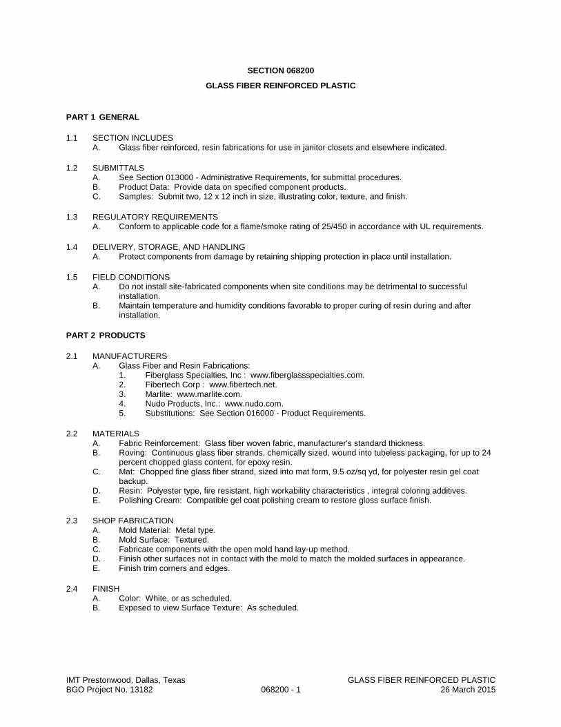
IMT Prestonwood, Dallas, Texas GLASS FIBER REINFORCED PLASTIC BGO Project No. 13182 068200 - 1 26 March 2015
SECTION 068200
GLASS FIBER REINFORCED PLASTIC
PART 1 GENERAL
1.1 SECTION INCLUDES A. Glass fiber reinforced, resin fabrications for use in janitor closets and elsewhere indicated.
1.2 SUBMITTALS A. See Section 013000 - Administrative Requirements, for submittal procedures. B. Product Data: Provide data on specified component products. C. Samples: Submit two, 12 x 12 inch in size, illustrating color, texture, and finish.
1.3 REGULATORY REQUIREMENTS A. Conform to applicable code for a flame/smoke rating of 25/450 in accordance with UL requirements.
1.4 DELIVERY, STORAGE, AND HANDLING A. Protect components from damage by retaining shipping protection in place until installation.
1.5 FIELD CONDITIONS A. Do not install site-fabricated components when site conditions may be detrimental to successful
installation. B. Maintain temperature and humidity conditions favorable to proper curing of resin during and after
installation.
PART 2 PRODUCTS
2.1 MANUFACTURERS A. Glass Fiber and Resin Fabrications:
1. Fiberglass Specialties, Inc : www.fiberglassspecialties.com. 2. Fibertech Corp : www.fibertech.net. 3. Marlite: www.marlite.com. 4. Nudo Products, Inc.: www.nudo.com. 5. Substitutions: See Section 016000 - Product Requirements.
2.2 MATERIALS A. Fabric Reinforcement: Glass fiber woven fabric, manufacturer's standard thickness. B. Roving: Continuous glass fiber strands, chemically sized, wound into tubeless packaging, for up to 24
percent chopped glass content, for epoxy resin. C. Mat: Chopped fine glass fiber strand, sized into mat form, 9.5 oz/sq yd, for polyester resin gel coat
backup. D. Resin: Polyester type, fire resistant, high workability characteristics , integral coloring additives. E. Polishing Cream: Compatible gel coat polishing cream to restore gloss surface finish.
2.3 SHOP FABRICATION A. Mold Material: Metal type. B. Mold Surface: Textured. C. Fabricate components with the open mold hand lay-up method. D. Finish other surfaces not in contact with the mold to match the molded surfaces in appearance. E. Finish trim corners and edges.
2.4 FINISH A. Color: White, or as scheduled. B. Exposed to view Surface Texture: As scheduled.

IMT Prestonwood, Dallas, Texas GLASS FIBER REINFORCED PLASTIC BGO Project No. 13182 068200 - 2 26 March 2015
PART 3 EXECUTION
3.1 EXAMINATION A. Verify that surfaces are ready to receive work and dimensions are as instructed by the fabricator.
3.2 INSTALLATION A. Install fabrications in accordance with shop drawings and fabricator's instructions.
3.3 TOLERANCES A. Maximum variation from true position: 1/4 inch. B. Maximum offset from true alignment: 1/8 inch.
3.4 CLEANING A. Clean components of foreign material without damaging finished surface. B. Hand rub smooth surfaces with polishing cream. C. Clean fabrications in accordance with fabricator's instructions.
3.5 PROTECTION A. Place protective structural covering over installed units.
END OF SECTION

IMT Prestonwood, Dallas, Texas SHEET WATERPROOFING BGO Project No. 13182 071300 - 1 26 March 2015
SECTION 071300
SHEET WATERPROOFING
PART 1 GENERAL
1.1 SECTION INCLUDES A. Sheet membrane waterproofing for use at:
1. Occupied areas of building where earth occurs on opposite side of wall. 2. Beneath concrete topping slabs at balconies, breezeways, and stairway access corridors. 3. Elevator pits. 4. Elsewhere as indicated on Drawings.
1.2 QUALITY ASSURANCE A. Perform Work in accordance with NRCA Roofing and Waterproofing Manual. B. Membrane Manufacturer Qualifications: Company specializing in waterproofing sheet membranes with
three years experience. C. Installer Qualifications: Company specializing in performing the work of this section with minimum
three years experience.
1.3 FIELD CONDITIONS A. Maintain ambient temperatures above 40 degrees F for 24 hours before and during application and
until liquid or mastic accessories have cured.
1.4 WARRANTY A. See Section 017800 - Closeout Submittals, for additional warranty requirements. B. Contractor shall correct defective Work within a five year period after Date of Substantial Completion;
remove and replace materials concealing waterproofing at no extra cost to Owner. C. Provide five year manufacturer warranty for waterproofing failing to resist penetration of water , except
where such failures are the result of structural failures of building. Hairline cracking of concrete due to temperature change or shrinkage is not considered a structural failure.
PART 2 PRODUCTS
2.1 WATERPROOFING APPLICATIONS A. Self-Adhered Modified Bituminous Sheet Waterproofing.
2.2 MEMBRANE MATERIALS A. Self-Adhered Modified Bituminous Membrane:
1. Thickness: 60 mil (0.060 inch). 2. Tensile Strength:
a. Film: 5000 pounds per square inch, minimum, measured according to ASTM D882 and at grip-separation rate of 2 inches per minute.
b. Membrane: 325 pounds per square inch, minimum, measured according to ASTM D412 Method A, using die C and at spindle-separation rate of 2 inches per minute.
3. Elongation at Break: 300 percent, minimum, measured according to ASTM D412. 4. Water Vapor Permeance: 0.05 perm, maximum, measured in accordance with ASTM
E96/E96M. 5. Low Temperature Flexibility: Unaffected when tested according to ASTM D1970 at minus 20
degrees F, 180 degree bend on 1 inch mandrel. 6. Peel Strength: 9 pounds per inch, minimum, when tested according to ASTM D903. 7. Lap Adhesion Strength: 4 pounds per inch, minimum, when tested according to ASTM D1876. 8. Puncture Resistance: 50 pounds, minimum, measured in accordance with ASTM E154. 9. Water Absorption: 0.1 percent increase in weight, maximum, measured in accordance with
ASTM D570, 24 hour immersion. 10. Hydrostatic Resistance: Resists the weight of 200 feet when tested according to ASTM D5385. 11. Adhesives, Sealants, Tapes, and Accessories: As recommended by membrane manufacturer. 12. Manufacturers:
a. Grace Construction Products ; Product Bituthene 3000: www.na.graceconstruction.com.
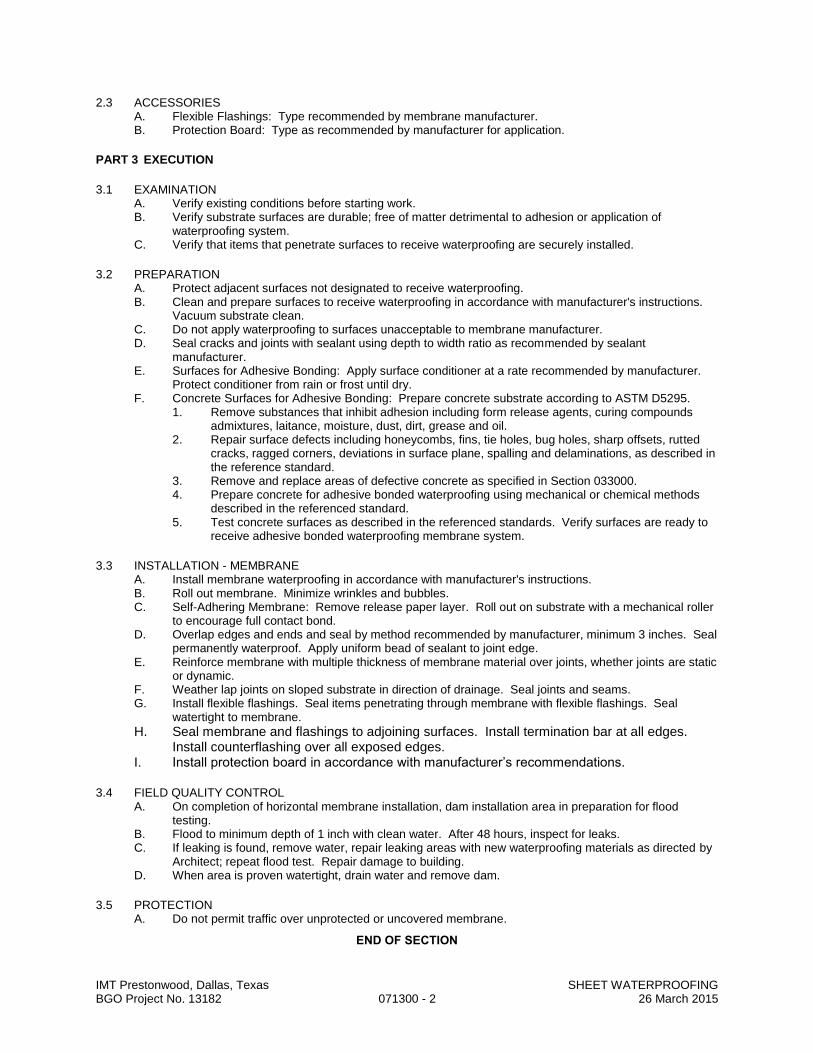
IMT Prestonwood, Dallas, Texas SHEET WATERPROOFING BGO Project No. 13182 071300 - 2 26 March 2015
2.3 ACCESSORIES A. Flexible Flashings: Type recommended by membrane manufacturer. B. Protection Board: Type as recommended by manufacturer for application.
PART 3 EXECUTION
3.1 EXAMINATION A. Verify existing conditions before starting work. B. Verify substrate surfaces are durable; free of matter detrimental to adhesion or application of
waterproofing system. C. Verify that items that penetrate surfaces to receive waterproofing are securely installed.
3.2 PREPARATION A. Protect adjacent surfaces not designated to receive waterproofing. B. Clean and prepare surfaces to receive waterproofing in accordance with manufacturer's instructions.
Vacuum substrate clean. C. Do not apply waterproofing to surfaces unacceptable to membrane manufacturer. D. Seal cracks and joints with sealant using depth to width ratio as recommended by sealant
manufacturer. E. Surfaces for Adhesive Bonding: Apply surface conditioner at a rate recommended by manufacturer.
Protect conditioner from rain or frost until dry. F. Concrete Surfaces for Adhesive Bonding: Prepare concrete substrate according to ASTM D5295.
1. Remove substances that inhibit adhesion including form release agents, curing compounds admixtures, laitance, moisture, dust, dirt, grease and oil.
2. Repair surface defects including honeycombs, fins, tie holes, bug holes, sharp offsets, rutted cracks, ragged corners, deviations in surface plane, spalling and delaminations, as described in the reference standard.
3. Remove and replace areas of defective concrete as specified in Section 033000. 4. Prepare concrete for adhesive bonded waterproofing using mechanical or chemical methods
described in the referenced standard. 5. Test concrete surfaces as described in the referenced standards. Verify surfaces are ready to
receive adhesive bonded waterproofing membrane system.
3.3 INSTALLATION - MEMBRANE A. Install membrane waterproofing in accordance with manufacturer's instructions. B. Roll out membrane. Minimize wrinkles and bubbles. C. Self-Adhering Membrane: Remove release paper layer. Roll out on substrate with a mechanical roller
to encourage full contact bond. D. Overlap edges and ends and seal by method recommended by manufacturer, minimum 3 inches. Seal
permanently waterproof. Apply uniform bead of sealant to joint edge. E. Reinforce membrane with multiple thickness of membrane material over joints, whether joints are static
or dynamic. F. Weather lap joints on sloped substrate in direction of drainage. Seal joints and seams. G. Install flexible flashings. Seal items penetrating through membrane with flexible flashings. Seal
watertight to membrane.
H. Seal membrane and flashings to adjoining surfaces. Install termination bar at all edges. Install counterflashing over all exposed edges.
I. Install protection board in accordance with manufacturer’s recommendations.
3.4 FIELD QUALITY CONTROL A. On completion of horizontal membrane installation, dam installation area in preparation for flood
testing. B. Flood to minimum depth of 1 inch with clean water. After 48 hours, inspect for leaks. C. If leaking is found, remove water, repair leaking areas with new waterproofing materials as directed by
Architect; repeat flood test. Repair damage to building. D. When area is proven watertight, drain water and remove dam.
3.5 PROTECTION A. Do not permit traffic over unprotected or uncovered membrane.
END OF SECTION
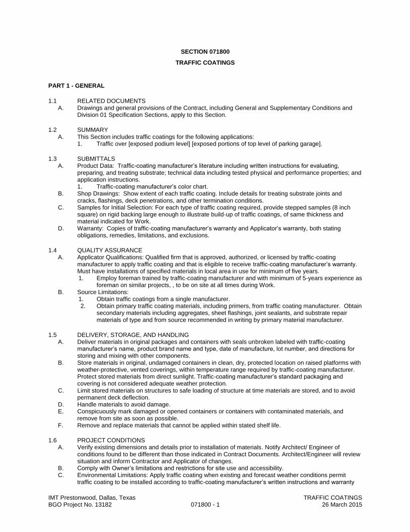
IMT Prestonwood, Dallas, Texas TRAFFIC COATINGS BGO Project No. 13182 071800 - 1 26 March 2015
SECTION 071800
TRAFFIC COATINGS
PART 1 - GENERAL
1.1 RELATED DOCUMENTS A. Drawings and general provisions of the Contract, including General and Supplementary Conditions and
Division 01 Specification Sections, apply to this Section.
1.2 SUMMARY A. This Section includes traffic coatings for the following applications:
1. Traffic over [exposed podium level] [exposed portions of top level of parking garage].
1.3 SUBMITTALS A. Product Data: Traffic-coating manufacturer’s literature including written instructions for evaluating,
preparing, and treating substrate; technical data including tested physical and performance properties; and application instructions. 1. Traffic-coating manufacturer’s color chart.
B. Shop Drawings: Show extent of each traffic coating. Include details for treating substrate joints and cracks, flashings, deck penetrations, and other termination conditions.
C. Samples for Initial Selection: For each type of traffic coating required, provide stepped samples (8 inch square) on rigid backing large enough to illustrate build-up of traffic coatings, of same thickness and material indicated for Work.
D. Warranty: Copies of traffic-coating manufacturer’s warranty and Applicator’s warranty, both stating obligations, remedies, limitations, and exclusions.
1.4 QUALITY ASSURANCE A. Applicator Qualifications: Qualified firm that is approved, authorized, or licensed by traffic-coating
manufacturer to apply traffic coating and that is eligible to receive traffic-coating manufacturer’s warranty. Must have installations of specified materials in local area in use for minimum of five years. 1. Employ foreman trained by traffic-coating manufacturer and with minimum of 5-years experience as
foreman on similar projects, , to be on site at all times during Work. B. Source Limitations:
1. Obtain traffic coatings from a single manufacturer. 2. Obtain primary traffic coating materials, including primers, from traffic coating manufacturer. Obtain
secondary materials including aggregates, sheet flashings, joint sealants, and substrate repair materials of type and from source recommended in writing by primary material manufacturer.
1.5 DELIVERY, STORAGE, AND HANDLING A. Deliver materials in original packages and containers with seals unbroken labeled with traffic-coating
manufacturer’s name, product brand name and type, date of manufacture, lot number, and directions for storing and mixing with other components.
B. Store materials in original, undamaged containers in clean, dry, protected location on raised platforms with weather-protective, vented coverings, within temperature range required by traffic-coating manufacturer. Protect stored materials from direct sunlight. Traffic-coating manufacturer’s standard packaging and covering is not considered adequate weather protection.
C. Limit stored materials on structures to safe loading of structure at time materials are stored, and to avoid permanent deck deflection.
D. Handle materials to avoid damage. E. Conspicuously mark damaged or opened containers or containers with contaminated materials, and
remove from site as soon as possible. F. Remove and replace materials that cannot be applied within stated shelf life.
1.6 PROJECT CONDITIONS A. Verify existing dimensions and details prior to installation of materials. Notify Architect/ Engineer of
conditions found to be different than those indicated in Contract Documents. Architect/Engineer will review situation and inform Contractor and Applicator of changes.
B. Comply with Owner’s limitations and restrictions for site use and accessibility. C. Environmental Limitations: Apply traffic coating when existing and forecast weather conditions permit
traffic coating to be installed according to traffic-coating manufacturer’s written instructions and warranty

IMT Prestonwood, Dallas, Texas TRAFFIC COATINGS BGO Project No. 13182 071800 - 2 26 March 2015
requirements. Do not apply traffic coating under following conditions, unless otherwise recommended by traffic-coating manufacturer and approved by Architect/Engineer. 1. Do not apply when substrate temperature is below 50 degrees F or less than 5 degrees F above
dew point, or outside of range recommended by traffic-coating manufacturer. 2. Do not apply when ambient temperature is below 40 degrees F or outside of range recommended
by traffic-coating manufacturer. 3. Do not apply to damp or wet substrate; when relative humidity exceeds 85 percent; in snow, rain,
fog, or mist; or when snow, rain, fog, or mist is forecast during application or curing period. Apply only to frost-free substrate.
D. Install materials in strict accordance with safety requirements required by traffic-coating manufacturer, Material Safety Data Sheets, and local, state, and federal rules and regulations.
E. Maintain adequate ventilation during preparation and application of traffic-coating materials. Notify Owner’s Representative at least 1 week in advance of Work with materials with noxious vapors. Review application schedule and venting precautions with Owner’s Representative prior to beginning application.
F. Do not install traffic coating until items that will penetrate membrane have been installed.
1.7 WARRANTY A. Manufacturer’s Warranty:
1. Written warranty, signed by traffic-coating manufacturer, including a. Repair or replace traffic coating that does not comply with requirements; that does not
remain watertight; that fails in adhesion, cohesion, or general durability; that experiences abrasion or tearing failure not due to misuse; that experiences surface crazing, fading or chalking; or that deteriorates in manner not clearly specified by submitted traffic-coating manufacturer’s data as inherent quality of material for application indicated. Warranty does not include deterioration or failure of traffic coating due to failure of substrate prepared according to requirements, formation of new substrate cracks exceeding 1/16 inch in width, fire, vandalism, or snowplow abuse.
b. Provide access to warranty repair and replacement areas. 2. Warranty Period: 10 years after Substantial Completion date.
PART 2 - PRODUCTS
2.1 MATERIALS A. Traffic Coatings: Complying with ASTM C 957. B. Material Compatibility: Provide primers; base, intermediate, and topcoats; and miscellaneous materials
that are compatible with one another and with substrate under conditions of service and application, as demonstrated by manufacturer based on testing and field experience.
C. Source Limitations: Obtain materials through one source from single traffic-coating manufacturer. Provide materials not available from traffic-coating manufacturer from sources approved by traffic-coating manufacturer. Provide new materials.
D. VOC Content: Provide traffic coatings[ and pavement marking paints], for use inside the weatherproofing system, with VOC content of 150 g/L when calculated according to 40 CFR 59, Subpart D (EPA Method 24).
2.2 TRAFFIC COATING A. Available Products: Subject to compliance with requirements, products that may be incorporated into the
Work include, but are not limited to, the following: 1. Heavy-duty pedestrian or medium-duty vehicular system.
a. Iso-Flex 750U MVT Deck Coating System, manufactured by LymTal International, Inc., Lake Orion, MI, consisting 25 dry mils of base coat, 15 dry mils of wear course, and 6 to 8 pounds of sand per 100 square foot.
b. Auto-Gard Vehicular Traffic-Bearing Waterproofing, manufactured by Neogard, Dallas, TX, consisting of 20 dry mils of base coat, 20 dry mils of wearing surface coat, and 10 to 15 pounds of aggregate per 100 square feet.
c. Sonoguard Light-to-Medium-Duty Vehicular System, manufactured by Sonneborn, consisting of 20 dry mils of base coat, 20 dry mils of finish coat, and 10 to 25 pounds of aggregate per 100 square feet.
2. Primer: Traffic-coating manufacturer’s standard, factory-formulated primer recommended for substrate under conditions of service and application.
3. Top Coat Color: Selected from manufacturers full range. 4. Aggregate: Uniformly graded, washed silicon carbide sand of particle sizes, shape, and minimum
hardness recommended in writing by traffic coating manufacturer.
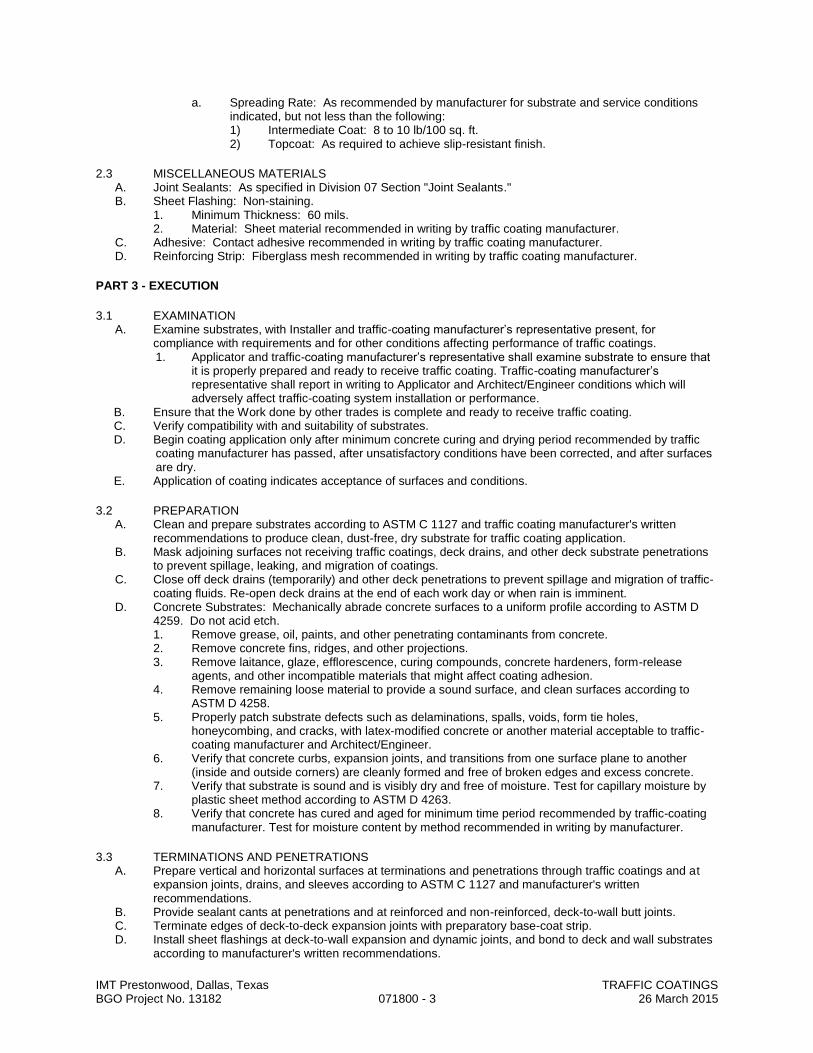
IMT Prestonwood, Dallas, Texas TRAFFIC COATINGS BGO Project No. 13182 071800 - 3 26 March 2015
a. Spreading Rate: As recommended by manufacturer for substrate and service conditions indicated, but not less than the following: 1) Intermediate Coat: 8 to 10 lb/100 sq. ft. 2) Topcoat: As required to achieve slip-resistant finish.
2.3 MISCELLANEOUS MATERIALS A. Joint Sealants: As specified in Division 07 Section "Joint Sealants." B. Sheet Flashing: Non-staining.
1. Minimum Thickness: 60 mils. 2. Material: Sheet material recommended in writing by traffic coating manufacturer.
C. Adhesive: Contact adhesive recommended in writing by traffic coating manufacturer. D. Reinforcing Strip: Fiberglass mesh recommended in writing by traffic coating manufacturer.
PART 3 - EXECUTION
3.1 EXAMINATION A. Examine substrates, with Installer and traffic-coating manufacturer’s representative present, for
compliance with requirements and for other conditions affecting performance of traffic coatings. 1. Applicator and traffic-coating manufacturer’s representative shall examine substrate to ensure that
it is properly prepared and ready to receive traffic coating. Traffic-coating manufacturer’s representative shall report in writing to Applicator and Architect/Engineer conditions which will adversely affect traffic-coating system installation or performance.
B. Ensure that the Work done by other trades is complete and ready to receive traffic coating. C. Verify compatibility with and suitability of substrates. D. Begin coating application only after minimum concrete curing and drying period recommended by traffic
coating manufacturer has passed, after unsatisfactory conditions have been corrected, and after surfaces are dry.
E. Application of coating indicates acceptance of surfaces and conditions.
3.2 PREPARATION A. Clean and prepare substrates according to ASTM C 1127 and traffic coating manufacturer's written
recommendations to produce clean, dust-free, dry substrate for traffic coating application. B. Mask adjoining surfaces not receiving traffic coatings, deck drains, and other deck substrate penetrations
to prevent spillage, leaking, and migration of coatings. C. Close off deck drains (temporarily) and other deck penetrations to prevent spillage and migration of traffic-
coating fluids. Re-open deck drains at the end of each work day or when rain is imminent. D. Concrete Substrates: Mechanically abrade concrete surfaces to a uniform profile according to ASTM D
4259. Do not acid etch. 1. Remove grease, oil, paints, and other penetrating contaminants from concrete. 2. Remove concrete fins, ridges, and other projections. 3. Remove laitance, glaze, efflorescence, curing compounds, concrete hardeners, form-release
agents, and other incompatible materials that might affect coating adhesion. 4. Remove remaining loose material to provide a sound surface, and clean surfaces according to
ASTM D 4258. 5. Properly patch substrate defects such as delaminations, spalls, voids, form tie holes,
honeycombing, and cracks, with latex-modified concrete or another material acceptable to traffic-coating manufacturer and Architect/Engineer.
6. Verify that concrete curbs, expansion joints, and transitions from one surface plane to another (inside and outside corners) are cleanly formed and free of broken edges and excess concrete.
7. Verify that substrate is sound and is visibly dry and free of moisture. Test for capillary moisture by plastic sheet method according to ASTM D 4263.
8. Verify that concrete has cured and aged for minimum time period recommended by traffic-coating manufacturer. Test for moisture content by method recommended in writing by manufacturer.
3.3 TERMINATIONS AND PENETRATIONS A. Prepare vertical and horizontal surfaces at terminations and penetrations through traffic coatings and at
expansion joints, drains, and sleeves according to ASTM C 1127 and manufacturer's written recommendations.
B. Provide sealant cants at penetrations and at reinforced and non-reinforced, deck-to-wall butt joints. C. Terminate edges of deck-to-deck expansion joints with preparatory base-coat strip. D. Install sheet flashings at deck-to-wall expansion and dynamic joints, and bond to deck and wall substrates
according to manufacturer's written recommendations.

IMT Prestonwood, Dallas, Texas TRAFFIC COATINGS BGO Project No. 13182 071800 - 4 26 March 2015
3.4 JOINT AND CRACK TREATMENT A. Prepare, treat, rout, and fill joints and cracks in substrates according to ASTM C 1127 and manufacturer's
written recommendations. Before coating surfaces, remove dust and dirt from joints and cracks according to ASTM D 4258. 1. Comply with recommendations in ASTM C 1193 for joint-sealant installation.
3.5 TRAFFIC COATING APPLICATION A. Apply traffic coating material according to ASTM C 1127 and manufacturer's written recommendations.
1. Start traffic coating application in presence of manufacturer's technical representative. 2. Verify that wet film thickness of each component coat complies with requirements every 100 sq. ft.. 3. Install joint reinforcement, centered on joints and horizontal edges of sheet-metal flashing and
pans, in detail coat. 4. Wipe detail coat to remove dust and contamination. 5. Apply traffic coatings to prepared wall terminations and vertical surfaces to height indicated, and
omit aggregate on vertical surfaces. 6. Apply each coat in one uniform application, broadcast aggregate if required, and backroll for even
coverage. Allow each coat to cure before apply next coat. Sweep or vacuum off excess aggregate. 7. Apply at least 4 inches up sides of columns, walls, and other vertical surfaces, and up curb faces
and across top curb surfaces. 8. Omit aggregate on vertical surfaces. 9. If pinholes occur in base coat, apply additional base coat material using flat squeegee or other tool
approved by traffic-coating manufacturer, to fill holes before proceeding with subsequent coats. 10. Prevent contamination or damage during application and curing. 11. Cure traffic coatings according to manufacturer's written recommendations. Prevent contamination
and damage during application and curing stages.
3.6 PROTECTING AND CLEANING A. Protect traffic coatings from damage and wear during remainder of construction period. B. Clean spillage from adjacent construction using cleaning agents and procedures recommended by
manufacturer of affected construction. C. Replace Work or materials damaged beyond repair, in opinion of Architect/Engineer, at no cost to Owner.
END OF SECTION

IMT Prestonwood, Dallas, Texas THERMAL INSULATION BGO Project No. 13182 072100 - 1 26 March 2015
SECTION 072100
THERMAL INSULATION
PART 1 GENERAL
1.1 SECTION INCLUDES A. Batt insulation in exterior wall and ceiling construction.
1.2 SUBMITTALS A. See Section 013000 - Administrative Requirements, for submittal procedures. B. Product Data: Provide data on product characteristics, performance criteria, and product limitations. C. Manufacturer's Installation Instructions: Include information on special environmental conditions
required for installation and installation techniques. D. Manufacturer's Certificate: Certify that products meet or exceed specified requirements.
1.3 FIELD CONDITIONS A. Do not install insulation adhesives when temperature or weather conditions are detrimental to
successful installation.
PART 2 PRODUCTS
2.1 MANUFACTURERS A. Insulation:
1. Owens Corning. 2. Certainteed. 3. USG. 4. Johns Manville. 5. Substitutions: See Section 016000 - Product Requirements.
2.2 APPLICATIONS A. Insulation in Wood Framed Walls: Batt insulation with no vapor retarder.
2.3 BATT INSULATION MATERIALS A. Glass Fiber Batt Insulation: Flexible preformed batt or blanket, complying with ASTM C665; friction fit.
1. Flame Spread Index: 25 or less, when tested in accordance with ASTM E84. 2. Smoke Developed Index: 450 or less, when tested in accordance with ASTM E84. 3. Combustibility: Non-combustible, when tested in accordance with ASTM E136 , except for
facing, if any. 4. Formaldehyde Content: Zero. 5. Thermal Resistance: As indicated on Drawings, but not less than
a. R-38 at attics b. R-19 at ceilings over un-conditioned areas, c. R-13 at exterior walls d. R-11 in floor/ceiling assemblies between units e. R-11 for acoustical applications at party walls, walls with common areas, and all walls
within living units. 6. Facing:
a. Unfaced (typical) 7. Manufacturers:
a. CertainTeed Corporation: www.certainteed.com. b. Johns Manville Corporation: www.jm.com. c. Knauf Insulation GmbH: www.knaufinsulation.us. d. Owens Corning Corp: www.owenscorning.com.
8. Substitutions: See Section 016000 - Product Requirements.

IMT Prestonwood, Dallas, Texas THERMAL INSULATION BGO Project No. 13182 072100 - 2 26 March 2015
PART 3 EXECUTION
3.1 EXAMINATION A. Verify that substrate, adjacent materials, and insulation materials are dry and that substrates are ready
to receive insulation and adhesive. B. Verify substrate surfaces are flat, free of honeycomb, fins, irregularities, or materials or substances that
may impede adhesive bond.
3.2 BATT INSTALLATION A. Install insulation and vapor retarder in accordance with manufacturer's instructions. B. Install in exterior wall and roof spaces without gaps or voids. Do not compress insulation. C. Trim insulation neatly to fit spaces. Insulate miscellaneous gaps and voids. D. Fit insulation tightly in cavities and tightly to exterior side of mechanical and electrical services within
the plane of the insulation. E. Coordinate work of this section with construction of air barrier seal specified in Section 072500.
3.3 PROTECTION A. Do not permit installed insulation to be damaged prior to its concealment.
END OF SECTION

IMT Prestonwood, Dallas, Texas BLOWN INSULATION BGO Project No. 13182 072126 - 1 26 March 2015
SECTION 072126
BLOWN INSULATION
PART 1 GENERAL
1.1 SECTION INCLUDES A. Loose insulation pneumatically placed and poured into joist spaces through access holes.
1.2 SYSTEM DESCRIPTION A. Materials of This Section: Provide continuity of thermal barrier at building enclosure elements, in
conjunction with Section 072100.
1.3 SUBMITTALS A. See Section 013000 - Administrative Requirements, for submittal procedures. B. Product Data: Provide data on product characteristics, performance criteria, limitations . C. Manufacturer's Installation Instructions: Indicate procedure for preparation and installation. D. Certificates: Certify that products of this section meet or exceed specified requirements.
PART 2 PRODUCTS
2.1 MANUFACTURERS A. Blown Insulation:
1. CertainTeed Corporation : www.certainteed.com. 2. GreenFiber : www.greenfiber.com 3. Johns Manville Corporation : www.jm.com. 4. Substitutions: See Section 016000 - Product Requirements.
2.2 MATERIALS A. Loose Fill Insulation: Provide one of the following:
1. ASTM C739, cellulose fiber type, nodulated for pour and bulk for pneumatic placement. 2. ASTM C 764, glass fiber type, nodulated for pour and bulk for pneumatic placement.
B. Thermal Conductivity: 0.27 BTU in/(hr sq ft deg F). C. Installed Thickness: As indicated on drawings, but not less than R-38 in attic spaces. Fully fill truss
cavities where indicated. D. Ventilation Baffles: Formed plastic.
PART 3 EXECUTION
3.1 EXAMINATION
A. Verify that substrate, adjacent materials, and insulation are dry and ready to receive insulation.
B. Verify that light fixtures have thermal cut-out device to restrict over-heating in soffit or ceiling spaces.
C. Verify spaces are unobstructed to allow placement of insulation.
3.2 INSTALLATION
A. Install insulation and ventilation baffle in accordance with ASTM C1015 and manufacturer's instructions.
B. Place insulation pneumatically to completely fill stud, joist, and rafter spaces .
C. Place insulation against baffles. Do not impede natural attic ventilation to soffit.
D. Place against and behind mechanical and electrical services within the plane of insulation.
E. Completely fill intended spaces. Leave no gaps or voids.
F. Repair and reseal insulation access ports. Refinish to match disturbed work.
END OF SECTION
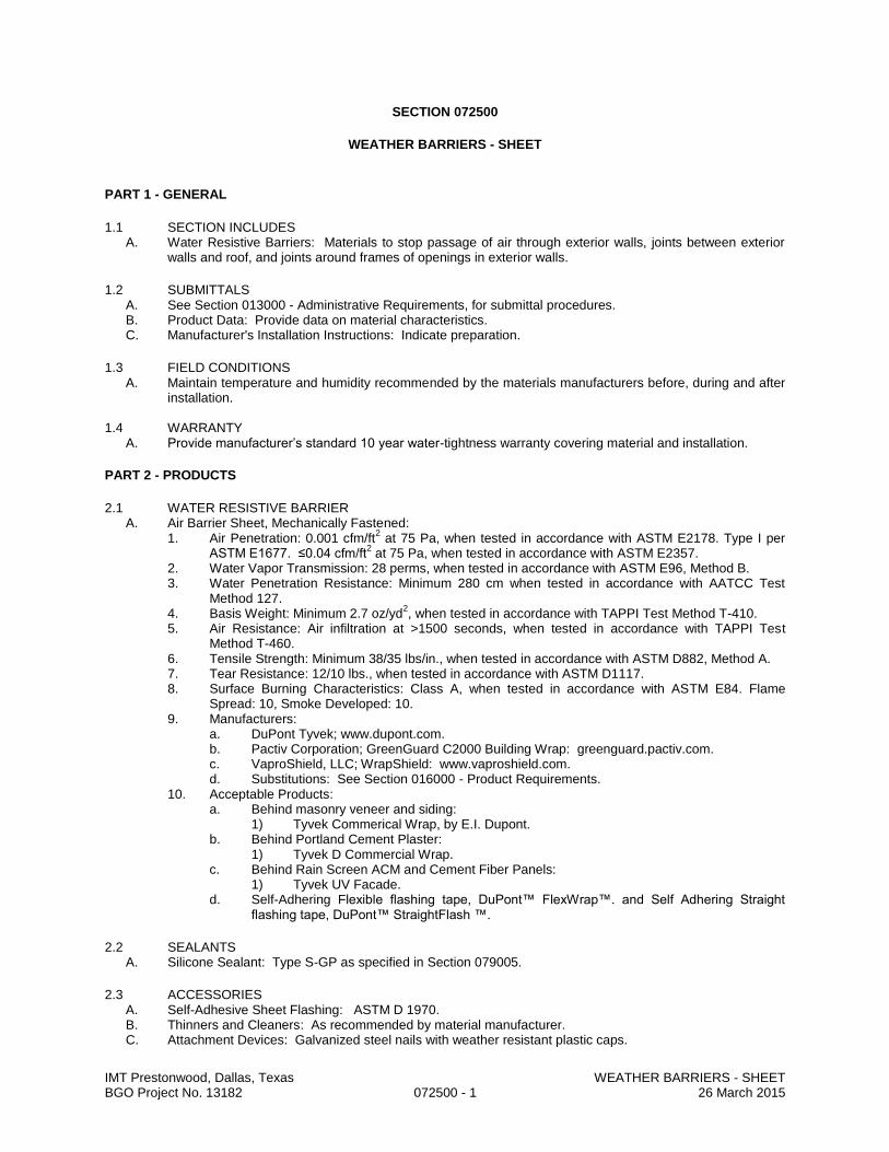
IMT Prestonwood, Dallas, Texas WEATHER BARRIERS - SHEET BGO Project No. 13182 072500 - 1 26 March 2015
SECTION 072500
WEATHER BARRIERS - SHEET
PART 1 - GENERAL
1.1 SECTION INCLUDES A. Water Resistive Barriers: Materials to stop passage of air through exterior walls, joints between exterior
walls and roof, and joints around frames of openings in exterior walls.
1.2 SUBMITTALS A. See Section 013000 - Administrative Requirements, for submittal procedures. B. Product Data: Provide data on material characteristics. C. Manufacturer's Installation Instructions: Indicate preparation.
1.3 FIELD CONDITIONS A. Maintain temperature and humidity recommended by the materials manufacturers before, during and after
installation.
1.4 WARRANTY A. Provide manufacturer’s standard 10 year water-tightness warranty covering material and installation.
PART 2 - PRODUCTS
2.1 WATER RESISTIVE BARRIER A. Air Barrier Sheet, Mechanically Fastened:
1. Air Penetration: 0.001 cfm/ft2 at 75 Pa, when tested in accordance with ASTM E2178. Type I per
ASTM E1677. ≤0.04 cfm/ft2 at 75 Pa, when tested in accordance with ASTM E2357.
2. Water Vapor Transmission: 28 perms, when tested in accordance with ASTM E96, Method B. 3. Water Penetration Resistance: Minimum 280 cm when tested in accordance with AATCC Test
Method 127. 4. Basis Weight: Minimum 2.7 oz/yd
2, when tested in accordance with TAPPI Test Method T-410.
5. Air Resistance: Air infiltration at >1500 seconds, when tested in accordance with TAPPI Test Method T-460.
6. Tensile Strength: Minimum 38/35 lbs/in., when tested in accordance with ASTM D882, Method A. 7. Tear Resistance: 12/10 lbs., when tested in accordance with ASTM D1117. 8. Surface Burning Characteristics: Class A, when tested in accordance with ASTM E84. Flame
Spread: 10, Smoke Developed: 10. 9. Manufacturers:
a. DuPont Tyvek; www.dupont.com. b. Pactiv Corporation; GreenGuard C2000 Building Wrap: greenguard.pactiv.com. c. VaproShield, LLC; WrapShield: www.vaproshield.com. d. Substitutions: See Section 016000 - Product Requirements.
10. Acceptable Products: a. Behind masonry veneer and siding:
1) Tyvek Commerical Wrap, by E.I. Dupont. b. Behind Portland Cement Plaster:
1) Tyvek D Commercial Wrap. c. Behind Rain Screen ACM and Cement Fiber Panels:
1) Tyvek UV Facade. d. Self-Adhering Flexible flashing tape, DuPont™ FlexWrap™. and Self Adhering Straight
flashing tape, DuPont™ StraightFlash ™.
2.2 SEALANTS A. Silicone Sealant: Type S-GP as specified in Section 079005.
2.3 ACCESSORIES A. Self-Adhesive Sheet Flashing: ASTM D 1970. B. Thinners and Cleaners: As recommended by material manufacturer. C. Attachment Devices: Galvanized steel nails with weather resistant plastic caps.

IMT Prestonwood, Dallas, Texas WEATHER BARRIERS - SHEET BGO Project No. 13182 072500 - 2 26 March 2015
PART 3 - EXECUTION
3.1 EXAMINATION A. Verify that surfaces and conditions are ready to accept the work of this section.
3.2 PREPARATION A. Remove projections, protruding fasteners, and loose or foreign matter that might interfere with proper
installation.
3.3 INSTALLATION A. Install materials in accordance with manufacturer's instructions. B. Water-Resistive/Air Barriers: Install continuous barrier over surfaces indicated, with sheets lapped to shed
water but with seams not sealed. C. Mechanically Fastened Sheets - On Exterior:
1. Install sheets shingle-fashion to shed water, with seams generally horizontal. 2. Overlap seams as recommended by manufacturer but at least 6 inches. 3. Overlap at outside and inside corners as recommended by manufacturer but at least 12 inches. 4. Attach to framed construction with fasteners extending through sheathing into framing. Space
fasteners at 12 to 18 inches on center along each framing member supporting sheathing. 5. For applications specified to be air-tight, seal seams, laps, penetrations, tears, and cuts with self-
adhesive tape; use only large-headed, gasketed fasteners recommended by the manufacturer. 6. Install air barrier UNDER jamb flashings. 7. Install head flashings under weather barrier. 8. At openings to be filled with frames having nailing flanges, wrap excess sheet into opening; at
head, seal sheet over flange and flashing. D. Openings and Penetrations in Exterior Weather Barriers:
1. Install self-adhesive flashing over sills, covering entire sill frame member, extending at least 5 inches onto weather barrier and at least 6 inches up jambs; mechanically fasten stretched edges.
2. At openings to be filled with frames having nailing flanges, seal head and jamb flanges using a continuous bead of sealant compressed by flange and cover flanges with self-adhesive flashing at least 4 inches wide; do not seal sill flange.
3. At openings to be filled with non-flanged frames, seal weather barrier to all sides of opening framing, using self-adhesive flashing at least 9 inches wide, covering entire depth of framing.
4. At head of openings, install self-adhesive flashing under weather barrier extending at least 2 inches beyond face of jambs; seal weather barrier to flashing.
5. At interior face of openings, seal gap between window/door frame and rough framing, using joint sealant over backer rod.
6. Service and Other Penetrations: Form self-adhesive flashing around penetrating item and seal to weather barrier surface.
3.4 FIELD QUALITY CONTROL A. Do not cover installed weather barriers until required inspections have been completed. B. Obtain approval of installation procedures by the weather barrier manufacturer based on a mock-up
installed in place, prior to proceeding with remainder of installation. C. Provide inspections as required by weather barrier manufacturer as required to secure warranty indicated.
3.5 PROTECTION A. Do not leave materials exposed to weather longer than recommended by manufacturer.
END OF SECTION
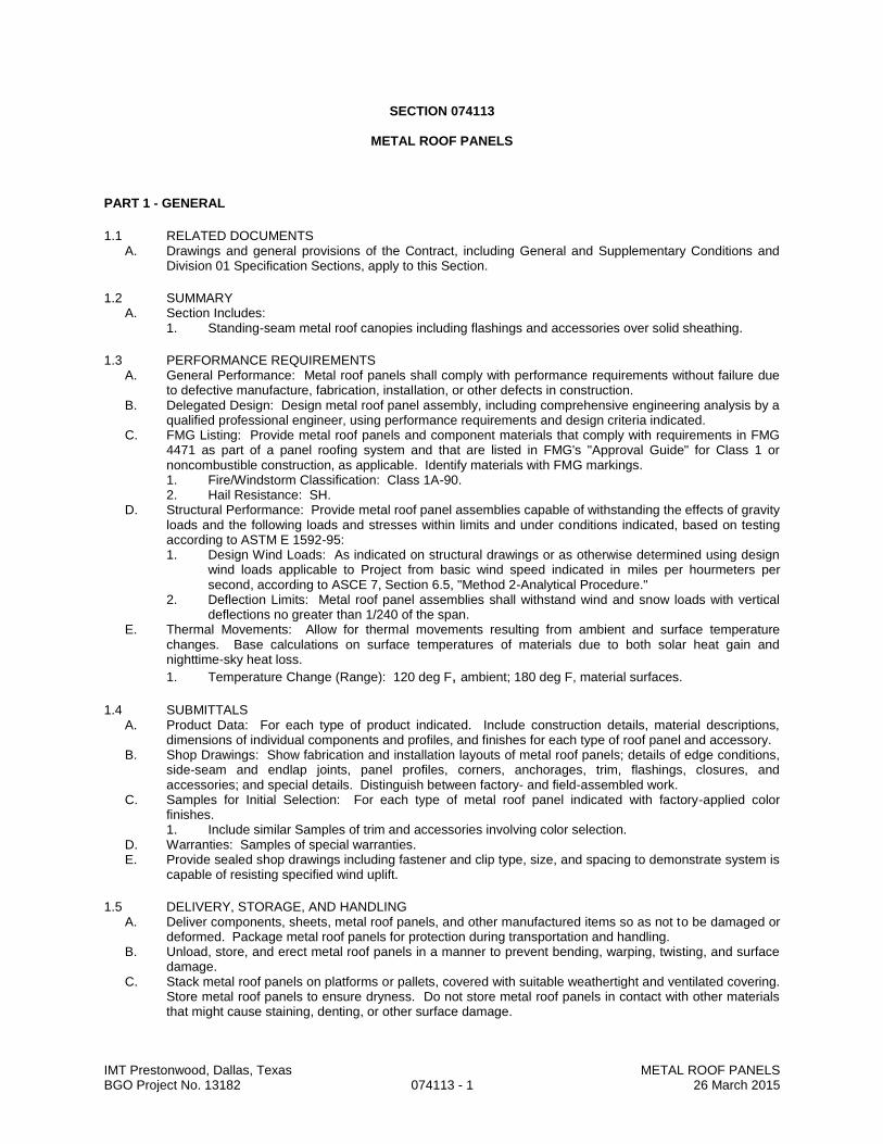
IMT Prestonwood, Dallas, Texas METAL ROOF PANELS BGO Project No. 13182 074113 - 1 26 March 2015
SECTION 074113
METAL ROOF PANELS
PART 1 - GENERAL
1.1 RELATED DOCUMENTS A. Drawings and general provisions of the Contract, including General and Supplementary Conditions and
Division 01 Specification Sections, apply to this Section.
1.2 SUMMARY A. Section Includes:
1. Standing-seam metal roof canopies including flashings and accessories over solid sheathing.
1.3 PERFORMANCE REQUIREMENTS A. General Performance: Metal roof panels shall comply with performance requirements without failure due
to defective manufacture, fabrication, installation, or other defects in construction. B. Delegated Design: Design metal roof panel assembly, including comprehensive engineering analysis by a
qualified professional engineer, using performance requirements and design criteria indicated. C. FMG Listing: Provide metal roof panels and component materials that comply with requirements in FMG
4471 as part of a panel roofing system and that are listed in FMG's "Approval Guide" for Class 1 or noncombustible construction, as applicable. Identify materials with FMG markings. 1. Fire/Windstorm Classification: Class 1A-90. 2. Hail Resistance: SH.
D. Structural Performance: Provide metal roof panel assemblies capable of withstanding the effects of gravity loads and the following loads and stresses within limits and under conditions indicated, based on testing according to ASTM E 1592-95: 1. Design Wind Loads: As indicated on structural drawings or as otherwise determined using design
wind loads applicable to Project from basic wind speed indicated in miles per hourmeters per second, according to ASCE 7, Section 6.5, "Method 2-Analytical Procedure."
2. Deflection Limits: Metal roof panel assemblies shall withstand wind and snow loads with vertical deflections no greater than 1/240 of the span.
E. Thermal Movements: Allow for thermal movements resulting from ambient and surface temperature changes. Base calculations on surface temperatures of materials due to both solar heat gain and nighttime-sky heat loss.
1. Temperature Change (Range): 120 deg F, ambient; 180 deg F, material surfaces.
1.4 SUBMITTALS A. Product Data: For each type of product indicated. Include construction details, material descriptions,
dimensions of individual components and profiles, and finishes for each type of roof panel and accessory. B. Shop Drawings: Show fabrication and installation layouts of metal roof panels; details of edge conditions,
side-seam and endlap joints, panel profiles, corners, anchorages, trim, flashings, closures, and accessories; and special details. Distinguish between factory- and field-assembled work.
C. Samples for Initial Selection: For each type of metal roof panel indicated with factory-applied color finishes. 1. Include similar Samples of trim and accessories involving color selection.
D. Warranties: Samples of special warranties. E. Provide sealed shop drawings including fastener and clip type, size, and spacing to demonstrate system is
capable of resisting specified wind uplift.
1.5 DELIVERY, STORAGE, AND HANDLING A. Deliver components, sheets, metal roof panels, and other manufactured items so as not to be damaged or
deformed. Package metal roof panels for protection during transportation and handling. B. Unload, store, and erect metal roof panels in a manner to prevent bending, warping, twisting, and surface
damage. C. Stack metal roof panels on platforms or pallets, covered with suitable weathertight and ventilated covering.
Store metal roof panels to ensure dryness. Do not store metal roof panels in contact with other materials that might cause staining, denting, or other surface damage.
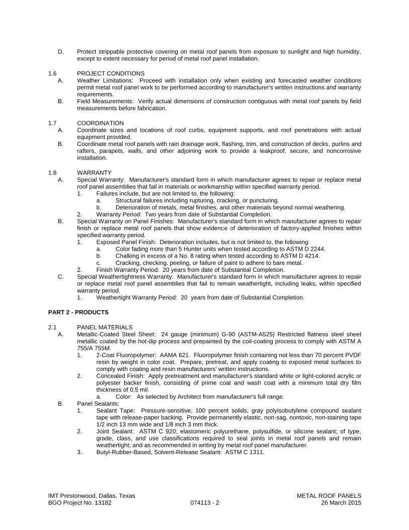
IMT Prestonwood, Dallas, Texas METAL ROOF PANELS BGO Project No. 13182 074113 - 2 26 March 2015
D. Protect strippable protective covering on metal roof panels from exposure to sunlight and high humidity, except to extent necessary for period of metal roof panel installation.
1.6 PROJECT CONDITIONS A. Weather Limitations: Proceed with installation only when existing and forecasted weather conditions
permit metal roof panel work to be performed according to manufacturer's written instructions and warranty requirements.
B. Field Measurements: Verify actual dimensions of construction contiguous with metal roof panels by field measurements before fabrication.
1.7 COORDINATION A. Coordinate sizes and locations of roof curbs, equipment supports, and roof penetrations with actual
equipment provided. B. Coordinate metal roof panels with rain drainage work, flashing, trim, and construction of decks, purlins and
rafters, parapets, walls, and other adjoining work to provide a leakproof, secure, and noncorrosive installation.
1.8 WARRANTY A. Special Warranty: Manufacturer's standard form in which manufacturer agrees to repair or replace metal
roof panel assemblies that fail in materials or workmanship within specified warranty period. 1. Failures include, but are not limited to, the following:
a. Structural failures including rupturing, cracking, or puncturing. b. Deterioration of metals, metal finishes, and other materials beyond normal weathering.
2. Warranty Period: Two years from date of Substantial Completion. B. Special Warranty on Panel Finishes: Manufacturer's standard form in which manufacturer agrees to repair
finish or replace metal roof panels that show evidence of deterioration of factory-applied finishes within specified warranty period. 1. Exposed Panel Finish: Deterioration includes, but is not limited to, the following:
a. Color fading more than 5 Hunter units when tested according to ASTM D 2244. b. Chalking in excess of a No. 8 rating when tested according to ASTM D 4214. c. Cracking, checking, peeling, or failure of paint to adhere to bare metal.
2. Finish Warranty Period: 20 years from date of Substantial Completion. C. Special Weathertightness Warranty: Manufacturer's standard form in which manufacturer agrees to repair
or replace metal roof panel assemblies that fail to remain weathertight, including leaks, within specified warranty period. 1. Weathertight Warranty Period: 20 years from date of Substantial Completion.
PART 2 - PRODUCTS
2.1 PANEL MATERIALS A. Metallic-Coated Steel Sheet: 24 gauge (minimum) G-90 (ASTM-A525) Restricted flatness steel sheet
metallic coated by the hot-dip process and prepainted by the coil-coating process to comply with ASTM A 755/A 755M. 1. 2-Coat Fluoropolymer: AAMA 621. Fluoropolymer finish containing not less than 70 percent PVDF
resin by weight in color coat. Prepare, pretreat, and apply coating to exposed metal surfaces to comply with coating and resin manufacturers' written instructions.
2. Concealed Finish: Apply pretreatment and manufacturer's standard white or light-colored acrylic or polyester backer finish, consisting of prime coat and wash coat with a minimum total dry film thickness of 0.5 mil. a. Color: As selected by Architect from manufacturer's full range.
B. Panel Sealants: 1. Sealant Tape: Pressure-sensitive, 100 percent solids, gray polyisobutylene compound sealant
tape with release-paper backing. Provide permanently elastic, non-sag, nontoxic, non-staining tape 1/2 inch 13 mm wide and 1/8 inch 3 mm thick.
2. Joint Sealant: ASTM C 920; elastomeric polyurethane, polysulfide, or silicone sealant; of type, grade, class, and use classifications required to seal joints in metal roof panels and remain weathertight; and as recommended in writing by metal roof panel manufacturer.
3. Butyl-Rubber-Based, Solvent-Release Sealant: ASTM C 1311.
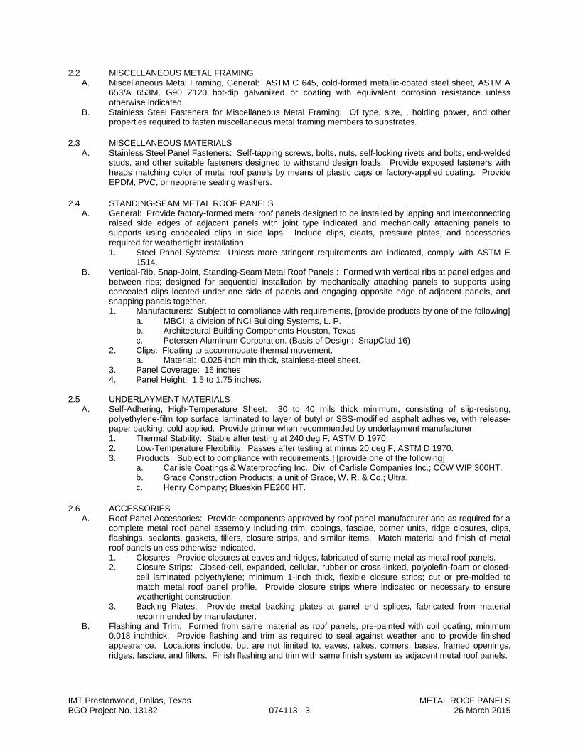
IMT Prestonwood, Dallas, Texas METAL ROOF PANELS BGO Project No. 13182 074113 - 3 26 March 2015
2.2 MISCELLANEOUS METAL FRAMING A. Miscellaneous Metal Framing, General: ASTM C 645, cold-formed metallic-coated steel sheet, ASTM A
653/A 653M, G90 Z120 hot-dip galvanized or coating with equivalent corrosion resistance unless otherwise indicated.
B. Stainless Steel Fasteners for Miscellaneous Metal Framing: Of type, size, , holding power, and other properties required to fasten miscellaneous metal framing members to substrates.
2.3 MISCELLANEOUS MATERIALS A. Stainless Steel Panel Fasteners: Self-tapping screws, bolts, nuts, self-locking rivets and bolts, end-welded
studs, and other suitable fasteners designed to withstand design loads. Provide exposed fasteners with heads matching color of metal roof panels by means of plastic caps or factory-applied coating. Provide EPDM, PVC, or neoprene sealing washers.
2.4 STANDING-SEAM METAL ROOF PANELS A. General: Provide factory-formed metal roof panels designed to be installed by lapping and interconnecting
raised side edges of adjacent panels with joint type indicated and mechanically attaching panels to supports using concealed clips in side laps. Include clips, cleats, pressure plates, and accessories required for weathertight installation. 1. Steel Panel Systems: Unless more stringent requirements are indicated, comply with ASTM E
1514. B. Vertical-Rib, Snap-Joint, Standing-Seam Metal Roof Panels : Formed with vertical ribs at panel edges and
between ribs; designed for sequential installation by mechanically attaching panels to supports using concealed clips located under one side of panels and engaging opposite edge of adjacent panels, and snapping panels together. 1. Manufacturers: Subject to compliance with requirements, [provide products by one of the following]
a. MBCI; a division of NCI Building Systems, L. P. b. Architectural Building Components Houston, Texas c. Petersen Aluminum Corporation. (Basis of Design: SnapClad 16)
2. Clips: Floating to accommodate thermal movement. a. Material: 0.025-inch min thick, stainless-steel sheet.
3. Panel Coverage: 16 inches 4. Panel Height: 1.5 to 1.75 inches.
2.5 UNDERLAYMENT MATERIALS
A. Self-Adhering, High-Temperature Sheet: 30 to 40 mils thick minimum, consisting of slip-resisting, polyethylene-film top surface laminated to layer of butyl or SBS-modified asphalt adhesive, with release-paper backing; cold applied. Provide primer when recommended by underlayment manufacturer. 1. Thermal Stability: Stable after testing at 240 deg F; ASTM D 1970. 2. Low-Temperature Flexibility: Passes after testing at minus 20 deg F; ASTM D 1970. 3. Products: Subject to compliance with requirements,] [provide one of the following]
a. Carlisle Coatings & Waterproofing Inc., Div. of Carlisle Companies Inc.; CCW WIP 300HT. b. Grace Construction Products; a unit of Grace, W. R. & Co.; Ultra. c. Henry Company; Blueskin PE200 HT.
2.6 ACCESSORIES A. Roof Panel Accessories: Provide components approved by roof panel manufacturer and as required for a
complete metal roof panel assembly including trim, copings, fasciae, corner units, ridge closures, clips, flashings, sealants, gaskets, fillers, closure strips, and similar items. Match material and finish of metal roof panels unless otherwise indicated. 1. Closures: Provide closures at eaves and ridges, fabricated of same metal as metal roof panels. 2. Closure Strips: Closed-cell, expanded, cellular, rubber or cross-linked, polyolefin-foam or closed-
cell laminated polyethylene; minimum 1-inch thick, flexible closure strips; cut or pre-molded to match metal roof panel profile. Provide closure strips where indicated or necessary to ensure weathertight construction.
3. Backing Plates: Provide metal backing plates at panel end splices, fabricated from material recommended by manufacturer.
B. Flashing and Trim: Formed from same material as roof panels, pre-painted with coil coating, minimum 0.018 inchthick. Provide flashing and trim as required to seal against weather and to provide finished appearance. Locations include, but are not limited to, eaves, rakes, corners, bases, framed openings, ridges, fasciae, and fillers. Finish flashing and trim with same finish system as adjacent metal roof panels.

IMT Prestonwood, Dallas, Texas METAL ROOF PANELS BGO Project No. 13182 074113 - 4 26 March 2015
2.7 FABRICATION A. Fabricate and finish metal roof panels and accessories at the factory to greatest extent possible, by
manufacturer's standard procedures and processes and as necessary to fulfill indicated performance requirements. Comply with indicated profiles and with dimensional and structural requirements.
B. Provide panel profile, including major ribs and intermediate stiffening ribs, if any, for full length of panel. C. Fabricate metal roof panel side laps with factory-installed captive gaskets or separator strips that provide a
tight seal and prevent metal-to-metal contact, in a manner that will seal weathertight and minimize noise from movements within panel assembly.
D. Sheet Metal Accessories: Fabricate flashing and trim to comply with recommendations in SMACNA's "Architectural Sheet Metal Manual" that apply to the design, dimensions, metal, and other characteristics of item indicated. 1. Form exposed sheet metal accessories that are without excessive oil canning, buckling, and tool
marks and that are true to line and levels indicated, with exposed edges folded back to form hems. 2. End Seams for Aluminum: Fabricate nonmoving seams with flat-lock seams. Form seams and
seal with epoxy seam sealer. Rivet joints for additional strength. 3. End Seams for Other Than Aluminum: Fabricate nonmoving seams with flat-lock seams. Tin
edges to be seamed, form seams, and solder. 4. Sealed Joints: Form non-expansion but movable joints in metal to accommodate elastomeric
sealant to comply with SMACNA standards. 5. Conceal fasteners and expansion provisions where possible. Exposed fasteners are not allowed
on faces of accessories exposed to view. 6. Fabricate cleats and attachment devices of size and metal thickness recommended by SMACNA's
"Architectural Sheet Metal Manual" or by metal roof panel manufacturer for application, but not less than thickness of metal being secured.
2.8 FINISHES A. Comply with NAAMM's "Metal Finishes Manual for Architectural and Metal Products" for recommendations
for applying and designating finishes. B. Appearance of Finished Work: Noticeable variations in same piece are not acceptable. Variations in
appearance of adjoining components are acceptable if they are within the range of approved Samples and are assembled or installed to minimize contrast.
PART 3 - EXECUTION
3.1 EXAMINATION A. Examine substrates, areas, and conditions, with Installer present, for compliance with requirements for
installation tolerances, metal roof panel supports, and other conditions affecting performance of the Work. B. Examine primary and secondary roof framing to verify that rafters, purlins, angles, channels, and other
structural panel support members and anchorages have been installed within alignment tolerances required by metal roof panel manufacturer.
C. Examine roughing-in for components and systems penetrating metal roof panels to verify actual locations of penetrations relative to seam locations of metal roof panels before metal roof panel installation.
D. For the record, prepare written report, endorsed by Installer, listing conditions detrimental to performance of the Work.
E. Proceed with installation only after unsatisfactory conditions have been corrected.
3.2 PREPARATION A. Clean substrates of substances harmful to insulation, including removing projections capable of interfering
with insulation attachment. B. Miscellaneous Framing: Install subpurlins, eave angles, furring, and other miscellaneous roof panel
support members and anchorage according to metal roof panel manufacturer's written instructions.
3.3 UNDERLAYMENT INSTALLATION A. Self-Adhering Sheet Underlayment: Apply primer if required by manufacturer. Comply with temperature
restrictions of underlayment manufacturer for installation. Apply at locations indicated below, wrinkle free, in shingle fashion to shed water, and with end laps of not less than 6 inches staggered 24 inches between courses. Overlap side edges not less than 3-1/2 inches. Roll laps with roller. Cover underlayment within 14 days. 1. Install beneath entire roof surface.
B. Install flashings to cover underlayment to comply with requirements specified in Division 07 Section "Sheet Metal Flashing and Trim."

IMT Prestonwood, Dallas, Texas METAL ROOF PANELS BGO Project No. 13182 074113 - 5 26 March 2015
3.4 METAL ROOF PANEL INSTALLATION, GENERAL A. Provide metal roof panels of full length from eave to ridge unless otherwise indicated or restricted by
shipping limitations. B. Thermal Movement. Rigidly fasten metal roof panels to structure at one and only one location for each
panel. Allow remainder of panel to move freely for thermal expansion and contraction. Predrill panels for fasteners. 1. Avoid attaching accessories through roof panels in a manner that will inhibit thermal movement.
C. Install metal roof panels as follows: 1. Commence metal roof panel installation and install minimum of 300 sq. ft. in presence of factory-
authorized representative. 2. Field cutting of metal panels by torch is not permitted. 3. Install panels perpendicular to purlins. 4. Locate and space fastenings in uniform vertical and horizontal alignment. 5. Provide metal closures at [rake edges] [rake walls] [and] each side of ridge[ and hip] caps. 6. Flash and seal metal roof panels with weather closures at eaves, rakes, and perimeter of all
openings. 7. End Splices: Locate panel end splices over, but not attached to, structural supports. Stagger panel
end splices to avoid a four-panel splice condition. 8. Install metal flashing to allow moisture to run over and off metal roof panels.
D. Fasteners: 1. Steel Roof Panels: Use stainless-steel fasteners for surfaces exposed to the exterior and
stainless-steel fasteners for surfaces exposed to the interior. E. Anchor Clips: Anchor metal roof panels and other components of the Work securely in place, using
manufacturer's approved fasteners according to manufacturers' written instructions. F. Joint Sealers: Install gaskets, joint fillers, and sealants where indicated and where required for
weatherproof performance of metal roof panel assemblies. Provide types of gaskets, fillers, and sealants indicated or, if not indicated, types recommended by metal roof panel manufacturer. 1. Seal metal roof panel end laps with double beads of tape or sealant, full width of panel. Seal side
joints where recommended by metal roof panel manufacturer. 2. Prepare joints and apply sealants to comply with requirements in Division 07 Section "Joint
Sealants."
3.5 METAL ROOF PANEL INSTALLATION A. Standing-Seam Metal Roof Panels: Fasten metal roof panels to supports with concealed clips at each
standing-seam joint at location, spacing, and with fasteners recommended by manufacturer. 1. Install clips to supports with self-tapping fasteners. 2. Install pressure plates at locations indicated in manufacturer's written installation instructions. 3. Snap Joint: Nest standing seams and fasten together by interlocking and completely engaging
factory-applied sealant.
3.6 ACCESSORY INSTALLATION A. General: Install accessories with positive anchorage to building and weathertight mounting and provide for
thermal expansion. Coordinate installation with flashings and other components. 1. Install components required for a complete metal roof panel assembly including trim, copings, ridge
closures, seam covers, flashings, sealants, gaskets, fillers, closure strips, and similar items. B. Flashing and Trim: Comply with performance requirements, manufacturer's written installation
instructions, and SMACNA's "Architectural Sheet Metal Manual." Provide concealed fasteners where possible, and set units true to line and level as indicated. Install work with laps, joints, and seams that will be permanently watertight and weather resistant. 1. Install exposed flashing and trim that is without excessive oil canning, buckling, and tool marks and
that is true to line and levels indicated, with exposed edges folded back to form hems. Install sheet metal flashing and trim to fit substrates and to result in waterproof and weather-resistant performance.
2. Expansion Provisions: Provide for thermal expansion of exposed flashing and trim. Space movement joints at a maximum of 10 feet 3 m with no joints allowed within 24 inches 600 mm of corner or intersection. Where lapped expansion provisions cannot be used or would not be sufficiently weather resistant and waterproof, form expansion joints of intermeshing hooked flanges, not less than 1 inch 25 mm deep, filled with mastic sealant (concealed within joints).

IMT Prestonwood, Dallas, Texas METAL ROOF PANELS BGO Project No. 13182 074113 - 6 26 March 2015
3.7 ERECTION TOLERANCES A. Installation Tolerances: Shim and align metal roof panel units within installed tolerance of 1/4 inch in 20
feet on slope and location lines as indicated and within 1/8-inch offset of adjoining faces and of alignment of matching profiles.
3.8 CLEANING A. Remove temporary protective coverings and strippable films, if any, as metal roof panels are installed
unless otherwise indicated in manufacturer's written installation instructions. On completion of metal roof panel installation, clean finished surfaces as recommended by metal roof panel manufacturer. Maintain in a clean condition during construction.
B. Replace metal roof panels that have been damaged or have deteriorated beyond successful repair by finish touchup or similar minor repair procedures per manufacturer’s requirements.
END OF SECTION

IMT Prestonwood, Dallas, Texas PREFORMED METAL AWNINGS BGO Project No. 13182 074160 - 1 26 March 2015
SECTION 074160
PREFORMED METAL AWNINGS
PART 1 - GENERAL
1.1 RELATED DOCUMENTS A. Provisions established within General and Supplementary Conditions of the Contract, Division 1 - General
Requirements, and the Drawings are collectively applicable to this Section.
1.2 SECTION INCLUDES A. Metal panel awning system complete with related flashings, closures, trim and accessories. B. Underlayment where plywood substrate is indicated. C. Clips, anchoring, devices, fasteners, and accessories required for installation of panel system.
1.3 SYSTEM REQUIREMENTS A. Performance Requirements
1. Design and install system to accommodate thermal expansion, thermal contraction, and building movement.
2. Design system and fasteners to resist wind uplift associated with code required wind loading.
1.4 SUBMITTALS A. General: Submit following items in accordance with Section 013000. B. Product Data: Submit manufacturer's technical literature indicating properties of materials, finishes, and
performance capabilities. C. Manufacturer's Instructions: Submit written installation instructions indicating method and sequence of
installation.
1.5 DELIVERY, STORAGE AND HANDLING A. Deliver, store, handle, and protect products in accordance with Section 016000.
1.6 WARRANTY A. Provide warranties in accordance with Section 017800. B. Warrant installed system to be free of leaks and free from defects in materials and workmanship.
1. Warranty period: Two (2) years from date of Substantial Completion of project. C. Warrant factory finish to be free of cracks, splits, crazing, chipping, peeling, color fading, and rusting.
1. Warranty period: Twenty (20) years from date of Substantial Completion of project.
PART 2 - PRODUCTS
2.1 MANUFACTURERS A. Acceptable Manufacturers
1. Alumax/Howmet, Building Specialties Division, Mesquite, TX. 2. AEP Span, Dallas Corp., Dallas, TX. 3. Merchant and Evans Industries, Burlington, NJ. 4. MM Systems Corp., Tucker, GA. 5. Berridge Manufacturing Co., Houston, TX. 6. MBCI, Houston, TX.
B. Substitutions: Submit in accordance with Section 016000.
2.2 STANDING SEAM AWNING PANELS - ACCEPTABLE PRODUCTS A. Manufacturers: Subject to compliance with requirements, provide comparable to:
1. Berridge Manufacturing Cee-Lock. B. Clips: Floating to accommodate thermal movement.
1. Material: 0.025-inch min thick, stainless-steel sheet. C. Panel Coverage: 16-18 inches D. Substitutions: Submit in accordance with Section 016000.
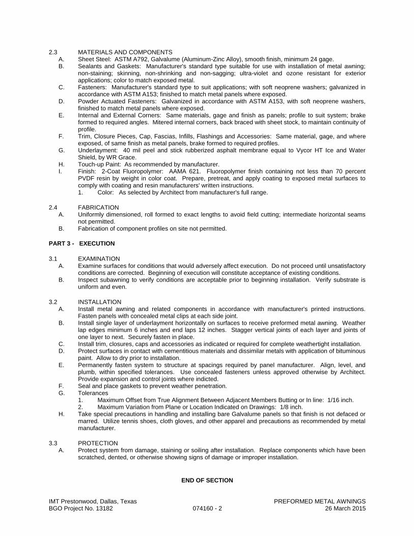
IMT Prestonwood, Dallas, Texas PREFORMED METAL AWNINGS BGO Project No. 13182 074160 - 2 26 March 2015
2.3 MATERIALS AND COMPONENTS A. Sheet Steel: ASTM A792, Galvalume (Aluminum-Zinc Alloy), smooth finish, minimum 24 gage. B. Sealants and Gaskets: Manufacturer's standard type suitable for use with installation of metal awning;
non-staining; skinning, non-shrinking and non-sagging; ultra-violet and ozone resistant for exterior applications; color to match exposed metal.
C. Fasteners: Manufacturer's standard type to suit applications; with soft neoprene washers; galvanized in accordance with ASTM A153; finished to match metal panels where exposed.
D. Powder Actuated Fasteners: Galvanized in accordance with ASTM A153, with soft neoprene washers, finished to match metal panels where exposed.
E. Internal and External Corners: Same materials, gage and finish as panels; profile to suit system; brake formed to required angles. Mitered internal corners, back braced with sheet stock, to maintain continuity of profile.
F. Trim, Closure Pieces, Cap, Fascias, Infills, Flashings and Accessories: Same material, gage, and where exposed, of same finish as metal panels, brake formed to required profiles.
G. Underlayment: 40 mil peel and stick rubberized asphalt membrane equal to Vycor HT Ice and Water Shield, by WR Grace.
H. Touch-up Paint: As recommended by manufacturer. I. Finish: 2-Coat Fluoropolymer: AAMA 621. Fluoropolymer finish containing not less than 70 percent
PVDF resin by weight in color coat. Prepare, pretreat, and apply coating to exposed metal surfaces to comply with coating and resin manufacturers' written instructions. 1. Color: As selected by Architect from manufacturer's full range.
2.4 FABRICATION A. Uniformly dimensioned, roll formed to exact lengths to avoid field cutting; intermediate horizontal seams
not permitted. B. Fabrication of component profiles on site not permitted.
PART 3 - EXECUTION
3.1 EXAMINATION A. Examine surfaces for conditions that would adversely affect execution. Do not proceed until unsatisfactory
conditions are corrected. Beginning of execution will constitute acceptance of existing conditions. B. Inspect subawning to verify conditions are acceptable prior to beginning installation. Verify substrate is
uniform and even.
3.2 INSTALLATION A. Install metal awning and related components in accordance with manufacturer's printed instructions.
Fasten panels with concealed metal clips at each side joint. B. Install single layer of underlayment horizontally on surfaces to receive preformed metal awning. Weather
lap edges minimum 6 inches and end laps 12 inches. Stagger vertical joints of each layer and joints of one layer to next. Securely fasten in place.
C. Install trim, closures, caps and accessories as indicated or required for complete weathertight installation. D. Protect surfaces in contact with cementitious materials and dissimilar metals with application of bituminous
paint. Allow to dry prior to installation. E. Permanently fasten system to structure at spacings required by panel manufacturer. Align, level, and
plumb, within specified tolerances. Use concealed fasteners unless approved otherwise by Architect. Provide expansion and control joints where indicted.
F. Seal and place gaskets to prevent weather penetration. G. Tolerances
1. Maximum Offset from True Alignment Between Adjacent Members Butting or In line: 1/16 inch. 2. Maximum Variation from Plane or Location Indicated on Drawings: 1/8 inch.
H. Take special precautions in handling and installing bare Galvalume panels so that finish is not defaced or marred. Utilize tennis shoes, cloth gloves, and other apparel and precautions as recommended by metal manufacturer.
3.3 PROTECTION A. Protect system from damage, staining or soiling after installation. Replace components which have been
scratched, dented, or otherwise showing signs of damage or improper installation.
END OF SECTION
IMT Prestonwood, Dallas, Texas METAL WALL PANELS BGO Project No. 13182 074210 - 1 26 March 2015
SECTION 074210
METAL WALL PANELS
PART 1 - GENERAL
1.1 RELATED DOCUMENTS A. Drawings and general provisions of the Contract, including General and Supplementary Conditions and
Division 01 Specification Sections, apply to this Section.
1.2 SUMMARY A. Section Includes:
1. Lap-seam metal wall panels.
1.3 DEFINITION A. Metal Wall Panel Assembly: Metal wall panels, attachment system components, miscellaneous metal
framing, thermal insulation, and accessories necessary for a complete weathertight wall system.
1.4 PERFORMANCE REQUIREMENTS A. General Performance: Metal wall panel assemblies shall comply with performance requirements
without failure due to defective manufacture, fabrication, installation, or other defects in construction. B. Delegated Design: Design metal wall panel assembly, including comprehensive engineering analysis
by a qualified professional engineer, using performance requirements and design criteria indicated. C. Air Infiltration: Air leakage through assembly of not more than 0.06 cfm/sq. ft. of wall area when tested
according to ASTM E 283 at the following test-pressure difference: 1. Test-Pressure Difference: 1.57 lbf/sq. ft..
D. Water Penetration under Static Pressure: No water penetration when tested according to ASTM E 331 at the following test-pressure difference: 1. Test-Pressure Difference: 2.86 lbf/sq. ft..
E. Water Penetration under Dynamic Pressure: No evidence of water leakage when tested according to AAMA 501.1 under dynamic pressure equal to 20 percent of inward-acting, wind-load design pressure of not less than 6.24 lbf/sq. ft. and not more than 12 lbf/sq. ft.. 1. Water Leakage: As defined according to AAMA 501.1. 2. Water Leakage: Uncontrolled water infiltrating the system or appearing on system's normally
exposed interior surfaces from sources other than condensation. Water controlled by flasing and gutters that is drained back to the exterior and cannot damage adjacent materials or finishes is not water leakage.
F. Structural Performance: Provide metal wall panel assemblies capable of withstanding the effects the following loads and stresses within limits and under conditions indicated, based on testing according to ASTM E 1592: 1. Wind Loads: Determine loads based on the following minimum design wind pressures:
a. Uniform pressure as indicated on structural Drawings. 2. Deflection Limits: Metal wall panel assemblies shall withstand wind loads with horizontal
deflections no greater than 1/240 of the span. G. Thermal Movements: Allow for thermal movements from ambient and surface temperature changes by
preventing buckling, opening of joints, overstressing of components, failure of joint sealants, failure of connections, and other detrimental effects. Base calculations on surface temperatures of materials due to both solar heat gain and nighttime-sky heat loss. 1. Temperature Change (Range): 120 deg F, ambient; 180 deg F, material surfaces.
IMT Prestonwood, Dallas, Texas METAL WALL PANELS BGO Project No. 13182 074210 - 2 26 March 2015
1.5 SUBMITTALS A. Product Data: For each type of product indicated. Include construction details, material descriptions,
dimensions of individual components and profiles, and finishes for each type of wall panel and accessory.
B. Shop Drawings: Show fabrication and installation layouts of metal wall panels; details of edge conditions, joints, panel profiles, corners, anchorages, attachment system, trim, flashings, closures, and accessories; and special details. Distinguish between factory-, shop- and field-assembled work. Shop drawings shall be signed and sealed by a professional engineer registered in the State of Texas. 1. Accessories: Include details of the following items, at a scale of not less than 1-1/2 inches per
12 inches: a. Flashing and trim. b. Anchorage systems.
C. Samples for Initial Selection: For each type of metal wall panel indicated with factory-applied color finishes. 1. Include similar Samples of trim and accessories involving color selection. 2. Include manufacturer's color charts consisting of strips of cured sealants showing the full range
of colors available for each sealant exposed to view. D. Provide mock-up, not less than 10 feet in length, demonstrating physical appearance of completed
system.
1.6 DELIVERY, STORAGE, AND HANDLING A. Deliver components, sheets, metal wall panels, and other manufactured items so as not to be
damaged or deformed. Package metal wall panels for protection during transportation and handling. B. Unload, store, and erect metal wall panels in a manner to prevent bending, warping, twisting, and
surface damage. C. Stack metal wall panels horizontally on platforms or pallets, covered with suitable weathertight and
ventilated covering. Store metal wall panels to ensure dryness, with positive slope for drainage of water. Do not store metal wall panels in contact with other materials that might cause staining, denting, or other surface damage.
1.7 PROJECT CONDITIONS A. Weather Limitations: Proceed with installation only when existing and forecasted weather conditions
permit assembly of metal wall panels to be performed according to manufacturers' written instructions and warranty requirements.
B. Field Measurements: Verify locations of structural members and wall opening dimensions by field measurements before metal wall panel fabrication, and indicate measurements on Shop Drawings.
1.8 COORDINATION A. Coordinate metal wall panel assemblies with rain drainage work, flashing, trim, and construction of
girts, soffits, and other adjoining work to provide a leakproof, secure, and non-corrosive installation.
1.9 WARRANTY A. Special Warranty: Manufacturer's standard form in which manufacturer agrees to repair or replace
components of metal wall panel assemblies that fail in materials or workmanship within specified warranty period. 1. Failures include, but are not limited to, the following:
a. Structural failures including rupturing, cracking, or puncturing. b. Deterioration of metals and other materials beyond normal weathering.
2. Warranty Period: Five years from date of Substantial Completion. B. Special Warranty on Panel Finishes: Manufacturer's standard form in which manufacturer agrees to
repair finish or replace metal wall panels that show evidence of deterioration of factory-applied finishes within specified warranty period. 1. Exposed Panel Finish: Deterioration includes, but is not limited to, the following:
a. Color fading more than 5 Hunter units when tested according to ASTM D 2244. b. Chalking in excess of a No. 8 rating when tested according to ASTM D 4214. c. Cracking, checking, peeling, or failure of paint to adhere to bare metal.
2. Finish Warranty Period: 20 years from date of Substantial Completion.
IMT Prestonwood, Dallas, Texas METAL WALL PANELS BGO Project No. 13182 074210 - 3 26 March 2015
PART 2 - PRODUCTS
2.1 PANEL MATERIALS A. Metallic-Coated Steel Sheet: Restricted flatness steel sheet metallic coated by the hot-dip process and
pre-painted by the coil-coating process to comply with ASTM A 755. 1. Aluminum-Zinc Alloy-Coated Steel Sheet: ASTM A 792, Class AZ50 coating designation,
Grade 40; structural quality. 2. Surface: Smooth, flat finish. 3. Exposed Coil-Coated Finish:
a. 2-Coat Fluoropolymer: AAMA 621. Fluoropolymer finish containing not less than 70 percent PVDF resin by weight in color coat. Prepare, pre-treat, and apply coating to exposed metal surfaces to comply with coating and resin manufacturers' written instructions.
4. Concealed Finish: Apply pretreatment and manufacturer's standard white or light-colored acrylic or polyester backer finish consisting of prime coat and wash coat with a minimum total dry film thickness of 0.5 mil.
B. Panel Sealants: 1. Sealant Tape: Pressure-sensitive, 100 percent solids, gray polyisobutylene compound sealant
tape with release-paper backing. Provide permanently elastic, non-sag, nontoxic, non-staining tape 1/2 inch wide and 1/8 inch thick.
2. Joint Sealant: ASTM C 920; elastomeric silicone sealant; of type, grade, class, and use classifications required to seal joints in metal wall panels and remain weathertight; and as recommended in writing by metal wall panel manufacturer.
3. Butyl-Rubber-Based, Solvent-Release Sealant: ASTM C 1311.
2.2 MISCELLANEOUS METAL FRAMING A. Miscellaneous Metal Framing, General: ASTM C 645, cold-formed metallic-coated steel sheet, ASTM
A 653, G90s hot-dip galvanized or coating with equivalent corrosion resistance unless otherwise indicated.
B. Subgirts: Manufacturer's standard C- or Z-shaped sections, 0.064-inch nominal thickness. C. Zee Clips: 0.079-inch nominal thickness. D. Base or Sill Angles: 0.079-inch nominal thickness. E. Hat-Shaped, Rigid Furring Channels:
1. Nominal Thickness: As required to meet performance requirements. 2. Depth: 7/8 inch.
F. Cold-Rolled Furring Channels: Minimum 1/2-inch- wide flange. 1. Nominal Thickness: As required to meet performance requirements. 2. Depth: 3/4 inch. 3. Tie Wire: ASTM A 641/A 641M, Class 1 zinc coating, soft temper, 0.062-inch- diameter wire, or
double strand of 0.048-inch- diameter wire. G. Z-Shaped Furring: With slotted or nonslotted web, face flange of 1-1/4 inches, wall attachment flange
of 7/8 inch, and depth required to fit insulation thickness indicated. 1. Nominal Thickness: As required to meet performance requirements.
H. Fasteners for Miscellaneous Metal Framing: Of type, material, size, corrosion resistance, holding power, and other properties required to fasten miscellaneous metal framing members to substrates.
2.3 MISCELLANEOUS MATERIALS A. Panel Fasteners: Self-tapping screws, bolts, nuts, self-locking rivets and bolts, end-welded studs, and
other suitable fasteners designed to withstand design loads. Provide exposed fasteners with heads matching color of metal wall panels by means of plastic caps or factory-applied coating. Provide EPDM, PVC, or neoprene sealing washers.
IMT Prestonwood, Dallas, Texas METAL WALL PANELS BGO Project No. 13182 074210 - 4 26 March 2015
2.4 LAP-SEAM METAL WALL PANELS A. General: Provide factory-formed metal wall panels designed to be field assembled by lapping side
edges of adjacent panels and mechanically attaching panels to supports using concealed fasteners. Include accessories required for weathertight installation.
B. Profile: Formed with alternating ribs across width of panel. 1. Subject to compliance with requirements, provide product indicated in the Finish Legend or
comparable product by one of the following: a. ATAS International, Inc. b. CENTRIA Architectural Systems. c. MBCI; Div. of NCI Building Systems. d. McElroy Metal, Inc. e. Metal Sales Manufacturing Corporation. f. Morin; a Kingspan Group Company g. Firestone (Basis of Design: Delta series concealed fastener system).
2. Material: Aluminum-zinc alloy-coated steel sheet, nominal thickness as recommended by manufacturer for spans encountered. a. Exterior Finish: 2-coat fluoropolymer. b. Color: As selected by Architect from manufacturer's full range. c. Acceptable Product: Refer to Finish Legend.
2.5 ACCESSORIES A. Wall Panel Accessories: Provide components required for a complete metal wall panel assembly
including trim, copings, fasciae, mullions, sills, corner units, clips, flashings, sealants, gaskets, fillers, closure strips, and similar items. Match material and finish of metal wall panels, unless otherwise indicated. 1. Closures: Provide closures at eaves and rakes, fabricated of same metal as metal wall panels. 2. Backing Plates: Provide metal backing plates at panel end splices, fabricated from material
recommended by manufacturer. 3. Closure Strips: Closed-cell, expanded, cellular, rubber or cross-linked, polyolefin-foam or
closed-cell laminated polyethylene; minimum 1-inch- thick, flexible closure strips; cut or premolded to match metal wall panel profile. Provide closure strips where indicated or necessary to ensure weathertight construction.
B. Flashing and Trim: Formed from 0.018-inch minimum thickness, zinc-coated (galvanized) steel sheet or aluminum-zinc alloy-coated steel sheet pre-painted with coil coating. Provide flashing and trim as required to seal against weather and to provide finished appearance. Locations include, but are not limited to, bases, drips, sills, jambs, corners, endwalls, framed openings, rakes, fasciae, parapet caps, soffits, reveals, and fillers. Finish flashing and trim with same finish system as adjacent metal wall panels.
2.6 FABRICATION A. General: Fabricate and finish metal wall panels and accessories at the factory to greatest extent
possible, by manufacturer's standard procedures and processes, as necessary to fulfill indicated performance requirements demonstrated by laboratory testing. Comply with indicated profiles and with dimensional and structural requirements.
B. Fabricate metal wall panels in a manner that eliminates condensation on interior side of panel and with joints between panels designed to form weathertight seals.
C. Provide panel profile, including major ribs and intermediate stiffening ribs, if any, for full length of panel. D. Fabricate metal wall panel joints with factory-installed captive gaskets or separator strips that provide a
tight seal and prevent metal-to-metal contact, and that will minimize noise from movements within panel assembly.
E. Sheet Metal Accessories: Fabricate flashing and trim to comply with recommendations in SMACNA's "Architectural Sheet Metal Manual" that apply to the design, dimensions, metal, and other characteristics of item indicated. 1. Form exposed sheet metal accessories that are without excessive oil canning, buckling, and
tool marks and that are true to line and levels indicated, with exposed edges folded back to form hems.
2. Seams for Other Than Aluminum: Fabricate nonmoving seams in accessories with flat-lock seams. Tin edges to be seamed, form seams, and solder.
3. Sealed Joints: Form non-expansion but movable joints in metal to accommodate elastomeric sealant to comply with SMACNA standards.
4. Conceal fasteners and expansion provisions where possible. Exposed fasteners are not allowed on faces of accessories exposed to view.
IMT Prestonwood, Dallas, Texas METAL WALL PANELS BGO Project No. 13182 074210 - 5 26 March 2015
5. Fabricate cleats and attachment devices from same material as accessory being anchored or from compatible, non-corrosive metal recommended by metal wall panel manufacturer. a. Size: As recommended by SMACNA's "Architectural Sheet Metal Manual" or metal wall
panel manufacturer for application but not less than thickness of metal being secured.
2.7 GENERAL FINISH REQUIREMENTS A. Comply with NAAMM's "Metal Finishes Manual for Architectural and Metal Products" for
recommendations for applying and designating finishes. B. Protect mechanical and painted finishes on exposed surfaces from damage by applying a strippable,
temporary protective covering before shipping. C. Appearance of Finished Work: Noticeable variations in finish and appearance, as determined by
Architect, are not acceptable.
PART 3 - EXECUTION
3.1 EXAMINATION A. Examine substrates, areas, and conditions, with Installer present, for compliance with requirements for
installation tolerances, metal wall panel supports, and other conditions affecting performance of work. 1. Examine wall framing to verify that girts, angles, channels, studs, and other structural panel
support members and anchorage have been installed within alignment tolerances required by metal wall panel manufacturer.
2. Examine wall sheathing to verify that sheathing joints are supported by framing or blocking and that installation is within flatness tolerances required by metal wall panel manufacturer.
3. Verify that weather-resistant sheathing paper has been installed over sheathing or backing substrate to prevent air infiltration or water penetration.
4. For the record, prepare written report, endorsed by Installer, listing conditions detrimental to performance of work.
B. Examine roughing-in for components and systems penetrating metal wall panels to verify actual locations of penetrations relative to seam locations of metal wall panels before metal wall panel installation.
C. Proceed with installation only after unsatisfactory conditions have been corrected.
3.2 PREPARATION A. Miscellaneous Framing: Install subgirts, base angles, sills, furring, and other miscellaneous wall panel
support members and anchorages according to ASTM C 754 and metal wall panel manufacturer's written recommendations. 1. Soffit Framing: Clip furring channels to supports, as required to comply with requirements for
assemblies indicated.
3.3 METAL WALL PANEL INSTALLATION A. General: Install metal wall panels according to manufacturer's written instructions in orientation, sizes,
and locations indicated on Drawings. Install panels perpendicular to girts and subgirts unless otherwise indicated. Anchor metal wall panels and other components of the Work securely in place, with provisions for thermal and structural movement. 1. Commence metal wall panel installation and install minimum of 300 sq. ft. in presence of
factory-authorized representative. 2. Shim or otherwise plumb substrates receiving metal wall panels. 3. Flash and seal metal wall panels at perimeter of all openings. Fasten with self-tapping screws.
Do not begin installation until weather barrier and flashings that will be concealed by metal wall panels are installed.
4. Install screw fasteners in predrilled holes. 5. Locate and space fastenings in uniform vertical and horizontal alignment. 6. Install flashing and trim as metal wall panel work proceeds. 7. Locate panel splices over, but not attached to, structural supports. Stagger panel splices and
end laps to avoid a four-panel lap splice condition. 8. Apply elastomeric sealant continuously between metal base channel (sill angle) and concrete
and elsewhere as indicated or, if not indicated, as necessary for waterproofing. 9. Align bottom of metal wall panels and fasten with blind rivets, bolts, or self-tapping screws.
Fasten flashings and trim around openings and similar elements with self-tapping screws. 10. Provide weathertight escutcheons for pipe and conduit penetrating exterior walls.
B. Fasteners: 1. Steel Wall Panels: Use stainless-steel fasteners for surfaces exposed to the exterior; use
IMT Prestonwood, Dallas, Texas METAL WALL PANELS BGO Project No. 13182 074210 - 6 26 March 2015
galvanized steel fasteners for surfaces exposed to the interior. C. Metal Protection: Where dissimilar metals will contact each other or corrosive substrates, protect
against galvanic action as recommended by metal wall panel manufacturer. D. Joint Sealers: Install gaskets, joint fillers, and sealants where indicated and where required for
weathertight performance of metal wall panel assemblies. Provide types of gaskets, fillers, and sealants indicated or, if not indicated, types recommended by metal wall panel manufacturer. 1. Seal metal wall panel end laps with double beads of tape or sealant, full width of panel. Seal
side joints where recommended by metal wall panel manufacturer. 2. Prepare joints and apply sealants to comply with requirements in Division 07 Section "Joint
Sealants." E. Lap-Seam Metal Wall Panels: Fasten metal wall panels to supports with fasteners at each lapped joint
at location and spacing recommended by manufacturer. 1. Lap ribbed or fluted sheets one full rib corrugation. Apply panels and associated items for neat
and weathertight enclosure. Avoid "panel creep" or application not true to line. 2. Provide metal-backed washers under heads of exposed fasteners bearing on weather side of
metal wall panels. 3. Locate and space fasteners in uniform vertical and horizontal alignment. Use proper tools to
obtain controlled uniform compression for positive seal without rupture of washer. 4. Install screw fasteners with power tools having controlled torque adjusted to compress washer
tightly without damage to washer, screw threads, or panels. Install screws in predrilled holes. 5. Provide sealant tape at lapped joints of metal wall panels and between panels and protruding
equipment, vents, and accessories. 6. At panel splices, nest panels with minimum 6-inch end lap, sealed with butyl-rubber sealant and
fastened together by interlocking clamping plates. F. Zee Clips: Provide Zee clips of size indicated or, if not indicated, as required to act as standoff from
subgirts for thickness of insulation indicated. Attach to subgirts with fasteners.
3.4 ACCESSORY INSTALLATION A. General: Install accessories with positive anchorage to building and weathertight mounting, and
provide for thermal expansion. Coordinate installation with flashings and other components. 1. Install components required for a complete metal wall panel assembly including trim, copings,
corners, seam covers, flashings, sealants, gaskets, fillers, closure strips, and similar items. B. Flashing and Trim: Comply with performance requirements, manufacturer's written installation
instructions, and SMACNA's "Architectural Sheet Metal Manual." Provide concealed fasteners where possible, and set units true to line and level as indicated. Install work with laps, joints, and seams that will be permanently watertight and weather resistant. 1. Install exposed flashing and trim that is without excessive oil canning, buckling, and tool marks
and that is true to line and levels indicated, with exposed edges folded back to form hems. Install sheet metal flashing and trim to fit substrates and to result in waterproof and weather-resistant performance.
2. Expansion Provisions: Provide for thermal expansion of exposed flashing and trim. Space movement joints at a maximum of 10 feet with no joints allowed within 24 inches of corner or intersection. Where lapped expansion provisions cannot be used or would not be sufficiently weather resistant and waterproof, form expansion joints of intermeshing hooked flanges, not less than 1 inch deep, filled with mastic sealant (concealed within joints).
3.5 CLEANING AND PROTECTION A. Remove temporary protective coverings and strippable films, if any, as metal wall panels are installed,
unless otherwise indicated in manufacturer's written installation instructions. On completion of metal wall panel installation, clean finished surfaces as recommended by metal wall panel manufacturer. Maintain in a clean condition during construction.
B. After metal wall panel installation, clear weep holes and drainage channels of obstructions, dirt, and sealant.
C. Replace metal wall panels that have been damaged or have deteriorated beyond successful repair by finish touchup or similar minor repair procedures.
END OF SECTION
IMT Prestonwood, Dallas, Texas ALUMINUM COMPOSITE PANEL SYSTEM BGO Project No. 13182 074243 - 1 26 March 2015
SECTION 074243
ALUMINUM COMPOSITE PANEL SYSTEM
PART 1 - GENERAL
1.1 RELATED DOCUMENTS
A. Drawings and general provisions of the Contract, including General and Supplementary Conditions and Division 01 Specification Sections, apply to this Section.
1.2 SUMMARY A. Section includes metal-faced, composite wall panels, rain screen system with open joints and moisture
barrier behind.
1.3 DEFINITION A. Metal-Faced Composite Wall Panel Assembly: Metal-faced composite wall panels, attachment system
components, miscellaneous metal framing, and accessories necessary for a complete weathertight wall system.
1.4 PERFORMANCE REQUIREMENTS A. General Performance: Metal-faced composite wall panel assemblies shall comply with performance
requirements without failure due to defective manufacture, fabrication, installation, or other defects in construction.
B. Delegated Design: Design metal-faced composite wall panel assembly, including comprehensive engineering analysis by a qualified professional engineer, using performance requirements and design criteria indicated.
C. Air Infiltration: Air leakage through assembly of not more than 0.06 cfm/sq. ft. of wall area when tested according to ASTM E 283 at the following test-pressure difference: 1. Test-Pressure Difference: 1.57 lbf/sq. ft.
D. Water Penetration Under Static Pressure: No water penetration when tested according to ASTM E 331 at the following test-pressure difference: 1. Test-Pressure Difference: 2.86 lbf/sq. ft.
E. Water Penetration Under Dynamic Pressure: No evidence of water leakage when tested according to AAMA 501.1 under dynamic pressure equal to 20 percent of inward-acting, wind-load design pressure of not less than 6.24 lbf/sq. ft. and not more than 12 lbf/sq. ft.. 1. Water Leakage: Uncontrolled water infiltrating the system or appearing on system's normally
exposed interior surfaces from sources other than condensation. Water controlled by flashing and gutters that is drained back to the exterior and cannot damage adjacent materials or finishes is not water leakage.
F. Structural Performance: Provide metal-faced composite wall panel assemblies capable of withstanding the effects of the following loads and stresses within limits and under conditions indicated, based on testing according to ASTM E 330: 1. Design Wind Loads: As indicated on structural drawings or as otherwise determined using design
wind loads applicable to Project from basic wind speed indicated in miles per hour, according to ASCE 7, Section 6.5, "Method 2-Analytical Procedure."
2. Deflection Limits: Metal-faced composite wall panel assemblies shall withstand wind loads with horizontal deflections no greater than 1/240 of the span.
G. Thermal Movements: Allow for thermal movements from ambient and surface temperature changes by preventing buckling, opening of joints, overstressing of components, failure of joint sealants, failure of connections, and other detrimental effects. Base calculations on surface temperatures of materials due to both solar heat gain and nighttime-sky heat loss. 1. Temperature Change (Range): Minus 20 to plus 180 deg F ambient; 180 deg F material surfaces.
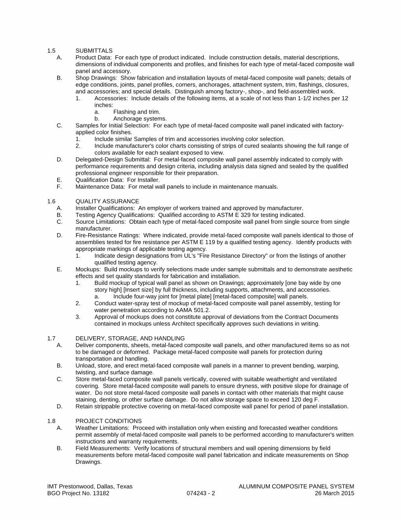
IMT Prestonwood, Dallas, Texas ALUMINUM COMPOSITE PANEL SYSTEM BGO Project No. 13182 074243 - 2 26 March 2015
1.5 SUBMITTALS A. Product Data: For each type of product indicated. Include construction details, material descriptions,
dimensions of individual components and profiles, and finishes for each type of metal-faced composite wall panel and accessory.
B. Shop Drawings: Show fabrication and installation layouts of metal-faced composite wall panels; details of edge conditions, joints, panel profiles, corners, anchorages, attachment system, trim, flashings, closures, and accessories; and special details. Distinguish among factory-, shop-, and field-assembled work. 1. Accessories: Include details of the following items, at a scale of not less than 1-1/2 inches per 12
inches: a. Flashing and trim. b. Anchorage systems.
C. Samples for Initial Selection: For each type of metal-faced composite wall panel indicated with factory-applied color finishes. 1. Include similar Samples of trim and accessories involving color selection. 2. Include manufacturer's color charts consisting of strips of cured sealants showing the full range of
colors available for each sealant exposed to view. D. Delegated-Design Submittal: For metal-faced composite wall panel assembly indicated to comply with
performance requirements and design criteria, including analysis data signed and sealed by the qualified professional engineer responsible for their preparation.
E. Qualification Data: For Installer. F. Maintenance Data: For metal wall panels to include in maintenance manuals.
1.6 QUALITY ASSURANCE A. Installer Qualifications: An employer of workers trained and approved by manufacturer. B. Testing Agency Qualifications: Qualified according to ASTM E 329 for testing indicated. C. Source Limitations: Obtain each type of metal-faced composite wall panel from single source from single
manufacturer. D. Fire-Resistance Ratings: Where indicated, provide metal-faced composite wall panels identical to those of
assemblies tested for fire resistance per ASTM E 119 by a qualified testing agency. Identify products with appropriate markings of applicable testing agency. 1. Indicate design designations from UL's "Fire Resistance Directory" or from the listings of another
qualified testing agency. E. Mockups: Build mockups to verify selections made under sample submittals and to demonstrate aesthetic
effects and set quality standards for fabrication and installation. 1. Build mockup of typical wall panel as shown on Drawings; approximately [one bay wide by one
story high] [Insert size] by full thickness, including supports, attachments, and accessories. a. Include four-way joint for [metal plate] [metal-faced composite] wall panels.
2. Conduct water-spray test of mockup of metal-faced composite wall panel assembly, testing for water penetration according to AAMA 501.2.
3. Approval of mockups does not constitute approval of deviations from the Contract Documents contained in mockups unless Architect specifically approves such deviations in writing.
1.7 DELIVERY, STORAGE, AND HANDLING A. Deliver components, sheets, metal-faced composite wall panels, and other manufactured items so as not
to be damaged or deformed. Package metal-faced composite wall panels for protection during transportation and handling.
B. Unload, store, and erect metal-faced composite wall panels in a manner to prevent bending, warping, twisting, and surface damage.
C. Store metal-faced composite wall panels vertically, covered with suitable weathertight and ventilated covering. Store metal-faced composite wall panels to ensure dryness, with positive slope for drainage of water. Do not store metal-faced composite wall panels in contact with other materials that might cause staining, denting, or other surface damage. Do not allow storage space to exceed 120 deg F.
D. Retain strippable protective covering on metal-faced composite wall panel for period of panel installation.
1.8 PROJECT CONDITIONS A. Weather Limitations: Proceed with installation only when existing and forecasted weather conditions
permit assembly of metal-faced composite wall panels to be performed according to manufacturer's written instructions and warranty requirements.
B. Field Measurements: Verify locations of structural members and wall opening dimensions by field measurements before metal-faced composite wall panel fabrication and indicate measurements on Shop Drawings.

IMT Prestonwood, Dallas, Texas ALUMINUM COMPOSITE PANEL SYSTEM BGO Project No. 13182 074243 - 3 26 March 2015
1.9 COORDINATION A. Coordinate metal-faced composite wall panel assemblies with rain drainage work, flashing, trim, and
construction of studs, soffits, and other adjoining work to provide a leakproof, secure, and noncorrosive installation.
1.10 WARRANTY A. Special Warranty: Manufacturer's standard form in which manufacturer agrees to repair or replace
components of metal-faced composite wall panel assemblies that fail in materials or workmanship within specified warranty period. 1. Failures include, but are not limited to, the following:
a. Structural failures, including rupturing, cracking, or puncturing. b. Deterioration of metals and other materials beyond normal weathering.
2. Warranty Period: Five years from date of Substantial Completion. B. Special Warranty on Panel Finishes: Manufacturer's standard form in which manufacturer agrees to repair
finish or replace metal-faced composite wall panels that show evidence of deterioration of factory-applied finishes within specified warranty period. 1. Exposed Panel Finish: Deterioration includes, but is not limited to, the following:
a. Color fading more than 5 Hunter units when tested according to ASTM D 2244. b. Chalking in excess of a No. 8 rating when tested according to ASTM D 4214. c. Cracking, checking, peeling, or failure of paint to adhere to bare metal.
2. Finish Warranty Period: 20 years from date of Substantial Completion.
PART 2 - PRODUCTS
2.1 PANEL MATERIALS A. Aluminum Sheet: Coil-coated sheet, ASTM B 209, alloy as standard with manufacturer, with temper as
required to suit forming operations and structural performance required. 1. Surface: Smooth, flat finish. 2. Exposed Coil-Coated Finishes:
a. Two-Coat Fluoropolymer: AAMA 620. Fluoropolymer finish containing not less than 70 percent PVDF resin by weight in color coat. Prepare, pretreat, and apply coating to exposed metal surfaces to comply with coating and resin manufacturers' written instructions.
3. Concealed Finish: Apply pretreatment and manufacturer's standard white or light-colored acrylic or polyester backer finish, consisting of prime coat and wash coat with a minimum total dry film thickness of 0.5 mil.
B. Panel Sealants: 1. Joint Sealant: ASTM C 920; elastomeric silicone sealant; of type, grade, class, and use
classifications required to seal joints in metal-faced composite wall panels and remain weathertight; and as recommended in writing by panel manufacturer.
2.2 MISCELLANEOUS METAL FRAMING A. Miscellaneous Metal Framing, General: ASTM C 645, cold-formed metallic-coated steel sheet,
ASTM A 653, G40 hot-dip galvanized or coating with equivalent corrosion resistance unless otherwise indicated.
B. Subgirts: Manufacturer's standard C- or Z-shaped sections 0.064-inch nominal thickness. C. Zee Clips: 0.079-inch nominal thickness. D. Base or Sill Angles: 0.079-inch nominal thickness. E. Hat-Shaped, Rigid Furring Channels:
1. Nominal Thickness: As required to meet performance requirements. 2. Depth: 7/8 inch.
F. Cold-Rolled Furring Channels: Minimum 1/2-inch- wide flange. 1. Nominal Thickness: As required to meet performance requirements. 2. Depth: 3/4 inch. 3. Furring Brackets: Adjustable, corrugated-edge type of steel sheet with nominal thickness of 0.040
inch. 4. Tie Wire: ASTM A 641, Class 1 zinc coating, soft temper, 0.062-inch- diameter wire, or double
strand of 0.048-inch- diameter wire. G. Fasteners for Miscellaneous Metal Framing: Of type, material, size, corrosion resistance, holding power,
and other properties required to fasten miscellaneous metal framing members to substrates.
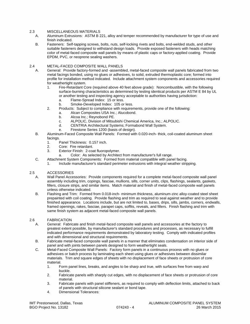
IMT Prestonwood, Dallas, Texas ALUMINUM COMPOSITE PANEL SYSTEM BGO Project No. 13182 074243 - 4 26 March 2015
2.3 MISCELLANEOUS MATERIALS A. Aluminum Extrusions: ASTM B 221, alloy and temper recommended by manufacturer for type of use and
finish indicated. B. Fasteners: Self-tapping screws, bolts, nuts, self-locking rivets and bolts, end-welded studs, and other
suitable fasteners designed to withstand design loads. Provide exposed fasteners with heads matching color of metal-faced composite wall panels by means of plastic caps or factory-applied coating. Provide EPDM, PVC, or neoprene sealing washers.
2.4 METAL-FACED COMPOSITE WALL PANELS A. General: Provide factory-formed and -assembled, metal-faced composite wall panels fabricated from two
metal facings bonded, using no glues or adhesives, to solid, extruded thermoplastic core; formed into profile for installation method indicated. Include attachment system components and accessories required for weathertight system. 1. Fire-Retardant Core (required above 40 feet above grade): Noncombustible, with the following
surface-burning characteristics as determined by testing identical products per ASTM E 84 by UL or another testing and inspecting agency acceptable to authorities having jurisdiction: a. Flame-Spread Index: 15 or less. b. Smoke-Developed Index: 105 or less.
2. Products: Subject to compliance with requirements, provide one of the following: a. Alcan Composites USA Inc.; Alucobond. b. Alcoa Inc.; Reynobond PE. c. ALPOLIC, Division of Mitsubishi Chemical America, Inc.; ALPOLIC. d. CENTRIA Architectural Systems; Formabond Wall System. e. Firestone Series 1200 (basis of design).
B. Aluminum-Faced Composite Wall Panels: Formed with 0.020-inch- thick, coil-coated aluminum sheet facings. 1. Panel Thickness: 0.157 inch. 2. Core: Fire retardant. 3. Exterior Finish: 2-coat fluoropolymer.
a. Color: As selected by Architect from manufacturer's full range. C. Attachment System Components: Formed from material compatible with panel facing.
1. Include manufacturer's standard perimeter extrusions with integral weather stripping.
2.5 ACCESSORIES A. Wall Panel Accessories: Provide components required for a complete metal-faced composite wall panel
assembly including trim, copings, fasciae, mullions, sills, corner units, clips, flashings, sealants, gaskets, fillers, closure strips, and similar items. Match material and finish of metal-faced composite wall panels unless otherwise indicated.
B. Flashing and Trim: Formed from 0.018-inch- minimum thickness, aluminum-zinc alloy-coated steel sheet prepainted with coil coating. Provide flashing and trim as required to seal against weather and to provide finished appearance. Locations include, but are not limited to, bases, drips, sills, jambs, corners, endwalls, framed openings, rakes, fasciae, parapet caps, soffits, reveals, and fillers. Finish flashing and trim with same finish system as adjacent metal-faced composite wall panels.
2.6 FABRICATION A. General: Fabricate and finish metal-faced composite wall panels and accessories at the factory to
greatest extent possible, by manufacturer's standard procedures and processes, as necessary to fulfill indicated performance requirements demonstrated by laboratory testing. Comply with indicated profiles and with dimensional and structural requirements.
B. Fabricate metal-faced composite wall panels in a manner that eliminates condensation on interior side of panel and with joints between panels designed to form weathertight seals.
C. Metal-Faced Composite Wall Panels: Factory form panels in a continuous process with no glues or adhesives or batch process by laminating each sheet using glues or adhesives between dissimilar materials. Trim and square edges of sheets with no displacement of face sheets or protrusion of core material. 1. Form panel lines, breaks, and angles to be sharp and true, with surfaces free from warp and
buckle. 2. Fabricate panels with sharply cut edges, with no displacement of face sheets or protrusion of core
material. 3. Fabricate panels with panel stiffeners, as required to comply with deflection limits, attached to back
of panels with structural silicone sealant or bond tape. 4. Dimensional Tolerances:

IMT Prestonwood, Dallas, Texas ALUMINUM COMPOSITE PANEL SYSTEM BGO Project No. 13182 074243 - 5 26 March 2015
a. Length: Plus 0.375 inch. b. Width: Plus 0.188 inch. c. Thickness: Plus or minus 0.008 inch. d. Panel Bow: 0.8 percent maximum of panel length or width. e. Squareness: 0.2 inch maximum.
D. Sheet Metal Accessories: Fabricate flashing and trim to comply with recommendations in SMACNA's "Architectural Sheet Metal Manual" that apply to design, dimensions, metal, and other characteristics of item indicated. 1. Form exposed sheet metal accessories that are without excessive oil canning, buckling, and tool
marks and that are true to line and levels indicated, with exposed edges folded back to form hems. 2. Seams for Aluminum: Fabricate nonmoving seams with flat-lock seams. Form seams and seal
with epoxy seam sealer. Rivet joints for additional strength. 3. Seams for Other Than Aluminum: Fabricate nonmoving seams in accessories with flat-lock seams.
Tin edges to be seamed, form seams, and solder. 4. Sealed Joints: Form non-expansion but movable joints in metal to accommodate elastomeric
sealant to comply with SMACNA standards. 5. Conceal fasteners and expansion provisions where possible. Exposed fasteners are not allowed
on faces of accessories exposed to view. 6. Fabricate cleats and attachment devices from same material as accessory being anchored or from
compatible, noncorrosive metal recommended by metal-faced composite wall panel manufacturer. a. Size: As recommended by SMACNA's "Architectural Sheet Metal Manual" or metal-faced
composite wall panel manufacturer for application, but not less than thickness of metal being secured.
2.7 GENERAL FINISH REQUIREMENTS A. Comply with NAAMM's "Metal Finishes Manual for Architectural and Metal Products" for recommendations
for applying and designating finishes. B. Protect mechanical and painted finishes on exposed surfaces from damage by applying a strippable,
temporary protective covering before shipping. C. Appearance of Finished Work: Noticeable variations in panels as determined by Architect are not
acceptable.
PART 3 - EXECUTION
3.1 EXAMINATION A. Examine substrates, areas, and conditions, with Installer present, for compliance with requirements for
installation tolerances, metal-faced composite wall panel supports, and other conditions affecting performance of the Work. 1. Examine wall framing to verify that girts, angles, channels, studs, and other structural panel support
members and anchorage have been installed within alignment tolerances required by metal-faced composite wall panel manufacturer.
2. Examine wall sheathing to verify that sheathing joints are supported by framing or blocking and that installation is within flatness tolerances required by metal-faced composite wall panel manufacturer.
3. Verify that weather-resistant membrane has been installed over sheathing or backing substrate to prevent air infiltration or water penetration.
B. Examine roughing-in for components and systems penetrating metal-faced composite wall panels to verify actual locations of penetrations relative to seam locations of panels before panel installation.
C. For the record, prepare written report, endorsed by Installer, listing conditions detrimental to performance of the Work, and issue to Architect as formal submittal.
D. Proceed with installation only after unsatisfactory conditions have been corrected.
3.2 PREPARATION A. Miscellaneous Framing: Install subgirts, base angles, sills, furring, and other miscellaneous wall panel
support members and anchorage according to ASTM C 754 and metal-faced composite wall panel manufacturer's written instructions.

IMT Prestonwood, Dallas, Texas ALUMINUM COMPOSITE PANEL SYSTEM BGO Project No. 13182 074243 - 6 26 March 2015
3.3 METAL-FACED COMPOSITE WALL PANEL INSTALLATION A. General: Install metal-faced composite wall panels according to manufacturer's written instructions in
orientation, sizes, and locations indicated on Drawings. Install panels perpendicular to girts and subgirts unless otherwise indicated. Anchor panels and other components of the Work securely in place, with provisions for thermal and structural movement. 1. Commence metal-faced composite wall panel installation and install minimum of 300 sq. ft. in
presence of factory-authorized representative. 2. Shim or otherwise plumb substrates receiving metal-faced composite wall panels. 3. Flash and seal metal-faced composite wall panels at perimeter of all openings. Do not begin
installation until weather barrier and flashings that will be concealed by panels are installed. 4. Install flashing and trim as metal-faced composite wall panel work proceeds. 5. Apply elastomeric sealant continuously between metal base channel (sill angle) and concrete, and
elsewhere as indicated or, if not indicated, as necessary for waterproofing. 6. Provide weathertight escutcheons for pipe and conduit penetrating exterior walls.
B. Fasteners: 1. Aluminum Wall Panels: Use aluminum or stainless-steel fasteners for surfaces exposed to the
exterior and aluminum or galvanized-steel fasteners for surfaces exposed to the interior. C. Metal Protection: Where dissimilar metals will contact each other or corrosive substrates, protect against
galvanic action as recommended by metal-faced composite wall panel manufacturer. D. Joint Sealers: Install gaskets, joint fillers, and sealants where indicated and where required for
weathertight performance of metal-faced composite wall panel assemblies. Provide types of gaskets, fillers, and sealants indicated or, if not indicated, types recommended by panel manufacturer. 1. Prepare joints and apply sealants to comply with requirements in Division 07 Section "Joint
Sealants." E. Attachment System Installation, General: Install attachment system required to support metal-faced
composite wall panels and to provide a complete weathertight wall system, including subgirts, perimeter extrusions, tracks, drainage channels, panel clips, and anchor channels. 1. Include attachment to supports, panel-to-panel joinery, panel-to-dissimilar-material joinery, and
panel-system joint seals. 2. Do not begin installation until weather barrier and flashings that will be concealed by composite
panels are installed. F. Rainscreen-Principle Installation: Provide manufacturer's standard pressure-equalized, rainscreen-
principle system with vertical channel that provides support and complete secondary drainage system, draining at base of wall. Notch vertical channel to receive support pins. Install vertical channels supported by channel brackets or adjuster angles and at locations, spacings, and with fasteners recommended by manufacturer. Attach wall panels by engaging horizontal support pins into notches in vertical channels and into flanges of wall panels. Leave horizontal and vertical joints with open reveal. 1. Install wall panels to allow individual panels to "free float" and be installed and removed without
disturbing adjacent panels. 2. Do not apply sealants to joints unless otherwise indicated on Drawings.
3.4 ACCESSORY INSTALLATION A. General: Install accessories with positive anchorage to building and weathertight mounting and provide for
thermal expansion. Coordinate installation with flashings and other components. 1. Install components required for a complete metal-faced composite wall panel assembly including
trim, copings, corners, seam covers, flashings, sealants, gaskets, fillers, closure strips, and similar items.
B. Flashing and Trim: Comply with performance requirements, manufacturer's written installation instructions, and SMACNA's "Architectural Sheet Metal Manual." Provide concealed fasteners where possible, and set units true to line and level as indicated. Install work with laps, joints, and seams that will be permanently watertight and weather resistant. 1. Install exposed flashing and trim that is without excessive oil canning, buckling, and tool marks and
that is true to line and levels indicated, with exposed edges folded back to form hems. Install sheet metal flashing and trim to fit substrates and to result in waterproof and weather-resistant performance.
2. Expansion Provisions: Provide for thermal expansion of exposed flashing and trim. Space movement joints at a maximum of 10 feet with no joints allowed within 24 inches of corner or intersection. Where lapped expansion provisions cannot be used or would not be sufficiently weather resistant and waterproof, form expansion joints of intermeshing hooked flanges, not less than 1 inch deep, filled with mastic sealant (concealed within joints).

IMT Prestonwood, Dallas, Texas ALUMINUM COMPOSITE PANEL SYSTEM BGO Project No. 13182 074243 - 7 26 March 2015
3.5 ERECTION TOLERANCES A. Installation Tolerances: Shim and align metal-faced composite wall panel units within installed tolerance of
1/4 inch in 20 feet, non-accumulative, on level, plumb, and location lines as indicated and within 1/8-inch offset of adjoining faces and of alignment of matching profiles.
3.6 FIELD QUALITY CONTROL A. Water-Spray Test: After completing the installation of 75-foot- by-2-story minimum area of metal-faced
composite wall panel assembly, test assembly for water penetration according to AAMA 501.2 in a 2-bay area directed by Architect.
B. Manufacturer's Field Service: Engage a factory-authorized service representative to inspect, test, and adjust completed metal-faced composite wall panel installation, including accessories.
C. Additional tests and inspections, at Contractor's expense, will be performed to determine compliance of replaced or additional work with specified requirements.
D. Prepare test and inspection reports.
3.7 CLEANING A. Remove temporary protective coverings and strippable films, if any, as metal-faced composite wall panels
are installed unless otherwise indicated in manufacturer's written installation instructions. On completion of metal-faced composite wall panel installation, clean finished surfaces as recommended by panel manufacturer. Maintain in a clean condition during construction.
B. After metal-faced composite wall panel installation, clear weep holes and drainage channels of obstructions, dirt, and sealant.
C. Replace metal-faced composite wall panels that have been damaged or have deteriorated beyond successful repair by finish touchup or similar minor repair procedures.
END OF SECTION

IMT Prestonwood, Dallas, Texas COMPOSITE FIBER CEMENT WALL PANELS BGO Project No. 13182 074342 - 1 26 March 2015
SECTION 074342
COMPOSITE FIBER CEMENT WALL PANELS
PART 1 - GENERAL
1.1 SECTION INCLUDES: A. Exterior, panelized fiber cement cladding system and accessories to complete a drained and back-
ventilated rainscreen. B. Interior fiber cement panelized cladding system and accessories.
1.2 REFERENCES A. American Architectural Manufacturers Association (AAMA):
1. AAMA 509-09 – Voluntary Test and Classification Method of Drained and Back Ventilated Rain Screen Wall Cladding Systems
B. ASTM International (ASTM): 1. ASTM C 518 - Standard Test Method for Steady-State Thermal Transmission Properties by Means
of the Heat Flow Meter Apparatus. 2. ASTM C 1185 - Standard Test Methods for Sampling and Testing Non-Asbestos Fiber Cement. 3. ASTM C 1186 – Standard Specification for Flat Fiber-Cement Sheets. 4. ASTM E 119 - Standard Test Methods for Fire Tests of Building Construction and Materials. 5. ASTM E 228 - Standard Test Method for Linear Thermal Expansion of Solid Materials with a
Vitreous Silica Dilatometer. 6. ASTM E 330 - Standard Test Method for Structural Performance of Exterior Windows, Curtain
Walls, and Doors by Uniform Static Air Pressure Difference. 7. ASTM E 331 - Standard Test Method for Water Penetration of Exterior Windows, Curtain Walls,
and Doors by Uniform Static Air Pressure Difference. 8. ASTM G 23 - Standard Practice for Operating Light-Exposure Apparatus (Carbon-Arc Type) with
and without Water for Exposure of Nonmetallic Materials, Replaced by G152 and G153. C. Florida Building Code - Test Protocol HVHZ
1. Testing Application Standard (TAS) 201, 202, 203 – Impact Test Procedures D. Underwriters Laboratories (UL):
1. UL 723/ASTM E-84 - Standard Test for Surface Burning Characteristics of Building Materials.
1.3 SUBMITTALS A. Submit under provisions of Section 013000. B. Product Data: Submit manufacturer’s product description, standard detail drawings relevant to the project,
storage and handling requirements, and installation instructions. C. Product Test Reports and Code Compliance: Documents demonstrating product compliance with local
building code, such as test reports or Evaluation Reports from qualified, independent testing agencies. D. Shop Drawings: Submit drawings, including plan, section, and elevation drawings, showing installation
details that demonstrate product layout, dimensions, finish colors, edge/termination conditions/treatments, compression and control joints, openings, and penetrations.
E. Samples: Submit samples of each product type proposed for use.
1.4 QUALITY ASSURANCE A. Manufacturer Qualifications:
1. All fiber cement panels specified in this section must be supplied by a manufacturer with a minimum of 10 years of experience in fabricating and supplying fiber cement cladding systems. a. Products covered under this section are to be manufactured in an ISO 9001 certified facility.
2. Provide technical and design support as needed regarding installation requirements and warranty compliance provisions.
B. Installer Qualifications: All products listed in this section are to be installed by a single installer trained by manufacturer or representative.
C. Mock-Up Wall: Provide a mock-up wall as evaluation tool for product and installation workmanship. D. Pre-Installation Meetings: Prior to beginning installation, conduct conference to verify and discuss
substrate conditions, manufacturer’s installation instructions and warranty requirements, and project requirements.
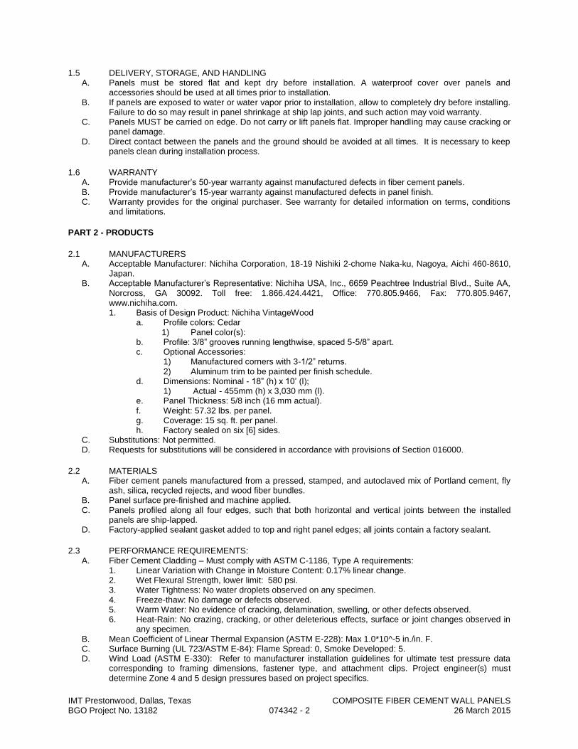
IMT Prestonwood, Dallas, Texas COMPOSITE FIBER CEMENT WALL PANELS BGO Project No. 13182 074342 - 2 26 March 2015
1.5 DELIVERY, STORAGE, AND HANDLING A. Panels must be stored flat and kept dry before installation. A waterproof cover over panels and
accessories should be used at all times prior to installation. B. If panels are exposed to water or water vapor prior to installation, allow to completely dry before installing.
Failure to do so may result in panel shrinkage at ship lap joints, and such action may void warranty. C. Panels MUST be carried on edge. Do not carry or lift panels flat. Improper handling may cause cracking or
panel damage. D. Direct contact between the panels and the ground should be avoided at all times. It is necessary to keep
panels clean during installation process.
1.6 WARRANTY A. Provide manufacturer’s 50-year warranty against manufactured defects in fiber cement panels. B. Provide manufacturer’s 15-year warranty against manufactured defects in panel finish. C. Warranty provides for the original purchaser. See warranty for detailed information on terms, conditions
and limitations.
PART 2 - PRODUCTS
2.1 MANUFACTURERS A. Acceptable Manufacturer: Nichiha Corporation, 18-19 Nishiki 2-chome Naka-ku, Nagoya, Aichi 460-8610,
Japan. B. Acceptable Manufacturer’s Representative: Nichiha USA, Inc., 6659 Peachtree Industrial Blvd., Suite AA,
Norcross, GA 30092. Toll free: 1.866.424.4421, Office: 770.805.9466, Fax: 770.805.9467, www.nichiha.com. 1. Basis of Design Product: Nichiha VintageWood
a. Profile colors: Cedar 1) Panel color(s):
b. Profile: 3/8” grooves running lengthwise, spaced 5-5/8” apart. c. Optional Accessories:
1) Manufactured corners with 3-1/2” returns. 2) Aluminum trim to be painted per finish schedule.
d. Dimensions: Nominal - 18” (h) x 10’ (l); 1) Actual - 455mm (h) x 3,030 mm (l).
e. Panel Thickness: 5/8 inch (16 mm actual). f. Weight: 57.32 lbs. per panel. g. Coverage: 15 sq. ft. per panel. h. Factory sealed on six [6] sides.
C. Substitutions: Not permitted. D. Requests for substitutions will be considered in accordance with provisions of Section 016000.
2.2 MATERIALS A. Fiber cement panels manufactured from a pressed, stamped, and autoclaved mix of Portland cement, fly
ash, silica, recycled rejects, and wood fiber bundles. B. Panel surface pre-finished and machine applied. C. Panels profiled along all four edges, such that both horizontal and vertical joints between the installed
panels are ship-lapped. D. Factory-applied sealant gasket added to top and right panel edges; all joints contain a factory sealant.
2.3 PERFORMANCE REQUIREMENTS: A. Fiber Cement Cladding – Must comply with ASTM C-1186, Type A requirements:
1. Linear Variation with Change in Moisture Content: 0.17% linear change. 2. Wet Flexural Strength, lower limit: 580 psi. 3. Water Tightness: No water droplets observed on any specimen. 4. Freeze-thaw: No damage or defects observed. 5. Warm Water: No evidence of cracking, delamination, swelling, or other defects observed. 6. Heat-Rain: No crazing, cracking, or other deleterious effects, surface or joint changes observed in
any specimen. B. Mean Coefficient of Linear Thermal Expansion (ASTM E-228): Max 1.0*10^-5 in./in. F. C. Surface Burning (UL 723/ASTM E-84): Flame Spread: 0, Smoke Developed: 5. D. Wind Load (ASTM E-330): Refer to manufacturer installation guidelines for ultimate test pressure data
corresponding to framing dimensions, fastener type, and attachment clips. Project engineer(s) must determine Zone 4 and 5 design pressures based on project specifics.

IMT Prestonwood, Dallas, Texas COMPOSITE FIBER CEMENT WALL PANELS BGO Project No. 13182 074342 - 3 26 March 2015
1. Minimum lateral deflection: L/120. E. Water Penetration (ASTM E-331): No water leakage observed into wall cavity. F. Weather Resistant (ASTM G-23): No cracking, checking, crazing, erosion, or other detrimental effects
observed. G. Steady-State Heat Flux and Thermal Transmission Properties Test (ASTM C-518): thermal resistance R
Value of 1.23 F. H. Fire Resistant (ASTM E-119): The wall assembly must successfully endure 60-minute fire exposure
without developing excessive unexposed surface temperature or allowing flaming on the unexposed side of the assembly.
I. Drained and Back Ventilated Rainscreen (AAMA 509-09): System must pass all component tests. J. Florida Building Code - Test Protocol HVHZ (TAS 201, 202, 203): Passed.
2.4 INSTALLATION COMPONENTS A. Steel Clip System:
1. Starter Track: a. Horizontal Panel Installations - FA 100B – 10’ (l) galvalume. b. Vertical Panel Installations (10’ panels only) – FA 300T – 6’6” (l) galvalume.
2. Panel Clips: JE 550 (5mm rainscreen), JE 710 (10mm rainscreen) – 400 series stainless steel. 3. Joint Clips: Short – JEJ 555; Long – JEL 551 (5mm), JEL 552 (10mm) - 400 series stainless steel. 4. Corner Clips (for use with manufactured corners): JE 550C (5mm) - 400 series stainless steel. 5. Single Flange Sealant Backer – FHK 1110 (5mm), FHK 1017 (10mm) – 6.5’ (l) fluorine coated
galvalume. 6. Double Flange Sealant Backer – FH 1010 (5mm), FH 1020 (10mm) – 10’ (l) fluorine coated
galvalume. 7. Corrugated Shim – FS 1005 (5mm), FS 1010 (10mm) – 4’ (l).
B. Aluminum Trim (optional): Paint as specified in finish schedule. C. Fasteners: Corrosion resistant fasteners, such as hot-dipped galvanized screws appropriate to local
building codes and practices must be used. Use Stainless Steel fasteners in high humidity and high-moisture regions. Panel manufacturer is not liable for corrosion resistance of fasteners. Do not use aluminum fasteners, staples, or fasteners that are not rated or designed for intended use. See manufacturer’s instructions for appropriate fasteners for construction method used.
D. Flashing: Flash all areas specified in manufacturer’s instructions. Do not use raw aluminum flashing. Flashing must be galvanized, anodized, or PVC coated.
E. Sealant: Sealant shall be polyurethane, or hybrid, and comply with ASTM C920.
PART 3 - EXECUTION
3.1 EXAMINATION A. Verification of Conditions:
1. Fiber cement panels can be installed over braced wood, steel studs and sheathing including plywood, OSB, plastic foam or fiberboard sheathing. Fiber cement panels can also be installed over Structural Insulated Panels (SIP’s), Concrete Masonry Units (CMU’s) and Concrete Block Structures (CBS’s) with furring strips, and Pre-Engineered Metal Construction.
2. Allowable stud spacing: See manufacturer’s installation instructions for details. 3. A weather resistive barrier is required when installing fiber cement panels. Use an approved
weather resistive barrier (WRB) as defined by the 2012 IRC. Refer to local building codes. 4. Appropriate metal flashing should be used to prevent moisture penetration around all doors,
windows, wall bottoms, material transitions and penetrations. Refer to local building codes for best practices.
B. Examine site to ensure substrate conditions are within specification for proper installation. C. Do not begin installation until unacceptable conditions have been corrected. D. Do not install panels or components that appear to be damaged or defective. Do not install wet panels.
3.2 INSTALLATION A. General: Install products in accordance with the latest installation guidelines of the manufacturer and all
applicable building codes and other laws, rules, regulations and ordinances. Review all manufacturer installation, maintenance instructions, and other applicable documents before installation. 1. Consult with your local dealer or Nichiha Technical Department before installing any Nichiha fiber
cement product on a building higher than 45 feet or three stories. Special installation conditions may be required.
B. Panel Cutting
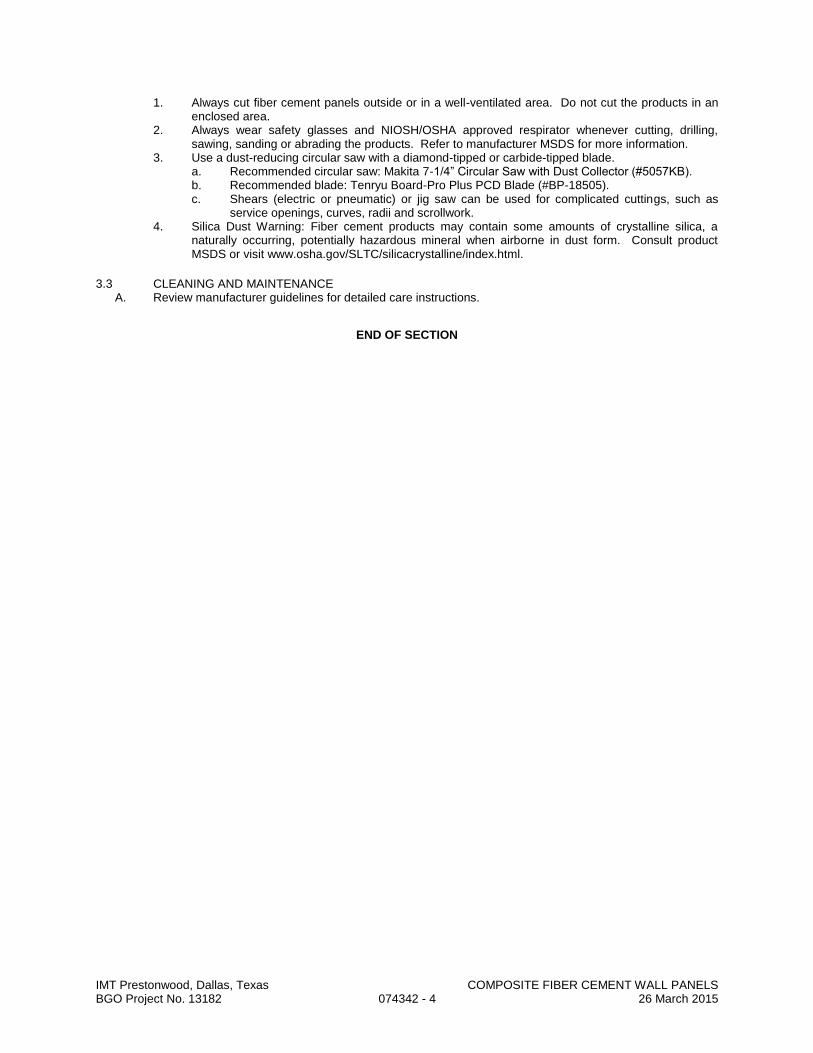
IMT Prestonwood, Dallas, Texas COMPOSITE FIBER CEMENT WALL PANELS BGO Project No. 13182 074342 - 4 26 March 2015
1. Always cut fiber cement panels outside or in a well-ventilated area. Do not cut the products in an enclosed area.
2. Always wear safety glasses and NIOSH/OSHA approved respirator whenever cutting, drilling, sawing, sanding or abrading the products. Refer to manufacturer MSDS for more information.
3. Use a dust-reducing circular saw with a diamond-tipped or carbide-tipped blade. a. Recommended circular saw: Makita 7-1/4” Circular Saw with Dust Collector (#5057KB). b. Recommended blade: Tenryu Board-Pro Plus PCD Blade (#BP-18505). c. Shears (electric or pneumatic) or jig saw can be used for complicated cuttings, such as
service openings, curves, radii and scrollwork. 4. Silica Dust Warning: Fiber cement products may contain some amounts of crystalline silica, a
naturally occurring, potentially hazardous mineral when airborne in dust form. Consult product MSDS or visit www.osha.gov/SLTC/silicacrystalline/index.html.
3.3 CLEANING AND MAINTENANCE A. Review manufacturer guidelines for detailed care instructions.
END OF SECTION

IMT Prestonwood, Dallas, Texas FIBER CEMENT SIDING AND SOFFITS BGO Project No. 13182 074646 - 1 26 March 2015
SECTION 074646
FIBER CEMENT SIDING AND SOFFITS
PART 1 - GENERAL
1.1 SECTION INCLUDES A. Wood-fiber cement siding, soffits, and trim.
1.2 SUBMITTALS A. See Section 013000 - Administrative Requirements, for submittal procedures. B. Product Data: Manufacturer's data sheets on each product to be used, including:
1. Manufacturer's requirements for related materials to be installed by others. 2. Preparation instructions and recommendations. 3. Storage and handling requirements and recommendations. 4. Installation methods, including nail patterns.
C. Warranty: Submit copy of manufacturer’s warranty, made out in Owner’s name, showing that it has been registered with manufacturer.
1.3 QUALITY ASSURANCE A. Installer Qualifications: Company specializing in performing work of the type specified in this section with
minimum 3 years of experience.
1.4 DELIVERY, STORAGE, AND HANDLING A. Store products under waterproof cover and elevated above grade, on a flat surface.
PART 2 - PRODUCTS
2.1 PRODUCTS
A. Acceptable Manufacturers: 1. James Hardie Building Products, Inc: www.jameshardie.com. 2. Nichiha USA, Inc: www.nichiha.com 3. Cemplank; cemplank.com
B. Fiber Reinforced Cement Lap Siding: Individual horizontal boards made of cement and cellulose fiber formed under high pressure with integral surface texture, complying with ASTM C 1186 Type A Grade II; with machined edges, for nail attachment. 1. Style: Standard lap style. 2. Texture: Simulated cedar grain. 3. Length: 12 ft, nominal. 4. Width (Height): 5-1/4 inches or as otherwise indicated on Drawings. 5. Thickness: 5/16 inch, nominal. 6. Finish: Factory applied primer. 7. Warranty: 50 year limited; transferable.
C. Fiber Reinforced Cement Sheet Siding: Cement fiber reinforced lap siding, finish as selected by Architect; 4 x 8 x 5/16 inch thick; having the following ASTM E 84 fire test performance: Flame Spread 0, Fuel Contribution 0, Smoke Development 5. 1. Acceptable Products:
a. Hardipanel by James Hardie Building Products. D. Fiber Reinforced Cement Soffit Panels: Panels made of cement and cellulose fiber formed under high
pressure with integral surface texture, complying with ASTM C 1186 Type A Grade II; with machined edges, for nail attachment. 1. Texture: Simulated cedar grain. 2. Length: 96 inches, nominal. 3. Width: 48 inches. 4. Thickness: 5/16 inch, nominal. 5. Finish: Factory applied primer. 6. Manufacturer: Same as siding. 7. Perforations: Manufacturer’s standard for attic ventilation.
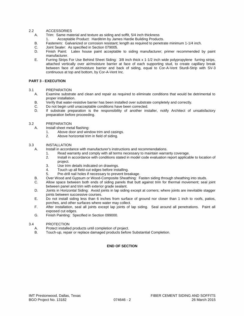
IMT Prestonwood, Dallas, Texas FIBER CEMENT SIDING AND SOFFITS BGO Project No. 13182 074646 - 2 26 March 2015
2.2 ACCESSORIES A. Trim: Same material and texture as siding and soffit, 5/4 inch thickness
1. Acceptable Product: Harditrim by James Hardie Building Products. B. Fasteners: Galvanized or corrosion resistant; length as required to penetrate minimum 1-1/4 inch. C. Joint Sealer: As specified in Section 079005. D. Finish Paint: Latex house paint acceptable to siding manufacturer; primer recommended by paint
manufacturer. E. Furring Strips For Use Behind Sheet Siding: 3/8 inch thick x 1-1/2 inch wide polypropylene furring strips,
attached vertically over air/moisture barrier at face of each supporting stud, to create capillary break between face of air/moisture barrier and back of siding, equal to Cor-A-Vent Sturdi-Strip with SV-3 continuous at top and bottom, by Cor-A-Vent Inc.
PART 3 - EXECUTION
3.1 PREPARATION A. Examine substrate and clean and repair as required to eliminate conditions that would be detrimental to
proper installation. B. Verify that water-resistive barrier has been installed over substrate completely and correctly. C. Do not begin until unacceptable conditions have been corrected. D. If substrate preparation is the responsibility of another installer, notify Architect of unsatisfactory
preparation before proceeding.
3.2 PREPARATION A. Install sheet metal flashing:
1. Above door and window trim and casings. 2. Above horizontal trim in field of siding.
3.3 INSTALLATION A. Install in accordance with manufacturer's instructions and recommendations.
1. Read warranty and comply with all terms necessary to maintain warranty coverage. 2. Install in accordance with conditions stated in model code evaluation report applicable to location of
project. 3. Use trim details indicated on drawings. 4. Touch up all field-cut edges before installing. 5. Pre-drill nail holes if necessary to prevent breakage.
B. Over Wood and Gypsum or Wood-Composite Sheathing: Fasten siding through sheathing into studs. C. Allow space between both ends of siding panels that butt against trim for thermal movement; seal joint
between panel and trim with exterior grade sealant. D. Joints in Horizontal Siding: Avoid joints in lap siding except at corners; where joints are inevitable stagger
joints between successive courses. E. Do not install siding less than 6 inches from surface of ground nor closer than 1 inch to roofs, patios,
porches, and other surfaces where water may collect. F. After installation, seal all joints except lap joints of lap siding. Seal around all penetrations. Paint all
exposed cut edges. G. Finish Painting: Specified in Section 099000.
3.4 PROTECTION A. Protect installed products until completion of project. B. Touch-up, repair or replace damaged products before Substantial Completion.
END OF SECTION

SECTION 075200
MODIFIED BITUMINOUS MEMBRANE ROOFING PART 1 GENERAL
1.1 SECTION INCLUDES
A. Modified bituminous roofing membrane, conventional application. B. Insulation, flat and tapered. C. Insulation cover board. D. Base flashings. E. Pavers at occupied areas.
1.2 DESIGN CRITERIA
A. General: Installed roofing membrane system shall remain watertight; and resist specified wind uplift pressures, thermally induced movement, and exposure to weather without failure.
B. Material Compatibility: Roofing materials shall be compatible with one another under conditions of service and application required, as demonstrated by roofing system manufacturer based on testing and field experience.
C. EPA Energy Star: 1. Roofing membrane shall achieve an initial reflectance of greater than 0.65 and a three year aged
reflectance of greater than 0.50. 1.3 SUBMITTALS
A. See Section 013000 - Administrative Requirements, for submittal procedures. B. Product Data: Provide manufacturer's catalog data for membrane and bitumen materials, base
flashing materials, insulation, and surfacing. C. Shop Drawings: Indicate joint or termination detail conditions, conditions of interface with other
materials, setting plan for tapered insulation, and mechanical fastener layout. D. Samples: Submit two samples 12x12 inches in size illustrating granule surfaced sheet, colored coated
sheet, and insulation. E. Manufacturer's qualification data. F. Installer's qualification data. G. Manufacturer's Installation Instructions: Indicate special procedures. H. Manufacturer's Certificate: Certify that products meet or exceed specified requirements. I. Manufacturer's Field Reports: Indicate procedures followed. J. Warranty: Submit manufacturer warranty and ensure forms have been completed in Owner's name
and registered with manufacturer. 1.4 QUALITY ASSURANCE
A. Perform work in accordance with NRCA Roofing and Waterproofing Manual and manufacturer's instructions.
B. Manufacturer Qualifications: Company specializing in manufacturing the products specified in this section with minimum three years of documented experience.
C. Installer Qualifications: Company specializing in performing the work of this section with minimum 5 years’ experience and approved by manufacturer.
1.5 PRE-INSTALLATION MEETING
A. Convene one week before starting work of this section. B. Review preparation and installation procedures and coordinating and scheduling required with related
work. 1.6 DELIVERY, STORAGE, AND PROTECTION
A. Deliver products in manufacturer's original containers, dry, undamaged, with seals and labels intact. B. Store products in weather protected environment, clear of ground and moisture; ballast materials may
be stored outdoors. C. Protect foam insulation from direct exposure to sunlight. D. Any materials that are found to be damaged or stored in any manner other than as stated above shall be
marked and automatically rejected and shall be removed and replaced at Contractor's expense.
IMT Prestonwood, Dallas, MODIFIED BITUMINOUS MEMBRANE ROOFING Texas BGO Project No. 13182 075200 - 1 14 January 2015
1.7 PROJECT CONDITIONS A. Coordinate the work with installation of associated flashings and counter flashings installed by other
sections as the work of this section proceeds. B. Do not apply roofing membrane when environmental conditions are outside the ranges recommended
by manufacturer. C. Do not apply roofing membrane during unsuitable weather. D. Do not apply roofing membrane when ambient temperature is below 40 degrees F. E. Do not apply roofing membrane to damp or frozen deck surface or when precipitation is expected or
occurring. F. Do not expose materials vulnerable to water or sun damage in quantities greater than can be
weatherproofed the same day.
1.8 WARRANTY A. See Section 017800 - Closeout Submittals, for additional warranty requirements. B. The Contractor will furnish to the Owner a five (5) year written guarantee covering workmanship. This
guarantee shall cover materials, as well as agreeing to make prompt repairs to any and all leaks when reported within twenty-four (24) hours. The guarantee shall be unlimited as to the cost of its coverage. It shall also be assignable if there is a change of ownership of the property during its term.
C. Correct defective Work within a five year period after Date of Substantial Completion. D. The Contractor shall agree, in writing, to make an inspection with the Owner's Representative,
approximately two months prior to the expiration of the five (5) guarantee. Contractor shall furnish Owner with written notice of such inspection. Contractor shall provide safe access to all roof areas and include all associated costs for the inspection in Contractor’s bid. All deficiencies noted at this inspection, or at any time prior to this inspection, shall be repaired by the Contractor at no cost to the Owner. Should Contractor fail to notify Owner of the inspection, the inspection shall occur at any time after the expiration of the guarantee as requested by Owner. The deficiencies shall include, but not be limited to slippage, shrinkage, blisters, bare spots, fishmouths, deteriorated coatings and splits.
E. Provide 20 year NDL manufacturer's material and labor warranty to cover failure to prevent penetration of water.
PART 2 PRODUCTS
2.2 MANUFACTURERS
A. Membrane Materials: 1. GAF Materials Corporation: www.gaf.com. 2. Firestone Building Products Co: www.firestonebpco.com. 3. Siplast: www.siplast.com. 4. Tamko Roofing Products, Inc.: www.tamko.com. 5. Substitutions: See Section 016000 - Product Requirements.
B. Roof Insulation: 1. E’NERG’Y 3 by Johns Manville: www.jm.com 2. Multi-Max FA-3 by Rmax, Inc.: www.rmax.com 3. EnergyGuard Polyiso Roof Insulation: www.gaf.com. 4. ACFoam III: www.atlasroofing.com. 5. Substitutions: See Section 016000 - Product Requirements.
C. Cover Board: 1. Securock Roof Board by USG Corporation. 2. Substitutions: See Section 016000 - Product Requirements.
2.3 ROOFING - CONVENTIONAL APPLICATION
A. Modified Bituminous Roofing: Two-ply membrane, with insulation. B. Roofing Assembly Requirements:
1. External Fire Exposure Classification: ASTM E 108 Class A, UL, Warnock Hersey, or A listed. 2. Wind Resistance Classification: Factory Mutual I-90, in accordance with FM DS 1-28.
IMT Prestonwood, Dallas, MODIFIED BITUMINOUS MEMBRANE ROOFING Texas BGO Project No. 13182 075200 - 2 14 January 2015

2.4 MEMBRANE AND SHEET MATERIALS A. Membrane: Polymer modified asphalt, reinforced with non-woven fabric; granule surfaced; with the
following characteristics: 1. Minimum Quality: ASTM D 6163 Type I; styrene-butadiene-styrene (SBS) modified, glass fiber
reinforced. 2. Thickness: 130 mils. 3. Average Weight: 90 lb/sq ft. 4. Surface Color: White granules of type required to meet LEED reflectance requirements.
B. Flexible Flashing Material: Same material as membrane. 2.5 BITUMINOUS MATERIALS
A. Bitumen: Asphalt, ASTM D 312 Type IV; for adhering insulation, use Type III. B. Primer: ASTM D 41, asphalt type. C. Roof Cement: ASTM D 4586, Type II.
2.6 INSULATION
A. Base Layer: Rigid, closed cell polyisocyanurate foam core bonded to heavy duty glass fiber mat facers, with the following characteristics: 1. Board Size: 4 ft. X 4 ft. maximum. 2. Tapered Board: Slope as indicated; minimum thickness 1/4 inch; fabricate of fewest layers
possible. 3. Standard: ASTM C1289-01, Type II. 4. Thermal Resistance: Minimum requirement of the Energy Code. 5. Substitutions: See Section 016000 - Product Requirements.
B. Cover Board: Non-structural glass mat facings front and back embedded into a water-
resistant gypsum core, with the following characteristics: 1. Thickness: 1/4 in. 2. Board Size: 4 ft. X 4 ft. maximum. 3. Standard:
a. ASTM E 84 b. ASTM C 473 c. ASTM D 3273 d. Class A UL 790
4. Substitutions: See Section 016000 - Product Requirements. 2.7 SURFACING MATERIALS - CONVENTIONAL APPLICATION
A. Walkway Pads: Bitumen-impregnated mineral fiber boards with granular surfaces, compatible with roofing materials. 1. Finish: Match roof.
B. Pavers at Occupied Areas: Firestone SkyPaver Composite Roof Pavers. Provide complete with grid plates and drainage sheet.
2.8 ACCESSORIES
A. Prefabricated Roofing Expansion Joint Flashing: As specified in Section 077100. B. Cant and Edge Strips: Asphalt-impregnated wood fiberboard, compatible with roofing materials; cants
formed to 45 degree angle. C. Insulation Fasteners: Appropriate for purpose intended and approved by roofing manufacturer. D. Strip Reglet Devices: Galvanized steel, maximum possible lengths per location, with attachment
flanges. E. Sealants: As recommended by membrane manufacturer.
PART 3 EXECUTION
3.1 EXAMINATION
A. Verify that surfaces and site conditions are ready to receive work. B. Verify deck is supported and secure. C. Verify deck is clean and smooth, flat, free of depressions, waves, or projections, properly sloped and
suitable for installation of roof system. D. Verify deck surfaces are dry and free of snow or ice.
IMT Prestonwood, Dallas, MODIFIED BITUMINOUS MEMBRANE ROOFING Texas BGO Project No. 13182 075200 - 3 14 January 2015

E. Verify that roof openings, curbs, and penetrations through roof are solidly set, and cant strips are in place.
3.2 INSULATION INSTALLATION - CONVENTIONAL APPLICATION
A. Install insulation boards with long joints in a continuous straight line with end joints staggered between rows, abutting edges and ends between boards. Fill gaps exceeding 1/4 inch with like material.
B. Attachment of Insulation: 1. Mechanically fasten first layer of insulation to deck in accordance with roofing manufacturer's
instructions and Factory Mutual requirements. 2. Embed insulation cover board into flood coat mopping of hot bitumen in accordance with
roofing and insulation manufacturers' instructions. C. Place tapered insulation to the required slope pattern in accordance with manufacturer's instructions. D. On metal deck, place boards parallel to flutes with insulation board edges bearing on deck flutes. E. Lay boards with edges in moderate contact without forcing. Cut insulation to fit neatly to
perimeter blocking and around penetrations through roof. F. At roof drains, use factory-tapered boards to slope down to roof drains over a distance of 18 inches. G. Do not apply more insulation than can be covered with membrane in same day.
3.3 MEMBRANE APPLICATION, GENERAL
A. An aesthetically pleasing, overall appearance of the finished roof application is a standard requirement for this project. Make necessary preparations, utilize recommended application techniques, apply the specified materials (i.e. granules, metallic powder, etc.), and exercise care in ensuring that the finished application is acceptable to the Owner.
B. Apply membrane in accordance with manufacturer's instructions. C. Start installation of roofing membrane in presence of roofing system manufacturer's technical personnel. D. Where roof slope exceeds 1/2 inch per 12 inches (1:24, contact the membrane manufacturer for
installation instructions regarding installation direction and backnailing E. Apply membrane; lap and seal edges and ends permanently waterproof. F. Apply smooth, free from air pockets, wrinkles, fish-mouths, or tears. Ensure full bond of membrane to
substrate. G. At end of day's operation, install waterproof cut-off. Remove cut-off before resuming roofing. H. At intersections with vertical surfaces:
1. Extend membrane over cant strips and up a minimum of 8 inches onto vertical surfaces. 2. Apply flexible flashing over membrane. 3. Secure flashing to nailing strips at 4 inches on center. 4. Insert base flashing into reglets and secure.
I. At gravel stops, extend membrane and base sheet under gravel stop and to the outside face of the wall.
J. Around roof penetrations, mop in and seal flanges and flashings with flexible flashing. K. Install roofing expansion joints where indicated. Make joints watertight. L. Asphalt Heating: Heat roofing asphalt to temperature recommended by roofing manufacturer to flux
modified membrane. Do not exceed roofing asphalt manufacturer's recommended temperature limits during roofing asphalt heating. Discard roofing asphalt maintained at a temperature exceeding finished blowing temperature for more than 4 hours.
M. Substrate-Joint Penetrations: Prevent roofing asphalt from penetrating substrate joints, entering building, or damaging roofing system components or adjacent building construction. 1. Install prefabricated joint components in accordance with manufacturer's instructions.
N. Coordinate installation of roof drains and sumps and related flashings. 3.4 MEMBRANE APPLICATION
A. Install one modified bituminous roofing membrane sheet and cap sheet according to roofing manufacturer's written instructions, starting at low point of roofing system. Extend roofing membrane sheets over and terminate beyond cants, installing as follows: 1. Adhere to substrate in a solid mopping of hot roofing asphalt applied at temperatures
recommended by roofing system manufacturer. 2. Adhere to substrate in cold-applied adhesive according to roofing system manufacturer’s
instruction. 3. Unroll roofing membrane sheets and allow them to relax for minimum time period required by
manufacturer.
IMT Prestonwood, Dallas, MODIFIED BITUMINOUS MEMBRANE ROOFING Texas BGO Project No. 13182 075200 - 4 14 January 2015

B. Laps: Accurately align roofing membrane sheets, without stretching, and maintain uniform side and end laps. Stagger end laps. Completely bond and seal laps, leaving no voids. 1. Repair tears and voids in laps and lapped seams not completely sealed. 2. Apply roofing granules to cover exuded bead at laps while bead is hot.
3.5 FLASHING AND STRIPPING INSTALLATION
A. Install base flashing over cant strips and other sloping and vertical surfaces, at roof edges, and at penetrations through roof, and secure to substrates according to roofing system manufacturer's written instructions and as follows: 1. Prime substrates with asphalt primer if required by roofing system manufacturer. 2. Backer Sheet Application: Mechanically fasten backer sheet to walls or parapets. Adhere backer
sheet over roofing membrane at cants in a solid mopping of hot roofing asphalt. 3. Backer Sheet Application: Install backer sheet and adhere to substrate in a solid mopping of hot
roofing asphalt. 4. Backer Sheet Application: Install backer sheet and adhere to substrate in approved adhesive
applied at rate required by roofing system manufacturer. 5. Flashing Sheet Application: Adhere flashing sheet to substrate in a solid mopping of hot roofing
asphalt applied at EVT. Apply hot roofing asphalt to back of flashing sheet if recommended by roofing system manufacturer.
6. Flashing Sheet Application: Adhere flashing sheet to substrate in approved adhesive applied at rate required by roofing system manufacturer.
7. Flashing Sheet Application: Adhere flashing sheet to substrate in approved asphalt roofing cement; apply cement at rate required by roofing system manufacturer.
B. Extend base flashing up walls or parapets a minimum of 8 inches above roofing membrane and 4 inches
onto field of roofing membrane.
C. Mechanically fasten top of base flashing securely at terminations and perimeter of roofing. 1. Seal top termination of base flashing with a strip of glass-fiber fabric set in approved flashing
cement.
D. Proceed with installation only after unsatisfactory conditions have been corrected. 3.6 SURFACING - CONVENTIONAL APPLICATION
A. Install walkway pads by setting in hot bitumen. Set joints 6 inches apart. B. Install pavers at occupied areas in accordance with manufacturer’s instructions.
3.7 FIELD QUALITY CONTROL
A. See Section 014000 - Quality Requirements, for general requirements for field quality control and inspection.
B. Require site attendance of roofing and insulation material manufacturers daily during installation of the Work.
3.8 CLEANING A. Remove bituminous markings from finished surfaces. B. In areas where finished surfaces are soiled by bitumen or other source of soiling caused by work of this
section, consult manufacturer of surfaces for cleaning advice and conform to their documented instructions.
C. Repair or replace defaced or damaged finishes caused by work of this section. 3.9 PROTECTION OF FINISHED WORK
A. Protect installed roofing and flashings from construction operations. B. Where traffic must continue over finished roof membrane, protect surfaces using durable materials. C. Repair or replace defaced or disfigured finishes caused by work during the course of this project.
END OF SECTION
IMT Prestonwood, Dallas, MODIFIED BITUMINOUS MEMBRANE ROOFING Texas BGO Project No. 13182 075200 - 5 14 January 2015
SECTION 076200
SHEET METAL FLASHING AND TRIM
PART 1 GENERAL 1.1 SECTION INCLUDES
A. Fabricated sheet metal items, including flashings, counter flashings, and other items indicated in Schedule.
B. Reglets and accessories. C. Conductor heads. D. Overflow scuppers. E. Downspouts.
1.2 ADMINISTRATIVE REQUIREMENTS
A. Pre-installation Meeting: Convene one week before starting work of this section. 1.3 SUBMITTALS
A. See Section 013000 - Administrative Requirements, for submittal procedures. B. Shop Drawings: Indicate material profile, jointing pattern, jointing details, fastening methods, flashings,
terminations, and installation details. 1.4 QUALITY ASSURANCE
A. Perform work in accordance with SMACNA Architectural Sheet Metal Manual requirements and standard details, except as otherwise indicated.
B. Fabricator and Installer Qualifications: Company specializing in sheet metal work with three years of documented experience.
1.5 DELIVERY, STORAGE, AND HANDLING
A. Stack material to prevent twisting, bending, and abrasion, and to provide ventilation. Slope metal sheets to ensure drainage.
B. Prevent contact with materials that could cause discoloration or staining. 1.6 WARRANTY
A. Provide five year water tightness warranty against leaks through sheet metal flashing and at terminations.
PART 2 PRODUCTS
2.1 SHEET MATERIALS
A. Pre-Finished Galvanized Steel: ASTM A653/A653M, with G90/Z275 zinc coating; minimum 0.02 inch thick base metal, shop pre-coated with PVDF coating. 1. PVDF (Polyvinylidene Fluoride) Coating: Superior Performance Organic Finish, AAMA 2605;
multiple coat, thermally cured fluoropolymer finish system. B. Pre-Finished Aluminum: ASTM B209 (ASTM B209M); 0.032 inch thick; plain finish shop pre-coated
with modified silicone coating. 1. Modified Silicone Polyester Coating: Pigmented Organic Coating System, AAMA 2603; baked
enamel finish system. 2. Fluoropolymer Coating: High Performance Organic Finish, AAMA 2604; multiple coat,
thermally cured fluoropolymer finish system. 3. Color: To match approved sample.
2.2 ACCESSORIES
A. Fasteners: Galvanized steel, with soft neoprene washers. B. Underlayment: ASTM D226, organic roofing felt, Type I ("No. 15"). C. Primer: Zinc chromate type. D. Protective Backing Paint: Zinc molybdate alkyd. E. Sealant: Type S-GP specified in Section 079005. F. Plastic Cement: ASTM D4586, Type I. G. Reglets: Surface mounted type, galvanized steel.
IMT Prestonwood, Dallas, MODIFIED BITUMINOUS MEMBRANE ROOFING Texas BGO Project No. 13182 076200 - 1 14 January 2015
H. Lead Flashings: ASTM B 29-79, four (4) lb. sheet lead. 1. Flanges: Minimum 4 in. 2. Throat part of jack shall be of sufficient height to extend beyond height of existing pipe and
turn inside pipes a minimum of one inch. I. Paint – Roof Accessories:
1. Protective Enamel, color to match roof membrane. 2. Source: Rust-Oleum or manufacturer’s Roof Accessory Paint.
2.3 CONDUCTOR HEADS & OVERFLOWS
A. Install conductor heads where shown on the drawings. Install overflow scuppers at parapet walls where shown on the drawings. 1. 24 ga. pre-finished sheet metal. Lap joints one in. rivet and seal. 2. Size for maximum drainage per SMACNA Appendix G recommendations. 3. Fabricate conductor heads and overflow scuppers as drawn. 4. Outlet tubes for conductor heads shall have a minimum length of 4 in. 5. Cut overflow openings in each conductor head. These shall be in addition to the specified
overflow scuppers at parapet walls
2.4 DOWNSPOUTS A. Install downspouts at all conductor heads.
1. 24 ga. pre-finished sheet metal. 2. Size in accordance with SMACNA. 3. Install straps at top, bottom, and 10 ft. O.C. maximum. 4. Connect to underground drainage; otherwise provide concrete splash blocks under each
downspout.
2.5 FABRICATION A. Form sections true to shape, accurate in size, square, and free from distortion or defects. B. Form pieces in longest possible lengths. C. Hem exposed edges on underside 1/2 inch; miter and seam corners. D. Form material with flat lock seams, except where otherwise indicated. At moving joints, use sealed
lapped, bayonet-type or interlocking hooked seams. E. Fabricate corners from one piece with minimum 18 inch long legs; seam for rigidity, seal with sealant. F. Fabricate vertical faces with bottom edge formed outward 1/4 inch and hemmed to form drip.
PART 3 EXECUTION
3.1 EXAMINATION
A. Verify roof openings, curbs, pipes, sleeves, ducts, and vents through roof are solidly set, reglets in place, and nailing strips located.
B. Verify roofing termination and base flashings are in place, sealed, and secure. 3.2 PREPARATION
A. Install starter and edge strips, and cleats before starting installation. B. Install surface mounted reglets true to lines and levels. Seal top of reglets with sealant. C. Back paint concealed metal surfaces with protective backing paint to a minimum dry film thickness of
15 mil. D. Prime all metal flanges (jacks, edge metal, lead flashings, etc.) with a uniform coating of asphalt
primer. 3.3 INSTALLATION
A. Conform to drawing details. B. Secure flashings in place using concealed fasteners. Use exposed fasteners only where permitted. C. Apply plastic cement compound between metal flashings and felt flashings. D. Fit flashings tight in place. Make corners square, surfaces true and straight in planes, and
lines accurate to profiles. E. Seal metal joints watertight. F. Edge Sealant: Apply a smooth continuous bead of compatible sealant at the exposed finish ply edge
transition of the membrane to metal flashings incorporated into the roof system. IMT Prestonwood, Dallas, MODIFIED BITUMINOUS MEMBRANE ROOFING Texas BGO Project No. 13182 076200 - 2 14 January 2015

3.4 PAINTING OF ROOF ACCESSORIES A. Field paint flues, vent stacks, lead flashings and roof jacks. B. Prepare metal. Remove all dirt, grime, etc. C. Apply two even coats of specified paint to cover all metal surfaces. D. Apply paint in strict accordance with manufacturer’s requirements.
3.5 FIELD QUALITY CONTROL
A. See Section 014000 - Quality Requirements, for field inspection requirements. B. Inspection will involve surveillance of work during installation to ascertain compliance with specified
requirements. 3.6 SCHEDULE
A. Counter flashings at Roofing Terminations (over roofing base flashings). B. Counter flashings at Curb-Mounted Roof Items, including skylights and roof hatches. C. Roofing Penetration Flashings, for Pipes, Structural Steel, and Equipment Supports. D. Scuppers, Conductor heads and Downspouts. E. Overflow Scuppers.
END OF SECTION
IMT Prestonwood, Dallas, MODIFIED BITUMINOUS MEMBRANE ROOFING Texas BGO Project No. 13182 076200 - 3 14 January 2015
IMT Prestonwood, Dallas, Texas FLEXIBLE FLASHING BGO Project No. 13182 076210 - 1 26 March 2015
SECTION 076210
FLEXIBLE FLASHING
PART 1 - GENERAL
1.1 RELATED DOCUMENTS A. Drawings and general provisions of the Contract, including General and Supplementary Conditions and
Division 01 Specification Sections, apply to this Section.
1.2 SUMMARY A. Section Includes:
1. Formed Products: Concealed flashing within wall assemblies where indicated or otherwise where required to protect and shed incidental water to the exterior.
1.3 PERFORMANCE REQUIREMENTS A. General: Flashing and trim assemblies as indicated shall withstand structural movement, thermally
induced movement, and exposure to weather without failure due to defective manufacture, fabrication, installation, or other defects in construction. Completed sheet metal flashing and trim shall not rattle, leak, or loosen, and shall remain watertight.
B. Thermal Movements: Provide sheet metal flashing and trim that allows for thermal movements from ambient and surface temperature changes. 1. Temperature Change (Range): 120 deg F, ambient; 180 deg F, material surfaces.
1.4 SUBMITTALS A. Product Data: For each type of product indicated. Include construction details, material descriptions,
dimensions of individual components and profiles, and finishes for each manufactured product and accessory.
B. Shop Drawings: Show fabrication and installation layouts of sheet metal flashing and trim, including plans, elevations, expansion-joint locations, and keyed details. Distinguish between shop- and field-assembled work.
1.5 DELIVERY, STORAGE, AND HANDLING A. Do not store flashing materials in contact with other materials that might cause staining, denting, or other
surface damage. Store flashing materials away from uncured concrete and masonry. B. Protect strippable protective covering on sheet metal flashing and trim from exposure to sunlight and high
humidity, except to the extent necessary for the period of sheet metal flashing and trim installation.
PART 2 - PRODUCTS
2.1 FLEXIBLE FLASHING A. Self-Adhesive flexible flashing product consisting of a pliable, adhesive rubberized-asphalt compound,
bonded to a high-density, cross-laminated polyethylene film to produce an overall thickness of not less than 40 mils. 1. Products: Subject to compliance with requirements, provide one of the following:
a. Advanced Building Products Inc.; Strip-N-Flash. b. Carlisle Coatings & Waterproofing; CCW-705 Air & Vapor Barrier Strips. c. Grace Construction Products; Perm-A-Barrier Detail Membrane. d. Henry; Blueskin SA
IMT Prestonwood, Dallas, Texas FLEXIBLE FLASHING BGO Project No. 13182 076210 - 2 26 March 2015
2.2 HIGH TEMPERATURE FLASHING A. Self-Adhering, High-Temperature Sheet: Minimum 30 to 40 mils thick, consisting of slip-resisting
polyethylene-film top surface laminated to layer of butyl or SBS-modified asphalt adhesive, with release-paper backing; cold applied. Provide primer when recommended by manufacturer. 1. Thermal Stability: ASTM D 1970; stable after testing at 240 deg F. 2. Low-Temperature Flexibility: ASTM D 1970; passes after testing at minus 20 deg F. 3. Products: Subject to compliance with requirements, provide one of the following:
a. Carlisle Coatings & Waterproofing Inc.; CCW WIP 300HT. b. Grace Construction Products, a unit of W. R. Grace & Co.; Ultra. c. Henry Company; Blueskin PE200 HT. d. Owens Corning; WeatherLock Metal High Temperature Underlayment.
2.3 MISCELLANEOUS MATERIALS A. General: Provide materials and types of fasteners, separators, sealants, and other miscellaneous items as
required for complete metal flashing installation and recommended by manufacturer of primary sheet metal or manufactured item unless otherwise indicated.
B. Elastomeric Sealant: ASTM C 920, elastomeric silicone polymer sealant; low modulus; of type, grade, class, and use classifications required to seal joints in sheet metal flashing and trim and remain watertight.
PART 3 - EXECUTION
3.1 EXAMINATION A. Examine substrates, areas, and conditions, with Installer present, to verify actual locations, dimensions
and other conditions affecting performance of the Work. 1. Verify compliance with requirements for installation tolerances of substrates. 2. Verify that substrate is sound, dry, smooth, clean, sloped for drainage, and securely anchored.
B. For the record, prepare written report, endorsed by Installer, listing conditions detrimental to performance of the Work.
C. Proceed with installation only after unsatisfactory conditions have been corrected.
3.2 FLASHING INSTALLATION A. General: Install as indicated on Drawings and per Manufacturer’s recommendations. B. Self-Adhering Sheet Flashing: Install self-adhering sheet flashing, wrinkle free. Apply primer if required by
flashing manufacturer. Comply with temperature restrictions of flashing manufacturer for installation. Apply in shingle fashion to shed water, with end laps of not less than 6 inches staggered 24 inches between courses. Overlap side edges not less than 3-1/2 inches. Roll laps with roller. Cover flashing with subsequent construction within 14 days.
C. Location: 1. Flexible Flashing: As indicated on drawings, or at all exterior windows, doors or other penetrations
where high temperature flashing is not required. 2. High Temperature Flashing: As indicated on drawings, or at all locations where flashing will be in
contact with metal coping or metal panels where high temperatures exist.
END OF SECTION
IMT Prestonwood, Dallas, Texas ROOF SPECIALTIES BGO Project No. 13182 077100 - 1 26 March 2015
SECTION 077100
ROOF SPECIALTIES
PART 1 GENERAL
1.1 SECTION INCLUDES A. Manufactured roof specialties, including copings. B. Roof control and expansion joint covers.
1.2 RELATED REQUIREMENTS A. Section 077200 - Roof Accessories: Manufactured curbs, roof hatches. B. Section 079005 - Joint Sealers.
1.3 REFERENCE STANDARDS A. AAMA 2604 - Voluntary Specification, Performance Requirements and Test Procedures for High
Performance Organic Coatings on Aluminum Extrusions and Panels, 2010. B. SMACNA (ASMM) - Architectural Sheet Metal Manual; Sheet Metal and Air Conditioning Contractors'
National Association, 2003. C. SPRI ES-1 - Wind Design Standard for Edge Systems Used with Low Slope Roofing Systems; Single
Ply Roofing Industry, 2003. (ANSI/SPRI ES-1)
1.4 SUBMITTALS A. See Section 013000 - Administrative Requirements, for submittal procedures. B. Product Data: Provide data on shape of components, materials and finishes, anchor types and
locations. C. Shop Drawings: Indicate configuration and dimension of components, adjacent construction, required
clearances and tolerances, and other affected work. D. Samples: Submit two appropriately sized samples of coping and expansion joint cover. E. Manufacturer's Installation Instructions: Indicate special procedures and perimeter conditions requiring
special attention.
1.5 QUALITY ASSURANCE A. Perform work in accordance with SMACNA Architectural Sheet Metal Manual details.
PART 2 PRODUCTS
2.1 MANUFACTURERS A. Copings:
1. Architectural Products Co: www.archprod.com. 2. W.P. Hickman Company: www.wph.com. 3. Metal-Era Inc: www.metalera.com. 4. Substitutions: See Section 016000 - Product Requirements.
2.2 COMPONENTS A. Copings: Factory fabricated to sizes required; mitered, welded corners; concealed fasteners.
1. Configuration: Concealed continuous hold down cleat at both legs; internal splice piece at joints of same material, thickness and finish as cap; concealed stainless steel fasteners.
2. Pull-Off Resistance: Tested in accordance with SPRI ES-1 RE-3 to positive and negative design wind pressure as defined by applicable code.
3. Material: Formed steel sheet, galvanized, 24 gage, 0.024 inch thick, minimum. 4. Finish: 70 percent polyvinylidene fluoride. 5. Color: To be selected by Architect from manufacturer's standard range.
B. Control and Expansion Joint Covers: Composite construction of flexible TPO flashing of white color with closed cell urethane foam backing, each edge seamed to aluminum sheet metal flanges, designed for nominal joint width of 1 inch. Include special formed corners, tees, intersections, and wall flashings, each sealed watertight.
2.3 ACCESSORIES A. Sealant: As specified in Section 079005

IMT Prestonwood, Dallas, Texas ROOF SPECIALTIES BGO Project No. 13182 077100 - 2 26 March 2015
2.4 FINISHES A. Fluoropolymer Coating: High Performance Organic Finish, AAMA 2604; multiple coat, thermally cured
fluoropolymer finish system; color as scheduled.
PART 3 EXECUTION
3.1 EXAMINATION A. Verify that deck, curbs, roof membrane, base flashing, and other items affecting work of this Section
are in place and positioned correctly.
3.2 INSTALLATION A. Install components in accordance with manufacturer's instructions. B. Conform to SMACNA Architectural Sheet Metal Manual drawing details as noted: C. Coordinate installation of components of this section with installation of roofing membrane and base
flashings. D. Coordinate installation of sealants and roofing cement with work of this section to ensure water
tightness. E. Coordinate installation of flashing flanges into reglets.
END OF SECTION
IMT Prestonwood, Dallas, Texas ROOF ACCESSORIES BGO Project No. 13182 077200 - 1 26 March 2015
SECTION 077200
ROOF ACCESSORIES
PART 1 GENERAL
1.1 SECTION INCLUDES A. Manufactured curbs, equipment rails, and pedestals.
1.2 SUBMITTALS A. See Section 013000 - Administrative Requirements, for submittal procedures. B. Product Data: Manufacturer's data sheets on each product to be used.
1. Preparation instructions and recommendations. 2. Storage and handling requirements and recommendations. 3. Installation methods. 4. Maintenance requirements.
C. Shop Drawings: For non-penetrating rooftop supports, submit detailed layout developed for this project, with design calculations for loadings and spacings.
D. Certificate: For smoke hatches, provide certificate of approval from authority having jurisdiction.
1.3 DELIVERY, STORAGE, AND HANDLING A. Store products in manufacturer's unopened packaging until ready for installation. B. Store products under cover and elevated above grade.
PART 2 PRODUCTS
2.1 MANUFACTURED CURBS A. Manufactured Curbs, Equipment Rails, and Other Roof Mounting Assemblies:
1. AES Manufacturing Inc. : www.aescurb.com. 2. The Pate Company : www.patecurbs.com. 3. Roof Products & Systems (RPS) by Commercial Products Group of Hart & Cooley, Inc :
www.rpscurbs.com. 4. Substitutions: See Section 016000 - Product Requirements.
B. Manufactured Curbs, Equipment Rails, and Other Roof Mounting Assemblies: Factory-assembled hollow sheet metal construction with fully mitered and welded corners, integral counterflashing, internal reinforcing, and top side and edges formed to shed water. 1. Sheet Metal: Hot-dip zinc coated steel sheet complying with ASTM A653/A653M, SS Grade 33
; G60 coating designation; 18 gage, 0.048 inch thick. C. Equipment Rails: Two-sided curbs in straight lengths, with top horizontal for equipment mounting. D. Pipe, Duct, and Conduit Mounting Pedestals: Vertical posts, minimum 8 inches square unless
otherwise indicated.
2.2 NON-PENETRATING ROOFTOP ASSEMBLIES A. Non-Penetrating Rooftop Assemblies: Manufacturer-engineered and factory-fabricated, with pedestal
bases that rest on top of roofing membrane, not requiring any attachment to the roof structure and not penetrating the roofing assembly. 1. Design Loadings and Configurations: As required by applicable codes. 2. Height: Provide minimum clearance of 6 inches under supported items to top of roofing. 3. Support Spacing and Base Sizes: As required to distribute load sufficiently to prevent
indentation of roofing assembly. 4. Steel Components: Stainless steel, or carbon steel hot-dip galvanized after fabrication in
accordance with ASTM A123/A123M. 5. Hardware, Bolts, Nuts, and Washers: Stainless steel, or carbon steel hot-dip galvanized after
fabrication in accordance with ASTM A153/A153M. B. Pipe Supports: Provide attachment fixtures complying with MSS SP-58 and as indicated. C. Non-Penetrating Pedestals: Steel pedestals with square, round, or rectangular bases.
1. Bases: High density polypropylene. 2. Base Sizes: As required to distribute load sufficiently to prevent indentation of roofing
assembly. 3. Steel Components: Stainless steel, or carbon steel hot-dip galvanized after fabrication in
accordance with ASTM A123/A123M.

IMT Prestonwood, Dallas, Texas ROOF ACCESSORIES BGO Project No. 13182 077200 - 2 26 March 2015
2.3 VENTILATORS (low slope) A. Intake Vents:
1. Aluminum ventilator with 113 square inch net free area. 2. Acceptable Product: Model PV-12, by Active Ventilation Products Inc.
B. Exhaust Vents: 1. Aluminum ventilator with 113 square inch net free area. 2. Acceptable Product: Model AV-12, by Active Ventilation Products Inc.
PART 3 EXECUTION
3.1 EXAMINATION A. Do not begin installation until substrates have been properly prepared. B. If substrate preparation is the responsibility of another installer, notify Architect of unsatisfactory
preparation before proceeding.
3.2 PREPARATION A. Clean surfaces thoroughly prior to installation. B. Prepare surfaces using the methods recommended by the manufacturer for achieving the best result
for the substrate under the project conditions.
3.3 INSTALLATION A. Install in accordance with manufacturer's instructions, in manner that maintains roofing weather
integrity.
3.4 CLEANING A. Clean installed work to like-new condition.
3.5 PROTECTION A. Protect installed products until completion of project. B. Touch-up, repair or replace damaged products before Substantial Completion.
END OF SECTION
IMT Prestonwood, Dallas, Texas INTUMESCENT FIREPROOFING BGO Project No. 13182 078123 - 1 26 March 2015
SECTION 078123
INTUMESCENT FIREPROOFING
PART 1 - GENERAL
1.1 RELATED DOCUMENTS
A. Drawings and general provisions of the Contract, including General and Supplementary Conditions and Division 01 Specification Sections, apply to this Section.
1.2 SUMMARY
A. Section includes mastic and intumescent fire-resistive coatings (MIFRC). B. Related Requirements:
1. Section 078100 "Applied Fireproofing" for sprayed fire-resistive materials (SFRM). 2. Section 099646 "Intumescent Painting" for intumescent paints that are fire retarding, but not fire
resistive.
1.3 ACTION SUBMITTALS A. Product Data: For each type of product. B. LEED Submittals:
1. Product Data for Credit EQ 4.2: For paints and coatings, documentation including printed statement of VOC content.
2. Laboratory Test Reports for Credit EQ 4: For paints and coatings, documentation indicating that products comply with the testing and product requirements of the California Department of Health Services' "Standard Practice for the Testing of Volatile Organic Emissions from Various Sources Using Small-Scale Environmental Chambers."
C. Shop Drawings: Structural framing plans indicating the following: 1. Extent of fireproofing for each construction and fire-resistance rating. 2. Applicable fire-resistance design designations of a qualified testing and inspecting agency
acceptable to authorities having jurisdiction. 3. Minimum fireproofing thicknesses needed to achieve required fire-resistance rating of each
structural component and assembly. 4. Treatment of fireproofing after application.
D. Samples: For each exposed product and for each color and texture specified, in manufacturer's standard dimensions in size.
1.4 INFORMATIONAL SUBMITTALS
A. Product Certificates: For each type of fireproofing. B. Evaluation Reports: For fireproofing, from ICC-ES. C. Field quality-control reports.
1.5 QUALITY ASSURANCE A. Installer Qualifications: A firm or individual certified, licensed, or otherwise qualified by fireproofing
manufacturer as experienced and with sufficient trained staff to install manufacturer's products according to specified requirements.
1.6 FIELD CONDITIONS
A. Environmental Limitations: Do not apply fireproofing when ambient or substrate temperature is 50 deg F (10 deg C) or lower unless temporary protection and heat are provided to maintain temperature at or above this level for 24 hours before, during, and for 24 hours after product application.
B. Ventilation: Ventilate building spaces during and after application of fireproofing, providing complete air exchanges according to manufacturer's written instructions. Use natural means or, if they are inadequate, forced-air circulation until fireproofing dries thoroughly.
PART 2 - PRODUCTS
2.1 MATERIALS, GENERAL A. Assemblies: Provide fireproofing, including auxiliary materials, according to requirements of each fire-
resistance design and manufacturer's written instructions. B. Source Limitations: Obtain fireproofing for each fire-resistance design from single source.
IMT Prestonwood, Dallas, Texas INTUMESCENT FIREPROOFING BGO Project No. 13182 078123 - 2 26 March 2015
C. Fire-Resistance Design: Indicated on Drawings, tested according to ASTM E 119 or UL 263 Insert testing requirement by a qualified testing agency. Identify products with appropriate markings of applicable testing agency. 1. Steel members are to be considered unrestrained unless specifically noted otherwise.
D. VOC Content: Products shall comply with VOC content limits of authorities having jurisdiction. and the following VOC limits when calculated according to 40 CFR 59, Subpart D (EPA Method 24): 1. Flat Paints and Coatings: 50 g/L. 2. Nonflat Paints and Coatings: 150 g/L. 3. Primers, Sealers, and Undercoaters: 200 g/L. 4. Fireproofing Exterior Coatings: 350 g/L.
E. Low-Emitting Materials: Fireproofing used within the weatherproofing system shall comply with the testing and product requirements of the California Department of Health Services' "Standard Practice for the Testing of Volatile Organic Emissions from Various Sources Using Small-Scale Environmental Chambers."
F. Asbestos: Provide products containing no detectable asbestos.
2.2 MASTIC AND INTUMESCENT FIRE-RESISTIVE COATINGS A. MIFRC: Manufacturer's standard, factory-mixed formulation or factory-mixed, multicomponent system
consisting of intumescent base coat and topcoat, and complying with indicated fire-resistance design. 1. Products: Subject to compliance with requirements, provide one of the following:
a. Carboline Company, subsidiary of RPM International, Fireproofing Products Div.; AD Firefilm III for interior applications and Nullifire S605 for exterior applications.
b. Comparable products by Albi Manufacturer, International Paint, Isolatch. 2. Thickness: As required for fire-resistance design indicated, measured according to requirements of
fire-resistance design. 3. Surface-Burning Characteristics: Comply with ASTM E 84; testing by a qualified testing agency.
Identify products with appropriate markings of applicable testing agency. a. Flame-Spread Index: 25 or less. b. Smoke-Developed Index: 50 or less.
4. Finish: Spray-textured finish. a. Color and Gloss: As selected by Architect from manufacturer's full range.
5. Note: Exterior application requires top coat as recommended by manufacturer for application intended.
2.3 AUXILIARY MATERIALS
A. General: Provide auxiliary materials that are compatible with fireproofing and substrates and are approved by UL or another testing and inspecting agency acceptable to authorities having jurisdiction for use in fire-resistance designs indicated.
B. Substrate Primers: Primers approved by fireproofing manufacturer and complying with required fire-resistance design by UL or another testing and inspecting agency acceptable to authorities having jurisdiction.
C. Reinforcing Fabric: Glass- or carbon-fiber fabric of type, weight, and form required to comply with fire-resistance designs indicated; approved and provided by fireproofing manufacturer.
D. Reinforcing Mesh: Metallic mesh reinforcement of type, weight, and form required to comply with fire-resistance design indicated; approved and provided by fireproofing manufacturer. Include pins and attachment.
E. Topcoat: Suitable for application over applied fireproofing; of type recommended in writing by fireproofing manufacturer for each fire-resistance design.
IMT Prestonwood, Dallas, Texas INTUMESCENT FIREPROOFING BGO Project No. 13182 078123 - 3 26 March 2015
PART 3 - EXECUTION
3.1 EXAMINATION
A. Examine substrates, areas, and conditions, with Installer present, for compliance with requirements for substrates and other conditions affecting performance of the Work and according to each fire-resistance design. Verify compliance with the following: 1. Substrates are free of dirt, oil, grease, release agents, rolling compounds, mill scale, loose scale,
incompatible primers, paints, and encapsulants, or other foreign substances capable of impairing bond of fireproofing with substrates under conditions of normal use or fire exposure.
2. Objects penetrating fireproofing, including clips, hangers, support sleeves, and similar items, are securely attached to substrates.
3. Substrates receiving fireproofing are not obstructed by ducts, piping, equipment, or other suspended construction that will interfere with fireproofing application.
B. Conduct tests according to fireproofing manufacturer's written recommendations to verify that substrates are free of substances capable of interfering with bond.
C. Prepare written report, endorsed by Installer, listing conditions detrimental to performance of the Work. D. Proceed with installation only after unsatisfactory conditions have been corrected.
3.2 PREPARATION A. Cover other work subject to damage from fallout or overspray of fireproofing materials during application. B. Clean substrates of substances that could impair bond of fireproofing. C. Prime substrates where included in fire-resistance design and where recommended in writing by
fireproofing manufacturer unless compatible shop primer has been applied and is in satisfactory condition to receive fireproofing.
D. For applications visible on completion of Project, repair substrates to remove surface imperfections that could affect uniformity of texture and thickness in finished surface of fireproofing. Remove minor projections and fill voids that would telegraph through fire-resistive products after application.
3.3 APPLICATION
A. Construct fireproofing assemblies that are identical to fire-resistance design indicated and products as specified, tested, and substantiated by test reports; for thickness, primers, topcoats, finishing, and other materials and procedures affecting fireproofing work.
B. Comply with fireproofing manufacturer's written instructions for mixing materials, application procedures, and types of equipment used to mix, convey, and apply fireproofing; as applicable to particular conditions of installation and as required to achieve fire-resistance ratings indicated.
C. Coordinate application of fireproofing with other construction to minimize need to cut or remove fireproofing. 1. Do not begin applying fireproofing until clips, hangers, supports, sleeves, and other items
penetrating fireproofing are in place. 2. Defer installing ducts, piping, and other items that would interfere with applying fireproofing until
application of fireproofing is completed. D. Install auxiliary materials as required, as detailed, and according to fire-resistance design and fireproofing
manufacturer's written recommendations for conditions of exposure and intended use. For auxiliary materials, use attachment and anchorage devices of type recommended in writing by fireproofing manufacturer.
E. Spray apply fireproofing to maximum extent possible. Following the spraying operation in each area, complete the coverage by trowel application or other placement method recommended in writing by fireproofing manufacturer.
F. Extend fireproofing in full thickness over entire area of each substrate to be protected. G. Install body of fireproofing in a single course unless otherwise recommended in writing by fireproofing
manufacturer. H. Provide a uniform finish complying with description indicated for each type of fireproofing material and
matching finish approved for required mockups. I. Cure fireproofing according to fireproofing manufacturer's written recommendations. J. Do not install enclosing or concealing construction until after fireproofing has been applied, inspected, and
tested and corrections have been made to deficient applications. K. Finishes: Where indicated, apply fireproofing to produce the following finishes:
1. Manufacturer's Standard Finishes: Finish according to manufacturer's written instructions for each finish selected.
2. Spray-Textured Finish: Finish left as spray applied with no further treatment. 3. Rolled, Spray-Textured Finish: Even finish produced by rolling spray-applied finish with a damp
paint roller to remove drippings and excessive roughness.
IMT Prestonwood, Dallas, Texas INTUMESCENT FIREPROOFING BGO Project No. 13182 078123 - 4 26 March 2015
4. Skip-Troweled Finish: Even leveled surface produced by troweling spray-applied finish to smooth out the texture and neaten edges.
3.4 FIELD QUALITY CONTROL
A. Special Inspections: Engage a qualified special inspector to perform the following special inspections: 1. Test and inspect as required by the IBC, 1704.11.
B. Perform the tests and inspections of completed Work in successive stages. Do not proceed with application of fireproofing for the next area until test results for previously completed applications of fireproofing show compliance with requirements. Tested values must equal or exceed values as specified and as indicated and required for approved fire-resistance design.
C. Fireproofing will be considered defective if it does not pass tests and inspections. 1. Remove and replace fireproofing that does not pass tests and inspections, and retest. 2. Apply additional fireproofing, per manufacturer's written instructions, where test results indicate
insufficient thickness, and retest. D. Prepare test and inspection reports.
3.5 CLEANING, PROTECTING, AND REPAIRING A. Cleaning: Immediately after completing spraying operations in each containable area of Project, remove
material overspray and fallout from surfaces of other construction and clean exposed surfaces to remove evidence of soiling.
B. Protect fireproofing, according to advice of manufacturer and Installer, from damage resulting from construction operations or other causes, so fireproofing will be without damage or deterioration at time of Substantial Completion.
C. As installation of other construction proceeds, inspect fireproofing and repair damaged areas and fireproofing removed due to work of other trades.
D. Repair fireproofing damaged by other work before concealing it with other construction. E. Repair fireproofing by reapplying it using same method as original installation or using manufacturer's
recommended trowel-applied product.
END OF SECTION

IMT Prestonwood, Dallas, Texas FIRESTOPPING BGO Project No. 13182 078400 - 1 26 March 2015
SECTION 078400
FIRESTOPPING
PART 1 GENERAL
1.1 SECTION INCLUDES A. Firestopping systems. B. Firestopping of all joints and penetrations in fire-resistance rated and smoke-resistant assemblies ,
whether indicated on drawings or not , and other openings indicated.
1.2 SUBMITTALS A. See Section 013000 - Administrative Requirements, for submittal procedures. B. Schedule of Firestopping: List each type of penetration, fire rating of the penetrated assembly, and
firestopping test or design number. C. Product Data: Provide data on product characteristics, performance ratings, and limitations. D. Manufacturer's Installation Instructions: Indicate preparation and installation instructions. E. Manufacturer's Certificate: Certify that products meet or exceed specified requirements. F. Certificate from authority having jurisdiction indicating approval of materials used. G. Qualification statements for installing mechanics.
1.3 QUALITY ASSURANCE A. Fire Testing: Provide firestopping assemblies of designs that provide the scheduled fire ratings when
tested in accordance with methods indicated. 1. Listing in the current-year classification or certification books of UL, FM, or ITS (Warnock
Hersey) will be considered as constituting an acceptable test report. 2. Valid evaluation report published by ICC Evaluation Service, Inc. (ICC-ES) at www.icc-es.org
will be considered as constituting an acceptable test report. 3. Submission of actual test reports is required for assemblies for which none of the above
substantiation exists. B. Manufacturer Qualifications: Company specializing in manufacturing the products specified in this
section with minimum three years documented experience. C. Installer Qualifications: Company specializing in performing the work of this section and:
1. Approved by Factory Mutual Research under FM Standard 4991, Approval of Firestop Contractors, or meeting any two of the following requirements:
a. With minimum 3 years documented experience installing work of this type. b. Able to show at least 5 satisfactorily completed projects of comparable size and
type. c. Licensed by authority having jurisdiction.
1.4 MOCK-UP A. Install one firestopping assembly representative of each fire rating design required on project.
1. Where one design may be used for different penetrating items or in different wall constructions, install one assembly for each different combination.
B. If accepted, mock-up will represent minimum standard for the Work. C. If accepted, mock-up may remain as part of the Work. Remove and replace mock-ups not accepted.
1.5 FIELD CONDITIONS A. Comply with firestopping manufacturer's recommendations for temperature and conditions during and
after installation. Maintain minimum temperature before, during, and for 3 days after installation of materials.
B. Provide ventilation in areas where solvent-cured materials are being installed.
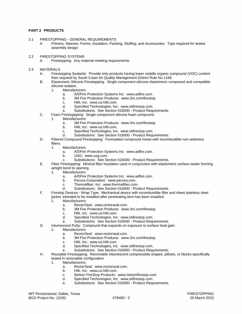
IMT Prestonwood, Dallas, Texas FIRESTOPPING BGO Project No. 13182 078400 - 2 26 March 2015
PART 2 PRODUCTS
2.1 FIRESTOPPING - GENERAL REQUIREMENTS A. Primers, Sleeves, Forms, Insulation, Packing, Stuffing, and Accessories: Type required for tested
assembly design.
2.2 FIRESTOPPING SYSTEMS A. Firestopping: Any material meeting requirements.
2.3 MATERIALS A. Firestopping Sealants: Provide only products having lower volatile organic compound (VOC) content
than required by South Coast Air Quality Management District Rule No.1168. B. Elastomeric Silicone Firestopping: Single component silicone elastomeric compound and compatible
silicone sealant. 1. Manufacturers:
a. A/DFire Protection Systems Inc: www.adfire.com. b. 3M Fire Protection Products: www.3m.com/firestop. c. Hilti, Inc: www.us.hilti.com. d. Specified Technologies, Inc: www.stifirestop.com. e. Substitutions: See Section 016000 - Product Requirements.
C. Foam Firestoppping: Single component silicone foam compound. 1. Manufacturers:
a. 3M Fire Protection Products: www.3m.com/firestop. b. Hilti, Inc: www.us.hilti.com. c. Specified Technologies, Inc: www.stifirestop.com. d. Substitutions: See Section 016000 - Product Requirements.
D. Fibered Compound Firestopping: Formulated compound mixed with incombustible non-asbestos fibers. 1. Manufacturers:
a. A/DFire Protection Systems Inc: www.adfire.com. b. USG: www.usg.com. c. Substitutions: See Section 016000 - Product Requirements.
E. Fiber Firestopping: Mineral fiber insulation used in conjunction with elastomeric surface sealer forming airtight bond to opening. 1. Manufacturers:
a. A/DFire Protection Systems Inc: www.adfire.com. b. Pecora Corporation: www.pecora.com. c. Thermafiber, Inc: www.thermafiber.com. d. Substitutions: See Section 016000 - Product Requirements.
F. Firestop Devices - Wrap Type: Mechanical device with incombustible filler and sheet stainless steel jacket, intended to be installed after penetrating item has been installed. 1. Manufacturers:
a. RectorSeal: www.rectorseal.com. b. 3M Fire Protection Products: www.3m.com/firestop. c. Hilti, Inc: www.us.hilti.com. d. Specified Technologies, Inc: www.stifirestop.com. e. Substitutions: See Section 016000 - Product Requirements.
G. Intumescent Putty: Compound that expands on exposure to surface heat gain. 1. Manufacturers:
a. RectorSeal: www.rectorseal.com. b. 3M Fire Protection Products: www.3m.com/firestop. c. Hilti, Inc: www.us.hilti.com. d. Specified Technologies, Inc: www.stifirestop.com. e. Substitutions: See Section 016000 - Product Requirements.
H. Reusable Firestopping: Removable intumescent compressible shapes, pillows, or blocks specifically tested in removable configuration. 1. Manufacturers:
a. RectorSeal: www.rectorseal.com. b. Hilti, Inc: www.us.hilti.com. c. Nelson FireStop Products: www.nelsonfirestop.com. d. Specified Technologies, Inc: www.stifirestop.com. e. Substitutions: See Section 016000 - Product Requirements.
IMT Prestonwood, Dallas, Texas FIRESTOPPING BGO Project No. 13182 078400 - 3 26 March 2015
I. Primers, Sleeves, Forms, Insulation, Packing, Stuffing, and Accessories: Type required for tested assembly design.
PART 3 EXECUTION
3.1 EXAMINATION A. Verify openings are ready to receive the work of this section.
3.2 PREPARATION A. Clean substrate surfaces of dirt, dust, grease, oil, loose material, or other matter that could adversely
affect bond of firestopping material. B. Remove incompatible materials that could adversely affect bond. C. Install backing materials to arrest liquid material leakage.
3.3 INSTALLATION A. Install materials in manner described in fire test report and in accordance with manufacturer's
instructions, completely closing openings. B. Do not cover installed firestopping until inspected by authority having jurisdiction. C. Install labeling required by code.
3.4 CLEANING A. Clean adjacent surfaces of firestopping materials.
3.5 PROTECTION A. Protect adjacent surfaces from damage by material installation.
END OF SECTION
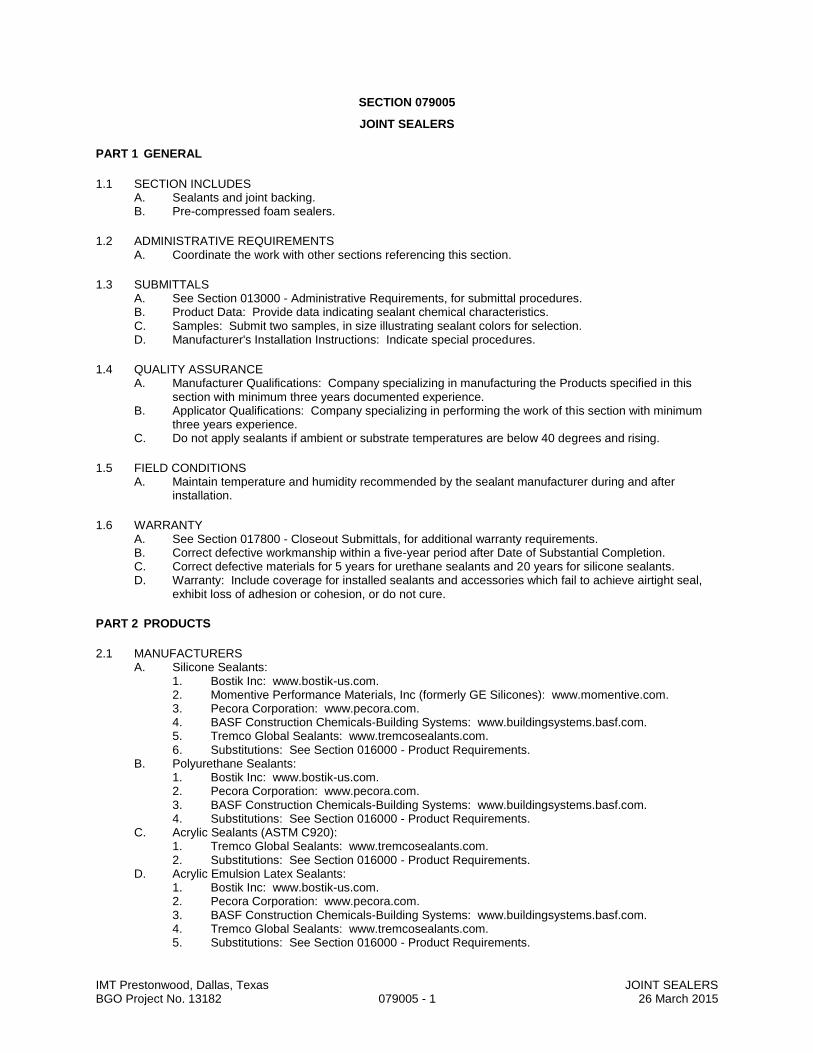
IMT Prestonwood, Dallas, Texas JOINT SEALERS BGO Project No. 13182 079005 - 1 26 March 2015
SECTION 079005
JOINT SEALERS
PART 1 GENERAL
1.1 SECTION INCLUDES A. Sealants and joint backing. B. Pre-compressed foam sealers.
1.2 ADMINISTRATIVE REQUIREMENTS A. Coordinate the work with other sections referencing this section.
1.3 SUBMITTALS A. See Section 013000 - Administrative Requirements, for submittal procedures. B. Product Data: Provide data indicating sealant chemical characteristics. C. Samples: Submit two samples, in size illustrating sealant colors for selection. D. Manufacturer's Installation Instructions: Indicate special procedures.
1.4 QUALITY ASSURANCE A. Manufacturer Qualifications: Company specializing in manufacturing the Products specified in this
section with minimum three years documented experience. B. Applicator Qualifications: Company specializing in performing the work of this section with minimum
three years experience. C. Do not apply sealants if ambient or substrate temperatures are below 40 degrees and rising.
1.5 FIELD CONDITIONS A. Maintain temperature and humidity recommended by the sealant manufacturer during and after
installation.
1.6 WARRANTY A. See Section 017800 - Closeout Submittals, for additional warranty requirements. B. Correct defective workmanship within a five-year period after Date of Substantial Completion. C. Correct defective materials for 5 years for urethane sealants and 20 years for silicone sealants. D. Warranty: Include coverage for installed sealants and accessories which fail to achieve airtight seal,
exhibit loss of adhesion or cohesion, or do not cure.
PART 2 PRODUCTS
2.1 MANUFACTURERS A. Silicone Sealants:
1. Bostik Inc: www.bostik-us.com. 2. Momentive Performance Materials, Inc (formerly GE Silicones): www.momentive.com. 3. Pecora Corporation: www.pecora.com. 4. BASF Construction Chemicals-Building Systems: www.buildingsystems.basf.com. 5. Tremco Global Sealants: www.tremcosealants.com. 6. Substitutions: See Section 016000 - Product Requirements.
B. Polyurethane Sealants: 1. Bostik Inc: www.bostik-us.com. 2. Pecora Corporation: www.pecora.com. 3. BASF Construction Chemicals-Building Systems: www.buildingsystems.basf.com. 4. Substitutions: See Section 016000 - Product Requirements.
C. Acrylic Sealants (ASTM C920): 1. Tremco Global Sealants: www.tremcosealants.com. 2. Substitutions: See Section 016000 - Product Requirements.
D. Acrylic Emulsion Latex Sealants: 1. Bostik Inc: www.bostik-us.com. 2. Pecora Corporation: www.pecora.com. 3. BASF Construction Chemicals-Building Systems: www.buildingsystems.basf.com. 4. Tremco Global Sealants: www.tremcosealants.com. 5. Substitutions: See Section 016000 - Product Requirements.

IMT Prestonwood, Dallas, Texas JOINT SEALERS BGO Project No. 13182 079005 - 2 26 March 2015
E. Preformed Compressible Foam Sealers: 1. EMSEAL Joint Systems, Ltd: www.emseal.com. 2. Sandell Manufacturing Company, Inc: www.sandellmfg.com. 3. Dayton Superior Corporation: www.daytonsuperior.com. 4. Tremco Global Sealants: www.tremcosealants.com. 5. Substitutions: See Section 016000 - Product Requirements.
2.2 SEALANTS A. Type AL-A - Acoustical Sealant: Butyl or acrylic sealant; ASTM C 920, Grade NS, Class 12-1/2, Uses
M and A; single component, solvent release curing, non-skinning. 1. Product: BA-98 manufactured by Pecora.
B. Type AL - Acrylic Sealant: ASTM C 920, Grade NS, Class 12-1/2, Uses NT, M, A, O; single component, solvent curing, non-staining, non-bleeding, non-sagging. 1. Color: Standard colors matching finished surfaces. 2. Product: Sonolac manufactured by Sonneborn. 3. Movement Capability: Plus and minus 12-1/2 percent. 4. Service Temperature Range: -13 to 180 degrees F. 5. Shore A Hardness Range: 25 to 50. 6. Applications: Use for:
C. Type U-MC – Non-sag Polyurethane Sealant: ASTM C 920, Grade NS, Class 25, Uses NT, I, M, A, G, O; single component, chemical curing, non-staining, non bleeding, capable of continuous water immersion, non-sagging type. 1. Color: Standard colors matching finished surfaces. 2. Product: NP-2 manufactured by Sonneborn. 3. Movement Capability: Plus and minus 25 percent. 4. Service Temperature Range: -40 to 180 degrees F. 5. Shore A Hardness Range: 20 to 35.
D. Type U-SL - Self-Leveling Polyurethane Sealant: ASTM C 920, Grade P, Class 25, Uses T, I, M, A, O; single component, chemical curing, non staining, non bleeding, capable of continuous water immersion, self-leveling type. 1. Color: Color as selected. 2. Product: SL-2 manufactured by Sonneborn. 3. Movement Capability: Plus and minus 25 percent. 4. Service Temperature Range: -40 to 180 degrees F. 5. Shore A Hardness Range: 20 to 35.
E. Type S-GP - Silicone Sealant: ASTM C 920, Grade NS, Class 25, Uses NT, A, G, M, O; single component, solvent curing, non-sagging, non-staining, fungus resistant, non-bleeding. 1. Color: Standard colors matching finished surfaces. 2. Product: 795 manufactured by Dow Corning. 3. Movement Capability: Plus and minus 25 percent. 4. Service Temperature Range: -65 to 180 degrees F. 5. Shore A Hardness Range: 15 to 35.
F. Type S-S - Silicone Sealant: ASTM C 920, Grane NS, Class 25, Uses NG, A, G, M, O; single component, non-sagging, non-staining, sanitary. 1. Color: Standard colors matching finished surfaces. 2. Product: 786 manufactured by Dow Corning. 3. Service Temperature Range: -65 to 180 degrees F. 4. Shore A Hardness Range: 15 to 35.
G. Pre-Formed Elastomeric Foam Seal (PF): Protectowrap Triple Guard energy Sill Sealer.
2.3 ACCESSORIES A. Primer: Non-staining type, recommended by sealant manufacturer to suit application. B. Joint Backing: Round foam rod compatible with sealant; ASTM D 1667, closed cell PVC; oversized 30
to 50 percent larger than joint width . C. Bond Breaker: Pressure sensitive tape recommended by sealant manufacturer to suit application.

IMT Prestonwood, Dallas, Texas JOINT SEALERS BGO Project No. 13182 079005 - 3 26 March 2015
PART 3 EXECUTION
3.1 EXAMINATION A. Verify that substrate surfaces are ready to receive work. B. Verify that joint backing and release tapes are compatible with sealant.
3.2 PREPARATION A. Remove loose materials and foreign matter that could impair adhesion of sealant. B. Clean and prime joints in accordance with manufacturer's instructions. C. Perform preparation in accordance with manufacturer's instructions and ASTM C1193. D. Protect elements surrounding the work of this section from damage or disfigurement.
3.3 INSTALLATION A. Perform work in accordance with sealant manufacturer's requirements for preparation of surfaces and
material installation instructions. B. Perform installation in accordance with ASTM C1193. C. Perform acoustical sealant application work in accordance with ASTM C919. D. Measure joint dimensions and size joint backers to achieve width-to-depth ratio, neck dimension, and
surface bond area as recommended by manufacturer , except where specific dimensions are indicated. E. Install bond breaker where joint backing is not used. F. Install sealant free of air pockets, foreign embedded matter, ridges, and sags. G. Apply sealant within recommended application temperature ranges. Consult manufacturer when
sealant cannot be applied within these temperature ranges. H. Tool joints concave. I. Pre-compressed Foam Sealant: Do not stretch; avoid joints except at corners, ends, and intersections;
install with face 1/8 to 1/4 inch below adjoining surface.
3.4 CLEANING A. Clean adjacent soiled surfaces.
3.5 PROTECTION A. Protect sealants until cured.
3.6 SCHEDULE A. Exterior Joints for Which No Other Sealant Type is Indicated: Type S-GP. B. Control and Expansion Joints in Paving: Type U-SL. C. Interior Wall Expansion Joints: Type U-MC. D. Exterior Wall Expansion Joints: Type S-GP. E. Control, Expansion, and Soft Joints in Masonry, and Between Masonry and Adjacent Work: Type S-
GP. F. Lap Joints in Exterior Sheet Metal Work: Type S-GP. G. Joints Between Exterior Metal Frames and Adjacent Work: Type S-GP. H. Under Exterior Door Thresholds: Type S-GP. I. Interior Joints for Which No Other Sealant is Indicated: Type AL. J. Control and Expansion Joints in Interior Concrete Slabs and Floors: Type U-SL. K. Joints Between Plumbing Fixtures and Walls and Floors, and Between Countertops and Walls: Type
S-S. L. In STC-Rated Walls, Between Metal Stud Track/Runner and Adjacent Construction: Type AL-A. M. Beneath Exterior Wall Sill Plates: Type PF.
END OF SECTION
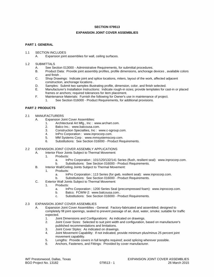
IMT Prestonwood, Dallas, Texas EXPANSION JOINT COVER ASSEMBLIES BGO Project No. 13182 079513 - 1 26 March 2015
SECTION 079513
EXPANSION JOINT COVER ASSEMBLIES
PART 1 GENERAL
1.1 SECTION INCLUDES A. Expansion joint assemblies for wall, ceiling surfaces.
1.2 SUBMITTALS A. See Section 013000 - Administrative Requirements, for submittal procedures. B. Product Data: Provide joint assembly profiles, profile dimensions, anchorage devices , available colors
and finish . C. Shop Drawings: Indicate joint and splice locations, miters, layout of the work, affected adjacent
construction, anchorage locations . D. Samples: Submit two samples illustrating profile, dimension, color, and finish selected. E. Manufacturer's Installation Instructions: Indicate rough-in sizes; provide templates for cast-in or placed
frames or anchors; required tolerances for item placement. F. Maintenance Materials: Furnish the following for Owner's use in maintenance of project.
1. See Section 016000 - Product Requirements, for additional provisions.
PART 2 PRODUCTS
2.1 MANUFACTURERS A. Expansion Joint Cover Assemblies:
1. Architectural Art Mfg., Inc : www.archart.com. 2. Balco Inc.: www.balcousa.com. 3. Construction Specialties, Inc : www.c-sgroup.com. 4. InPro Corporation : www.inprocorp.com. 5. MM Systems Corp : www.mmsystemscorp.com. 6. Substitutions: See Section 016000 - Product Requirements.
2.2 EXPANSION JOINT COVER ASSEMBLY APPLICATIONS A. Interior Floor Joints Subject to Thermal Movement:
1. Products: a. InPro Corporation ; 101/120/132/141 Series (flush, resilient seal): www.inprocorp.com. b. Substitutions: See Section 016000 - Product Requirements.
B. Interior Wall/Ceiling Joints Subject to Thermal Movement: 1. Products:
a. InPro Corporation ; 113 Series (for gwb, resilient seal): www.inprocorp.com. b. Substitutions: See Section 016000 - Product Requirements.
C. Exterior Wall Joints Subject to Thermal Movement: 1. Products:
a. InPro Corporation ; 1200 Series Seal (precompressed foam): www.inprocorp.com. b. Balco; FCWW-2: www.balcousa.com.. c. Substitutions: See Section 016000 - Product Requirements.
2.3 EXPANSION JOINT COVER ASSEMBLIES A. Expansion Joint Cover Assemblies - General: Factory-fabricated and assembled; designed to
completely fill joint openings, sealed to prevent passage of air, dust, water, smoke; suitable for traffic expected. 1. Joint Dimensions and Configurations: As indicated on drawings. 2. Joint Cover Sizes: Selected to suit joint width and configuration, based on manufacturer's
published recommendations and limitations. 3. Joint Cover Styles: As indicated on drawings. 4. Joint Movement Capability: If not indicated, provide minimum plus/minus 25 percent joint
movement capability. 5. Lengths: Provide covers in full lengths required; avoid splicing wherever possible. 6. Anchors, Fasteners, and Fittings: Provided by cover manufacturer.
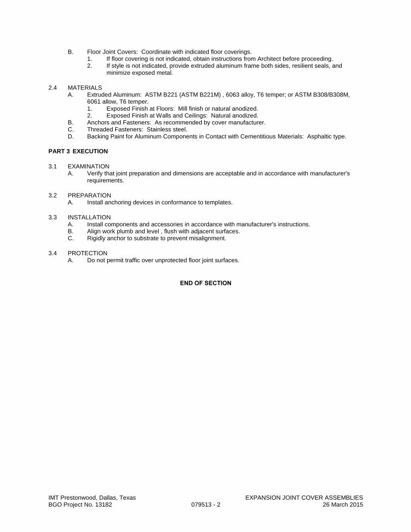
IMT Prestonwood, Dallas, Texas EXPANSION JOINT COVER ASSEMBLIES BGO Project No. 13182 079513 - 2 26 March 2015
B. Floor Joint Covers: Coordinate with indicated floor coverings. 1. If floor covering is not indicated, obtain instructions from Architect before proceeding. 2. If style is not indicated, provide extruded aluminum frame both sides, resilient seals, and
minimize exposed metal.
2.4 MATERIALS A. Extruded Aluminum: ASTM B221 (ASTM B221M) , 6063 alloy, T6 temper; or ASTM B308/B308M,
6061 allow, T6 temper. 1. Exposed Finish at Floors: Mill finish or natural anodized. 2. Exposed Finish at Walls and Ceilings: Natural anodized.
B. Anchors and Fasteners: As recommended by cover manufacturer. C. Threaded Fasteners: Stainless steel. D. Backing Paint for Aluminum Components in Contact with Cementitious Materials: Asphaltic type.
PART 3 EXECUTION
3.1 EXAMINATION A. Verify that joint preparation and dimensions are acceptable and in accordance with manufacturer's
requirements.
3.2 PREPARATION A. Install anchoring devices in conformance to templates.
3.3 INSTALLATION A. Install components and accessories in accordance with manufacturer's instructions. B. Align work plumb and level , flush with adjacent surfaces. C. Rigidly anchor to substrate to prevent misalignment.
3.4 PROTECTION A. Do not permit traffic over unprotected floor joint surfaces.
END OF SECTION

IMT Prestonwood, Dallas, Texas HOLLOW METAL DOORS AND FRAMES BGO Project No. 13182 081113 - 1 26 March 2015
SECTION 081113
HOLLOW METAL DOORS AND FRAMES
PART 1 GENERAL
1.1 SECTION INCLUDES A. Non-fire-rated steel doors and frames. B. Steel frames for wood doors. C. Fire-rated steel doors and frames. D. Thermally-insulated steel doors.
1.2 SUBMITTALS A. See Section 013000 - Administrative Requirements for submittal procedures. B. Product Data: Materials and details of design and construction, hardware locations, reinforcement type
and locations, anchorage and fastening methods, and finishes; and one copy of referenced grade standard.
C. Shop Drawings: Details of each opening, showing elevations, glazing, frame profiles, and identifying location of different finishes, if any.
D. Installation Instructions: Manufacturer's published instructions, including any special installation instructions relating to this project.
E. Manufacturer's Certificate: Certification that products meet or exceed specified requirements.
1.3 QUALITY ASSURANCE A. Manufacturer Qualifications: Company specializing in manufacturing the products specified in this
section with minimum three years documented experience. B. Maintain at the project site a copy of all reference standards dealing with installation.
1.4 DELIVERY, STORAGE, AND HANDLING A. Store in accordance with NAAMM HMMA 840. B. Protect with resilient packaging; avoid humidity build-up under coverings; prevent corrosion.
PART 2 PRODUCTS
2.1 MANUFACTURERS A. Steel Doors and Frames:
1. Assa Abloy Ceco, Curries, or Fleming: www.assaabloydss.com. 2. Republic Doors: www.republicdoor.com. 3. Steelcraft: www.steelcraft.com. 4. Substitutions: See Section 016000 - Product Requirements.
2.2 DOORS AND FRAMES A. Requirements for All Doors and Frames:
1. Accessibility: Comply with ANSI/ICC A117.1. 2. Door Top Closures: Flush with top of faces and edges. 3. Door Edge Profile: Beveled on both edges. 4. Door Texture: Smooth faces. 5. Glazed Lights: Non-removable stops on non-secure side; sizes and configurations as indicated
on drawings. 6. Hardware Preparation: In accordance with BHMA A156.115, with reinforcement welded in
place, in addition to other requirements specified in door grade standard. 7. Galvanizing for Units in Wet Areas: All components hot-dipped zinc-iron alloy-coated
(galvannealed), manufacturer's standard coating thickness. 8. Finish: Factory primed, for field finishing.
B. Combined Requirements: If a particular door and frame unit is indicated to comply with more than one type of requirement, comply with all the specified requirements for each type; for instance, an exterior door that is also indicated as being sound-rated must comply with the requirements specified for exterior doors and for sound-rated doors; where two requirements conflict, comply with the most stringent.
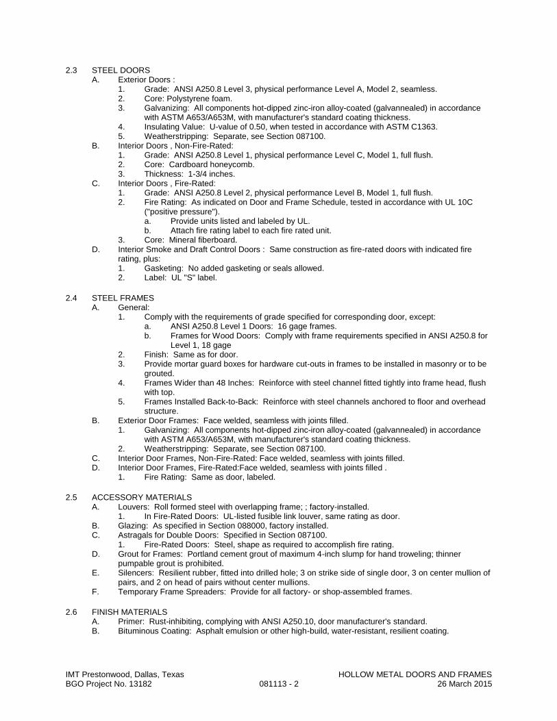
IMT Prestonwood, Dallas, Texas HOLLOW METAL DOORS AND FRAMES BGO Project No. 13182 081113 - 2 26 March 2015
2.3 STEEL DOORS A. Exterior Doors :
1. Grade: ANSI A250.8 Level 3, physical performance Level A, Model 2, seamless. 2. Core: Polystyrene foam. 3. Galvanizing: All components hot-dipped zinc-iron alloy-coated (galvannealed) in accordance
with ASTM A653/A653M, with manufacturer's standard coating thickness. 4. Insulating Value: U-value of 0.50, when tested in accordance with ASTM C1363. 5. Weatherstripping: Separate, see Section 087100.
B. Interior Doors , Non-Fire-Rated: 1. Grade: ANSI A250.8 Level 1, physical performance Level C, Model 1, full flush. 2. Core: Cardboard honeycomb. 3. Thickness: 1-3/4 inches.
C. Interior Doors , Fire-Rated: 1. Grade: ANSI A250.8 Level 2, physical performance Level B, Model 1, full flush. 2. Fire Rating: As indicated on Door and Frame Schedule, tested in accordance with UL 10C
("positive pressure"). a. Provide units listed and labeled by UL. b. Attach fire rating label to each fire rated unit.
3. Core: Mineral fiberboard. D. Interior Smoke and Draft Control Doors : Same construction as fire-rated doors with indicated fire
rating, plus: 1. Gasketing: No added gasketing or seals allowed. 2. Label: UL "S" label.
2.4 STEEL FRAMES A. General:
1. Comply with the requirements of grade specified for corresponding door, except: a. ANSI A250.8 Level 1 Doors: 16 gage frames. b. Frames for Wood Doors: Comply with frame requirements specified in ANSI A250.8 for
Level 1, 18 gage 2. Finish: Same as for door. 3. Provide mortar guard boxes for hardware cut-outs in frames to be installed in masonry or to be
grouted. 4. Frames Wider than 48 Inches: Reinforce with steel channel fitted tightly into frame head, flush
with top. 5. Frames Installed Back-to-Back: Reinforce with steel channels anchored to floor and overhead
structure. B. Exterior Door Frames: Face welded, seamless with joints filled.
1. Galvanizing: All components hot-dipped zinc-iron alloy-coated (galvannealed) in accordance with ASTM A653/A653M, with manufacturer's standard coating thickness.
2. Weatherstripping: Separate, see Section 087100. C. Interior Door Frames, Non-Fire-Rated: Face welded, seamless with joints filled. D. Interior Door Frames, Fire-Rated:Face welded, seamless with joints filled .
1. Fire Rating: Same as door, labeled.
2.5 ACCESSORY MATERIALS A. Louvers: Roll formed steel with overlapping frame; ; factory-installed.
1. In Fire-Rated Doors: UL-listed fusible link louver, same rating as door. B. Glazing: As specified in Section 088000, factory installed. C. Astragals for Double Doors: Specified in Section 087100.
1. Fire-Rated Doors: Steel, shape as required to accomplish fire rating. D. Grout for Frames: Portland cement grout of maximum 4-inch slump for hand troweling; thinner
pumpable grout is prohibited. E. Silencers: Resilient rubber, fitted into drilled hole; 3 on strike side of single door, 3 on center mullion of
pairs, and 2 on head of pairs without center mullions. F. Temporary Frame Spreaders: Provide for all factory- or shop-assembled frames.
2.6 FINISH MATERIALS A. Primer: Rust-inhibiting, complying with ANSI A250.10, door manufacturer's standard. B. Bituminous Coating: Asphalt emulsion or other high-build, water-resistant, resilient coating.

IMT Prestonwood, Dallas, Texas HOLLOW METAL DOORS AND FRAMES BGO Project No. 13182 081113 - 3 26 March 2015
PART 3 EXECUTION
3.1 EXAMINATION A. Verify existing conditions before starting work. B. Verify that opening sizes and tolerances are acceptable.
3.2 PREPARATION A. Coat inside of frames to be installed in masonry or to be grouted, with bituminous coating, prior to
installation.
3.3 INSTALLATION A. Install in accordance with the requirements of the specified door grade standard and NAAMM HMMA
840. B. In addition, install fire rated units in accordance with NFPA 80. C. Coordinate frame anchor placement with wall construction. D. Grout frames in masonry construction, using hand trowel methods; brace frames so that pressure of
grout before setting will not deform frames. E. Coordinate installation of hardware. F. Coordinate installation of glazing. G. Coordinate installation of electrical connections to electrical hardware items.
3.4 TOLERANCES A. Clearances Between Door and Frame: As specified in ANSI A250.8. B. Maximum Diagonal Distortion: 1/16 in measured with straight edge, corner to corner.
3.5 ADJUSTING A. Adjust for smooth and balanced door movement.
END OF SECTION
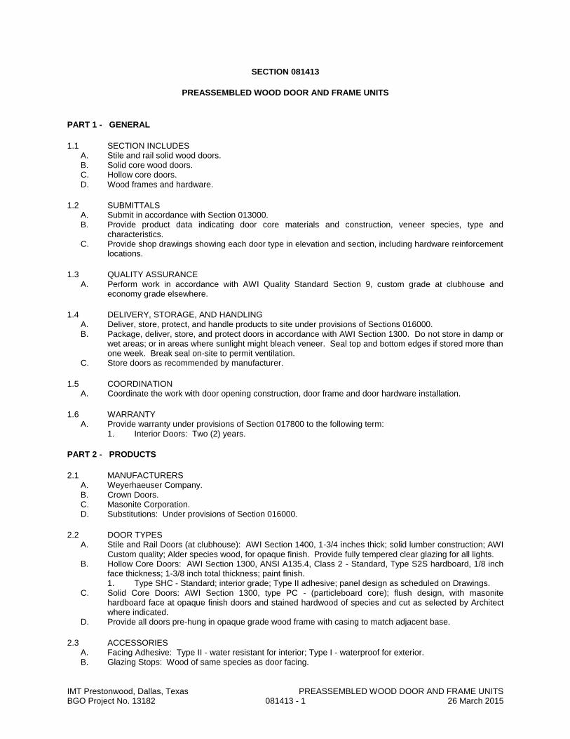
IMT Prestonwood, Dallas, Texas PREASSEMBLED WOOD DOOR AND FRAME UNITS BGO Project No. 13182 081413 - 1 26 March 2015
SECTION 081413
PREASSEMBLED WOOD DOOR AND FRAME UNITS
PART 1 - GENERAL
1.1 SECTION INCLUDES A. Stile and rail solid wood doors. B. Solid core wood doors. C. Hollow core doors. D. Wood frames and hardware.
1.2 SUBMITTALS A. Submit in accordance with Section 013000. B. Provide product data indicating door core materials and construction, veneer species, type and
characteristics. C. Provide shop drawings showing each door type in elevation and section, including hardware reinforcement
locations.
1.3 QUALITY ASSURANCE A. Perform work in accordance with AWI Quality Standard Section 9, custom grade at clubhouse and
economy grade elsewhere.
1.4 DELIVERY, STORAGE, AND HANDLING A. Deliver, store, protect, and handle products to site under provisions of Sections 016000. B. Package, deliver, store, and protect doors in accordance with AWI Section 1300. Do not store in damp or
wet areas; or in areas where sunlight might bleach veneer. Seal top and bottom edges if stored more than one week. Break seal on-site to permit ventilation.
C. Store doors as recommended by manufacturer.
1.5 COORDINATION A. Coordinate the work with door opening construction, door frame and door hardware installation.
1.6 WARRANTY A. Provide warranty under provisions of Section 017800 to the following term:
1. Interior Doors: Two (2) years.
PART 2 - PRODUCTS
2.1 MANUFACTURERS A. Weyerhaeuser Company. B. Crown Doors. C. Masonite Corporation. D. Substitutions: Under provisions of Section 016000.
2.2 DOOR TYPES A. Stile and Rail Doors (at clubhouse): AWI Section 1400, 1-3/4 inches thick; solid lumber construction; AWI
Custom quality; Alder species wood, for opaque finish. Provide fully tempered clear glazing for all lights. B. Hollow Core Doors: AWI Section 1300, ANSI A135.4, Class 2 - Standard, Type S2S hardboard, 1/8 inch
face thickness; 1-3/8 inch total thickness; paint finish. 1. Type SHC - Standard; interior grade; Type II adhesive; panel design as scheduled on Drawings.
C. Solid Core Doors: AWI Section 1300, type PC - (particleboard core); flush design, with masonite hardboard face at opaque finish doors and stained hardwood of species and cut as selected by Architect where indicated.
D. Provide all doors pre-hung in opaque grade wood frame with casing to match adjacent base.
2.3 ACCESSORIES A. Facing Adhesive: Type II - water resistant for interior; Type I - waterproof for exterior. B. Glazing Stops: Wood of same species as door facing.
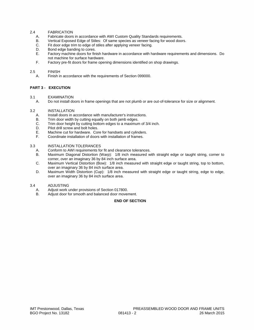
IMT Prestonwood, Dallas, Texas PREASSEMBLED WOOD DOOR AND FRAME UNITS BGO Project No. 13182 081413 - 2 26 March 2015
2.4 FABRICATION A. Fabricate doors in accordance with AWI Custom Quality Standards requirements. B. Vertical Exposed Edge of Stiles: Of same species as veneer facing for wood doors. C. Fit door edge trim to edge of stiles after applying veneer facing. D. Bond edge banding to cores. E. Factory machine doors for finish hardware in accordance with hardware requirements and dimensions. Do
not machine for surface hardware. F. Factory pre-fit doors for frame opening dimensions identified on shop drawings.
2.5 FINISH A. Finish in accordance with the requirements of Section 099000.
PART 3 - EXECUTION
3.1 EXAMINATION A. Do not install doors in frame openings that are not plumb or are out-of-tolerance for size or alignment.
3.2 INSTALLATION A. Install doors in accordance with manufacturer's instructions. B. Trim door width by cutting equally on both jamb edges. C. Trim door height by cutting bottom edges to a maximum of 3/4 inch. D. Pilot drill screw and bolt holes. E. Machine cut for hardware. Core for handsets and cylinders. F. Coordinate installation of doors with installation of frames.
3.3 INSTALLATION TOLERANCES A. Conform to AWI requirements for fit and clearance tolerances. B. Maximum Diagonal Distortion (Warp): 1/8 inch measured with straight edge or taught string, corner to
corner, over an imaginary 36 by 84 inch surface area. C. Maximum Vertical Distortion (Bow): 1/8 inch measured with straight edge or taught string, top to bottom,
over an imaginary 36 by 84 inch surface area. D. Maximum Width Distortion (Cup): 1/8 inch measured with straight edge or taught string, edge to edge,
over an imaginary 36 by 84 inch surface area.
3.4 ADJUSTING A. Adjust work under provisions of Section 017800. B. Adjust door for smooth and balanced door movement.
END OF SECTION
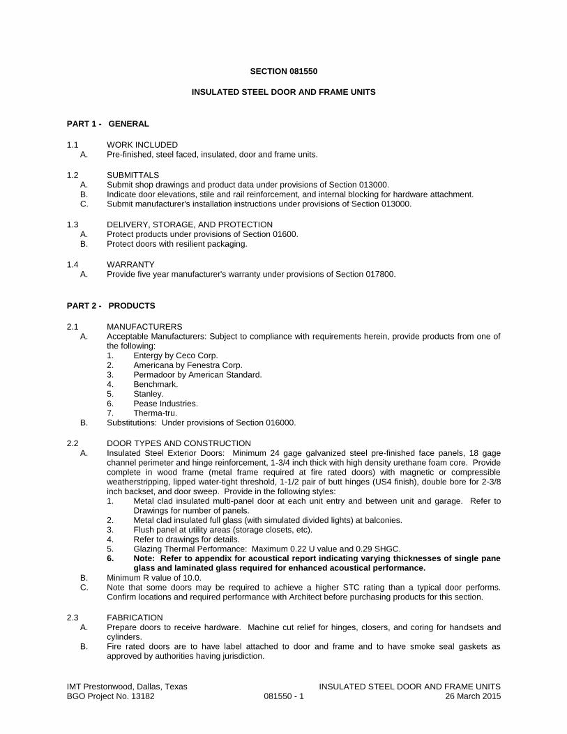
IMT Prestonwood, Dallas, Texas INSULATED STEEL DOOR AND FRAME UNITS BGO Project No. 13182 081550 - 1 26 March 2015
SECTION 081550
INSULATED STEEL DOOR AND FRAME UNITS
PART 1 - GENERAL
1.1 WORK INCLUDED A. Pre-finished, steel faced, insulated, door and frame units.
1.2 SUBMITTALS A. Submit shop drawings and product data under provisions of Section 013000. B. Indicate door elevations, stile and rail reinforcement, and internal blocking for hardware attachment. C. Submit manufacturer's installation instructions under provisions of Section 013000.
1.3 DELIVERY, STORAGE, AND PROTECTION A. Protect products under provisions of Section 01600. B. Protect doors with resilient packaging.
1.4 WARRANTY A. Provide five year manufacturer's warranty under provisions of Section 017800.
PART 2 - PRODUCTS
2.1 MANUFACTURERS A. Acceptable Manufacturers: Subject to compliance with requirements herein, provide products from one of
the following: 1. Entergy by Ceco Corp. 2. Americana by Fenestra Corp. 3. Permadoor by American Standard. 4. Benchmark. 5. Stanley. 6. Pease Industries. 7. Therma-tru.
B. Substitutions: Under provisions of Section 016000.
2.2 DOOR TYPES AND CONSTRUCTION A. Insulated Steel Exterior Doors: Minimum 24 gage galvanized steel pre-finished face panels, 18 gage
channel perimeter and hinge reinforcement, 1-3/4 inch thick with high density urethane foam core. Provide complete in wood frame (metal frame required at fire rated doors) with magnetic or compressible weatherstripping, lipped water-tight threshold, 1-1/2 pair of butt hinges (US4 finish), double bore for 2-3/8 inch backset, and door sweep. Provide in the following styles: 1. Metal clad insulated multi-panel door at each unit entry and between unit and garage. Refer to
Drawings for number of panels. 2. Metal clad insulated full glass (with simulated divided lights) at balconies. 3. Flush panel at utility areas (storage closets, etc). 4. Refer to drawings for details. 5. Glazing Thermal Performance: Maximum 0.22 U value and 0.29 SHGC. 6. Note: Refer to appendix for acoustical report indicating varying thicknesses of single pane
glass and laminated glass required for enhanced acoustical performance.
B. Minimum R value of 10.0. C. Note that some doors may be required to achieve a higher STC rating than a typical door performs.
Confirm locations and required performance with Architect before purchasing products for this section.
2.3 FABRICATION A. Prepare doors to receive hardware. Machine cut relief for hinges, closers, and coring for handsets and
cylinders. B. Fire rated doors are to have label attached to door and frame and to have smoke seal gaskets as
approved by authorities having jurisdiction.

IMT Prestonwood, Dallas, Texas INSULATED STEEL DOOR AND FRAME UNITS BGO Project No. 13182 081550 - 2 26 March 2015
2.4 FINISH A. Prime paint facing and edges. B. Finish: Prime painted for field finishing.
PART 3 - EXECUTION
3.1 INSTALLATION A. Install doors and frames in accordance with manufacturer's instructions. B. Pilot drill screw and bolt holes. C. Prepare doors to receive finish hardware. D. Install hardware in accordance with manufacturer's instructions. E. Conform to manufacturer's recommendations for fit tolerances. F. Set door threshold in bed of mastic.
3.2 INSTALLATION TOLERANCES A. Maximum Diagonal Distortion: 1/16 inch measured with straight edge, corner to corner.
3.3 ADJUSTING/CLEANING/REPAIR/REPLACEMENT A. Adjust for smooth and balanced door movement. B. Do not install doors with dents or scratches. C. Clean doors prior to field painting.
END OF SECTION

IMT Prestonwood, Dallas, Texas ACCESS DOORS AND PANELS BGO Project No. 13182 083100 - 1 26 March 2015
SECTION 083100
ACCESS DOORS AND PANELS
PART 1 GENERAL
1.1 SECTION INCLUDES A. Wall access door and frame units. B. Ceiling access door and frame units.
1.2 SUBMITTALS A. See Section 013000 - Administrative Requirements, for submittal procedures. B. Product Data: Provide sizes, types, finishes, hardware, scheduled locations, and details of adjoining
work. C. Manufacturer's Installation Instructions: Indicate installation requirements. D. Project Record Documents: Record actual locations of all access units.
PART 2 PRODUCTS
2.1 ACCESS DOOR AND PANEL APPLICATIONS
2.2 WALL AND CEILING UNITS A. Manufacturers:
1. Acudor Products Inc : www.acudor.com. 2. Karp Associates, Inc : www.karpinc.com. 3. Milcor by Commercial Products Group of Hart & Cooley, Inc : www.milcorinc.com. 4. Substitutions: See Section 016000 - Product Requirements.
B. Access Doors: Factory fabricated door and frame units, fully assembled units with corner joints welded, filled, and ground flush; square and without rack or warp; coordinate requirements with assemblies units are to be installed in. 1. Material: Steel. 2. Door Style: Single thickness with rolled or turned in edges. 3. Frames and flanges: 0.058 inch steel. 4. Door panels: 0.070 inch single thickness steel sheet. 5. Units in Fire Rated Assemblies: Fire rating as required by applicable code for the fire rated
assembly in which they are to be installed. a. Provide products listed and labeled by UL or ITS (Warnock Hersey) as suitable for the
purpose specified and indicated. b. Provide certificate of compliance from authority having jurisdiction indicating approval of
fire rated doors. 6. Steel Finish: Primed. 7. Primed Finish: Polyester powder coat; manufacturer's standard color. 8. Size(s): As indicated. 9. Hardware:
a. Hardware for Fire Rated Units: As required for listing. b. Hinges for Non-Fire-Rated Units: Concealed, constant force closure spring type. c. Hinge: Non-Fire-Rated Units: 175 degree steel hinges with removable pin. d. Latch/Lock: Screw driver slot for quarter turn cam latch.
10. Galvanized, hot dipped finish. 11. Stainless steel at wet locations.
PART 3 EXECUTION
3.1 EXAMINATION A. Verify that rough openings are correctly sized and located.
3.2 INSTALLATION A. Install units in accordance with manufacturer's instructions. B. Install frames plumb and level in openings. Secure rigidly in place. C. Position units to provide convenient access to the concealed work requiring access.
END OF SECTION

IMT Prestonwood, Dallas, Texas OVERHEAD COILING DOORS BGO Project No. 13182 083323 - 1 26 March 2015
SECTION 083323
OVERHEAD COILING DOORS
PART 1 GENERAL
1.1 SECTION INCLUDES A. Overhead coiling doors , operating hardware, fire-rated, non-fire-rated, and exterior, electric operation. B. Wiring from electric circuit disconnect to operator to control station.
1.2 SUBMITTALS A. See Section 013000 - Administrative Requirements, for submittal procedures. B. Product Data: Provide general construction, component connections and details, electrical equipment. C. Shop Drawings: Indicate pertinent dimensioning, anchorage methods, hardware locations, and
installation details. D. Manufacturer's Instructions: Indicate installation sequence and procedures, adjustment and alignment
procedures. E. Maintenance Data: Indicate lubrication requirements and frequency and periodic adjustments
required.
1.3 QUALITY ASSURANCE A. Products Requiring Electrical Connection: Listed and classified by testing firm acceptable to the
authority having jurisdiction as suitable for the purpose specified and indicated.
PART 2 PRODUCTS
2.1 MANUFACTURERS A. Overhead Coiling Doors:
1. Alpine Overhead Doors, Inc: www.alpinedoors.com. 2. Cornell Iron Works, Inc: www.cornelliron.com. 3. The Cookson Company: www.cooksondoor.com. 4. Wayne-Dalton, a Division of Overhead Door Corporation: www.wayne-dalton.com. 5. Substitutions: See Section 016000 - Product Requirements.
2.2 COILING DOORS A. Exterior Coiling Doors: Steel slat curtain.
1. Capable of withstanding positive and negative wind loads of 20 psf, without undue deflection or damage to components.
2. Sandwich slat construction with insulated core of manufacturer's standard type insulation; insulation (u-) value: 0.50 BTU/hr sq ft deg F
3. Nominal Slat Size: 2 inches wide x required length. a. Vision Panels: Approximately 10- by 1-5/8-inch openings spaced approximately 2
inches apart and beginning 12 inches from end guides; in number and configuration as indicated on Drawings; installed with insulated vision-panel glazing.
4. Finish: Galvanized. 5. Guides: Angles; galvanized steel. 6. Hood Enclosure: Manufacturer's standard; galvanized steel. 7. Electric operation. 8. Mounting: As indicated. 9. Exterior lock and latch handle.
B. Fire-Rated Coiling Doors: Steel slat curtain; conform to NFPA 80. 1. Provide products listed and labeled by UL or ITS (Warnock Hersey) as suitable for the purpose
specified and indicated. 2. Oversized Openings: Provide certificate of compliance from authority having jurisdiction
indicating approval of fire rated units and operating hardware assembly. 3. Single thickness slats. 4. Nominal Slat Size: 3 inches wide x required length. 5. Finish: Primed. 6. Guides: Angles; primed steel. 7. Hood Enclosure: Manufacturer's standard; primed steel. 8. Release Mechanism: Fire alarm system activated with automatically governed closing speed.

IMT Prestonwood, Dallas, Texas OVERHEAD COILING DOORS BGO Project No. 13182 083323 - 2 26 March 2015
9. Electric operation. 10. Mounting: Within framed opening.
2.3 MATERIALS A. Curtain Construction: Interlocking slats.
1. Slat Ends: Alternate slats fitted with end locks to act as wearing surface in guides and to prevent lateral movement.
2. Curtain Bottom: Fitted with angles to provide reinforcement and positive contact in closed position.
3. Weatherstripping: Moisture and rot proof, resilient type, located at jamb edges, bottom of curtain, and where curtain enters hood enclosure of exterior doors.
B. Steel Slats: ASTM A653/A653M galvanized steel sheet. 1. Galvanizing: Minimum G90/Z275 coating.
C. Guide Construction: Continuous, of profile to retain door in place with snap-on trim, mounting brackets of same metal.
D. Steel Guides: ASTM A36/A36M steel angles, size as indicated, hot-dip galvanized per ASTM A 123/A 123M.
E. Hood Enclosure: Internally reinforced to maintain rigidity and shape. F. Roller Shaft Counterbalance: Steel pipe and helical steel spring system, capable of producing torque
sufficient to ensure smooth operation of curtain from any position and capable of holding position at mid-travel; with adjustable spring tension; requiring 25 lb nominal force to operate.
2.4 ELECTRIC OPERATION A. Electric Operators:
1. Mounting: As indicated. 2. Motor Rating: 1/2 hp; continuous duty. 3. Motor Controller: NEMA ICS 2, full voltage, reversing magnetic motor starter. 4. Controller Enclosure: NEMA 250 Type 1. 5. Opening Speed: 12 inches per second. 6. Brake: Adjustable friction clutch type, activated by motor controller. 7. Manual override in case of power failure.
B. Control Station: Standard three button (OPEN-STOP-CLOSE) momentary control for each operator. 1. 24 volt circuit.
C. Safety Edge: Located at bottom of curtain, full width, electro-mechanical sensitized type, wired to stop operator upon striking object, hollow neoprene covered.
PART 3 EXECUTION
3.1 EXAMINATION A. Verify that opening sizes, tolerances and conditions are acceptable.
3.2 INSTALLATION A. Install units in accordance with manufacturer's instructions. B. In addition, install fire-rated doors in accordance with NFPA 80. C. Use anchorage devices to securely fasten assembly to wall construction and building framing without
distortion or stress. D. Securely and rigidly brace components suspended from structure. Secure guides to structural
members only. E. Fit and align assembly including hardware; level and plumb, to provide smooth operation. F. Coordinate installation of electrical service with Section 262717. G. Complete wiring from disconnect to unit components. H. Complete wiring from fire alarm system. I. Coordinate installation of sealants and backing materials at frame perimeter as specified in Section
079005. J. Install perimeter trim and closures.
3.3 TOLERANCES A. Maintain dimensional tolerances and alignment with adjacent work. B. Maximum Variation From Plumb: 1/16 inch. C. Maximum Variation From Level: 1/16 inch. D. Longitudinal or Diagonal Warp: Plus or minus 1/8 inch per 10 ft straight edge.

IMT Prestonwood, Dallas, Texas OVERHEAD COILING DOORS BGO Project No. 13182 083323 - 3 26 March 2015
3.4 ADJUSTING A. Adjust operating assemblies for smooth and noiseless operation.
3.5 CLEANING A. Clean installed components. B. Remove labels and visible markings.
END OF SECTION
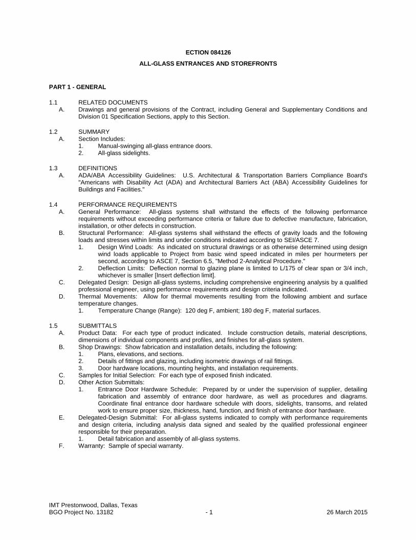
IMT Prestonwood, Dallas, Texas BGO Project No. 13182 - 1 26 March 2015
ECTION 084126
ALL-GLASS ENTRANCES AND STOREFRONTS
PART 1 - GENERAL
1.1 RELATED DOCUMENTS A. Drawings and general provisions of the Contract, including General and Supplementary Conditions and
Division 01 Specification Sections, apply to this Section.
1.2 SUMMARY A. Section Includes:
1. Manual-swinging all-glass entrance doors. 2. All-glass sidelights.
1.3 DEFINITIONS A. ADA/ABA Accessibility Guidelines: U.S. Architectural & Transportation Barriers Compliance Board's
"Americans with Disability Act (ADA) and Architectural Barriers Act (ABA) Accessibility Guidelines for Buildings and Facilities."
1.4 PERFORMANCE REQUIREMENTS A. General Performance: All-glass systems shall withstand the effects of the following performance
requirements without exceeding performance criteria or failure due to defective manufacture, fabrication, installation, or other defects in construction.
B. Structural Performance: All-glass systems shall withstand the effects of gravity loads and the following loads and stresses within limits and under conditions indicated according to SEI/ASCE 7. 1. Design Wind Loads: As indicated on structural drawings or as otherwise determined using design
wind loads applicable to Project from basic wind speed indicated in miles per hourmeters per second, according to ASCE 7, Section 6.5, "Method 2-Analytical Procedure."
2. Deflection Limits: Deflection normal to glazing plane is limited to L/175 of clear span or 3/4 inch, whichever is smaller [Insert deflection limit].
C. Delegated Design: Design all-glass systems, including comprehensive engineering analysis by a qualified professional engineer, using performance requirements and design criteria indicated.
D. Thermal Movements: Allow for thermal movements resulting from the following ambient and surface temperature changes. 1. Temperature Change (Range): 120 deg F, ambient; 180 deg F, material surfaces.
1.5 SUBMITTALS A. Product Data: For each type of product indicated. Include construction details, material descriptions,
dimensions of individual components and profiles, and finishes for all-glass system. B. Shop Drawings: Show fabrication and installation details, including the following:
1. Plans, elevations, and sections. 2. Details of fittings and glazing, including isometric drawings of rail fittings. 3. Door hardware locations, mounting heights, and installation requirements.
C. Samples for Initial Selection: For each type of exposed finish indicated. D. Other Action Submittals:
1. Entrance Door Hardware Schedule: Prepared by or under the supervision of supplier, detailing fabrication and assembly of entrance door hardware, as well as procedures and diagrams. Coordinate final entrance door hardware schedule with doors, sidelights, transoms, and related work to ensure proper size, thickness, hand, function, and finish of entrance door hardware.
E. Delegated-Design Submittal: For all-glass systems indicated to comply with performance requirements and design criteria, including analysis data signed and sealed by the qualified professional engineer responsible for their preparation. 1. Detail fabrication and assembly of all-glass systems.
F. Warranty: Sample of special warranty.
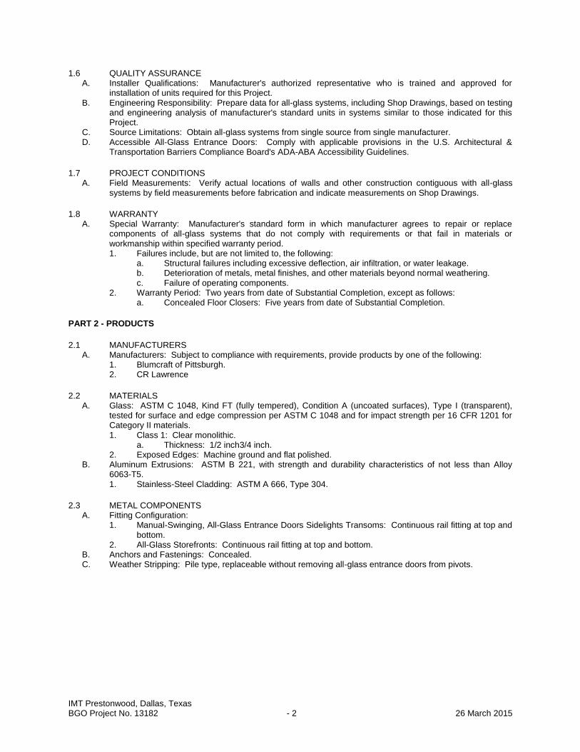
IMT Prestonwood, Dallas, Texas BGO Project No. 13182 - 2 26 March 2015
1.6 QUALITY ASSURANCE A. Installer Qualifications: Manufacturer's authorized representative who is trained and approved for
installation of units required for this Project. B. Engineering Responsibility: Prepare data for all-glass systems, including Shop Drawings, based on testing
and engineering analysis of manufacturer's standard units in systems similar to those indicated for this Project.
C. Source Limitations: Obtain all-glass systems from single source from single manufacturer. D. Accessible All-Glass Entrance Doors: Comply with applicable provisions in the U.S. Architectural &
Transportation Barriers Compliance Board's ADA-ABA Accessibility Guidelines.
1.7 PROJECT CONDITIONS A. Field Measurements: Verify actual locations of walls and other construction contiguous with all-glass
systems by field measurements before fabrication and indicate measurements on Shop Drawings.
1.8 WARRANTY A. Special Warranty: Manufacturer's standard form in which manufacturer agrees to repair or replace
components of all-glass systems that do not comply with requirements or that fail in materials or workmanship within specified warranty period. 1. Failures include, but are not limited to, the following:
a. Structural failures including excessive deflection, air infiltration, or water leakage. b. Deterioration of metals, metal finishes, and other materials beyond normal weathering. c. Failure of operating components.
2. Warranty Period: Two years from date of Substantial Completion, except as follows: a. Concealed Floor Closers: Five years from date of Substantial Completion.
PART 2 - PRODUCTS
2.1 MANUFACTURERS A. Manufacturers: Subject to compliance with requirements, provide products by one of the following:
1. Blumcraft of Pittsburgh. 2. CR Lawrence
2.2 MATERIALS A. Glass: ASTM C 1048, Kind FT (fully tempered), Condition A (uncoated surfaces), Type I (transparent),
tested for surface and edge compression per ASTM C 1048 and for impact strength per 16 CFR 1201 for Category II materials. 1. Class 1: Clear monolithic.
a. Thickness: 1/2 inch3/4 inch. 2. Exposed Edges: Machine ground and flat polished.
B. Aluminum Extrusions: ASTM B 221, with strength and durability characteristics of not less than Alloy 6063-T5. 1. Stainless-Steel Cladding: ASTM A 666, Type 304.
2.3 METAL COMPONENTS A. Fitting Configuration:
1. Manual-Swinging, All-Glass Entrance Doors Sidelights Transoms: Continuous rail fitting at top and bottom.
2. All-Glass Storefronts: Continuous rail fitting at top and bottom. B. Anchors and Fastenings: Concealed. C. Weather Stripping: Pile type, replaceable without removing all-glass entrance doors from pivots.

IMT Prestonwood, Dallas, Texas BGO Project No. 13182 - 3 26 March 2015
2.4 ENTRANCE DOOR HARDWARE A. General: Heavy-duty entrance door hardware units in sizes, quantities, and types recommended by
manufacturer for all-glass entrance systems indicated. For exposed parts, match metal and finish of rail fittings.
B. Concealed Floor Closers and Top Pivots: Center hung; BHMA A156.4, Grade 1; including cases, bottom arms, top walking beam pivots, plates, and accessories required for complete installation. 1. Swing: Single acting.
a. Positive Dead Stop: Coordinated with hold-open angle if any, or at angle selected. 2. Hold Open: Automatic, at angle selected. 3. Opening-Force Requirements:
a. Egress Doors: Not more than 15 lb/f to release the latch and not more than 30 lb/f to set the door in motion and not more than 15 lb/f to open the door to its minimum required width.
b. Accessible Interior Swinging Sliding Doors: Not more than 5 lb/f to fully open door. C. Push-Pull Set: As indicated on hardware schedule. D. Exit Devices: as indicated on hardware schedule E. Threshold: As indicated on hardware schedule, but not more than 1/2 inch high.
2.5 FABRICATION A. Provide holes and cutouts in glass to receive hardware, fittings, and accessory fittings before tempering
glass. Do not cut, drill, or make other alterations to glass after tempering. 1. Fully temper glass using horizontal (roller-hearth) process, and fabricate so that when glass is
installed, roll-wave distortion is parallel with bottom edge of door or lite. B. Factory assemble components and factory install hardware and fittings to greatest extent possible.
PART 3 - EXECUTION
3.1 EXAMINATION A. Examine areas and conditions, with Installer present, for compliance with requirements for installation
tolerances and other conditions affecting performance of the Work. B. Proceed with installation only after unsatisfactory conditions have been corrected.
3.2 INSTALLATION A. Install all-glass systems and associated components according to manufacturer's written instructions. B. Set units level, plumb, and true to line, with uniform joints. C. Maintain uniform clearances between adjacent components. D. Lubricate hardware and other moving parts according to manufacturer's written instructions. E. Set, seal, and grout floor closer cases as required to suit hardware and substrate indicated. F. Install joint sealants as specified in Division 07 Section "Joint Sealants" and to produce weathertight
installation.
3.3 ADJUSTING AND CLEANING A. Adjust all-glass entrance doors and hardware to produce smooth operation and tight fit at contact points
and weather stripping. 1. For all-glass entrance doors accessible to people with disabilities, adjust closers to provide a 3-
second closer sweep period for doors to move from a 70-degree open position to 3 inches from the latch measured to the leading door edge.
B. Remove excess sealant and glazing compounds and dirt from surfaces.
END OF SECTION

IMT Prestonwood, Dallas, Texas ALUMINUM-FRAMED STOREFRONTS BGO Project No. 13182 084313 - 1 26 March 2015
SECTION 084313
ALUMINUM-FRAMED STOREFRONTS
PART 1 GENERAL
1.1 SECTION INCLUDES A. Aluminum-framed storefront, with vision glass. B. Infill panels of glass. C. Aluminum doors and frames. D. Weatherstripping. E. Door hardware. F. Perimeter sealant.
1.2 ADMINISTRATIVE REQUIREMENTS A. Coordinate with installation of other components that comprise the exterior enclosure. B. Preinstallation Meeting: Conduct a preinstallation meeting one week before starting work of this
section; require attendance by all affected installers.
1.3 SUBMITTALS A. See Section 013000 - Administrative Requirements, for submittal procedures. B. Product Data: Provide component dimensions, describe components within assembly, anchorage and
fasteners, glass and infill, door hardware, internal drainage details. C. Shop Drawings: Provide Engineered, sealed shop drawings indicating system dimensions, framed
opening requirements and tolerances, affected related Work, expansion and contraction joint location and details, and field welding required.
D. Design Data: Provide framing member structural and physical characteristics, engineering calculations, dimensional limitations.
E. Hardware Schedule: Complete itemization of each item of hardware to be provided for each door, cross-referenced to door identification numbers in Contract Documents.
F. Warranty: Submit manufacturer warranty and ensure forms have been completed in Owner's name and registered with manufacturer.
1.4 QUALITY ASSURANCE A. Designer Qualifications: Design structural support framing components under direct supervision of a
Professional Structural Engineer experienced in design of this Work and licensed at the State in which the Project is located.
B. Manufacturer and Installer Qualifications: Company specializing in manufacturing aluminum glazing systems with minimum three years of documented experience.
1.5 DELIVERY, STORAGE, AND HANDLING A. Handle products of this section in accordance with AAMA CW-10. B. Protect finished aluminum surfaces with wrapping. Do not use adhesive papers or sprayed coatings
that bond to aluminum when exposed to sunlight or weather.
1.6 FIELD CONDITIONS A. Do not install sealants when ambient temperature is less than 40 degrees F. Maintain this minimum
temperature during and 48 hours after installation.
1.7 WARRANTY A. See Section 017800 - Closeout Submittals, for additional warranty requirements. B. Correct defective Work within a five year period after Date of Substantial Completion. C. Provide five year manufacturer warranty against excessive degradation of exterior finish. Include
provision for replacement of units with excessive fading, chalking, or flaking.
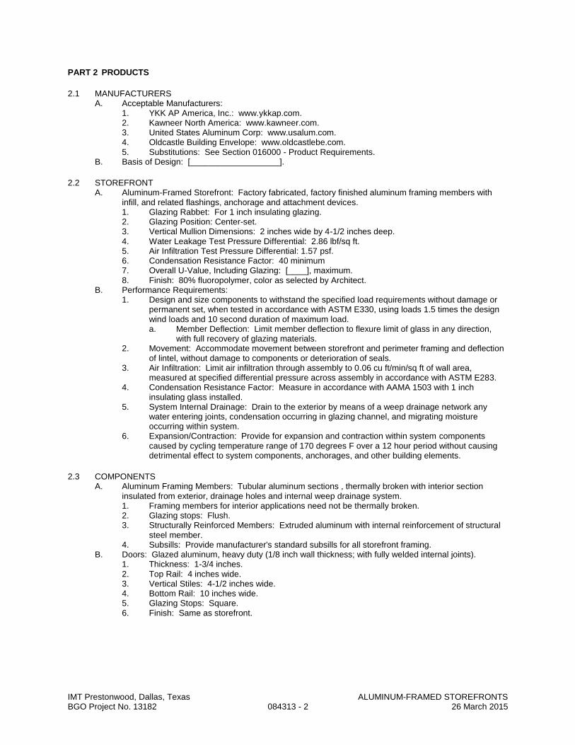
IMT Prestonwood, Dallas, Texas ALUMINUM-FRAMED STOREFRONTS BGO Project No. 13182 084313 - 2 26 March 2015
PART 2 PRODUCTS
2.1 MANUFACTURERS A. Acceptable Manufacturers:
1. YKK AP America, Inc.: www.ykkap.com. 2. Kawneer North America: www.kawneer.com. 3. United States Aluminum Corp: www.usalum.com. 4. Oldcastle Building Envelope: www.oldcastlebe.com. 5. Substitutions: See Section 016000 - Product Requirements.
B. Basis of Design: [___________________].
2.2 STOREFRONT A. Aluminum-Framed Storefront: Factory fabricated, factory finished aluminum framing members with
infill, and related flashings, anchorage and attachment devices. 1. Glazing Rabbet: For 1 inch insulating glazing. 2. Glazing Position: Center-set. 3. Vertical Mullion Dimensions: 2 inches wide by 4-1/2 inches deep. 4. Water Leakage Test Pressure Differential: 2.86 lbf/sq ft. 5. Air Infiltration Test Pressure Differential: 1.57 psf. 6. Condensation Resistance Factor: 40 minimum 7. Overall U-Value, Including Glazing: [____], maximum. 8. Finish: 80% fluoropolymer, color as selected by Architect.
B. Performance Requirements: 1. Design and size components to withstand the specified load requirements without damage or
permanent set, when tested in accordance with ASTM E330, using loads 1.5 times the design wind loads and 10 second duration of maximum load. a. Member Deflection: Limit member deflection to flexure limit of glass in any direction,
with full recovery of glazing materials. 2. Movement: Accommodate movement between storefront and perimeter framing and deflection
of lintel, without damage to components or deterioration of seals. 3. Air Infiltration: Limit air infiltration through assembly to 0.06 cu ft/min/sq ft of wall area,
measured at specified differential pressure across assembly in accordance with ASTM E283. 4. Condensation Resistance Factor: Measure in accordance with AAMA 1503 with 1 inch
insulating glass installed. 5. System Internal Drainage: Drain to the exterior by means of a weep drainage network any
water entering joints, condensation occurring in glazing channel, and migrating moisture occurring within system.
6. Expansion/Contraction: Provide for expansion and contraction within system components caused by cycling temperature range of 170 degrees F over a 12 hour period without causing detrimental effect to system components, anchorages, and other building elements.
2.3 COMPONENTS A. Aluminum Framing Members: Tubular aluminum sections , thermally broken with interior section
insulated from exterior, drainage holes and internal weep drainage system. 1. Framing members for interior applications need not be thermally broken. 2. Glazing stops: Flush. 3. Structurally Reinforced Members: Extruded aluminum with internal reinforcement of structural
steel member. 4. Subsills: Provide manufacturer's standard subsills for all storefront framing.
B. Doors: Glazed aluminum, heavy duty (1/8 inch wall thickness; with fully welded internal joints). 1. Thickness: 1-3/4 inches. 2. Top Rail: 4 inches wide. 3. Vertical Stiles: 4-1/2 inches wide. 4. Bottom Rail: 10 inches wide. 5. Glazing Stops: Square. 6. Finish: Same as storefront.

IMT Prestonwood, Dallas, Texas ALUMINUM-FRAMED STOREFRONTS BGO Project No. 13182 084313 - 3 26 March 2015
2.4 MATERIALS A. Extruded Aluminum: ASTM B221 (ASTM B221M). B. Fasteners: Stainless steel. C. Concealed Flashings: 0.018 inch thick galvanized steel. D. Perimeter Sealant: Type S-GP specified in Section 07 9005. E. Glass: As specified in Section 088000. F. Glazing Gaskets: Type to suit application to achieve weather, moisture, and air infiltration
requirements. G. Glazing Accessories: As specified in Section 088000. H. Touch-Up Primer for Galvanized Steel Surfaces: SSPC-Paint 20, zinc rich.
2.5 FINISHES A. High-Performance Organic Finish: 2-coat fluoropolymer finish complying with AAMA 2605 and
containing not less than 70 percent PVDF resin by weight in color coat. Prepare, pretreat, and apply coating to exposed metal surfaces to comply with coating and resin manufacturers' written instructions. 1. Color and Gloss: To match operable windows.
B. Touch-Up Materials: As recommended by coating manufacturer for field application.
2.6 HARDWARE A. Door Hardware: Refer Drawings. B. Weatherstripping: Wool pile, continuous and replaceable; provide on all doors. C. Sill Sweep Strips: Resilient seal type, retracting, of neoprene; provide on all doors.
2.7 FABRICATION A. Fabricate components with minimum clearances and shim spacing around perimeter of assembly, yet
enabling installation and dynamic movement of perimeter seal. B. Accurately fit and secure joints and corners. Make joints flush, hairline , and weatherproof. C. Prepare components to receive anchor devices. Fabricate anchors. D. Coat concealed metal surfaces that will be in contact with cementitious materials or dissimilar metals
with bituminous paint. E. Arrange fasteners and attachments to conceal from view. F. Reinforce components internally for door hardware . G. Reinforce framing members for imposed loads. H. Finishing: Apply factory finish to all surfaces that will be exposed in completed assemblies.
1. Touch-up surfaces cut during fabrication so that no natural aluminum is visible in completed assemblies, including joint edges.
PART 3 EXECUTION
3.1 EXAMINATION A. Verify dimensions, tolerances, and method of attachment with other work. B. Verify that wall openings and adjoining air and vapor seal materials are ready to receive work of this
section.

IMT Prestonwood, Dallas, Texas ALUMINUM-FRAMED STOREFRONTS BGO Project No. 13182 084313 - 4 26 March 2015
3.2 INSTALLATION A. Install wall system in accordance with manufacturer's instructions. B. Attach to structure to permit sufficient adjustment to accommodate construction tolerances and other
irregularities. C. Provide alignment attachments and shims to permanently fasten system to building structure. D. Align assembly plumb and level, free of warp or twist. Maintain assembly dimensional tolerances,
aligning with adjacent work. E. Provide thermal isolation where components penetrate or disrupt building insulation. F. Install sill flashings. Turn up ends and edges; seal to adjacent work to form watertight dam. G. Where fasteners penetrate sill flashings, make watertight by seating and sealing fastener heads to sill
flashing. H. Coordinate attachment and seal of perimeter air and vapor barrier materials. I. Fill shim spaces with low rise urethane foam sealant at perimeter of assembly to maintain continuity of
thermal barrier. J. Set thresholds in bed of mastic and secure. K. Install hardware using templates provided. L. Install glass and infill panels in accordance with Section 088000, using glazing method required to
achieve performance criteria. M. Touch-up minor damage to factory applied finish; replace components that cannot be satisfactorily
repaired.
3.3 TOLERANCES A. Maximum Variation from Plumb: 0.06 inches every 3 ft non-cumulative or 1/16 inches per 10 ft,
whichever is less. B. Maximum Misalignment of Two Adjoining Members Abutting in Plane: 1/32 inch.
3.4 FIELD QUALITY CONTROL A. See Section 014000 - Quality Requirements, for independent testing and inspection requirements.
Inspection will monitor quality of installation and glazing. B. Test installed storefront for water leakage in accordance with AAMA 501.2.
3.5 ADJUSTING A. Adjust operating hardware and sash for smooth operation.
3.6 CLEANING A. Remove protective material from pre-finished aluminum surfaces. B. Wash down surfaces with a solution of mild detergent in warm water, applied with soft, clean wiping
cloths. Take care to remove dirt from corners. Wipe surfaces clean. C. Remove excess sealant by method acceptable to sealant manufacturer.
3.7 PROTECTION A. Protect installed products from damage during subsequent construction.
END OF SECTION

SECTION 084329
SLIDING/FOLDING MONUMENTAL WINDOW WALL
PART 1 GENERAL
1.1 SUMMARY A. Section Includes: Folding, paired panel aluminum and glass door system, including aluminum frame,
tracks, threshold, sliding panels, swing panels, sliding L frame panels with incorporated swing doors, stacking bays, sliding/swinging and locking hardware, weather stripping, glass and glazing; designed to provide an opening glass wall or storefront, with sizes and configurations as shown on drawings and specified herein, with the NanaWall® SL45 Framed Folding Panel System as supplied by NanaWall Systems, Inc., or as otherwise selected by Interior Designer.
1.2 REFERENCES A. American Architectural Manufacturers Association (AAMA):
1. AAMA 611.98, Voluntary Specification for Anodized Architectural Aluminum. 2. AAMA 2603.02, Voluntary Specifications, Performance Requirements and Test Procedures for
Pigmented Organic Coatings on Aluminum Extrusions and Panels. 3. AAMA 1303.5, Voluntary Specifications for Forced Entry Resistant Aluminum Sliding Glass Doors.
B. American National Standards Institute (ANSI): 1. ANSI Z97.1, Safety Performance Specifications and Methods of Test for Safety Glazing Material
Used In Buildings. C. American Society for Testing and Materials (ASTM):
1. ASTM E 283, Test Method for Rate of Air Leakage through Exterior Windows, Curtain Walls, and Doors by Uniform Static Air Pressure Difference.
2. ASTM E 330, Test Method for Structural Performance of Exterior Windows, Curtain Walls, and Doors by Uniform Static Air Pressure Difference.
3. ASTM E 547, Test Method for Water Penetration of Exterior Windows, Curtain Walls, and Doors by Cyclic Static Air Pressure Differential.
D. Consumer Product Safety Commission (CPSC): 1. CPSC 16CFR-1201, Safety Standard for Architectural Glazing Materials.
E. National Fenestration Rating Council (NFRC): 1. NFRC 100, Procedure for Determining Fenestration Product Thermal Materials. 2. NFRC 200, Procedure for Determining Solar Heat Gain Coefficient.
1.3 SUBMITTALS A. Shop Drawings: Indicate dimensioning, configuration, swing panels, stacking bay layout, typical head
jamb, side jambs and sill details, type of glazing material and handle height. B. Product Data: Manufacturer’s literature including independently tested data listing performance criteria
and Owner’s Manual with installation instructions. C. Contract Closeout Submittal: Submit Owner’s Manual from manufacturer. Identify with project name,
location and completion date, and type and size of unit installed.
1.4 QUALITY ASSURANCE A. Manufacturer: Provide complete, precision built, engineered, pre-fitted unit by a single source
manufacturer with at least 15 years experience in the sale of folding/sliding door systems for large openings in the North American market.
B. Performance Requirements: Unit to comply with applicable manufacturer’s independently certified testing results. Testing results include air infiltration in accordance with ASTM E 283, water penetration in accordance with ASTM E 547, structural loading in accordance with ASTM E 330, and forced entry in accordance with AAMA 1303.5 and CAWM 300-96. Thermal Performance: Unit to comply with the U value, simulated in accordance with NFRC 100, shown in manufacturer’s latest published data for the glazing specified.
C. Solar Heat Gain Coefficient: Unit to comply with the solar heat gain coefficient, simulated in accordance with NFRC 200, shown in manufacturer’s latest published data for the glazing specified.
D. Installer Qualifications: Installer experienced in the installation of manufacturer’s products or other similar products for large openings. Installer to provide reference list of at least 3 projects of similar scale and complexity successfully completed in the last 3 years. Provide project names, locations, completion dates, names and telephone numbers of General Contractor and Owner’s contact person.
IMT Prestonwood, Dallas, Texas SLIDING/FOLDING MONUMENTAL WINDOW WALL BGO Project No. 13182 084329 - 1 26 March 2015

1.5 WARRANTY A. Provide manufacturer’s standard warranty against defects in materials and workmanship. B. Warranty Period: Ten years for roller and for seal failure of insulated glass supplied. For all other
components, one year (two years if unit is installed by manufacturer’s certified trained installer) from date of delivery by manufacturer.
1.6 SITE CONDITIONS, DELIVERY, STORAGE AND HANDLING A. In addition to general delivery, storage and handling requirements specified in Section 016000, comply
with the following: 1. Deliver materials to job site in sealed, unopened cartons or crates. Protect units from damage.
Store material under cover, protected from weather and construction activities.
PART 2 PRODUCTS
2.1 SUPPLIER A. NanaWall Systems, Inc.
707 Redwood Highway, Mill Valley, California 94941 Toll Free (800) 873-5673 Telephone: (415) 383-3148 Fax: (415) 383-0312 Website: www.nanawall.com Email: [email protected]
2.2 MATERIALS A. Frame, Panels, and Stacking Bays: From manufacturer’s standard profiles, provide head jamb, side
jambs, sliding panels, swing panels, sliding L frame panels with incorporated swing panels, and stacking bays with dimensions shown on drawings. Provide standard bottom rail. Provide clear anodized flush sill. Provide unit with standard one lite. 1. Aluminum: Extrusions with nominal thickness of 0.098” (2.5mm). Alloy specified as AlMgSi 0.5
with strength rated as 6063-T5 or F-22 (European standard). Panels thermally broken with 9/16” (14 mm) Polyamide plastic reinforced with glass fibers. Head jamb thermally broken with cover plates on both sides.
2. Finish: Class 1 clear anodized. B. Glass: Provide t 1” insulating safety glass to match adjacent storefront. Exact glass dimensions to be
provided by manufacturer. ASTM C 1048 Kind FT, select glazing quality float glass; fully tempered safety glass complying with applicable codes. Provide EPDM gaskets and extruded aluminum snap-in glazing bead for dry glazing per manufacturer’s instructions. Stops to provide for total glass thickness of 1”. All glass to comply with safety glazing requirements of ANSI Z97.1 and CPSC 16CFR 1201.
C. Locking Hardware and Handles: Provide manufacturer’s standard flat handle on inside only and concealed two point locking hardware operated by 180º turn of handle as needed on system. For incorporated swing panel in a sliding L frame panel, provide locking to engage (disengage) swing panel to sliding L frame panel. 1. Powder coated flat handle finish: silver gray, RAL 9006. 2. Standard locking rods capped by Polyamide at top and bottom tracks. 3. Provide handle height centered at 41 3/8” from bottom of panel.
D. Sliding Hardware: Provide manufacturer’s standard hardware. 1. For each sliding panel, provide 2 two wheeled, toughened Polyamide covered stainless steel uni-
directional sliding door carriers. Carrying capacity of each carrier to be 220 lbs. 2. Provide on all four corners of sliding panels, sliding L frame panels and swing panels, thermally
broken, die cast zinc multi-functional corner fittings with carrier connectors, male and female locking receptacles, hinges and hinge pins as required. Finish: Powder coated, closest match to finish of frame and panels.
3. Adjustment: Provide system capable of specified amount of adjustments without removing panels from tracks.
E. Other Components: 1. Weather stripping: Provide manufacturer’s standard double layer APTK at both the inner and
outer edge of door panels or on frame for vertical sealing between panels and between panels and frame. Provide brush seals with flexible plastic web for all horizontal sealing.
2. Provide machine screws for connecting frame components.
2.3 FABRICATION A. Use extruded aluminum frame and panel profiles, corner connectors and hinges, sliding and folding
hardware, locking hardware and handles, glass and glazing and weather stripping as specified herein to IMT Prestonwood, Dallas, Texas SLIDING/FOLDING MONUMENTAL WINDOW WALL BGO Project No. 13182 084329 - 2 26 March 2015
make a folding glass wall. Factory pre-assemble as is standard for manufacturer and ship with all components and installation instructions.
B. Sizes and Configurations: See drawings for selected number and size of panels, location of swing panels, and location of tracks and stacking bays.
2.4 ACCESSORIES A. Provide other side lites, transoms, corner posts, or single or double doors as per drawings provided.
PART 3 EXECUTION
3.1 ERECTION A. Because of the large dimensions involved and the weight and movement of the panels, verify the
structural integrity of the header such that the maximum deflection with the live load is limited to be the lesser of l/720 of the span and 1/4”. Similar structural support is needed for the stacking bay(s) and any upper track leading to it.
B. Examine surfaces of openings and verify dimensions; verify rough openings are level, plumb, and square, with no unevenness, bowing, or bumps on floor.
C. Installation of units constitutes acceptance of existing conditions.
3.2 INSTALLATION A. Install frame in accordance with manufacturer’s recommendations and installation instructions. Properly
flash and waterproof around the perimeter of the opening. B. Installer to provide anchorage devices and to securely and rigidly fit frame in place absolutely level,
straight, plumb and square. Install frame in proper elevation, plane and location, and in proper alignment with other work.
C. If necessary, provide drain connections from lower track. D. Install panels, handles and lock set in accordance with manufacturer’s recommendations and installation
instructions. E. If necessary, adjust hardware for proper operation.
END OF SECTION
IMT Prestonwood, Dallas, Texas SLIDING/FOLDING MONUMENTAL WINDOW WALL BGO Project No. 13182 084329 - 3 26 March 2015
IMT Prestonwood, Dallas, Texas GLAZED ALUMINUM CURTAIN WALLS BGO Project No. 13182 084413 - 1 26 March 2015
SECTION 084413
GLAZED ALUMINUM CURTAIN WALLS
PART 1 - GENERAL
1.1 RELATED DOCUMENTS A. Drawings and general provisions of the Contract, including General and Supplementary Conditions and
Division 01 Specification Sections, apply to this Section.
1.2 SUMMARY A. Section includes conventionally glazed aluminum curtain walls installed as stick assemblies.
1.3 PERFORMANCE REQUIREMENTS A. General Performance: Comply with performance requirements specified, as determined by testing of
glazed aluminum curtain walls representing those indicated for this Project without failure due to defective manufacture, fabrication, installation, or other defects in construction. 1. Glazed aluminum curtain walls shall withstand movements of supporting structure including, but not
limited to, story drift, twist, column shortening, long-term creep, and deflection from uniformly distributed and concentrated live loads.
2. Failure also includes the following: a. Thermal stresses transferring to building structure. b. Glass breakage. c. Noise or vibration created by wind and thermal and structural movements. d. Loosening or weakening of fasteners, attachments, and other components. e. Failure of operating units.
B. Delegated Design: Design glazed aluminum curtain walls, including comprehensive engineering analysis by a qualified professional engineer, using performance requirements and design criteria indicated.
C. Structural Loads: 1. Design Wind Loads: As indicated on structural drawings or as otherwise determined using design
wind loads applicable to Project from basic wind speed indicated in miles per hour, according to ASCE 7, Section 6.5, "Method 2-Analytical Procedure."
D. Structural-Test Performance: Test according to ASTM E 330 as follows: 1. When tested at positive and negative wind-load design pressures, assemblies do not evidence
deflection exceeding specified limits. 2. When tested at 150 percent of positive and negative wind-load design pressures, assemblies,
including anchorage, do not evidence material failures, structural distress, and permanent deformation of main framing members exceeding 0.2 percent of span.
3. Test Durations: As required by design wind velocity, but not less than 10 seconds. E. Deflection of Framing Members: At design wind pressure, as follows:
1. Deflection Normal to Wall Plane: Limited to edge of glass in a direction perpendicular to glass plane not exceeding L/175 of the glass edge length for each individual glazing lite or an amount that restricts edge deflection of individual glazing lites to 3/4 inch, whichever is less.
2. Deflection Parallel to Glazing Plane: Limited to L/360 of clear span or 1/8 inch, whichever is smaller.
3. Cantilever Deflection: Where framing members overhang an anchor point, limit deflection to two times the length of cantilevered member, divided by 175.
4. Large-Missile Test: For glazed openings located within 30 feet of grade. 5. Small-Missile Test: For glazed openings located more than 30 feet above grade.
F. Story Drift: Accommodate design displacement of adjacent stories indicated. 1. Design Displacement: As indicated on Drawings. 2. Test Performance: Meeting criteria for passing based on building occupancy type when tested
according to AAMA 501.4 at design displacement and 1.5 times the design displacement. G. Water Penetration under Static Pressure: No evidence of water penetration through fixed glazing and
framing areas when tested according to ASTM E 331 at a minimum static-air-pressure differential of 20 percent of positive wind-load design pressure, but not less than 10 lbf/sq. ft..
H. Water Penetration under Dynamic Pressure: No evidence of water penetration through fixed glazing and framing areas when tested according to AAMA 501.1 at dynamic pressure equal to 20 percent of positive wind-load design pressure, but not less than 10 lbf/sq. ft.. 1. Maximum Water Leakage: No uncontrolled water penetrating assemblies or water appearing on
assemblies' normally exposed interior surfaces from sources other than condensation. Water leakage does not include water controlled by flashing and gutters that is drained to exterior.
IMT Prestonwood, Dallas, Texas GLAZED ALUMINUM CURTAIN WALLS BGO Project No. 13182 084413 - 2 26 March 2015
I. Thermal Movements: Allow for thermal movements resulting from the following maximum change (range) in ambient and surface temperatures: 1. Temperature Change (Range): 120 deg F, ambient; 180 deg F, material surfaces. 2. Test Interior Ambient-Air Temperature: 75 deg F. 3. Test Performance: No buckling; stress on glass; sealant failure; excess stress on framing,
anchors, and fasteners; or reduction of performance when tested according to AAMA 501.5. J. Energy Performance: Glazed aluminum curtain walls shall have certified and labeled energy performance
ratings in accordance with NFRC. 1. Thermal Transmittance (U-factor): Fixed glazing and framing areas shall have U-factor of not more
than [____] Btu/sq. ft. x h x deg F as determined according to NFRC 100. 2. Air Infiltration: Maximum air leakage through fixed glazing and framing areas of 0.30 cfm/sq. ft. of
fixed wall area as determined according to ASTM E 283 at a minimum static-air-pressure differential of 6.24 lbf/sq. ft..
3. Condensation Resistance: Fixed glazing and framing areas shall have an NFRC- certified condensation resistance rating of no less than [15] [25] [35] [45] as determined according to NFRC 500.
K. Sound Transmission: Provide glazed aluminum curtain walls with fixed glazing and framing areas having the following sound-transmission characteristics: 1. Outdoor-Indoor Transmission Class: Minimum [26] [30] [34] [Insert number] when tested for
laboratory sound transmission loss according to ASTM E 90 and determined by ASTM E 1332.
1.4 SUBMITTALS A. Product Data: For each type of product indicated. Include construction details, material descriptions,
dimensions of individual components and profiles, and finishes. B. Shop Drawings: For glazed aluminum curtain walls. Include plans, elevations, sections, full-size details,
and attachments to other work. 1. Include details of provisions for assembly expansion and contraction and for draining moisture
occurring within the assembly to the exterior. 2. Include full-size isometric details of each vertical-to-horizontal intersection of glazed aluminum
curtain walls, showing the following: a. Joinery, including concealed welds. b. Anchorage. c. Expansion provisions. d. Glazing. e. Flashing and drainage.
3. Include laboratory mockup Shop Drawings, prepared by a qualified preconstruction testing agency, showing details of laboratory mockup. a. Resubmit Shop Drawings with changes made to glazed aluminum curtain walls to
successfully complete preconstruction testing. C. Samples for Initial Selection: For units with factory-applied color finishes. D. Delegated-Design Submittal: For glazed aluminum curtain walls indicated to comply with performance
requirements and design criteria, including analysis data signed and sealed by the qualified professional engineer responsible for their preparation.
E. Qualification Data: For qualified Installer and testing agency. F. Product Test Reports: Based on evaluation of comprehensive tests performed by a qualified
preconstruction testing agency, for glazed aluminum curtain walls, indicating compliance with performance requirements.
G. Field quality-control reports.
1.5 QUALITY ASSURANCE A. Manufacturer Qualifications: A manufacturer capable of fabricating glazed aluminum curtain walls that
meet or exceed energy performance requirements indicated and of documenting this performance by certification, labeling, and inclusion in lists.
B. Installer Qualifications: Manufacturer's authorized representative who is trained and approved for installation of units required for this Project.
C. Testing Agency Qualifications: Qualified according to ASTM E 699 for testing indicated. D. Product Options: Information on Drawings and in Specifications establishes requirements for aesthetic
effects and performance characteristics of assemblies. Aesthetic effects are indicated by dimensions, arrangements, alignment, and profiles of components and assemblies as they relate to sightlines, to one another, and to adjoining construction. 1. Do not revise intended aesthetic effects, as judged solely by Architect, except with Architect's
approval. If revisions are proposed, submit comprehensive explanatory data to Architect for

IMT Prestonwood, Dallas, Texas GLAZED ALUMINUM CURTAIN WALLS BGO Project No. 13182 084413 - 3 26 March 2015
review. E. Energy Performance Standards: Comply with NFRC for minimum standards of energy performance,
materials, components, accessories, and fabrication. Comply with more stringent requirements if indicated. 1. Provide NFRC-certified glazed aluminum curtain walls with an attached label.
F. Mockups: Build mockups to verify selections made under sample submittals and to demonstrate aesthetic effects and set quality standards for fabrication and installation. 1. Build mockup of typical wall area as shown on Drawings. 2. Field testing shall be performed on mockups according to requirements in "Field Quality Control"
Article. 3. Approval of mockups does not constitute approval of deviations from the Contract Documents
contained in mockups unless Architect specifically approves such deviations in writing. G. Preinstallation Conference: Conduct conference at Project site.
1.6 PROJECT CONDITIONS A. Field Measurements: Verify actual locations of structural supports for glazed aluminum curtain walls by
field measurements before fabrication and indicate measurements on Shop Drawings.
1.7 WARRANTY A. Special Assembly Warranty: Standard form in which [manufacturer] [Installer] agrees to repair or replace
components of glazed aluminum curtain walls that do not comply with requirements or that fail in materials or workmanship within specified warranty period. 1. Failures include, but are not limited to, the following:
a. Structural failures including, but not limited to, excessive deflection. b. Noise or vibration created by wind and thermal and structural movements. c. Deterioration of metals[, metal finishes,] and other materials beyond normal weathering. d. Water penetration through fixed glazing and framing areas.
2. Warranty Period: Two years from date of Substantial Completion. B. Special Finish Warranty: Standard form in which manufacturer agrees to repair finishes or replace
aluminum that shows evidence of deterioration of factory-applied finishes within specified warranty period. 1. Deterioration includes, but is not limited to, the following:
a. Color fading more than 5 Hunter units when tested according to ASTM D 2244. b. Chalking in excess of a No. 8 rating when tested according to ASTM D 4214. c. Cracking, checking, peeling, or failure of paint to adhere to bare metal.
2. Warranty Period: 10 years from date of Substantial Completion.
PART 2 - PRODUCTS
2.1 MANUFACTURERS A. Manufacturers: Subject to compliance with requirements, provide products by one of the following:
1. EFCO Corporation. 2. Kawneer North America; an Alcoa company. 3. United States Aluminum. 4. Vistawall Architectural Products; The Vistawall Group; a Bluescope Steel company. 5. YKK AP America Inc.
B. Basis of Design: [___________________].
2.2 MATERIALS A. Aluminum: Alloy and temper recommended by manufacturer for type of use and finish indicated.
1. Sheet and Plate: ASTM B 209. 2. Extruded Bars, Rods, Profiles, and Tubes: ASTM B 221. 3. Extruded Structural Pipe and Tubes: ASTM B 429. 4. Structural Profiles: ASTM B 308.

IMT Prestonwood, Dallas, Texas GLAZED ALUMINUM CURTAIN WALLS BGO Project No. 13182 084413 - 4 26 March 2015
2.3 FRAMING A. Framing Members: Manufacturer's standard extruded- or formed-aluminum framing members of thickness
required and reinforced as required to support imposed loads. 1. Construction: Thermally broken. 2. Glazing System: Retained mechanically with gaskets on four sides. 3. Glazing Plane: Front.
B. Brackets and Reinforcements: Manufacturer's standard high-strength aluminum with non-staining, nonferrous shims for aligning system components.
C. Fasteners and Accessories: Manufacturer's standard corrosion-resistant, non-staining, non-bleeding fasteners and accessories compatible with adjacent materials. 1. Use self-locking devices where fasteners are subject to loosening or turning out from thermal and
structural movements, wind loads, or vibration. 2. Reinforce members as required to receive fastener threads.
D. Anchors: Three-way adjustable anchors with minimum adjustment of 1 inch that accommodate fabrication and installation tolerances in material and finish compatible with adjoining materials and recommended by manufacturer.
E. Concealed Flashing: Manufacturer's standard corrosion-resistant, non-staining, non-bleeding flashing compatible with adjacent materials.
F. Framing Sealants: Manufacturer's standard sealants.
2.4 GLAZING A. Glazing: Comply with Division 08 Section "Glazing." B. Glazing Gaskets: Manufacturer's standard sealed-corner pressure-glazing system of black, resilient
elastomeric glazing gaskets, setting blocks, and shims or spacers. C. Glazing Sealants: As recommended by manufacturer.
1. Provide sealants for use inside of the weatherproofing system that have a VOC content of 250 g/L or less when calculated according to 40 CFR 59, Subpart D (EPA Method 24).
2.5 ACCESSORY MATERIALS A. Bituminous Paint: Cold-applied asphalt-mastic paint complying with SSPC-Paint 12 requirements except
containing no asbestos, formulated for 30-mil thickness per coat.
2.6 FABRICATION A. Form or extrude aluminum shapes before finishing. B. Fabricate components that, when assembled, have the following characteristics:
1. Profiles that are sharp, straight, and free of defects or deformations. 2. Accurately fitted joints with ends coped or mitered. 3. Physical and thermal isolation of glazing from framing members. 4. Accommodations for thermal and mechanical movements of glazing and framing to maintain
required glazing edge clearances. 5. Provisions for field replacement of glazing from exterior. 6. Provisions for safety railings mounted [on interior face of mullions] [between mullions at interior]. 7. Fasteners, anchors, and connection devices that are concealed from view to greatest extent
possible. 8. Components curved to indicated radii.
C. Fabricate components that, when assembled, have the following characteristics: 1. Internal guttering system or other means to drain water passing joints, condensation occurring
within framing members, and moisture migrating within glazed aluminum curtain wall to exterior. 2. Pressure-equalized system or double barrier design with primary air and vapor barrier at interior
side of glazed aluminum curtain wall and secondary seal weeped and vented to exterior. D. Curtain-Wall Framing: Fabricate components for assembly using [shear-block system] [screw-spline
system] [head-and-sill-receptor system with shear blocks at intermediate horizontal members] [Insert description].
E. After fabrication, clearly mark components to identify their locations in Project according to Shop Drawings.
2.7 ALUMINUM FINISHES A. High-Performance Organic Finish: Two-coat fluoropolymer finish complying with AAMA 2605 and
containing not less than 70 percent PVDF resin by weight in color coat. Prepare, pretreat, and apply coating to exposed metal surfaces to comply with coating and resin manufacturers' written instructions. 1. Color and Gloss: As selected by Architect from manufacturer's full range.
IMT Prestonwood, Dallas, Texas GLAZED ALUMINUM CURTAIN WALLS BGO Project No. 13182 084413 - 5 26 March 2015
PART 3 - EXECUTION
3.1 EXAMINATION A. Examine areas, with Installer present, for compliance with requirements for installation tolerances and
other conditions affecting performance of the Work. B. Proceed with installation only after unsatisfactory conditions have been corrected.
3.2 INSTALLATION A. General:
1. Comply with manufacturer's written instructions. 2. Do not install damaged components. 3. Fit joints to produce hairline joints free of burrs and distortion. 4. Rigidly secure non-movement joints. 5. Install anchors with separators and isolators to prevent metal corrosion and electrolytic
deterioration and to prevent impeding movement of moving joints. 6. Seal joints watertight unless otherwise indicated.
B. Metal Protection: 1. Where aluminum will contact dissimilar metals, protect against galvanic action by painting contact
surfaces with primer or by applying sealant or tape or installing nonconductive spacers as recommended by manufacturer for this purpose.
2. Where aluminum will contact concrete or masonry, protect against corrosion by painting contact surfaces with bituminous paint.
C. Install components to drain water passing joints, condensation occurring within framing members, and moisture migrating within glazed aluminum curtain wall to exterior.
D. Install components plumb and true in alignment with established lines and grades. E. Install glazing as specified in Division 08 Section "Glazing."
3.3 ERECTION TOLERANCES A. Erection Tolerances: Install glazed aluminum curtain walls to comply with the following maximum
tolerances: 1. Plumb: 1/8 inch in 10 feet; 1/4 inch in 40 feet. 2. Level: 1/8 inch in 20 feet; 1/4 inch in 40 feet. 3. Alignment:
a. Where surfaces abut in line or are separated by reveal or protruding element up to 1/2 inch wide, limit offset from true alignment to 1/16 inch.
b. Where surfaces are separated by reveal or protruding element from 1/2 to 1 inch wide, limit offset from true alignment to 1/8 inch.
c. Where surfaces are separated by reveal or protruding element of 1 inch wide or more, limit offset from true alignment to 1/4 inch.
4. Location: Limit variation from plane to 1/8 inch in 12 feet; 1/2 inch over total length.
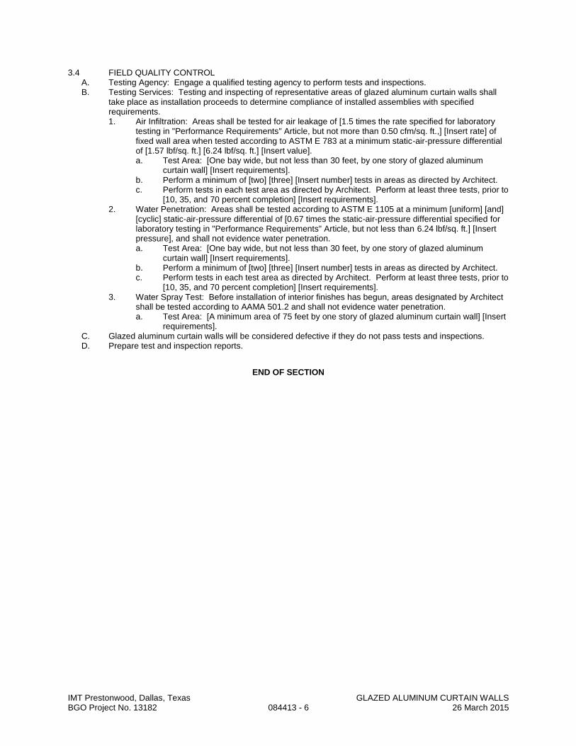
IMT Prestonwood, Dallas, Texas GLAZED ALUMINUM CURTAIN WALLS BGO Project No. 13182 084413 - 6 26 March 2015
3.4 FIELD QUALITY CONTROL A. Testing Agency: Engage a qualified testing agency to perform tests and inspections. B. Testing Services: Testing and inspecting of representative areas of glazed aluminum curtain walls shall
take place as installation proceeds to determine compliance of installed assemblies with specified requirements. 1. Air Infiltration: Areas shall be tested for air leakage of [1.5 times the rate specified for laboratory
testing in "Performance Requirements" Article, but not more than 0.50 cfm/sq. ft.,] [Insert rate] of fixed wall area when tested according to ASTM E 783 at a minimum static-air-pressure differential of [1.57 lbf/sq. ft.] [6.24 lbf/sq. ft.] [Insert value]. a. Test Area: [One bay wide, but not less than 30 feet, by one story of glazed aluminum
curtain wall] [Insert requirements]. b. Perform a minimum of [two] [three] [Insert number] tests in areas as directed by Architect. c. Perform tests in each test area as directed by Architect. Perform at least three tests, prior to
[10, 35, and 70 percent completion] [Insert requirements]. 2. Water Penetration: Areas shall be tested according to ASTM E 1105 at a minimum [uniform] [and]
[cyclic] static-air-pressure differential of [0.67 times the static-air-pressure differential specified for laboratory testing in "Performance Requirements" Article, but not less than 6.24 lbf/sq. ft.] [Insert pressure], and shall not evidence water penetration. a. Test Area: [One bay wide, but not less than 30 feet, by one story of glazed aluminum
curtain wall] [Insert requirements]. b. Perform a minimum of [two] [three] [Insert number] tests in areas as directed by Architect. c. Perform tests in each test area as directed by Architect. Perform at least three tests, prior to
[10, 35, and 70 percent completion] [Insert requirements]. 3. Water Spray Test: Before installation of interior finishes has begun, areas designated by Architect
shall be tested according to AAMA 501.2 and shall not evidence water penetration. a. Test Area: [A minimum area of 75 feet by one story of glazed aluminum curtain wall] [Insert
requirements]. C. Glazed aluminum curtain walls will be considered defective if they do not pass tests and inspections. D. Prepare test and inspection reports.
END OF SECTION

IMT Prestonwood, Dallas, Texas VINYL WINDOWS BGO Project No. 13182 085313 - 1 26 March 2015
SECTION 085313
VINYL WINDOWS
PART 1 - GENERAL
1.1 SECTION INCLUDES A. Factory fabricated tubular extruded plastic windows. B. Factory glazed including infill panels. C. Operating hardware. D. Insect screens. E. Perimeter sealant.
1.2 PERFORMANCE REQUIREMENTS A. Performance Requirements: As specified in PART 2, with the following additional requirements: B. Forced Entry Resistance: Conform to ASTM F 588 requirements for performance level 10 for window type
A. C. System Design: Design and size components to withstand dead and live loads caused by pressure and
suction of wind acting normal to plane of window. 1. Calculate design pressures in accordance with applicable code 2. Measure performance of units by testing in accordance with ASTM E 330, using test pressure
equal to 1.5 times the design wind pressure and 10 second duration of maximum load. D. Deflection: Limit member deflection to 1/200 of the longer dimension with full recovery of glazing
materials. E. Assembly: To accommodate, without damage to components or deterioration of seals, movement
between window and perimeter framing, deflection of lintel. F. Air Infiltration: Limit air infiltration through assembly to 0.3 cu ft/min/sq ft of wall area, measured at a
reference differential pressure across assembly of 1.57 psf as measured in accordance with ASTM E 283. G. Vapor Seal: No vapor seal failure at interior static pressure of 1 inch, 72 degrees F, and 40 percent
relative humidity. H. System Internal Drainage: Drain water entering joints, condensation occurring in glazing channels, or
migrating moisture occurring within system, to the exterior by a weep drainage network. I. Air and Vapor Seal: Maintain continuous air barrier and vapor retarder throughout assembly, primarily in
line with inside pane of glass and heel bead of glazing compound. Position thermal insulation on exterior surface of air barrier and vapor retarder.
J. Thermal Movement: Design sections to permit movement caused by thermal expansion and contraction of plastic to suit glass, infill, and perimeter opening construction.
K. Provide windows and doors with U value, SHGC, and SC values as required to meet energy code requirements.
1.3 SUBMITTALS A. See Section 013000 - Administrative Requirements, for submittal procedures. B. Product Data: Provide component dimensions, anchorage and fasteners, glass, internal drainage details. C. Shop Drawings: Indicate opening dimensions, framed opening tolerances, affected related work,
installation requirements. D. Samples: Submit two illustrating window frame section. E. Manufacturer's Certificate: Certify that products of this section meet or exceed specified requirements. F. Warranty: Submit manufacturer warranty and ensure that forms have been completed in Owner's name
and registered with manufacturer.
1.4 QUALITY ASSURANCE A. Manufacturer Qualifications: Company specializing in manufacturing products specified in this section,
with not less than three years of documented experience. B. Installer Qualifications: Company specializing in performing the work of this section with minimum three
years of experience.
1.5 DELIVERY, STORAGE, AND HANDLING A. Protect finished surfaces with wrapping. Do not use adhesive papers or sprayed coatings that bond when
exposed to sunlight or weather. B. Jig, brace, and box the window frame assemblies for transport to minimize flexing of members or joints.
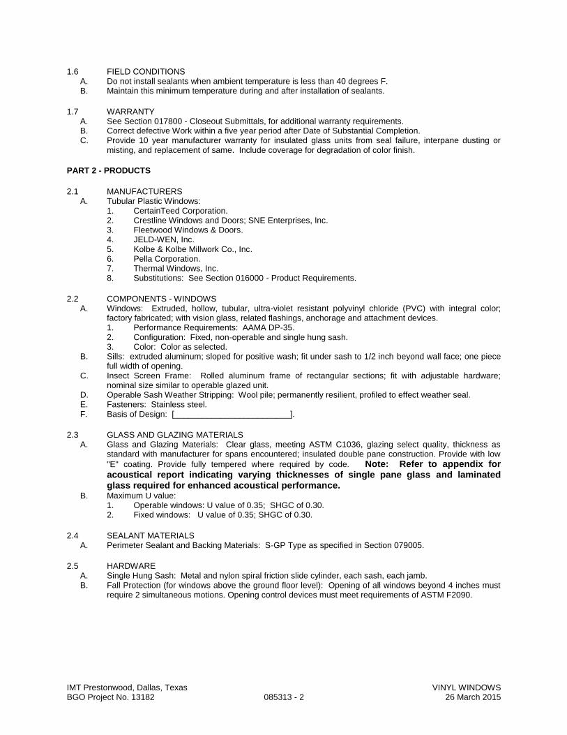
IMT Prestonwood, Dallas, Texas VINYL WINDOWS BGO Project No. 13182 085313 - 2 26 March 2015
1.6 FIELD CONDITIONS A. Do not install sealants when ambient temperature is less than 40 degrees F. B. Maintain this minimum temperature during and after installation of sealants.
1.7 WARRANTY A. See Section 017800 - Closeout Submittals, for additional warranty requirements. B. Correct defective Work within a five year period after Date of Substantial Completion. C. Provide 10 year manufacturer warranty for insulated glass units from seal failure, interpane dusting or
misting, and replacement of same. Include coverage for degradation of color finish.
PART 2 - PRODUCTS
2.1 MANUFACTURERS A. Tubular Plastic Windows:
1. CertainTeed Corporation. 2. Crestline Windows and Doors; SNE Enterprises, Inc. 3. Fleetwood Windows & Doors. 4. JELD-WEN, Inc. 5. Kolbe & Kolbe Millwork Co., Inc. 6. Pella Corporation. 7. Thermal Windows, Inc. 8. Substitutions: See Section 016000 - Product Requirements.
2.2 COMPONENTS - WINDOWS A. Windows: Extruded, hollow, tubular, ultra-violet resistant polyvinyl chloride (PVC) with integral color;
factory fabricated; with vision glass, related flashings, anchorage and attachment devices. 1. Performance Requirements: AAMA DP-35. 2. Configuration: Fixed, non-operable and single hung sash. 3. Color: Color as selected.
B. Sills: extruded aluminum; sloped for positive wash; fit under sash to 1/2 inch beyond wall face; one piece full width of opening.
C. Insect Screen Frame: Rolled aluminum frame of rectangular sections; fit with adjustable hardware; nominal size similar to operable glazed unit.
D. Operable Sash Weather Stripping: Wool pile; permanently resilient, profiled to effect weather seal. E. Fasteners: Stainless steel. F. Basis of Design: [_________________________].
2.3 GLASS AND GLAZING MATERIALS A. Glass and Glazing Materials: Clear glass, meeting ASTM C1036, glazing select quality, thickness as
standard with manufacturer for spans encountered; insulated double pane construction. Provide with low
"E" coating. Provide fully tempered where required by code. Note: Refer to appendix for acoustical report indicating varying thicknesses of single pane glass and laminated glass required for enhanced acoustical performance.
B. Maximum U value: 1. Operable windows: U value of 0.35; SHGC of 0.30. 2. Fixed windows: U value of 0.35; SHGC of 0.30.
2.4 SEALANT MATERIALS A. Perimeter Sealant and Backing Materials: S-GP Type as specified in Section 079005.
2.5 HARDWARE A. Single Hung Sash: Metal and nylon spiral friction slide cylinder, each sash, each jamb. B. Fall Protection (for windows above the ground floor level): Opening of all windows beyond 4 inches must
require 2 simultaneous motions. Opening control devices must meet requirements of ASTM F2090.

IMT Prestonwood, Dallas, Texas VINYL WINDOWS BGO Project No. 13182 085313 - 3 26 March 2015
2.6 FABRICATION A. Fabricate framing, mullions and sash members with fusion welded corners and joints, in a rigid jig.
Supplement frame sections with internal reinforcement where required for structural rigidity. B. Form sills and stools in one piece. Slope sills for wash. C. Form snap-in glass stops, closure molds, weather stops, and flashings of extruded PVC for tight fit into
window frame section. D. Form weather stop flange to perimeter of unit. E. Fabricate components with minimum clearances and shim spacing around perimeter of assembly, yet
enabling installation and dynamic movement of perimeter seal. F. Arrange fasteners to be concealed from view. G. Permit internal drainage weep holes and channels to migrate moisture to exterior. Provide internal
drainage of glazing spaces to exterior through weep holes. H. Assemble insect screen frame, miter and reinforced frame corners. Fit mesh taut into frame and secure.
Fit frame with four spring loaded steel pin retainers. I. Double weatherstrip operable units. J. Factory glaze window units.
PART 3 - EXECUTION
3.1 EXAMINATION A. Verify wall openings and adjoining air and vapor seal materials are ready to receive work of this Section.
3.2 INSTALLATION A. Install window units in accordance with manufacturers instructions. B. Attach window frame and shims to perimeter opening to accommodate construction tolerances and other
irregularities. C. Align window plumb and level, free of warp or twist. Maintain dimensional tolerances and alignment with
adjacent work. D. Install sill. E. Provide thermal isolation where components penetrate or disrupt building insulation. Pack fibrous
insulation in shim spaces at perimeter of assembly to maintain continuity of thermal barrier. F. Coordinate attachment and seal of perimeter air and vapor barrier materials. G. Install perimeter sealant and backing materials in accordance with Section 079005.
3.3 TOLERANCES A. Maximum Variation from Level or Plumb: 0.06 inches every 3 ft non-cumulative or 0.5 inches per 100 ft,
whichever is less.
3.4 ADJUSTING A. Adjust hardware for smooth operation and secure weathertight closure.
3.5 CLEANING A. Remove protective material from pre-finished surfaces. B. Wash surfaces by method recommended and acceptable to sealant and window manufacturer; rinse and
wipe surfaces clean. C. Remove excess sealant by moderate use of mineral spirits or other solvent acceptable to sealant
manufacturer.
END OF SECTION

IMT Prestonwood, Dallas, Texas DOOR HARDWARE BGO Project No. 13182 087100 - 1 26 March 2015
SECTION 087100
DOOR HARDWARE
PART 1 - GENERAL
1.1 SECTION INCLUDES A. Furnish, install, check, and service items of finish hardware for wood and hollow steel doors.
1.2 COORDINATION A. Coordinate work of this Section with other directly affected Sections involving manufacturer of any internal
reinforcement for door hardware.
1.3 QUALITY ASSURANCE A. Manufacturers: Companies specializing in manufacturing door hardware with minimum 3 years
experience. B. Hardware Supplier: Company specializing in supplying door hardware with 2 years experience. C. Hardware Installer: Employ a qualified carpentry person to perform the work of this Section. D. Manufacturers: Items of other manufacturers than those scheduled will be acceptable for substitution
provided they meet the quality standards of this Specification for finish, function and grade and substitution requests are made in accordance with Section 016000.
1.4 REGULATORY REQUIREMENTS A. Conform to applicable building code for requirements applicable to fire rated doors and frames. B. Conform to the applicable sections of Chapter 5 of NFPA 101, NFPA 80, and NFPA 252. C. Comply with provisions of ANSI A117.1 and local amendments (whichever is most stringent), to
accommodate handicapped persons. D. Provide hardware which has been tested and listed by UL or FM for fire rated assemblies of types which
comply with requirements of door and frame labels. E. Comply with governing laws and ordinances.
1.5 SUBMITTAL A. Submit schedule, shop drawings, and product data under provisions of Section 013000. B. Indicate locations and mounting heights of each type of hardware. C. Provide product data on specified hardware.
1.6 PROJECT RECORD DOCUMENTS A. Submit under provisions of Section 017800. B. Record actual locations of installed cylinders and their master key code.
1.7 OPERATION AND MAINTENANCE DATA A. Submit operation and maintenance data under provisions of Section 017800. B. Include data on operating hardware, lubrication requirements, and inspection procedures related to
preventative maintenance.
1.8 DELIVERY, STORAGE, AND HANDLING A. Deliver products to site under provisions of Section 016000. B. Store and protect products under provisions of Section 016000. C. Package hardware items individually; label and identify package with door opening code to match
hardware schedule. D. Deliver permanent keys to Owner direct from hardware supplier. E. Protect hardware from theft by cataloging and storing in secure area.
1.9 COORDINATION A. Coordinate work under provisions of Section 017000. B. Coordinate the work with other directly affected sections involving manufacture or fabrication of internal
reinforcement for door hardware.
1.10 WARRANTY A. Provide manufacturer's standard warranty under provisions of Section 017800.
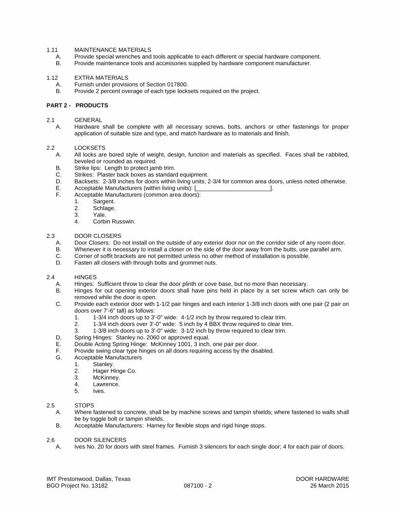
IMT Prestonwood, Dallas, Texas DOOR HARDWARE BGO Project No. 13182 087100 - 2 26 March 2015
1.11 MAINTENANCE MATERIALS A. Provide special wrenches and tools applicable to each different or special hardware component. B. Provide maintenance tools and accessories supplied by hardware component manufacturer.
1.12 EXTRA MATERIALS A. Furnish under provisions of Section 017800. B. Provide 2 percent overage of each type locksets required on the project.
PART 2 - PRODUCTS
2.1 GENERAL A. Hardware shall be complete with all necessary screws, bolts, anchors or other fastenings for proper
application of suitable size and type, and match hardware as to materials and finish.
2.2 LOCKSETS A. All locks are bored style of weight, design, function and materials as specified. Faces shall be rabbited,
beveled or rounded as required. B. Strike lips: Length to protect jamb trim. C. Strikes: Plaster back boxes as standard equipment. D. Backsets: 2-3/8 inches for doors within living units; 2-3/4 for common area doors, unless noted otherwise. E. Acceptable Manufacturers (within living units): [_______________________]. F. Acceptable Manufacturers (common area doors):
1. Sargent. 2. Schlage. 3. Yale. 4. Corbin Russwin.
2.3 DOOR CLOSERS A. Door Closers: Do not install on the outside of any exterior door nor on the corridor side of any room door. B. Whenever it is necessary to install a closer on the side of the door away from the butts, use parallel arm. C. Corner of soffit brackets are not permitted unless no other method of installation is possible. D. Fasten all closers with through bolts and grommet nuts.
2.4 HINGES A. Hinges: Sufficient throw to clear the door plinth or cove base, but no more than necessary. B. Hinges for out opening exterior doors shall have pins held in place by a set screw which can only be
removed while the door is open. C. Provide each exterior door with 1-1/2 pair hinges and each interior 1-3/8 inch doors with one pair (2 pair on
doors over 7'-6" tall) as follows: 1. 1-3/4 inch doors up to 3'-0" wide: 4-1/2 inch by throw required to clear trim. 2. 1-3/4 inch doors over 3'-0" wide: 5 inch by 4 BBX throw required to clear trim. 3. 1-3/8 inch doors up to 3'-0" wide: 3-1/2 inch by throw required to clear trim.
D. Spring Hinges: Stanley no. 2060 or approved equal. E. Double Acting Spring Hinge: McKinney 1001, 3 inch, one pair per door. F. Provide swing clear type hinges on all doors requiring access by the disabled. G. Acceptable Manufacturers
1. Stanley. 2. Hager Hinge Co. 3. McKinney. 4. Lawrence. 5. Ives.
2.5 STOPS A. Where fastened to concrete, shall be by machine screws and tampin shields; where fastened to walls shall
be by toggle bolt or tampin shields. B. Acceptable Manufacturers: Harney for flexible stops and rigid hinge stops.
2.6 DOOR SILENCERS A. Ives No. 20 for doors with steel frames. Furnish 3 silencers for each single door; 4 for each pair of doors.
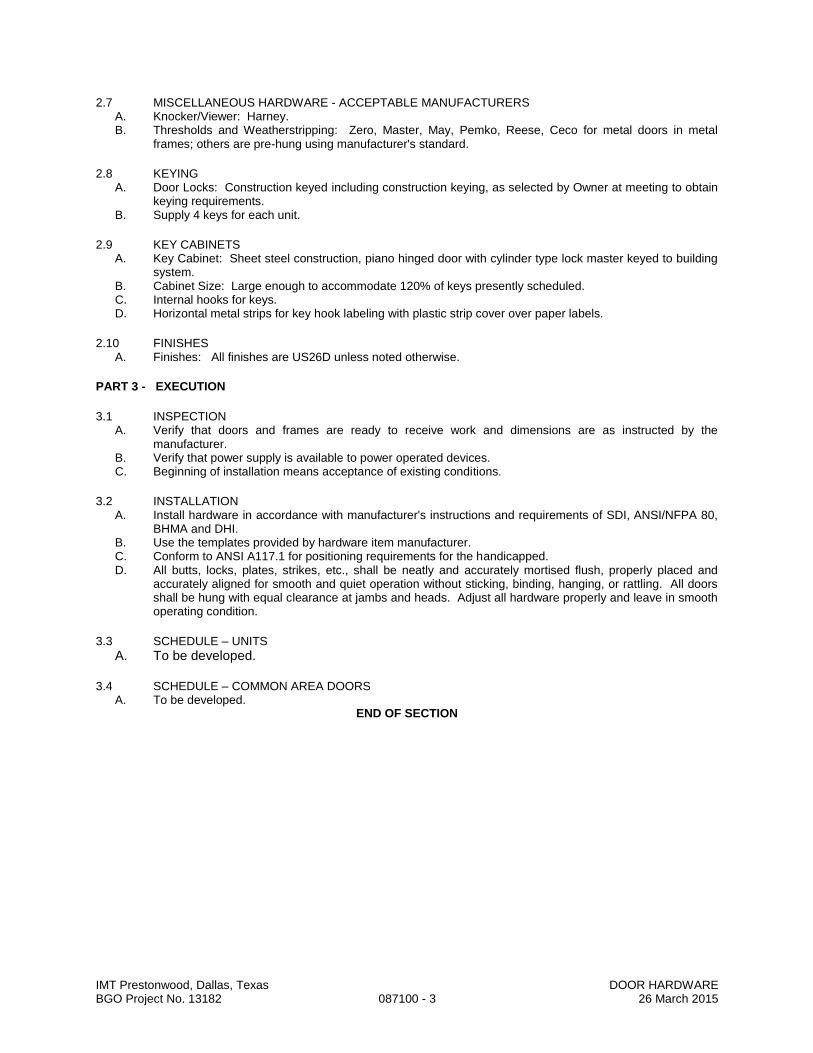
IMT Prestonwood, Dallas, Texas DOOR HARDWARE BGO Project No. 13182 087100 - 3 26 March 2015
2.7 MISCELLANEOUS HARDWARE - ACCEPTABLE MANUFACTURERS A. Knocker/Viewer: Harney. B. Thresholds and Weatherstripping: Zero, Master, May, Pemko, Reese, Ceco for metal doors in metal
frames; others are pre-hung using manufacturer's standard.
2.8 KEYING A. Door Locks: Construction keyed including construction keying, as selected by Owner at meeting to obtain
keying requirements. B. Supply 4 keys for each unit.
2.9 KEY CABINETS A. Key Cabinet: Sheet steel construction, piano hinged door with cylinder type lock master keyed to building
system. B. Cabinet Size: Large enough to accommodate 120% of keys presently scheduled. C. Internal hooks for keys. D. Horizontal metal strips for key hook labeling with plastic strip cover over paper labels.
2.10 FINISHES A. Finishes: All finishes are US26D unless noted otherwise.
PART 3 - EXECUTION
3.1 INSPECTION A. Verify that doors and frames are ready to receive work and dimensions are as instructed by the
manufacturer. B. Verify that power supply is available to power operated devices. C. Beginning of installation means acceptance of existing conditions.
3.2 INSTALLATION A. Install hardware in accordance with manufacturer's instructions and requirements of SDI, ANSI/NFPA 80,
BHMA and DHI. B. Use the templates provided by hardware item manufacturer. C. Conform to ANSI A117.1 for positioning requirements for the handicapped. D. All butts, locks, plates, strikes, etc., shall be neatly and accurately mortised flush, properly placed and
accurately aligned for smooth and quiet operation without sticking, binding, hanging, or rattling. All doors shall be hung with equal clearance at jambs and heads. Adjust all hardware properly and leave in smooth operating condition.
3.3 SCHEDULE – UNITS
A. To be developed.
3.4 SCHEDULE – COMMON AREA DOORS A. To be developed.
END OF SECTION
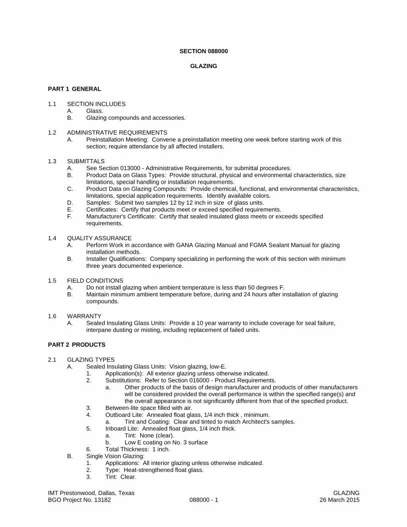
IMT Prestonwood, Dallas, Texas GLAZING BGO Project No. 13182 088000 - 1 26 March 2015
SECTION 088000
GLAZING
PART 1 GENERAL
1.1 SECTION INCLUDES A. Glass. B. Glazing compounds and accessories.
1.2 ADMINISTRATIVE REQUIREMENTS A. Preinstallation Meeting: Convene a preinstallation meeting one week before starting work of this
section; require attendance by all affected installers.
1.3 SUBMITTALS A. See Section 013000 - Administrative Requirements, for submittal procedures. B. Product Data on Glass Types: Provide structural, physical and environmental characteristics, size
limitations, special handling or installation requirements. C. Product Data on Glazing Compounds: Provide chemical, functional, and environmental characteristics,
limitations, special application requirements. Identify available colors. D. Samples: Submit two samples 12 by 12 inch in size of glass units. E. Certificates: Certify that products meet or exceed specified requirements. F. Manufacturer's Certificate: Certify that sealed insulated glass meets or exceeds specified
requirements.
1.4 QUALITY ASSURANCE A. Perform Work in accordance with GANA Glazing Manual and FGMA Sealant Manual for glazing
installation methods. B. Installer Qualifications: Company specializing in performing the work of this section with minimum
three years documented experience.
1.5 FIELD CONDITIONS A. Do not install glazing when ambient temperature is less than 50 degrees F. B. Maintain minimum ambient temperature before, during and 24 hours after installation of glazing
compounds.
1.6 WARRANTY A. Sealed Insulating Glass Units: Provide a 10 year warranty to include coverage for seal failure,
interpane dusting or misting, including replacement of failed units.
PART 2 PRODUCTS
2.1 GLAZING TYPES A. Sealed Insulating Glass Units: Vision glazing, low-E.
1. Application(s): All exterior glazing unless otherwise indicated. 2. Substitutions: Refer to Section 016000 - Product Requirements.
a. Other products of the basis of design manufacturer and products of other manufacturers will be considered provided the overall performance is within the specified range(s) and the overall appearance is not significantly different from that of the specified product.
3. Between-lite space filled with air. 4. Outboard Lite: Annealed float glass, 1/4 inch thick , minimum.
a. Tint and Coating: Clear and tinted to match Architect's samples. 5. Inboard Lite: Annealed float glass, 1/4 inch thick.
a. Tint: None (clear). b. Low E coating on No. 3 surface
6. Total Thickness: 1 inch. B. Single Vision Glazing:
1. Applications: All interior glazing unless otherwise indicated. 2. Type: Heat-strengthened float glass. 3. Tint: Clear.

IMT Prestonwood, Dallas, Texas GLAZING BGO Project No. 13182 088000 - 2 26 March 2015
4. Thickness: 1/4 inch. C. Fire-Rated Safety Glazing:
1. Applications: Provide this type of glazing in the following locations: a. Glazed lites in fire doors. b. Sidelights, borrow lites, and other glazed openings in partitions indicated as having an
hourly fire rating. 2. Fire Rating: As indicated on the drawings. 3. Type: Glass-ceramic safety glazing. 4. Thickness: 1/4 inch.
D. Single Safety Glazing: Non-fire-rated. 1. Applications: Provide this type of glazing in the following locations:
a. Glazed lites in doors, except fire doors. b. Glazed sidelights to doors, except in fire-rated walls and partitions. c. Other locations required by applicable federal, state, and local codes and regulations. d. Other locations indicated on the drawings.
2. Type: Fully tempered float glass as specified. 3. Tint: Clear. 4. Thickness: 1/4 inch.
2.2 EXTERIOR GLAZING ASSEMBLIES A. Structural Design Criteria: Select type and thickness to withstand dead loads and wind loads acting
normal to plane of glass at design pressures calculated in accordance with local code. 1. Use the procedure specified in ASTM E1300 to determine glass type and thickness. 2. Limit glass deflection to 1/200 or flexure limit of glass, whichever is less, with full recovery of
glazing materials. 3. Thicknesses listed are minimum.
2.3 GLASS MATERIALS A. Float Glass Manufacturers:
1. AGC Flat Glass North America, Inc: www.na.agc-flatglass.com. 2. Guardian Industries Corp: www.sunguardglass.com. 3. Pilkington North America Inc: www.pilkington.com/na. 4. PPG Industries, Inc: www.ppgideascapes.com. 5. Substitutions: Refer to Section 016000 - Product Requirements.
B. Float Glass: All glazing is to be float glass unless otherwise indicated. 1. Annealed Type: ASTM C1036, Type I, transparent flat, Class 1 clear, Quality Q3 (glazing
select). 2. Heat-Strengthened and Fully Tempered Types: ASTM C1048. 3. Tinted Types: Color and performance characteristics as indicated. 4. Thicknesses: As indicated; for exterior glazing comply with specified requirements for wind
load design regardless of specified thickness. C. Glass-Ceramic Safety Glazing: UL- or WH-listed as fire-protection-rated glazing and complying with 16
CFR 1201 test requirements for Category II without the use of a surface-applied film.
2.4 SEALED INSULATING GLASS UNITS A. Manufacturers:
1. Cardinal Glass Industries: www.cardinalcorp.com. 2. Guardian Industries Corporation: www.guardian.com. 3. Viracon, Apogee Enterprises, Inc: www.viracon.com. 4. Substitutions: Refer to Section 016000 - Product Requirements.
B. Sealed Insulating Glass Units: Types as indicated. 1. Locations: Exterior, except as otherwise indicated. 2. Durability: Certified by an independent testing agency to comply with ASTM E2190. 3. Edge Spacers: Aluminum, bent and soldered corners. 4. Edge Seal: Glass to elastomer with supplementary silicone sealant. 5. Purge interpane space with dry hermetic air.
At spandrel locations, provide same unit as at vision glass except for opacifier on no. 3 surface in color as selected by Architect.
6. Thermal Performance: Maximum 0.60 U value; 0.30 SHGC. 7. Refer to appendix for acoustical report indicating varying thicknesses of single pane
glass and laminated glass required for enhanced acoustical performance.
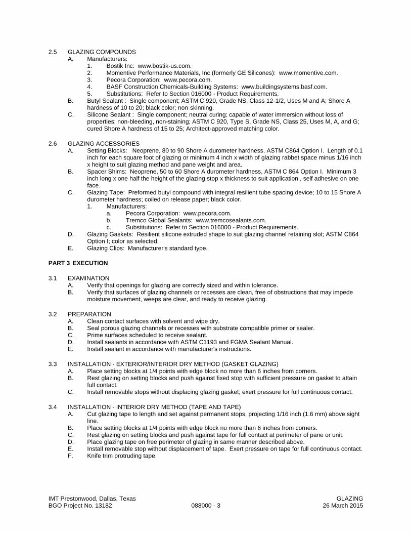
IMT Prestonwood, Dallas, Texas GLAZING BGO Project No. 13182 088000 - 3 26 March 2015
2.5 GLAZING COMPOUNDS A. Manufacturers:
1. Bostik Inc: www.bostik-us.com. 2. Momentive Performance Materials, Inc (formerly GE Silicones): www.momentive.com. 3. Pecora Corporation: www.pecora.com. 4. BASF Construction Chemicals-Building Systems: www.buildingsystems.basf.com. 5. Substitutions: Refer to Section 016000 - Product Requirements.
B. Butyl Sealant : Single component; ASTM C 920, Grade NS, Class 12-1/2, Uses M and A; Shore A hardness of 10 to 20; black color; non-skinning.
C. Silicone Sealant : Single component; neutral curing; capable of water immersion without loss of properties; non-bleeding, non-staining; ASTM C 920, Type S, Grade NS, Class 25, Uses M, A, and G; cured Shore A hardness of 15 to 25; Architect-approved matching color.
2.6 GLAZING ACCESSORIES A. Setting Blocks: Neoprene, 80 to 90 Shore A durometer hardness, ASTM C864 Option I. Length of 0.1
inch for each square foot of glazing or minimum 4 inch x width of glazing rabbet space minus 1/16 inch x height to suit glazing method and pane weight and area.
B. Spacer Shims: Neoprene, 50 to 60 Shore A durometer hardness, ASTM C 864 Option I. Minimum 3 inch long x one half the height of the glazing stop x thickness to suit application , self adhesive on one face.
C. Glazing Tape: Preformed butyl compound with integral resilient tube spacing device; 10 to 15 Shore A durometer hardness; coiled on release paper; black color. 1. Manufacturers:
a. Pecora Corporation: www.pecora.com. b. Tremco Global Sealants: www.tremcosealants.com. c. Substitutions: Refer to Section 016000 - Product Requirements.
D. Glazing Gaskets: Resilient silicone extruded shape to suit glazing channel retaining slot; ASTM C864 Option I; color as selected.
E. Glazing Clips: Manufacturer's standard type.
PART 3 EXECUTION
3.1 EXAMINATION A. Verify that openings for glazing are correctly sized and within tolerance. B. Verify that surfaces of glazing channels or recesses are clean, free of obstructions that may impede
moisture movement, weeps are clear, and ready to receive glazing.
3.2 PREPARATION A. Clean contact surfaces with solvent and wipe dry. B. Seal porous glazing channels or recesses with substrate compatible primer or sealer. C. Prime surfaces scheduled to receive sealant. D. Install sealants in accordance with ASTM C1193 and FGMA Sealant Manual. E. Install sealant in accordance with manufacturer's instructions.
3.3 INSTALLATION - EXTERIOR/INTERIOR DRY METHOD (GASKET GLAZING) A. Place setting blocks at 1/4 points with edge block no more than 6 inches from corners. B. Rest glazing on setting blocks and push against fixed stop with sufficient pressure on gasket to attain
full contact. C. Install removable stops without displacing glazing gasket; exert pressure for full continuous contact.
3.4 INSTALLATION - INTERIOR DRY METHOD (TAPE AND TAPE) A. Cut glazing tape to length and set against permanent stops, projecting 1/16 inch (1.6 mm) above sight
line. B. Place setting blocks at 1/4 points with edge block no more than 6 inches from corners. C. Rest glazing on setting blocks and push against tape for full contact at perimeter of pane or unit. D. Place glazing tape on free perimeter of glazing in same manner described above. E. Install removable stop without displacement of tape. Exert pressure on tape for full continuous contact. F. Knife trim protruding tape.

IMT Prestonwood, Dallas, Texas GLAZING BGO Project No. 13182 088000 - 4 26 March 2015
3.5 INSTALLATION - INTERIOR WET/DRY METHOD (TAPE AND SEALANT) A. Cut glazing tape to length and install against permanent stops, projecting 1/16 inch (1.6 mm) above
sight line. B. Place setting blocks at 1/4 points with edge block no more than 6 inches from corners. C. Rest glazing on setting blocks and push against tape to ensure full contact at perimeter of pane or unit. D. Install removable stops, spacer shims inserted between glazing and applied stops at 24 inch intervals,
1/4 inch below sight line. E. Fill gaps between pane and applied stop with sealant to depth equal to bite on glazing, to uniform and
level line. F. Trim protruding tape edge.
3.6 CLEANING A. Remove glazing materials from finish surfaces. B. Remove labels after Work is complete. C. Clean glass and adjacent surfaces.
3.7 PROTECTION A. After installation, mark pane with an 'X' by using removable plastic tape or paste ; do not mark heat
absorbing or reflective glass units.
END OF SECTION

IMT Prestonwood, Dallas, Texas MIRRORS BGO Project No. 13182 088300 - 1 26 March 2015
SECTION 088300
MIRRORS
PART 1 GENERAL
1.1 SECTION INCLUDES A. Glass mirrors.
1.2 SUBMITTALS A. See Section 013000 - Administrative Requirements, for submittal procedures. B. Product Data on Mirror Types: Provide structural, physical and environmental characteristics, size
limitations, special handling or installation requirements. C. Manufacturer's Certificate: Certify that mirrors, meets or exceeds specified requirements. D. Warranty: Submit manufacturer warranty and ensure that forms have been completed in Owner's
name and registered with manufacturer.
1.3 QUALITY ASSURANCE A. Perform Work in accordance with GANA Glazing Manual for glazing installation methods. B. Fabricate, store, transport, receive, install, and clean mirrors in accordance with recommendations of
GANA (TIPS) "Mirrors Handle with Extreme Care: Tips For the Professional on the Care and Handling of Mirrors."
1.4 FIELD CONDITIONS A. Do not install mirrors when ambient temperature is less than 50 degrees F. B. Maintain minimum ambient temperature before, during and 24 hours after installation of glazing
compounds.
1.5 WARRANTY A. See Section 017800 - Closeout Submittals, for additional warranty requirements. B. Provide five year manufacturer warranty for reflective coating on mirrors and replacement of same.
PART 2 PRODUCTS
2.1 MANUFACTURERS A. Mirrors:
1. Binswanger Mirror/ACI Distribution: www.binswangerglass.com. 2. Lenoir Mirror Co: www.lenoirmirror.com. 3. Substitutions: See Section 016000 - Product Requirements.
2.2 MATERIALS A. Mirror Glass - General: Select materials and/or provide supports as required to limit mirrored glass
deflection to 1/200 or flexure limit of glass with full recovery of glazing materials, whichever is less. B. Mirror Glass: ASTM C1036, Type 1 transparent flat, Class 1 clear, Quality Q1 (mirror select); silvering,
protective coating and physical characteristics complying with ASTM C1503; 6 mm minimum thick. 1. Sizes noted on Drawings.
2.3 GLAZING ACCESSORIES A. Glazing Clips: Manufacturer's standard type. B. Mirror Attachment Accessories: Stainless steel clips. C. Mirror Adhesive: Chemically compatible with mirror coating and wall substrate.
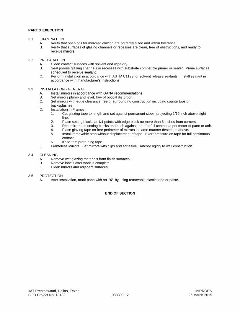
IMT Prestonwood, Dallas, Texas MIRRORS BGO Project No. 13182 088300 - 2 26 March 2015
PART 3 EXECUTION
3.1 EXAMINATION A. Verify that openings for mirrored glazing are correctly sized and within tolerance. B. Verify that surfaces of glazing channels or recesses are clean, free of obstructions, and ready to
receive mirrors.
3.2 PREPARATION A. Clean contact surfaces with solvent and wipe dry. B. Seal porous glazing channels or recesses with substrate compatible primer or sealer. Prime surfaces
scheduled to receive sealant. C. Perform installation in accordance with ASTM C1193 for solvent release sealants. Install sealant in
accordance with manufacturer's instructions.
3.3 INSTALLATION - GENERAL A. Install mirrors in accordance with GANA recommendations. B. Set mirrors plumb and level, free of optical distortion. C. Set mirrors with edge clearance free of surrounding construction including countertops or
backsplashes. D. Installation in Frames:
1. Cut glazing tape to length and set against permanent stops, projecting 1/16 inch above sight line.
2. Place setting blocks at 1/4 points with edge block no more than 6 inches from corners. 3. Rest mirrors on setting blocks and push against tape for full contact at perimeter of pane or unit. 4. Place glazing tape on free perimeter of mirrors in same manner described above. 5. Install removable stop without displacement of tape. Exert pressure on tape for full continuous
contact. 6. Knife-trim protruding tape.
E. Frameless Mirrors: Set mirrors with clips and adhesive. Anchor rigidly to wall construction.
3.4 CLEANING A. Remove wet glazing materials from finish surfaces. B. Remove labels after work is complete. C. Clean mirrors and adjacent surfaces.
3.5 PROTECTION A. After installation, mark pane with an 'X' by using removable plastic tape or paste.
END OF SECTION

IMT Prestonwood, Dallas, Texas GYPSUM BOARD ASSEMBLIES BGO Project No. 13182 092116 - 1 26 March 2015
SECTION 092116
GYPSUM BOARD ASSEMBLIES
PART 1 GENERAL
1.1 SECTION INCLUDES
A. Performance criteria for gypsum board assemblies.
B. Metal stud wall framing.
C. Gypsum wallboard.
D. Joint treatment and accessories.
E. Textured finish system.
1.2 QUALITY ASSURANCE
A. Installer Qualifications: Company specializing in performing gypsum board application and finishing , with minimum three years of documented experience.
1.3 SUBMITTALS A. Submit under provisions of Section 013000. B. Product Data: Provide data on metal framing, gypsum board, joint tape and joint compound. C. Submit manufacturer's installation instructions for each product proposed for use.
PART 2 PRODUCTS
2.1 GYPSUM BOARD ASSEMBLIES
A. Provide completed assemblies complying with ASTM C840 and GA-216.
B. Interior Partitions Indicated as Acoustic: Provide completed assemblies with the following characteristics:
1. Acoustic Attenuation: STC of 45-49 calculated in accordance with ASTM E413, based on tests conducted in accordance with ASTM E90.
C. Shaft Walls at HVAC Shafts: Provide completed assemblies with the following characteristics:
1. Air Pressure Within Shaft: Sustained loads of 5 lbf/sq ft with maximum mid-span deflection of L/240.
2. Acoustic Attenuation: STC of 35-39 calculated in accordance with ASTM E413, based on tests conducted in accordance with ASTM E90.
D. Shaft Walls at Elevator Shafts: Provide completed assemblies with the following characteristics:
1. Air Pressure Within Shaft: Intermittent loads of 5 lbf/sq ft with maximum mid-span deflection of L/240.
2. Acoustic Attenuation: STC of 35-39 calculated in accordance with ASTM E413, based on tests conducted in accordance with ASTM E90.
E. Fire Rated Assemblies: Provide completed assemblies with the following characteristics:
1. UL Assembly Numbers: Provide construction equivalent to that listed for the particular assembly in the current UL Fire Resistance Directory.
2.2 METAL FRAMING MATERIALS
A. Manufacturers - Metal Framing, Connectors, and Accessories:
1. Clarkwestern Dietrich Building Systems LLC : www.clarkdietrich.com.
2. Marino : www.marinoware.com.
3. Phillips Manufacturing Company : www.phillipsmfg.com.
4. Substitutions: See Section 016000 - Product Requirements.
B. Non-Loadbearing Framing System Components: ASTM C645; galvanized sheet steel, of size and properties necessary to comply with ASTM C754 for the spacing indicated, with maximum deflection of wall framing of L/240 at 5 psf.
1. Studs: "C" shaped with flat or formed webs with knurled faces.
2. Runners: U shaped, sized to match studs.
3. Furring: Hat-shaped sections, minimum depth of 7/8 inch.
C. Shaft Wall Studs and Accessories: ASTM C645; galvanized sheet steel, of size and properties necessary to comply with ASTM C754 and specified performance requirements.
1. Manufacturers - Shaft Wall Studs and Accessories:
a. Same manufacturer as other framing materials.
b. Substitutions: See Section 016000 - Product Requirements.
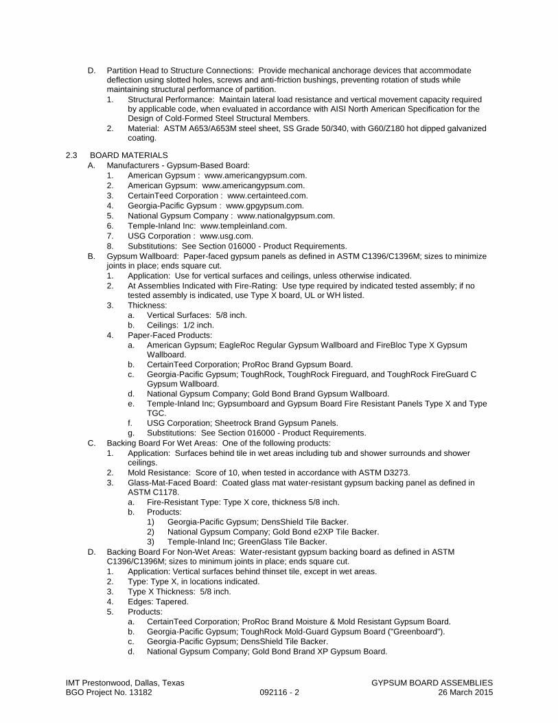
IMT Prestonwood, Dallas, Texas GYPSUM BOARD ASSEMBLIES BGO Project No. 13182 092116 - 2 26 March 2015
D. Partition Head to Structure Connections: Provide mechanical anchorage devices that accommodate deflection using slotted holes, screws and anti-friction bushings, preventing rotation of studs while maintaining structural performance of partition.
1. Structural Performance: Maintain lateral load resistance and vertical movement capacity required by applicable code, when evaluated in accordance with AISI North American Specification for the Design of Cold-Formed Steel Structural Members.
2. Material: ASTM A653/A653M steel sheet, SS Grade 50/340, with G60/Z180 hot dipped galvanized coating.
2.3 BOARD MATERIALS
A. Manufacturers - Gypsum-Based Board:
1. American Gypsum : www.americangypsum.com.
2. American Gypsum: www.americangypsum.com.
3. CertainTeed Corporation : www.certainteed.com.
4. Georgia-Pacific Gypsum : www.gpgypsum.com.
5. National Gypsum Company : www.nationalgypsum.com.
6. Temple-Inland Inc: www.templeinland.com.
7. USG Corporation : www.usg.com.
8. Substitutions: See Section 016000 - Product Requirements.
B. Gypsum Wallboard: Paper-faced gypsum panels as defined in ASTM C1396/C1396M; sizes to minimize joints in place; ends square cut.
1. Application: Use for vertical surfaces and ceilings, unless otherwise indicated.
2. At Assemblies Indicated with Fire-Rating: Use type required by indicated tested assembly; if no tested assembly is indicated, use Type X board, UL or WH listed.
3. Thickness:
a. Vertical Surfaces: 5/8 inch.
b. Ceilings: 1/2 inch.
4. Paper-Faced Products:
a. American Gypsum; EagleRoc Regular Gypsum Wallboard and FireBloc Type X Gypsum Wallboard.
b. CertainTeed Corporation; ProRoc Brand Gypsum Board.
c. Georgia-Pacific Gypsum; ToughRock, ToughRock Fireguard, and ToughRock FireGuard C Gypsum Wallboard.
d. National Gypsum Company; Gold Bond Brand Gypsum Wallboard.
e. Temple-Inland Inc; Gypsumboard and Gypsum Board Fire Resistant Panels Type X and Type TGC.
f. USG Corporation; Sheetrock Brand Gypsum Panels.
g. Substitutions: See Section 016000 - Product Requirements.
C. Backing Board For Wet Areas: One of the following products:
1. Application: Surfaces behind tile in wet areas including tub and shower surrounds and shower ceilings.
2. Mold Resistance: Score of 10, when tested in accordance with ASTM D3273.
3. Glass-Mat-Faced Board: Coated glass mat water-resistant gypsum backing panel as defined in ASTM C1178.
a. Fire-Resistant Type: Type X core, thickness 5/8 inch.
b. Products:
1) Georgia-Pacific Gypsum; DensShield Tile Backer.
2) National Gypsum Company; Gold Bond e2XP Tile Backer.
3) Temple-Inland Inc; GreenGlass Tile Backer.
D. Backing Board For Non-Wet Areas: Water-resistant gypsum backing board as defined in ASTM C1396/C1396M; sizes to minimum joints in place; ends square cut.
1. Application: Vertical surfaces behind thinset tile, except in wet areas.
2. Type: Type X, in locations indicated.
3. Type X Thickness: 5/8 inch.
4. Edges: Tapered.
5. Products:
a. CertainTeed Corporation; ProRoc Brand Moisture & Mold Resistant Gypsum Board.
b. Georgia-Pacific Gypsum; ToughRock Mold-Guard Gypsum Board ("Greenboard").
c. Georgia-Pacific Gypsum; DensShield Tile Backer.
d. National Gypsum Company; Gold Bond Brand XP Gypsum Board.

IMT Prestonwood, Dallas, Texas GYPSUM BOARD ASSEMBLIES BGO Project No. 13182 092116 - 3 26 March 2015
e. Temple-Inland Inc; ComfortGuard WR.
f. USG Corporation; Sheetrock Brand Mold Tough Gypsum Panels.
E. Ceiling Board: Special sag-resistant gypsum ceiling board as defined in ASTM C1396/C1396M; sizes to minimize joints in place; ends square cut.
1. Application: Ceilings, unless otherwise indicated.
2. Thickness: 1/2 inch.
3. Edges: Tapered.
4. Products:
a. American Gypsum; Interior Ceiling Board.
b. CertainTeed Corporation; ProRoc Interior Ceiling.
c. Georgia-Pacific Gypsum; ToughRock CD Ceiling Board.
d. National Gypsum Company; High Strength Brand Ceiling Board.
e. Temple-Inland Inc; Span24 Ceiling Board.
f. USG Corporation; Sheetrock Brand Sag-Resistant Interior Gypsum Ceiling Board.
g. Substitutions: See Section 016000 - Product Requirements.
F. Shaftwall and Coreboard: Type X; 1 inch thick by 24 inches wide, beveled long edges, ends square cut.
1. Paper Faced Type: Gypsum shaftliner board or gypsum coreboard as defined ASTM C1396/C1396M; water-resistant faces.
2. Products:
a. American Gypsum; Shaft Liner.
b. CertainTeed Corporation; ProRoc Brand Shaftliner Type X.
c. National Gypsum Company; Gold Bond Brand 1" Fire-Shield Shaftliner.
d. National Gypsum Company; Gold Bond Brand 1" Fire-Shield Shaftliner XP (mold-resistant).
e. Pacific Coast Building Products, Inc; PABCORE Gypsum Shaftliner Board type X.
f. Temple-Inland Inc; SilentGuard Gypsum Shaftliner.
g. USG Corporation; Sheetrock Gypsum Liner Panels.
h. USG Corporation; Sheetrock Gypsum Liner Panels--Enhanced (mold-resistant).
2.4 ACCESSORIES
A. Finishing Accessories: ASTM C1047, galvanized steel or rolled zinc, unless otherwise indicated.
1. Types: As detailed or required for finished appearance.
B. Joint Materials: ASTM C475 and as recommended by gypsum board manufacturer for project conditions.
1. Tape: 2 inch wide, coated glass fiber tape for joints and corners , except as otherwise indicated.
2. Tape: 2 inch wide, creased paper tape for joints and corners , except as otherwise indicated.
3. Ready-mixed vinyl-based joint compound.
4. Powder-type vinyl-based joint compound.
5. Chemical hardening type compound.
C. High Build Drywall Surfacer: Vinyl acrylic latex-based coating for spray application, designed to take the place of skim coating and separate paint primer in achieving Level 5 finish.
D. Textured Finish Materials: Latex-based compound; plain.
E. Screws for Attachment to Steel Members Less Than 0.03 inch In Thickness, to Wood Members, and to Gypsum Board: ASTM C1002; self-piercing tapping type ; cadmium-plated for exterior locations.
F. Screws for Attachment to Steel Members From 0.033 to 0.112 inch in Thickness: ASTM C954; steel drill screws for application of gypsum board to loadbearing steel studs.
PART 3 EXECUTION
3.1 EXAMINATION
A. Verify that project conditions are appropriate for work of this section to commence.
3.2 SHAFT WALL INSTALLATION
A. Shaft Wall Framing: Install in accordance with manufacturer's installation instructions.
1. Install studs at spacing required to meet performance requirements.
B. Shaft Wall Liner: Cut panels to accurate dimension and install sequentially between special friction studs.
1. On walls over sixteen feet high, screw-attach studs to runners top and bottom.
2. Seal perimeter of shaft wall and penetrations with acoustical sealant.
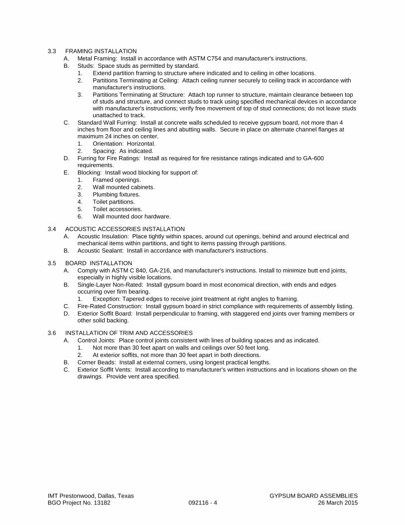
IMT Prestonwood, Dallas, Texas GYPSUM BOARD ASSEMBLIES BGO Project No. 13182 092116 - 4 26 March 2015
3.3 FRAMING INSTALLATION
A. Metal Framing: Install in accordance with ASTM C754 and manufacturer's instructions.
B. Studs: Space studs as permitted by standard.
1. Extend partition framing to structure where indicated and to ceiling in other locations.
2. Partitions Terminating at Ceiling: Attach ceiling runner securely to ceiling track in accordance with manufacturer's instructions.
3. Partitions Terminating at Structure: Attach top runner to structure, maintain clearance between top of studs and structure, and connect studs to track using specified mechanical devices in accordance with manufacturer's instructions; verify free movement of top of stud connections; do not leave studs unattached to track.
C. Standard Wall Furring: Install at concrete walls scheduled to receive gypsum board, not more than 4 inches from floor and ceiling lines and abutting walls. Secure in place on alternate channel flanges at maximum 24 inches on center.
1. Orientation: Horizontal.
2. Spacing: As indicated.
D. Furring for Fire Ratings: Install as required for fire resistance ratings indicated and to GA-600 requirements.
E. Blocking: Install wood blocking for support of:
1. Framed openings.
2. Wall mounted cabinets.
3. Plumbing fixtures.
4. Toilet partitions.
5. Toilet accessories.
6. Wall mounted door hardware.
3.4 ACOUSTIC ACCESSORIES INSTALLATION
A. Acoustic Insulation: Place tightly within spaces, around cut openings, behind and around electrical and mechanical items within partitions, and tight to items passing through partitions.
B. Acoustic Sealant: Install in accordance with manufacturer's instructions.
3.5 BOARD INSTALLATION
A. Comply with ASTM C 840, GA-216, and manufacturer's instructions. Install to minimize butt end joints, especially in highly visible locations.
B. Single-Layer Non-Rated: Install gypsum board in most economical direction, with ends and edges occurring over firm bearing.
1. Exception: Tapered edges to receive joint treatment at right angles to framing.
C. Fire-Rated Construction: Install gypsum board in strict compliance with requirements of assembly listing.
D. Exterior Soffit Board: Install perpendicular to framing, with staggered end joints over framing members or other solid backing.
3.6 INSTALLATION OF TRIM AND ACCESSORIES
A. Control Joints: Place control joints consistent with lines of building spaces and as indicated.
1. Not more than 30 feet apart on walls and ceilings over 50 feet long.
2. At exterior soffits, not more than 30 feet apart in both directions.
B. Corner Beads: Install at external corners, using longest practical lengths.
C. Exterior Soffit Vents: Install according to manufacturer's written instructions and in locations shown on the drawings. Provide vent area specified.
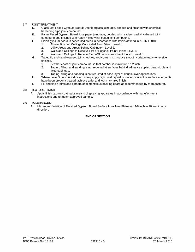
IMT Prestonwood, Dallas, Texas GYPSUM BOARD ASSEMBLIES BGO Project No. 13182 092116 - 5 26 March 2015
3.7 JOINT TREATMENT D. Glass Mat Faced Gypsum Board: Use fiberglass joint tape, bedded and finished with chemical
hardening type joint compound. E. Paper Faced Gypsum Board: Use paper joint tape, bedded with ready-mixed vinyl-based joint
compound and finished with ready-mixed vinyl-based joint compound. F. Finish gypsum board in scheduled areas in accordance with levels defined in ASTM C 840.
1. Above Finished Ceilings Concealed From View: Level 1. 2. Utility Areas and Areas Behind Cabinetry: Level 2. 3. Walls and Ceilings to Receive Flat or Eggshell Paint Finish: Level 4. 4. Walls and Ceilings to Receive Semi-Gloss or Gloss Paint Finish: Level 5.
G. Tape, fill, and sand exposed joints, edges, and corners to produce smooth surface ready to receive finishes. 1. Feather coats of joint compound so that camber is maximum 1/32 inch. 2. Taping, filling, and sanding is not required at surfaces behind adhesive applied ceramic tile and
fixed cabinetry. 3. Taping, filling and sanding is not required at base layer of double layer applications.
H. Where Level 5 finish is indicated, spray apply high build drywall surfacer over entire surface after joints have been properly treated; achieve a flat and tool mark-free finish.
I. Fill and finish joints and corners of cementitious backing board as recommended by manufacturer.
3.8 TEXTURE FINISH
A. Apply finish texture coating by means of spraying apparatus in accordance with manufacturer's instructions and to match approved sample.
3.9 TOLERANCES
A. Maximum Variation of Finished Gypsum Board Surface from True Flatness: 1/8 inch in 10 feet in any direction.
END OF SECTION

IMT Prestonwood, Dallas, Texas METAL LATH BGO Project No. 13182 092236 - 1 26 March 2015
SECTION 092236
METAL LATH
PART 1 GENERAL
1.1 SECTION INCLUDES A. Metal lath for Portland cement plaster. B. Furring for metal lath at ceiling/soffit applications without solid substrate.
1.2 REFERENCE STANDARDS A. ASTM C847 - Standard Specification for Metal Lath: 2012. B. ASTM C1002 - Standard Specification for Steel Self-Piercing Tapping Screws for the Application of
Gypsum Panel Products or Metal Plaster Bases to Wood Studs or Steel Studs: 2007.
1.3 SUBMITTALS A. See Section 013000 - Administrative Requirements, for submittal procedures. B. Product Data: Provide data on furring and lathing components, structural characteristics, material
limitations, and finish.
1.4 QUALITY ASSURANCE A. Installer Qualifications: Company specializing in performing the work of this section with minimum
three years experience.
PART 2 PRODUCTS
2.1 MANUFACTURERS A. Metal Lath:
1. Alabama Metal Industries Corporation : www.amico-online.com. 2. Cemco : www.cemcosteel.com. 3. Clarkwestern Dietrich Building System LLC : www.clarkdietrich.com. 4. Substitutions: See Section 016000 - Product Requirements.
2.2 FRAMING AND LATH ASSEMBLIES A. Provide completed assemblies with the following characteristics:
1. Maximum Deflection of Vertical Assemblies: 1:360 under lateral point load of 100 lbs. 2. Maximum Deflection of Horizontal Assemblies: 1:240 deflection under dead loads and wind
uplift.
2.3 FRAMING MATERIALS A. Furring Channels: Formed steel, minimum 0.020 inch thick, 3/8 inch deep x 7/8 inch high, splicing
permitted; galvanized. B. Main Ceiling Channels: Formed steel, asphalt coated, minimum 0.05 inch thick, 3/4 inch deep x 1-1/2
inch high, single piece, no splicing; galvanized. C. Hangers: Steel wire, of size and type to suit application, to support ceiling components in place to
deflection limits as indicated. D. Ceiling Hangers: Rolled steel sections, of size and type to suit application, to rigidly support ceiling
components in place to deflection limits as indicated; galvanized. E. Lateral Bracing: Formed steel, minimum 0.060 inch thick, size and length as required; galvanized.
2.4 LATH A. Diamond Mesh Metal Lath: ASTM C847, galvanized; self-furring.
1. Weight: 3.4 lb/sq yd. 2. Backed with treated paper.
B. Corner Mesh: Formed sheet steel, minimum 0.018 inch thick, perforated flanges shaped to permit complete embedding in plaster, minimum 2 inch size; same finish as lath.
C. Strip Mesh: Expanded metal lath, the same weight as lath, 2 inch wide x 24 inch long; same finish as lath.
D. Beads, Screeds, Joint Accessories, and Other Trim: Depth governed by plaster thickness, maximum possible lengths. 1. Material: PVC, open grid flanges or perforated with nailing holes.
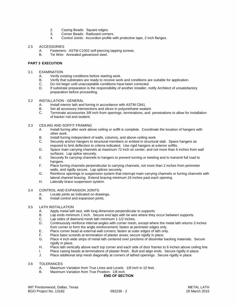
IMT Prestonwood, Dallas, Texas METAL LATH BGO Project No. 13182 092236 - 2 26 March 2015
2. Casing Beads: Square edges. 3. Corner Beads: Radiused corners. 4. Control Joints: Accordion profile with protective tape, 2 inch flanges.
2.5 ACCESSORIES A. Fasteners: ASTM C1002 self-piercing tapping screws. B. Tie Wire: Annealed galvanized steel.
PART 3 EXECUTION
3.1 EXAMINATION A. Verify existing conditions before starting work. B. Verify that substrates are ready to receive work and conditions are suitable for application. C. Do not begin until unacceptable conditions have been corrected. D. If substrate preparation is the responsibility of another installer, notify Architect of unsatisfactory
preparation before proceeding.
3.2 INSTALLATION - GENERAL A. Install interior lath and furring in accordance with ASTM C841. B. Set all accessory intersections and slices in polyurethane sealant. C. Terminate accessories 3/8 inch from openings, terminations, and penetrations to allow for installation
of backer rod and sealent.
3.3 CEILING AND SOFFIT FRAMING A. Install furring after work above ceiling or soffit is complete. Coordinate the location of hangers with
other work. B. Install furring independent of walls, columns, and above-ceiling work. C. Securely anchor hangers to structural members or embed in structural slab. Space hangers as
required to limit deflection to criteria indicated. Use rigid hangers at exterior soffits. D. Space main carrying channels at maximum 72 inch on center, and not more than 6 inches from wall
surfaces. Lap splice securely. E. Securely fix carrying channels to hangers to prevent turning or twisting and to transmit full load to
hangers. F. Place furring channels perpendicular to carrying channels, not more than 2 inches from perimeter
walls, and rigidly secure. Lap splices securely. G. Reinforce openings in suspension system that interrupt main carrying channels or furring channels with
lateral channel bracing. Extend bracing minimum 24 inches past each opening. H. Laterally brace suspension system.
3.4 CONTROL AND EXPANSION JOINTS A. Locate joints as indicated on drawings. B. Install control and expansion joints.
3.5 LATH INSTALLATION A. Apply metal lath taut, with long dimension perpendicular to supports. B. Lap ends minimum 1 inch. Secure end laps with tie wire where they occur between supports. C. Lap sides of diamond mesh lath minimum 1-1/2 inches. D. Continuously reinforce internal angles with corner mesh, except where the metal lath returns 3 inches
from corner to form the angle reinforcement; fasten at perimeter edges only. E. Place corner bead at external wall corners; fasten at outer edges of lath only. F. Place base screeds at termination of plaster areas; secure rigidly in place. G. Place 4 inch wide strips of metal lath centered over junctions of dissimilar backing materials. Secure
rigidly in place. H. Place lath vertically above each top corner and each side of door frames to 6 inches above ceiling line. I. Place casing beads at terminations of plaster finish. Butt and align ends. Secure rigidly in place. J. Place additional strip mesh diagonally at corners of lathed openings. Secure rigidly in place.
3.6 TOLERANCES A. Maximum Variation from True Lines and Levels: 1/8 inch in 10 feet. B. Maximum Variation from True Position: 1/8 inch.
END OF SECTION

IMT Prestonwood, Dallas, Texas PORTLAND CEMENT PLASTER – ONE COAT BGO Project No. 13182 092410 - 1 26 March 2015
SECTION 092410
PORTLAND CEMENT PLASTER – ONE COAT
PART 1 - GENERAL
1.1 SECTION INCLUDES A. Fiber reinforced portland cement plaster wall cladding.
1.2 QUALITY ASSURANCE A. Applicator: Company specializing in cement plaster work with 5 years documented experience. B. Apply cement plaster in accordance with manufacturer's recommendations, approved NER report, and as
noted. Plaster products to have approved NER Report. C. Plastering shall be of highest quality and finish. Intersections of planes shall be sharp and accurate.
Finished surfaces shall be uniform in texture and color throughout area, and free from imperfections.
1.3 SUBMITTALS A. Submit under provisions of Section 013000. B. Provide product data on both base coat and finish coat materials that give characteristics, limitations, of
products, and written acknowledgment that both base and finish coat manufacturer's products are compatible with each other and be fully warranted when applied with each other.
C. Submit manufacturer's installation instructions for all products within the system.
1.4 FIELD SAMPLES A. Provide sample panel under provisions of Section 01300. B. Construct field sample of one wall area, not less than 10 x 10 feet in size, complete, illustrating surface
finish color of finish coat. C. Locate where directed. D. Accepted sample may remain as part of the work.
1.5 ENVIRONMENTAL REQUIREMENTS A. Do not apply plaster when substrate or ambient air temperature is less than 50 degrees F unless sand and
mixing water are heated to 70 degrees F and temporary protection is provided to keep minimum 50 degrees F in plastered areas for 24 hours. Do not use frozen materials in mixes.
B. Maintain minimum ambient temperature of 50 degrees F during and after installation of plaster. C. Protection
1. Protect plaster from uneven and excessive evaporation during hot, dry weather. 2. Protect finished surfaces installed prior to plastering by covering with suitable dropcloths. 3. Screen openings with plastic film when building is subject to hot, dry winds, or temperature
differentials of more than 20 degrees F are present.
1.6 COORDINATION A. Openings and chases for heating, plumbing and electrical ducts, pipes and conduits shall be built into
plaster work as required. Consult other trades in advance and make provisions for their work to avoid cutting and patching.
1.7 WARRANTY A. Comply with provisions of Section 017800. B. Warrant installed system (including sheathing substrate and sealants) for 5 years to:
1. Be free from defects in material or labor, including cracks, adhesive or bonding failure, finish degradation, and color retention.
2. Remain in watertight or airtight condition.
PART 2 - PRODUCTS
2.1 ACCEPTABLE MANUFACTURERS A. Magna Wall, Inc. B. Sto Powerwall. C. ParexStucco One Coat 202. D. Substitutions: Submit in accordance with Section 016000.
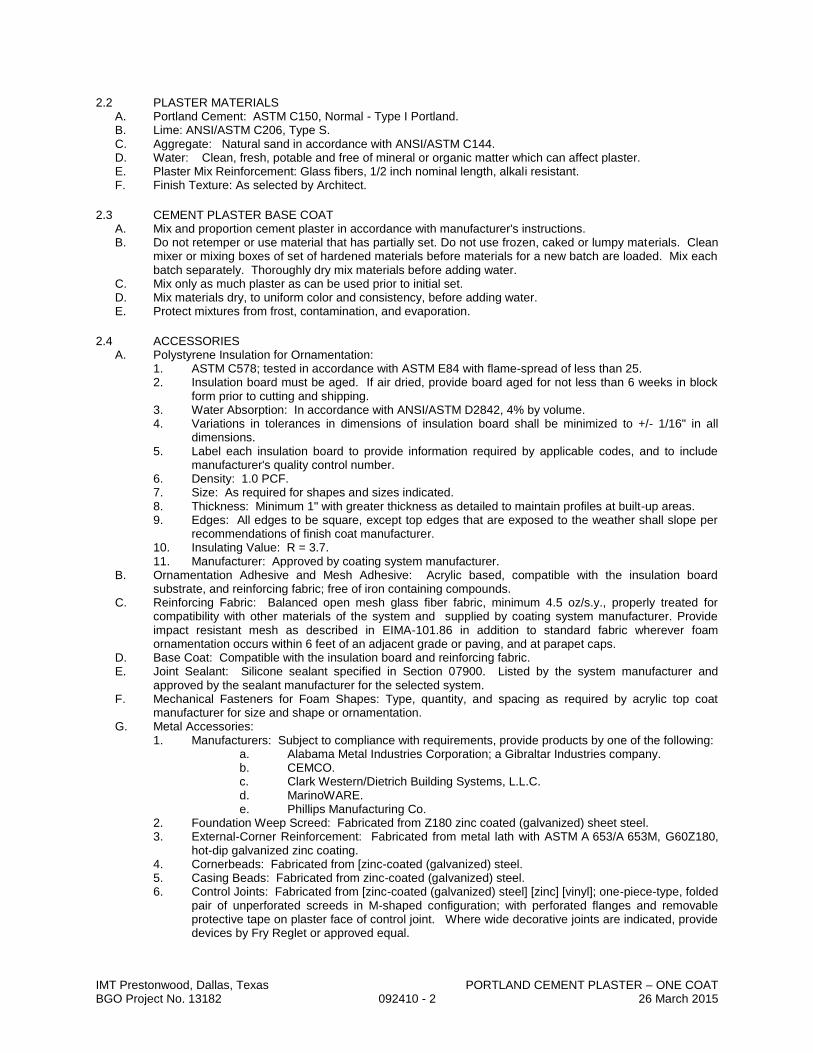
IMT Prestonwood, Dallas, Texas PORTLAND CEMENT PLASTER – ONE COAT BGO Project No. 13182 092410 - 2 26 March 2015
2.2 PLASTER MATERIALS A. Portland Cement: ASTM C150, Normal - Type I Portland. B. Lime: ANSI/ASTM C206, Type S. C. Aggregate: Natural sand in accordance with ANSI/ASTM C144. D. Water: Clean, fresh, potable and free of mineral or organic matter which can affect plaster. E. Plaster Mix Reinforcement: Glass fibers, 1/2 inch nominal length, alkali resistant. F. Finish Texture: As selected by Architect.
2.3 CEMENT PLASTER BASE COAT A. Mix and proportion cement plaster in accordance with manufacturer's instructions. B. Do not retemper or use material that has partially set. Do not use frozen, caked or lumpy materials. Clean
mixer or mixing boxes of set of hardened materials before materials for a new batch are loaded. Mix each batch separately. Thoroughly dry mix materials before adding water.
C. Mix only as much plaster as can be used prior to initial set. D. Mix materials dry, to uniform color and consistency, before adding water. E. Protect mixtures from frost, contamination, and evaporation.
2.4 ACCESSORIES A. Polystyrene Insulation for Ornamentation:
1. ASTM C578; tested in accordance with ASTM E84 with flame-spread of less than 25. 2. Insulation board must be aged. If air dried, provide board aged for not less than 6 weeks in block
form prior to cutting and shipping. 3. Water Absorption: In accordance with ANSI/ASTM D2842, 4% by volume. 4. Variations in tolerances in dimensions of insulation board shall be minimized to +/- 1/16" in all
dimensions. 5. Label each insulation board to provide information required by applicable codes, and to include
manufacturer's quality control number. 6. Density: 1.0 PCF. 7. Size: As required for shapes and sizes indicated. 8. Thickness: Minimum 1" with greater thickness as detailed to maintain profiles at built-up areas. 9. Edges: All edges to be square, except top edges that are exposed to the weather shall slope per
recommendations of finish coat manufacturer. 10. Insulating Value: R = 3.7. 11. Manufacturer: Approved by coating system manufacturer.
B. Ornamentation Adhesive and Mesh Adhesive: Acrylic based, compatible with the insulation board substrate, and reinforcing fabric; free of iron containing compounds.
C. Reinforcing Fabric: Balanced open mesh glass fiber fabric, minimum 4.5 oz/s.y., properly treated for compatibility with other materials of the system and supplied by coating system manufacturer. Provide impact resistant mesh as described in EIMA-101.86 in addition to standard fabric wherever foam ornamentation occurs within 6 feet of an adjacent grade or paving, and at parapet caps.
D. Base Coat: Compatible with the insulation board and reinforcing fabric. E. Joint Sealant: Silicone sealant specified in Section 07900. Listed by the system manufacturer and
approved by the sealant manufacturer for the selected system. F. Mechanical Fasteners for Foam Shapes: Type, quantity, and spacing as required by acrylic top coat
manufacturer for size and shape or ornamentation. G. Metal Accessories:
1. Manufacturers: Subject to compliance with requirements, provide products by one of the following: a. Alabama Metal Industries Corporation; a Gibraltar Industries company. b. CEMCO. c. Clark Western/Dietrich Building Systems, L.L.C. d. MarinoWARE. e. Phillips Manufacturing Co.
2. Foundation Weep Screed: Fabricated from Z180 zinc coated (galvanized) sheet steel. 3. External-Corner Reinforcement: Fabricated from metal lath with ASTM A 653/A 653M, G60Z180,
hot-dip galvanized zinc coating. 4. Cornerbeads: Fabricated from [zinc-coated (galvanized) steel. 5. Casing Beads: Fabricated from zinc-coated (galvanized) steel. 6. Control Joints: Fabricated from [zinc-coated (galvanized) steel] [zinc] [vinyl]; one-piece-type, folded
pair of unperforated screeds in M-shaped configuration; with perforated flanges and removable protective tape on plaster face of control joint. Where wide decorative joints are indicated, provide devices by Fry Reglet or approved equal.

IMT Prestonwood, Dallas, Texas PORTLAND CEMENT PLASTER – ONE COAT BGO Project No. 13182 092410 - 3 26 March 2015
7. Expansion Joints: Fabricated from zinc-coated (galvanized) steel; folded pair of unperforated screeds in M-shaped configuration; with expanded flanges.
2.5 FINISH COAT A. Premixed Exterior Finishing Coat: 100 percent acrylic copolymers, with integral color. B. Color: As selected by Architect or as indicated in Contract Documents. C. Acceptable Products:
1. TeifsFlex by Teifs Wall Systems. 2. Sto Flexfinish by StoCorp. 3. Parex DPR Acrylic Finish by ParexLaHabra.
PART 3 - EXECUTION
3.1 EXAMINATION A. Verify that surfaces and site conditions are ready to receive work. Verify that substrate workmanship is
within acceptable tolerances. B. Grounds and Blocking and Accessories: Verify items within walls, and other areas receiving plaster for
other Sections of work have been installed. C. Mechanical and Electrical: Verify services within walls have been tested and approved. D. Verify that furring, lathing and control/expansion joints are complete and tightly secured in place. E. Beginning of installation means acceptance of existing conditions.
3.2 PREPARATION A. Protect surfaces near the work of this Section from damage or disfiguration. B. Clean concrete surfaces of foreign matter. Clean surfaces using acid solutions, solvents, or detergents.
Wash surfaces with clean water.
3.3 APPLICATION - BASE COAT A. Apply plaster in accordance with manufacturer's instructions. B. Apply plaster by machine or hand. Interrupt plaster only at junctions of plaster planes, at openings or at
control joints. C. Layout do permit completion of an entire surface in one application. Maintain a wet edge. Work to corners
and joints, and do not allow material to set up within a distinct wall area. D. Interrupt plaster at control joints. Tool through to produce "V" joint at intersection of frames and other
items of metal or wood which act as plaster grounds. E. Nominal Plaster Thickness: As required by system manufacturer. F. Apply base coat with sufficient material and pressure to form keys on metal lath. G. Water Curing of Base Coat:
1. Follow procedures recommended by Portland Cement Association. 2. Cure minimum of 48 hours. 3. Prevent premature dry-out. 4. Allow base coat to cure a minimum of 6 days before applying elastomeric finish coat. 5. Upon completion, point-up plaster around trim and other locations where plaster meets dissimilar
materials. H. Cut out and patch defective or damaged plaster. I. Match patching of defective or damaged plaster to existing work in form and texture.

IMT Prestonwood, Dallas, Texas PORTLAND CEMENT PLASTER – ONE COAT BGO Project No. 13182 092410 - 4 26 March 2015
3.4 FOAM ORNAMENTATION INSTALLATION A. General: Install in accordance with system manufacturer's printed instructions. B. Adhere foam ornamentation to vertical surfaces in locations indicated C. Precut board as required to fit openings, projections, etc., stagger vertical joints and corners. D. Adhesive:
1. Apply mixed adhesive to the entire surface of the insulation board with a notched trowel in accordance with manufacturer's printed instructions.
2. Apply pressure over entire surface of board to ensure uniform contact and high initial grab. Abut joints tightly. Rasp flush irregularities in insulation board exceeding 1/16 inch.
E. Base Coat and Standard Reinforcing Fabric: 1. Using stainless steel trowel, apply base coat mixture to a uniform thickness of 1/16 inch. 2. Immediately place reinforcing fabric against the wet base coating, trowel from center to edges,
embedding fabric into the coating. 3. Use reinforcing fabric continuous at corners and lapped not less than 2-1/2 inches at fabric edges.
Provide an additional layer of reinforcing fabric at exterior corners. 4. Install additional reinforcing fabric at diagonally at corners of openings. 5. Avoid wrinkles while embedding the reinforcing fabric. 6. Back wrap insulation board at base. 7. Verify base coating surface is dry and hard before proceeding to finish application.
F. Base Coat and Reinforcing Mesh for Impact-Resistance Areas 1. Using stainless steel trowel, apply impact adhesive to entire surface of board to a uniform thickness
of 3/32 inch. 2. Immediately embed first layer of reinforcing mesh into wet base coat using trowel. Smooth until
mesh is fully embedded. Butt ends of mesh pieces tightly. Do not lap ends. 3. Allow 24 hours for base coat to form a positive bond. Protect from damage and weather while
curing. 4. Apply a second layer of standard reinforcing mesh and adhesive mixture over first layer of
reinforcing fabric as specified above.
3.5 ACRYLIC FINISH COAT INSTALLATION A. Using clean stainless steel trowel, apply a light coat of finish material directly to the cement plaster base
coat (or to the reinforced base coating over ornamentation areas). B. Apply and level during the same operation to the minimum attainable thickness consistent with uniform
coverage. C. Apply and texture finish continually over an entire surface. D. Work to corners or joints, and do not allow the material to set up within a distinct wall area. E. Furnish sufficient staging and workmen to accomplish a uniform appearance. F. Achieve final texture after veneer finish has jelled so that it does not stick to the trowel. G. Final Thickness: Not greater than the diameter of the largest aggregate of the finish material. H. Unless otherwise indicated, provide smooth sand finish.
3.6 TOLERANCES A. Maximum Variation from True Flatness: 1/8 inch in 10 feet as measured with a straight edge placed at any
location on the surface.
3.7 PATCHING A. Patch defects in workmanship and materials. Patches in finished areas shall match adjacent surfaces.
3.8 CLEANING A. Removing plaster and protective materials from expansion beads and metal accessories. Remove plaster
spatters and debris from other surfaces. Remove rubbish, debris, and scaffolds from spaces and leave broom clean.
3.9 FIELD QUALITY CONTROL A. Manufacturer's Field Services: Notify manufacturer prior to start of work and make arrangements for
manufacturer's technical representative to be present during first day's work to verify work is being conducted in accordance with their recommendations, and at minimum monthly intervals during the course of plastering work on the project. Report of site visit to be prepared on form attached, or similar form as approved by Owner.
END OF SECTION
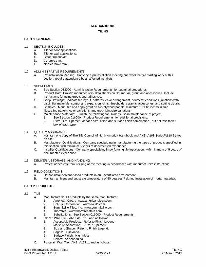
IMT Prestonwood, Dallas, Texas TILING BGO Project No. 13182 093000 - 1 26 March 2015
SECTION 093000
TILING
PART 1 GENERAL
1.1 SECTION INCLUDES A. Tile for floor applications. B. Tile for wall applications. C. Stone thresholds. D. Ceramic trim. E. Non-ceramic trim.
1.2 ADMINISTRATIVE REQUIREMENTS A. Preinstallation Meeting: Convene a preinstallation meeting one week before starting work of this
section; require attendance by all affected installers.
1.3 SUBMITTALS A. See Section 013000 - Administrative Requirements, for submittal procedures. B. Product Data: Provide manufacturers' data sheets on tile, mortar, grout, and accessories. Include
instructions for using grouts and adhesives. C. Shop Drawings: Indicate tile layout, patterns, color arrangement, perimeter conditions, junctions with
dissimilar materials, control and expansion joints, thresholds, ceramic accessories, and setting details. D. Samples: Mount tile and apply grout on two plywood panels, minimum 18 x 18 inches in size
illustrating pattern, color variations, and grout joint size variations. E. Maintenance Materials: Furnish the following for Owner's use in maintenance of project.
1. See Section 016000 - Product Requirements, for additional provisions. 2. Extra Tile: 1 percent of each size, color, and surface finish combination , but not less than 1
box of each type.
1.4 QUALITY ASSURANCE A. Maintain one copy of The Tile Council of North America Handbook and ANSI A108 Series/A118 Series
on site. B. Manufacturer Qualifications: Company specializing in manufacturing the types of products specified in
this section, with minimum 5 years of documented experience. C. Installer Qualifications: Company specializing in performing tile installation, with minimum of 5 years of
documented experience.
1.5 DELIVERY, STORAGE, AND HANDLING A. Protect adhesives from freezing or overheating in accordance with manufacturer's instructions.
1.6 FIELD CONDITIONS A. Do not install solvent-based products in an unventilated environment. B. Maintain ambient and substrate temperature of 50 degrees F during installation of mortar materials.
PART 2 PRODUCTS
2.1 TILE A. Manufacturers: All products by the same manufacturer.
1. American Olean: www.americanolean.com. 2. Dal-Tile Corporation: www.daltile.com. 3. Summitville Tiles, Inc: www.summitville.com. 4. Thorntree: www.thorntreestate.com. 5. Substitutions: See Section 016000 - Product Requirements.
B. Glazed Wall Tile : ANSI A137.1 , and as follows: 1. Acceptable Products: Refer to Finish Legend. 2. Moisture Absorption: 3.0 to 7.0 percent. 3. Size and Shape: Refer to Finish Legend. 4. Edges: Cushioned. 5. Surface Finish: High gloss. 6. Colors: As scheduled.
C. Porcelain Wall Tile: ANSI A137.1, and as follows:

IMT Prestonwood, Dallas, Texas TILING BGO Project No. 13182 093000 - 2 26 March 2015
1. Acceptable Products: Refer to Finish Legend. 2. Moisture Absorption: 0 to 0.5 percent. 3. Face: Plain. 4. Edges: Cushioned. 5. Size and Shape: Refer to Finish Legend. 6. Colors and Surface Finish: As scheduled.
D. Porcelain Floor Tile: ANSI A137.1, and as follows: 1. Acceptable Products: Refer to Finish Legend. 2. Moisture Absorption: 0 to 0.5 percent. 3. Face: Plain. 4. Edges: Cushioned. 5. Thickness: 3/8 inch. 6. Size and Shape: Refer to Finish Legend. 7. Colors and Surface Finish: As scheduled.
2.2 TRIM AND ACCESSORIES A. Ceramic Trim: Matching bullnose, double bullnose, cove base, and cove ceramic shapes in sizes
coordinated with field tile. 1. Applications: Use in the following locations:
a. Open Edges: Bullnose. b. Inside Corners: Jointed. c. Floor to Wall Joints: Cove base.
2. Manufacturer: Same as for tile. B. Non-Ceramic Trim: Satin brass anodized extruded aluminum, style and dimensions to suit application,
for setting using tile mortar or adhesive. 1. Manufacturer:
a. Schluter-Systems: www.schluter.com. b. Genesis APS International: www.genesis-aps.com.
C. Thresholds: Marble, white or gray, honed finish; 2 inches wide by full width of wall or frame opening; 1/2 inch thick; beveled one long edge with radiused corners on top side; without holes, cracks, or open seams. 1. Applications: Provide at the following locations:
a. At doorways where tile terminates.
2.3 SETTING MATERIALS A. Latex-Portland Cement Mortar Bond Coat: ANSI A118.4.
1. Application(s): Use this type of bond coat where indicated and where no other type of bond coat is indicated.
2. Products: a. Custom Building Products; MegaLite: www.custombuildingproducts.com. b. LATICRETE International, Inc ; LATICRETE 254 Platinum: www.laticrete.com. c. ProSpec, an Oldcastle brand ; Permalastic System: www.prospec.com. d. Substitutions: See Section 016000 - Product Requirements.
2.4 GROUTS A. Manufacturers:
1. Custom Building Products: www.custombuildingproducts.com. 2. LATICRETE International, Inc: www.laticrete.com. 3. MAPEI Corporation: www.mapei.com. 4. Substitutions: See Section 016000 - Product Requirements.
B. Standard Grout: ANSI A118.6 standard cement grout. 1. Applications: Use this type of grout where indicated and where no other type of grout is
indicated. 2. Use sanded grout for joints 1/8 inch wide and larger; use unsanded grout for joints less than 1/8
inch wide. 3. Color(s): As scheduled.
2.5 THICK-BED MATERIALS (for use at tiled showers) A. Mortar Bed Materials: Portland cement, sand , latex additive, and water.
1. Products: a. LATICRETE International, Inc ; LATICRETE 3701 Fortified Mortar Bed:
www.laticrete.com.
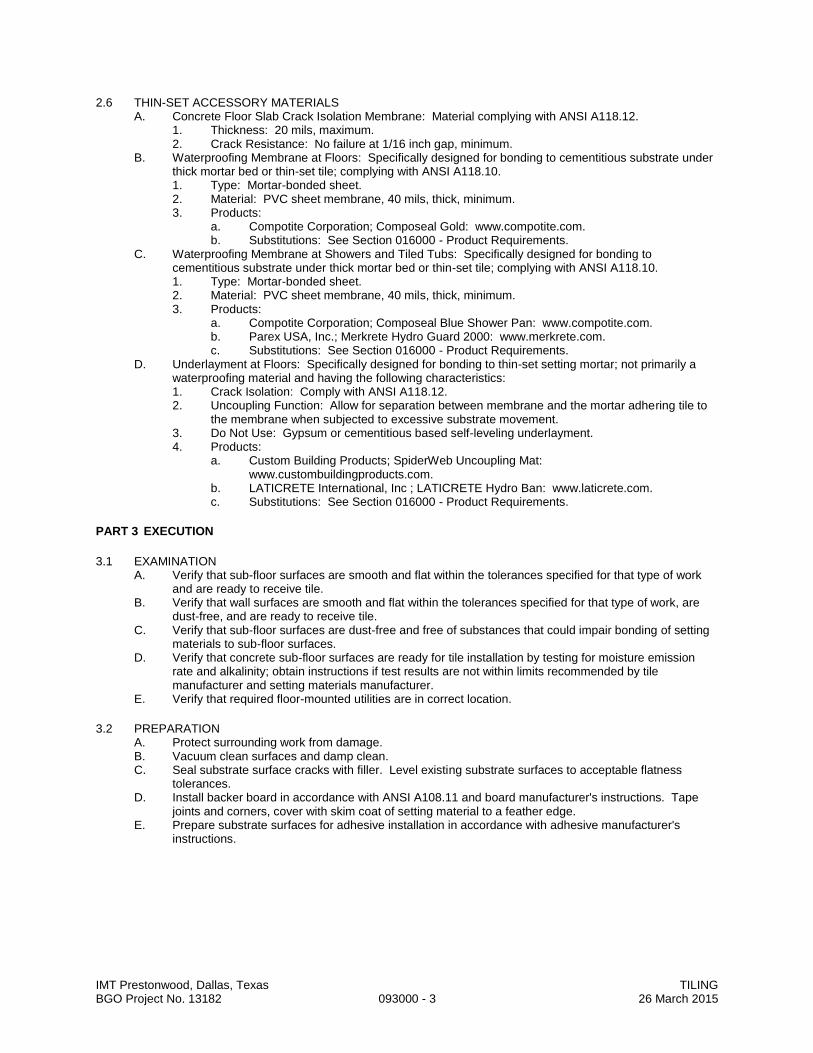
IMT Prestonwood, Dallas, Texas TILING BGO Project No. 13182 093000 - 3 26 March 2015
2.6 THIN-SET ACCESSORY MATERIALS A. Concrete Floor Slab Crack Isolation Membrane: Material complying with ANSI A118.12.
1. Thickness: 20 mils, maximum. 2. Crack Resistance: No failure at 1/16 inch gap, minimum.
B. Waterproofing Membrane at Floors: Specifically designed for bonding to cementitious substrate under thick mortar bed or thin-set tile; complying with ANSI A118.10. 1. Type: Mortar-bonded sheet. 2. Material: PVC sheet membrane, 40 mils, thick, minimum. 3. Products:
a. Compotite Corporation; Composeal Gold: www.compotite.com. b. Substitutions: See Section 016000 - Product Requirements.
C. Waterproofing Membrane at Showers and Tiled Tubs: Specifically designed for bonding to cementitious substrate under thick mortar bed or thin-set tile; complying with ANSI A118.10. 1. Type: Mortar-bonded sheet. 2. Material: PVC sheet membrane, 40 mils, thick, minimum. 3. Products:
a. Compotite Corporation; Composeal Blue Shower Pan: www.compotite.com. b. Parex USA, Inc.; Merkrete Hydro Guard 2000: www.merkrete.com. c. Substitutions: See Section 016000 - Product Requirements.
D. Underlayment at Floors: Specifically designed for bonding to thin-set setting mortar; not primarily a waterproofing material and having the following characteristics: 1. Crack Isolation: Comply with ANSI A118.12. 2. Uncoupling Function: Allow for separation between membrane and the mortar adhering tile to
the membrane when subjected to excessive substrate movement. 3. Do Not Use: Gypsum or cementitious based self-leveling underlayment. 4. Products:
a. Custom Building Products; SpiderWeb Uncoupling Mat: www.custombuildingproducts.com.
b. LATICRETE International, Inc ; LATICRETE Hydro Ban: www.laticrete.com. c. Substitutions: See Section 016000 - Product Requirements.
PART 3 EXECUTION
3.1 EXAMINATION A. Verify that sub-floor surfaces are smooth and flat within the tolerances specified for that type of work
and are ready to receive tile. B. Verify that wall surfaces are smooth and flat within the tolerances specified for that type of work, are
dust-free, and are ready to receive tile. C. Verify that sub-floor surfaces are dust-free and free of substances that could impair bonding of setting
materials to sub-floor surfaces. D. Verify that concrete sub-floor surfaces are ready for tile installation by testing for moisture emission
rate and alkalinity; obtain instructions if test results are not within limits recommended by tile manufacturer and setting materials manufacturer.
E. Verify that required floor-mounted utilities are in correct location.
3.2 PREPARATION A. Protect surrounding work from damage. B. Vacuum clean surfaces and damp clean. C. Seal substrate surface cracks with filler. Level existing substrate surfaces to acceptable flatness
tolerances. D. Install backer board in accordance with ANSI A108.11 and board manufacturer's instructions. Tape
joints and corners, cover with skim coat of setting material to a feather edge. E. Prepare substrate surfaces for adhesive installation in accordance with adhesive manufacturer's
instructions.
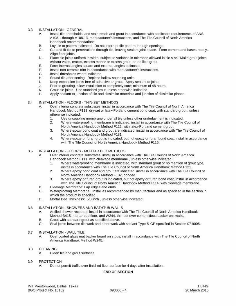
IMT Prestonwood, Dallas, Texas TILING BGO Project No. 13182 093000 - 4 26 March 2015
3.3 INSTALLATION - GENERAL A. Install tile, thresholds, and stair treads and grout in accordance with applicable requirements of ANSI
A108.1 through A108.13, manufacturer's instructions, and The Tile Council of North America Handbook recommendations.
B. Lay tile to pattern indicated. Do not interrupt tile pattern through openings. C. Cut and fit tile to penetrations through tile, leaving sealant joint space. Form corners and bases neatly.
Align floor joints. D. Place tile joints uniform in width, subject to variance in tolerance allowed in tile size. Make grout joints
without voids, cracks, excess mortar or excess grout, or too little grout. E. Form internal angles square and external angles bullnosed. F. Install non-ceramic trim in accordance with manufacturer's instructions. G. Install thresholds where indicated. H. Sound tile after setting. Replace hollow sounding units. I. Keep expansion joints free of adhesive or grout. Apply sealant to joints. J. Prior to grouting, allow installation to completely cure; minimum of 48 hours. K. Grout tile joints. Use standard grout unless otherwise indicated. L. Apply sealant to junction of tile and dissimilar materials and junction of dissimilar planes.
3.4 INSTALLATION - FLOORS - THIN-SET METHODS A. Over interior concrete substrates, install in accordance with The Tile Council of North America
Handbook Method F113, dry-set or latex-Portland cement bond coat, with standard grout , unless otherwise indicated. 1. Use uncoupling membrane under all tile unless other underlayment is indicated. 2. Where waterproofing membrane is indicated, install in accordance with The Tile Council of
North America Handbook Method F122, with latex-Portland cement grout. 3. Where epoxy bond coat and grout are indicated, install in accordance with The Tile Council of
North America Handbook Method F131. 4. Where epoxy or furan grout is indicated, but not epoxy or furan bond coat, install in accordance
with The Tile Council of North America Handbook Method F115.
3.5 INSTALLATION - FLOORS - MORTAR BED METHODS A. Over interior concrete substrates, install in accordance with The Tile Council of North America
Handbook Method F111, with cleavage membrane , unless otherwise indicated. 1. Where waterproofing membrane is indicated, with standard grout or no mention of grout type,
install in accordance with The Tile Council of North America Handbook Method F121. 2. Where epoxy bond coat and grout are indicated, install in accordance with The Tile Council of
North America Handbook Method F132, bonded. 3. Where epoxy or furan grout is indicated, but not epoxy or furan bond coat, install in accordance
with The Tile Council of North America Handbook Method F114, with cleavage membrane. B. Cleavage Membrane: Lap edges and ends. C. Waterproofing Membrane: Install as recommended by manufacturer and as specified in the section in
which the product is specified. D. Mortar Bed Thickness: 5/8 inch , unless otherwise indicated.
3.6 INSTALLATION - SHOWERS AND BATHTUB WALLS A. At tiled shower receptors install in accordance with The Tile Council of North America Handbook
Method B415, mortar bed floor, and W244, thin-set over cementitious backer unit walls. B. Grout with standard grout as specified above. C. Seal joints between tile work and other work with sealant Type S-GP specified in Section 07 9005.
3.7 INSTALLATION - WALL TILE A. Over coated glass mat backer board on studs, install in accordance with The Tile Council of North
America Handbook Method W245.
3.8 CLEANING A. Clean tile and grout surfaces.
3.9 PROTECTION A. Do not permit traffic over finished floor surface for 4 days after installation.
END OF SECTION

IMT Prestonwood, Dallas, Texas RUBBER TILE FLOORING BGO Project No. 13182 096240 - 1 26 March 2015
SECTION 096240
RUBBER TILE FLOORING
PART 1 - GENERAL
1.1 SUMMARY A. Related Documents: General and Supplementary Conditions of the Contract, Division 01 - General
Requirements, and Drawings are applicable to this Section. B. Section Includes:
1. Rubber tile flooring, suitable and appropriate for use at fitness room, slip resistant, interchangeable parts.
1.2 QUALITY ASSURANCE A. Manufacturer Qualifications:
1. All products covered under this Section shall be produced by a single manufacturer unless otherwise specified.
2. Manufacturer shall submit evidence of having not less 10 years successful production of this product.
1.3 SUBMITTALS A. Submit in exact accordance with Section 013000. B. Shop Drawings and Product Data:
1. Submit fabrication details and erection drawings. 2. Submit manufacturer's specifications to evidence compliance with these specifications. 3. Manufacturer's Product Data shall be clearly and specifically marked to indicate the specific models
or types intended for submittal and desired approval. 4. Product Data which is unmarked or unclear as to exact intended submittal will be returned not
reviewed to submitter. C. Samples: Submit full size samples of each shape, size and color specified or required.
1.4 DELIVERY, STORAGE AND HANDLING A. Refer to Section 016000. B. Deliver, store and handle products in exact accordance with the manufacturer's latest published
requirements and specifications.
PART 2 - PRODUCTS
2.1 ACCEPTABLE MANUFACTURERS A. Manufacturers: Subject to compliance with requirements, provide products by one of the following:.
1. Action Floor Systems, LLC. 2. Amarco Products. 3. American Floor Products Company, Inc. 4. ECORE International. 5. Flexco. 6. Horner Flooring Company, Inc. 7. Johnsonite; a Tarkett company. 8. Mondo America Inc. 9. Musson Rubber Co. 10. Pawling Corporation; Architectural Products Division.
2.2 MATERIALS A. Tiles shall be made of molded top quality recycled rubber with matte finish. B. Size: 24 x 24 inch x 10 mm thickness. C. Color/pattern: Refer to Finish Legend.
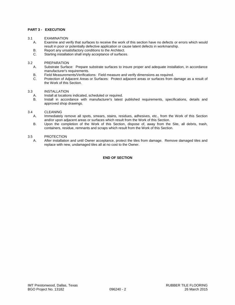
IMT Prestonwood, Dallas, Texas RUBBER TILE FLOORING BGO Project No. 13182 096240 - 2 26 March 2015
PART 3 - EXECUTION
3.1 EXAMINATION A. Examine and verify that surfaces to receive the work of this section have no defects or errors which would
result in poor or potentially defective application or cause latent defects in workmanship. B. Report any unsatisfactory conditions to the Architect. C. Starting installation shall imply acceptance of surfaces.
3.2 PREPARATION A. Substrate Surface: Prepare substrate surfaces to insure proper and adequate installation, in accordance
manufacturer's requirements. B. Field Measurements/Verifications: Field measure and verify dimensions as required. C. Protection of Adjacent Areas or Surfaces: Protect adjacent areas or surfaces from damage as a result of
the Work of this Section.
3.3 INSTALLATION A. Install at locations indicated, scheduled or required. B. Install in accordance with manufacturer's latest published requirements, specifications, details and
approved shop drawings.
3.4 CLEANING A. Immediately remove all spots, smears, stains, residues, adhesives, etc., from the Work of this Section
and/or upon adjacent areas or surfaces which result from the Work of this Section. B. Upon the completion of the Work of this Section, dispose of, away from the Site, all debris, trash,
containers, residue, remnants and scraps which result from the Work of this Section.
3.5 PROTECTION A. After installation and until Owner acceptance, protect the tiles from damage. Remove damaged tiles and
replace with new, undamaged tiles all at no cost to the Owner.
END OF SECTION

IMT Prestonwood, Dallas, Texas WOOD STRIP FLOORING BGO Project No. 13182 096429 - 1 26 March 2015
SECTION 096429
WOOD STRIP FLOORING
PART 1 - GENERAL
1.1 SUMMARY A. This Section includes the following:
1. Engineered wood strip flooring.
1.2 SUBMITTALS A. Product Data: For each type of product indicated. B. Shop Drawings: Show installation details including location and layout of each type of wood flooring and
accessory. C. Samples for Verification: For each type of wood flooring and accessory, with stain color and finish
required, approximately 12 inches(300 mm) long and of same thickness and material indicated for the Work. Include sample sets showing the full range of normal color and texture variations expected.
1.3 QUALITY ASSURANCE A. Installer Qualifications: An experienced installer who has completed wood flooring similar in material,
design, and extent to that indicated for this Project and whose work has resulted in wood flooring installations with a record of successful in-service performance.
B. Source Limitations: Obtain each type of material and product from one source with resources to provide materials and products of consistent quality in appearance and physical properties.
C. Hardwood Flooring: Comply with NOFMA grading rules for species, grade, and cut. 1. Certification: Provide flooring that carries NOFMA grade stamp on each bundle or piece.
1.4 DELIVERY, STORAGE, AND HANDLING A. Deliver wood flooring materials in unopened cartons or bundles. B. Protect wood flooring from exposure to moisture. Do not deliver wood flooring until after concrete,
masonry, plaster, ceramic tile, and similar wet-work is complete and dry. C. Store wood flooring materials in a dry, warm, well-ventilated, weathertight location. D. Move wood flooring into spaces where it will be installed, at least seven days before installation.
1.5 PROJECT CONDITIONS A. Conditioning: Maintain relative humidity planned for building occupants and an ambient temperature
between 65 and 75 deg F(18 and 24 deg C) in spaces to receive wood flooring for at least seven days before installation, during installation, and for at least seven days after installation. After post-installation period, maintain relative humidity and ambient temperature planned for building occupants. 1. Do not install flooring until it adjusts to the relative humidity of and is at the same temperature as
the space where it is to be installed. 2. Close spaces to traffic during flooring installation and for time period after installation
recommended in writing by flooring and finish manufacturers. B. Install factory-finished wood flooring after other finishing operations, including painting, have been
completed.
1.6 EXTRA MATERIALS A. Furnish extra materials described below, before installation begins, that match products installed and that
are packaged with protective covering for storage and identified with labels describing contents. 1. Wood Flooring: Equal to 1 percent of amount installed for each type and finish indicated.
PART 2 - PRODUCTS
2.1 MANUFACTURERS A. Products: Subject to compliance with requirements, provide one of the products indicated for each
designation in the Wood Flooring Schedule at the end of Part 3.

IMT Prestonwood, Dallas, Texas WOOD STRIP FLOORING BGO Project No. 13182 096429 - 2 26 March 2015
2.2 SOLID-WOOD STRIP AND PLANK FLOORING A. Strip and Plank Flooring: Provide kiln-dried wood flooring as follows:
1. Species, Grade, and Cut: Refer to Finish Legend. 2. Thickness: Manufacturer’s standard of either 3/8 or ½ inch. 3. Face Width: Refer to Finish Legend. 4. Matching: Tongue and groove, and end matched. 5. Construction: Three or five ply, depending on thickness. 6. Length: Manufacturer's standard. 7. Edges: As indicated by product designation above. 8. Finish: Manufacturer's standard UV urethane in color selected by Architect from full range. 9. Acceptable Product: Refer to Finish Legend.
2.3 ACCESSORY MATERIALS A. Wood Flooring Adhesive: Mastic recommended by flooring and adhesive manufacturers for application
indicated.
PART 3 - EXECUTION
3.1 EXAMINATION A. Examine substrates, areas, and conditions, with Installer present, for compliance with requirements,
installation tolerances, and other conditions affecting performance of wood flooring. Proceed with installation only after unsatisfactory conditions have been corrected.
B. Concrete Slabs: Verify that concrete slabs comply with requirements specified Division 3 Section "Cast-in-Place Concrete." 1. Verify that slabs are dry according to test methods recommended by flooring manufacturer or, if
none, by test methods in NOFMA's "Installing Hardwood Flooring." 2. Where wood flooring is installed directly over concrete slabs, grind high spots and fill low spots to
provide a maximum 1/4-inch(6-mm) deviation in any direction when checked with a 10-foot(3-m) straight edge.
3. Where wood flooring is adhesively attached to concrete slabs, verify that slabs are free of curing compounds, sealers, hardeners, and other materials that may interfere with adhesive bond.
3.2 INSTALLATION A. General: Comply with flooring manufacturer's written instructions, but not less than recommendations in
NOFMA's "Installing Hardwood Flooring," as applicable to flooring type. B. Install sound isolation sheeting in accordance with manufacturer’s instructions. C. Pattern: Lay wood flooring in pattern indicated on Drawings or, if not indicated, as directed by Architect. D. Engineered-Wood Flooring: Set in adhesive according to manufacturer's written instructions.
3.3 PROTECTION A. Cover installed wood flooring to protect it from damage or deterioration, before and after finishing, during
remainder of construction period. Use heavy kraft-paper or other suitable covering. Do not use plastic sheet or film that could cause condensation. 1. Do not cover site-finished floors with kraft paper, or any other material, until finish reaches full cure,
but not less than seven days after applying last coat.
END OF SECTION

IMT Prestonwood, Dallas, Texas RESILIENT FLOORING BGO Project No. 13182 096500 - 1 26 March 2015
SECTION 096500
RESILIENT FLOORING
PART 1 GENERAL
1.1 SECTION INCLUDES A. Resilient flooring. B. Resilient base. C. Installation accessories.
1.2 SUBMITTALS A. See Section 013000 - Administrative Requirements, for submittal procedures. B. Product Data: Provide data on specified products, describing physical and performance
characteristics; including sizes, patterns and colors available; and installation instructions. C. Selection Samples: Submit manufacturer's complete set of color samples for Architect's initial
selection. D. Certification: Prior to installation of flooring, submit written certification by flooring manufacturer and
adhesive manufacturer that condition of sub-floor is acceptable. E. Maintenance Data: Include maintenance procedures, recommended maintenance materials, and
suggested schedule for cleaning, stripping, and re-waxing.
1.3 DELIVERY, STORAGE, AND HANDLING A. Protect roll materials from damage by storing on end.
1.4 FIELD CONDITIONS A. Maintain temperature in storage area between 55 degrees F and 90 degrees F. B. Store materials for not less than 48 hours prior to installation in area of installation at a temperature of
70 degrees F to achieve temperature stability. Thereafter, maintain conditions above 55 degrees F.
PART 2 PRODUCTS
2.1 FLOORING MATERIALS A. Vinyl Composition Tile
1. FS SS-T-312, Type IV, Composition 1. 2. Size: 12 by 12 inches, 1/8 inch thick. 3. Acceptable Product: Refer to Finish Legend.
B. Vinyl Plank Flooring: Meeting ASTM F 1700. 1. Class: As indicated by product designations. 2. Type: Type B, embossed surface. 3. Thickness: 0.080 inch minimum. 4. Size: 3 by 36 inches. 5. Acceptable Manufacturers and Product: Refer to Finish Legend.
2.2 RESILIENT BASE A. Resilient Base: ASTM F1861, Type TS rubber, vulcanized thermoset; top set Style B, Cove, and as
follows: 1. Height: As scheduled. 2. Thickness: 0.125 inch thick. 3. Finish: Satin. 4. Length: Roll. 5. Color: Color as selected from manufacturer's standards. 6. Accessories: Premolded external corners and end stops. 7. Manufacturers:
a. Burke Flooring: www.burkemercer.com. b. Johnsonite, Inc: www.johnsonite.com. c. Roppe Corp: www.roppe.com. d. Substitutions: See Section 016000 - Product Requirements.
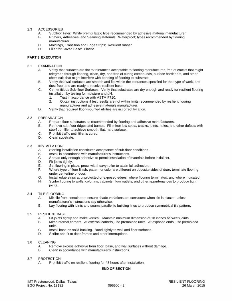
IMT Prestonwood, Dallas, Texas RESILIENT FLOORING BGO Project No. 13182 096500 - 2 26 March 2015
2.3 ACCESSORIES A. Subfloor Filler: White premix latex; type recommended by adhesive material manufacturer. B. Primers, Adhesives, and Seaming Materials: Waterproof; types recommended by flooring
manufacturer. C. Moldings, Transition and Edge Strips: Resilient rubber. D. Filler for Coved Base: Plastic.
PART 3 EXECUTION
3.1 EXAMINATION A. Verify that surfaces are flat to tolerances acceptable to flooring manufacturer, free of cracks that might
telegraph through flooring, clean, dry, and free of curing compounds, surface hardeners, and other chemicals that might interfere with bonding of flooring to substrate.
B. Verify that wall surfaces are smooth and flat within the tolerances specified for that type of work, are dust-free, and are ready to receive resilient base.
C. Cementitious Sub-floor Surfaces: Verify that substrates are dry enough and ready for resilient flooring installation by testing for moisture and pH. 1. Test in accordance with ASTM F710. 2. Obtain instructions if test results are not within limits recommended by resilient flooring
manufacturer and adhesive materials manufacturer. D. Verify that required floor-mounted utilities are in correct location.
3.2 PREPARATION A. Prepare floor substrates as recommended by flooring and adhesive manufacturers. B. Remove sub-floor ridges and bumps. Fill minor low spots, cracks, joints, holes, and other defects with
sub-floor filler to achieve smooth, flat, hard surface. C. Prohibit traffic until filler is cured. D. Clean substrate.
3.3 INSTALLATION A. Starting installation constitutes acceptance of sub-floor conditions. B. Install in accordance with manufacturer's instructions. C. Spread only enough adhesive to permit installation of materials before initial set. D. Fit joints tightly. E. Set flooring in place, press with heavy roller to attain full adhesion. F. Where type of floor finish, pattern or color are different on opposite sides of door, terminate flooring
under centerline of door. G. Install edge strips at unprotected or exposed edges, where flooring terminates, and where indicated. H. Scribe flooring to walls, columns, cabinets, floor outlets, and other appurtenances to produce tight
joints.
3.4 TILE FLOORING A. Mix tile from container to ensure shade variations are consistent when tile is placed, unless
manufacturer's instructions say otherwise. B. Lay flooring with joints and seams parallel to building lines to produce symmetrical tile pattern.
3.5 RESILIENT BASE A. Fit joints tightly and make vertical. Maintain minimum dimension of 18 inches between joints. B. Miter internal corners. At external corners, use premolded units. At exposed ends, use premolded
units. C. Install base on solid backing. Bond tightly to wall and floor surfaces. D. Scribe and fit to door frames and other interruptions.
3.6 CLEANING A. Remove excess adhesive from floor, base, and wall surfaces without damage. B. Clean in accordance with manufacturer's instructions.
3.7 PROTECTION A. Prohibit traffic on resilient flooring for 48 hours after installation.
END OF SECTION

IMT Prestonwood, Dallas, Texas CARPETING BGO Project No. 13182 096800 - 1 26 March 2015
SECTION 096800
CARPETING
PART 1 GENERAL
1.1 SECTION INCLUDES A. Carpet, stretched-in, with cushion underlay. B. Accessories.
1.2 SUBMITTALS A. See Section 013000 - Administrative Requirements, for submittal procedures. B. Shop Drawings: Indicate seaming plan, method of joining seams, direction of carpet pile and pattern,
location of edge moldings and edge bindings. C. Product Data: Provide data on specified products, describing physical and performance
characteristics; sizes, patterns, colors available, and method of installation. D. Samples: Submit two samples in size illustrating color and pattern for each carpet material specified. E. Maintenance Data: Include maintenance procedures, recommended maintenance materials, and
suggested schedule for cleaning. F. Sustainable Submittals:
1. Product data for adhesives, including printed statement of VOC content. 2. Product data for carpet to comply with CRI Green Label program
1.3 QUALITY ASSURANCE A. Manufacturer Qualifications: Company specializing in manufacturing specified carpet with minimum
three years documented experience. B. Installer Qualifications: Company specializing in installing carpet with minimum three years
experience.
1.4 FIELD CONDITIONS A. Store materials in area of installation for minimum period of 24 hours prior to installation. B. Maintain minimum 70 degrees F ambient temperature 24 hours prior to, during and 24 hours after
installation. C. Ventilate installation area during installation and for 72 hours after installation.
PART 2 PRODUCTS
2.1 CARPET A. Carpet:
1. Acceptable Products: Refer to Finish Legend. 2. Products must meet CRI Green Label and Green Label Plus requirements.
2.2 CUSHION A. Cushion Underlay: FS- LC-1369; 72 inches wide rolls; re-bonded polyurethane foam; particle size not
to exceed 1/2 inch; density of 6.0 pcf plus or minus 5 percent; thickness of 1/2 inch plus or minus 1/32 inch;
2.3 ACCESSORIES A. Sub-Floor Filler: Type recommended by carpet manufacturer. B. Tackless Strip: Carpet gripper, of type recommended by carpet manufacturer to suit application, with
attachment devices. C. Moldings and Edge Strips: Resilient rubber; refer to Section 096500. D. Seam Adhesive: Recommended by manufacturer. E. Contact Adhesive: Compatible with carpet material.
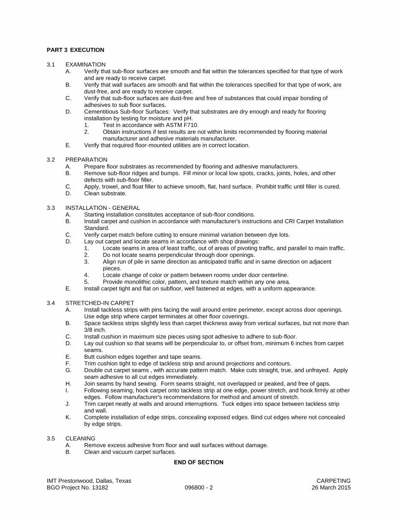
IMT Prestonwood, Dallas, Texas CARPETING BGO Project No. 13182 096800 - 2 26 March 2015
PART 3 EXECUTION
3.1 EXAMINATION A. Verify that sub-floor surfaces are smooth and flat within the tolerances specified for that type of work
and are ready to receive carpet. B. Verify that wall surfaces are smooth and flat within the tolerances specified for that type of work, are
dust-free, and are ready to receive carpet. C. Verify that sub-floor surfaces are dust-free and free of substances that could impair bonding of
adhesives to sub floor surfaces. D. Cementitious Sub-floor Surfaces: Verify that substrates are dry enough and ready for flooring
installation by testing for moisture and pH. 1. Test in accordance with ASTM F710. 2. Obtain instructions if test results are not within limits recommended by flooring material
manufacturer and adhesive materials manufacturer. E. Verify that required floor-mounted utilities are in correct location.
3.2 PREPARATION A. Prepare floor substrates as recommended by flooring and adhesive manufacturers. B. Remove sub-floor ridges and bumps. Fill minor or local low spots, cracks, joints, holes, and other
defects with sub-floor filler. C. Apply, trowel, and float filler to achieve smooth, flat, hard surface. Prohibit traffic until filler is cured. D. Clean substrate.
3.3 INSTALLATION - GENERAL A. Starting installation constitutes acceptance of sub-floor conditions. B. Install carpet and cushion in accordance with manufacturer's instructions and CRI Carpet Installation
Standard. C. Verify carpet match before cutting to ensure minimal variation between dye lots. D. Lay out carpet and locate seams in accordance with shop drawings:
1. Locate seams in area of least traffic, out of areas of pivoting traffic, and parallel to main traffic. 2. Do not locate seams perpendicular through door openings. 3. Align run of pile in same direction as anticipated traffic and in same direction on adjacent
pieces. 4. Locate change of color or pattern between rooms under door centerline. 5. Provide monolithic color, pattern, and texture match within any one area.
E. Install carpet tight and flat on subfloor, well fastened at edges, with a uniform appearance.
3.4 STRETCHED-IN CARPET A. Install tackless strips with pins facing the wall around entire perimeter, except across door openings.
Use edge strip where carpet terminates at other floor coverings. B. Space tackless strips slightly less than carpet thickness away from vertical surfaces, but not more than
3/8 inch. C. Install cushion in maximum size pieces using spot adhesive to adhere to sub-floor. D. Lay out cushion so that seams will be perpendicular to, or offset from, minimum 6 inches from carpet
seams. E. Butt cushion edges together and tape seams. F. Trim cushion tight to edge of tackless strip and around projections and contours. G. Double cut carpet seams , with accurate pattern match. Make cuts straight, true, and unfrayed. Apply
seam adhesive to all cut edges immediately. H. Join seams by hand sewing. Form seams straight, not overlapped or peaked, and free of gaps. I. Following seaming, hook carpet onto tackless strip at one edge, power stretch, and hook firmly at other
edges. Follow manufacturer's recommendations for method and amount of stretch. J. Trim carpet neatly at walls and around interruptions. Tuck edges into space between tackless strip
and wall. K. Complete installation of edge strips, concealing exposed edges. Bind cut edges where not concealed
by edge strips.
3.5 CLEANING A. Remove excess adhesive from floor and wall surfaces without damage. B. Clean and vacuum carpet surfaces.
END OF SECTION
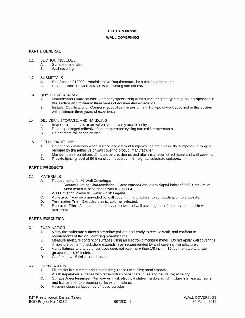
IMT Prestonwood, Dallas, Texas WALL COVERINGS BGO Project No. 13182 097200 - 1 26 March 2015
SECTION 097200
WALL COVERINGS
PART 1 GENERAL
1.1 SECTION INCLUDES A. Surface preparation. B. Wall covering.
1.2 SUBMITTALS A. See Section 013000 - Administrative Requirements, for submittal procedures. B. Product Data: Provide data on wall covering and adhesive.
1.3 QUALITY ASSURANCE A. Manufacturer Qualifications: Company specializing in manufacturing the type of products specified in
this section with minimum three years of documented experience. B. Installer Qualifications: Company specializing in performing the type of work specified in this section
with minimum three years of experience.
1.4 DELIVERY, STORAGE, AND HANDLING A. Inspect roll materials at arrival on site, to verify acceptability. B. Protect packaged adhesive from temperature cycling and cold temperatures. C. Do not store roll goods on end.
1.5 FIELD CONDITIONS A. Do not apply materials when surface and ambient temperatures are outside the temperature ranges
required by the adhesive or wall covering product manufacturer. B. Maintain these conditions 24 hours before, during, and after installation of adhesive and wall covering. C. Provide lighting level of 80 ft candles measured mid-height at substrate surfaces.
PART 2 PRODUCTS
2.1 MATERIALS A. Requirements for All Wall Coverings:
1. Surface Burning Characteristics: Flame spread/Smoke developed index of 25/50, maximum, when tested in accordance with ASTM E84.
B. Wall Covering Products: Refer Finish Legend. C. Adhesive: Type recommended by wall covering manufacturer to suit application to substrate. D. Termination Trim: Extruded plastic, color as selected. E. Substrate Filler: As recommended by adhesive and wall covering manufacturers; compatible with
substrate.
PART 3 EXECUTION
3.1 EXAMINATION A. Verify that substrate surfaces are prime painted and ready to receive work, and conform to
requirements of the wall covering manufacturer. B. Measure moisture content of surfaces using an electronic moisture meter. Do not apply wall coverings
if moisture content of substrate exceeds level recommended by wall covering manufacturer. C. Verify flatness tolerance of surfaces does not vary more than 1/8 inch in 10 feet nor vary at a rate
greater than 1/16 inch/ft. D. Confirm Level 5 finish on substrate.
3.2 PREPARATION A. Fill cracks in substrate and smooth irregularities with filler; sand smooth. B. Wash impervious surfaces with tetra-sodium phosphate, rinse and neutralize; wipe dry. C. Surface Appurtenances: Remove or mask electrical plates, hardware, light fixture trim, escutcheons,
and fittings prior to preparing surfaces or finishing. D. Vacuum clean surfaces free of loose particles.

IMT Prestonwood, Dallas, Texas WALL COVERINGS BGO Project No. 13182 097200 - 2 26 March 2015
3.3 INSTALLATION A. Apply adhesive and wall covering in accordance with manufacturer's instructions. B. Razor trim edges on flat work table. Do not razor cut on gypsum board surfaces. C. Apply wall covering smooth, without wrinkles, gaps or overlaps. Eliminate air pockets and ensure full
bond to substrate surface. Butt edges tightly. D. Horizontal seams are not acceptable. E. Do not seam within 2 inches of internal corners or within 6 inches of external corners. F. Install wall covering before installation of bases and items attached to or spaced slightly from wall
surface. G. Do not install wall covering more than 1/4 inch below top of resilient base. H. Cover spaces above and below windows, above doors, in pattern sequence from roll. I. Where wall covering tucks into reveals, or metal wallboard or plaster stops, apply with contact
adhesive within 6 inches of wall covering termination. Ensure full contact bond. J. Install termination trim. K. Remove excess adhesive while wet from seam before proceeding to next wall covering sheet. Wipe
clean with dry cloth.
3.4 CLEANING A. Clean wall coverings of excess adhesive, dust, dirt, and other contaminants. B. Reinstall wall plates and accessories removed prior to work of this section.
3.5 PROTECTION A. Do not permit construction activities at or near finished wall covering areas.
END OF SECTION

IMT Prestonwood, Dallas, Texas PAINTING AND COATING BGO Project No. 13182 099000 - 1 26 March 2015
SECTION 099000
PAINTING AND COATING
PART 1 GENERAL
1.1 SECTION INCLUDES A. Surface preparation. B. Field application of paints. C. Scope: Finish all interior and exterior surfaces exposed to view, unless fully factory-finished and
unless otherwise indicated, including the following: 1. Both sides and edges of plywood backboards for electrical and telecom equipment before
installing equipment. 2. Elevator pit ladders. 3. Exposed surfaces of steel lintels and ledge angles. 4. Surfaces inside cabinets. 5. Prime surfaces to receive wall coverings. 6. Mechanical and Electrical:
a. In finished areas, paint all insulated and exposed pipes, conduit, boxes, insulated and exposed ducts, hangers, brackets, collars and supports, mechanical equipment, and electrical equipment, unless otherwise indicated.
b. In finished areas, paint shop-primed items. c. On the roof and outdoors, paint all equipment that is exposed to weather or to view,
including that which is factory-finished. D. Do Not Paint or Finish the Following Items:
1. Items fully factory-finished unless specifically so indicated; materials and products having factory-applied primers are not considered factory finished.
2. Items indicated to receive other finishes. 3. Items indicated to remain unfinished. 4. Fire rating labels, equipment serial number and capacity labels, and operating parts of
equipment. 5. Stainless steel, anodized aluminum, bronze, terne, and lead items. 6. Concealed pipes, ducts, and conduits.
1.2 SUBMITTALS A. See Section 013000 - Administrative Requirements, for submittal procedures. B. Product Data: Provide data on all finishing products, including VOC content. C. Samples: Submit two paper chip samples in size illustrating range of colors and textures available for
each surface finishing product scheduled. D. Certification: By manufacturer that all paints and coatings comply with VOC limits specified.
1.3 QUALITY ASSURANCE A. Manufacturer Qualifications: Company specializing in manufacturing the products specified, with
minimum three years documented experience. B. Applicator Qualifications: Company specializing in performing the type of work specified with minimum
three years experience.
1.4 DELIVERY, STORAGE, AND HANDLING A. Deliver products to site in sealed and labeled containers; inspect to verify acceptability. B. Container Label: Include manufacturer's name, type of paint, brand name, lot number, brand code,
coverage, surface preparation, drying time, cleanup requirements, color designation, and instructions for mixing and reducing.
C. Paint Materials: Store at minimum ambient temperature of 45 degrees F and a maximum of 90 degrees F, in ventilated area, and as required by manufacturer's instructions.

IMT Prestonwood, Dallas, Texas PAINTING AND COATING BGO Project No. 13182 099000 - 2 26 March 2015
1.5 FIELD CONDITIONS A. Do not apply materials when surface and ambient temperatures are outside the temperature ranges
required by the paint product manufacturer. B. Follow manufacturer's recommended procedures for producing best results, including testing of
substrates, moisture in substrates, and humidity and temperature limitations. C. Do not apply exterior coatings during rain or snow, or when relative humidity is outside the humidity
ranges required by the paint product manufacturer. D. Minimum Application Temperatures for Latex Paints: 45 degrees F for interiors; 50 degrees F for
exterior; unless required otherwise by manufacturer's instructions. E. Provide lighting level of 80 ft candles measured mid-height at substrate surface.
PART 2 PRODUCTS
2.1 MANUFACTURERS A. Provide all paint and coating products used in any individual system from the same manufacturer; no
exceptions. B. Paints:
1. Base Manufacturer: Sherwin-Williams. 2. Duron, Inc: www.duron.com. 3. Frazee Paint, a Comex Group Company: www.frazee.com. 4. Glidden Professional: www.gliddenprofessional.com. 5. Benjamin Moore & Co: www.benjaminmoore.com. 6. PPG Architectural Finishes, Inc: www.ppgaf.com.
C. Substitutions: See Section 016000 - Product Requirements.
2.2 PAINTS AND COATINGS - GENERAL A. Paints and Coatings: Ready mixed, unless intended to be a field-catalyzed coating.
1. Provide paints and coatings of a soft paste consistency, capable of being readily and uniformly dispersed to a homogeneous coating, with good flow and brushing properties, and capable of drying or curing free of streaks or sags.
2. Supply each coating material in quantity required to complete entire project's work from a single production run.
3. Do not reduce, thin, or dilute coatings or add materials to coatings unless such procedure is specifically described in manufacturer's product instructions.
B. Primers: Where the manufacturer offers options on primers for a particular substrate, use primer categorized as "best" by the manufacturer.
C. Flammability: Comply with applicable code for surface burning characteristics. D. Colors: As indicated on drawings
1. In finished areas, finish pipes, ducts, conduit, and equipment the same color as the wall/ceiling they are mounted on/under.
2.3 PAINT SYSTEMS - EXTERIOR A. Ferrous Metal Items:
1. Touch up shop primer as required. 2. First Coat: Sherwin-Williams, DTM Acrylic B66W1. 3. Second Coat: Same as first.
B. Galvanized Metal Items: 1. Primer: Sherwin-Williams, Galvite Paint No. B50W3. 2. Second Coat: Sherwin-Williams, DTM Acrylic B66W1. 3. Third Coat: Same as second.
C. Concrete Masonry Units - Flat 1. One coat Heavy Duty Block Filler 10.0 mils DFT (At Block Masonry Only). 2. Two coats A-100 Latex Flat Exterior A6 series, 1.4 mils DFT.
D. Wood and Cement Board -Painted - Satin Finish 1. One coat A-100 Alkyd Exterior Wood Primer, 2.2 mils DFT. 2. One coat to cover A-100 Satin Latex House and Trim A8 Series, 1.5 mils DFT.

IMT Prestonwood, Dallas, Texas PAINTING AND COATING BGO Project No. 13182 099000 - 3 26 March 2015
2.4 PAINT SYSTEMS - INTERIOR A. Wood - Painted Eggshell
1. One coat: Sand-N-Go Waterborne Wood Primer, 1.3 mils DFT. 2. One coat to cover: Pro-Mar 400 Acrylic Semi-gloss, 1.4 mils DFT/coat.
B. Wood - Clear 1. Two coats: Wood Classics Waterborne Polyurethane Varnish, 1.0 DFT/coat.
C. Wood - Semi-Transparent - Stained 1. One coat: Minwax Wood Finish. 2. Two coats: Wood Classics Waterborne Polyurethane Varnish, 1.0 DFT/coat.
D. Gypsum Board - Flat 1. One coat texture as approved by Architect. 2. One coat: ProMar 400 Primer, 1.3 mils DFT. 3. One coat to cover: ProMar 400 Latex Flat, 1.7 mils DFT/coat.
E. Gypsum Board - Eggshell 1. One coat: texture as approved by Architect. 2. One coat: ProMar 400 Primer, 1.3 mils DFT. 3. One coat to cover: Promar 400 Latex Eggshell, 1.4 mils DFT/coat.
F. Gypsum Board - Semi-gloss 1. One coat: texture as approved by Architect. 2. One coat: ProMar 400Primer, 1.3 mils DFT. 3. One coat: to cover: Promar 400, Latex Semigloss, 1.4 mils DFT/coat.
G. Ferrous Metal Items - Eggshell (including hollow metal doors, frames, access doors/frames, handrails, etc): 1. One coat: Pro-Cryl Universal Water Based Primer, 2-4 mils DFT. 2. One coat to cover: Promar 400 Acrylic Semi-Gloss Enamel, 1.4 mils DFT/coat. 3. Miscellaneous Items Exposed to View and Not Otherwise Scheduled: Finish with compatible
paint to match adjacent surface finish and color.
2.5 ACCESSORY MATERIALS A. Accessory Materials: Provide all primers, sealers, cleaning agents, cleaning cloths, sanding materials,
and clean-up materials required to achieve the finishes specified whether specifically indicated or not; commercial quality.
B. Patching Material: Latex filler.
PART 3 EXECUTION
3.1 EXAMINATION A. Do not begin application of coatings until substrates have been properly prepared. B. Verify that surfaces are ready to receive work as instructed by the product manufacturer. C. Examine surfaces scheduled to be finished prior to commencement of work. Report any condition that
may potentially affect proper application. D. If substrate preparation is the responsibility of another installer, notify Architect of unsatisfactory
preparation before proceeding. E. Test shop-applied primer for compatibility with subsequent cover materials. F. Measure moisture content of surfaces using an electronic moisture meter. Do not apply finishes unless
moisture content of surfaces are below the following maximums: 1. Gypsum Wallboard: 12 percent. 2. Masonry, Concrete, and Concrete Unit Masonry: 12 percent. 3. Interior Wood: 15 percent, measured in accordance with ASTM D4442.
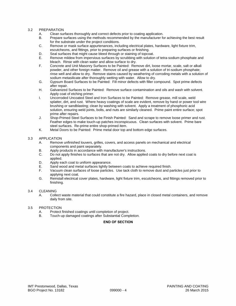
IMT Prestonwood, Dallas, Texas PAINTING AND COATING BGO Project No. 13182 099000 - 4 26 March 2015
3.2 PREPARATION A. Clean surfaces thoroughly and correct defects prior to coating application. B. Prepare surfaces using the methods recommended by the manufacturer for achieving the best result
for the substrate under the project conditions. C. Remove or mask surface appurtenances, including electrical plates, hardware, light fixture trim,
escutcheons, and fittings, prior to preparing surfaces or finishing. D. Seal surfaces that might cause bleed through or staining of topcoat. E. Remove mildew from impervious surfaces by scrubbing with solution of tetra-sodium phosphate and
bleach. Rinse with clean water and allow surface to dry. F. Concrete and Unit Masonry Surfaces to be Painted: Remove dirt, loose mortar, scale, salt or alkali
powder, and other foreign matter. Remove oil and grease with a solution of tri-sodium phosphate; rinse well and allow to dry. Remove stains caused by weathering of corroding metals with a solution of sodium metasilicate after thoroughly wetting with water. Allow to dry.
G. Gypsum Board Surfaces to be Painted: Fill minor defects with filler compound. Spot prime defects after repair.
H. Galvanized Surfaces to be Painted: Remove surface contamination and oils and wash with solvent. Apply coat of etching primer.
I. Uncorroded Uncoated Steel and Iron Surfaces to be Painted: Remove grease, mill scale, weld splatter, dirt, and rust. Where heavy coatings of scale are evident, remove by hand or power tool wire brushing or sandblasting; clean by washing with solvent. Apply a treatment of phosphoric acid solution, ensuring weld joints, bolts, and nuts are similarly cleaned. Prime paint entire surface; spot prime after repairs.
J. Shop-Primed Steel Surfaces to be Finish Painted: Sand and scrape to remove loose primer and rust. Feather edges to make touch-up patches inconspicuous. Clean surfaces with solvent. Prime bare steel surfaces. Re-prime entire shop-primed item.
K. Metal Doors to be Painted: Prime metal door top and bottom edge surfaces.
3.3 APPLICATION A. Remove unfinished louvers, grilles, covers, and access panels on mechanical and electrical
components and paint separately. B. Apply products in accordance with manufacturer's instructions. C. Do not apply finishes to surfaces that are not dry. Allow applied coats to dry before next coat is
applied. D. Apply each coat to uniform appearance. E. Sand wood and metal surfaces lightly between coats to achieve required finish. F. Vacuum clean surfaces of loose particles. Use tack cloth to remove dust and particles just prior to
applying next coat. G. Reinstall electrical cover plates, hardware, light fixture trim, escutcheons, and fittings removed prior to
finishing.
3.4 CLEANING A. Collect waste material that could constitute a fire hazard, place in closed metal containers, and remove
daily from site.
3.5 PROTECTION A. Protect finished coatings until completion of project. B. Touch-up damaged coatings after Substantial Completion.
END OF SECTION

IMT Prestonwood, Dallas, Texas ELASTOMERIC COATING BGO Project No. 13182 099450 - 1 26 March 2015
SECTION 099450
ELASTOMERIC COATING
PART 1 GENERAL
1.1 SUMMARY A. Section Includes:
1. Elastomeric coating on exterior elevations of parking garage perimeter walls and columns.
1.2 SUBMITTALS A. Submit samples of colors and textures available to Owner’s Representative for selection in accordance
with Section 013000. B. Submit manufacturer's product data and installation instructions.
1.3 DELIVERY AND STORAGE A. Deliver and store materials in accordance with the requirements of Sections 016000. B. Deliver materials in original containers with seals unbroken and labels intact. C. Store materials and equipment in a protected, climate controlled area of project site. D. Comply with applicable health and fire regulations.
1.4 SCAFFOLDS AND PROTECTION A. Provide adequate, safe ladders, scaffolds and stages necessary to complete work. B. Protect completed finish coating work and adjacent finish surfaces from coating splatter, spills and
stains. Use adequate drop cloths and masking procedures during progress of work.
PART 2 PRODUCTS
2.1 MANUFACTURERS AND PRODUCTS A. Acceptable Products: Subject to compliance with requirements herein, provide one of the following
products: 1. Sherwin Williams; Sherlastic.
B. Substitutions: Provided product meets requirements indicated herein, submit in accordance with Section 016000.
2.2 PRODUCTS A. Composition and Materials: Elastomeric, high-build, acrylic polymer based coating, pre-mixed,
breathable, not less than 20. B. Thickness: Apply at the rate of as otherwise recommended by manufacturer. C. Color: Refer to Finish Legend D. Primer: Type as required by manufacturer for substrate encountered.
PART 3 EXECUTION
3.1 INSPECTION A. Examine surfaces scheduled to receive coating for conditions that will adversely affect execution,
perseverance, or quality of finish work, and which cannot be put into an acceptable condition through normal preparatory work.
B. Surfaces must be clean.
3.2 PREPARATION A. Chip or grind off all defective materials and foreign matter. B. Remove form treatment residue, curing compound, scum and fungus. Water blast if required by
manufacturer. C. Repair cracks, breaks, honeycombing, or other surface imperfections with non-expansive patching
mortar to attain a finish comparable to adjacent concrete surfaces. D. Notify Owner’s Representative in writing of such unacceptable conditions. E. Do not proceed with surface preparation or coating applications until conditions are suitable. F. Application of coating or finish to surfaces shall constitute acceptance of that surface.
IMT Prestonwood, Dallas, Texas ELASTOMERIC COATING BGO Project No. 13182 099450 - 2 26 March 2015
3.3 APPLICATION A. The intent of these specifications is to produce the highest quality appearance coating and finish
surfaces. Employ skilled mechanics only. Comply with manufacturer's printed specifications for application. Allow repairs to properly cure before beginning installation.
B. Do not apply exterior coatings while surface is damp, or during cold, rainy, or frosty weather, or when temperature is below 40 degrees F. nor under conditions where temperature may drop below 40 degrees F. within 24 hours after application. Cool surfaces exposed to hot sun by hosing with clean water.
C. Spray apply primer as recommended by manufacturer. D. Work primer into surface as recommended by manufacturer. E. Spray apply finish coat to thickness as recommended by manufacturer. F. Ensure that finished surfaces are uniform in texture, color and thickness without noticeable "overspray"
marks.
3.4 CLEAN UP A. Remove debris and empty curtains from site ate the end of each days work or as often as deemed
necessary. B. Remove any irregularities from the face of the wall and patch as required.
END OF SECTION
IMT Prestonwood, Dallas, Texas SIGNAGE BGO Project No. 13182 101400 - 1 26 March 2015
SECTION 101400
SIGNAGE
PART 1 GENERAL
1.1 SECTION INCLUDES A. Interior code required signage. B. Room and door signs. C. Handicapped parking signs.
1.2 SUBMITTALS A. See Section 013000 - Administrative Requirements, for submittal procedures. B. Product Data: Manufacturer's printed product literature for each type of sign, indicating sign styles,
font, foreground and background colors, locations, overall dimensions of each sign. C. Signage Schedule: Provide information sufficient to completely define each sign for fabrication,
including room number, room name, other text to be applied, sign and letter sizes, fonts, and colors. 1. When room numbers to appear on signs differ from those on the drawings, include the drawing
room number on schedule. 2. When content of signs is indicated to be determined later, request such information from Owner
through Architect at least 2 months prior to start of fabrication; upon request, submit preliminary schedule.
3. Submit for approval by Owner through Architect prior to fabrication. D. Samples: Submit two samples of each type of sign, of size similar to that required for project,
illustrating sign style, font, and method of attachment.
1.3 QUALITY ASSURANCE A. Manufacturer Qualifications: Company specializing in manufacturing the products specified in this
section with minimum three years of documented experience.
1.4 DELIVERY, STORAGE, AND HANDLING A. Package signs as required to prevent damage before installation. B. Package room and door signs in sequential order of installation, labeled by floor or building. C. Store tape adhesive at normal room temperature.
1.5 FIELD CONDITIONS A. Do not install tape adhesive when ambient temperature is lower than recommended by manufacturer. B. Maintain this minimum temperature during and after installation of signs.
PART 2 PRODUCTS
2.1 MANUFACTURERS A. Flat Signs:
1. Best Sign Systems, Inc: www.bestsigns.com. 2. InPro Corporation: www.inprocorp.com. 3. Mohawk Sign Systems, Inc: www.mohawksign.com. 4. Seton Identification Products: www.seton.com/aec.
2.2 SIGNAGE APPLICATIONS A. Accessibility Compliance: All signs are required to comply with ADA Standards for Accessible Design
and ANSI/ICC A 117.1 and applicable building codes, unless otherwise indicated; in the event of conflicting requirements, comply with the most comprehensive and specific requirements.
B. Room and Door Signs: Provide a sign for every doorway, whether it has a door or not, not including corridors, lobbies, and similar open areas. 1. Sign Type: Flat signs with engraved panel media as specified. 2. Provide "tactile" signage, with letters raised minimum 1/32 inch and Grade II braille. 3. Character Height: 1 inch. 4. Sign Height: 2 inches, unless otherwise indicated. 5. Rest Rooms: Identify with pictograms, the names "MEN" and "WOMEN", room numbers to be
determined later, and braille.
IMT Prestonwood, Dallas, Texas SIGNAGE BGO Project No. 13182 101400 - 2 26 March 2015
2.3 SIGN TYPES A. Flat Signs: Signage media without frame.
1. Edges: Square. 2. Corners: Square. 3. Wall Mounting of One-Sided Signs: Tape adhesive.
B. Color and Font: Unless otherwise indicated: 1. Character Font: Helvetica, Arial, or other sans serif font. 2. Character Case: Upper case only. 3. Background Color: As scheduled. 4. Character Color: Contrasting color.
2.4 TACTILE SIGNAGE MEDIA A. Engraved Panels: Laminated colored plastic; engraved through face to expose core as background
color: 1. Total Thickness: 1/16 inch.
2.5 HANDICAPPED PARKING SIGNS A. Screen printed, 18 gage bonderized steel with blue baked enamel finish and white screen printed copy. B. Size: 12 inches by 18 inches and 12 inches by 6 inches. C. Copy:
1. "Handicapped Parking Only". 2. "Van Accessible".
D. Acceptable Products: Handicapped Parking: Best Traffic Signs No. SS04 with SS52 as required. E. Post: Galvanized pipe column minimum 9 feet long.
2.6 ACCESSORIES A. Tape Adhesive: Double sided tape, permanent adhesive.
PART 3 EXECUTION
3.1 EXAMINATION A. Verify that substrate surfaces are ready to receive work.
3.2 INSTALLATION A. Install in accordance with manufacturer's instructions. B. Install neatly, with horizontal edges level. C. Locate signs where indicated:
1. Room and Door Signs: Locate on wall at latch side of door with centerline of sign at 60 inches above finished floor.
2. If no location is indicated obtain Owner's instructions. D. Protect from damage until Substantial Completion; repair or replace damage items.
END OF SECTION
IMT Prestonwood, Dallas, Texas SHOWER AND TUB ENCLOSURES BGO Project No. 13182 101850 - 1 26 March 2015
SECTION 101850
SHOWER AND TUB ENCLOSURES
PART 1 - GENERAL
1.1 SECTION INCLUDES A. Shower pans.
1.2 SUBMITTALS A. Submit under provisions of Section 013000. B. Product Data: Manufacturer's data sheets on each product to be used, including:
1. Preparation instructions and recommendations. 2. Storage and handling requirements and recommendations. 3. Installation methods.
C. Selection Samples: For each finish product specified, two complete sets of color chips representing manufacturer's full range of available colors and patterns.
D. Verification Samples: For each finish product specified, two samples, minimum size 6 inches (150 mm) square, representing actual product, color, and patterns.
E. Manufacturer's Certificates: Certify products meet or exceed specified requirements.
1.3 QUALITY ASSURANCE A. Manufacturer Qualifications: A manufacturer with a minimum of ten years experience manufacturing bath
and shower components. B. Installer Qualifications: An installer who has demonstrated experience installing bath and shower
components and as recommended by the manufacturer.
1.4 DELIVERY, STORAGE, AND HANDLING A. Store products in manufacturer's unopened packaging until ready for installation.
1.5 PROJECT CONDITIONS A. Maintain environmental conditions (temperature, humidity, and ventilation) within limits recommended by
manufacturer for optimum results. Do not install products under environmental conditions outside manufacturer's absolute limits.
1.6 WARRANTY A. Provide manufacturer's standard 5-year limited warranty.
PART 2 - PRODUCTS
2.1 MANUFACTURERS A. Acceptable Manufacturers:
1. American Bath Enterprises, Inc. www.americanbathind.com 2. Clarion Bathware, www.clarionbathware.com. 3. Sterling Division of Kohler.
B. Requests for substitutions will be considered in accordance with provisions of Section 012500.
2.2 ACCEPTABLE PRODUCTS A. Shower Receptor:
1. Sterling model as required to match size on Drawings.
PART 3 - EXECUTION
3.1 EXAMINATION A. Do not begin installation until substrates have been properly prepared. B. If substrate preparation is the responsibility of another installer, notify Architect of unsatisfactory
preparation before proceeding.

IMT Prestonwood, Dallas, Texas SHOWER AND TUB ENCLOSURES BGO Project No. 13182 101850 - 2 26 March 2015
3.2 PREPARATION A. Clean surfaces thoroughly prior to installation. B. Prepare surfaces using the methods recommended by the manufacturer for achieving the best result for
the substrate under the project conditions.
3.3 INSTALLATION A. Install in accordance with manufacturer's instructions.
3.4 PROTECTION A. Protect installed products until completion of project. B. Touch-up, repair or replace damaged products before Substantial Completion.
END OF SECTION
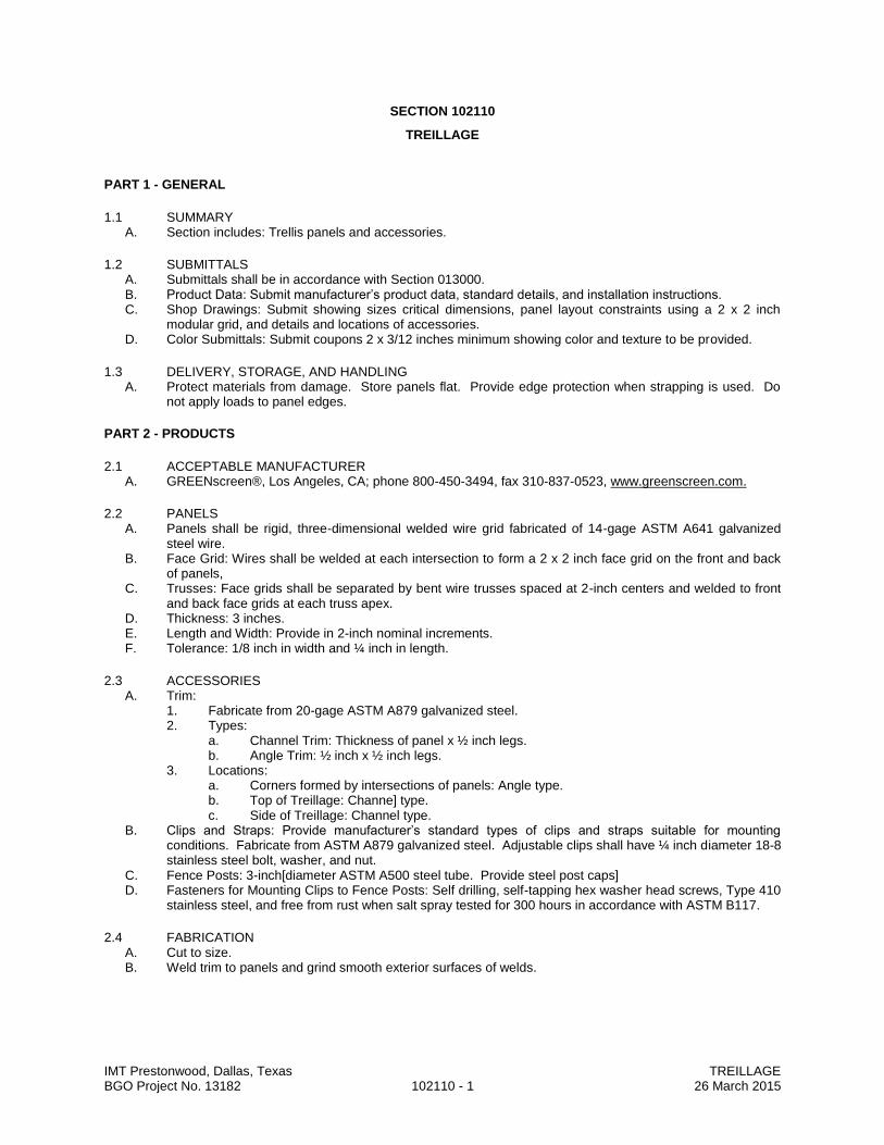
IMT Prestonwood, Dallas, Texas TREILLAGE BGO Project No. 13182 102110 - 1 26 March 2015
SECTION 102110
TREILLAGE
PART 1 - GENERAL
1.1 SUMMARY A. Section includes: Trellis panels and accessories.
1.2 SUBMITTALS A. Submittals shall be in accordance with Section 013000. B. Product Data: Submit manufacturer’s product data, standard details, and installation instructions. C. Shop Drawings: Submit showing sizes critical dimensions, panel layout constraints using a 2 x 2 inch
modular grid, and details and locations of accessories. D. Color Submittals: Submit coupons 2 x 3/12 inches minimum showing color and texture to be provided.
1.3 DELIVERY, STORAGE, AND HANDLING A. Protect materials from damage. Store panels flat. Provide edge protection when strapping is used. Do
not apply loads to panel edges.
PART 2 - PRODUCTS
2.1 ACCEPTABLE MANUFACTURER A. GREENscreen®, Los Angeles, CA; phone 800-450-3494, fax 310-837-0523, www.greenscreen.com.
2.2 PANELS A. Panels shall be rigid, three-dimensional welded wire grid fabricated of 14-gage ASTM A641 galvanized
steel wire. B. Face Grid: Wires shall be welded at each intersection to form a 2 x 2 inch face grid on the front and back
of panels, C. Trusses: Face grids shall be separated by bent wire trusses spaced at 2-inch centers and welded to front
and back face grids at each truss apex. D. Thickness: 3 inches. E. Length and Width: Provide in 2-inch nominal increments. F. Tolerance: 1/8 inch in width and ¼ inch in length.
2.3 ACCESSORIES A. Trim:
1. Fabricate from 20-gage ASTM A879 galvanized steel. 2. Types:
a. Channel Trim: Thickness of panel x ½ inch legs. b. Angle Trim: ½ inch x ½ inch legs.
3. Locations: a. Corners formed by intersections of panels: Angle type. b. Top of Treillage: Channe] type. c. Side of Treillage: Channel type.
B. Clips and Straps: Provide manufacturer’s standard types of clips and straps suitable for mounting conditions. Fabricate from ASTM A879 galvanized steel. Adjustable clips shall have ¼ inch diameter 18-8 stainless steel bolt, washer, and nut.
C. Fence Posts: 3-inch[diameter ASTM A500 steel tube. Provide steel post caps] D. Fasteners for Mounting Clips to Fence Posts: Self drilling, self-tapping hex washer head screws, Type 410
stainless steel, and free from rust when salt spray tested for 300 hours in accordance with ASTM B117.
2.4 FABRICATION A. Cut to size. B. Weld trim to panels and grind smooth exterior surfaces of welds.
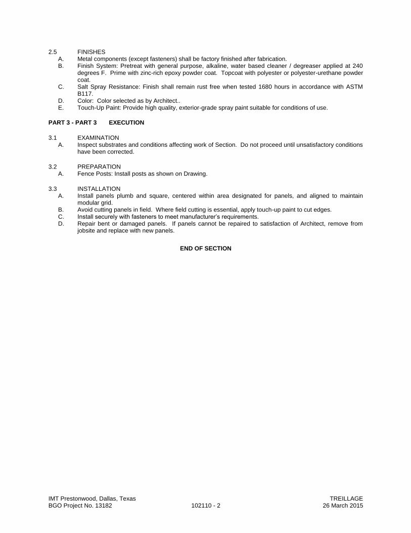
IMT Prestonwood, Dallas, Texas TREILLAGE BGO Project No. 13182 102110 - 2 26 March 2015
2.5 FINISHES A. Metal components (except fasteners) shall be factory finished after fabrication. B. Finish System: Pretreat with general purpose, alkaline, water based cleaner / degreaser applied at 240
degrees F. Prime with zinc-rich epoxy powder coat. Topcoat with polyester or polyester-urethane powder coat.
C. Salt Spray Resistance: Finish shall remain rust free when tested 1680 hours in accordance with ASTM B117.
D. Color: Color selected as by Architect.. E. Touch-Up Paint: Provide high quality, exterior-grade spray paint suitable for conditions of use.
PART 3 - PART 3 EXECUTION
3.1 EXAMINATION A. Inspect substrates and conditions affecting work of Section. Do not proceed until unsatisfactory conditions
have been corrected.
3.2 PREPARATION A. Fence Posts: Install posts as shown on Drawing.
3.3 INSTALLATION A. Install panels plumb and square, centered within area designated for panels, and aligned to maintain
modular grid. B. Avoid cutting panels in field. Where field cutting is essential, apply touch-up paint to cut edges. C. Install securely with fasteners to meet manufacturer’s requirements. D. Repair bent or damaged panels. If panels cannot be repaired to satisfaction of Architect, remove from
jobsite and replace with new panels.
END OF SECTION

IMT Prestonwood, Dallas, Texas TOILET COMPARTMENTS BGO Project No. 13182 102113 - 1 26 March 2015
SECTION 102113
TOILET COMPARTMENTS
PART 1 - GENERAL
1.1 RELATED DOCUMENTS A. Drawings and general provisions of the Contract, including General and Supplementary Conditions and
Division 01 Specification Sections, apply to this Section.
1.2 SUMMARY A. Section Includes:
1. Toilet compartments configured as toilet enclosures and urinal screens.
1.3 SUBMITTALS A. Product Data: For each type of product indicated. Include construction details, material descriptions,
dimensions of individual components and profiles, and finishes. B. Shop Drawings: For toilet compartments. Include plans, elevations, sections, details, and attachments to
other work. 1. Show locations of cutouts for compartment-mounted toilet accessories. 2. Show locations of reinforcements for compartment-mounted grab bars. 3. Show locations of centerlines of toilet fixtures. 4. Show overhead support or bracing locations.
1.4 QUALITY ASSURANCE A. Comply with requirements in GSA's CID-A-A-60003, "Partitions, Toilets, Complete”, August 1997 current
version. B. Surface-Burning Characteristics: As determined by testing identical products according to ASTM E 84, or
another standard acceptable to authorities having jurisdiction, by a qualified testing agency. Identify products with appropriate markings of applicable testing agency. 1. Flame-Spread Index: 25 or less. 2. Smoke-Developed Index: 450 or less.
C. Regulatory Requirements: Comply with applicable provisions in the U.S. Architectural & Transportation Barriers Compliance Board's "Americans with Disabilities Act (ADA) and Architectural Barriers Act (ABA) Accessibility Guidelines for Buildings and Facilities" for toilet compartments designated as accessible.
1.5 PROJECT CONDITIONS A. Field Measurements: Verify actual locations of toilet fixtures, walls, columns, ceilings, and other
construction contiguous with toilet compartments by field measurements before fabrication.
1.6 WARRANTY A. Fifteen (15) years against rust-out.
PART 2 - PRODUCTS
2.1 MATERIALS A. Aluminum Castings: ASTM B 26. B. Aluminum Extrusions: ASTM B 22. C. Steel Sheet: Commercial steel sheet for exposed applications; mill phosphatized and selected for
smoothness. 1. Electrolytically Zinc Coated: ASTM A 879, 01Z. 2. Hot-Dip Galvanized: ASTM A 653, either hot-dip galvanized or galvannealed.
D. Stainless-Steel Sheet: ASTM A 666, Type 304, stretcher-leveled standard of flatness. E. Stainless-Steel Castings: ASTM A 743. F. Zamac: ASTM B 86, commercial zinc-alloy die castings. G. Particleboard: ANSI A208.1, Grade M-2 with 45-lb ()density, made with binder containing no urea
formaldehyde. H. Plastic Laminate: NEMA LD 3, general-purpose HGS grade, 0.048-inch nominal thickness.
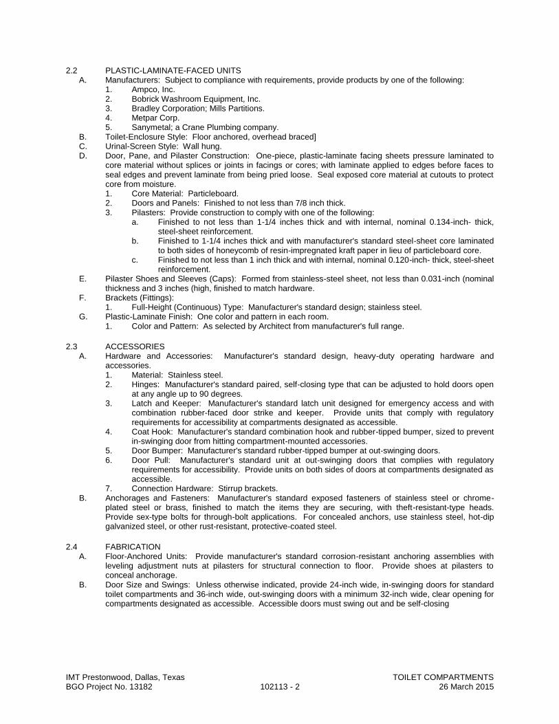
IMT Prestonwood, Dallas, Texas TOILET COMPARTMENTS BGO Project No. 13182 102113 - 2 26 March 2015
2.2 PLASTIC-LAMINATE-FACED UNITS A. Manufacturers: Subject to compliance with requirements, provide products by one of the following:
1. Ampco, Inc. 2. Bobrick Washroom Equipment, Inc. 3. Bradley Corporation; Mills Partitions. 4. Metpar Corp. 5. Sanymetal; a Crane Plumbing company.
B. Toilet-Enclosure Style: Floor anchored, overhead braced] C. Urinal-Screen Style: Wall hung. D. Door, Pane, and Pilaster Construction: One-piece, plastic-laminate facing sheets pressure laminated to
core material without splices or joints in facings or cores; with laminate applied to edges before faces to seal edges and prevent laminate from being pried loose. Seal exposed core material at cutouts to protect core from moisture. 1. Core Material: Particleboard. 2. Doors and Panels: Finished to not less than 7/8 inch thick. 3. Pilasters: Provide construction to comply with one of the following:
a. Finished to not less than 1-1/4 inches thick and with internal, nominal 0.134-inch- thick, steel-sheet reinforcement.
b. Finished to 1-1/4 inches thick and with manufacturer's standard steel-sheet core laminated to both sides of honeycomb of resin-impregnated kraft paper in lieu of particleboard core.
c. Finished to not less than 1 inch thick and with internal, nominal 0.120-inch- thick, steel-sheet reinforcement.
E. Pilaster Shoes and Sleeves (Caps): Formed from stainless-steel sheet, not less than 0.031-inch (nominal thickness and 3 inches (high, finished to match hardware.
F. Brackets (Fittings): 1. Full-Height (Continuous) Type: Manufacturer's standard design; stainless steel.
G. Plastic-Laminate Finish: One color and pattern in each room. 1. Color and Pattern: As selected by Architect from manufacturer's full range.
2.3 ACCESSORIES A. Hardware and Accessories: Manufacturer's standard design, heavy-duty operating hardware and
accessories. 1. Material: Stainless steel. 2. Hinges: Manufacturer's standard paired, self-closing type that can be adjusted to hold doors open
at any angle up to 90 degrees. 3. Latch and Keeper: Manufacturer's standard latch unit designed for emergency access and with
combination rubber-faced door strike and keeper. Provide units that comply with regulatory requirements for accessibility at compartments designated as accessible.
4. Coat Hook: Manufacturer's standard combination hook and rubber-tipped bumper, sized to prevent in-swinging door from hitting compartment-mounted accessories.
5. Door Bumper: Manufacturer's standard rubber-tipped bumper at out-swinging doors. 6. Door Pull: Manufacturer's standard unit at out-swinging doors that complies with regulatory
requirements for accessibility. Provide units on both sides of doors at compartments designated as accessible.
7. Connection Hardware: Stirrup brackets. B. Anchorages and Fasteners: Manufacturer's standard exposed fasteners of stainless steel or chrome-
plated steel or brass, finished to match the items they are securing, with theft-resistant-type heads. Provide sex-type bolts for through-bolt applications. For concealed anchors, use stainless steel, hot-dip galvanized steel, or other rust-resistant, protective-coated steel.
2.4 FABRICATION A. Floor-Anchored Units: Provide manufacturer's standard corrosion-resistant anchoring assemblies with
leveling adjustment nuts at pilasters for structural connection to floor. Provide shoes at pilasters to conceal anchorage.
B. Door Size and Swings: Unless otherwise indicated, provide 24-inch wide, in-swinging doors for standard toilet compartments and 36-inch wide, out-swinging doors with a minimum 32-inch wide, clear opening for compartments designated as accessible. Accessible doors must swing out and be self-closing

IMT Prestonwood, Dallas, Texas TOILET COMPARTMENTS BGO Project No. 13182 102113 - 3 26 March 2015
PART 3 - EXECUTION
3.1 INSTALLATION A. General: Comply with manufacturer's written installation instructions. Install units rigid, straight, level, and
plumb. Secure units in position with manufacturer's recommended anchoring devices. 1. Maximum Clearances:
a. Pilasters and Panels: 1/2 inch. b. Panels and Walls: 1 inch.
B. Floor-Anchored Units: Set pilasters with anchors penetrating not less than 2 inches (into structural floor unless otherwise indicated in manufacturer's written instructions. Level, plumb, and tighten pilasters. Hang doors and adjust so tops of doors are level with tops of pilasters when doors are in closed position.
C. Urinal Screens: Attach with anchoring devices to suit supporting structure. Set units level and plumb, rigid, and secured to resist lateral impact. Provide blocking or metal strapping in walls for anchorage support.
3.2 ADJUSTING A. Hardware Adjustment: Adjust and lubricate hardware according to hardware manufacturer's written
instructions for proper operation. Set hinges on in-swinging doors to hold doors open approximately 30 degrees from closed position when unlatched. Set hinges on out-swinging doors to return doors to fully closed position.
END OF SECTION
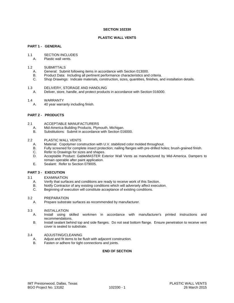
IMT Prestonwood, Dallas, Texas PLASTIC WALL VENTS BGO Project No. 13182 102330 - 1 26 March 2015
SECTION 102330
PLASTIC WALL VENTS
PART 1 - GENERAL
1.1 SECTION INCLUDES A. Plastic wall vents.
1.2 SUBMITTALS A. General: Submit following items in accordance with Section 013000. B. Product Data: Including all pertinent performance characteristics and criteria. C. Shop Drawings: Indicate materials, construction, sizes, quantities, finishes, and installation details.
1.3 DELIVERY, STORAGE AND HANDLING A. Deliver, store, handle, and protect products in accordance with Section 016000.
1.4 WARRANTY A. 40 year warranty including finish.
PART 2 - PRODUCTS
2.1 ACCEPTABLE MANUFACTURERS A. Mid-America Building Products, Plymouth, Michigan. B. Substitutions: Submit in accordance with Section 016000.
2.2 PLASTIC WALL VENTS A. Material: Copolymer construction with U.V. stabilized color molded throughout. B. Fully screened for complete insect protection; nailing flanges with pre-drilled holes; brush-grained finish. C. Refer to Drawings for sizes and shapes. D. Acceptable Product: GableMASTER Exterior Wall Vents as manufactured by Mid-America. Dampers to
remain operable after paint application. E. Sealant: Refer to Section 079005.
PART 3 - EXECUTION
3.1 EXAMINATION A. Verify that surfaces and conditions are ready to receive work of this Section. B. Notify Contractor of any existing conditions which will adversely affect execution. C. Beginning of execution will constitute acceptance of existing conditions.
3.2 PREPARATION A. Prepare substrate surfaces as recommended by manufacturer.
3.3 INSTALLATION A. Install using skilled workmen in accordance with manufacturer's printed instructions and
recommendations. B. Install sealant behind top and side flanges. Do not seal bottom flange. Ensure penetration to receive vent
cover is sealed to substrate.
3.4 ADJUSTING/CLEANING A. Adjust and fit items to be flush with adjacent construction. B. Fasten or adhere for tight connections and joints.
END OF SECTION
IMT Prestonwood, Dallas, Texas TOILET, BATH, AND LAUNDRY ACCESSORIES BGO Project No. 13182 102800 - 1 26 March 2015
SECTION 102800
TOILET, BATH, AND LAUNDRY ACCESSORIES
PART 1 GENERAL
1.1 SECTION INCLUDES A. Accessories for toilet rooms, residential bathrooms, and utility rooms. B. Grab bars.
1.2 ADMINISTRATIVE REQUIREMENTS A. Coordinate the work with the placement of internal wall reinforcement, concealed ceiling supports, and
reinforcement of toilet partitions to receive anchor attachments.
1.3 SUBMITTALS A. See Section 013000 - Administrative Requirements, for submittal procedures. B. Product Data: Provide data on accessories describing size, finish, details of function, attachment
methods. C. Samples: Submit two samples of each accessory, illustrating color and finish. D. Manufacturer's Installation Instructions: Indicate special procedures and conditions requiring special
attention.
PART 2 PRODUCTS
2.1 MANUFACTURERS A. Toilet Accessories:
1. A & J Washroom Accessories Inc: www.ajwashroom.com. 2. American Specialties, Inc: www.americanspecialties.com. 3. Bobrick: www.bobrick.com. 4. Bradley Corporation: www.bradleycorp.com. 5. Substitutions: Section 016000 - Product Requirements.
2.2 MATERIALS A. Accessories - General: Shop assembled, free of dents and scratches and packaged complete with
anchors and fittings, steel anchor plates, adapters, and anchor components for installation. 1. Grind welded joints smooth. 2. Fabricate units made of metal sheet of seamless sheets, with flat surfaces.
B. Keys: Provide 2 keys for each accessory to Owner ; master key all lockable accessories. C. Stainless Steel Sheet: ASTM A666 , Type 304. D. Stainless Steel Tubing: ASTM A269, Type 304 or 316. E. Mirror Glass: Float glass, ASTM C1036 Type I, Class 1, Quality Q2, with silvering, protective and
physical characteristics complying with ASTM C1503. F. Adhesive: Two component epoxy type, waterproof. G. Fasteners, Screws, and Bolts: Hot dip galvanized , tamper-proof , security type. H. Expansion Shields: Fiber, lead, or rubber as recommended by accessory manufacturer for component
and substrate.
2.3 FINISHES A. Stainless Steel: No. 4 satin brushed finish , unless otherwise noted.
IMT Prestonwood, Dallas, Texas TOILET, BATH, AND LAUNDRY ACCESSORIES BGO Project No. 13182 102800 - 2 26 March 2015
2.4 TOILET ROOM ACCESSORIES A. Toilet Paper Dispenser: Single roll, surface mounted bracket type, chrome-plated zinc alloy brackets ,
spindleless type for tension spring delivery designed to prevent theft of tissue roll. B. Combination Towel Dispenser/Waste Receptacle: Recessed flush with wall, stainless steel; seamless
wall flanges, continuous piano hinges , tumbler locks on upper and lower doors. 1. Waste receptacle liner: Reusable, heavy-duty vinyl. 2. Towel dispenser capacity: 400 C-fold. 3. Waste receptacle capacity: 4 gallons.
C. Soap Dispenser: Liquid soap dispenser, deck-mounted on vanity, with polyethylene container concealed below deck; piston and 4 inch spout of stainless steel with bright polished finish; chrome-plated deck escutcheon. 1. Minimum Capacity: 16 ounces.
D. Grab Bars: Stainless steel, 1-1/4 inches outside diameter, minimum 0.05 inch wall thickness, nonslip grasping surface finish, concealed flange mounting; 1-1/2 inches clearance between wall and inside of grab bar.
2.5 SHOWER AND TUB ACCESSORIES A. Shower Curtain Rod: Stainless steel tube, 1 inch outside diameter, 0.04 inch wall thickness, satin-
finished, withminimum 0.04 inch thick satin-finished stainless steel flanges, for installation with exposed fasteners, curved profile unless otherwise indicated. Provide radiused profile.
B. Wall-Mounted Soap Dish: Heavy duty, seamless stainless steel, surface-mounted with drain holes, without grab bar, satin finish; with concealed mechanical fastening suitable for substrate and backplate.
C. Towel Bars: Stainless steel Type 304, 3/4 inch square tubular bar; rectangular brackets, concealed attachment, satin finish. 1. Length: 24 inches.
D. Towel Ring: Stainless steel, 2-1/2 inch extension from wall, with 1/4 inch diameter trapezoidal shaped ring, rectangular-shaped bracket and backplate for concealed attachment, satin finish.
2.6 RESIDENTIAL ACCESSORIES A. Tumbler and Toothbrush Holder: Wall-mounted, stainless steel, 2-1/4 inch diameter tumbler hole, 2
toothbrush holes located on each side of tumbler hole, rectangular-shaped bracket and backplate for concealed attachment, satin finish.
B. Medicine Cabinet: One-piece construction of heavy-gage steel with factory-applied, gloss white, baked enamel finish, surface-mounted, satin finish stainless steel mirror frame , reversible type. 1. Shelves: Adjustable, aluminum or glass; provide not less than 3 shelves. 2. Door: Fitted with continuous piano-type hinge, shock-absorbing spring-and-rod door stop,
magnetized catch, right-hand swing.
2.7 UTILITY ROOM ACCESSORIES A. Combination Utility Shelf/Mop and Broom Holder: 0.05 inch thick stainless steel, Type 304, with 1/2
inch returned edges, 0.06 inch steel wall brackets. 1. Drying rod: Stainless steel, 1/4 inch diameter. 2. Hooks: 2, 0.06 inch stainless steel rag hooks at shelf front. 3. Mop/broom holders: 3 spring-loaded rubber cam holders at shelf front. 4. Length: Manufacturer's standard length for number of holders/hooks.
PART 3 EXECUTION
3.1 EXAMINATION A. Verify existing conditions before starting work. B. Verify exact location of accessories for installation. C. Verify that field measurements are as indicated on drawings.
3.2 PREPARATION A. Deliver inserts and rough-in frames to site for timely installation. B. Provide templates and rough-in measurements as required.
3.3 INSTALLATION A. Install accessories in accordance with manufacturers' instructions. B. Install plumb and level, securely and rigidly anchored to substrate. C. Mounting Heights and Locations: As required by accessibility regulations and as indicated on drawings
END OF SECTION

IMT Prestonwood, Dallas, Texas FIRE PROTECTION SPECIALTIES BGO Project No. 13182 104400 - 1 26 March 2015
SECTION 104400
FIRE PROTECTION SPECIALTIES
PART 1 GENERAL
1.1 SECTION INCLUDES A. Fire extinguishers. B. Fire extinguisher cabinets. C. Accessories.
1.2 SUBMITTALS A. See Section 013000 - Administrative Requirements, for submittal procedures. B. Shop Drawings: Indicate cabinet physical dimensions, rough-in measurements for recessed cabinets,
and wall bracket mounted measurements. C. Product Data: Provide extinguisher operational features and anchorage details. D. Manufacturer's Installation Instructions: Indicate special criteria and wall opening coordination
requirements. E. Manufacturer's Certificate: Certify that products meet or exceed specified requirements. F. Maintenance Data: Include test, refill or recharge schedules and re-certification requirements.
1.3 FIELD CONDITIONS A. Do not install extinguishers when ambient temperature may cause freezing of extinguisher ingredients.
PART 2 PRODUCTS
2.1 MANUFACTURERS A. Fire Extinguishers:
1. Ansul, Inc : www.ansul.com. 2. JL Industries, Inc: www.jlindustries.com. 3. Pyro-Chem : www.pyrochem.com. 4. Substitutions: See Section 016000 - Product Requirements.
B. Fire Extinguisher Cabinets and Accessories: 1. JL Industries, Inc : www.jlindustries.com. 2. Larsen's Manufacturing Co : www.larsensmfg.com. 3. Potter-Roemer : www.potterroemer.com. 4. Substitutions: See Section 016000 - Product Requirements.
2.2 FIRE EXTINGUISHERS A. Fire Extinguishers - General: Comply with product requirements of NFPA 10 and applicable codes,
whichever is more stringent. 1. Provide extinguishers labeled by UL for the purpose specified and indicated.
B. Dry Chemical Type Fire Extinguishers: Carbon steel tank, with pressure gage. 1. Class: A:B:C. 2. Size: 10 pound. 3. Finish: Baked polyester powder coat, color as selected.
2.3 FIRE EXTINGUISHER CABINETS A. Metal: Formed prefinished sheet steel, 0.036 inch (0.9mm) thick. B. Cabinet Configuration: Semi-recessed type.
1. Sized to accommodate accessories. 2. Trim: Returned to wall surface, with 2-1/2 inch projection.
C. Door: 0.036 inch thick, reinforced for flatness and rigidity; latch. Hinge doors for 180 degree opening with two butt hinge. Provide nylon catch.
D. Door Glazing: Glass, clear, 1/8 inch thick float. Set in resilient channel gasket glazing. E. Cabinet Mounting Hardware: Appropriate to cabinet. Pre-drill for anchors. F. Weld, fill, and grind components smooth. G. Finish of Cabinet Exterior Trim and Door: Baked enamel, color as selected. H. Finish of Cabinet Interior: White enamel.

IMT Prestonwood, Dallas, Texas FIRE PROTECTION SPECIALTIES BGO Project No. 13182 104400 - 2 26 March 2015
2.4 ACCESSORIES A. Extinguisher Brackets: Formed steel, galvanized and enamel finished.
PART 3 EXECUTION
3.1 EXAMINATION A. Verify existing conditions before starting work.
3.2 INSTALLATION A. Install in accordance with manufacturer's instructions. B. Install cabinets plumb and level in wall openings, from finished floor to height as needed to meet
accessiblity requirements. C. Secure rigidly in place. D. Place extinguishers and accessories in cabinets.
END OF SECTION

IMT Prestonwood, Dallas, Texas MAIL BOXES BGO Project No. 13182 105523 - 1 26 March 2015
SECTION 105523
MAIL BOXES
PART 1 GENERAL
1.1 SECTION INCLUDES A. Multiple mail boxes with hinged and locked doors.
1.2 SUBMITTALS A. See Section 013000 - Administrative Requirements, for submittal procedures. B. Product Data: Provide data for components. C. Shop Drawings: Indicate locations, construction and anchorage details, dimensions, rough-in openings
sizes, quantity and arrangement of box sizes. 1. Show field measurements on shop drawings.
D. Manufacturer's Instructions: Include installation procedures, special considerations, and maintenance information.
E. Manufacturer's Certificate: Certify that products meet or exceed specified requirements.
1.3 QUALITY ASSURANCE A. Manufacturer Qualifications: Company specializing in manufacturing products specified in this section,
with not less than three years of documented experience.
PART 2 PRODUCTS
2.1 MANUFACTURERS A. Mail Boxes:
1. Auth-Florence Manufacturing Company: www.authflorence.com. 2. Bommer Industries, Inc: www.bommer.com. 3. Salsbury Industries: www.mailboxes.com. 4. Substitutions: See Section 016000 - Product Requirements.
2.2 MAIL BOXES SERVED BY U.S. POSTAL SERVICE A. Comply with U.S. Postal Service Standard 4C. B. Box Sizes: As indicated on drawings.
2.3 COMPONENTS A. Front Loading Panel Frame:
1. Aluminum with mill finish. 2. Edges beveled, piano hinged jamb, prepared for Post Office lock cylinder.
B. Box Door: 1. Plastic label installed to rear face. 2. Edges beveled, piano hinged jamb, prepared for lock cylinder.
C. Box Construction: Sheet steel, zinc coated, 22 gage thick, fabricated into modular stackable units, baked enamel flat black finish. Pre-punch bolt holes in box for stack bolting to each other and anchoring to adjacent construction; label plates for identifying each box.
D. Box Sizes: Configured as indicated on Drawings. E. Postal Box Locks: Five pin tumbler lock cylinder, two keys per box, cylinders master keyed to group
with two master keys. F. "Out-Going Mail" Lock Box: Face plate to match front loading panel frame, box of galvanized steel
construction, lockable with cylinder provided by Post Office, with bag hooks for rear unloading.

IMT Prestonwood, Dallas, Texas MAIL BOXES BGO Project No. 13182 105523 - 2 26 March 2015
PART 3 EXECUTION
3.1 EXAMINATION A. Verify that field measurements are as indicated. B. Verify that prepared openings are ready to receive work.
3.2 INSTALLATION A. Install in accordance with manufacturer's instructions and U.S. Postal Service regulations. B. Install and secure boxes in position, neatly, and accurately stacked. C. Install doors and adjust to operate smoothly.
END OF SECTION

IMT Prestonwood, Dallas, Texas WIRE STORAGE SHELVING BGO Project No. 13182 105623 - 1 26 March 2015
SECTION 105623
WIRE STORAGE SHELVING
PART 1 GENERAL
1.1 SECTION INCLUDES A. Wall mounted wire closet shelving. B. Accessories.
1.2 SUBMITTALS A. See Section 013000 - Administrative Requirements, for submittal procedures. B. Product Data: Manufacturer's data sheets on each product to be used, with installation instructions. C. Shop Drawings: Provide drawings prepared specifically for this project; show dimensions of shelving
and attachment to substrates. D. Selection Samples: For each color selection required, submit color chips representing manufacturer's
full range of available colors and finish.
1.3 QUALITY ASSURANCE A. Manufacturer Qualifications: Company specializing in manufacturing products specified in this section,
with not less than three years of documented experience.
1.4 DELIVERY, STORAGE, AND HANDLING A. Store products in manufacturer's unopened packaging until ready for installation. B. Store products under cover and elevated above grade. C. Store flat to prevent warpage and bending.
PART 2 PRODUCTS
2.1 MANUFACTURERS A. Wire Storage Shelving:
1. ClosetMaid Corporation: www.closetmaid.com. 2. RubberMaid Closet and Organization Products: www.rubbermaidcloset.com. 3. Substitutions: See Section 016000 - Product Requirements.
2.2 SHELVING APPLICATIONS A. Shelf Depth: 12 inches, unless otherwise indicated. B. Bedroom Closets:
1. Shelving equipped with free sliding hanger rod C. Coat Closets:
1. Wall-to-wall shelf with integral hanger rod.
2.3 MATERIALS A. Wire Shelving: Factory-assembled coated wire mesh shelf assemblies for wall-mounting, with all
components and connections required to produce a rigid structure that is free of buckling and warping. 1. Construction: Cold-drawn steel wire with average tensile strength of 100,000 psi resistance
welded into uniform mesh units, square, rigid, flat, and free of dents or other distortions, with wires trimmed smooth.
2. Coating: PVC or epoxy, applied after fabrication, covering all surfaces. 3. PVC Coating: 9 to 11 mils thick. 4. Epoxy Coating: Non-toxic epoxy-polyester powder coating baked-on finish, 3 to 5 mils thick. 5. Standard Mesh Shelves: Cross deck wires spaced at 1 inch. 6. Shelf and Rod Units: Integral hanging rod at front edge of shelf. 7. Free-Sliding Hanging Rod: Integral hanging rod that permits uninterrupted sliding of hangers
the full width of the shelf. B. Mounting Hardware: Provide manufacturer's standard mounting hardware; include support braces, wall
brackets, back clips, end clips, poles, and other accessories as required for complete and secure installation; factory finished to match shelving.
C. Fasteners: As recommended by manufacturer for mounting substrates.
IMT Prestonwood, Dallas, Texas WIRE STORAGE SHELVING BGO Project No. 13182 105623 - 2 26 March 2015
PART 3 EXECUTION
3.1 EXAMINATION A. Inspect areas to receive shelving, to verify that spaces are properly prepared to receive shelf units, and
are of dimensions indicated on shop drawings. B. Verify appropriate fastening hardware. C. Do not begin installation until substrates have been properly prepared. D. If substrate preparation is the responsibility of another installer, notify Architect of unsatisfactory
preparation before proceeding.
3.2 PREPARATION A. Clean surfaces thoroughly prior to installation. B. Prepare surfaces using the methods recommended by the manufacturer for achieving the best result
for the substrate under the project conditions.
3.3 INSTALLATION A. Install in accordance with manufacturer's instructions, with shelf surfaces level. B. Cap exposed ends of cut wires. C. Install back clips, end clips at side walls, and support braces at open ends. Install intermediate support
braces as recommended by manufacturer.
3.4 CLEANING A. Clean soiled surfaces after installation.
3.5 PROTECTION A. Protect installed work from damage. B. Touch-up, repair, or replace damaged products before Substantial Completion in a manner that
eliminates evidence of replacement.
END OF SECTION
IMT Prestonwood, Dallas, Texas FIXED ALUMINUM SUN SCREENS BGO Project No. 13182 107114 - 1 26 March 2015
SECTION 107114
FIXED ALUMINUM SUN SCREENS
PART 1 - GENERAL
1.1 RELATED DOCUMENTS A. Drawings and general provisions of the Contract, including General and Supplementary Conditions and
Division 01 Specification Sections, apply to this Section.
1.2 SUMMARY A. Section Includes:
1. Sun screen. 2. Reinforcing, shims, anchors, and attachment devices. 3. Accessories necessary to complete Work.
1.3 SYSTEM DESCRIPTION A. Design Requirements:
1. Manufacturer: Responsible for designing each system, including anchorage to structural system and necessary modifications to meet specified requirements and maintain visual design concepts.
2. Provide aluminum decorative screen systems, including necessary modifications to meet specified requirements and maintaining visual design concepts.
3. Perimeter Conditions: Allow for installation tolerances, expansion and contraction of adjacent materials, structural deflections, and sealant manufacturer's recommended joint design.
4. Drawings: Diagrammatic and do not purport to identify nor solve problems of thermal or structural movement, or anchorage.
5. Requirements Shown by Details: Establish basic dimension of unit, sight lines and profiles of members.
6. Attachments: Account for site peculiarities and expansion and contraction movements so there is no possibility of loosening, weakening and fracturing connection between units and building structure or between units themselves.
7. Anchors, Fasteners and Braces: Structurally stressed not more than 50 percent of allowable stress when maximum loads are applied.
8. Allow for expansion and contraction due to structural movement without detriment to appearance or performance.
9. Accommodate building structure deflections in connections to structure. B. Thermal Requirements: Accommodate expansion and contraction movement due to surface temperature
differential of 180 degrees F without causing buckling, stress on structural elements, reduction of performance or other detrimental effects.
1.4 ACTION SUBMITTALS A. Product Data: Submit for each manufactured product in accordance with Section 013300. B. Shop Drawings:
1. Submit drawings indicating elevations, detailed design, dimensions, member profiles, joint locations, arrangement of units, member connections, and thickness of various components.
2. Indicate: 3. Details of special shapes. 4. Reinforcing. 5. Anchorage system. 6. Interfacing with building construction. 7. Provisions for expansion and contraction. 8. Clearly indicate locations of exposed fasteners and joints for Architect's acceptance.
C. Samples: Submit samples indicating quality of finish in required colors on alloys used for work, 12 inches long for extrusions and 6 inches square for sheet materials.
1.5 INFORMATIONAL SUBMITTALS A. Informational Submittals: Submit manufacturer's Instructions.
1.6 DELIVERY, STORAGE, AND HANDLING A. Comply with following:
1. Protect finished surfaces to prevent damage.

IMT Prestonwood, Dallas, Texas FIXED ALUMINUM SUN SCREENS BGO Project No. 13182 107114 - 2 26 March 2015
2. Do not use adhesive papers or sprayed coatings which become firmly bonded when exposed to sun.
3. Do not leave coating residue on surfaces.
1.7 WARRANTY A. Submit warranty stating fluorocarbon (PVDF) coating finish will be free from fading more than 10 percent,
chalking, yellowing, peeling, cracking, pitting, corroding or non-uniformity of color, or gloss deterioration beyond manufacturer's descriptive standards for 20 years and agreeing to promptly correct defects.
PART 2 - PRODUCTS
2.1 ACCEPTABLE MANUFACTURERS A. Manufacturers:
1. The Airolite Company, Marrietta, OH 2. Construction Specialties, Cranford, NJ. 3. Arcadia.
B. Acceptable Substitutions: 1. Refer to Section 012500.
C. Acceptable Profile: Refer to Drawings.
2.2 FRAMING MATERIALS AND ACCESSORIES A. Aluminum:
1. ASTM B221, alloy 6063-T5 for extrusions; ASTM B209, alloy 5005-H16 for sheets; or other alloys and temper recommended by manufacturer appropriate for specified finish.
2. Minimum thickness of 0.081 inch for framing members and 0.050 inch for applied stops and similar components.
B. Inserts and Anchorage Devices: 1. Manufacturer's standard formed or fabricated assemblies, steel or aluminum, of shapes, plates,
bars or tubes. 2. Hot-dip galvanize steel assemblies after fabrication, comply with ASTM A123, 2.0 ounce minimum
coating. C. Fasteners: Non-magnetic stainless steel or cadmium plated steel coated with yellow or silver iridescence
plating, compatible with materials being fastened. 1. Exposed Locations: Series 300 stainless steel. 2. Concealed Locations: Cadmium plated steel with 0.0005 inch plating thickness and color
chromate coated. 3. Provide nuts or washers of design having means to prevent disengagement; deforming of fastener
threads is not acceptable. 4. Provide concealed fasteners wherever possible. 5. Exposed Locations: Countersunk flathead fasteners with finish matching item fastened.
D. Expansion Anchor Devices: Drilled-in, expansion bolt anchors. E. Shims: Non-staining, non-ferrous, type as recommended by system manufacturer. F. Protective Coatings: Cold applied asphalt mastic, SSPC-Paint 12, compounded for 30 mil thickness for
each coat; or alkyd type zinc chromate primer, FS TT-P-645.
2.3 FABRICATION A. Take accurate field measurements to verify required dimensions prior to fabrication.
1. Location of exposed joints is subject to Architect's acceptance. 2. Fabricate components in accordance with approved shop drawings. Remove burrs and ease
edges. Shop fabricate to greatest extent practicable to minimize field cutting, splicing, and assembly. Disassemble only to extent necessary for shipping and handling limitations.
B. Welding: Comply with recommendations of American Welding Society (AWS). 1. Performed by AWS qualified welders using recommended electrodes and methods to avoid
distortion and discoloration. 2. Grind exposed welds smooth and flush with adjacent surfaces before finishing; restore mechanical
finish.
2.4 FINISH A. General: Comply with Aluminum Association's (AA) "Designation System for Aluminum Finishes" for
finish designations and application recommendations. B. Aluminum: Finish designations prefixed by AA comply with the system established by the Aluminum
Association for designating aluminum finishes.

IMT Prestonwood, Dallas, Texas FIXED ALUMINUM SUN SCREENS BGO Project No. 13182 107114 - 3 26 March 2015
C. Clear Anodic Finish: AAMA 611, AA-M12C22A41, Class I, 0.018 mm or thicker. D. Color Anodic Finish: AAMA 611, [AA-M12C22A42/A44, Class I, 0.018 mm] [AA-M12C22A32/A34, Class
II, 0.010 mm] or thicker. 1. Color: [Light bronze] [Medium bronze] [Dark bronze] [Champagne] [Black] [Insert color].
E. High-Performance Organic Finish: Two-coat fluoropolymer finish complying with AAMA 2605 and containing not less than 70 percent PVDF resin by weight in color coat. Prepare, pretreat, and apply coating to exposed metal surfaces to comply with coating and resin manufacturers' written instructions. 1. Color and Gloss: As selected by Architect from manufacturer's full range.
PART 3 - EXECUTION
3.1 EXAMINATION A. Examine conditions and proceed with Work when substrates are ready.
1. Verify dimensions, tolerances, and method of attachment with other Work.
3.2 INSTALLATION A. Align assemblies plumb and level, free of warp or twist, aligning with adjacent Work. B. Tolerances: Tolerances are not accumulative.
1. Limit Variations from Plumb and Level: a. 1/8 inch in 20 feet vertically and horizontally. b. 1/4 inch in 40 feet either direction.
2. Jog in Alignment: 1/16 inch maximum. 3. Location: 1/4 inch maximum deviation of any member at any location.
C. Provide attachments and shims to permanently fasten system to building structure. 1. Anchor securely in place, allowing for required movement, including expansion and contraction. 2. Separate dissimilar materials at contract points, including metal in contact with masonry or
concrete surfaces, with protective coating or preformed separators to prevent contact and electrolytic action.
3.3 CLEANING A. General: Clean surfaces in compliance with manufacturer's recommendations; remove excess mastic,
mastic smears, and other foreign materials.
END OF SECTION
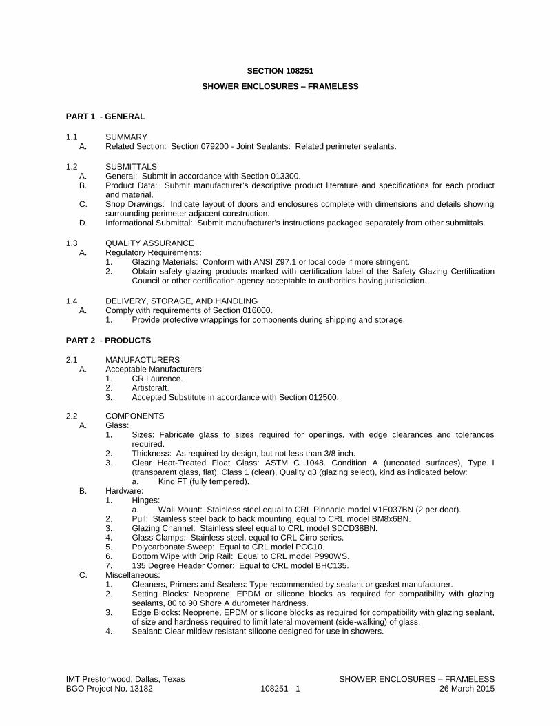
IMT Prestonwood, Dallas, Texas SHOWER ENCLOSURES – FRAMELESS BGO Project No. 13182 108251 - 1 26 March 2015
SECTION 108251
SHOWER ENCLOSURES – FRAMELESS
PART 1 - GENERAL
1.1 SUMMARY A. Related Section: Section 079200 - Joint Sealants: Related perimeter sealants.
1.2 SUBMITTALS A. General: Submit in accordance with Section 013300. B. Product Data: Submit manufacturer's descriptive product literature and specifications for each product
and material. C. Shop Drawings: Indicate layout of doors and enclosures complete with dimensions and details showing
surrounding perimeter adjacent construction. D. Informational Submittal: Submit manufacturer's instructions packaged separately from other submittals.
1.3 QUALITY ASSURANCE A. Regulatory Requirements:
1. Glazing Materials: Conform with ANSI Z97.1 or local code if more stringent. 2. Obtain safety glazing products marked with certification label of the Safety Glazing Certification
Council or other certification agency acceptable to authorities having jurisdiction.
1.4 DELIVERY, STORAGE, AND HANDLING A. Comply with requirements of Section 016000.
1. Provide protective wrappings for components during shipping and storage.
PART 2 - PRODUCTS
2.1 MANUFACTURERS
A. Acceptable Manufacturers: 1. CR Laurence. 2. Artistcraft. 3. Accepted Substitute in accordance with Section 012500.
2.2 COMPONENTS
A. Glass: 1. Sizes: Fabricate glass to sizes required for openings, with edge clearances and tolerances
required. 2. Thickness: As required by design, but not less than 3/8 inch. 3. Clear Heat-Treated Float Glass: ASTM C 1048. Condition A (uncoated surfaces), Type I
(transparent glass, flat), Class 1 (clear), Quality q3 (glazing select), kind as indicated below: a. Kind FT (fully tempered).
B. Hardware: 1. Hinges:
a. Wall Mount: Stainless steel equal to CRL Pinnacle model V1E037BN (2 per door). 2. Pull: Stainless steel back to back mounting, equal to CRL model BM8x6BN. 3. Glazing Channel: Stainless steel equal to CRL model SDCD38BN. 4. Glass Clamps: Stainless steel, equal to CRL Cirro series. 5. Polycarbonate Sweep: Equal to CRL model PCC10. 6. Bottom Wipe with Drip Rail: Equal to CRL model P990WS. 7. 135 Degree Header Corner: Equal to CRL model BHC135.
C. Miscellaneous: 1. Cleaners, Primers and Sealers: Type recommended by sealant or gasket manufacturer. 2. Setting Blocks: Neoprene, EPDM or silicone blocks as required for compatibility with glazing
sealants, 80 to 90 Shore A durometer hardness. 3. Edge Blocks: Neoprene, EPDM or silicone blocks as required for compatibility with glazing sealant,
of size and hardness required to limit lateral movement (side-walking) of glass. 4. Sealant: Clear mildew resistant silicone designed for use in showers.

IMT Prestonwood, Dallas, Texas SHOWER ENCLOSURES – FRAMELESS BGO Project No. 13182 108251 - 2 26 March 2015
2.3 ACCESSORIES A. Glazing and Sealing Compounds Between System Components: Type as recommended by
manufacturer. B. Joint Sealants Between System Components and Adjacent Finish Surfaces: Sanitary silicone sealant
specified in Section 079200.
2.4 FINISH A. Stainless Steel Frame: No. 4 Stainless Steel Finish: In accordance with Section 050510.
PART 3 - EXECUTION
3.1 EXAMINATION A. Examine conditions and proceed with Work in accordance with Section 017300.
1. Verify proper location of blocking and bracing in walls. 2. Do not begin Work until adequate support construction is in place and adjacent finish materials are
complete.
3.2 INSTALLATION A. Shower Doors: Install in accordance with Section 017300 and approved Shop Drawings.
1. Install plumb, level and square, and free from warp or twist while maintaining dimensional tolerances and alignment with surrounding construction.
2. Joint Sealants: Provide continuous sealant between shower enclosures and adjacent construction and tooled smooth.
3. Joint Sealants: See Section 079200 for sealing joints between system components and adjacent finishes.
3.3 ADJUSTING AND CLEANING A. Adjust door operation for smooth, quiet movement. B. Remove excessive sealants, glazing compounds, and labels. Clean and polish products upon completion
of Work.
END OF SECTION

IMT Prestonwood, Dallas, Texas MISCELLANEOUS SPECIALTIES BGO Project No. 13182 109900 - 1 26 March 2015
SECTION 109900
MISCELLANEOUS SPECIALTIES
PART 1 - GENERAL
1.1 RELATED DOCUMENTS
A. Provisions established within the Owner Contractor Agreement, Instruction to Bidders, Supplemental Conditions, Division 1 - General Requirements, and the Drawings are collectively applicable to this Section.
1.2 SECTION INCLUDES
A. Section Includes: Miscellaneous specialty items as listed herein.
1.3 SUBMITTALS
A. General: Submit following items in accordance with Section 01 3300.
B. Product Data: Including all pertinent performance characteristics and criteria.
C. Shop Drawings: Indicate materials, construction, sizes, quantities, finishes, and installation details.
D. Manufacturer's Instructions: For installation, maintenance, and repair.
1.4 DELIVERY, STORAGE AND HANDLING
A. Deliver, store, handle, and protect products in accordance with Section 01 6000.
PART 2 - PRODUCTS
2.1 PRODUCTS
A. Fire Control Key Box: Provide recessed fire department key control box, equal to model 3200 by Knox Box.
1. Provide Knox Locks as required by local fire department.
B. Trash Compactor: Marathon Mini M.A.C.
C. Bike Racks: Belson Outdoors, model H36-3-G-SF, quantity as indicated.
PART 3 - EXECUTION
3.1 EXAMINATION
A. Verify that surfaces and conditions are ready to receive work of this Section.
B. Notify Architect of any existing conditions which will adversely affect execution.
C. Beginning of execution will constitute acceptance of existing conditions.
3.2 PREPARATION
A. Prepare substrate surfaces as recommended by manufacturer.
3.3 INSTALLATION
A. Install using skilled workmen in accordance with manufacturer's printed instructions and recommendations.
3.4 ADJUSTING
A. Adjust and fit items to be flush with adjacent construction.
B. Fasten or adhere for tight connections and joints.
3.5 CLEANING
A. Perform final cleaning in accordance with Division 01 Section “Closeout Procedures”.
3.6 PROTECTION
A. Protect finished installation in accordance with Division 01 Section “Product Requirements”.
END OF SECTION

IMT Prestonwood, Dallas, Texas RESIDENTIAL APPLIANCES BGO Project No. 13182 113100 - 1 26 March 2015
SECTION 113100
RESIDENTIAL APPLIANCES
PART 1 GENERAL
1.1 SECTION INCLUDES A. Kitchen appliances. B. Laundry appliances.
1.2 REFERENCE STANDARDS A. UL (EAUED) - Electrical Appliance and Utilization Equipment Directory; Underwriters Laboratories Inc.,
current edition.
1.3 SUBMITTALS A. See Section 013000 - Administrative Requirements, for submittal procedures. B. Product Data: Manufacturer's data indicating dimensions, capacity, and operating features of each
piece of residential equipment specified. C. Copies of Warranties: Submit manufacturer warranty and ensure that forms have been completed in
Owner's name and registered with manufacturer.
1.4 QUALITY ASSURANCE A. Manufacturer Qualifications: Company specializing in manufacturing products specified in this section,
with not less than three years of documented experience. B. Electric Appliances: Listed and labeled by UL and complying with NEMA standards.
1.5 WARRANTY A. See Section 017800 - Closeout Submittals, for additional warranty requirements. B. Provide five (5) year manufacturer warranty on refrigeration system of refrigerators. C. Provide ten (10) year manufacturer warranty on magnetron tube of microwave ovens. D. Provide ten (10) year manufacturer warranty on tub and door liner of dishwashers.
PART 2 PRODUCTS
2.1 KITCHEN APPLIANCES A. All Equipment Eligible for Energy Star Rating: Energy Star Rated. B. Refrigerator: Free-standing, top-mounted freezer, frost-free.
1. Capacity: Total minimum storage of 21 cubic ft; minimum 15 percent freezer capacity. 2. Energy Usage: Minimum 20 percent more energy efficient than energy efficiency standards set
by DOE. 3. Features: Include glass shelves, automatic icemaker, light in freezer compartment, and in-door
water and ice dispenser. 4. Finish: Brushed stainless steel. 5. Acceptable Product: Whirlpool WRT1L1TZYS.
C. Range: Electric, free-standing, with standard burners and removable drip pans. 1. Size: 30 inches. 2. Oven: Self-cleaning with electronic ignition. 3. Elements: 4. 4. Controls: Solid state electronic. 5. Features: Include automatic meat thermometer, storage drawer, oven door window, broiler pan
and grid, and oven light. 6. Finish: Porcelain enameled steel , color as indicated. 7. Acceptable Product: [____________].
D. Microwave: Over-the-range. 1. Capacity: 0.7 cubic ft. 2. Power: 700 watts. 3. Features: Include turntable and 2-speed exhaust fan. 4. Finish: [________________]. 5. Acceptable Product: [____________].
E. Dishwasher: Undercounter. 1. Controls: Solid state electronic.

IMT Prestonwood, Dallas, Texas RESIDENTIAL APPLIANCES BGO Project No. 13182 113100 - 2 26 March 2015
2. Wash Levels: 3. 3. Cycles: 4, including normal. 4. Features: Include rinse aid dispenser, optional no-heat dry, optional water temperature boost,
adjustable upper rack, and adjustable lower rack. 5. Finish: Porcelain enameled steel , color as indicated. 6. Acceptable Product: [____________].
2.2 LAUNDRY APPLIANCES A. Clothes Washer: Top-loading stationary.
1. Size: Large capacity. 2. Controls: Solid state electronic. 3. Cycles: Include normal. 4. Motor Speed: Single-speed. 5. Features: Include optional second rinse, bleach dispenser, fabric softener dispenser, self-
cleaning lint filter, sound insulation, and end of cycle signal. 6. Finish: Painted steel , color as indicated. 7. Acceptable Product: [____________].
B. Clothes Dryer: Electric, stationary. 1. Size: Large capacity. 2. Controls: Solid state electronic, with electronic moisture-sensing dry control. 3. Temperature Selections: One. 4. Cycles: Include normal, permanent press, knit/delicate, and air only. 5. Features: Include interior light, reversible door, stationary rack, sound insulation, and end of
cycle signal. 6. Finish: Painted steel, color as indicated. 7. Acceptable Product: [____________].
PART 3 EXECUTION
3.1 EXAMINATION A. Verify utility rough-ins are present and correctly located.
3.2 INSTALLATION A. Install in accordance with manufacturer's instructions. B. Anchor built-in equipment in place.
3.3 ADJUSTING A. Adjust operating equipment to efficient operation.
3.4 CLEANING A. Remove packing materials from equipment. B. Wash and clean equipment.
END OF SECTION

IMT Prestonwood, Dallas, Texas RETRACTABLE STAIRS BGO Project No. 13182 114530 - 1 26 March 2015
SECTION 114530
RETRACTABLE STAIRS
PART 1 - GENERAL
1.1 RELATED DOCUMENTS A. Provisions established in General and Supplementary Conditions of the Contract, Division 1 - General
Requirements, and the Drawings are collectively applicable to this Section.
1.2 SECTION INCLUDES A. Retractable, disappearing stairways.
1.3 SUBMITTALS A. General: Submit following items in accordance with Section 013300. B. Product Data: Including all pertinent performance characteristics and criteria. C. Shop Drawings: Indicate materials, construction, sizes, quantities, finishes, and installation details.
1.4 DELIVERY, STORAGE AND HANDLING A. Deliver, store, handle, and protect products in accordance with Section 01600.
PART 2 - PRODUCTS
2.1 RETRACTABLE STAIRS A. Standard wood disappearing stair with fire rated door.
1. Certified 1 Hour Fire-Rating 2. 350 lbs Rated 3. Surpasses ASTM E-119 Fire Test 4. Meets International Builders Code 5. Heavy Duty Steel Frame Construction 6. Hardware Installation Kit Included 7. 25-1/2 inches wide x 54 inches rough opening. 8. Provide with keyed dead bolt lock.
B. Acceptable Manufacturer: 1. Bessler Stairway Company, model BE-119
C. Substitutions: Submit in accordance with Section 012500.
PART 3 - EXECUTION
3.1 EXAMINATION A. Verify that surfaces and conditions are ready to receive work of this Section. B. Notify Architect of any existing conditions which will adversely affect execution. C. Beginning of execution will constitute acceptance of existing conditions.
3.2 PREPARATION A. Prepare substrate surfaces as recommended by manufacturer.
3.3 INSTALLATION A. Install using skilled workmen in accordance with manufacturer's printed instructions and
recommendations.
3.4 ADJUSTING/CLEANING A. Adjust and fit items to be flush with adjacent construction. B. Fasten or adhere for tight connections and joints.
END OF SECTION
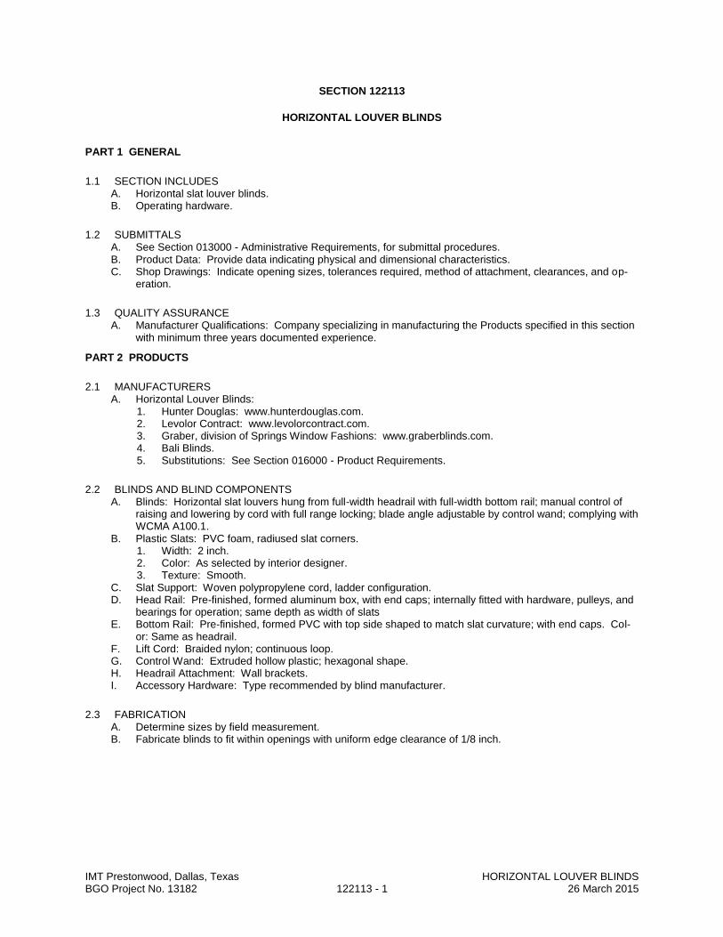
IMT Prestonwood, Dallas, Texas HORIZONTAL LOUVER BLINDS BGO Project No. 13182 122113 - 1 26 March 2015
SECTION 122113
HORIZONTAL LOUVER BLINDS
PART 1 GENERAL
1.1 SECTION INCLUDES A. Horizontal slat louver blinds. B. Operating hardware.
1.2 SUBMITTALS A. See Section 013000 - Administrative Requirements, for submittal procedures. B. Product Data: Provide data indicating physical and dimensional characteristics. C. Shop Drawings: Indicate opening sizes, tolerances required, method of attachment, clearances, and op-
eration.
1.3 QUALITY ASSURANCE A. Manufacturer Qualifications: Company specializing in manufacturing the Products specified in this section
with minimum three years documented experience.
PART 2 PRODUCTS
2.1 MANUFACTURERS A. Horizontal Louver Blinds:
1. Hunter Douglas: www.hunterdouglas.com. 2. Levolor Contract: www.levolorcontract.com. 3. Graber, division of Springs Window Fashions: www.graberblinds.com. 4. Bali Blinds. 5. Substitutions: See Section 016000 - Product Requirements.
2.2 BLINDS AND BLIND COMPONENTS A. Blinds: Horizontal slat louvers hung from full-width headrail with full-width bottom rail; manual control of
raising and lowering by cord with full range locking; blade angle adjustable by control wand; complying with WCMA A100.1.
B. Plastic Slats: PVC foam, radiused slat corners. 1. Width: 2 inch. 2. Color: As selected by interior designer. 3. Texture: Smooth.
C. Slat Support: Woven polypropylene cord, ladder configuration. D. Head Rail: Pre-finished, formed aluminum box, with end caps; internally fitted with hardware, pulleys, and
bearings for operation; same depth as width of slats E. Bottom Rail: Pre-finished, formed PVC with top side shaped to match slat curvature; with end caps. Col-
or: Same as headrail. F. Lift Cord: Braided nylon; continuous loop. G. Control Wand: Extruded hollow plastic; hexagonal shape. H. Headrail Attachment: Wall brackets. I. Accessory Hardware: Type recommended by blind manufacturer.
2.3 FABRICATION A. Determine sizes by field measurement. B. Fabricate blinds to fit within openings with uniform edge clearance of 1/8 inch.

IMT Prestonwood, Dallas, Texas HORIZONTAL LOUVER BLINDS BGO Project No. 13182 122113 - 2 26 March 2015
PART 3 EXECUTION
3.1 EXAMINATION A. Verify that openings are ready to receive the work. B. Ensure structural blocking and supports are correctly placed.
3.2 INSTALLATION A. Install blinds in accordance with manufacturer's instructions. B. Secure in place with flush countersunk fasteners.
3.3 INSTALLATION TOLERANCES A. Maximum Variation of Gap at Window Opening Perimeter: 1/4 inch.
3.4 ADJUSTING A. Adjust blinds for smooth operation.
3.5 CLEANING A. Clean blind surfaces just prior to occupancy.
END OF SECTION

IMT Prestonwood, Dallas, Texas RESIDENTIAL CASEWORK BGO Project No. 13182 123530 - 1 26 March 2015
SECTION 123530
RESIDENTIAL CASEWORK
PART 1 GENERAL
1.1 SECTION INCLUDES A. Kitchen cabinets. B. Vanity cabinets. C. Casework hardware.
1.2 REFERENCE STANDARDS A. ANSI/KCMA A161.1 - Performance and Construction Standard for Kitchen and Vanity Cabinets;
Kitchen Cabinet Manufacturers Association ; 2000 (R2006). B. KCMA (DIR) - Directory of Certified Cabinet Manufacturers; Kitchen Cabinet Manufacturers
Association ; current edition, online.
1.3 SUBMITTALS A. See Section 013000 - Administrative Requirements, for submittal procedures. B. Product Data: Provide component dimensions and construction details. C. Shop Drawings: Indicate casework locations, large scale plans, elevations, clearances required,
rough-in and anchor placement dimensions and tolerances . D. Samples: Submit two samples illustrating each color and finish.
1.4 QUALITY ASSURANCE A. Products: Complying with KCMA A161.1 and KCMA Certified. B. Manufacturer: Company specializing in manufacturing the type of products specified in this section,
with minimum three years of documented experience.
1.5 MOCK-UP A. Provide full size mock-up of casework base unit and upper cabinet. B. Locate where directed. C. Mock-up may remain as part of the Work.
PART 2 PRODUCTS
2.1 MANUFACTURERS A. Residential Casework:
1. Kraftmaid Cabinetry, Inc. 2. Wellborn Cabinet, Inc 3. Armstong. 4. Triangle Pacific. 5. Republic Cabinets. 6. Leedo Manufacturing. 7. Master Wood Craft. 8. Substitutions: See Section 016000 - Product Requirements.
2.2 COMPONENTS A. Cabinet Construction: Softwood lumber framing and particle board, tempered hardboard gables. B. Countertops: As specified in Section 123600. C. Door and Drawer Fronts: Solid wood. D. Bolts, Nuts, Washers and Screws: Of size and type to suit application. E. Concealed Joint Fasteners: Threaded steel. F. Acceptable Products: As selected by Architect.
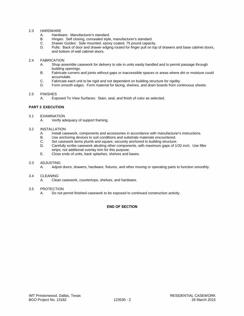
IMT Prestonwood, Dallas, Texas RESIDENTIAL CASEWORK BGO Project No. 13182 123530 - 2 26 March 2015
2.3 HARDWARE A. Hardware: Manufacturer's standard. B. Hinges: Self closing, concealed style, manufacturer's standard. C. Drawer Guides: Side mounted, epoxy coated, 75 pound capacity. D. Pulls: Back of door and drawer edging routed for finger pull on top of drawers and base cabinet doors,
and bottom of wall cabinet doors.
2.4 FABRICATION A. Shop assemble casework for delivery to site in units easily handled and to permit passage through
building openings. B. Fabricate corners and joints without gaps or inaccessible spaces or areas where dirt or moisture could
accumulate. C. Fabricate each unit to be rigid and not dependent on building structure for rigidity. D. Form smooth edges. Form material for facing, shelves, and drain boards from continuous sheets.
2.5 FINISHES A. Exposed To View Surfaces: Stain, seal, and finish of color as selected.
PART 3 EXECUTION
3.1 EXAMINATION A. Verify adequacy of support framing.
3.2 INSTALLATION A. Install casework, components and accessories in accordance with manufacturer's instructions. B. Use anchoring devices to suit conditions and substrate materials encountered. C. Set casework items plumb and square, securely anchored to building structure. D. Carefully scribe casework abutting other components, with maximum gaps of 1/32 inch. Use filler
strips; not additional overlay trim for this purpose. E. Close ends of units, back splashes, shelves and bases.
3.3 ADJUSTING A. Adjust doors, drawers, hardware, fixtures, and other moving or operating parts to function smoothly.
3.4 CLEANING A. Clean casework, countertops, shelves, and hardware.
3.5 PROTECTION A. Do not permit finished casework to be exposed to continued construction activity.
END OF SECTION
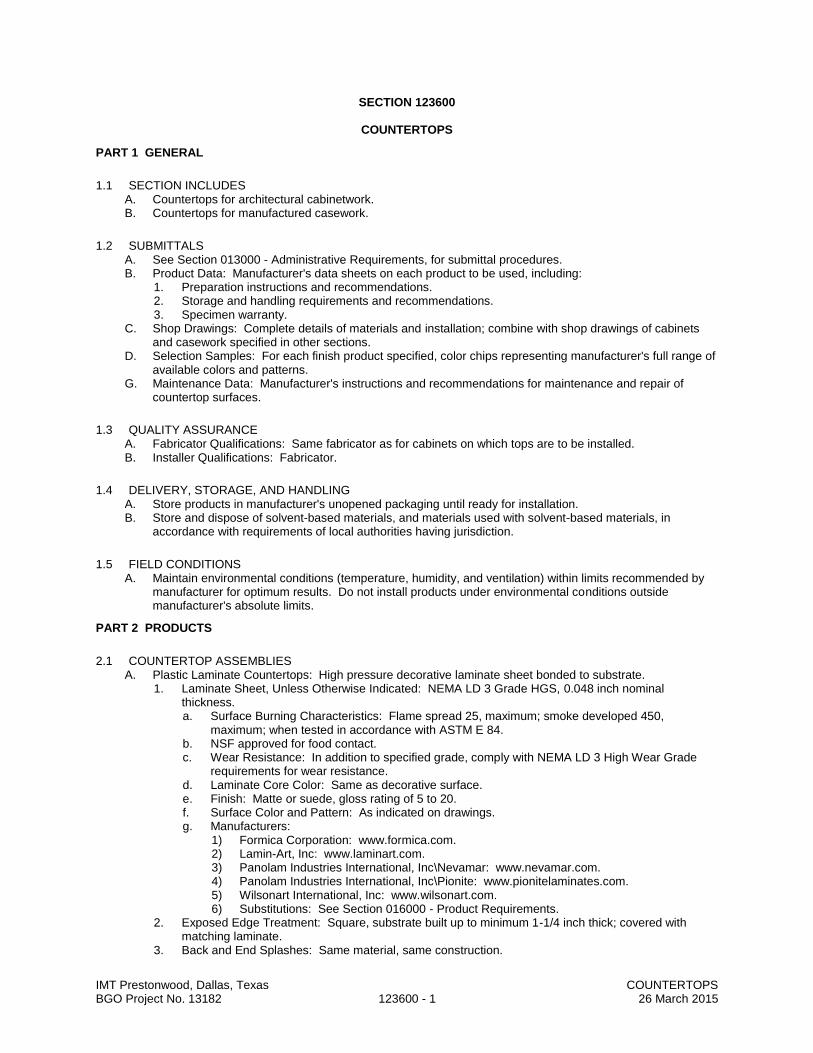
IMT Prestonwood, Dallas, Texas COUNTERTOPS BGO Project No. 13182 123600 - 1 26 March 2015
SECTION 123600
COUNTERTOPS
PART 1 GENERAL
1.1 SECTION INCLUDES A. Countertops for architectural cabinetwork. B. Countertops for manufactured casework.
1.2 SUBMITTALS A. See Section 013000 - Administrative Requirements, for submittal procedures. B. Product Data: Manufacturer's data sheets on each product to be used, including:
1. Preparation instructions and recommendations. 2. Storage and handling requirements and recommendations. 3. Specimen warranty.
C. Shop Drawings: Complete details of materials and installation; combine with shop drawings of cabinets and casework specified in other sections.
D. Selection Samples: For each finish product specified, color chips representing manufacturer's full range of available colors and patterns.
G. Maintenance Data: Manufacturer's instructions and recommendations for maintenance and repair of countertop surfaces.
1.3 QUALITY ASSURANCE A. Fabricator Qualifications: Same fabricator as for cabinets on which tops are to be installed. B. Installer Qualifications: Fabricator.
1.4 DELIVERY, STORAGE, AND HANDLING A. Store products in manufacturer's unopened packaging until ready for installation. B. Store and dispose of solvent-based materials, and materials used with solvent-based materials, in
accordance with requirements of local authorities having jurisdiction.
1.5 FIELD CONDITIONS A. Maintain environmental conditions (temperature, humidity, and ventilation) within limits recommended by
manufacturer for optimum results. Do not install products under environmental conditions outside manufacturer's absolute limits.
PART 2 PRODUCTS
2.1 COUNTERTOP ASSEMBLIES A. Plastic Laminate Countertops: High pressure decorative laminate sheet bonded to substrate.
1. Laminate Sheet, Unless Otherwise Indicated: NEMA LD 3 Grade HGS, 0.048 inch nominal thickness. a. Surface Burning Characteristics: Flame spread 25, maximum; smoke developed 450,
maximum; when tested in accordance with ASTM E 84. b. NSF approved for food contact. c. Wear Resistance: In addition to specified grade, comply with NEMA LD 3 High Wear Grade
requirements for wear resistance. d. Laminate Core Color: Same as decorative surface. e. Finish: Matte or suede, gloss rating of 5 to 20. f. Surface Color and Pattern: As indicated on drawings. g. Manufacturers:
1) Formica Corporation: www.formica.com. 2) Lamin-Art, Inc: www.laminart.com. 3) Panolam Industries International, Inc\Nevamar: www.nevamar.com. 4) Panolam Industries International, Inc\Pionite: www.pionitelaminates.com. 5) Wilsonart International, Inc: www.wilsonart.com. 6) Substitutions: See Section 016000 - Product Requirements.
2. Exposed Edge Treatment: Square, substrate built up to minimum 1-1/4 inch thick; covered with matching laminate.
3. Back and End Splashes: Same material, same construction.
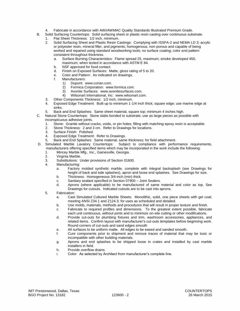
IMT Prestonwood, Dallas, Texas COUNTERTOPS BGO Project No. 13182 123600 - 2 26 March 2015
4. Fabricate in accordance with AWI/AWMAC Quality Standards Illustrated Premium Grade. B. Solid Surfacing Countertops: Solid surfacing sheet or plastic resin casting over continuous substrate.
1. Flat Sheet Thickness: 1/2 inch, minimum. 2. Solid Surfacing Sheet and Plastic Resin Castings: Complying with ISSFA-2 and NEMA LD 3; acrylic
or polyester resin, mineral filler, and pigments; homogenous, non-porous and capable of being worked and repaired using standard woodworking tools; no surface coating; color and pattern consistent throughout thickness. a. Surface Burning Characteristics: Flame spread 25, maximum; smoke developed 450,
maximum; when tested in accordance with ASTM E 84. b. NSF approved for food contact. d. Finish on Exposed Surfaces: Matte, gloss rating of 5 to 20. e. Color and Pattern: As indicated on drawings. f. Manufacturers:
1) Dupont: www.corian.com. 2) Formica Corporation: www.formica.com. 3) Avonite Surfaces: www.avonitesurfaces.com. 4) Wilsonart International, Inc: www.wilsonart.com.
3. Other Components Thickness: 1/2 inch, minimum. 4. Exposed Edge Treatment: Built up to minimum 1-1/4 inch thick; square edge; use marine edge at
sinks. 5. Back and End Splashes: Same sheet material, square top; minimum 4 inches high.
C. Natural Stone Countertops: Stone slabs bonded to substrate; use as large pieces as possible with inconspicuous adhesive joints. 1. Stone: Granite without cracks, voids, or pin holes; filling with matching epoxy resin is acceptable. 2. Stone Thickness: 2 and 3 cm. Refer to Drawings for locations. 3. Surface Finish: Polished. 4. Exposed Edge Treatment: Refer to Drawings. 5. Back and End Splashes: Same material, same thickness; for field attachment.
D. Simulated Marble Lavatory Countertops: Subject to compliance with performance requirements, manufacturers offering specified items which may be incorporated in the work include the following: 1. Mincey Marble Mfg., Inc., Gainesville, Georgia. 2. Virginia Marble. 3. Substitutions: Under provisions of Section 01600. 4. Manufacturing:
a. Factory molded synthetic marble, complete with integral backsplash (see Drawings for height of back and side splashes), apron and loose end splashes. See Drawings for size.
b. Thickness: Homogeneous 3/4-inch (min) thick. c. Sanitary sealant specified in Section 07900 – Joint Sealers. d. Aprons (where applicable) to be manufactured of same material and color as top. See
Drawings for cutouts. Indicated cutouts are to be cast into aprons. 5. Fabrication:
a. Cast Simulated Cultured Marble Sheets: Monolithic, solid, one piece sheets with gel coat; meeting ANSI Z34.1 and Z124.3; for uses as scheduled and detailed.
b. Use molds, materials, methods and procedures that will result in proper texture and finish. c. Fabricate to required profiles and dimensions. To the greatest extent possible, fabricate
each unit continuous, without joints and to minimize on-site cutting or other modifications. d. Provide cut-outs for plumbing fixtures and trim, washroom accessories, appliances, and
related items. Confirm layout with manufacturer's cut-outs templates before beginning work. Round corners of cut-outs and sand edges smooth
e. All surfaces to be uniform matte. All edges to be eased and sanded smooth. f. Cure components prior to shipment and remove traces of material that may be toxic or
incompatible with other building materials. g. Aprons and end splashes to be shipped loose in crates and installed by cast marble
installers in field. h. Provide overflow drains. i. Color: As selected by Architect from manufacturer’s complete line.

IMT Prestonwood, Dallas, Texas COUNTERTOPS BGO Project No. 13182 123600 - 3 26 March 2015
2.2 ACCESSORY MATERIALS A. Wood-Based Components: B. Plywood for Supporting Substrate (stone): PS 1 Exterior Grade, A-C veneer grade, minimum 5-ply;
minimum 3/4 inch thick; join lengths using metal splines. C. Particleboard for Supporting Substrate (plastic laminate and solid surfacing): ANSI A208.1 Grade 2-M-2,
45 pcf minimum density; minimum 3/4 inch thick; join lengths using metal splines. D. Adhesives: Chemical resistant waterproof adhesive as recommended by manufacturer of materials being
joined. E. Cove Molding for Top of Splashes: Rubber with semi-gloss finish and T-spline to fit between splash and
wall; 1/2 inch by 1/2 inch. F. Joint Sealant: Mildew-resistant silicone sealant, clear.
2.3 FABRICATION A. Fabricate tops and splashes in the largest sections practicable, with top surface of joints flush.
1. Join lengths of tops using best method recommended by manufacturer. 2. Fabricate to overhang fronts and ends of cabinets 1 inch except where top butts against cabinet or
wall. 3. Prepare all cutouts accurately to size; replace tops having improperly dimensioned or unnecessary
cutouts or fixture holes. B. Provide back/end splash wherever counter edge abuts vertical surface unless otherwise indicated.
1. Secure to countertop with concealed fasteners and with contact surfaces set in waterproof glue. 2. Height: 4 inches, unless otherwise indicated.
C. Solid Surfacing: Fabricate tops up to 144 inches long in one piece; join pieces with adhesive sealant in accordance with manufacturer's recommendations and instructions.
PART 3 EXECUTION
3.1 EXAMINATION A. Do not begin installation until substrates have been properly prepared. B. If substrate preparation is the responsibility of another installer, notify Architect of unsatisfactory
preparation before proceeding. C. Verify that wall surfaces have been finished and mechanical and electrical services and outlets are
installed in proper locations.
3.2 PREPARATION A. Clean surfaces thoroughly prior to installation. B. Prepare surfaces using the methods recommended by the manufacturer for achieving the best result for
the substrate under the project conditions.
3.3 INSTALLATION A. Securely attach countertops to cabinets using concealed fasteners. Make flat surfaces level; shim where
required. B. Attach plastic laminate countertops using screws with minimum penetration into substrate board of 5/8
inch. C. Seal joint between back/end splashes and vertical surfaces.
1. Where indicated use rubber cove molding. 2. Where applied cove molding is not indicated use specified sealant.
3.4 CLEANING A. Clean countertops surfaces thoroughly.
3.5 PROTECTION A. Protect installed products until completion of project. B. Touch-up, repair or replace damaged products before Substantial Completion.
END OF SECTION

IMT Prestonwood, Dallas, Texas ELECTRIC TRACTION ELEVATORS BGO Project No. 13182 142100 - 1 26 March 2015
SECTION 142100
ELECTRIC TRACTION ELEVATORS
PART 1 - GENERAL
1.1 RELATED DOCUMENTS A. Drawings and general provisions of the Contract, including General and Supplementary Conditions and
Division 01 Specification Sections, apply to this Section.
1.2 SUMMARY A. This Section includes machine room-less electric traction passenger elevators.
1.3 DEFINITIONS A. Definitions in ASME A17.1 apply to work of this Section. B. Defective Elevator Work: Operation or control system failure, including excessive malfunctions;
performances below specified ratings; excessive wear; unusual deterioration or aging of materials or finishes; unsafe conditions; need for excessive maintenance; abnormal noise or vibration; and similar unusual, unexpected, and unsatisfactory conditions.
1.4 SUBMITTALS A. Product Data: Include capacities, sizes, performances, operations, safety features, finishes, and similar
information. Include product data for the following: 1. Car enclosures and hoistway entrances. 2. Operation, control, and signal systems.
B. Shop Drawings: Show plans, elevations, sections, and large-scale details indicating service at each landing, machine room layout, coordination with building structure, relationships with other construction, and locations of equipment and signals. Include large-scale layout of car control station and standby power operation control panel. Indicate variations from specified requirements, maximum dynamic and static loads imposed on building structure at points of support, and maximum and average power demands.
C. Samples for Initial Selection: For finishes involving color selection. D. Manufacturer Certificates: Signed by elevator manufacturer certifying that hoistway, pit, and machine
room layout and dimensions, as shown on Drawings, and electrical service, as shown and specified, are adequate for elevator system being provided.
E. Operation and Maintenance Data: For elevators to include in emergency, operation, and maintenance manuals. 1. In addition to items specified in Division 01 Section "Operation and Maintenance Data," include
diagnostic and repair information available to manufacturer's and Installer's maintenance personnel.
F. Inspection and Acceptance Certificates and Operating Permits: As required by authorities having jurisdiction for normal, unrestricted elevator use.
G. Continuing Maintenance Proposal: Service agreement specified in this Section.
1.5 QUALITY ASSURANCE A. Installer Qualifications: Elevator manufacturer or manufacturer's authorized representative who is trained
and approved for installation of units required for this Project. B. Source Limitations: Obtain elevators, [including hydraulic passenger elevators specified in another
Division 14 Section], through one source from a single manufacturer. 1. Provide major elevator components, including driving machines, controllers, signal fixtures, door
operators, car frames, cabs, and entrances, manufactured by a single manufacturer. C. Regulatory Requirements: Comply with ASME A17.1. D. Accessibility Requirements: Comply with Section 4.10 in the U.S. Architectural & Transportation Barriers
Compliance Board's "Americans with Disabilities Act (ADA), Accessibility Guidelines for Buildings and Facilities (ADAAG)."
1.6 DELIVERY, STORAGE, AND HANDLING A. Deliver, store, and handle materials, components, and equipment in manufacturer's protective packaging. B. Store materials, components, and equipment off of ground, under cover, and in a dry location. Handle
according to manufacturer's written recommendations to prevent damage, deterioration, or soiling.

IMT Prestonwood, Dallas, Texas ELECTRIC TRACTION ELEVATORS BGO Project No. 13182 142100 - 2 26 March 2015
1.7 COORDINATION A. Coordinate installation of sleeves, block outs, elevator equipment with integral anchors, and other items
that are embedded in concrete or masonry for elevator equipment. Furnish templates, sleeves, elevator equipment with integral anchors, and installation instructions and deliver to Project site in time for installation.
B. Coordinate sequence of elevator installation with other work to avoid delaying the Work. C. Coordinate locations and dimensions of other work relating to electric traction elevators including pit
ladders, sumps, and floor drains in pits; entrance subsills; machine beams; and electrical service, electrical outlets, lights, and switches in pits and machine rooms.
1.8 WARRANTY A. Special Manufacturer's Warranty: Manufacturer's standard form in which manufacturer agrees to repair,
restore, or replace defective elevator work within specified warranty period. 1. Warranty Period: One year from date of Substantial Completion.
1.9 MAINTENANCE SERVICE A. Initial Maintenance Service: Beginning at Substantial Completion, provide one year's full maintenance
service by skilled employees of elevator Installer. Include monthly preventive maintenance, repair or replacement of worn or defective components, lubrication, cleaning, and adjusting as required for proper elevator operation at rated speed and capacity. Provide parts and supplies same as those used in the manufacture and installation of original equipment. 1. Perform maintenance, including emergency callback service, during normal working hours. 2. Include 24-hour-per-day, 7-day-per-week emergency callback service.
a. Response Time: Two hours or less. B. Continuing Maintenance Proposal: Provide a continuing maintenance proposal from Installer to Owner,
in the form of a standard one-year maintenance agreement, starting on date initial maintenance service is concluded. State services, obligations, conditions, and terms for agreement period and for future renewal options.
C. Continuing Maintenance Proposal: Provide a continuing maintenance proposal from Installer to Owner with terms, conditions, and obligations as set forth in, and in same form as, "Draft of Elevator Maintenance Agreement" at end of this Section, starting on date initial maintenance service is concluded.
PART 2 - PRODUCTS
2.1 MANUFACTURERS A. Available Manufacturers: Subject to compliance with requirements, manufacturers offering products that
may be incorporated into the Work include, but are not limited to, the following: B. Manufacturers: Subject to compliance with requirements, provide products by one of the following:
1. KONE Inc. (Ecospace is basis of design). 2. Otis Elevator Co. 3. Schindler Elevator Corp. 4. ThyssenKrupp Elevator.
2.2 SYSTEMS AND COMPONENTS A. General: Provide manufacturer's standard elevator systems. Where components are not otherwise
indicated, provide standard components published by manufacturer as included in standard pre-engineered elevator systems and as required for complete system.
B. Elevator Machines: At manufacturer's option, provide either variable-voltage, variable-frequency, ac-type or variable-voltage, dc-type hoisting machines. Provide solid-state power converters. 1. Limit total harmonic distortion of regenerated power to 5 percent per IEEE 519. 2. Provide means for absorbing regenerated power when elevator system is operating on standby
power. 3. Provide line filters or chokes to prevent electrical peaks or spikes from feeding back into building
power system. C. Fluid for Oil Buffers: If oil buffers are used, use only fire-resistant hydraulic fluid containing antioxidant,
anticorrosive, antifoaming, and metal-passivating additives. 1. Available Product: Subject to compliance with requirements, a product that may be incorporated
into the Work includes, but is not limited to, "Hydro Safe (FR)" by Hydro Safe Oil Division, Inc. D. Inserts: Furnish required concrete and masonry inserts and similar anchorage devices for installing guide
rails, machinery, and other components of elevator work where installation of devices is specified in another Section.
E. Machine Beams: Provide framing to support elevator hoisting machine and deflector sheaves from the building structure. Comply with Division 05 Section "Metal Fabrications" for materials and fabrication.

IMT Prestonwood, Dallas, Texas ELECTRIC TRACTION ELEVATORS BGO Project No. 13182 142100 - 3 26 March 2015
F. Car Frame and Platform: Welded steel units. G. Guides: Provide roller guides or polymer-coated, nonlubricated sliding guides at top and bottom of car
and counterweight frames.
2.3 OPERATION SYSTEMS A. General: Provide manufacturer's standard microprocessor operation system for each elevator for each
group of elevators as required to provide type of operation system indicated. B. Group Automatic Operation with Demand-Based Dispatching: Provide reprogrammable group automatic
system that assigns cars to hall calls based on a dispatching program designed to minimize passenger waiting time. System automatically adjusts to changes in demand for different traffic conditions including heavy incoming, heavy two-way, heavy outgoing, and light off-hours as variations of normal two-way traffic. 1. Available Products: Subject to compliance with requirements, products that may be incorporated
into the Work include, but are not limited to, the following: 2. Products: Subject to compliance with requirements, provide one of the following:
a. KONE Inc.; KCM 831. b. Otis Elevator Co.; Elevonic. c. Schindler Elevator Corp.; Miconic TX. d. ThyssenKrupp Elevator; Traflomatic.
C. Single-Car Auxiliary Operations: In addition to primary operation system features, provide the following operational features for elevators where indicated: 2. Battery-Powered Lowering: If power fails and car is at a floor, it remains at that floor, opens its
doors, and shuts down. If car is between floors, it is lowered to the next floor below, opens its doors, and shuts down. System includes rechargeable battery and automatic recharging system.
D. Group Auxiliary Operations: In addition to primary operation system features, provide the following operational features for elevators and elevator groups where indicated: 1. Battery-Powered Lowering: If power fails, cars that are at a floor remain at that floor, open their
doors, and shut down. Cars that are between floors are lowered one at a time to the next floor below, open their doors, and shut down. System includes rechargeable battery and automatic recharging system.
2. Independent Service: Keyswitch in car control station removes car from group operation and allows it to respond only to car calls. Key cannot be removed from keyswitch when car is in independent service. When in independent service, doors close only in response to door close button.
E. Security Features: Provide the following security features, where indicated. Security features shall not affect emergency firefighters' service. 1. Card-Reader Operation: System uses card readers at car control stations to authorize calls.
Security system determines which landings and at what times calls require authorization by card reader. Provide required conductors in traveling cable and panel in machine room for interconnecting card readers, other security access system equipment, and elevator controllers. Provide stripe-swipe card reader integral with each car control station. a. Security access system equipment is specified in Division 28 Section "Access Control." b. Security access system equipment is not in the Contract.
2. Keyswitch Operation: Push buttons are activated and deactivated by security keyswitches at car control stations. Key is removable only in deactivated position.
3. Car-to-Lobby Feature: Feature, activated by keyswitch at main lobby, that causes car all cars in a group to return immediately to lobby and open doors for inspection. On deactivation by keyswitch, calls registered before keyswitch activation are completed and normal operation is resumed.
2.4 DOOR REOPENING DEVICES A. Infrared Array: Provide door reopening devices with uniform array of 36 or more microprocessor-
controlled, infrared light beams projecting across car entrance. Interruption of one or more of the light beams shall cause doors to stop and reopen.
B. Nudging Feature: After car doors are prevented from closing for predetermined adjustable time, through activating door reopening device, a loud buzzer shall sound and doors shall begin to close at reduced kinetic energy.
2.5 FINISH MATERIALS A. General: Provide the following materials for exposed parts of elevator car enclosures, car doors,
hoistway entrance doors and frames, and signal equipment as indicated. B. Stainless-Steel Bars: ASTM A 276, Type 304. C. Stainless-Steel Tubing: ASTM A 554, Grade MT 304. D. Aluminum Extrusions: ASTM B 221, Alloy 6063. E. Nickel Silver Extrusions: ASTM B 151/B 151M, Alloy UNS No. C74500 or No. C77600.
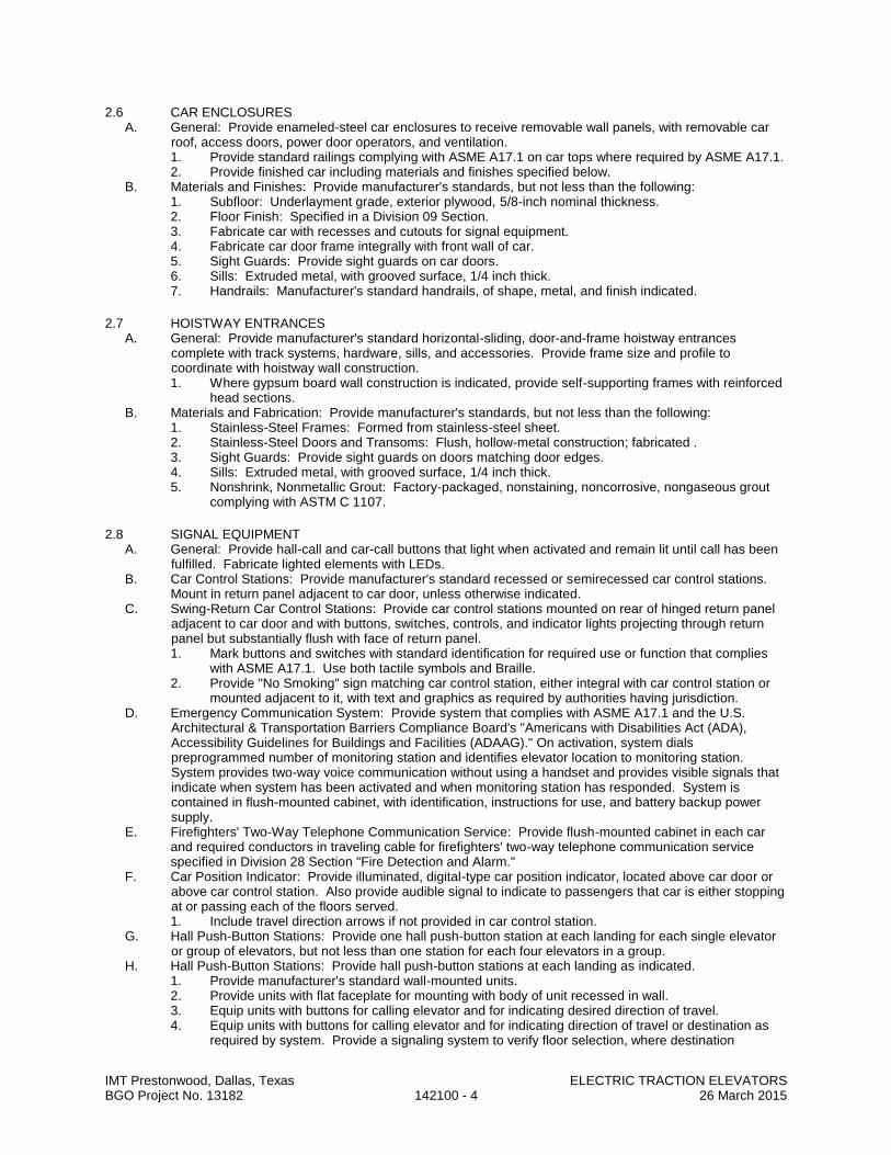
IMT Prestonwood, Dallas, Texas ELECTRIC TRACTION ELEVATORS BGO Project No. 13182 142100 - 4 26 March 2015
2.6 CAR ENCLOSURES A. General: Provide enameled-steel car enclosures to receive removable wall panels, with removable car
roof, access doors, power door operators, and ventilation. 1. Provide standard railings complying with ASME A17.1 on car tops where required by ASME A17.1. 2. Provide finished car including materials and finishes specified below.
B. Materials and Finishes: Provide manufacturer's standards, but not less than the following: 1. Subfloor: Underlayment grade, exterior plywood, 5/8-inch nominal thickness. 2. Floor Finish: Specified in a Division 09 Section. 3. Fabricate car with recesses and cutouts for signal equipment. 4. Fabricate car door frame integrally with front wall of car. 5. Sight Guards: Provide sight guards on car doors. 6. Sills: Extruded metal, with grooved surface, 1/4 inch thick. 7. Handrails: Manufacturer's standard handrails, of shape, metal, and finish indicated.
2.7 HOISTWAY ENTRANCES A. General: Provide manufacturer's standard horizontal-sliding, door-and-frame hoistway entrances
complete with track systems, hardware, sills, and accessories. Provide frame size and profile to coordinate with hoistway wall construction. 1. Where gypsum board wall construction is indicated, provide self-supporting frames with reinforced
head sections. B. Materials and Fabrication: Provide manufacturer's standards, but not less than the following:
1. Stainless-Steel Frames: Formed from stainless-steel sheet. 2. Stainless-Steel Doors and Transoms: Flush, hollow-metal construction; fabricated . 3. Sight Guards: Provide sight guards on doors matching door edges. 4. Sills: Extruded metal, with grooved surface, 1/4 inch thick. 5. Nonshrink, Nonmetallic Grout: Factory-packaged, nonstaining, noncorrosive, nongaseous grout
complying with ASTM C 1107.
2.8 SIGNAL EQUIPMENT A. General: Provide hall-call and car-call buttons that light when activated and remain lit until call has been
fulfilled. Fabricate lighted elements with LEDs. B. Car Control Stations: Provide manufacturer's standard recessed or semirecessed car control stations.
Mount in return panel adjacent to car door, unless otherwise indicated. C. Swing-Return Car Control Stations: Provide car control stations mounted on rear of hinged return panel
adjacent to car door and with buttons, switches, controls, and indicator lights projecting through return panel but substantially flush with face of return panel. 1. Mark buttons and switches with standard identification for required use or function that complies
with ASME A17.1. Use both tactile symbols and Braille. 2. Provide "No Smoking" sign matching car control station, either integral with car control station or
mounted adjacent to it, with text and graphics as required by authorities having jurisdiction. D. Emergency Communication System: Provide system that complies with ASME A17.1 and the U.S.
Architectural & Transportation Barriers Compliance Board's "Americans with Disabilities Act (ADA), Accessibility Guidelines for Buildings and Facilities (ADAAG)." On activation, system dials preprogrammed number of monitoring station and identifies elevator location to monitoring station. System provides two-way voice communication without using a handset and provides visible signals that indicate when system has been activated and when monitoring station has responded. System is contained in flush-mounted cabinet, with identification, instructions for use, and battery backup power supply.
E. Firefighters' Two-Way Telephone Communication Service: Provide flush-mounted cabinet in each car and required conductors in traveling cable for firefighters' two-way telephone communication service specified in Division 28 Section "Fire Detection and Alarm."
F. Car Position Indicator: Provide illuminated, digital-type car position indicator, located above car door or above car control station. Also provide audible signal to indicate to passengers that car is either stopping at or passing each of the floors served. 1. Include travel direction arrows if not provided in car control station.
G. Hall Push-Button Stations: Provide one hall push-button station at each landing for each single elevator or group of elevators, but not less than one station for each four elevators in a group.
H. Hall Push-Button Stations: Provide hall push-button stations at each landing as indicated. 1. Provide manufacturer's standard wall-mounted units. 2. Provide units with flat faceplate for mounting with body of unit recessed in wall. 3. Equip units with buttons for calling elevator and for indicating desired direction of travel. 4. Equip units with buttons for calling elevator and for indicating direction of travel or destination as
required by system. Provide a signaling system to verify floor selection, where destination

IMT Prestonwood, Dallas, Texas ELECTRIC TRACTION ELEVATORS BGO Project No. 13182 142100 - 5 26 March 2015
registration is required, and to direct passengers to appropriate car. a. Provide a means for passengers to indicate that they have disabilities so control system can
allow extra room in assigned car. b. Provide for connecting units that require destination registration to building security access
system so a card reader can be used to register calls. 5. Provide telephone jack in each unit for firefighters' two-way telephone communication service
specified in Division 28 Section "Fire Detection and Alarm." I. Hall Lanterns: Units with illuminated arrows; but provide single arrow at terminal landings.
1. Manufacturer's standard wall-mounted units, for mounting above entrance frames. J. Hall Annunciator: With each hall lantern, provide audible signals indicating car arrival and direction of
travel. Signals sound once for up and twice for down. 1. At manufacturer's option, audible signals may be placed on each car.
K. Hall Position Indicators: Provide illuminated, digital-display-type position indicators, located above each hoistway entrance at ground floor. Provide units with flat faceplate for mounting with body of unit recessed in wall. 1. Integrate ground-floor hall lanterns with hall position indicators.
M. Fire Command Center Annunciator Panel: Provide panel containing illuminated position indicators for each elevator, clearly labeled with elevator designation; include illuminated signal that indicates when elevator is operational and when it is at the designated emergency return level with doors open. Provide standby power elevator selector switch(es), as required by ASME A17.1, adjacent to position indicators. Provide illuminated signal that indicates when normal power supply has failed.
N. Corridor Call Station Pictograph Signs: Provide signs matching hall push-button stations, with text and graphics as required by authorities having jurisdiction, indicating that in case of fire elevators are out of service and exits should be used instead. Provide one sign at each hall push-button station, unless otherwise indicated.
2.9 ELEVATORS A. Elevator Description:
1. Type: Geared traction. 2. Machine Location: Hoistway; no machine room is provided. 3. Rated Load: 4000 lbs. 6. Rated Speed: 200 fpm. 7. Operation System: Selective collective automatic operation. 8. Auxiliary Operations:
d. Independent service. 9. Security Features: Card-reader operation Keyswitch operation. 10. Dual Car Control Stations: Provide two car control stations in each elevator; equip only one with
required keyswitches if any. 11. Car Enclosures:
a. Inside Height: 120 inches to underside of ceiling. d. Front Walls (Return Panels): Satin stainless steel, No. 4 brushed finish. e. Car Fixtures: Satin stainless steel, No. 4 finish. f. Side and Rear Wall Panels: Refer to Finish Legend. g. Reveals: Satin stainless steel, No. 4 finish. h. Door Faces (Interior): Satin stainless steel, No. 4 finish. i. Door Sills: Aluminum, mill finish. j. Ceiling: Refer to Finish Legend. k. Handrails: 1-1/2 inches round satin stainless steel, No. 4 finish, at sides of car. l. Floor Finish: Refer to Finish Legend.
12. Hoistway Entrances: As follows: a. Width: 42 inches. b. Height: 96 inches or as otherwise indicated on Drawings. c. Type: Single-speed side slide. d. Frames: No. 4 finish satin stainless steel. e. Doors: No. 4 finish satin stainless steel. f. Sills: Aluminum, mill finish.
13. Hall Fixtures: Satin stainless steel, No. 4 finish. 14. Additional Requirements:
a. Provide inspection certificate in each car, mounted under acrylic cover with frame made from satin stainless steel, No. 4 finish.
b. Provide blanket hooks in all cars and one complete set(s) of full-height protective blankets. c. Provide battery powered lowering. d. Provide model DL-20 telephone system with 7 inch display.

IMT Prestonwood, Dallas, Texas ELECTRIC TRACTION ELEVATORS BGO Project No. 13182 142100 - 6 26 March 2015
PART 3 - EXECUTION
3.1 EXAMINATION A. Examine elevator areas, with Installer present, for compliance with requirements for installation
tolerances and other conditions affecting performance. Examine hoistways, hoistway openings, pits, and machine rooms as constructed; verify critical dimensions; and examine supporting structure and other conditions under which elevator work is to be installed. 1. For the record, prepare a written report, endorsed by Installer, listing dimensional discrepancies
and conditions detrimental to performance or indicating that dimensions and conditions were found to be satisfactory.
4. Proceed with installation only after unsatisfactory conditions have been corrected.
3.2 INSTALLATION A. Comply with manufacturer's written instructions. B. Welded Construction: Provide welded connections for installing elevator work where bolted connections
are not required for subsequent removal or for normal operation, adjustment, inspection, maintenance, and replacement of worn parts. Comply with AWS standards for workmanship and for qualifications of welding operators.
C. Sound Isolation: Mount rotating and vibrating equipment on vibration-isolating mounts designed to minimize transmission of vibrations to structure and thereby minimize structure-borne noise from elevator system.
D. Lubricate operating parts of systems, including ropes, as recommended by manufacturers. E. Alignment: Coordinate installation of hoistway entrances with installation of elevator guide rails for
accurate alignment of entrances with car. Where possible, delay final adjustment of sills and doors unti l car is operable in shaft. Reduce clearances to minimum, safe, workable dimension at each landing.
F. Leveling Tolerance: 1/8 inch, up or down, regardless of load and direction of travel. G. Set sills flush with finished floor surface at landing. Fill space under sill solidly with nonshrink,
nonmetallic grout. H. Locate hall signal equipment for elevators as follows, unless otherwise indicated:
1. For groups of elevators, locate hall push-button stations between two elevators at center of group or at location most convenient for approaching passengers.
2. Place hall lanterns either above or beside each hoistway entrance. 3. Mount hall lanterns at a minimum of 72 inches above finished floor.
3.3 FIELD QUALITY CONTROL A. Acceptance Testing: On completion of elevator installation and before permitting use (either temporary
or permanent) of elevators, perform acceptance tests as required and recommended by ASME A17.1 and by governing regulations and agencies.
B. Operating Test: Load each elevator one elevator of each type, capacity, speed, and travel distance to rated capacity and operate continuously for 30 minutes over full travel distance, stopping at each level and proceeding immediately to the next. Record temperature rise of elevator machine during 30-minute test period. Record failure to perform as required.
C. Advise Owner, Architect, and authorities having jurisdiction in advance of dates and times tests are to be performed on elevators.
3.4 PROTECTION A. Temporary Use: Limit temporary use for construction purposes to one elevator. Comply with the
following requirements for each elevator used for construction purposes: 1. Provide car with temporary enclosure, either within finished car or in place of finished car, to
protect finishes from damage. 2. Provide strippable protective film on entrance and car doors and frames. 3. Provide padded wood bumpers on entrance door frames covering jambs and frame faces. 4. Provide other protective coverings, barriers, devices, signs, and procedures as needed to protect
elevator and elevator equipment. 5. Do not load elevators beyond their rated weight capacity. 6. Engage elevator Installer to provide full maintenance service. Include preventive maintenance,
repair or replacement of worn or defective components, lubrication, cleaning, and adjusting as necessary for proper elevator operation at rated speed and capacity. Provide parts and supplies same as those used in the manufacture and installation of original equipment.
7. Engage elevator Installer to restore damaged work, if any, so no evidence remains of correction. Return items that cannot be refinished in the field to the shop, make required repairs and refinish entire unit, or provide new units as required.

IMT Prestonwood, Dallas, Texas ELECTRIC TRACTION ELEVATORS BGO Project No. 13182 142100 - 7 26 March 2015
3.5 DEMONSTRATION A. Engage a factory-authorized service representative to train Owner's maintenance personnel to operate,
adjust, and maintain elevator(s). Refer to Division 01 Section "Demonstration and Training." B. Check operation of each elevator with Owner's personnel present and before date of Substantial
Completion. Determine that operation systems and devices are functioning properly. C. Check operation of each elevator with Owner's personnel present not more than one month before end of
warranty period. Determine that operation systems and devices are functioning properly.
END OF SECTION
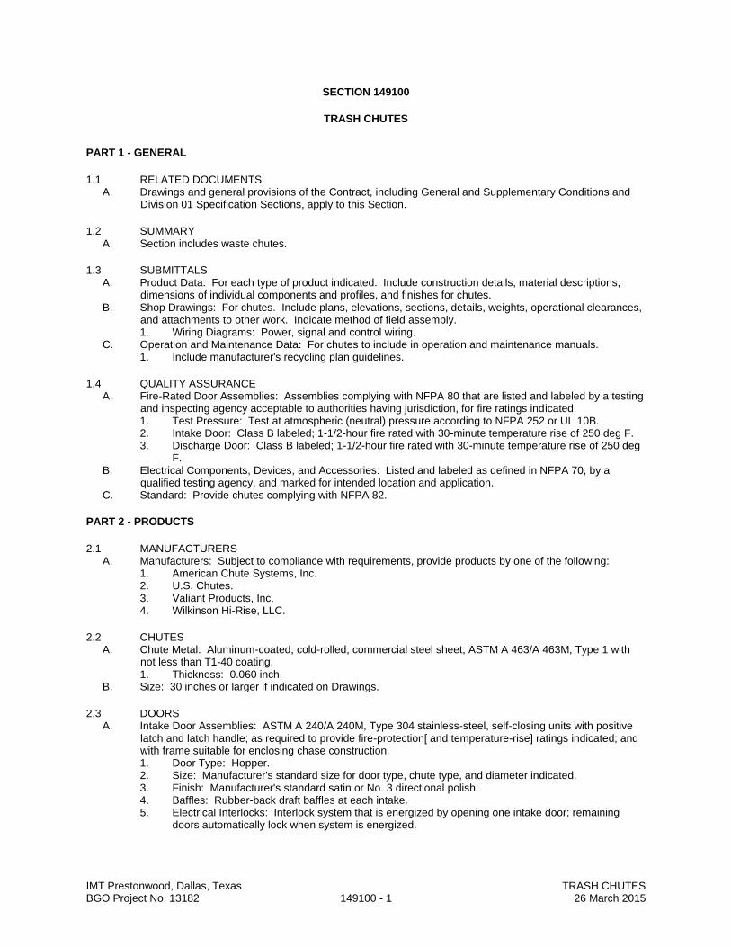
IMT Prestonwood, Dallas, Texas TRASH CHUTES BGO Project No. 13182 149100 - 1 26 March 2015
SECTION 149100
TRASH CHUTES
PART 1 - GENERAL
1.1 RELATED DOCUMENTS A. Drawings and general provisions of the Contract, including General and Supplementary Conditions and
Division 01 Specification Sections, apply to this Section.
1.2 SUMMARY A. Section includes waste chutes.
1.3 SUBMITTALS A. Product Data: For each type of product indicated. Include construction details, material descriptions,
dimensions of individual components and profiles, and finishes for chutes. B. Shop Drawings: For chutes. Include plans, elevations, sections, details, weights, operational clearances,
and attachments to other work. Indicate method of field assembly. 1. Wiring Diagrams: Power, signal and control wiring.
C. Operation and Maintenance Data: For chutes to include in operation and maintenance manuals. 1. Include manufacturer's recycling plan guidelines.
1.4 QUALITY ASSURANCE A. Fire-Rated Door Assemblies: Assemblies complying with NFPA 80 that are listed and labeled by a testing
and inspecting agency acceptable to authorities having jurisdiction, for fire ratings indicated. 1. Test Pressure: Test at atmospheric (neutral) pressure according to NFPA 252 or UL 10B. 2. Intake Door: Class B labeled; 1-1/2-hour fire rated with 30-minute temperature rise of 250 deg F. 3. Discharge Door: Class B labeled; 1-1/2-hour fire rated with 30-minute temperature rise of 250 deg
F. B. Electrical Components, Devices, and Accessories: Listed and labeled as defined in NFPA 70, by a
qualified testing agency, and marked for intended location and application. C. Standard: Provide chutes complying with NFPA 82.
PART 2 - PRODUCTS
2.1 MANUFACTURERS A. Manufacturers: Subject to compliance with requirements, provide products by one of the following:
1. American Chute Systems, Inc. 2. U.S. Chutes. 3. Valiant Products, Inc. 4. Wilkinson Hi-Rise, LLC.
2.2 CHUTES A. Chute Metal: Aluminum-coated, cold-rolled, commercial steel sheet; ASTM A 463/A 463M, Type 1 with
not less than T1-40 coating. 1. Thickness: 0.060 inch.
B. Size: 30 inches or larger if indicated on Drawings.
2.3 DOORS A. Intake Door Assemblies: ASTM A 240/A 240M, Type 304 stainless-steel, self-closing units with positive
latch and latch handle; as required to provide fire-protection[ and temperature-rise] ratings indicated; and with frame suitable for enclosing chase construction. 1. Door Type: Hopper. 2. Size: Manufacturer's standard size for door type, chute type, and diameter indicated. 3. Finish: Manufacturer's standard satin or No. 3 directional polish. 4. Baffles: Rubber-back draft baffles at each intake. 5. Electrical Interlocks: Interlock system that is energized by opening one intake door; remaining
doors automatically lock when system is energized.
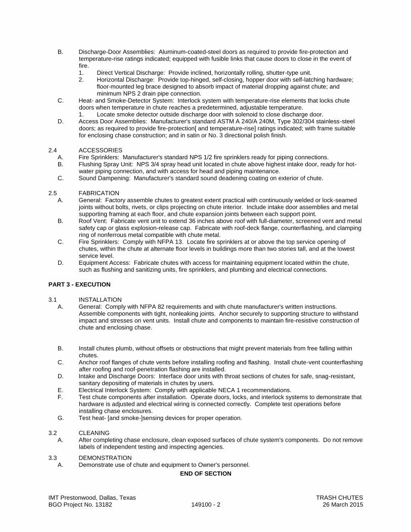
IMT Prestonwood, Dallas, Texas TRASH CHUTES BGO Project No. 13182 149100 - 2 26 March 2015
B. Discharge-Door Assemblies: Aluminum-coated-steel doors as required to provide fire-protection and temperature-rise ratings indicated; equipped with fusible links that cause doors to close in the event of fire. 1. Direct Vertical Discharge: Provide inclined, horizontally rolling, shutter-type unit. 2. Horizontal Discharge: Provide top-hinged, self-closing, hopper door with self-latching hardware;
floor-mounted leg brace designed to absorb impact of material dropping against chute; and minimum NPS 2 drain pipe connection.
C. Heat- and Smoke-Detector System: Interlock system with temperature-rise elements that locks chute doors when temperature in chute reaches a predetermined, adjustable temperature. 1. Locate smoke detector outside discharge door with solenoid to close discharge door.
D. Access Door Assemblies: Manufacturer's standard ASTM A 240/A 240M, Type 302/304 stainless-steel doors; as required to provide fire-protection[ and temperature-rise] ratings indicated; with frame suitable for enclosing chase construction; and in satin or No. 3 directional polish finish.
2.4 ACCESSORIES A. Fire Sprinklers: Manufacturer's standard NPS 1/2 fire sprinklers ready for piping connections. B. Flushing Spray Unit: NPS 3/4 spray head unit located in chute above highest intake door, ready for hot-
water piping connection, and with access for head and piping maintenance. C. Sound Dampening: Manufacturer's standard sound deadening coating on exterior of chute.
2.5 FABRICATION A. General: Factory assemble chutes to greatest extent practical with continuously welded or lock-seamed
joints without bolts, rivets, or clips projecting on chute interior. Include intake door assemblies and metal supporting framing at each floor, and chute expansion joints between each support point.
B. Roof Vent: Fabricate vent unit to extend 36 inches above roof with full-diameter, screened vent and metal safety cap or glass explosion-release cap. Fabricate with roof-deck flange, counterflashing, and clamping ring of nonferrous metal compatible with chute metal.
C. Fire Sprinklers: Comply with NFPA 13. Locate fire sprinklers at or above the top service opening of chutes, within the chute at alternate floor levels in buildings more than two stories tall, and at the lowest service level.
D. Equipment Access: Fabricate chutes with access for maintaining equipment located within the chute, such as flushing and sanitizing units, fire sprinklers, and plumbing and electrical connections.
PART 3 - EXECUTION
3.1 INSTALLATION A. General: Comply with NFPA 82 requirements and with chute manufacturer's written instructions.
Assemble components with tight, nonleaking joints. Anchor securely to supporting structure to withstand impact and stresses on vent units. Install chute and components to maintain fire-resistive construction of chute and enclosing chase.
B. Install chutes plumb, without offsets or obstructions that might prevent materials from free falling within
chutes. C. Anchor roof flanges of chute vents before installing roofing and flashing. Install chute-vent counterflashing
after roofing and roof-penetration flashing are installed. D. Intake and Discharge Doors: Interface door units with throat sections of chutes for safe, snag-resistant,
sanitary depositing of materials in chutes by users. E. Electrical Interlock System: Comply with applicable NECA 1 recommendations. F. Test chute components after installation. Operate doors, locks, and interlock systems to demonstrate that
hardware is adjusted and electrical wiring is connected correctly. Complete test operations before installing chase enclosures.
G. Test heat- [and smoke-]sensing devices for proper operation.
3.2 CLEANING A. After completing chase enclosure, clean exposed surfaces of chute system's components. Do not remove
labels of independent testing and inspecting agencies.
3.3 DEMONSTRATION A. Demonstrate use of chute and equipment to Owner's personnel.
END OF SECTION
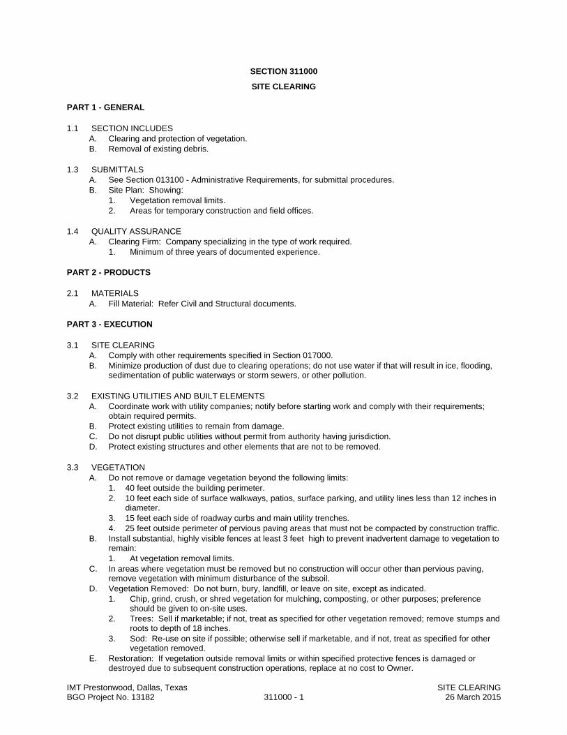
IMT Prestonwood, Dallas, Texas SITE CLEARING BGO Project No. 13182 311000 - 1 26 March 2015
SECTION 311000
SITE CLEARING
PART 1 - GENERAL
1.1 SECTION INCLUDES
A. Clearing and protection of vegetation.
B. Removal of existing debris.
1.3 SUBMITTALS
A. See Section 013100 - Administrative Requirements, for submittal procedures.
B. Site Plan: Showing:
1. Vegetation removal limits.
2. Areas for temporary construction and field offices.
1.4 QUALITY ASSURANCE
A. Clearing Firm: Company specializing in the type of work required.
1. Minimum of three years of documented experience.
PART 2 - PRODUCTS
2.1 MATERIALS
A. Fill Material: Refer Civil and Structural documents.
PART 3 - EXECUTION
3.1 SITE CLEARING
A. Comply with other requirements specified in Section 017000.
B. Minimize production of dust due to clearing operations; do not use water if that will result in ice, flooding, sedimentation of public waterways or storm sewers, or other pollution.
3.2 EXISTING UTILITIES AND BUILT ELEMENTS
A. Coordinate work with utility companies; notify before starting work and comply with their requirements; obtain required permits.
B. Protect existing utilities to remain from damage.
C. Do not disrupt public utilities without permit from authority having jurisdiction.
D. Protect existing structures and other elements that are not to be removed.
3.3 VEGETATION
A. Do not remove or damage vegetation beyond the following limits:
1. 40 feet outside the building perimeter.
2. 10 feet each side of surface walkways, patios, surface parking, and utility lines less than 12 inches in diameter.
3. 15 feet each side of roadway curbs and main utility trenches.
4. 25 feet outside perimeter of pervious paving areas that must not be compacted by construction traffic.
B. Install substantial, highly visible fences at least 3 feet high to prevent inadvertent damage to vegetation to remain:
1. At vegetation removal limits.
C. In areas where vegetation must be removed but no construction will occur other than pervious paving, remove vegetation with minimum disturbance of the subsoil.
D. Vegetation Removed: Do not burn, bury, landfill, or leave on site, except as indicated.
1. Chip, grind, crush, or shred vegetation for mulching, composting, or other purposes; preference should be given to on-site uses.
2. Trees: Sell if marketable; if not, treat as specified for other vegetation removed; remove stumps and roots to depth of 18 inches.
3. Sod: Re-use on site if possible; otherwise sell if marketable, and if not, treat as specified for other vegetation removed.
E. Restoration: If vegetation outside removal limits or within specified protective fences is damaged or destroyed due to subsequent construction operations, replace at no cost to Owner.

IMT Prestonwood, Dallas, Texas SITE CLEARING BGO Project No. 13182 311000 - 2 26 March 2015
3.4 DEBRIS
A. Remove debris, junk, and trash from site.
B. Leave site in clean condition, ready for subsequent work.
C. Clean up spillage and wind-blown debris from public and private lands.
END OF SECTION
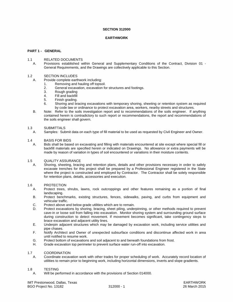
IMT Prestonwood, Dallas, Texas EARTHWORK BGO Project No. 13182 312000 - 1 26 March 2015
SECTION 312000
EARTHWORK
PART 1 - GENERAL
1.1 RELATED DOCUMENTS A. Provisions established within General and Supplementary Conditions of the Contract, Division 01 -
General Requirements, and the Drawings are collectively applicable to this Section.
1.2 SECTION INCLUDES A. Provide complete earthwork including:
1. Removing and hauling off topsoil. 2. General excavation, excavation for structures and footings. 3. Rough grading 4. Fill and backfill 5. Finish grading. 6. Shoring and bracing excavations with temporary shoring, sheeting or retention system as required
by code law or ordinance to protect excavation area, workers, nearby streets and structures. B. Note: Refer to the soils investigation report and to recommendations of the soils engineer. If anything
contained herein is contradictory to such report or recommendations, the report and recommendations of the soils engineer shall govern.
1.3 SUBMITTALS A. Samples: Submit data on each type of fill material to be used as requested by Civil Engineer and Owner.
1.4 BASIS FOR BIDS A. Bids shall be based on excavating and filling with materials encountered at site except where special fill or
backfill materials are specified herein or indicated on Drawings. No allowance or extra payments will be made by reason of variation in types of soil encountered or variations in their moisture contents.
1.5 QUALITY ASSURANCE A. Shoring, sheeting, bracing and retention plans, details and other provisions necessary in order to safely
excavate trenches for this project shall be prepared by a Professional Engineer registered in the State where the project is constructed and employed by Contractor. The Contractor shall be solely responsible for retention plans, details, accessories and execution.
1.6 PROTECTION A. Protect trees, shrubs, lawns, rock outcroppings and other features remaining as a portion of final
landscaping. B. Protect benchmarks, existing structures, fences, sidewalks, paving, and curbs from equipment and
vehicular traffic. C. Protect above and below grade utilities which are to remain. D. Protect excavations by shoring, bracing, sheet piling, underpinning, or other methods required to prevent
cave-in or loose soil from falling into excavation. Monitor shoring system and surrounding ground surface during construction to detect movement. If movement becomes significant, take contingency steps to brace excavation and adjacent utility lines.
E. Underpin adjacent structures which may be damaged by excavation work, including service utilities and pipe chases.
F. Notify Architect and Owner of unexpected subsurface conditions and discontinue affected work in area until notified to resume work.
G. Protect bottom of excavations and soil adjacent to and beneath foundations from frost. H. Grade excavation top perimeter to prevent surface water run-off into excavation.
1.7 COORDINATION A. Coordinate excavation work with other trades for proper scheduling of work. Accurately record location of
utilities to remain prior to beginning work, including horizontal dimensions, inverts and slope gradients.
1.8 TESTING A. Will be performed in accordance with the provisions of Section 014000.
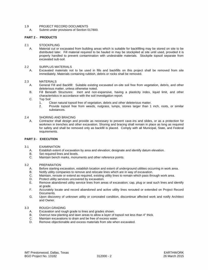
IMT Prestonwood, Dallas, Texas EARTHWORK BGO Project No. 13182 312000 - 2 26 March 2015
1.9 PROJECT RECORD DOCUMENTS A. Submit under provisions of Section 017800.
PART 2 - PRODUCTS
2.1 STOCKPILING A. Material cut or excavated from building areas which is suitable for backfilling may be stored on site to be
distributed later. Fill material required to be hauled in may be stockpiled at site until used, provided it is properly handled to prevent contamination with undesirable materials. Stockpile topsoil separate from excavated sub-soil.
2.2 SURPLUS MATERIALS A. Excavated materials not to be used in fills and backfills on this project shall be removed from site
immediately. Materials containing rubbish, debris or rocks shall be removed.
2.3 MATERIALS A. General Fill and Backfill: Suitable existing excavated on-site soil free from vegetation, debris, and other
deleterious matter, unless otherwise noted. B. Fill Beneath Structures: Inert and non-expansive, having a plasticity index, liquid limit, and other
characteristics in accordance with the soil investigation report. C. Top Soil
1. Clean natural topsoil free of vegetation, debris and other deleterious matter. 2. Provide topsoil free from weeds, nutgrass, lumps, stones larger than 1 inch, roots, or similar
substances.
2.4 SHORING AND BRACING A. Contractor shall design and provide as necessary to prevent cave-ins and slides, or as a protection for
workmen in trenches and other excavation. Shoring and bracing shall remain in place as long as required for safety and shall be removed only as backfill is placed. Comply with all Municipal, State, and Federal requirements.
PART 3 - EXECUTION
3.1 EXAMINATION A. Establish extent of excavation by area and elevation; designate and identify datum elevation. B. Set required lines and levels. C. Maintain bench marks, monuments and other reference points.
3.2 PREPARATION A. Before starting excavation, establish location and extent of underground utilities occurring in work area. B. Notify utility companies to remove and relocate lines which are in way of excavation. C. Maintain, reroute or extend as required, existing utility lines to remain which pass through work area. D. Protect utility services uncovered by excavation. E. Remove abandoned utility service lines from areas of excavation; cap, plug or seal such lines and identify
at grade. F. Accurately locate and record abandoned and active utility lines rerouted or extended on Project Record
Documents. G. Upon discovery of unknown utility or concealed condition, discontinue affected work and notify Architect
and Owner.
3.3 ROUGH GRADING A. Excavation and rough grade to lines and grades shown. B. Overcut new planting and lawn areas to allow a layer of topsoil not less than 4" thick. C. Maintain excavations to drain and be free of excess water. D. Remove objectionable and excess materials from site when excavated.

IMT Prestonwood, Dallas, Texas EARTHWORK BGO Project No. 13182 312000 - 3 26 March 2015
3.4 STRUCTURAL EXCAVATION A. Locate and mark all existing underground utilities and services before beginning structural excavation. B. Provide excavation for structures and footings, as required for construction, bracing and removal of forms,
applying waterproofing, and to permit inspection. C. Machine slope banks to angle of repose or less until shored. Excavation shall not interfere with normal 45
degree angle bearing splay of any foundation. D. Bottom of excavating shall be reasonably level. E. Maintain excavations in as near their natural moisture conditions as possible. F. Fill over-excavated areas under structure bearing surfaces in accordance with Soil Engineer's direction. G. Do not allow construction equipment to create "pumping" of soils. H. Stockpile excavated clean fill for reuse where directed. Remove excess or unsuitable excavated fill from
site. I. Remove boulders or cobbles. Use of explosives will not be permitted. J. Coordinate with drilled pier work for special requirements and arrangements regarding excavation to rough
out elevations. K. If presence of perched water is encountered, provide interior drainage.
3.5 EXCAVATION BENEATH FLOOR SLABS A. Beneath Floor Slab on Grade: Refer to recommendations of the soils engineer.
3.6 FILLS AND BACKFILLS - GENERAL A. Verify areas to be backfilled are free of debris, snow, ice or water, and ground surfaces are not frozen. B. Proofroll exposed subgrade in building and paving areas to detect unsuitable soil conditions. Commence
proofrolling operations after a suitable period of dry weather to avoid degrading acceptable subgrade surfaces. Make four passes over each section with proofrolling equipment, with the last two perpendicular to the first two.
C. Cut out soft areas of subgrade not readily capable of in- situ compaction. Backfill and compact to density equal to requirements for subsequent backfill material.
D. Site backfill systematically, as early as possible, to allow maximum time for natural settlement. Do not backfill over porous, wet or spongy subgrade surfaces.
E. Use a placement method that will not disturb or damage utilities in trenches. F. Maintain optimum moisture content of backfill materials to attain required compaction density. G. Make gradual changes in grade. Blend slopes into level areas. H. Refer to soils investigation report for additional requirements.
3.7 FILLS (WITHIN STRUCTURE) A. Select Fill Beneath Slabs on Grade: (refer to soils report for specific fill placement criteria)
1. Scarify exposed sub-grade and recompact to an appropriate density determined using Standard Proctor Compaction Test, at moisture content as indicated in soil report.
2. Place appropriate fill in loose lifts and compact each lift to an appropriate density determined using Standard Proctor Compaction Test, at moisture content as indicated in soil report.
3. Place select fill to a minimum depth indicated on drawings. 4. Prevent excessive loss of moisture during construction.
B. Refer to soils investigation report for additional requirements.
3.8 FILLS (OUTSIDE STRUCTURE) A. Roughen and loosen filled areas before placing of fill materials. B. Spread suitable fill materials in uniform layers over area not to exceed 8" thick compaction. C. Wet and work materials as required for proper compaction and thoroughly mix. Compaction shall be by
tamping rollers or by utilizing excavation equipment to spread and compact fill to a uniform density equal to natural density of material before excavating.
D. Areas adjacent to building, or where compacting equipment cannot work, shall be compacted with hand tampers.
E. Scarify upper 6 inches of exposed sub-grade and compact filled areas to density as indicated in the soils report, to lines and grades shown, with allowances for a final layer of topsoil at least 4 inches thick in lawn and planter areas.
F. Plant Beds: Refer to landscape drawings Beds shall be prepared to a minimum of 4 inches of depth.

IMT Prestonwood, Dallas, Texas EARTHWORK BGO Project No. 13182 312000 - 4 26 March 2015
3.9 BACKFILL (OUTSIDE STRUCTURE) A. Ensure areas to be backfilled are free from debris, snow, ice and water and that ground surfaces are note
in frozen condition. B. Do not backfill over existing subgrade surfaces which are porous, wet or spongy. C. Backfill areas to grades, contours, levels and elevations indicated. D. Backfill systematically and as early as possible to allow maximum time for natural settlement and
compaction. E. After permanent construction is in place, forms and trash removed, sub-soil drainage and water-proofing
complete and inspections complete, backfill with approved materials and compact to approximate density of natural ground.
F. Place backfill in layers not exceeding 8" loose depth, and hand or machine tamp to compaction required. G. Water may be added to backfill material as an aid to compaction; however, material shall not be wet to
form a mud or paste.
3.10 REMOVAL OF CONTAMINATED SOIL A. Prior to finish grading: Soil contaminated with lime should be removed from lawn and plant bed areas.
Replace with clean, approved topsoil.
3.11 FINISH GRADING A. After rough grading has been completed and site cleared of construction debris, cover areas disturbed by
construction or graded to provide new finish grades with a layer of topsoil not less than 4" thick. B. Reuse stockpiled topsoil, cleaned of foreign matter, or provide additional approved topsoil as required. C. Final grades shall be as shown or as directed by Landscape Architect and shall slope away from building
and shall provide drainage for area. D. Degree of finish shall be that ordinarily obtainable with blade grader or scraper operations. E. Finish surfaces shall be not be more than 0.10 feet above or below established grade elevation. F. Provide uniform roundings at top and bottom of slopes and other breaks in grade. Correct irregularities
and areas where water will stand. G. Uniformly distribute topsoil to required grades; feather back to where grades remain unchanged. H. Finish lawn and unpaved areas to 1" below top of walk and curbs.
3.12 PROTECTION, CLEAN-UP AND EXCESS MATERIALS A. Protect grades from construction and weather damage, washing, erosion and rutting, and repair such
damage that occurs. B. Correct any settlement below established grades to prevent ponding of water. C. At locations where lime, concrete or other foreign matter has penetrated or been mixed with earth, remove
damaged earth and replace with clean material. D. Remove excess stockpiled material, debris, waste, and other material from site and leave work in clean
finished condition for final acceptance. Contractor is responsible for disposal of debris and excess materials.
3.13 QUALITY CONTROL A. Paving Subgrade Stabilization: Perform one subgrade in-place density test per 7,500 S.F. of subgrade,
after subgrade preparation is complete at locations determined by the soils engineer, in accordance with ASTM D2922 and ASTM D3017. Perform tests within 48 hours of placement of pavement construction.
B. Building Subgrade Stabilization: Make necessary soil tests (Atterberg Limit Series and ASTM D698 Standard Proctor for each type of fill specified) to determine the moisture content and density of existing subgrade and inspect and test the placement of additional fill lifts to verify that all fill materials used are in accordance with the specifications for that use. Perform one field density test (ASTM D2922) for each 5,000 S.F. of area within the building footprint on each lift prior to placement of additional fill material.
END OF SECTION

SECTION 31 63 29 DRILLED PIERS
IMT Prestonwood, Dallas, Texas DRILLED PIERS BGO Project No. 13182 31 63 29 - 1 26 March 2015
PART 1 GENERAL 1.1 SUMMARY
A. Section Includes: 1. Furnish all labor, materials, services and equipment as required in
conjunction with or properly incidental to drilling of piers as described herein and/or as shown on the Drawings.
B. Related Documents:
1. Drawings and general provisions of Contract, including General and Supplementary Conditions and Division 1, General Requirements, apply to Work of this section.
C. Related Sections:
1. Section 03 20 00 – Concrete Reinforcement. 2. Section 03 30 00 – Cast-in-Place Concrete. 3. Geotechnical Investigation Report: Furnished by Owner.
1.2 REFERENCES
A. American Concrete Institute (ACI). 1. ACI 301, Specifications for Structural Concrete for Buildings. 2. ACI 304R, Guide for Measuring, Mixing, Transporting and Placing Concrete. 3. ACI 305R, Hot Weather Concreting. 4. ACI 306R, Cold Weather Concreting. 5. ACI 311, ACI Manual of Concrete Inspection. 6. ACI 309, Standard Practice for Consolidation of Concrete. 7. ACI 311, ACI Manual of Concrete Inspection. 8. ACI 318, Building Code Requirements for Structural Concrete. 9. ACI 336.1, Standard Specification for the Construction of End Bearing Drilled
Piers. 1.3 SUBMITTALS
A. Reinforcement: Refer to Section 03 20 00. B. Concrete: Refer to Section 03 30 00.
1.4 MEASUREMENT AND PAYMENT
A. The Contract sum shall include all labor, materials, overhead and profit for completing drilled piers including removal of spoil. Cost of providing and placing of casings is to be included in base Contract. If casings are not required, cost of providing, installing, and removing same will be deducted from the Contract based on unit prices specified in other sections. Top of bearing stratum shown on Contract Drawings is for estimating purposes only. Pier drilling log prepared by the Testing Laboratory shall be used to adjust the Contract amount for greater and lesser pier depths, based on the actual top of bearing stratum elevation, or greater depths due to presence of sand pockets or clay seams encountered during the drilling process. Payment will not be made for pier penetrations into bearing stratum greater than that required by the Contract Documents, unless approved by Owner and Architect.
PART 2 PRODUCTS 2.1 MATERIALS
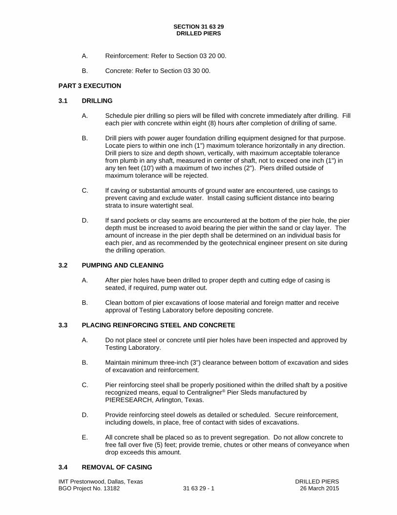
SECTION 31 63 29 DRILLED PIERS
IMT Prestonwood, Dallas, Texas DRILLED PIERS BGO Project No. 13182 31 63 29 - 1 26 March 2015
A. Reinforcement: Refer to Section 03 20 00.
B. Concrete: Refer to Section 03 30 00.
PART 3 EXECUTION 3.1 DRILLING
A. Schedule pier drilling so piers will be filled with concrete immediately after drilling. Fill each pier with concrete within eight (8) hours after completion of drilling of same.
B. Drill piers with power auger foundation drilling equipment designed for that purpose.
Locate piers to within one inch (1") maximum tolerance horizontally in any direction. Drill piers to size and depth shown, vertically, with maximum acceptable tolerance from plumb in any shaft, measured in center of shaft, not to exceed one inch (1") in any ten feet (10') with a maximum of two inches (2"). Piers drilled outside of maximum tolerance will be rejected.
C. If caving or substantial amounts of ground water are encountered, use casings to
prevent caving and exclude water. Install casing sufficient distance into bearing strata to insure watertight seal.
D. If sand pockets or clay seams are encountered at the bottom of the pier hole, the pier
depth must be increased to avoid bearing the pier within the sand or clay layer. The amount of increase in the pier depth shall be determined on an individual basis for each pier, and as recommended by the geotechnical engineer present on site during the drilling operation.
3.2 PUMPING AND CLEANING
A. After pier holes have been drilled to proper depth and cutting edge of casing is seated, if required, pump water out.
B. Clean bottom of pier excavations of loose material and foreign matter and receive
approval of Testing Laboratory before depositing concrete. 3.3 PLACING REINFORCING STEEL AND CONCRETE
A. Do not place steel or concrete until pier holes have been inspected and approved by Testing Laboratory.
B. Maintain minimum three-inch (3") clearance between bottom of excavation and sides
of excavation and reinforcement. C. Pier reinforcing steel shall be properly positioned within the drilled shaft by a positive
recognized means, equal to Centraligner® Pier Sleds manufactured by PIERESEARCH, Arlington, Texas.
D. Provide reinforcing steel dowels as detailed or scheduled. Secure reinforcement,
including dowels, in place, free of contact with sides of excavations.
E. All concrete shall be placed so as to prevent segregation. Do not allow concrete to free fall over five (5) feet; provide tremie, chutes or other means of conveyance when drop exceeds this amount.
3.4 REMOVAL OF CASING

SECTION 31 63 29 DRILLED PIERS
IMT Prestonwood, Dallas, Texas DRILLED PIERS BGO Project No. 13182 31 63 29 - 1 26 March 2015
A. Prior to breaking seal between temporary casing and underlying strata, static head of
plastic concrete shall be sufficiently above ground water and caving soils from entering hole during removal of casing. Once seal has been broken, temporary casing may be slowly removed in a vertical direction (no rotation permitted) while additional concrete is placed to top of pier.
3.5 IMPROPER INSTALLATION
A. The Contractor shall pay the cost of any and all changes due to improper installation of drilled piers. This shall include Architect’s and Engineer’s additional services made necessary by such failure, as well as costs for labor and materials.
3.6 FIELD QUALITY CONTROL AND TESTING
A. Soils Testing Laboratory shall make continuous inspections of pier drilling operations to determine that proper bearing stratum is obtained and utilized for bearing and that shafts are properly clean and dry before placing concrete.
B. Furnish complete pier log, showing pier number, date, weather conditions, ground
elevation, the diameter, top and bottom elevations of each pier, casing required or not required, actual penetration into bearing stratum, elevation of top of bearing stratum, concrete truck, ticket number, water added at job site, slump, reinforcement and any and all observed irregularities, deficiencies or deviations from the Contract Documents.
C. Pier drilling shall be scheduled such that the concrete can be placed immediately
after inspection.
END OF SECTION
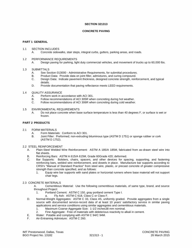
IMT Prestonwood, Dallas, Texas CONCRETE PAVING BGO Project No. 13182 321313 - 1 26 March 2015
SECTION 321313
CONCRETE PAVING
PART 1 GENERAL
1.1 SECTION INCLUDES A. Concrete sidewalks, stair steps, integral curbs, gutters, parking areas, and roads.
1.2 PERFORMANCE REQUIREMENTS A. Design paving for parking, light duty commercial vehicles, and movement of trucks up to 60,000 lbs.
1.3 SUBMITTALS A. See Section 013000 - Administrative Requirements, for submittal procedures. B. Product Data: Provide data on joint filler, admixtures, and curing compound. C. Design Data: Indicate pavement thickness, designed concrete strength, reinforcement, and typical
details. D. Provide documentation that paving reflectance meets LEED requirements.
1.4 QUALITY ASSURANCE A. Perform work in accordance with ACI 301. B. Follow recommendations of ACI 305R when concreting during hot weather. C. Follow recommendations of ACI 306R when concreting during cold weather.
1.5 ENVIRONMENTAL REQUIREMENTS A. Do not place concrete when base surface temperature is less than 40 degrees F, or surface is wet or
frozen.
PART 2 PRODUCTS
2.1 FORM MATERIALS A. Form Materials: Conform to ACI 301. B. Joint Filler: Preformed; non-extruding bituminous type (ASTM D 1751) or sponge rubber or cork
(ASTM D 1752).
2.2 STEEL REINFORCEMENT A. Plain-Steel Welded Wire Reinforcement: ASTM A 185/A 185M, fabricated from as-drawn steel wire into
flat sheets. B. Reinforcing Bars: ASTM A 615/A 615M, Grade 60Grade 420; deformed. C. Bar Supports: Bolsters, chairs, spacers, and other devices for spacing, supporting, and fastening
reinforcing bars, welded wire reinforcement, and dowels in place. Manufacture bar supports according to CRSI's "Manual of Standard Practice" from steel wire, plastic, or precast concrete of greater compressive strength than concrete specified, and as follows: 1. Equip wire bar supports with sand plates or horizontal runners where base material will not support
chair legs.
2.3 CONCRETE MATERIALS A. Cementitious Material: Use the following cementitious materials, of same type, brand, and source throughout Project:
1. Portland Cement: ASTM C 150, gray portland cement Type I. a. Fly Ash: ASTM C 618, Class C or Class F.
D. Normal-Weight Aggregates: ASTM C 33, Class 4S, uniformly graded. Provide aggregates from a single source with documented service-record data of at least 10 years' satisfactory service in similar paving applications and service conditions using similar aggregates and cementitious materials. 1. Maximum Coarse-Aggregate Size: 1-1/2 inches38 mm nominal. 2. Fine Aggregate: Free of materials with deleterious reactivity to alkali in cement.
E. Water: Potable and complying with ASTM C 94/C 94M. F. Air-Entraining Admixture: ASTM C 260.

IMT Prestonwood, Dallas, Texas CONCRETE PAVING BGO Project No. 13182 321313 - 2 26 March 2015
G. Chemical Admixtures: Admixtures certified by manufacturer to be compatible with other admixtures and to contain not more than 0.1 percent water-soluble chloride ions by mass of cementitious material. 1. Water-Reducing Admixture: ASTM C 494/C 494M, Type A. 2. High-Range, Water-Reducing Admixture: ASTM C 494/C 494M, Type F.
2.2 ACCESSORIES A. Curing Compound: ASTM C 309, Type 1, Class A. B. Joint Sealer: Type U-TB as specified in Section 079005. C. Pigmented Mineral Dry-Shake Hardener (at HC ramps): Factory-packaged, dry combination of
portland cement, graded quartz aggregate, color pigments, and plasticizing admixture. Use color pigments that are finely ground, non-fading mineral oxides inter-ground with cement.
1. Products: Subject to compliance with requirements, provide one of the following: a. Dayton Superior Corporation; Quartz Tuff. b. L&M Construction Chemicals, Inc.; QUARTZPLATE FF. c. Scofield, L. M. Company; LITHOCHROME Color Hardener.
Color: As selected by Architect from manufacturer's full range.
2.3 CONCRETE MIX DESIGN A. Proportioning Normal Weight Concrete: Comply with ACI 211.1 recommendations. B. Concrete Strength: Establish required average strength for each type of concrete on the basis of field
experience or trial mixtures, as specified in ACI 301. 1. For trial mixtures method, employ independent testing agency acceptable to Architect for
preparing and reporting proposed mix designs. C. Admixtures: Add acceptable admixtures as recommended in ACI 211.1 and at rates recommended by
manufacturer. D. Concrete Properties:
1. Compressive Strength, when tested in accordance with ASTM C 39/C 39M at 28 days: 3,000 lbs for sidewalks; Refer to civil engineering drawings for vehicular pavement strengths.
2. Fly Ash Content: Maximum 25 percent of cementitious materials by weight. 3. Calcined Pozzolan Content: Maximum 10 percent of cementitious materials by weight. 4. Water-Cement Ratio: Maximum 40 percent by weight. 5. Total Air Content: 4 percent, determined in accordance with ASTM C 173/C 173M. 6. Maximum Slump: 4 inches.
2.4 MIXING A. Transit Mixers: Comply with ASTM C 94/C 94M.
PART 3 EXECUTION
3.1 EXAMINATION A. Verify compacted subgrade is acceptable and ready to support paving and imposed loads. B. Verify gradients and elevations of base are correct.
3.2 PREPARATION A. Moisten base to minimize absorption of water from fresh concrete. B. Coat surfaces of manhole frames with oil to prevent bond with concrete pavement. C. Notify Architect minimum 24 hours prior to commencement of concreting operations.
3.3 FORMING A. Place and secure forms to correct location, dimension, profile, and gradient. B. Assemble formwork to permit easy stripping and dismantling without damaging concrete. C. Place joint filler vertical in position, in straight lines. Secure to formwork during concrete placement.
3.4 REINFORCEMENT A. Place reinforcement at top of slabs-on-grade. B. Interrupt reinforcement at contraction joints. C. Place dowels to achieve pavement and curb alignment as detailed.
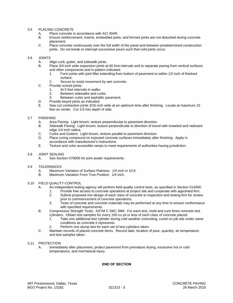
IMT Prestonwood, Dallas, Texas CONCRETE PAVING BGO Project No. 13182 321313 - 3 26 March 2015
3.5 PLACING CONCRETE A. Place concrete in accordance with ACI 304R. B. Ensure reinforcement, inserts, embedded parts, and formed joints are not disturbed during concrete
placement. C. Place concrete continuously over the full width of the panel and between predetermined construction
joints. Do not break or interrupt successive pours such that cold joints occur.
3.6 JOINTS A. Align curb, gutter, and sidewalk joints. B. Place 3/4 inch wide expansion joints at 60 foot intervals and to separate paving from vertical surfaces
and other components and in pattern indicated. 1. Form joints with joint filler extending from bottom of pavement to within 1/2 inch of finished
surface. 2. Secure to resist movement by wet concrete.
C. Provide scored joints: 1. At 5 feet intervals in walks. 2. Between sidewalks and curbs. 3. Between curbs and asphaltic pavement.
D. Provide keyed joints as indicated. E. Saw cut contraction joints 3/16 inch wide at an optimum time after finishing. Locate at maximum 15
feet on center. Cut 1/3 into depth of slab.
3.7 FINISHING A. Area Paving: Light broom, texture perpendicular to pavement direction. B. Sidewalk Paving: Light broom, texture perpendicular to direction of travel with troweled and radiused
edge 1/4 inch radius. C. Curbs and Gutters: Light broom, texture parallel to pavement direction. D. Place curing compound on exposed concrete surfaces immediately after finishing. Apply in
accordance with manufacturer's instructions. E. Texture and color accessible ramps to meet requirements of authorities having jurisdiction.
3.8 JOINT SEALING A. See Section 079005 for joint sealer requirements.
3.9 TOLERANCES A. Maximum Variation of Surface Flatness: 1/4 inch in 10 ft. B. Maximum Variation From True Position: 1/4 inch.
3.10 FIELD QUALITY CONTROL A. An independent testing agency will perform field quality control tests, as specified in Section 014000.
1. Provide free access to concrete operations at project site and cooperate with appointed firm. 2. Submit proposed mix design of each class of concrete to inspection and testing firm for review
prior to commencement of concrete operations. 3. Tests of concrete and concrete materials may be performed at any time to ensure conformance
with specified requirements. B. Compressive Strength Tests: ASTM C 39/C 39M. For each test, mold and cure three concrete test
cylinders. Obtain test samples for every 100 cu yd or less of each class of concrete placed. 1. Take one additional test cylinder during cold weather concreting, cured on job site under same
conditions as concrete it represents. 2. Perform one slump test for each set of test cylinders taken.
C. Maintain records of placed concrete items. Record date, location of pour, quantity, air temperature, and test samples taken.
3.11 PROTECTION A. Immediately after placement, protect pavement from premature drying, excessive hot or cold
temperatures, and mechanical injury.
END OF SECTION

IMT Prestonwood, Dallas, Texas DECORATIVE CONCRETE PAVING BGO Project No. 13182 321316 - 1 26 March 2015
SECTION 321316
DECORATIVE CONCRETE PAVING
PART 1 - GENERAL
1.1 RELATED DOCUMENTS A. Drawings and general provisions of the Contract, including General and Supplementary Conditions and
Division 01 Specification Sections, apply to this Section.
1.2 SUMMARY A. Section includes colored stamped and stained concrete paving.
1.3 DEFINITIONS A. Cementitious Materials: Portland cement alone or in combination with one or more of blended hydraulic
cement, fly ash and other pozzolans, and ground granulated blast-furnace slag.
1.4 SUBMITTALS A. Product Data: For each type of product indicated. B. Samples for Initial Selection: For each type of product, ingredient, or admixture requiring color, pattern, or
texture selection. C. Samples for Verification: For each type of exposed color, pattern, or texture indicated. D. Other Action Submittals:
1. Design Mixtures: For each decorative concrete paving mixture. Include alternate design mixtures when characteristics of materials, Project conditions, weather, test results, or other circumstances warrant adjustments.
E. Provide documentation that paving reflectance meets LEED requirements.
1.5 QUALITY ASSURANCE A. Installer Qualifications: An employer of workers trained and approved by manufacturer of decorative
concrete paving systems. B. Ready-Mix-Concrete Manufacturer Qualifications: A firm experienced in manufacturing ready-mixed
concrete products and that complies with ASTM C 94 requirements for production facilities and equipment. 1. Manufacturer certified according to NRMCA's "Certification of Ready Mixed Concrete Production
Facilities" (Quality Control Manual - Section 3, "Plant Certification Checklist"). C. Testing Agency Qualifications: Qualified according to ASTM C 1077 and ASTM E 329 for testing
indicated. 1. Personnel conducting field tests shall be qualified as ACI Concrete Field Testing Technician, Grade
1, according to ACI CP-1 or an equivalent certification program. D. Source Limitations: Obtain decorative concrete paving products and each type or class of cementitious
material of the same brand from same manufacturer's plant, and obtain each aggregate from single source.
E. Concrete Testing Service: Engage a qualified testing agency to perform material evaluation tests and to design concrete mixtures.
F. ACI Publications: Comply with ACI 301 unless otherwise indicated. G. Mockups: Build mockups to verify selections made under sample submittals and to demonstrate aesthetic
effects and set quality standards for materials and execution. 1. Build mockups of full-thickness sections of decorative concrete paving to demonstrate typical joints;
surface color, pattern, and texture; curing; and standard of workmanship. 2. Build mockups of decorative concrete paving in the location and of the size indicated or, if not
indicated, build mockups where directed by Architect and not less than 96 inches by 96 inches. 3. Approval of mockups does not constitute approval of deviations from the Contract Documents
contained in mockups unless Architect specifically approves such deviations in writing.
1.6 PROJECT CONDITIONS A. Traffic Control: Maintain access for vehicular and pedestrian traffic as required for other construction
activities.

IMT Prestonwood, Dallas, Texas DECORATIVE CONCRETE PAVING BGO Project No. 13182 321316 - 2 26 March 2015
PART 2 - PRODUCTS
2.1 FORMS A. Form Materials: Plywood, metal, metal-framed plywood, or other approved panel-type materials to provide
full-depth, continuous, straight, and smooth exposed surfaces. 1. Use flexible or uniformly curved forms for curves of a radius of 100 feet or less.
B. Forms for Textured Finish Concrete: Units of face design, size, arrangement, and configuration indicated. Provide solid backing and form supports to ensure stability of textured form liners.
C. Form-Release Agent: Commercially formulated form-release agent that will not bond with, stain, or adversely affect concrete surfaces and that will not impair subsequent treatments of concrete surfaces.
2.2 STEEL REINFORCEMENT A. Recycled Content: Provide steel reinforcement with an average recycled content of steel so postconsumer
recycled content plus one-half of preconsumer recycled content is not less than 25 percent. B. Reinforcing Bars: ASTM A 615, Grade 60; deformed. C. Plain-Steel Wire: ASTM A 82, as drawn. D. Joint Dowel Bars: ASTM A 615, Grade 60 plain-steel bars. Cut bars true to length, with ends square and
free of burrs. E. Bar Supports: Bolsters, chairs, spacers, and other devices for spacing, supporting, and fastening
reinforcing bars, welded wire reinforcement, and dowels in place. Manufacture bar supports according to CRSI's "Manual of Standard Practice" from steel wire, plastic, or precast concrete of greater compressive strength than concrete specified, and as follows: 1. Equip wire bar supports with sand plates or horizontal runners where base material will not support
chair legs.
2.3 CONCRETE MATERIALS A. Cementitious Material: Use the following cementitious materials, of the same type, brand, and source,
throughout Project: 1. Portland Cement: ASTM C 150, gray portland cement Type I.
a. Fly Ash: ASTM C 618, Class C or F. B. Normal-Weight Aggregates: ASTM C 33, Class 4S, uniformly graded. Provide aggregates from a single
source with documented service-record data of at least 10 years' satisfactory service in similar paving applications and service conditions using similar aggregates and cementitious materials. 1. Maximum Aggregate Size: 1 inch nominal. 2. Fine Aggregate: Free of materials with deleterious reactivity to alkali in cement.
C. Water: Potable and complying with ASTM C 94. D. Air-Entraining Admixture: ASTM C 260. E. Chemical Admixtures: Admixtures certified by manufacturer to be compatible with other admixtures and to
contain not more than 0.1 percent water-soluble chloride ions by mass of cementitious material. 1. Water-Reducing Admixture: ASTM C 494, Type A, colored.
F. Color Pigment: ASTM C 979, synthetic mineral-oxide pigments or colored water-reducing admixtures; color stable, free of carbon black, non-fading, and resistant to lime and other alkalis. 1. Manufacturers: Subject to compliance with requirements, provide products by one of the following:
a. Davis Colors. b. QC Construction Products. c. Scofield, L. M. Company. d. Solomon Colors, Inc.
2.4 SURFACE COLORING MATERIALS A. Pigmented Mineral Dry-Shake Hardener: Factory-packaged, dry combination of portland cement, graded
quartz aggregate, color pigments, and plasticizing admixture. Use color pigments that are finely ground, non-fading mineral oxides interground with cement. 1. Products: Subject to compliance with requirements, provide one of the following:
a. Dayton Superior Corporation; Quartz Tuff. b. Euclid Chemical Company (The), an RPM company; Surflex. c. L&M Construction Chemicals, Inc.; QUARTZPLATE FF. d. QC Construction Products; QC Color Hardener. e. Scofield, L. M. Company; LITHOCHROME Color Hardener.
B. Pigmented Powder Release Agent: Factory-packaged, dry combination of surface-conditioning and dispersing agents interground with color pigments that facilitates release of stamp mats. Use color pigments that are finely ground, nonfading mineral oxides interground with cement. 1. Products: Subject to compliance with requirements, provide one of the following:

IMT Prestonwood, Dallas, Texas DECORATIVE CONCRETE PAVING BGO Project No. 13182 321316 - 3 26 March 2015
a. Bomanite Corporation; Release Agent. b. QC Construction Products; QC Release Powder I . c. Scofield, L. M. Company; LITHOCHROME Antiquing Release.
2.5 STAMPING DEVICES A. Stamp Mats: Semirigid polyurethane mats with projecting textured and ridged underside capable of
imprinting texture and joint patterns on plastic concrete. 1. Manufacturers: Subject to compliance with requirements, provide products by one of the following:
a. Bomanite Corporation. b. Brickform. c. Butterfield Color. d. Scofield, L. M. Company.
B. Stamp Tools: Open-grid, aluminum or rigid-plastic stamp tool capable of imprinting joint patterns on plastic concrete. 1. Manufacturers: Subject to compliance with requirements, provide products by one of the following:
a. Matcrete Precision Stamped Concrete Tools. b. Scofield, L. M. Company. c. SuperStone, Inc.
2.6 CURING AND SEALING MATERIALS A. Curing Paper: Non-staining, waterproof paper, consisting of two layers of kraft paper cemented together
and reinforced with fiber, and complying with ASTM C 171. B. Waterborne, Membrane-Forming Curing Compound: ASTM C 309, Type I, Class B, manufactured for
colored concrete. 1. For integrally colored concrete, curing compound shall be pigmented type approved by coloring
admixture manufacturer. 2. For concrete indicated to be sealed, curing compound shall be compatible with sealer.
C. Clear, Waterborne, Membrane-Forming Curing and Sealing Compound: ASTM C 1315, Type I, Class A, manufactured for use with colored concrete.
D. Clear Acrylic Sealer: Manufacturer's standard, waterborne, non-yellowing and UV-resistant, membrane-forming, medium-gloss, acrylic copolymer emulsion solution, manufactured for colored concrete, containing not less than 15 percent solids by volume. 1. Products: Subject to compliance with requirements, provide one of the following:
a. Bomanite Corporation; Bomanite Hydrocoat. b. H&C Concrete Care Products; Shield-Crete Clear Glaze. c. QC Construction Products; QC VOC 100 WB. d. Scofield, L. M. Company; CEMENTONE Clear Sealer.
2.7 RELATED MATERIALS A. Joint Fillers: ASTM D 1752, cork or self-expanding cork in preformed strips. B. Bonding Agent: ASTM C 1059, Type II, non-redispersible, acrylic emulsion or styrene butadiene. C. Polyethylene Film: ASTM D 4397, 1 mil thick, clear.
2.8 CONCRETE MIXTURES A. Prepare design mixtures, proportioned according to ACI 301, for each type and strength of normal-weight
concrete, and as determined by either laboratory trial mixtures or field experience. 1. Use a qualified independent testing agency for preparing and reporting proposed concrete design
mixtures for the trial batch method. B. Proportion mixtures to provide normal-weight concrete with the following properties:
1. Compressive Strength (28 Days): [4500 psi] [4000 psi] [3500 psi] [3000 psi] [Insert strength]. 2. Maximum Water-Cementitious Materials Ratio at Point of Placement: 0.50. 3. Slump Limit: 5 inches, plus or minus 1 inch.
C. Add air-entraining admixture at manufacturer's prescribed rate to result in normal-weight concrete at point of placement having an air content as follows: 1. Air Content: 4-1/2 percent plus or minus 1.5 percent for 1-inch nominal maximum aggregate size.
D. Limit water-soluble, chloride-ion content in hardened concrete to 0.15 percent by weight of cement. E. Chemical Admixtures: Use admixtures according to manufacturer's written instructions.
1. Use water-reducing admixture in concrete as required for placement and workability. F. Cementitious Materials: Limit percentage by weight of cementitious materials other than portland cement
according to ACI 301 requirements as follows: 1. Fly Ash or Pozzolan: 25 percent.

IMT Prestonwood, Dallas, Texas DECORATIVE CONCRETE PAVING BGO Project No. 13182 321316 - 4 26 March 2015
2. Combined Fly Ash or Pozzolan, and Ground Granulated Blast-Furnace Slag: 50 percent, with fly ash or pozzolan not exceeding 25 percent.
G. Color Pigment: Add color pigment to concrete mixture according to manufacturer's written instructions and to result in hardened concrete color consistent with approved mockup.
2.9 CONCRETE MIXING A. Ready-Mixed Concrete: Measure, batch, and mix concrete materials and concrete according to ASTM C
94 and ASTM C 1116. Furnish batch certificates for each batch discharged and used in the Work. 1. When air temperature is between 85 and 90 deg F, reduce mixing and delivery time from 1-1/2
hours to 75 minutes; when air temperature is above 90 deg F, reduce mixing and delivery time to 60 minutes.
PART 3 - EXECUTION
3.1 EXAMINATION A. Examine exposed subgrades and subbase surfaces for compliance with requirements for dimensional,
grading, and elevation tolerances. B. Proof-roll prepared subbase surface below decorative concrete paving to identify soft pockets and areas of
excess yielding. 1. Completely proof-roll subbase in one direction and repeat in perpendicular direction. Limit vehicle
speed to 3 mph. 2. Proof-roll with a pneumatic-tired and loaded, 10-wheel, tandem-axle dump truck weighing not less
than 15 tons. 3. Correct subbase with soft spots and areas of pumping or rutting exceeding depth of 1/2 inch
according to requirements in Division 31 Section "Earth Moving." C. Proceed with installation only after unsatisfactory conditions have been corrected.
3.2 PREPARATION A. Remove loose material from compacted subbase surface immediately before placing concrete. B. Protect adjacent construction from discoloration and spillage during application of color hardeners, release
agents, stains, curing compounds, and sealers.
3.3 EDGE FORMS AND SCREED CONSTRUCTION A. Set, brace, and secure edge forms, bulkheads, and intermediate screed guides to required lines, grades,
and elevations. Install forms to allow continuous progress of work and so forms can remain in place at least 24 hours after concrete placement.
B. Clean forms after each use and coat with form-release agent to ensure separation from concrete without damage.
3.4 STEEL REINFORCEMENT A. General: Comply with CRSI's "Manual of Standard Practice" for fabricating, placing, and supporting
reinforcement. B. Clean reinforcement of loose rust and mill scale, earth, ice, or other bond-reducing materials. C. Arrange, space, and securely tie bars and bar supports to hold reinforcement in position during concrete
placement. Maintain minimum cover to reinforcement.
3.5 JOINTS A. General: Form construction, isolation, and contraction joints and tool edges true to line, with faces
perpendicular to surface plane of concrete. Construct transverse joints at right angles to centerline unless otherwise indicated. 1. When joining existing paving, place transverse joints to align with previously placed joints unless
otherwise indicated. B. Construction Joints: Set construction joints at side and end terminations of paving and at locations where
paving operations are stopped for more than one-half hour unless paving terminates at isolation joints. 1. Continue steel reinforcement across construction joints unless otherwise indicated. Do not
continue reinforcement through sides of paving strips unless otherwise indicated. 2. Butt Joints: Use bonding agent at joint locations where fresh concrete is placed against hardened
or partially hardened concrete surfaces. C. Isolation Joints: Form isolation joints of preformed joint-filler strips abutting concrete curbs, catch basins,
manholes, inlets, structures, walks, other fixed objects, and where indicated. 1. Locate expansion joints at intervals of Insert dimension unless otherwise indicated.

IMT Prestonwood, Dallas, Texas DECORATIVE CONCRETE PAVING BGO Project No. 13182 321316 - 5 26 March 2015
2. Extend joint fillers full width and depth of joint. 3. Terminate joint filler not less than 1/2 inch or more than 1 inch below finished surface if joint sealant
is indicated. 4. Place top of joint filler flush with finished concrete surface if joint sealant is not indicated. 5. Furnish joint fillers in one-piece lengths. Where more than one length is required, lace or clip joint-
filler sections together. 6. During concrete placement, protect top edge of joint filler with metal, plastic, or other temporary
preformed cap. Remove protective cap after concrete has been placed on both sides of joint. D. Contraction Joints: Form weakened-plane contraction joints, sectioning concrete into areas as indicated.
Construct contraction joints for a depth equal to at least one-fourth of the concrete thickness, as follows[, to match jointing of existing adjacent decorative concrete paving]: 1. Grooved Joints: Form contraction joints after initial floating by grooving and finishing each edge of
joint with grooving tool to a 1/4-inch radius. Repeat grooving of contraction joints after applying surface finishes. Eliminate grooving-tool marks on concrete surfaces. a. Tolerance: Ensure that grooved joints are within 3 inches either way from centers of
dowels. 2. Sawed Joints: Form contraction joints with power saws equipped with shatterproof abrasive or
diamond-rimmed blades. Cut 1/8-inch- wide joints into concrete when cutting action will not tear, abrade, or otherwise damage surface and before developing random contraction cracks. a. Tolerance: Ensure that sawed joints are within 3 inches in both directions from center of
dowels. 3. Doweled Contraction Joints: Install dowel bars and support assemblies at joints where indicated.
Lubricate or coat with asphalt one-half of dowel length to prevent concrete bonding to one side of joint.
E. Edging: After initial floating, tool edges of paving, gutters, curbs, and joints in concrete with an edging tool to a 1/4-inch radius. Repeat tooling of edges after applying surface finishes. Eliminate edging tool marks on concrete surfaces.
3.6 CONCRETE PLACEMENT A. Before placing concrete, inspect and complete formwork installation, steel reinforcement, and items to be
embedded or cast-in. B. Remove snow, ice, or frost from sub-base surface and steel reinforcement before placing concrete. Do
not place concrete on frozen surfaces. C. Moisten subbase to provide a uniform dampened condition at time concrete is placed. Do not place
concrete around manholes or other structures until they are at required finish elevation and alignment. D. Comply with ACI 301 requirements for measuring, mixing, transporting, and placing concrete. E. Do not add water to concrete during delivery or at Project site. Do not add water to fresh concrete after
testing. F. Deposit and spread concrete in a continuous operation between transverse joints. Do not push or drag
concrete into place or use vibrators to move concrete into place. G. Consolidate concrete according to ACI 301 by mechanical vibrating equipment supplemented by hand
spading, rodding, or tamping. 1. Consolidate concrete along face of forms and adjacent to transverse joints with an internal vibrator.
Keep vibrator away from joint assemblies, reinforcement, or side forms. Use only square-faced shovels for hand spreading and consolidation. Consolidate with care to prevent dislocating reinforcement dowels and joint devices.
H. Screed paving surface with a straightedge and strike off. I. Commence initial floating using bull floats or darbies to impart an open-textured and uniform surface plane
before excess moisture or bleed water appears on the surface. Do not further disturb concrete surfaces before beginning finishing operations or spreading surface treatments.
J. Cold-Weather Placement: Protect concrete work from physical damage or reduced strength that could be caused by frost, freezing, or low temperatures. Comply with ACI 306.1 and the following: 1. When air temperature has fallen to or is expected to fall below 40 deg F, uniformly heat water and
aggregates before mixing to obtain a concrete mixture temperature of not less than 50 deg F and not more than 80 deg F at point of placement.
2. Do not use frozen materials or materials containing ice or snow. 3. Do not use calcium chloride, salt, or other materials containing antifreeze agents or chemical
accelerators unless otherwise specified and approved in design mixtures. K. Hot-Weather Placement: Comply with ACI 301 and as follows when hot-weather conditions exist:
1. Cool ingredients before mixing to maintain concrete temperature below 90 deg F at time of placement. Chilled mixing water or chopped ice may be used to control temperature, provided
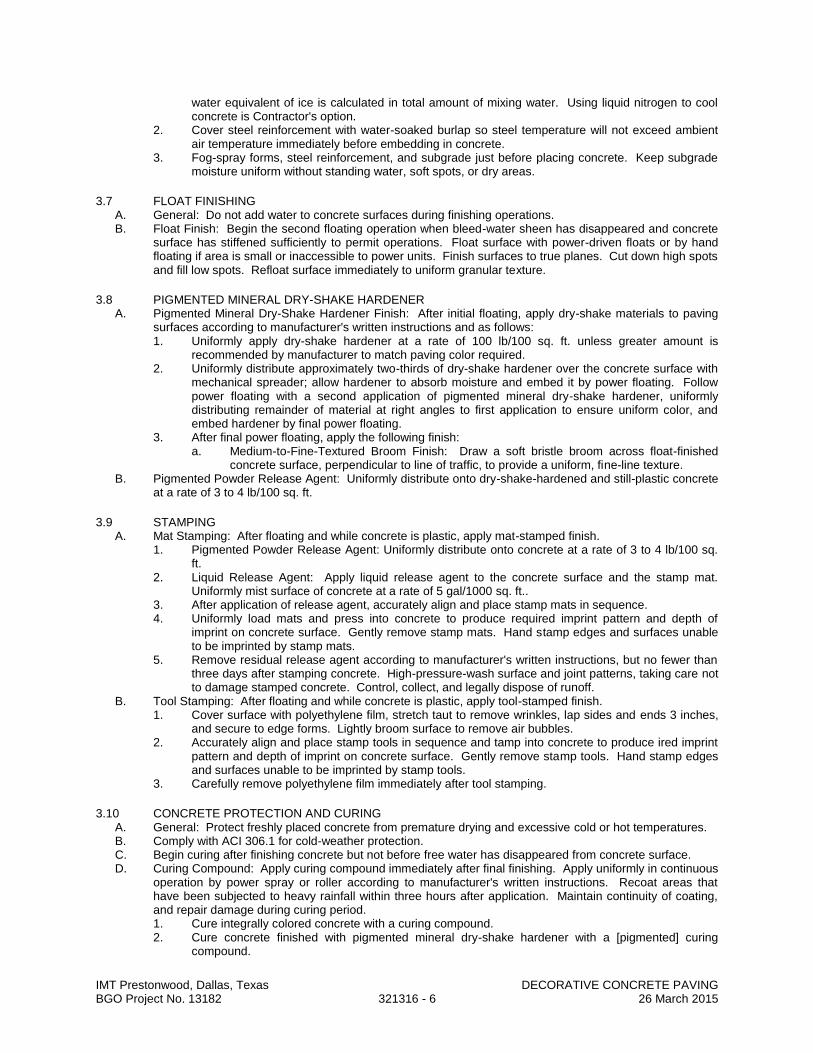
IMT Prestonwood, Dallas, Texas DECORATIVE CONCRETE PAVING BGO Project No. 13182 321316 - 6 26 March 2015
water equivalent of ice is calculated in total amount of mixing water. Using liquid nitrogen to cool concrete is Contractor's option.
2. Cover steel reinforcement with water-soaked burlap so steel temperature will not exceed ambient air temperature immediately before embedding in concrete.
3. Fog-spray forms, steel reinforcement, and subgrade just before placing concrete. Keep subgrade moisture uniform without standing water, soft spots, or dry areas.
3.7 FLOAT FINISHING A. General: Do not add water to concrete surfaces during finishing operations. B. Float Finish: Begin the second floating operation when bleed-water sheen has disappeared and concrete
surface has stiffened sufficiently to permit operations. Float surface with power-driven floats or by hand floating if area is small or inaccessible to power units. Finish surfaces to true planes. Cut down high spots and fill low spots. Refloat surface immediately to uniform granular texture.
3.8 PIGMENTED MINERAL DRY-SHAKE HARDENER A. Pigmented Mineral Dry-Shake Hardener Finish: After initial floating, apply dry-shake materials to paving
surfaces according to manufacturer's written instructions and as follows: 1. Uniformly apply dry-shake hardener at a rate of 100 lb/100 sq. ft. unless greater amount is
recommended by manufacturer to match paving color required. 2. Uniformly distribute approximately two-thirds of dry-shake hardener over the concrete surface with
mechanical spreader; allow hardener to absorb moisture and embed it by power floating. Follow power floating with a second application of pigmented mineral dry-shake hardener, uniformly distributing remainder of material at right angles to first application to ensure uniform color, and embed hardener by final power floating.
3. After final power floating, apply the following finish: a. Medium-to-Fine-Textured Broom Finish: Draw a soft bristle broom across float-finished
concrete surface, perpendicular to line of traffic, to provide a uniform, fine-line texture. B. Pigmented Powder Release Agent: Uniformly distribute onto dry-shake-hardened and still-plastic concrete
at a rate of 3 to 4 lb/100 sq. ft.
3.9 STAMPING A. Mat Stamping: After floating and while concrete is plastic, apply mat-stamped finish.
1. Pigmented Powder Release Agent: Uniformly distribute onto concrete at a rate of 3 to 4 lb/100 sq. ft.
2. Liquid Release Agent: Apply liquid release agent to the concrete surface and the stamp mat. Uniformly mist surface of concrete at a rate of 5 gal/1000 sq. ft..
3. After application of release agent, accurately align and place stamp mats in sequence. 4. Uniformly load mats and press into concrete to produce required imprint pattern and depth of
imprint on concrete surface. Gently remove stamp mats. Hand stamp edges and surfaces unable to be imprinted by stamp mats.
5. Remove residual release agent according to manufacturer's written instructions, but no fewer than three days after stamping concrete. High-pressure-wash surface and joint patterns, taking care not to damage stamped concrete. Control, collect, and legally dispose of runoff.
B. Tool Stamping: After floating and while concrete is plastic, apply tool-stamped finish. 1. Cover surface with polyethylene film, stretch taut to remove wrinkles, lap sides and ends 3 inches,
and secure to edge forms. Lightly broom surface to remove air bubbles. 2. Accurately align and place stamp tools in sequence and tamp into concrete to produce ired imprint
pattern and depth of imprint on concrete surface. Gently remove stamp tools. Hand stamp edges and surfaces unable to be imprinted by stamp tools.
3. Carefully remove polyethylene film immediately after tool stamping.
3.10 CONCRETE PROTECTION AND CURING A. General: Protect freshly placed concrete from premature drying and excessive cold or hot temperatures. B. Comply with ACI 306.1 for cold-weather protection. C. Begin curing after finishing concrete but not before free water has disappeared from concrete surface. D. Curing Compound: Apply curing compound immediately after final finishing. Apply uniformly in continuous
operation by power spray or roller according to manufacturer's written instructions. Recoat areas that have been subjected to heavy rainfall within three hours after application. Maintain continuity of coating, and repair damage during curing period. 1. Cure integrally colored concrete with a curing compound. 2. Cure concrete finished with pigmented mineral dry-shake hardener with a [pigmented] curing
compound.

IMT Prestonwood, Dallas, Texas DECORATIVE CONCRETE PAVING BGO Project No. 13182 321316 - 7 26 March 2015
E. Curing and Sealing Compound: Apply uniformly in continuous operation by power spray or roller according to manufacturer's written instructions. Recoat areas subjected to heavy rainfall within three hours after initial application. Repeat process 24 hours later and apply a second coat. Maintain continuity of coating and repair damage during curing period.
F. Curing Paper: Cure with unwrinkled curing paper in pieces large enough to cover the entire width and edges of slab. Do not lap sheets. Fold curing paper down over paving edges and secure with continuous banks of earth to prevent displacement or billowing due to wind. Immediately repair holes or tears in paper.
3.11 SEALER A. Clear Acrylic Sealer: Apply uniformly in two coats in continuous operations according to manufacturer's
written instructions. Allow first coat to dry before applying second coat, at 90 degrees to the direction of the first coat using same application methods and rates. 1. Begin sealing dry surface no sooner than 14 days after concrete placement. 2. Allow stained concrete surfaces to dry before applying sealer.
3.12 PAVING TOLERANCES A. Comply with tolerances in ACI 117 and as follows:
1. Elevation: 3/4 inch. 2. Thickness: Plus 3/8 inch, minus 1/4 inch. 3. Surface: Gap below 10-foot- long, unleveled straightedge not to exceed 1/2 inch. 4. Lateral Alignment and Spacing of Dowels: 1 inch. 5. Vertical Alignment of Dowels: 1/4 inch. 6. Alignment of Dowel-Bar End Relative to Line Perpendicular to Paving Edge: 1/4 inch per 12 inches
of dowel. 7. Joint Spacing: 3 inches. 8. Contraction Joint Depth: Plus 1/4 inch, no minus. 9. Joint Width: Plus 1/8 inch, no minus.
3.13 FIELD QUALITY CONTROL A. Testing Agency: Engage a qualified testing agency to perform tests and inspections. B. Testing Services: Testing of composite samples of fresh concrete obtained according to ASTM C 172
shall be performed according to the following requirements: 1. Testing Frequency: Obtain at least one composite sample for each 100 cu. yd. or fraction thereof
of each concrete mixture placed each day. a. When frequency of testing will provide fewer than five compressive-strength tests for each
concrete mixture, testing shall be conducted from at least five randomly selected batches or from each batch if fewer than five are used.
2. Slump: ASTM C 143; one test at point of placement for each composite sample, but not less than one test for each day's pour of each concrete mixture. Perform additional tests when concrete consistency appears to change.
3. Air Content: ASTM C 231, pressure method; one test for each composite sample, but not less than one test for each day's pour of each concrete mixture.
4. Concrete Temperature: ASTM C 1064; one test hourly when air temperature is 40 deg F and below and when it is 80 deg F and above, and one test for each composite sample.
5. Compression Test Specimens: ASTM C 31; cast and laboratory cure one set of three standard cylinder specimens for each composite sample.
6. Compressive-Strength Tests: ASTM C 39; test one specimen at seven days and two specimens at 28 days. a. A compressive-strength test shall be the average compressive strength from two specimens
obtained from same composite sample and tested at 28 days. C. Strength of each concrete mixture will be satisfactory if average of any three consecutive compressive-
strength tests equals or exceeds specified compressive strength and no compressive-strength test value falls below specified compressive strength by more than 500 psi.
D. Test results shall be reported in writing to Architect, concrete manufacturer, and Contractor within 48 hours of testing. Reports of compressive-strength tests shall contain Project identification name and number, date of concrete placement, name of concrete testing and inspecting agency, location of concrete batch in Work, design compressive strength at 28 days, concrete mixture proportions and materials, compressive breaking strength, and type of break for both 7- and 28-day tests.
E. Nondestructive Testing: Impact hammer, sonoscope, or other nondestructive device may be permitted by Architect but will not be used as sole basis for approval or rejection of concrete.
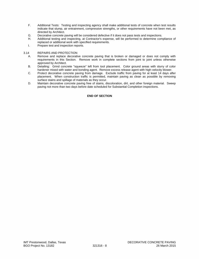
IMT Prestonwood, Dallas, Texas DECORATIVE CONCRETE PAVING BGO Project No. 13182 321316 - 8 26 March 2015
F. Additional Tests: Testing and inspecting agency shall make additional tests of concrete when test results indicate that slump, air entrainment, compressive strengths, or other requirements have not been met, as directed by Architect.
G. Decorative concrete paving will be considered defective if it does not pass tests and inspections. H. Additional testing and inspecting, at Contractor's expense, will be performed to determine compliance of
replaced or additional work with specified requirements. I. Prepare test and inspection reports.
3.14 REPAIRS AND PROTECTION A. Remove and replace decorative concrete paving that is broken or damaged or does not comply with
requirements in this Section. Remove work in complete sections from joint to joint unless otherwise approved by Architect.
B. Detailing: Grind concrete "squeeze" left from tool placement. Color ground areas with slurry of color hardener mixed with water and bonding agent. Remove excess release agent with high-velocity blower.
C. Protect decorative concrete paving from damage. Exclude traffic from paving for at least 14 days after placement. When construction traffic is permitted, maintain paving as clean as possible by removing surface stains and spillage of materials as they occur.
D. Maintain decorative concrete paving free of stains, discoloration, dirt, and other foreign material. Sweep paving not more than two days before date scheduled for Substantial Completion inspections.
END OF SECTION
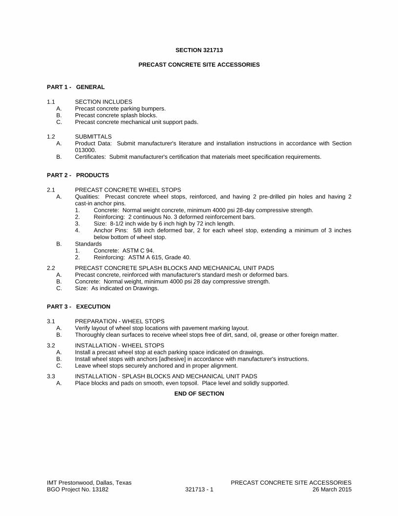
IMT Prestonwood, Dallas, Texas PRECAST CONCRETE SITE ACCESSORIES BGO Project No. 13182 321713 - 1 26 March 2015
SECTION 321713
PRECAST CONCRETE SITE ACCESSORIES
PART 1 - GENERAL
1.1 SECTION INCLUDES A. Precast concrete parking bumpers. B. Precast concrete splash blocks. C. Precast concrete mechanical unit support pads.
1.2 SUBMITTALS A. Product Data: Submit manufacturer's literature and installation instructions in accordance with Section
013000. B. Certificates: Submit manufacturer's certification that materials meet specification requirements.
PART 2 - PRODUCTS
2.1 PRECAST CONCRETE WHEEL STOPS A. Qualities: Precast concrete wheel stops, reinforced, and having 2 pre-drilled pin holes and having 2
cast-in anchor pins. 1. Concrete: Normal weight concrete, minimum 4000 psi 28-day compressive strength. 2. Reinforcing: 2 continuous No. 3 deformed reinforcement bars. 3. Size: 8-1/2 inch wide by 6 inch high by 72 inch length. 4. Anchor Pins: 5/8 inch deformed bar, 2 for each wheel stop, extending a minimum of 3 inches
below bottom of wheel stop. B. Standards
1. Concrete: ASTM C 94. 2. Reinforcing: ASTM A 615, Grade 40.
2.2 PRECAST CONCRETE SPLASH BLOCKS AND MECHANICAL UNIT PADS A. Precast concrete, reinforced with manufacturer's standard mesh or deformed bars. B. Concrete: Normal weight, minimum 4000 psi 28 day compressive strength. C. Size: As indicated on Drawings.
PART 3 - EXECUTION
3.1 PREPARATION - WHEEL STOPS A. Verify layout of wheel stop locations with pavement marking layout. B. Thoroughly clean surfaces to receive wheel stops free of dirt, sand, oil, grease or other foreign matter.
3.2 INSTALLATION - WHEEL STOPS A. Install a precast wheel stop at each parking space indicated on drawings. B. Install wheel stops with anchors [adhesive] in accordance with manufacturer's instructions. C. Leave wheel stops securely anchored and in proper alignment.
3.3 INSTALLATION - SPLASH BLOCKS AND MECHANICAL UNIT PADS A. Place blocks and pads on smooth, even topsoil. Place level and solidly supported.
END OF SECTION

IMT Prestonwood, Dallas, Texas PAINTED PAVEMENT MARKINGS BGO Project No. 13182 321723 - 1 26 March 2015
SECTION 321723
PAINTED PAVEMENT MARKINGS
PART 1 GENERAL
1.1 SECTION INCLUDES A. Parking lot markings, including parking bays, crosswalks, arrows, handicapped symbols, and curb
markings. B. "No Parking" curb painting.
1.2 SUBMITTALS A. See Section 013000 - Administrative Requirements, for submittal procedures. B. Product Data: Manufacturer's data sheets on each product to be used, including:
1. Installation methods.
1.3 DELIVERY, STORAGE, AND HANDLING A. Deliver paint in containers of at least 5 gallons accompanied by batch certificate. B. Store products in manufacturer's unopened packaging until ready for installation. C. Store and dispose of solvent-based materials, and materials used with solvent-based materials, in
accordance with requirements of local authorities having jurisdiction.
1.4 FIELD CONDITIONS A. Do not install products under environmental conditions outside manufacturer's absolute limits.
PART 2 PRODUCTS
2.1 MATERIALS A. Line and Zone Marking Paint: MPI No. 97 Latex Traffic Marking Paint; color(s) as indicated.
1. Roadway Markings: As required by authorities having jurisdiction. 2. Parking Lots: White. 3. Handicapped Symbols: Blue.
B. Temporary Marking Tape: Preformed, reflective, pressure sensitive adhesive tape in color(s) required; Contractor is responsible for selection of material of sufficient durability as to perform satisfactorily during period for which its use is required.
PART 3 EXECUTION
3.1 EXAMINATION A. Do not begin installation until substrates have been properly prepared. B. If substrate preparation is the responsibility of another installer, notify Architect of unsatisfactory
preparation before proceeding.
3.2 PREPARATION A. Allow new pavement surfaces to cure for a period of not less than 14 days before application of
marking materials. B. Prepare surfaces using the methods recommended by the manufacturer for achieving the best result
for the substrate under the project conditions. C. Clean surfaces thoroughly prior to installation.
1. Remove dust, dirt, and other granular surface deposits by sweeping, blowing with compressed air, rinsing with water, or a combination of these methods.
D. Where oil or grease are present, scrub affected areas with several applications of trisodium phosphate solution or other approved detergent or degreaser, and rinse thoroughly after each application; after cleaning, seal oil-soaked areas with cut shellac to prevent bleeding through the new paint.
E. Establish survey control points to determine locations and dimensions of markings; provide templates to control paint application by type and color at necessary intervals.
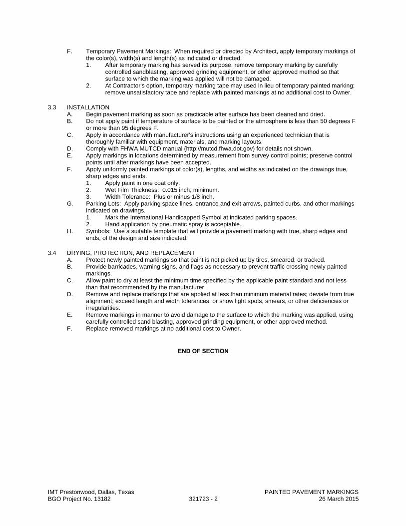
IMT Prestonwood, Dallas, Texas PAINTED PAVEMENT MARKINGS BGO Project No. 13182 321723 - 2 26 March 2015
F. Temporary Pavement Markings: When required or directed by Architect, apply temporary markings of the color(s), width(s) and length(s) as indicated or directed. 1. After temporary marking has served its purpose, remove temporary marking by carefully
controlled sandblasting, approved grinding equipment, or other approved method so that surface to which the marking was applied will not be damaged.
2. At Contractor's option, temporary marking tape may used in lieu of temporary painted marking; remove unsatisfactory tape and replace with painted markings at no additional cost to Owner.
3.3 INSTALLATION A. Begin pavement marking as soon as practicable after surface has been cleaned and dried. B. Do not apply paint if temperature of surface to be painted or the atmosphere is less than 50 degrees F
or more than 95 degrees F. C. Apply in accordance with manufacturer's instructions using an experienced technician that is
thoroughly familiar with equipment, materials, and marking layouts. D. Comply with FHWA MUTCD manual (http://mutcd.fhwa.dot.gov) for details not shown. E. Apply markings in locations determined by measurement from survey control points; preserve control
points until after markings have been accepted. F. Apply uniformly painted markings of color(s), lengths, and widths as indicated on the drawings true,
sharp edges and ends. 1. Apply paint in one coat only. 2. Wet Film Thickness: 0.015 inch, minimum. 3. Width Tolerance: Plus or minus 1/8 inch.
G. Parking Lots: Apply parking space lines, entrance and exit arrows, painted curbs, and other markings indicated on drawings. 1. Mark the International Handicapped Symbol at indicated parking spaces. 2. Hand application by pneumatic spray is acceptable.
H. Symbols: Use a suitable template that will provide a pavement marking with true, sharp edges and ends, of the design and size indicated.
3.4 DRYING, PROTECTION, AND REPLACEMENT A. Protect newly painted markings so that paint is not picked up by tires, smeared, or tracked. B. Provide barricades, warning signs, and flags as necessary to prevent traffic crossing newly painted
markings. C. Allow paint to dry at least the minimum time specified by the applicable paint standard and not less
than that recommended by the manufacturer. D. Remove and replace markings that are applied at less than minimum material rates; deviate from true
alignment; exceed length and width tolerances; or show light spots, smears, or other deficiencies or irregularities.
E. Remove markings in manner to avoid damage to the surface to which the marking was applied, using carefully controlled sand blasting, approved grinding equipment, or other approved method.
F. Replace removed markings at no additional cost to Owner.
END OF SECTION
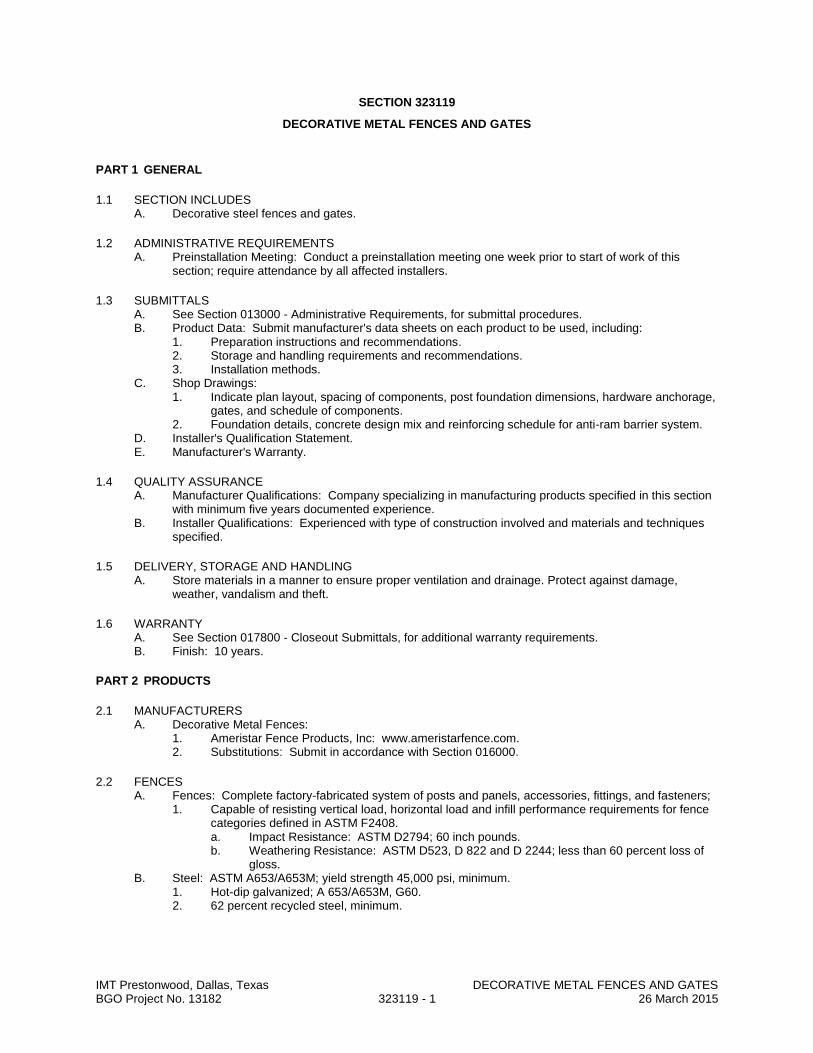
IMT Prestonwood, Dallas, Texas DECORATIVE METAL FENCES AND GATES BGO Project No. 13182 323119 - 1 26 March 2015
SECTION 323119
DECORATIVE METAL FENCES AND GATES
PART 1 GENERAL
1.1 SECTION INCLUDES A. Decorative steel fences and gates.
1.2 ADMINISTRATIVE REQUIREMENTS A. Preinstallation Meeting: Conduct a preinstallation meeting one week prior to start of work of this
section; require attendance by all affected installers.
1.3 SUBMITTALS A. See Section 013000 - Administrative Requirements, for submittal procedures. B. Product Data: Submit manufacturer's data sheets on each product to be used, including:
1. Preparation instructions and recommendations. 2. Storage and handling requirements and recommendations. 3. Installation methods.
C. Shop Drawings: 1. Indicate plan layout, spacing of components, post foundation dimensions, hardware anchorage,
gates, and schedule of components. 2. Foundation details, concrete design mix and reinforcing schedule for anti-ram barrier system.
D. Installer's Qualification Statement. E. Manufacturer's Warranty.
1.4 QUALITY ASSURANCE A. Manufacturer Qualifications: Company specializing in manufacturing products specified in this section
with minimum five years documented experience. B. Installer Qualifications: Experienced with type of construction involved and materials and techniques
specified.
1.5 DELIVERY, STORAGE AND HANDLING A. Store materials in a manner to ensure proper ventilation and drainage. Protect against damage,
weather, vandalism and theft.
1.6 WARRANTY A. See Section 017800 - Closeout Submittals, for additional warranty requirements. B. Finish: 10 years.
PART 2 PRODUCTS
2.1 MANUFACTURERS A. Decorative Metal Fences:
1. Ameristar Fence Products, Inc: www.ameristarfence.com. 2. Substitutions: Submit in accordance with Section 016000.
2.2 FENCES A. Fences: Complete factory-fabricated system of posts and panels, accessories, fittings, and fasteners;
1. Capable of resisting vertical load, horizontal load and infill performance requirements for fence categories defined in ASTM F2408. a. Impact Resistance: ASTM D2794; 60 inch pounds. b. Weathering Resistance: ASTM D523, D 822 and D 2244; less than 60 percent loss of
gloss. B. Steel: ASTM A653/A653M; yield strength 45,000 psi, minimum.
1. Hot-dip galvanized; A 653/A653M, G60. 2. 62 percent recycled steel, minimum.
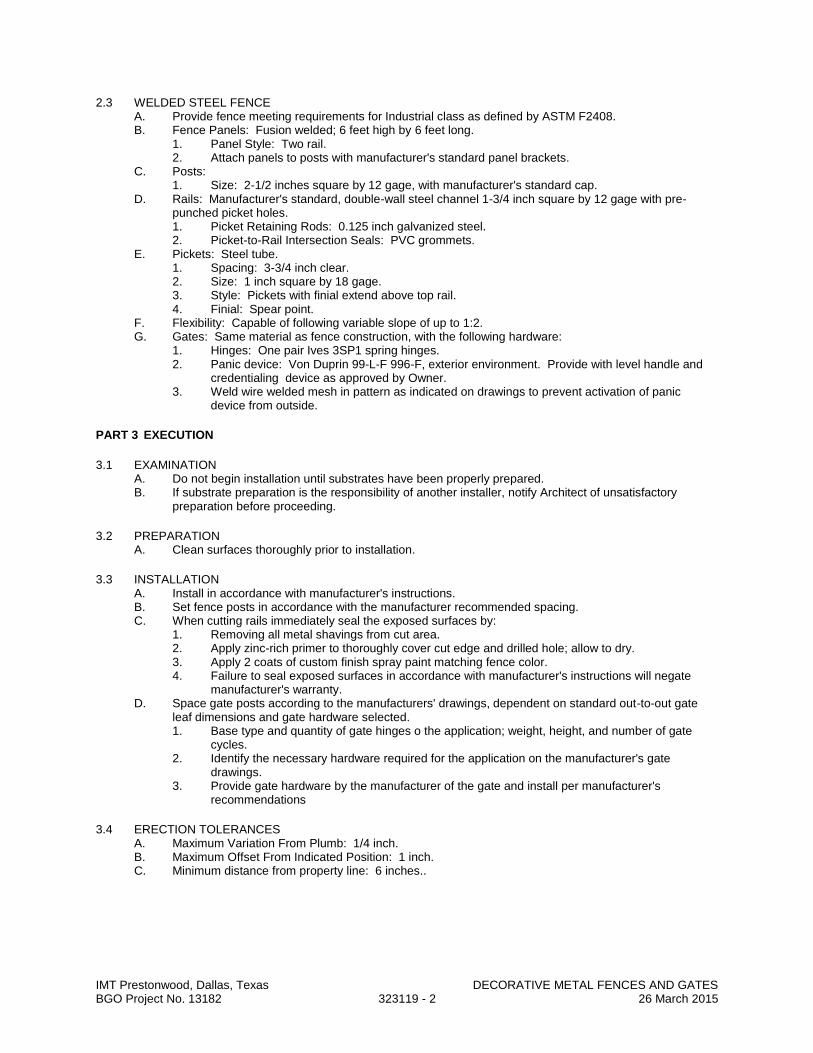
IMT Prestonwood, Dallas, Texas DECORATIVE METAL FENCES AND GATES BGO Project No. 13182 323119 - 2 26 March 2015
2.3 WELDED STEEL FENCE A. Provide fence meeting requirements for Industrial class as defined by ASTM F2408. B. Fence Panels: Fusion welded; 6 feet high by 6 feet long.
1. Panel Style: Two rail. 2. Attach panels to posts with manufacturer's standard panel brackets.
C. Posts: 1. Size: 2-1/2 inches square by 12 gage, with manufacturer's standard cap.
D. Rails: Manufacturer's standard, double-wall steel channel 1-3/4 inch square by 12 gage with pre-punched picket holes. 1. Picket Retaining Rods: 0.125 inch galvanized steel. 2. Picket-to-Rail Intersection Seals: PVC grommets.
E. Pickets: Steel tube. 1. Spacing: 3-3/4 inch clear. 2. Size: 1 inch square by 18 gage. 3. Style: Pickets with finial extend above top rail. 4. Finial: Spear point.
F. Flexibility: Capable of following variable slope of up to 1:2. G. Gates: Same material as fence construction, with the following hardware:
1. Hinges: One pair Ives 3SP1 spring hinges. 2. Panic device: Von Duprin 99-L-F 996-F, exterior environment. Provide with level handle and
credentialing device as approved by Owner. 3. Weld wire welded mesh in pattern as indicated on drawings to prevent activation of panic
device from outside.
PART 3 EXECUTION
3.1 EXAMINATION A. Do not begin installation until substrates have been properly prepared. B. If substrate preparation is the responsibility of another installer, notify Architect of unsatisfactory
preparation before proceeding.
3.2 PREPARATION A. Clean surfaces thoroughly prior to installation.
3.3 INSTALLATION A. Install in accordance with manufacturer's instructions. B. Set fence posts in accordance with the manufacturer recommended spacing. C. When cutting rails immediately seal the exposed surfaces by:
1. Removing all metal shavings from cut area. 2. Apply zinc-rich primer to thoroughly cover cut edge and drilled hole; allow to dry. 3. Apply 2 coats of custom finish spray paint matching fence color. 4. Failure to seal exposed surfaces in accordance with manufacturer's instructions will negate
manufacturer's warranty. D. Space gate posts according to the manufacturers' drawings, dependent on standard out-to-out gate
leaf dimensions and gate hardware selected. 1. Base type and quantity of gate hinges o the application; weight, height, and number of gate
cycles. 2. Identify the necessary hardware required for the application on the manufacturer's gate
drawings. 3. Provide gate hardware by the manufacturer of the gate and install per manufacturer's
recommendations
3.4 ERECTION TOLERANCES A. Maximum Variation From Plumb: 1/4 inch. B. Maximum Offset From Indicated Position: 1 inch. C. Minimum distance from property line: 6 inches..
IMT Prestonwood, Dallas, Texas DECORATIVE METAL FENCES AND GATES BGO Project No. 13182 323119 - 3 26 March 2015
3.5 CLEANING A. Leave immediate work area neat at end of each work day. B. Clean jobsite of excess materials; scatter excess material from post hole excavations uniformly away
from posts. Remove excess material if required. C. Clean fence with mild household detergent and clean water rinse well. . D. Remove mortar from exposed posts and other fencing material using a 10 percent solution of muriatic
acid followed immediately by several rinses with clean water. E. Touch up scratched surfaces using materials recommended by manufacturer. Match touchup paint
color to fence finish.
3.6 PROTECTION A. Protect installed products until completion of project. B. Touch-up, repair, or replace damaged products before Substantial Completion.
END OF SECTION

IMT Prestonwood, Dallas, Texas SECURITY GATES AND OPERATORS BGO Project No. 13182 323136 - 1 26 March 2015
SECTION 323136
SECURITY GATES AND OPERATORS
PART 1 GENERAL
1.1 SECTION INCLUDES A. Security gates. B. Controls and related wiring.
1.2 ADMINISTRATIVE REQUIREMENTS A. Coordination: Coordinate installation of units with size, location and installation of service utilities. B. Preinstallation Meeting: Conduct a preinstallation meeting one week prior to the start of work of this
section; require attendance by all affected installers. C. Sequencing: Ensure that utility connections are completed in an orderly and expeditious manner.
1.3 SUBMITTALS A. See Section 013000 - Administrative Requirements, for submittal procedures. B. Shop Drawings: Provide detailed drawings showing:
1. Layout and overall dimensions of each major element of the barrier equipment, including the hydraulic power unit and operator control panels, if applicable.
2. Foundation and anchoring requirements of the barrier equipment. 3. Hydraulic schematic drawing showing size and number of hoses required to run between the
barrier device and the hydraulic power unit. 4. Electrical schematic including associated wiring, showing all electrically connected components,
including interface points for connection to equipment; indicate minimum conduit size and number of wires required to run between each component of the barrier equipment.
5. Schematic drawings of the entire barrier system, with all manufacturer supplied equipment connected and integrated.
C. Operation and Maintenance Data.
PART 2 PRODUCTS
2.1 MATERIALS/FEATURES A. California Type Operators: Door King Model 1150 or comparable by Sentex or Elite. Provide
emergency over-ride for Fire and EMT vehicles that allow all gates to open simultaneously. B. Gates: Custom fabricated of frame and pickets to match adjacent fencing. C. Provide with RFID security access reader compatible with Owner furnished tenant credentialing device.
2.2 SECURITY GATES AND BARRIERS A. Security Gates and Barriers: Factory-fabricated, -assembled, and -tested devices, including all
components for satisfactory operation; capable of resisting specified impact when installed in foundations indicated on drawings.
B. Material: Hot-dipped galvanized steel with painted finish. C. Color: As selected from manufacturer's standard.
D. Gates and operators must meet UL 325 and ASTM F2200 requirements.
2.3 VEHICLE DETECTORS A. Vehicle Loop Detector System: Provide self-tuning electronic detector with adjustable detection
patterns, adjustable sensitivity and frequency settings, and panel indicator light designed to detect presence or transit of a vehicle over an embedded loop of wire and to emit signal activating gate-arm operator. Include automatic closing timer with adjustable time delay before closing and vehicle loop detector designed to hold gate arm open until traffic clears. Provide number of loops consisting of multiple strands of wire, number of turns, loop size, and method of placement at location shown on Drawings, as recommended in writing by detection system manufacturer for function indicated. 1. Factory-Formed Loop: Wire, preformed in size indicated; style for saw-cut installation. 2. System Performance: Capable of the following:
a. Recognize two vehicles within 6 inches of each other on standard-sized loop. b. Recognize vehicle direction by detecting vehicle moving from one loop to another. c. Generate reverse count if vehicle backs up after generating directional count in forward
direction.
IMT Prestonwood, Dallas, Texas SECURITY GATES AND OPERATORS BGO Project No. 13182 323136 - 2 26 March 2015
i) Continuous diagnostic monitoring for intermittently operating and failed loops.
ii) Crosstalk test between adjacent loops. B. Vehicle Presence Detector: Provide emitter/receiver-type detector with adjustable detection zone
pattern and sensitivity, designed to detect the presence or transit of vehicle in gate-arm pathway by interrupting infrared beam in zone pattern and to emit signal activating gate-arm operator. Include automatic closing timer with adjustable time delay before closing and vehicle presence detector designed to.
PART 3 EXECUTION
3.1 EXAMINATION A. Verification of Conditions:
1. Verify location of existing utilities, grades and conditions of substrate. 2. Verify existing vehicle detector loops, including their size, geometry and wiring. 3. Verify integration requirements with other site security equipment including but not limited to
card readers, tire puncture devices, gates and other automated barrier systems.
3.2 PREPARATION A. Protect existing work from damage due to installation of this work.
3.3 INSTALLATION A. Install in accordance with manufacturer's instructions.
3.4 FIELD QUALITY CONTROL A. See Section 014000 - Quality Requirements, for additional requirements. B. Provide manufacturer's certified, field supervisor during key milestones of the installation of the barrier.
3.5 SYSTEM STARTUP A. Provide manufacturer's field representative to observe systems startup. B. Prepare and start equipment in accordance with manufacturers' instructions and recommendations. C. Adjust for proper operation within manufacturer's published tolerances.
3.6 CLEANING A. Touch up scratched surfaces using materials recommended by manufacturer. Match touchup paint
color with barrier finish. B. See Section 017419 - Construction Waste Management and Disposal for additional requirements.
3.7 CLOSEOUT ACTIVITIES A. See Section 017800 - Closeout Submittals, for closeout submittals. B. See Section 017900 - Demonstration and Training, for additional requirements. C. Demonstration: Demonstrate operation of the barrier to Owner's personnel.
1. Use operation and maintenance data as reference during demonstration. 2. Briefly describe function, operation, and maintenance of each component.
D. Training: Train Owner's personnel on operation and maintenance of the barrier. 1. Use operation and maintenance manual as training reference, supplemented with additional
training materials as required. 2. Provide minimum of two hours of training.
3.8 PROTECTION A. Protect installed units from subsequent construction operations.
3.9 MAINTENANCE A. See Section 017000 - Execution Requirements, for additional requirements relating to maintenance
service. B. Provide a separate maintenance contract for specified maintenance service.
END OF SECTION
March 2, 2015
Oden Hughes901 S. Mopac Freeway BOP 5, Suite 200Austin, Texas 78746 Attention: Howell Beaver
RE: IMT Prestonwood, Dallas, Texas SUB: Environmental Noise Mitigation Study
Dear Mr. Beaver:
At your request, dP(A) Acoustics, Inc., has conducted an environmental noise study for the IMT Prestonwood project to analyze and to mitigate the traffic noise from the nearby highway and the streets and the railroad noise from DART.
This report provides the acoustical recommendations for the building exterior on items such as the facade wall, the roof, the windows, the exterior doors, etc., The available documents were used for this study.
The report is divided in to five (5) sections:
• Section I shows the site, and the nearby highway and the streets, • Section II describes the goal the acoustical criteria for indoor noise level at the apartment units, • Section III explains the field noise measurements, • Section IV describes the unit types, window & patio door schedules, • Section V provides the acoustical recommendations to meet the established indoor noise level.
Section IDescription of the Site A Sketch SK-1 shows the site, the Dallas North Tollway and Arapaho Road.
B Sketch SK-2 shows the pictures of Dallas North Tollway near the site identifying the elements; the retaining walls makes the tollway as a “tunnel”, and increase the noise levels further.
dP(A) Acoustics, Inc.9319 LBJ Freeway, Suite 216Dallas, Texas 75243
V 972-644-2130
W www.dpaacoustics.netE [email protected]
Section IIGoal on the Acoustical Criteria for Indoor Noise Levels at Apartment Units A Interior noise levels as well as environmental noise sources are measured in decibels using a descriptor known as A-weighting which tend to represent the frequency characteristics of the human ear.
B US Department of Housing and Urban Development (HUD) recommends 45 dB(A) for interior spaces regardless of what these spaces are. This has been taken as the “acoustical goal” for the interior spaces in the design of the building exterior. To obtain interior noise levels lower than 45 dB(A) will increase the budget substantially. Based on my experience in urban multifamily projects, the interior noise level of 45 dB(A) is acceptable for this project.
C The ability of a building assembly (such as the window) in the transmission of the sound is determined by its Sound Transmission Class (STC) rating. The actual amount of the required STC rating of a building assembly is determined by the area it occupies in a building assembly. For example, the required STC rating of a window is determined by how much area it occupies in the facade wall.
Section IIIField Noise Measurements
A The noise impact is from the following sources: • AutomobiletrafficonDallasNorthTollway • AutomobiletrafficonArapahoRoad
B The traffic on Arapaho Road is very minimal, and is not an acoustical issue.
C Field noise measurements were performed at the site to measure the noise impact from the traffic on Dallas North Tollway as well as on Arapaho Road. The measurements were performed using the A-Weighting scale in the analyzer for the acoustical descriptor Leq which is used to assess environmental noise. The noise measurements were performed on weekdays and weekends at day, evening and night.
D Sketch SK-4 shows the building and the anticipated noise levels at the facades at Level 1 through Level 4. Two (2)) acoustical zones are established based on the outdoor noise levels. Acoustical Zone-1 (red) and Acoustical Zone-2 (blue) are shown in Sketch SK-5; these zones require upgraded windows and patio doors. All other facades falls under Non-Acoustical Zone; this zone only needs the typical windows and patio doors that are normally used in wood-framed multi-family projects.
dP(A) Acoustics, Inc.
IMT Prestonwood, Dallas, TexasEnvironmental Noise Mitigation StudyReport to Oden HughesMarch 2, 2015Page 2 of 6

E The acoustical recommendations are given in Section V.
Section IV
Unit Types, Window & Patio Door Schedules
A The % area of Windows and Patio Doors in the Facade Walls are given below:
Unit Type % Area of the Windows & Patio Doors in Specific Room/Area
Living/Dining Bed Room#1 Bed Room#2
E1 20% None N/A
A1 20% 20% N/A
A2 28% 18% N/A
A3 20% None N/A
A4 20% 28% N/A
A5 12% 15% N/A
A5b 17% 10% N/A
A6 20% 15% N/A
A7 30% 12% N/A
A8 10% 6% N/A
B1 30% 28% 30%
B2 30% 30% 30%
B3 40% 18% 18%
B3a 40% 18% 18%
B4 33% 15% 15%
B5a 75% 30% 60%
B This information was used in determining the STC requirements for the facade wall, the windows
and patio doors.
dP(A) Acoustics, Inc.
IMT Prestonwood, Dallas, TexasEnvironmental Noise Mitigation StudyReport to Oden HughesMarch 2, 2015Page 3 of 6
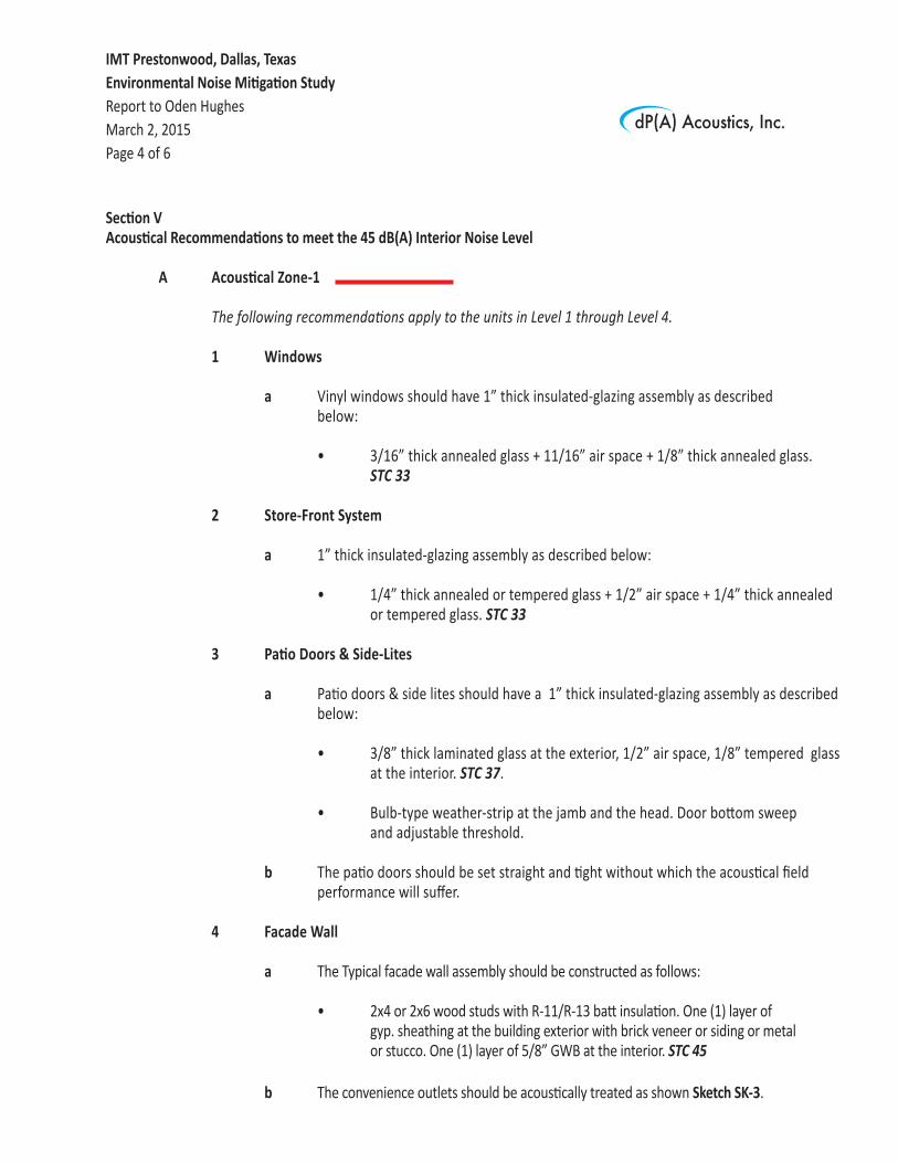
Section V Acoustical Recommendations to meet the 45 dB(A) Interior Noise Level
A Acoustical Zone-1
ThefollowingrecommendationsapplytotheunitsinLevel1throughLevel4. 1 Windows
a Vinyl windows should have 1” thick insulated-glazing assembly as described below:
• 3/16” thick annealed glass + 11/16” air space + 1/8” thick annealed glass. STC 33
2 Store-Front System a 1” thick insulated-glazing assembly as described below:
• 1/4” thick annealed or tempered glass + 1/2” air space + 1/4” thick annealed or tempered glass. STC 33
3 Patio Doors & Side-Lites
a Patio doors & side lites should have a 1” thick insulated-glazing assembly as described below:
• 3/8” thick laminated glass at the exterior, 1/2” air space, 1/8” tempered glass at the interior. STC 37. • Bulb-type weather-strip at the jamb and the head. Door bottom sweep and adjustable threshold.
b The patio doors should be set straight and tight without which the acoustical field performance will suffer.
4 Facade Wall
a The Typical facade wall assembly should be constructed as follows:
• 2x4 or 2x6 wood studs with R-11/R-13 batt insulation. One (1) layer of gyp. sheathing at the building exterior with brick veneer or siding or metal or stucco. One (1) layer of 5/8” GWB at the interior. STC 45
b The convenience outlets should be acoustically treated as shown Sketch SK-3.
dP(A) Acoustics, Inc.
IMT Prestonwood, Dallas, TexasEnvironmental Noise Mitigation StudyReport to Oden HughesMarch 2, 2015Page 4 of 6
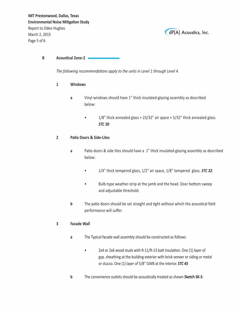
B Acoustical Zone-2
ThefollowingrecommendationsapplytotheunitsinLevel1throughLevel4. 1 Windows
a Vinyl windows should have 1” thick insulated-glazing assembly as described below:
• 1/8” thick annealed glass + 23/32” air space + 5/32” thick annealed glass. STC 30
2 Patio Doors & Side-Lites
a Patio doors & side lites should have a 1” thick insulated-glazing assembly as described below:
• 1/4” thick tempered glass, 1/2” air space, 1/8” tempered glass. STC 32. • Bulb-type weather-strip at the jamb and the head. Door bottom sweep and adjustable threshold.
b The patio doors should be set straight and tight without which the acoustical field performance will suffer.
3 Facade Wall
a The Typical facade wall assembly should be constructed as follows:
• 2x4 or 2x6 wood studs with R-11/R-13 batt insulation. One (1) layer of gyp. sheathing at the building exterior with brick veneer or siding or metal or stucco. One (1) layer of 5/8” GWB at the interior. STC 45
b The convenience outlets should be acoustically treated as shown Sketch SK-3.
dP(A) Acoustics, Inc.
IMT Prestonwood, Dallas, TexasEnvironmental Noise Mitigation StudyReport to Oden HughesMarch 2, 2015Page 5 of 6

C Non-Acoustical Zone ThefollowingrecommendationsapplytotheunitsinLevel1throughLevel4. 1 Windows
a Vinyl windows should have a 1/2” thick insulated-glazing assembly as described below:
• Two (2) pieces of 1/8” thick annealed or tempered glass separated by an air space of 1/2”. STC 27
2 Patio Doors
a Patio doors should have a 1” thick insulated-glazing assembly as described below:
• Two (2) pieces of 1/8” thick annealed or tempered glass separated by an air space of 3/4”. STC 28.
3 Facade Wall
a The Typical facade wall assembly should be constructed as follows:
• 2x4 or 2x6 wood studs with R-11/R-13 batt insulation. One (1) layer of gyp. sheathing at the building exterior with brick veneer or siding or metal tile or stucco. One (1) layer of 5/8” GWB at the interior. STC 45
Thank you.
Sincerely,
DP AyyappanPresident
DPA
Attachment: Sketch SK-1 through Sketch SK-5 dated March 2, 2015
dP(A) Acoustics, Inc.
IMT Prestonwood, Dallas, TexasEnvironmental Noise Mitigation StudyReport to Oden HughesMarch 2, 2015Page 6 of 6
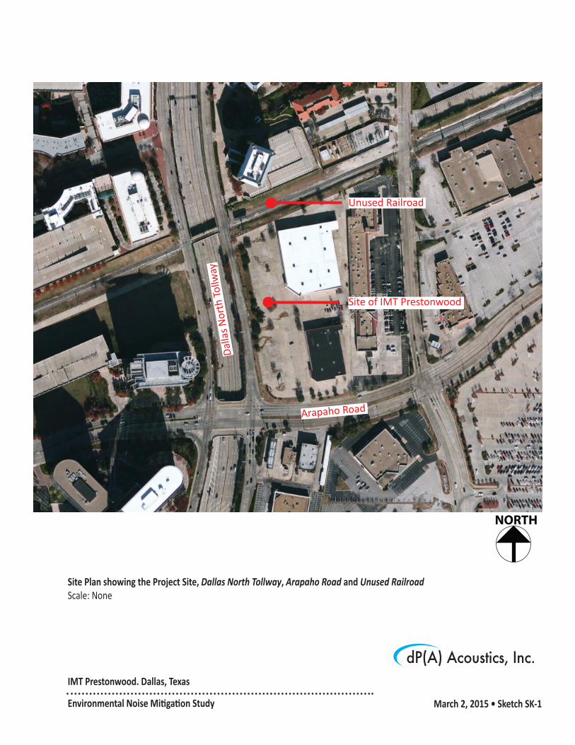
IMT Prestonwood. Dallas, Texas
Environmental Noise Mitigation Study March 2, 2015 • Sketch SK-1
Site Plan showing the Project Site, Dallas North Tollway, Arapaho Road and Unused RailroadScale: None
dP(A) Acoustics, Inc.
NORTH
Site of IMT Prestonwood
Dal
las
Nor
th T
ollw
ay
Arapaho Road
Unused Railroad

IMT Prestonwood, Dallas, Texas
Environmental Noise Mitigation Study March 2, 2015 • Sketch SK-2
Pictures of Dallas North Tollway near SiteScale: None
dP(A) Acoustics, Inc.
Tollway is at about 20’ below the site.
Concrete Wall. (Typical at the opposite side)
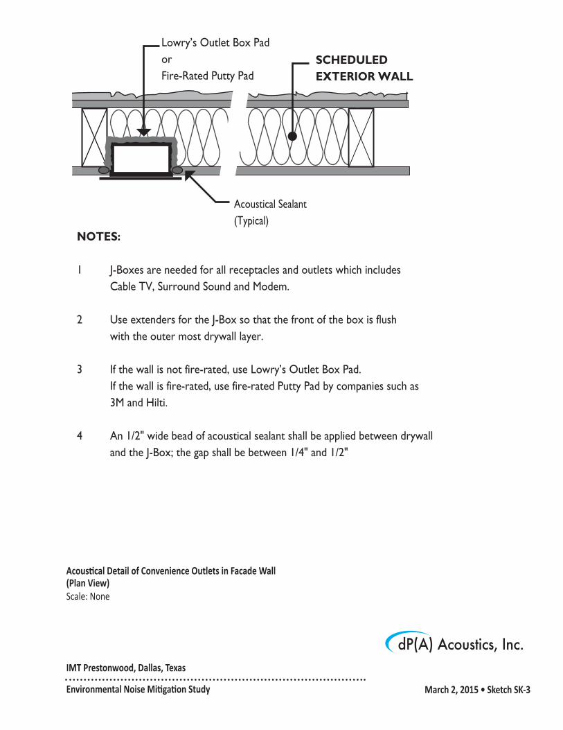
Acoustical Detail of Convenience Outlets in Facade Wall (Plan View)Scale: None
dP(A) Acoustics, Inc.
Acoustical Sealant(Typical)
NOTES:
1 J-Boxes are needed for all receptacles and outlets which includes Cable TV, Surround Sound and Modem.
2 Use extenders for the J-Box so that the front of the box is flush with the outer most drywall layer.
3 If the wall is not fire-rated, use Lowry’s Outlet Box Pad. If the wall is fire-rated, use fire-rated Putty Pad by companies such as 3M and Hilti.
4 An 1/2" wide bead of acoustical sealant shall be applied between drywall and the J-Box; the gap shall be between 1/4" and 1/2"
Lowry’s Outlet Box PadorFire-Rated Putty Pad
SCHEDULED EXTERIOR WALL
IMT Prestonwood, Dallas, Texas
Environmental Noise Mitigation Study March 2, 2015 • Sketch SK-3

dP(A) Acoustics, Inc.IMT Prestonwood, Dallas, Texas
Environmental Noise Mitigation Study March 2, 2015 • Sketch SK-4
Site Plan showing Anticipated Outdoor Noise LevelsScale: None
NORTH

dP(A) Acoustics, Inc.IMT Prestonwood, Dallas, Texas
Environmental Noise Mitigation Study March 2, 2015 • Sketch SK-5
Site Plan showing Acoustical Zone-1 and Acoustical Zone-2Scale: None
NORTH