for gsm/cdma rf site transmitters series nmvw0900-20™ nmvw1800 … · · 2009-12-01for gsm/cdma...
TRANSCRIPT

for GSM/CDMA RF site transmitters
series NMVW0900-20™ NMVW1800-20™ NMVW1900-20™ NMVW0450-20™
Reference manual & Technical specification
NMVW/D-RM/EN Revision 3
June, 2004
Advanced digital VSWR Monitor
2
Description The NMVWxxxx-20 series features an advanced digital VSWR monitor, designed for reliable, long term GSM/CDMA site transmitter RF monitoring. The device provides alarms for the malfunctions found on the RF path like antenna, connectors or cable damages. The monitor is designed for the following 4 bands:
band frequency product code 900 MHz NMVW0900-20
1800 MHz NMVW1800-20 1900 MHz NMVW1900-20
450 MHz NMVW0450-20 thus covering the entire mobile transmissions bands. Through directional couplers and microprocessor control the device provides “state of the art” accuracy and functional versatility. Using an intelligent algorithm base on data interpolation, the device avoids false alarms, and provides a better way to minimize GSM/CDMA coverage malfunctions of the network. The control channel can be used for sending the alarms from the site to the supervising center. Connectivity Using a terminal mode programming feature, the device can be calibrated and programmed from a computer using any kind of OS. Using an RS232/RS485 external bus, the device can provide logs of full measured parameters in a user-desired form. Up to 255 devices can be linked up in 1 network using the existing RS485 bus. Extensions (available optional)
display extension with navigate, init and program buttons (for real-time RF measurement without interaction into the RF path)
RS232 or USB cable extension for programming MMC (FAT16) card logger extension which support up to 128Mb MMC cards
The logging data formats can be chosen from a list available in the programming menu. All slave devices and expansion boards are hot-pluggable and plug-and-play.
Operation The programming menus are user friendly and provide an explanation for each step of the functional routines. Two operation modes are possible:
terminal mode (set the terminal to following parameters: 38400 baud, 8, N, 1) stand alone mode
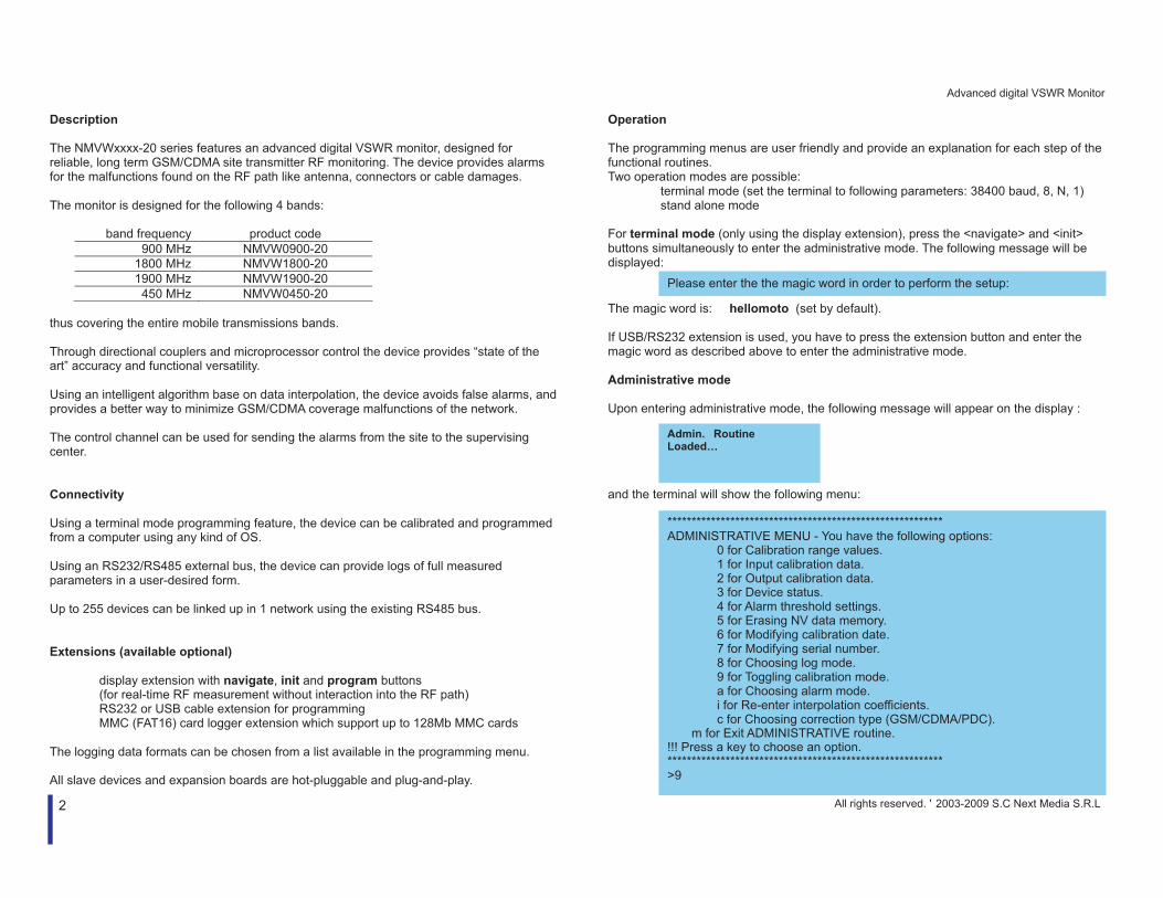
For terminal mode (only using the display extension), press the <navigate> and <init> buttons simultaneously to enter the administrative mode. The following message will be displayed: The magic word is: hellomoto (set by default). If USB/RS232 extension is used, you have to press the extension button and enter the magic word as described above to enter the administrative mode. Administrative mode Upon entering administrative mode, the following message will appear on the display : and the terminal will show the following menu:
********************************************************* ADMINISTRATIVE MENU - You have the following options:
0 for Calibration range values. 1 for Input calibration data. 2 for Output calibration data. 3 for Device status. 4 for Alarm threshold settings. 5 for Erasing NV data memory. 6 for Modifying calibration date. 7 for Modifying serial number. 8 for Choosing log mode. 9 for Toggling calibration mode. a for Choosing alarm mode. i for Re-enter interpolation coefficients. c for Choosing correction type (GSM/CDMA/PDC).
m for Exit ADMINISTRATIVE routine. !!! Press a key to choose an option. ********************************************************* >9
Please enter the the magic word in order to perform the setup:
Admin. Routine Loaded…
All rights reserved. ' 2003-2009 S.C Next Media S.R.L
Advanced digital VSWR Monitor
3
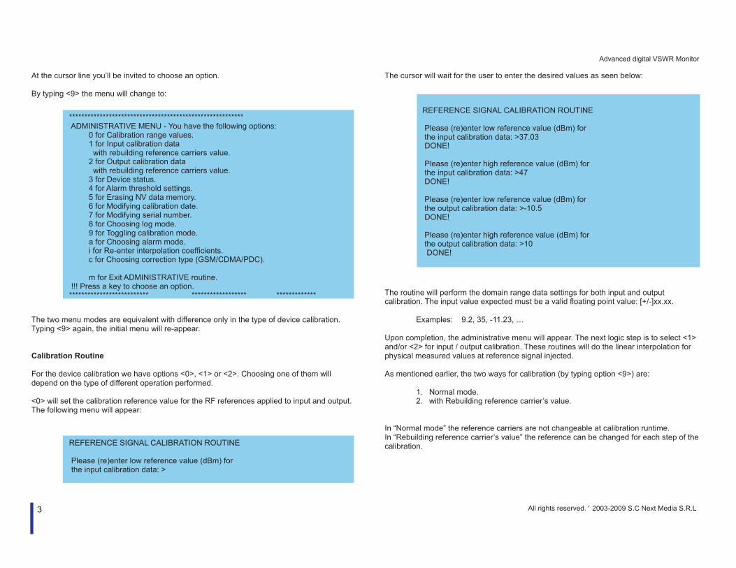
At the cursor line you’ll be invited to choose an option. By typing <9> the menu will change to: The two menu modes are equivalent with difference only in the type of device calibration. Typing <9> again, the initial menu will re-appear. Calibration Routine For the device calibration we have options <0>, <1> or <2>. Choosing one of them will depend on the type of different operation performed. <0> will set the calibration reference value for the RF references applied to input and output. The following menu will appear:
The cursor will wait for the user to enter the desired values as seen below: The routine will perform the domain range data settings for both input and output calibration. The input value expected must be a valid floating point value: [+/-]xx.xx.
Examples: 9.2, 35, -11.23, … Upon completion, the administrative menu will appear. The next logic step is to select <1> and/or <2> for input / output calibration. These routines will do the linear interpolation for physical measured values at reference signal injected. As mentioned earlier, the two ways for calibration (by typing option <9>) are:
1. Normal mode. 2. with Rebuilding reference carrier’s value.
In “Normal mode” the reference carriers are not changeable at calibration runtime. In “Rebuilding reference carrier’s value” the reference can be changed for each step of the calibration.
********************************************************* ADMINISTRATIVE MENU - You have the following options: 0 for Calibration range values. 1 for Input calibration data with rebuilding reference carriers value. 2 for Output calibration data with rebuilding reference carriers value. 3 for Device status. 4 for Alarm threshold settings. 5 for Erasing NV data memory. 6 for Modifying calibration date. 7 for Modifying serial number. 8 for Choosing log mode. 9 for Toggling calibration mode. a for Choosing alarm mode. i for Re-enter interpolation coefficients. c for Choosing correction type (GSM/CDMA/PDC). m for Exit ADMINISTRATIVE routine. !!! Press a key to choose an option. ************************** ****************** *************
REFERENCE SIGNAL CALIBRATION ROUTINE Please (re)enter low reference value (dBm) for the input calibration data: >
REFERENCE SIGNAL CALIBRATION ROUTINE Please (re)enter low reference value (dBm) for the input calibration data: >37.03 DONE! Please (re)enter high reference value (dBm) for the input calibration data: >47 DONE! Please (re)enter low reference value (dBm) for the output calibration data: >-10.5 DONE! Please (re)enter high reference value (dBm) for the output calibration data: >10 DONE!
All rights reserved. ' 2003-2009 S.C Next Media S.R.L

Advanced digital VSWR Monitor
4
In “Normal mode” the following menu will appear: (steps described hereby apply equally for both input and output calibrations) By pressing any key the device will perform self calibration using as reference the 10.00dBm carrier value from the signal generator. When the user performs the input calibration, the RF generator must be connected to the device input port, and the device output must be terminated with 50 Ohm. WARNING! For correct calibration, please choose for minimum value/maximum value a carrier who is in a 10% - 90% range of FS. The calibration can be performed using a sine refference signal or GSM (All Time Slots On)/CDMA (Forward Link, 9 Channels On)/PDC (All Time Slots On) carrier. The “Medium value” represents the real measured data (steps and %) of the medium measured values. The user will choose as references the limit values of the measured signal (maximum and minimum direct measured and wave power reflected). By typing <y> the data will be saved into the EEPROM. Based on two different input values, this routine will compute linear interpolation coefficients that describe the linear indication for the whole direct wave measurement interval.
The same routine will be performed for the output, in this case the reference RF generator must be connected to the device output, and the input must be terminated with 50 Ohm. In “Rebuilding reference carriers” mode the reference value are not fixed and will be entered in the input/output calibration routine; the reference values can be / not preset in option <0> from the main menu. In this mode, values given in option <0> will be reconsidered. Device status is available typing <3> in the administrative menu:
INPUT CALIBRATION ROUTINE 1’st Input calibration data. Please connect at the input an 10.00 dBm carrier from the RF Signal generator, and press any key when you are ready...
Performing 1’st calibration step!.......... DONE! (Medium Value=496.0) - (10.0% FS) 2’nd Input calibration data. Please connect at the input an 20.00 dBm carrier from the RF Signal generator, and press any key when you are ready... Performing 2’nd calibration step!.......... DONE! (Medium Value=2048.0) - (50.0% FS) Calibration coefficients computation for the input is now complete. Linear interpolation done by formula: (0.01044445)*X+(23.00729012)=Y Do you want to save data? (Y/N) >y
1’st Input calibration data. Rebuilding reference mode detect... Please (re)enter low reference value (dBm) for the input calibration data: >30 DONE! Please connect at the input an 30.00 dBm carrier from the RF Signal generator, and press any key when you are ready... Performing 1’st calibration step!.......... DONE! (Medium Value=496.0) - (10.0% FS)
********************************************************** DEVICE STATUS: Input Calibration @ 1044445.000 dBm/ NaN dBm. -> coefficients: (A=0.01044445), (B=23.70133000). Output Calibration @ NaN dBm/ NaN dBm. -> coefficients: (A=0.01087344), (B=-5.64082100). VSWR Low Threshold: 1.50. VSWR High Threshold: 1.60. Power Low Threshold: 37.00 dBm. Power High Threshold: 41.00 dBm. Correction type: -PDC Channel (All Time Slots On). Last Calibration Date (dd/mm/yyyy): 2/04/2003. SN: 000000012. Log MODE: ’f’. Calibration MODE: Normal. Alarm MODE: VSWR. ********************************************************** press any key to return to main menu...
All rights reserved. ' 2003-2009 S.C Next Media S.R.L
Advanced digital VSWR Monitor
5
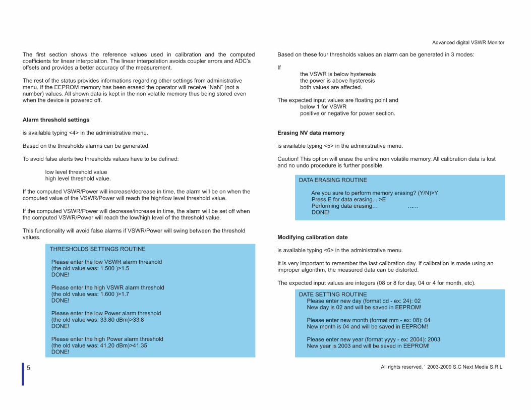
The first section shows the reference values used in calibration and the computed coefficients for linear interpolation. The linear interpolation avoids coupler errors and ADC’s offsets and provides a better accuracy of the measurement. The rest of the status provides informations regarding other settings from administrative menu. If the EEPROM memory has been erased the operator will receive “NaN” (not a number) values. All shown data is kept in the non volatile memory thus being stored even when the device is powered off. Alarm threshold settings is available typing <4> in the administrative menu. Based on the thresholds alarms can be generated. To avoid false alerts two thresholds values have to be defined:
low level threshold value high level threshold value.
If the computed VSWR/Power will increase/decrease in time, the alarm will be on when the computed value of the VSWR/Power will reach the high/low level threshold value. If the computed VSWR/Power will decrease/increase in time, the alarm will be set off when the computed VSWR/Power will reach the low/high level of the threshold value. This functionality will avoid false alarms if VSWR/Power will swing between the threshold values.
Based on these four thresholds values an alarm can be generated in 3 modes: If
the VSWR is below hysteresis the power is above hysteresis both values are affected.
The expected input values are floating point and
below 1 for VSWR positive or negative for power section.
Erasing NV data memory is available typing <5> in the administrative menu. Caution! This option will erase the entire non volatile memory. All calibration data is lost and no undo procedure is further possible. Modifying calibration date is available typing <6> in the administrative menu. It is very important to remember the last calibration day. If calibration is made using an improper algorithm, the measured data can be distorted. The expected input values are integers (08 or 8 for day, 04 or 4 for month, etc).
THRESHOLDS SETTINGS ROUTINE Please enter the low VSWR alarm threshold (the old value was: 1.500 )>1.5 DONE! Please enter the high VSWR alarm threshold (the old value was: 1.600 )>1.7 DONE! Please enter the low Power alarm threshold (the old value was: 33.80 dBm)>33.8 DONE! Please enter the high Power alarm threshold (the old value was: 41.20 dBm)>41.35 DONE!
DATA ERASING ROUTINE Are you sure to perform memory erasing? (Y/N)>Y Press E for data erasing... >E Performing data erasing… ……. DONE!
DATE SETTING ROUTINE Please enter new day (format dd - ex: 24): 02 New day is 02 and will be saved in EEPROM! Please enter new month (format mm - ex: 08): 04 New month is 04 and will be saved in EEPROM! Please enter new year (format yyyy - ex: 2004): 2003 New year is 2003 and will be saved in EEPROM!
All rights reserved. ' 2003-2009 S.C Next Media S.R.L
Advanced digital VSWR Monitor
6
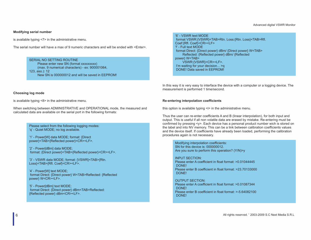
Modifying serial number is available typing <7> in the administrative menu. The serial number will have a max of 9 numeric characters and will be ended with <Enter>. Choosing log mode is available typing <8> in the administrative menu. When switching between ADMINISTRATIVE and OPERATIONAL mode, the measured and calculated data are available on the serial port in the following formats:
In this way it is very easy to interface the device with a computer or a logging device. The measurement is performed 1 time/second. Re-entering interpolation coefficients this option is available typing <i> in the administrative menu. Thus the user can re-enter coefficients A and B (linear interpolation), for both input and output. This is useful if all non volatile data are erased by mistake. Re-entering must be confirmed by pressing <y>. Each device has a personal product number wich is stored on the label and into NV memory. This can be a link between calibration coefficients values and the device itself. If coefficients have already been loaded, performing the calibration procedures again is not necessary.
SERIAL NO SETTING ROUTINE Please enter new SN (format xxxxxxxxx) (max. 9 numerical characters) - ex: 900001064, 123, aso.): 12 New SN is 000000012 and will be saved in EEPROM!
Please select from the following logging modes: ’q’ - Quiet MODE; no log available. ’1’ - Power[W] data MODE; format: {Direct power}<TAB>{Reflected power}<CR><LF>. ’2’ - Power[dBm] data MODE; format: {Direct power}<TAB>{Reflected power}<CR><LF>. ’3’ - VSWR data MODE; format: {VSWR}<TAB>{Rtn. Loss}<TAB>{Rfl. Coef}<CR><LF>. ’4’ - Power[W] text MODE; format Direct: {Direct power} W<TAB>Reflected: {Reflected power} W<CR><LF>. ’5’ - Power[dBm] text MODE; format Direct: {Direct power} dBm<TAB>Reflected: {Reflected power} dBm<CR><LF>.
’6’ - VSWR text MODE format VSWR:{VSWR}<TAB>Rtn. Loss:{Rtn. Loss}<TAB>Rfl. Coef:{Rfl. Coef}<CR><LF> ’f’ - Full text MODE format Direct: {Direct power} dBm/ {Direct power} W<TAB> Reflected: {Reflected power} dBm/ {Reflected power} W<TAB> VSWR:{VSWR}<CR><LF>. I’m waiting for your decision... >q DONE! Data saved in EEPROM!
Modifying interpolation coefficients: SN for this device is: 000000012. Are you sure to perform this operation? (Y/N)>y INPUT SECTION: Please enter A coefficient in float format: >0.01044445 DONE! Please enter B coefficient in float format: >23.70133000 DONE! OUTPUT SECTION: Please enter A coefficient in float format: >0.01087344 DONE! Please enter B coefficient in float format: >-5.64082100 DONE!
All rights reserved. ' 2003-2009 S.C Next Media S.R.L

Advanced digital VSWR Monitor
7
Choosing correction type (GSM/CDMA/PDC) this option is available typing <c> in the administrative menu. Please remember that the calibration values are assumed as refference – they are sinusoidal (CW) signal. Where a complex modulation is met, as in CDMA, GSM or PDC, the calibration of the power response needs to be adjusted accordingly. For this reason, the modulation type can be choosen by the following menu: If calibration was performed using a modulated refference signal (the same used in operating mode) choose option <0> NONE in this menu. Choosing alarm mode is available typing <a> in the administrative menu. The user can choose an alarm based on the calculated VSWR, power trend or both. This alarm is a logical one and can be NO or NC (a relay is switched based on this and is available as output on the device).
Exit Administrative routine is available typing <m> in the administrative menu. Choosing this the user switches to Operational mode, the Administrative session being close. To re-enter Administrative mode the user must perform an Init and enter the magic word as described earlier. About (hidden) is available typing <?> in the administrative menu and lists this product’s design team:
Please select from the following available modes: ’v’ - VSWR alarm; generate alarm if VSWR raise definite value. ’p’ - Power alarm; generate alarm if direct Power is under definite value. ’b’ - Both; generate alarm if one of above conditions is true. I’m waiting for your decision... >v DONE! Data saved in EEPROM!
Exiting Administrative MODE & Switch to Operational MODE..........
Supplier: (c)2004 NextMedia and Linetron IP under EES brand. Team: Hardware product designer & C programming: Andrei BUCSA C & Low level programming: Silviu PLESA RF design and RF adjustment procedures: Georgy ALBERT Marketing and datasheets: Mihai SUMEDRE * Software version 2.03 *
Choosing correction type (GSM/CDMA/PDC) the following options are available: 0 - for NONE. 1 - for GSM Channel (All Time Slots On). 2 - for CDMA Channel (Forward Link, 9 Channels On). 3 - for PDC Channel (All Time Slots On). I’m waiting for your decision... >2 DONE!
All rights reserved. ' 2003-2009 S.C Next Media S.R.L
Advanced digital VSWR Monitor
8
BiC
olo
r
Extension Conn
Gre
en
Re
d
PWR/Alarm/485
Description of the operating mode Definitions Direct wave RF signal from GSM base station being transmitted to the antenna. Reflected wave RF signal reflected through the signal path (signal path meaning the
whole path from GSM base to antenna) Power strength the power of incident and reflected wave expressed in W or dBm. VSWR Voltage Standing Wave Ratio (VSWR is a measure of impedance
mismatch between the transmission line and it’s load). Functionality The main function of the device is sending alarms when the VSWR/Power threshold is overtaking. The alarms are being sent through a NO/NC relay. The device performs real time measurement of the direct and reflected wave and computes VSWR, return loss and reflection coefficient. An intelligent measurement strategy named IntelligentSWR™ which avoids false alarms is used to accomplish maximum reliability. The second function of the device is to show online measured data using the display extension board or a computer. The measured and computed values are being displayed on a 4-lines LCD, the user having the possibility to choose between the displayed information by the <Navigation> switch; init device can also be performed using the display extension board by pressing the <Init> switch. The third function represents the capability to link into a RS485 network, view or collect and modify data through the RS232/ USB port. In operational mode special messages may be sent back by the VSWR device to the PC, if desired. These messages are formatted according to the log format options in administrative mode. The following messages are formatted in “f” mode as an example: Same data is also available on request on the RS485 bus.
Based on the measured RF parameters, the device computes following data:
VSWR of the transmission path. Return Loss Reflection Coefficient Power in dBm or W. Trend analysis of direct power and VSWR. Perform linear interpolation for measured data.
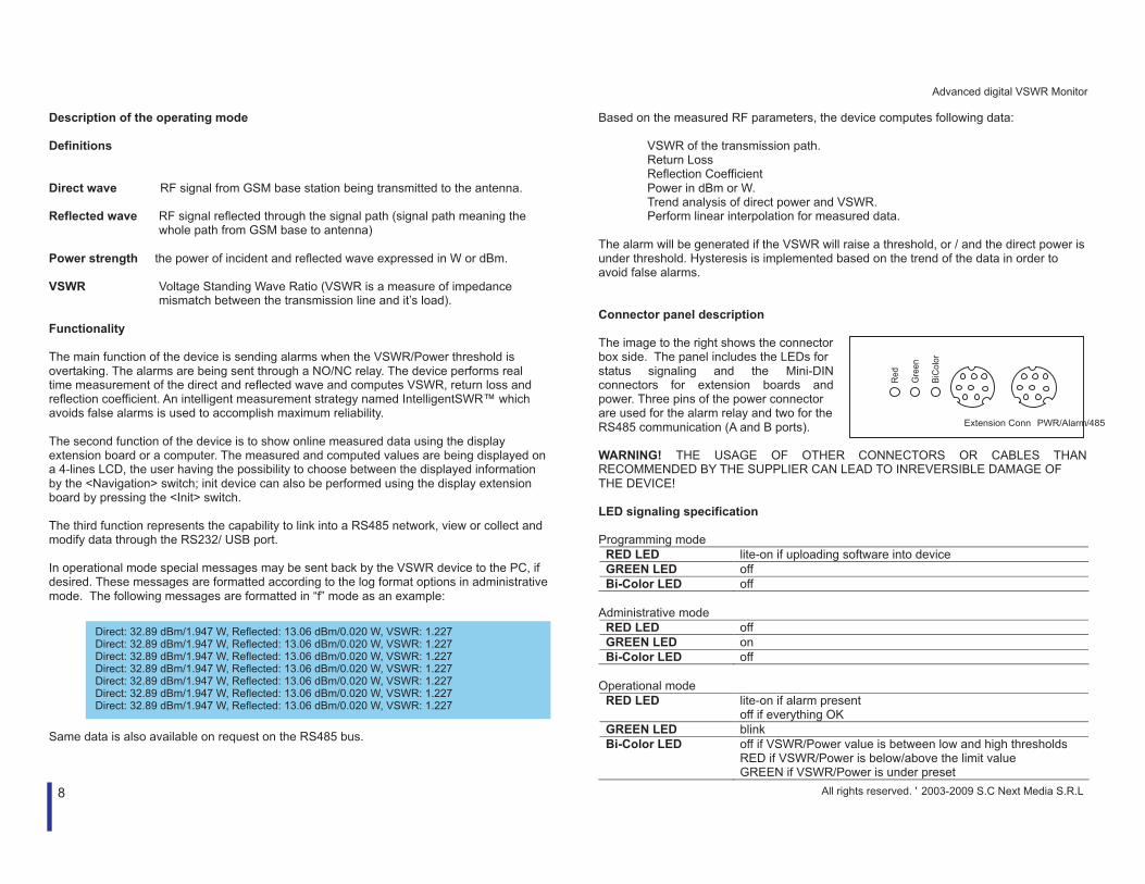
The alarm will be generated if the VSWR will raise a threshold, or / and the direct power is under threshold. Hysteresis is implemented based on the trend of the data in order to avoid false alarms. Connector panel description The image to the right shows the connector box side. The panel includes the LEDs for status signaling and the Mini-DIN connectors for extension boards and power. Three pins of the power connector are used for the alarm relay and two for the RS485 communication (A and B ports). WARNING! THE USAGE OF OTHER CONNECTORS OR CABLES THAN RECOMMENDED BY THE SUPPLIER CAN LEAD TO INREVERSIBLE DAMAGE OF THE DEVICE! LED signaling specification Programming mode
RED LED lite-on if uploading software into device GREEN LED off Bi-Color LED off
Administrative mode
RED LED off GREEN LED on Bi-Color LED off
Operational mode
RED LED lite-on if alarm present off if everything OK
GREEN LED blink Bi-Color LED off if VSWR/Power value is between low and high thresholds
RED if VSWR/Power is below/above the limit value GREEN if VSWR/Power is under preset
Direct: 32.89 dBm/1.947 W, Reflected: 13.06 dBm/0.020 W, VSWR: 1.227 Direct: 32.89 dBm/1.947 W, Reflected: 13.06 dBm/0.020 W, VSWR: 1.227 Direct: 32.89 dBm/1.947 W, Reflected: 13.06 dBm/0.020 W, VSWR: 1.227 Direct: 32.89 dBm/1.947 W, Reflected: 13.06 dBm/0.020 W, VSWR: 1.227 Direct: 32.89 dBm/1.947 W, Reflected: 13.06 dBm/0.020 W, VSWR: 1.227 Direct: 32.89 dBm/1.947 W, Reflected: 13.06 dBm/0.020 W, VSWR: 1.227 Direct: 32.89 dBm/1.947 W, Reflected: 13.06 dBm/0.020 W, VSWR: 1.227
All rights reserved. ' 2003-2009 S.C Next Media S.R.L
Advanced digital VSWR Monitor
9
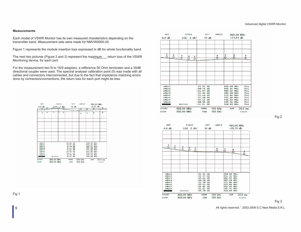
Measurements Each model of VSWR Monitor has its own measured charateristics depending on the transmitter band. Measurement sets were made for NMVW0900-20. Figure 1 represents the module insertion loss expressed in dB for whole functionality band. The next two pictures (Figure 2 and 3) represent the maximum return loss of the VSWR Monitoring device, for each port. For the measurement two N to 16/9 adapters, a refference 50 Ohm terminator and a 30dB directional coupler were used. The spectral analyser calibration point (0) was made with all cables and connectors interconnected, but due to the fact that impedance matching errors done by connectors/connections, the return loss for each port might be less.
Fig 1
Fig 2
Fig 3
All rights reserved. ' 2003-2009 S.C Next Media S.R.L

Advanced digital VSWR Monitor
10
Accessories available Power supply features
8.6V out 100-250V or 12-60V input switching source supply power for up to 8 devices 8 alarm NO/NC output USB/RS232 Host connector (optional) DATA display (optional) 1U rack mount type
Display expansion board features
plug-and-play and hot-pluggable 4-row / 16-characters LCD module Init Switch Navigation Switch Programming switch
PC cable features
plug-and-play and hot-pluggable Standard RS232 or USB cable connector Maximum speed 115K/s (RS232) or 230K/s (USB) Administrative switch
micro MMC (FAT16™) card logging extension
plug-and-play and hot-pluggable MMC card connector Real time clock Self powered from VSWR monitor Up to 128Mb log memory
Display expansion The display extension provides informtaion of the measured and computed parameters without the need of a computer. Characteristics
plug-and-play and hot-pluggable designed to work in the industrial temperature range
Providing power is connected, the display extension will be autodetected by pressing the <init> button. The <Navigate> button provides the following five pages of information, displayed on LCD. Keeping the <Navigate> button pressed will select the current information page.
page 1 page 3
page 2 page 4
page 5
The data displayed has the following meaning:
Data Meaning Direct Direct power from transmitting equipment (in dBm or W) Reflected Reflected power from the antenna or RF path (in dBm or W) VSWR Value of Voltage Standing Wave Ratio Rtn. Loss Return loss (value in dB) Rfl. Coef Reflection coefficient Power Lth Power Low Threshold (used for alarms) Power Hth Power High Threshold (used for alarms) VSWR L/H Low and High thresholds for VSWR alarms Alarm Alarm mode (VSWR, Power or Both) SN Serial Number of the device Device Temp Die Temp of the processor (Celsius degrees)
900 MHz VSWR Monitor Direct: 35.265 dBm Reflected: 18.725 dBm VSWR: 1.35 (OK)
900 MHz VSWR Monitor Direct: 15.326 W Reflected: 4.485 W VSWR: 3.39 (FAIL)
900 MHz VSWR Monitor Rtn. Loss: 19.80 dB Rfl. Coef: 0.102 VSWR: 1.228
900 MHz VSWR Monitor Power Lth: 33.80 Power Hth: 34.00 VSWR L/H: 1.36/1.38
900 MHz VSWR Monitor Alarm: VSWR. SN: 000000001. Device Temp: 36.4 °C
All rights reserved. ' 2003-2009 S.C Next Media S.R.L

Advanced digital VSWR Monitor
11
Firmware uploading is possible using the display extension and the PC cable extension. Uploading firmware is performed with the supplied PC tool by switching the <Program> button and shortly pressing the <Init> button. The parameters for the uploading procedure are 9600 baud, 8, N, 1. WARNING! MAKE SURE THAT ALL APPLICATIONS USING COM PORTS ARE CLOSED WHEN UPLOADING NEW FIRMWARE. SET THE PC TOOL TO ERASE ONLY CODE. OTHERWISE ALL CALIBRATION DATA WILL BE LOST. PC cable extension The PC cable extension comes in two variants:
RS232 cable USB cable
Both types of cable have an <Init> button. This is used to enter the administrative mode. Connect the cable to the VSWR monitor then shortly press the <Init> button on the DB9 connector. Switching back to operating mode or logging mode is done by
pressing <enter> when the device asks for the magic word, or typing <m> in the administrative menu
When using both extensions (display and PC cable), the display extension will be connected to the VSWR monitor and the PC cable to the display extension. In this case, only the display procedure will lead to entering the administrative mode. Power supply extension is used to provide power for up to 12 VSWR monitor modules. Power can be used either from the
transmitter backup batteries (12-60V), or direct tripple-phased 220V network
The power extension also provides up to 12 NO, NC connectors, as alarm output.
Upon special request the module can be upgraded to supervise all connected VSWR monitors. All data will be awailable on one LCD display. An USB/RS232 connector for PC connection will be provided as well as a microMMC card logging extension. micro MMC (FAT16™) card logging extension is used to store logging files tinto a MMC card using the FAT16 format. All programing options are available through the terminal. The extension contains a real-time clock and includes formatting and MMC file management procedures.
All rights reserved. ' 2003-2009 S.C Next Media S.R.L
Advanced digital VSWR Monitor
12
VSWR monitor characteristics
NMVW0900-20 EGSM900 (880Mhz-960MHz)
NMVW1800-20 DCS1800 (1710MHz-1880MHz)
NMVW1900-20 PCS1900 (1850MHz-1990MHz) Product code Frequency Range
NMVW0450-20 CDMA2000 (450MHz band)
Power Measurement Range 15W to 65W Maximum input power Pw [peak] 150W Maximum Insertion Loss 0.6dB (into whole band) VSWR range 1.22:1 to 1.92:1 Relay contact type NO/NC Contact rating 250V /0.5A Visual 3 LEDs: 1-GREEN, 1-RED, 1-BiCOLOR Stimulus VSWR threshold exceed and/or
Under power operation
Reset Init button on LCD extension
Under voltage operation Temperature exceeding
Interface to host type RS232/RS485 and USB Protocol Serial asynchronous, 38400 baud, 8, N, 1/ 9600, 8,
N, 1 for uploading firmware RF Connector 7/16 Male for input
7/16 Female for output Operating Temperature -10 – 50 °C Storage Temperature -25 – 80 °C Humidity Max 80%, non-condensing Altitude Up to 3500m above sea level Power requirements +8.5V-12V or 9V-40V Dimensions (WxHxL mm) excluding connectors
71.9 x 32.3 x 108.0
Weight 605 gr
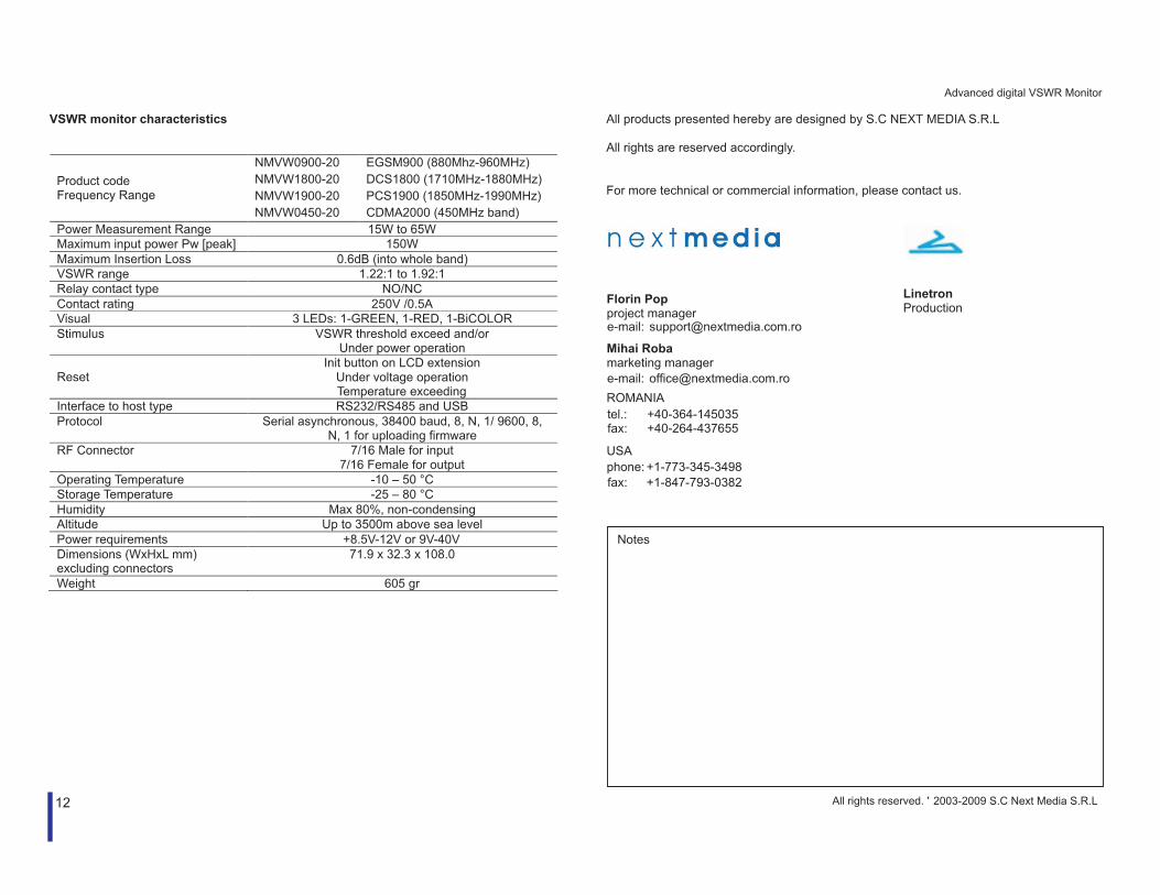
All products presented hereby are designed by S.C NEXT MEDIA S.R.L All rights are reserved accordingly. For more technical or commercial information, please contact us.
Linetron Production
Notes
All rights reserved. ' 2003-2009 S.C Next Media S.R.L
Florin Pop project manager
tel.: +40-364-145035fax: +40-264-437655
e-mail: [email protected]
Mihai Robamarketing manager
phone: +1-773-345-3498
fax: +1-847-793-0382
e-mail: [email protected] ROMANIA
USA