for gravity flow pipes in buildings - preis group · for gravity flow pipes in ... and design as of...
TRANSCRIPT

fp p
reis
® sm
l -
tech
nic
al s
peci
fica
tio
ns
ww
w.p
reis
grou
p.co
m
Technical Specifi cations for Gravity Flow Pipes in Buildings

Tabl
e of
Con
tent
s
02__
Technical manual for gravity fl ow pipes in buildingsThis documentation is intended to give an overview about the most important regulations for planning and design as of EN 12056:2000 including installation instructions. This documentation shall provide information and does not claim to be complete. For detailed information about assembling and design, please, refer to the corresponding national standards and regulations.
FPPREISSML

1 General requirements 04
1.1 Drainage systems 05
1.2 Filling level 05
2 Connection pipes 06
2.1 Calculation of the wastewater evacuation 06
2.2 Runoff coefficient 06
2.3 Design units (DU) 06
2.4 Calculation table for wastewater evacuation 06
2.5 Connection pipes 06
2.5.1 Vented connection pipes 07
2.5.2 Non-vented connection pipes 08
3 Downpipes 08
3.1 General remarks 08
3.1.1 Reaction forces 093.1.2 Pressure fl ow in downpipes 103.1.3 Flow velocity 1 13.1.4 Defl ection of downpipes in multi-storey-buildings 12
3.2 Downpipes for wastewater 13
3.2.1 Determination of the downpipe length 13
3.2.2 Choosing a venting system 14
3.2.2.1 Wastewater gravity fl ow pipe with main ventilation 14
3.2.2.2 Wastewater gravity fl ow pipe with direct secondary ventilation 14
3.2.2.3 Wastewater gravity fl ow pipe with indirect secondary ventilation 15
3.3 Gravity drainage pipe for rainwater 15
3.3.1 Roof surfaces with big differences in height 17
4 Base pipes and collective pipes 17
5 Wall and ceiling pass-throughs 18
6 Wastewater lifting systems 19
7 Fixings 21
8 Cutting 22
9 Couplings 23
9.1 Installation instructions 23
9.2 Regulations for pipe laying and maximum pressure admissible for couplings 25
9.3 Securing rainwater downpipes 25
10 Pipes embedded in concrete 25
11 Calculation example 26
Table of Contents
Tabl
e of
Con
tent
s
__03
Table of Contents
FPPREISSML

Tech
nica
l det
ails
GEN
ERA
L RE
QU
IREM
ENTS
04__
For proper functioning of drainage systems the following general requirements have to be fulfi lled:
1. Wastewater has to be discharged providing quiet operation.
2. Self-cleansing properties of the drainage system have to be ensured.
3. Evacuation of the maximum wastewater volume to be expected has to be guaranteed.
4. Pressure fl uctuations have to be inhibited as they could cause seal water to be drawn out from the traps or cause backfl ow into the tubes of sanitary equipment to be drained.
5. The required venting capacity of the drainage system has to be ensured by taking proper venting measures and by partial fi lling of the tubes.
6. Resistance of the tubes and fi ttings against effects of the sewage.
7. Drainage systems have to provide suffi cient measures to be water tight and gas-tight under working pressure. It has to be guaranteed that pipe systems in buildings do not allow foul air or bad odours to spread in the building.
As a basic condition, conventional drainage using gravity fl ow lines requires a suffi cient fi lling level and a mid-range fl ow rate in order to ensure suspended particles and deposited matter to be properly transported and fl ushed out.The proper hydraulic functioning is given if the fl ow in partially fi lled tubes is unchanging and steady.
General requirements1
single pipe connections collective connection pipes
downpipes / venting pipes
base pipescollective pipes
Basically, it can be differentiated between:
Picture 01 Types of pipes
FPPREISSML

Tech
nica
l det
ails
GEN
ERA
L RE
QU
IREM
ENTS
__05
General remarksThere is a widespread range of drainage systems; this is due to the different kinds of applications and the varying sanitary facilities in the respective countries and due to most various technical layouts.
Types of systemsAs a general rule, drainage systems may be divided into 4 different groups, although there are slight varia-tions within each type (therefore, it is necessary to refer to the requirements given by national and regional regulations and to the technical specifi cations). As in practice system I and system II types are the most com-mon ones, the following details refer only to these types.
System I - single downpipe system with partially fi lled connection pipesSanitary facilities to be drained are connected to partially fi lled connection pipes. The partially fi lled connection pipes are designed for a fi lling level of 0.5 (50%) and they are connected to a single wastewater downpipe.
System II - single downpipe with connection pipes of smaller diameters.Sanitary facilities are connected to connection pipes with a smaller diameter. The connection pipes with a smaller diameter dispose of a fi lling level of 0.7 (70%) and they are connected to a single wastewater downpipe.
Filling level in horizontal wastewater pipes refers to the ratio of depth of water to the inner diameter. In the case of downpipes the fi lling level refers to the ratio between the cross section of the pipe fi lled with water and the total cross section.
1.1
1.2
Drainage systems classifi ed in accordance with EN 12056
Filling level
inner surface of the pipe
water jacket
air core
Sectional graph: B-B
A
B
A
B
free space for air expansion
Sectional graph: A-A
dih
Picture 02 Formation of water jackets and
air cores in downpipes behind a branch
Horizontal pipe Downpipe
In general in both systems has to be observed that the cross section of the piping system in fl ow direction may never be reduced.
FPPREISSML

06__
Qww refers to the expected drain of wastewater in these parts of the whole drainage system, where only sanitary facilities are connected to the system.
Table 01 shows typical values for the runoff coeffi cient in association with the frequency of use of the sani-tary facilities.
Table 02 shows the values for various sanitary facilities to be drained. The values shown are only valid for calcu-lation of the system and do not relate to design units of sanitary facilities as included in product standards.
Connection pipes2
2.2
2.3
2.1 Calculation of the wastewater drain (Qww)
Runoff coeffi cient (K)
Design units (DU)
DUQww = KQww = wastewater drain (l per sec.)
K = runoff coeffi cient
= sum of the design units
T Y P I C A L V A L U E S F O R R U N O F F C O E F F I C I E N T ( K )
Type of building KIrregular use. e.g. in residential buildings. boarding houses. offices 0.5Regular use, e.g. in hospitals, schools, restaurants, hotels 0.7Frequent use, e.g. in public restrooms and / or showers 1.0Special use, e.g. laboratories 1.2
Facility to drainSystem I System II
DU (l/s) DU (l/s)
Hand basin. bidet 0.5 0.3
Shower without plug 0.6 0.4
Shower with plug 0.8 0.5
Individual urinal with cistern 0.8 0.5
Urinal pressurized flush 0.5 0.3
Floor stand urinal 0.2* 0.2*
Bathtub 0.8 0.6
Kitchen sink 0.8 0.6
Dishwasher (household) 0.8 0.6
D E S I G N U N I T S ( D U )
Facility to drainSystem I System II
DU (l/s) DU (l/s)
Washing machine. capacity ≥ 6 kg 0.8 0.6
Washing machine, capacity ≥ 12 kg 1.5 1.2
Toilet with cistern, volume 4.0 l ** 1.8
Toilet with cistern, volume 6.0 l 2.0 1.8
Toilet with cistern, volume 7.5 l 2.0 1.8
Toilet with cistern, volume 9.0 l 2.5 2.0
Floor drain DN 50 0.8 0.9
Floor drain DN 70 1.5 0.9
Floor drain DN 100 2.0 1.2
* per person ** not approved
Table 01
Table 02
The values have been calculated with the following equation: DUQww = K
2.4 Calculation table for wastewater evacuation
Tech
nica
l det
ails
CON
NEC
TIO
N P
IPES
FPPREISSML

__07
Tech
nica
l det
ails
CON
NEC
TIO
N P
IPES
2.5 Connection pipes
Nominal width and restrictions of their application can be seen in tables 04 and 05. Restrictions of appli-cation as referred to in table 05 are simplifications; for further information, please, refer to national and regional regulations.
2.5.1 Vented Connection Pipes
ADMISSI BLE WASTEWATER DRAI N AN D NOMI NAL WI DTH
Qmax (l/s)
System I System II
DN DN
Connection / Venting
Connection / Venting
0.60 * 30/30
0.75 50/40 40/30
1.50 60/40 50/30
2.25 70/50 60/30
3.00 80/50** 70/40
3.40 90/60*** 80/40**
3.75 100/60 90/50
RESTRICTIONS OF APPLICATION
Restrictions of Application System I System II
max. pipe length (L) 10.0m no limit
max. number of bends 90° no limit no limit
max. flow distance (H) with a bend of 45° or more
3.0m 3.0m
minimum gradient 0.5% 0.5%
* not permitted ** no toilets *** maximum 2 toilets and vertical turn of 90° not allowed
* bend connection not included
1 connection bend 2 downpipe 3 connection pipe 4 venting pipe
L
H
1 2
34Picture 03 Application restrictions of vented connection pipes in system I and II types
Table 04 Table 05
Total of the design units
K0.5
K0.7
K1.0
K1.2
Qww(l/s)
Qww(l/s)
Qww(l/s)
Qww(l/s)
10 1.6 2.2 3.2 3.8
12 1.7 2.4 3.5 4.3
14 1.9 2.6 3.7 4.5
16 2.0 2.8 4.0 4.8
18 2.1 3.0 4.2 5.1
20 2.2 3.1 4.5 5.4
25 2.5 3.5 5.0 6.0
30 2.7 3.8 5.5 6.6
35 3.0 4.1 5.9 7.1
40 3.2 4.4 6.3 7.6
45 3.4 4.7 6.7 8.0
50 3.5 4.9 7.1 8.5
60 3.9 5.4 7.7 9.3
70 4.2 5.9 8.4 10.0
80 4.5 6.6 8.9 10.7
90 4.7 6.6 9.5 11.4
100 5.0 7.0 10.0 12.0
110 5.2 7.3 10.5 12.6
120 5.5 7.7 11.0 13.1
Total of the design units
K0,5
K0,7
K1,0
K1,2
Qww(l/s)
Qww(l/s)
Qww(l/s)
Qww(l/s)
130 5.7 8.0 11.4 13.7
140 5.9 8.3 11.8 14.2
150 6.1 8.6 12.2 14.7
160 6.3 8.9 12.6 15.2
170 6.5 9.1 13.0 15.6
180 6.7 9.4 13.4 16.1
190 6.9 9.6 13.8 16.5
200 7.4 9.9 14.1 17.0
220 7.6 10.4 14.8 17.8
240 7.7 10.8 15.5 18.6
260 8.1 11.3 16.1 19.3
280 8.4 11.7 16.7 20.1
300 8.7 12.1 17.3 20.8
320 8.9 12.5 17.9 21.5
340 9.2 12.9 18.4 22.1
360 9.5 13.3 19.0 22.8
380 9.7 13.6 19.5 23.4
400 10.0 14.0 20.0 24.0
420 10.2 14.3 20.5 24.6
W A S T E W A T E R E V A C U A T I O N (Qww)Table 03
FPPREISSML

08__
Tech
nica
l det
ails
DO
WN
PIPE
S .
CO
NN
ECTI
ON
PIP
ES
A downpipe is to be understood as a vertical pipe, leading through one or more storeys, with venting carried out via the roof.
Tip: In order to guarantee proper ventilation of the downpipe, the pipe has to be dimensioned according to the amount of water gathering at the lowest point. Hence, the whole downpipe has to be dimensioned according to this value and it must not be reduced to-wards the top.
Downpipes3
3.1 General remarks
Picture 05 Picture 06
RESTRICTIONS OF APPLICATION
Restrictions of Application System I System II
max. pipe length (L) 4.0m 10.0m
max. number of bends 90° 3* 1*
max. fl ow distance (H) with a bend of 45° or more
1.0m**6.0m DN ›70**3.0m DN =70
minimum gradient 1% 1.5%
ADMISSI BLE WASTEWATER DRAI N AN D NOMI NAL WI DTH
Qmax (l/s)
System I System II
DN DN
Connection Connection
0.40 * 30
0.50 40 40
0.80 50 *
1.00 60 50
1.50 70 60
2.00 80** 70**
2.25 90*** 80****
2.50 100 90* not permitted ** no toilets *** maximum 2 toilets and vertical turning of 90° not allowed **** maximum 1 toilet
* bend connection not included** If DN is smaller than 100 mm and a toilet is connected to a non-vented connec-tion pipe, connection to a vented system of another facility to be drained within a distance of 1 m is not allowed.
Tables 06 and 07 show nominal width and application restrictions of non-vented connection pipes. Wherever application restrictions cannot be kept, non-vented connection pipes have to be vented, unless otherwise specifi ed in national or regional regulations, thus, allowing bigger nominal widths or installation of venting valves. The restrictions of application as referred to in table 07 are simplifi cations; for further information, please, refer to national and regional regulations.
2.5.2 Non-vented connection pipes
L
H
1 2
3
1 connection bend 2 downpipe 3 connection pipe
Picture 04 Application restrictions of vented connection pipes, systems I and II
Table 06 Table 07
FPPREISSML
DN 10
0DN
100
Picture 06
DN 10
0DN
50
DN 10
0
Picture 06
DN 5
0
Picture 05
DN 10
0
Picture 06
DN 10
0DN
100
DN 10
0DN
50

__09
Reaction forces at turnsAt the transition from a downpipe to a horizontal pipe notable reaction forces might occur due to the deviation of fl ow. Hence, special attention has to be paid to rain water downpipes and downpipes with a high water column. When selecting couplings, it has to be observed that the expected pressure load does not exceed the values stipulated in the manufacturer’s specifi cations. The following example illustrates the reaction forces set free in a turn of 90°.
Fx = Fy = p * Ax * vx2 + px * Ax
whereas p = refers to the density of water [kg/m3]Ax = refers to the area of cross section of stream [m2]vx = refers to the fl ow velocity of the stream [m/s]px = refers to the static interior pressure of the stream surface [pascal]
The resulting force, therefore, is as follows:
whereasFres = refers to the resulting force from Fx plusFy (this is the force that acts in pipe connections)
Examples of calculations for DN 100 and DN 150 with px = 0,5 bar und vx = 7,0 m/s.
Example 1: Fres DN 100 = 1,098.80 N = 112 kgExample 2: Fres DN 150 = 2,472.29 N = 252 kg
Calculations for example 2:
Fx = Fy = 998.50 * 0,02 * 49.00 + 50,000.00 * 0,02 = 1,748.18
Fres = 1,748.182 + 1,748.182 = 2,472.29 N (corresponds approx. to 252 kg)
3.1.1 Reaction forces
Fres = Fx2 + Fy2
Findings: Forces acting at constant internal pressure and identical velocity increase disproportio-nate to the diameter of the pipe. For measures against slipping of the couplings (axial restraint) see chapter “Couplings”, page 23.
Tech
nica
l det
ails
DO
WN
PIPE
S
Picture 07 Forces active in a turn of 90° (downpipe into horizontal pipe) under high pressure (gravity fl ow drainage)
FPPREISSML
Fy
Fx
Fres
DN 10
0DN
100 Findings:
nate to the diameter of the pipe. For measures against slipping of the couplings (axial restraint) see chapter “Couplings”, page 23.

10__
Tech
nica
l det
ails
DO
WN
PIPE
S
Downpipes have to take over ventilation tasks, as horizontal wastewater pipes do. Downpipes in operation are only partially fi lled, but we have to assume that the areas fi lled with air or water cannot be defi ned as clearly as this can be done in horizontal lines (see picture 02). In order to ensure an unhindered air circulation, at least one main ventilation has to be planned in downpipes. A steady fl ow is hard to reach due to the interactions of wastewater and air; as a result, pressure fl uctuations in downpipes may occur. These fl uctuations have a critical impact on odour traps. It has to be observed that the height of the odour trap / seal water (H) must remain over 50 mm, even when seal water is drawn out of the traps due to pressure fl uctuations.
The connection selected has a substantial infl uence on pressure fl uctuations in downpipes and therefore on the hydraulic load. ATTENTION: Beside the volume of wastewater, the cross section of the pipe and the axial restraint, above all the branch layout in the downpipe is of critical importance. At the connection pipe air has to circulate above the water to be drained (see picture 10). In the downpipe the infl owing water should not cover the whole cross section of the pipe. Otherwise, there would be a hydraulic closure accompanied by a high pressure drop (see picture 11).It is recommended to use branches with 88.5° when connecting them to downpipes, as branches with 45° could cause a hydraulic closure, which, as a consequence, could lead to a self-suction of the connected odour trap.
Optimum discharge is reached with a branch of 88.5° and an access angle of 45°. These types of branches, best for optimum hydraulic conditions according to EN 12056, allow 30% more load than common branches.As a standard, all FP PREIS® SML branches are designed with the optimum access angle of 45°.
3.1.2 Pressure fl ow in downpipes
H
Maximum static pressure in mbar
16
14
12
10
8
6
4
2 m
4 3 2 1 0 1 2 3
(—) (+)
Picture 09 Pressure fl uctuation in a wastewater downpipe
Picture 10 Picture 11
Picture 08 Odour trap
45°
FPPREISSML

__11
It was found that for proper operation of a downpipe considerable air volume streams are necessary. To give an example, in a downpipe size DN 100 carrying a wastewater volume of 100 l per minute, a total of 2,340 l per minute passes through.Due to the great number of different variables the possible load of downpipes can only be calculated in a very rough way. To optimize the functions, we recommend the following layout:
Flow velocity of wastewater in downpipesEvacuation in downpipes occurs as shown in picture 02; after a short free fall the water forms a water jacket along the wall of the pipe and in the middle of the pipe an air core is formed. The fl ow is slowed down by the resistance of the air column in the pipe and the friction at the pipe walls. In vacuum, the fl ow velocity of the wastewater would be speeded up with the fall height accelerated by the acceleration of the fall V=9.81 m/s2. The following equation applies: V= 2gh (= m per sec.). Measurements have shown that fl ow acceleration and decelerating by the air column and pipe friction neutralize at a distance of about 15 metres, so that a maximum fl ow velocity of 10 m per second is reached to remain stable at this value.Hence, an additional slow down of the fl ow in downpipes of multi-storey-buildings in the form of additional pipe defl ections is not necessary.
3.1.3 Flow velocity
b
c
a) free fall in vacuum
b) fully fi lled pipe
c) with water jacket and air core
Velo
city
m/s
25
20
15
10
5
0 5 10 1 5 20 25 30 35m
a
b
c
Fall height
Tech
nica
l det
ails
DO
WN
PIPE
S
Picture 12 Theoretical and actual fl ow velocity in downpipes
• Connection of branches with an access angle of 45°• As a best case scenario nominal width of the connection pipe should be smaller than the nominal width of the downpipe • To keep the loss of fl ow as low as possible, the venting pipes should be kept as short and straight as possible
FPPREISSML

12__
The following two infl uencing factors have a deci-sive impact on the pressure load in downpipes:
• Infl ow conditions at the connection pipes
• Defl ection of wastewater fl ow
Every downpipe disposes of at least one defl ection in the area of transition into the collective pipe or the base pipes. As a general rule, defl ections of downpipes should be avoided, unless structural conditions do not allow a fully vertical pipe. Dynamic pressure develops when the water jacket and the air core of the wastewater to drain arrive at a defl ection. Flow velocity will slow down, the volume of the water in the pipe will increase and the air volume is compressed, provided that the air cannot escape. This leads to a pressure increase in this section of the tube; hence, it is not possible to directly connect a facility to drain in this section of overpressure.
In order to be able to still connect facilities to be drained in this area, a bypass pipe has to be built. In the area where overpressure develops, an additional pipe is installed which runs parallel to the defl ection.
3.1.4 Defl ection of downpipes in multi-storey-buildings
Picture 13 Defl ection of downpipes < 2m with bypass pipe
In case of a defl ection or the transition of a down-pipe into a horizontal pipe a bypass pipe has to be installed if downpipes are longer than 22 m. If the defl ection of the pipe is less than 2 m, picture 13 applies, if it is more than 2 m or there is a transition into a horizontal pipe, refer to picture 14 for layout.
1 m m
in.
2 m
min
.
< 2 m
Tech
nica
l det
ails
DO
WN
PIPE
SFPPREISSML
__13
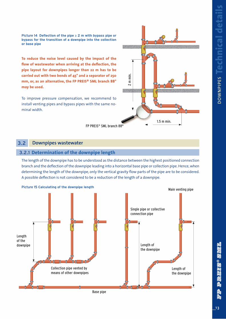
To reduce the noise level caused by the impact of the fl ow of wastewater when arriving at the defl ection, the pipe layout for downpipes longer than 22 m has to be carried out with two bends of 45° and a separator of 250 mm, or, as an alternative, the FP PREIS® SML branch 88° may be used.
To improve pressure compensation, we recommend to install venting pipes and bypass pipes with the same no-minal width.
2 m
min
.
1.5 m min.
Picture 14 Defl ection of the pipe ≥ 2 m with bypass pipe or bypass for the transition of a downpipe into the collection or base pipe
Picture 15 Calculating of the downpipe length
The length of the downpipe has to be understood as the distance between the highest positioned connection branch and the defl ection of the downpipe leading into a horizontal base pipe or collection pipe. Hence, when determining the length of the downpipe, only the vertical gravity fl ow parts of the pipe are to be considered. A possible defl ection is not considered to be a reduction of the length of a downpipe.
3.2 Downpipes wastewater
3.2.1 Determination of the downpipe length
Main venting pipe
Single pipe or collective connection pipe
Length of the downpipe
Length of the downpipe
Length of the downpipe
Collection pipe vented by means of other downpipes
Base pipe
FP PREIS® SML branch 88°
Tech
nica
l det
ails
DO
WN
PIPE
SFPPREISSML

14__
3.2.2 Choosing a venting system
3.2.2.1 Wastewater gravity fl ow pipe with main ventilation
3.2.2.2 Wastewater gravity fl ow pipe with indirect secondary ventilation
Venting pipes are designed to control and limit pressure fl uctuations within the drainage system. As a general rule the following venting systems are applied:
• main ventilation• direct secondary ventilation• indirect secondary ventilation
A main ventilation pipe is a pipe where one or more downpipes are integrated having a ventilation opening at the roof. Wastewater downpipes with main ventilation have to be designed according to table 08.
In a secondary ventilation system the strain of venti-lation of the downpipe is reduced by a parallel ventilation pipe which is connected to the downpipe at every storey. This system leads to a notable increase of wastewater evacuation compared to the system with main ventilation. This ventilation system is especially suitable for gravity fl ow lines with short individual evacuation pipes or collection pipes.
M A X . WASTEWATE R EVAC UATI O N A DM I S S I B L E (Qmax) A N D N O M I N A L W I DT H ( D N )
Wastewater gravity fl ow pipe with main ventilation
System I. IIQmax (l/s)
DN Branches Branches with access angle 45°
70 1.5 2.0
80* 2.0 2.6
100** 4.0 5.2
125 5.8 7.6
150 9.5 12.4
200 16.0 21.0
*minimum nominal width for connections of toilets to system II **minimum nominal width for connections of toilets to system I
Main ventilationdirect secondary ventilation
Table 08
Picture 16 direct secondary ventilation
Tech
nica
l det
ails
DO
WN
PIPE
SFPPREISSML

__15
Indirect secondary ventilation is car-ried out by an additional ventilation pipe which either leads directly to the roof, being connected to the up-per end of a connection pipe or which is connected to the main ventilation pipe. The maximum evacuation, thus, is notably higher than in the conven-tional main ventilation system.
3.2.2.3 Wastewater gravity flow pipes with indirect secondary ventilation
indirect secondary ventilation
Inspection opening at the end of the highly loaded
collective connection pipe.
MAX. WASTEWATER EVACUATION ADMISSIBLE (Qmax) AND NOMINAL WIDTH ( D N )
Wastewater gravity flow pipe with main ventilation
indirect secondary ventilation
System I. IIQmax (l/s)
DN DN Branches Branches with access angle 45°
70 50 2.0 2.6
80* 50 2.6 3.4
100** 50 5.6 7.3
125 70 8.4 10.9
150 80 14.1 18.3
200 100 21.0 27.3
*minimum nominal width for connections of toilets to system II **minimum nominal width for connections of toilets to system I
3.3 Gravity drainage pipes for rainwater
Item 6.1 of EN 12056-3 contains the following: “The maximum discharge of rainwater in vertical gravity flow pipes with circular cross section should not surpass the value indicated in table 10. The value for the filling level of 0.33 has to be applied, unless otherwise stated in national, regional or technical regulations, setting a value between 0.20 and 0.33.Moreover, internal rainwater pipes shall be able to withstand the head of water likely to occur in case of clogging.
Table 09
Picture 17 indirect secondary ventilation
Tech
nica
l det
ails
DO
WN
PIPE
SFPPREISSML

16__
R A I N WAT E R E VA C UAT I O N W I T H G R AV I T Y D R A I N A G E P I P E S M A D E B Y F P P R E I S ® S M L
DNMinimum external
diameterin mm
Wall thicknessin mm
Minimum inner diameter
in mm
Filling level
0.20 0.33
50 57.0 3.50 50.0 0,7 l/s 1,7 l/s
70 77.0 3.50 70.0 1,8 l/s 4,2 l/s
80 82.0 3.50 75.0 2,2 l/s 5,1 l/s
100 109.0 3.50 102.0 4,9 l/s 11,5 l/s
125 133.0 4.00 125.0 8,4 l/s 19,8 l/s
150 158.0 4.00 150.0 13,7 l/s 32,1 l/s
200 207.5 5.00 197.5 28,5 l/s 66,9 l/s
250 271.5 5.50 260.5 59,7 l/s 140,0 l/s
300 323.5 6.00 311.5 96,2 l/s 225,5 l/s
* as a calculation basis the minimum inner diameter according to EN 877 has been chosen. Maximum sized pipes have an accordingly higher drainage performance, which can be calculated applying the WYLY EATON equation.
If it is necessary to integrate a deflection, 2 different versions may be designed, according to the measures of the angle:
• If the angle is < 10° to the horizontal, the pipe has to be dimensioned like a base pipe or a collective pipe (see picture 18).
• If the angle is > 10° to the horizontal, the pipe has to be dimensioned like a gravity drainage rainwater pipe (see picture 19).
Influence of a deflection of the gravity drainage rainwater pipe
Table 10
Picture 18 Picture 19
Tip: Condensate may develop due to high temperature differences between the liquids to be discharged and the material of the pipes. At all sections where condensate in rainwater drainage pipes might form, internal pipes of buildings are to be insulated in an appropriate way.
Due to the predefined filling level of 0.20 to 0.33, adequate ventilation is given, so that pressure compensa-tion is always possible and, thus, it is not necessary to install additional venting pipes.
Tech
nica
l det
ails
DO
WN
PIPE
SFPPREISSML

3.3.1 Roof surfaces with big differences in height
It is recommended, to drain roofs with big dif-ferences in height by means of separate down-pipes, as a collective pipe may lead to fl ooding of the base surface of the roof in case of heavy rainfalls or clogging.
__17
Picture 20 Roofs with big height differences
Base pipes and collective pipes4
In general, we can decide between two kinds of pipes: Base pipe ¬ Drainage pipes within the building, embedded in foundations or laid below foundations (e.g. embedded in concrete), or sanitary facilities directly connected to downpipes or connected at the basement.
Collective pipe ¬ Horizontal pipe, in general laid below the basement ceiling, to receive wastewater from downpipes and connection pipes.
For inspection or cleaning of the pipes and easier modernization of the system, the preferred option should be to install collective pipes. In both types of pipes special attention should be paid to providing them with suffi cient cleaning facili-ties.Base pipes and collective pipes are calculated applying the Prandtl-Colebrook equation. The layout may be calculated according to the following tables:
Tech
nica
l det
ails
DO
WN
PIPE
S .
BA
SE P
IPES
AN
D C
OLL
ECTI
VE
PIPE
SFPPREISSML

18__
Tech
nica
l det
ails
BASE
PIP
ES A
ND
CO
LLEC
TIV
E PI
PES
Gradient DN 100 DN 125 DN 150 DN 200 DN 250 DN 300
i Qmax V Qmax V Qmax V Qmax V Qmax V Qmax V
cm/m l/s m/s l/s m/s l/s m/s l/s m/s l/s m/s l/s m/s
0.50 1.8 0.5 2.8 0.5 5.4 0.6 10.0 0.8 18.9 0.9 34.1 1.0
1.00 2.5 0.7 4.1 0.8 7.7 0.9 14.2 1.1 26.9 1.2 48.3 1.4
1.50 3.1 0.8 5.0 1.0 9.4 1.1 17.4 1.3 32.9 1.5 59.2 1.8
2.00 3.5 1.0 5.7 1.1 10.9 1.3 20.1 1.5 38.1 1.8 68.4 2.0
2.50 4.0 1.1 6.4 1.2 12.2 1.5 22.5 1.7 42.6 2.0 76.6 2.3
3.00 4.4 1.2 7.1 1.4 13.3 1.6 24.7 1.9 46.7 2.2 83.9 2.5
3.50 4.7 1.3 7.6 1.5 14.4 1.7 26.6 2.0 50.4 2.3 90.7 2.7
4.00 5.0 1.4 8.2 1.6 15.4 1.8 28.5 2.1 53.9 2.5 96.9 2.9
4.50 5.3 1.5 8.7 1.7 16.3 2.0 30.2 2.3 57.3 2.7 102.8 3.1
5.00 5.6 1.6 9.1 1.8 17.2 2.1 31.9 2.4 60.3 2.8 108.4 3.2
Gradient DN 100 DN 125 DN 150 DN 200 DN 250 DN 300
i Qmax V Qmax V Qmax V Qmax V Qmax V Qmax V
cm/m l/s m/s l/s m/s l/s m/s l/s m/s l/s m/s l/s m/s
0.50 2.9 0.5 4.8 0.6 9.0 0.7 16.7 0.8 31.6 1.0 56.8 1.1
1.00 4.2 0.8 6.8 0.9 12.8 1.0 23.7 1.2 44.9 1.4 80.6 1.6
1.50 5.1 1.0 8.3 1.1 15.7 1.3 29.1 1.5 55.0 1.7 98.8 2.0
2.00 5.9 1.1 9.6 1.2 18.2 1.5 33.6 1.7 63.6 2.0 114.2 2.3
2.50 6.7 1.2 10.8 1.4 20.3 1.6 37.6 1.9 71.1 2.2 127.7 2.6
3.00 7.3 1.3 11.8 1.5 22.3 1.8 41.2 2.1 77.9 2.4 140.0 2.9
3.50 7.9 1.5 12.8 1.6 24.1 1.9 44.5 2.2 84.2 2.6 151.2 3.0
4.00 8.4 1.6 13.7 1.8 25.8 2.1 47.6 2.4 90.0 2.8 161.7 3.2
4.50 8.9 1.7 14.5 1.9 27.3 2.2 50.5 2.5 95.5 3.0 171.5 3.4
5.00 9.4 1.7 15.3 2.0 28.8 2.3 53.3 2.7 100.7 3.1 180.8 3.6
M A X I M U M WA S T E WAT E R E VA C U AT I O N A D M I S S I B L E , F I L L I N G L E V E L 5 0 % ( h /d = 0 , 5 )
M A X I M U M WA S T E WAT E R E VA C U AT I O N A D M I S S I B L E , F I L L I N G L E V E L 7 0 % ( h /d = 0 , 7 )
Qmax = maximum amount of wastewater evacuation admissible in l per second V= flow velocity in m per second
Wall and ceiling pass-throughs5
Where pipes have to pass through walls and ceilings, being subject to particular requirements with regard to fi re resistance, special measures have to be taken in accordance with national and regional requirements (see EN 12056-1:2000, 5.4.1).In general, any openings must be kept as small as possible. The opening remaining after installation of the pipe must be closed with non-fl ammable building material.
System I
System II
Table 11
Table 12
FPPREISSML

__19
We recommend to use mineral fi bres (with a fusion temperature of > 1000° C). The remaining opening could also be closed with cement mortar or concrete, however, this could cause noise to be transmitted to the wall or ceiling and, therefore, is not recommendable.
Wastewater lifting systems6
EN 12056-4 defi nes wastewater lifting systems as follows: „A facility for building and terrain drainage to collect and automatically lift wastewater, whether contai-ning sewer or not, as well as lifting of rainwater to the backwater level to be drained within or outside of buildings with connection to sewage systems.“
Pressure lines of wastewater lifting systemsCast iron pipes and fi ttings are the best solution for wastewater lifting systems at wastewater pumps, due to the high quality of the material and its robustness. The system mainly consists of pipes of the no-minal width DN 80 and DN 100. They are connected with Rapid-Couplings and the corresponding clamps. The clamps have to resist a maximum internal pressure of up to 10 bar, as while switching on or off the pump, pressure peaks are to be expected. For detailed technical specifi cations and layout for pressure pumps, please, refer to the manufacturer.
Backwater levelBackwater level refers to the highest admissible level of water in a drainage system that may be reached. In general, this means that the backwater level equals the street level, unless otherwise provided by local authorities.
Cross section of the opening
to be closed with materials
such as mortar
or mineral fi bres, fusion temperature at least 1000°C.
Ceiling F90
FP PREIS® SML-pipe
Cross section of the opening to
be closed with materials such
as concrete
or mineral fi bres, fusion temperature
at least 1000°C.Wall pass through
FP PREIS® SML-pipe
Picture 21 Requirements to fi re resistance of ceiling pass-throughs of pipes
Picture 22 Requirements to fi re resistance of wall pass-throughs (fi re protection) of pipes
Tech
nica
l det
ails
BASE
PIP
ES A
ND
CO
LLEC
TIV
E PI
PES
FPPREISSML

20__
Tech
nica
l det
ails
WA
STEW
ATER
LIF
TIN
G S
YSTE
MS
Backflow prevention loopPrevention from backflow can be reached using a backflow prevention loop. The loop has to be 250 mm above the backflow level.
Planning and layout of the pressure lineMinimum nominal width of the pressure line as defined in table 2, DIN EN 12056, part 4. For lifting systems for faecal matters without grinding, pipes with a nominal width of DN 80 have to be used. Wastewater lifting systems have to be vented via the roof, though there is also the option to integrate the ventilation in an existing main or secondary ventilation system.
It has to be observed that no other connections may be integrated into the pressure line, nor is it permit-ted to install ventilation valves.
Pressure lines of wastewater lifting systems must not lead into wastewater gravity flow pipes, but instead have to be connected to vented base pipes or collective pipes. Connections of the pressure pipe to the base pipe or collective pipes are to be carried out in the same way as non-pressurized pipes. Evacuation pipes have to have a frictionless connection to the lifting system. The weight of the pipelines has to be held by means of corresponding fixing methods.The pressure pipe has to withstand a minimum of 1.5 times the maximum pressure of the pump.
Sound insulationTo avoid direct transmission of noise from the pump, all connections to the wastewater lifting system have to be carried out in a flexible way using special noise damping clamps.
Layout and calculation of pressure pipesLayout and calculation of wastewater lifting systems have to be carried out according to the specific needs. Hence, for layout of wastewater lifting systems we recommend to refer to EN 12056-4, from chapter 6 on-wards.
backflow level fixed by local authority
Backflow prevention loop
inflow wastewater lifting system
to the sewage system
pressure line
ventilation
Picture 23 Wastewater lifting system
FPPREISSML

__21
Tech
nica
l det
ails
FIX
ING
S
Fixings7
General rulesPipes that exceed a length of 2 m should be fi xed twice, whereas the maximum distance between 2 clamps should be 2 m. Shorter pipes should be fi xed once or twice according to the nominal width. As a general rule, fi xings before or after each coupling should not be further away than 0.75 m and not be closer than 0.10 m.Horizontal pipes have to be fastened adequately at all turns and branches. Special fi xed-point-holding devices are necessary if pipes are pendant-fi xed and longer than 10 m. The fi xed-point holding devices have to be installed every 10 to 15 m.
2500
max
. 200
0m
ax. 2
000
2500
max.2000max.750max.750
max.750 ca. 100-200
PIPING SYSTEM - LAYOUT
PIPING SYSTEM - TOP VIEW
Picture 24 Fixings
All measures given in mm
FPPREISSML

22__
Tech
nica
l det
ails
CUTT
ING
. F
IXIN
GS
Downpipes mounted at the wall or in slits have to be fi xed with a clamp every 2 m. If a storey is 2.50 m high, fastening is needed twice per storey, but at least once close to possible branches.
Downpipe supports have to hold the weight of the downpipe and should be fi xed at the deepest point possible. Downpipes from size DN 100 upwards in buildings with more than 5 storeys should be mounted on downpipe supports. Additionally, for higher buildings a downpipe support should be fi tted at every subsequent fi fth storey.
Brackets: Use common brackets available on the market with the corresponding fastening elements and supports.
Fixing of SML-pipesFor SML pipes DN 50 to 150 we recommend using brackets with threads M 12. Rain water pipes and wastewater pipes under pressure (e.g. for wastewater lifting systems) should be fastened with brackets with threaded rods M 16. (see product information of the supplier of the brackets).
SML pipes under pressure need a special securing of the clamps with the corresponding claws (see connections, page 23)
Cutting8
FP PREIS® SML socketless cast iron pipes are delivered with a length of 3 m to be cut at any length directly from the personnel working with the material.
Special attention has to be paid to a safe, clean and plain cutting at a right angle, best achieved with a guidance. It is especially important to cut in an exact right angle to the pipe axis.
FPPREISSML

__23
Tech
nica
l det
ails
COU
PLIN
GS
Couplings9
9.1 Installation instructions
Typ DNAxial
restraint up to .... bar
TorqueNm
No of segments
Screw size
Type of screw
Material
FP PREIS®
Rapid Clamps
50 10 28 2 M8
hexagon socket
6mm**
galvanized steel
70/75/80* 10 28 2 M8
100 7 28 2 M8
125 6 28 2 M8
150 4 28 3 M8
Other DN upon request *one coupling for 3 dimensions **same screw used as with FP PREIS® Rapid Couplings
CV Clamps
50 3 10-12 2 M8
hexagon screw
steel surface protected
70 3 10-12 2 M8
100 3 18-20 3 M10
125 3 18-20 3 M10
150 3 18-20 3 M10
200 3 25-30 3 M10
Universal Clamps
* in connection with Rapid** in connection with CV
50 10* 5** Block tightening 1 M8
hexagon socket
Casing:1.4510/11
locking unit: steel surface
protected
claw ring: 1.4310
70 10* 5** Block tightening 1 M8
75/80 10* 5** Block tightening 1 M8
100 10* 5** Block tightening 1 M10
125 10* 5** Block tightening 1 M10
150 5* 5** Block tightening 1 M10
200 5* 5** Block tightening 1 M12
250 3* 3** Block tightening 1 M12
300 3* 3** Block tightening 1 M12
Table 13
FP PREIS®
CV Clamps
Universal
FP PREIS® Rapid CouplingsCouplings with axial restraint
FP PREIS® Rapid ClampsTo secure couplings of pipes with inter-nal pressure loads of more than 0.5 bar.
Konfi xFor connecting other materials to SML pipes
To connect socketless pipes and fi ttings, clamps and couplings have to be used. Special attention has to be paid to their resistance to axial restraint caused by internal pressure loads and to special measures to be taken to compensate for axial forces (see table 13).
FPPREISSML

24__
Tech
nica
l det
ails
INST
ALL
ATIO
N IN
STRU
CTIO
NS
Both, FP PREIS® Rapid Coupling and FP PREIS® Rapid clamps have a 6 mm hexagon socket head screw which allows fastening of both elements with one single tool. For tightening, use a common powered screw driver, a hexagon socket spanner or a ratchet. In any case, the indicated torque has to be observed.
Picture 08 Attention! Remove the rubber stopper only by using a blunt tool, e.g. pliers and avoid using a knife, as the rubber sealing could be damaged.Picture 09 Apply a lubricant to the plastic pipe and push it in until the stop. If required, the connection pipe must be fixed in order to prevent from slipping due to internal pressure.
01
04
07
02
05
08
03
06
09
FPPREISSML

__25
Tech
nica
l det
ails
PIPE
S EM
BED
DED
IN C
ON
CRET
E
Pipes embedded in concrete 10
As cast iron pipes and fi ttings have nearly the same expansion coeffi cient than concrete, these pipes can be embedded in concrete without any problems.Before embedding the pipelines, they have to be suffi ciently secured against slipping and fl oating on the surface. This may be achieved by trestles and common brackets in combination with Rapid Couplings and clamps. In order to prevent pipes from fl oating on the surface, they should be fi lled with water before being embedded in concrete.
9.2 Regulations for pipe laying and maximum pressure admissible for couplings
9.3 Securing of rainwater pipes
General remarksIn general, drainage systems are planned as non-pressurized gravity fl ow pipes. However, certain circum-stances may lead to negative pressure or overpressure, as this is the case in: 1. pipes in the backfl ow area2. rainwater pipes in buildings3. wastewater pipes which run through more than one basement without further outlets4. pressure pipes of wastewater lifting systems.
In pipes below the backwater area, working pressure may develop which may cause pipe connections to slip (e.g. due to backwater from the sewer system). Hence, the following measures have to be taken for cast iron pipes below the backfl ow area:
• For wastewater pipes with a pressure up to 0.5 bar in the backwater areausing Rapid Coupling until DN 200, no additional measures are required,when using Rapid Couplings from DN 250 upwards, they have to be secured at turns with the corresponding grip collars.
• For wastewater pipes with a higher pressure than 0.5 bar in the backwater areaall couplings are to be secured with the corresponding grip collars (see table 13)
DIN EN 12056-3, item 7.6.4 requires that rainwater pipes inside the building have to withstand the pres-sure caused by clogging.In vertical gravity fl ow pipes for rainwater drainage that are open at the top, the water column cannot exert axial forces as long as the pipes are secured against possible sideway movements. Therefore, the common Rapid Coupling may be used. However, defl ections or turns must be secured with grip collars. As a backfl ow until the upper building edge due to clogging is very unlikely, grip collars to secure pipes are to be used only below the backwater level.FPPREISSML

26__
Dim
ensi
onin
g ex
ampl
eRE
SID
ENTI
AL
BUIL
DIN
G A
ND
BU
ILD
ING
FO
R O
FFIC
ES
Residential building and building for offi cesDownpipes: 3 (connection branches with access angle 45°)Storeys: 6 Basement: 1 Connections: System 1Runoff coeffi cient: 0,5 bzw. 0,7 (siehe Skizze)Collective pipe: 1 (Gefälle 2%, Füllungsgrad 0,5)Wastewater lifting system: 12m3 per hour in the basement (3 washing machines / 5 showers / 7 toilets / 10 hand basins)
Downpipe A 6 storeys2 fl ats per storey
Downpipe B6 storeys2 fl ats per storey
Downpipe C2 fl ats each in storeys 4 to 62 fl ats each in storeys 1 to 3
DN 100
10050 50 50 50 70 50
5070
toilet urinalhand basins kitchen sink
Shower without plug
bathtub
dishwasherwashing machine
2 hand basins
DN 80 DN 70 DN 50
DN 100
100 100100 100 100 50 50 50 70 70 50 50
3 fl oor stand urinals5 toiletskitchen sinkdishwasher4 hand basins
DN 70
≤ 10 m
Dimensioning of connection pipes according to ÖNORM B2501For dimensioning of the connection pipes, please, refer to national standards and regulations.
Picture 25
Each fl at consists of:DU l/s l/s
1 toilet 2.0 2.0
1 washing machine (< 12 kg) 1.5 1.5
1 Shower without plug 0.6 0.6
1 bathtub 0.8 0.8
3 hand basins 0.5 1.5
1 kitchen sink 0.8 0.8
1 dishwasher 0.8 0.8
1 individual urinal with cistern 0.5 0.5
TOTAL 8.5
Table 14 The offi ce unit consists of:DU l/s l/s
5 toilets 2.0 10.0
3 fl oor stand urinals 0.5 1.5
4 hand basins 0.5 2.0
1 kitchen sink 0.8 0.8
1 dishwasher 0.8 0.8
TOTAL 15.1
Table 15
50
50 50
50
50 50
Ventilation DN 70
≤ 4 m
fl at
offi ce unit
Calculation example11
FPPREISSML

__27
Dim
ensi
onin
g ex
ampl
eRE
SID
ENTI
AL
BUIL
DIN
G A
ND
BU
ILD
ING
FO
R O
FFIC
ES
Lifting system 12m3 per hour
6
Downpipe A Downpipe B Downpipe C
Ventilation DN 70
5
4
3
2
1
UG
DU= 8.5/WE
DU= 15.1
DU= 90.6
DU=141.6=8.33 l/s=DN 125
DU=102.0=5.05 l/s=DN 100
DU=102.0=5.05 l/s=DN 100
DU= 51.0
DU= 8.5
Collective pipe A1 DN 125 B1 DN 150 C1 DN 200 D DN 200DN 80
Picture 26 residential building and building for offices
Downpipe A
1 Unit = 8.5 DU2 Units per storey = 17.0 DU6 storeys (= 17.0 * 6 = 102.0 DU)Qww =0.5 * 102.0 = 5.05 l/s¬ DN 100 (acc. to table 08)
Inflow pump lifting system from basement
Capacity of 12 m3 per hour -> corresponds to a constant inflow of 3.33 l per second.Attention! The pump lifting inflow has to be included in the system with the full inflow capacity.
Collective pipe D
Qtot = Qww + Qp Qtot = 13.01 l/s + 3.33 l/s = 16.34 l/s ¬ DN 200Total of the downpipes + pump lifting inflow = total evacuation
Qtot The total evacuation of wastewater equals the sum of wastewater Qww, the possible continuous evacuation of Qc and the pump lifting inflow Qp in litres per second.
Downpipe B
See downpipe ACollective pipe B1
Qww = 0.5 * DU of downpipe A + BQww = 0.5 * 102.0 + 102.0 = 7.14 l/s ¬ DN 150
Collective pipe A1
5.05 l per sec. gradient 2% at filling level 0.5 ¬ DN 125 (acc. to table 08)
Downpipe C
3 storeys with living units (3 * 17.0= 51.0)3 storeys with offices (3 * 30.2 = 90.6)Qww= 0.7 * 51.0 + 90.6 = 8.33 l/s ¬ DN 125Ventilation dimensioned in DN 70 (acc. to table 09)
Collective pipe C1
Qww = 0.7 * DU of downpipe A + B + CQww = 0.7 * 102.0 + 102.0 + 141.6 = 13.01 l/s ¬ DN 200
Attention! Use in this office is frequently, therefore k = 0.7. As the residential units have a value of k = 0.5, however, the offices below show a value 0.7, the whole downpipe has to be calculated with a value k = 0.7.
FPPREISSML

PREIS & CO
FERRO-PREIS
Wien•
•Zagreb
Graz•
subs
idia
ries
grap
hik.
desi
gn w
ww
.enz
o.at
FPPREISSML
Head offi ce
PREIS & CO Ges.m.b.HJosef Nitsch-Straße 5A-2763 Pernitz, AustriaPhone: +43 (0)2632/733 55-0Fax: +43 (0)2632/729 [email protected]
Foundry products
FERRO-PREIS d.o.oDr. Tome Bratkovica 2HR-40000 Cakovec, CroatiaPhone: +385 (0)40/384 206Fax: +385 (0)40/384 [email protected]
WebsiteWebsiteWEBSITE. Stay up-to-date and visit our homepages www.preisgroup.com or www.building-drainage.com
Your FP PREIS® SML sales representative:
This
doc
umen
t is
not e
xhau
stiv
e. N
o lia
bilit
y is
ass
umed
for p
rintin
g or
type
set
ting
erro
rs. J
anua
ry 2
013