(for automotive applications) fbr51, 52 series
TRANSCRIPT
FBR51 N D12 – W1 **[Example] (a) (b) (c) (d) (e)
(a) SeriesName FBR51:Standardtype(contactgap0.3mm) FBR52:Widercontactgaptype(contactgap0.6mm)
(b) Enclosure N :Plasticsealedtype
(c) NominalVoltage D06 :6VDC D09 :9VDC D10 :10VDC D12 :12VDC
(d) ContactMaterial W1 :Silver-tinoxideindium(highpowertype) WL :Silver-tinoxideindium(1lamploads,seeapplicationstable)
(e) CustomDesignation Tobeassignedcustomspecification
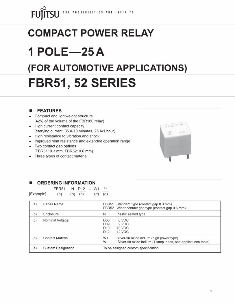
n FEATURESl Compactandlightweightstructure(42%ofthevolumeoftheFBR160relay)l Highcurrentcontactcapacity(carryingcurrent:35A/10minutes,25A/1hour)l Highresistancetovibrationandshockl Improvedheatresistanceandextendedoperationrangel Twocontactgapoptions(FBR51:0.3mm,FBR52:0.6mm)l Threetypesofcontactmaterial
n ORDERING INFORMATION
FBR51, 52 SERIES
COMPACT POWER RELAY
1 POLE—25 A (FOR AUTOMOTIVE APPLICATIONS)
1
2
FBR51, 52 SERIES
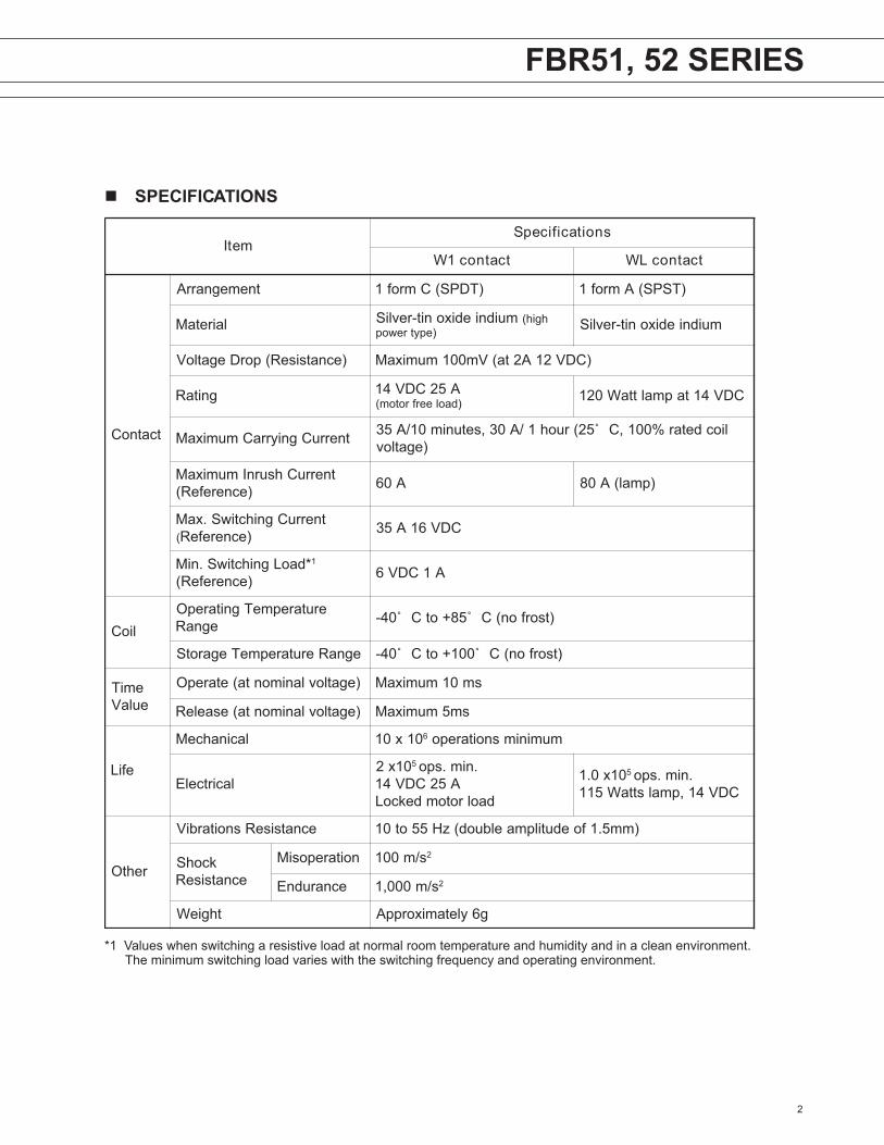
n SPECIFICATIONS
*1Valueswhenswitchingaresistiveloadatnormalroomtemperatureandhumidityandinacleanenvironment. Theminimumswitchingloadvarieswiththeswitchingfrequencyandoperatingenvironment.
metIsnoitacificepS
tcatnoc1W tcatnocLW
tcatnoC
tnemegnarrA )TDPS(Cmrof1 )TSPS(Amrof1
lairetaM muidniedixonit-revliS hgih()epytrewop muidniedixonit-revliS
)ecnatsiseR(porDegatloV )CDV21A2ta(Vm001mumixaM
gnitaR A52CDV41)daoleerfrotom( CDV41tapmalttaW021
tnerruCgniyrraCmumixaM liocdetar%001,C˚52(ruoh1/A03,setunim01/A53)egatlov
tnerruChsurnImumixaM)ecnerefeR( A06 )pmal(A08
tnerruCgnihctiwS.xaM( )ecnerefeR CDV61A53
*daoLgnihctiwS.niM 1
)ecnerefeR( A1CDV6
lioCerutarepmeTgnitarepO
egnaR )tsorfon(C˚58+otC˚04-
egnaRerutarepmeTegarotS )tsorfon(C˚001+otC˚04-
emiTeulaV
)egatlovlanimonta(etarepO sm01mumixaM
)egatlovlanimonta(esaeleR sm5mumixaM
efiL
lacinahceM 01x01 6 muminimsnoitarepo
lacirtcelE01x2 5 .nim.spo
A52CDV41daolrotomdekcoL
01x0.1 5 .nim.spoCDV41,pmalsttaW511
rehtO
ecnatsiseRsnoitarbiV )mm5.1foedutilpmaelbuod(zH55ot01
kcohSecnatsiseR
noitareposiM s/m001 2
ecnarudnE s/m000,1 2
thgieW g6yletamixorppA

3
FBR51, 52 SERIES
MODEL Nominal Coil Must operate Thermal voltage resistance W1 contact (±10%) (at 20°C) voltage resistance
FBR52ND06-W1 6VDC 45Ω3.6VDC(at20°C) 4.5VDC(at85°C)
FBR52ND09-W1 9VDC100Ω5.4VDC(at20°C) 6.8VDC(at85°C) 65°C/WFBR52ND10-W1 10VDC 135Ω6.3VDC(at20°C) 7.9VDC(at85°C)
FBR52ND12-W1 12VDC180Ω7.3VDC(at20°C) 9.2VDC(at85°C)
n COIL DATA CHART1. FBR51 Series
2. FBR52 Series
ledoM lanimoNegatlov
lioCecnatsiser)%01±()C˚02ta(
etarepotsuMegatlov
lamrehTecnatsiser
tcatnoc1W tcatnocLW
1W-60DN15RBF LW-60DN15RBF CDV6 06 )C˚02ta(CDV6.3)C˚58ta(CDV5.4
W/C˚371W-90DN15RBF LW-90DN15RBF CDV9 531 )C˚02ta(CDV4.5
)C˚58ta(CDV8.6
1W-01DN15RBF LW-01DN15RBF CDV01 081 )C˚02ta(CDV3.6)C˚58ta(CDV9.7
1W-21DN15RBF LW-21DN15RBF CDV21 042 )C˚02ta(CDV3.7)C˚58ta(CDV2.9

4
FBR51, 52 SERIES
n SUITABLE APPLICATIONS
Recommended Normal load current model (example) Application (12 VDC system) Description For 16 V or less For instantaneous motor load voltage 20 V or more load voltage
PowerWindows 20to25A forwardandreverseFBR51Nn-W1FBR52Nn-W1 (switchingatmotorlocking) motorcontrol
AutomaticDoorLock 18to25A forwardandreverseFBR51Nn-W1FBR52Nn-W1 (switchingatmotorlocking) motorcontrol
Tilt-LockWheel 20A forwardandreverseFBR51Nn-W1FBR52Nn-W1 (switchingatmotorlocking) motorcontrol
Sunroof 20to30A forwardandreverseFBR51Nn-W1FBR52Nn-W1 (switchingatmotorlocking) motorcontrol
AdjustableDoorMirror 3to5A forwardandreverse FBR51Nn-W1 (switchingatmotorlocking) motorcontrol 8to12A(INRUSH) forwardandreverse AutomaticAntenna break2Amaximum motorcontrol FBR51Nn-W1 (motor-free)
Auto-Cruise 2to3A powershutoffandsolenoid FBR51Nn-W1
Lamploads 120Watts forupto100Koperations FBR51Nn-WL
Others CarAudioSystem,etc. FBR51Nn-W1
•Fortheloadconditionwherehighervoltagewouldbeencounteredduringcontactbreak,FBR52serieswithwidercontactgapisrecommended.
n CHARACTERISTIC DATA1. MAXIMUM BREAK CAPACITY 2. LIFE
Voltage between contacts (VDC)10
10
15
12
20
25303540
50
Con
tact
sw
itchi
ng c
urre
nt (A
)
2015 25 3530 40 50
Locked motor load
Resistive load
FBR51
FBR52FBR51FBR52
Locked motor current (A)
14 VDC Motor locked load
10
5
10
20
30
Num
ber o
f ope
ratio
ns (x
104 )
2015 25 3530 40 50
High power type(-W1)

5
FBR51, 52 SERIES
0100101
20
40
60
80
100
(RL-1)20 sec
20 A
0 A
20 A
0 A
(RL-2)
0.3 sec
10 sec0.3 sec
100101
1000
100
10
(measured at 6 V-1 A)
0100101
20
40
60
80
100
100101
1000
m½
100
10
(measured at 6 V-1 A)
M
N.O.
N.C.
0 A4 A
20 A
16 A
M
RL-1
RL-2
N.O.
N.C.
N.O.
N.C.
3. LIFE TEST (EXAMPLE)
•Testitem14VDC-20Amotorlock200,000operationsminimum(FBR52n-W1type)
•Testcircuit
•Currentwaveform
•Shiftofpick-updrop-outvoltage
•Shiftofcontactresistance
PICK-UP
Initial
Perc
ento
frat
edc
oilv
olta
ge(%
)
Numberofoperations(x104)
BreakMake
ContactResistance(mΩ)
Initial
DROP-OUT
• Shift of pick-up and drop-out voltage
No. of operations (x104)
% o
f rat
ed c
oil v
olta
ge
0100101
20
40
60
80
100• Test item 14 V DC-25 A Motor lock 200,000 operations minimum (FBR51 -W1 type)
• Current wave form
• Test circuit
(RL-1)20 sec
25 A
0 A
25 A
0 A
(RL-2)
0.3 sec
10 sec0.3 sec
• Shift of contact resistance
100101
1000
100
10
BreakMake
(measured at 6 V-1 A)
M
RL-1
RL-2
N.O.
N.C.
N.O.
N.C.
PICK-UP
DROP-OUT
Con
tact
resi
stan
ce
No. of operations (x104)

6
FBR51, 52 SERIES
010010 201
20
40
60
80
100
10010 201
1000
100
10
0A10A
80A
N.O.
4. COIL TEMPERATURE RISE 5. OPERATING COIL VOLATGE RANGE (EXAMPLE)
Coil t
empe
ratu
re ri
se
(°C)
Applied time (minutes)
00 10 20 30
20
40
60
80
100
120
0.8 W
at 20°C
0.6 W
(2) carrying current : 10 A applied coil power
0.8 W0.6 W
(1)carrying current : 0 A applied coil power
0.8 W0.6 W
(3) carrying current : 20 A applied coil power
–30 0 50 100
5
10
15
Appl
ied
volta
ge to
the
coil
Operating temperature (°C)
NOTE : Intermittent coil operation is required in this region at 20 A or more
(V)
CONTINUOUSLYAPPLICABLE COILVOLTAGE RANGE
carrying current carrying current.
Appl
ied
volta
ge to
the
coil
Operating temperature (°C)
NOTE : Intermittent coil operation is required in this region at 20 A or more
–30 0 50 100
5
10
15(V)
CONTINUOUSLYAPPLICABLE COILVOLTAGE RANGE
carrying current.
[FBR51ND09-n] [FBR51ND12-n]
•Testitem14VDC-80A(120W)lampload100,000operationsminimum(FBR51n-WLtype)
•Testcircuit
•Currentwaveform
•Shiftofpick-updrop-outvoltage
•Shiftofcontactresistance
Initial
Perc
ento
frat
edc
oilv
olta
ge(%
)
Numberofoperations(x104)
ContactResistance(mΩ)
Initial
PICK-UP
DROP-OUT
Numberofoperations(x104)

7
FBR51, 52 SERIES
6. VIBRATION RESISTANCE CHARACTERISTICS
7. SHOCK RESISTANCE CHARACTERISTICS
FBR51
Y
Z
X
Frequency : 10~2000 HzAcceleration : 100 m/s2 maxDirection of vibration : see under diagramDetection level : chatter > 100 µs
Acc
eler
atio
n
(m/s2)
10
50
100
10 50 100 500 1000 2000
5 1 0.5 0.1 0.01
Dual amplitude (mm)
Frequency (Hz)
Automotive electronics standard
44 m/s2
Range where chattering occursN.O. contactcoil not energizedon X-direction
0
200
400
600
800
1,000
X1 X2 Y1 Y2 Z1 Z2
Shoc
k le
vel
(m/s2)
Shock direction : N.C. contact (coil de-energized)
Shock application time : 11 ms, half-sine waveTest material : coil, energized and de-energizedShock direction : set under diagramDetection level : chatter > 100 µs
FBR51
Z2
Z1
Y1Y2
X2
X1
: N.C. Contact (coil energized)
n REFERENCE DATA
FBR52n = 100
OperateRelease
Distribution of operate and release voltage
Nominal voltage multiplying factor (%)
80
60
40
20
0 10 20 30 40 50 60 70 800
Dis
tribu
tion
(%)
FBR52n = 100
OperateRelease
Distribution of operate and release time
Time (ms)
100
80
60
20
40
0 1 2 3 4 5 6 7 80
Dis
tribu
tion
(%)
Contact resistance (m ohm)
Distribution of contact resistance
FBR52n = 100
100
80
60
20
40
0 10 20 30 40 50 60 70 800
Dis
tribu
tion
(%)

8
FBR51, 52 SERIES
n DIMENSIONS
45pcs/tube
20.3
Max
.
601Max.
Dimensions
19.0Max.
51ND12-W1
F&T 9427
PCboardmountingholelayout(BOTTOMVIEW)
Schematics(BOTTOMVIEW)
Tubecarrier
Unit:mm
12.1
+0.2
15.5+0.2
R0.4
R0.4
13.7
+0.3
0.3
2.5 10.2
1t=0.4
1 (1.6)
(1.05)
3.5
10
5
1.2t=0.3
1
2
5 4
3
1
2
5 4
3
N.C.
N.O.(-)
COM(+)
FBR50-WL
FBR50-W1
N.C.
N.O.
COM
4-O1.3
O1.4
10.22.5
10
5
RefertothetestcircuitatCHARACTERISTICDATAforconnection,andpolarity.
JapanFujitsuComponentLimitedGotanda-ChuoBuilding3-5,Higashigotanda2-chome,Shinagawa-kuTokyo141,JapanTel:(81-3)5449-7010Fax:(81-3)5449-2626Email:[email protected]:www.fcl.fujitsu.com
North and South AmericaFujitsuComponentsAmerica,Inc.250E.CaribbeanDriveSunnyvale,CA94089U.S.A.Tel:(1-408)745-4900Fax:(1-408)745-4970Email:[email protected]:http://www.fujitsu.com/us/services/edevices/components/
EuropeFujitsuComponentsEuropeB.V.Diamantlaan252132WVHoofddorpNetherlandsTel:(31-23)5560910Fax:(31-23)5560950Email:[email protected]:http://www.fujitsu.com/emea/services/components/
Asia PacificFujitsuComponentsAsiaLtd.102EPasirPanjangRoad#04-01CitilinkWarehouseComplexSingapore118529Tel:(65)6375-8560Fax:(65)6273-3021Email:[email protected]:http://www.fujitsu.com/sg/services/micro/components/
Fujitsu Components International Headquarter Offices
©2006FujitsuComponentsAmerica,Inc.Allrightsreserved.Alltrademarksorregisteredtrademarksarethepropertyofftheirrespectiveowners.FujitsuComponentsAmericadoesnotwarrantthatthecontentofdatasheetiserrorfree.InacontinuingefforttoimproveourproductsFujitsuComponentsAmerica,Inc.reservestherighttochangespecifications/datasheetswithoutpriornotice.Rev.03/17/2006.