for approval - kentecdisplayked).pdf · fs- k50dwn2-v1-ff -01 for approval we are pleased in...
TRANSCRIPT

YOUR MODULE NO.: OUR MODULE NO.: K50DWN2-V1-FF
YOUR SPEC NO.: OUR FULL SPEC NO.: FS- K50DWN2-V1-FF -01
FOR APPROVAL
WE ARE PLEASED IN SENDDING YOU HEREWITH OUR SPECIFICATION AND DRAWING FOR YOUR APPROVAL. PLEASE RETURN TO US ONE COPY OF “FOR APPOVAL” WITH YOUR APPROVED SIGNATURES.
APPROVED BY
APPROVED BY CUSTOMER

FS-K50DWN2-V1-FF
28/Mar/2011
PAGE 1 OF 13
Product Standard LCD Module 800 x RGB x 480 Dots 5” 16.7M colors TFT display Wide temperature With white LED backlight With touch screen
K50DWN2-V1-FF
Kentec Electronics (Displays) Limited URL: http://www.kentecdisplay.com E-mail: [email protected]; [email protected]
FS-K50DWN2-V1-FF
28/Mar/2011
PAGE 2 OF 13
CONTENTS Page No. 1. DOCUMENT REVISION HISTORY 3 2. GENERAL DESCRIPTION 4 3. MECHANICAL SPECIFICATIONS 5-6 4. INTERFACE SIGNALS 7 5. ABSOLUTE MAXIMUM RATINGS 8 6. ELECTRICAL SPECIFICATIONS 8 7. OPTICAL CHARACTERISTICS 9 8. TIMING CHARACTERISTICS 10 9. RELIABILITY TEST ITEM 11 10. SUGGESTIONS FOR USING LCD MODULES 12

FS-K50DWN2-V1-FF
28/Mar/2011
PAGE 3 OF 13
1. Document revision history : DOCUMENT
REVISION DATE DESCRIPTION PREPARED BY
APPROVED BY
01 2011.03.28 Preliminary verions. MF Zou

FS-K50DWN2-V1-FF
28/Mar/2011
PAGE 4 OF 13
2. General Description
• 5.0”(diagonal), 800 x RGB x 480 dots, 16.7M colors, Normal white TN, TFT LCD module. • Viewing Direction: 6 o’clock. • Controller: SSD1963 graphic controller/driver. • 8080 system 8-bit or 16-bits • With internal voltage booster. • Logic voltage: 3.3V (typ.). • With 4-wire resistive touch screen
3. Mechanical Specifications The mechanical detail is shown in Fig. 1 and summarized in Table 1 below.
Table 1 Parameter Specifications Unit
Outline dimensions 118.5(W) x 77.55(H) x 7.9(D) (Exclude FPC, cables of backlight) mm
TP aiew area -- mm TP view area -- mm
LCD active area 108.0(W) x 64.8(H) mm Display format 800 x RGB x 480 dots
Color configuration RGB Side-stripes -
Color TFT 800xRGBx480
Dot size 0. 135 (W) x 0.135(RGB) mm Weight TBD grams

FS-K50DWN2-V1-FF
28/Mar/2011
PAGE 5 OF 13
800(
RG
B)*
480
(T
FT
5"
WV
GA
)
VIE
WIN
G D
IRE
CT
ION
TR
AN
SM
ISS
IVE
Max
(Com
pone
nts)
Figure 1: Outline Drawing 1

FS-K50DWN2-V1-FF
28/Mar/2011
PAGE 6 OF 13
Com
pone
nts
(H=2
.5M
ax)
Com
pone
nts
(H=4
.5M
ax)
DB
15D
B14
DB
13D
B12
DB
11D
B10
DB
9D
B8
GN
D
DB
7D
B6
DB
5
DB
4D
B3
DB
2D
B1
DB
0G
ND
NC
NC
CS
NC
NC
NC
NC
NC
NC
VD
DV
DD
NC
NC
NC
Figure 2: Outline Drawing 2

FS-K50DWN2-V1-FF
28/Mar/2011
PAGE 7 OF 13
4. Interface signals Table 2: Pin assignment
Pin No. Symbol Description 1-2 LED_K 3-4 LED_A
Power supply for LED backlight
5 GND Power supply (system ground) 6 XR 7 YD 8 XL 9 YU
Terminal of touch panel.
10 GND Power supply (system ground) 11-13 NC No connection
14 RESET System reset pin 15 CS Chip select input
16-19 NC No connection 20 GND Un-used data pin, connect to GND
21-25 DB[0-4] Bi-directional data bus(DB0-DB4) 26-27 NC No connection 28-30 DB[5-7] Bi-directional data bus(DB5-DB7)
31 GND Un-used data pin, connect to GND 32-33 DB[8-9] Bi-directional data bus(DB8-DB9) 34-35 NC No connection 36-41 DB[10-15] Bi-directional data bus(DB10-DB15) 42-46 NC No connection 47-48 VDD Supply voltage for logic
49 DC Parallel Interface 50 RD I80 system: Serves as a read signal and reads data at the low level. 51 WR I80 system: Serves as a write signal and writes data at the rising edge.
52-58 NC No connection 59-60 GND Power supply (system ground)
Note: LCD interface circuit example ( ).

FS-K50DWN2-V1-FF
28/Mar/2011
PAGE 8 OF 13
5. Absolute Maximum Ratings 5.1 Electrical Maximum Ratings – for IC Only
Table 3: Electrical Maximum Ratings – for IC Parameter Symbol Min. Max. Unit Note
Supply voltage VCC -0.3 5.0 V 1 LED forward current If -- 30 mA
LED reverse Vr -- 5.0 V Note: 1.VCC, GND must be maintained.
2.The modules may be destroyed if they are used beyond the absolute maximum ratings. 5.2 Environmental Condition
Table 4
Operating temperature
(Topr)
Storage temperature
(Tstg) (Note 1)
Item
Min. Max. Min. Max.
Remark
Ambient temperature -20°C +70°C -30°C +80°C Dry
Humidity (Note 1) 80% max. RH for Ta ≤ 40°C < 50% RH for 40°C < Ta ≤ Maximum operating temperature
No condensation
Note 1: Product cannot sustain at extreme storage conditions for long time. 6. Electrical Specifications
Typical Electrical Characteristics At Ta = 25 °C, VCC=IOVCC= 3.3V, GND=0V.
Table 5 Parameter Symbol Conditions Min. Typ. Max. Unit
Supply voltage (logic) VDD-GND 3 3.3 3.6 V VIH 0.8VDD - VDD V Input signal voltage VIL 0 - 0.2VDD V
Supply current (Logic & LCD) IDD VDD=3.3V - 15 19 mA
Supply current (1) (LED) ILED - 36 40 mA
Note (1): LED backlight required current constant power supply. LED circuit was in 2 chain parallel and with 6 LEDs serial per chain.
FS-K50DWN2-V1-FF
28/Mar/2011
PAGE 9 OF 13
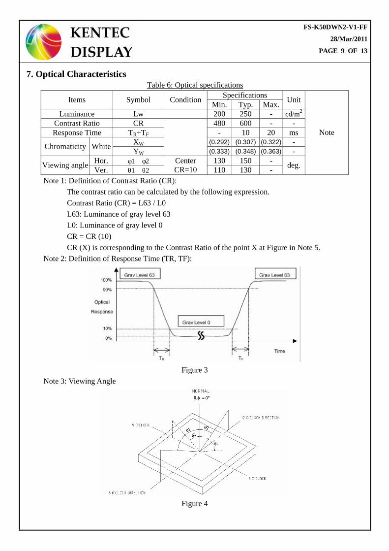
7. Optical Characteristics Table 6: Optical specifications
Specifications Items Symbol Condition Min. Typ. Max.
Unit
Luminance Lw 200 250 - cd/m2 Contrast Ratio CR 480 600 - - Response Time TR+TF - 10 20 ms
XW (0.292) (0.307) (0.322) - Chromaticity White YW
(0.333) (0.348) (0.363) - Hor. φ1 + φ2 130 150 - Viewing angle Ver. θ1 + θ2
Center CR=10 110 130 -
deg.
Note
Note 1: Definition of Contrast Ratio (CR): The contrast ratio can be calculated by the following expression. Contrast Ratio (CR) = L63 / L0 L63: Luminance of gray level 63 L0: Luminance of gray level 0 CR = CR (10) CR (X) is corresponding to the Contrast Ratio of the point X at Figure in Note 5. Note 2: Definition of Response Time (TR, TF):
Figure 3
Note 3: Viewing Angle
Figure 4

FS-K50DWN2-V1-FF
28/Mar/2011
PAGE 10 OF 13
The above “Viewing Angle” is the measuring position with Largest Contrast Ratio; not for good
image quality. View Direction for good image quality is 6 O’clock. Module maker can increase
the “Viewing Angle” by applying Wide View Film.
Note 4: Measurement Set-Up:
The LCD module should be stabilized at a given temperature for 20 minutes to avoid abrupt temperature change during measuring. In order to stabilize the luminance, the measurement should be executed after lighting Backlight for 20 minutes in a windless room.
Figure 5 8. AC Characteristics and Signal timing Please refer SSD1963 datasheet.
8.1 Driver code example for TI IDM-SBC ( ). 8.2 Driver code example for TI DK-LM3S9B96 ( ).

FS-K50DWN2-V1-FF
28/Mar/2011
PAGE 11 OF 13
9. Reliability Test Item Test Item Test Condition Remark
1 High temperature storage 70℃; 240H
2 Low temperature storage -20 ;℃ 240H
3 High temperature High humidity 50 ,℃ 80%RH; 240H Operation
4 High temperature operation 60 ;℃ 240H
5 Low temperature operation -10 ;℃ 240H
6 Temperature Shock -20 ?℃ 60℃; 100cycle, 1Hrs/cycle Non-operation
7 Electrostatic Discharge Contact ±4kV, Class B
Air ±8kV, Class B
8 Image sticking 25℃, 4H
9 Vibration
Frequency range : 10~55Hz Stoke : 1.5mm
Sweep : 10~55~10Hz 2 Hours for each direction of
X,Y,Z (total 6 Hours)
Non-operation JIS C7021, A-10
Condiction A : 15 minutes
10 Mechanical shock 100G, 6ms, ±X, ±Y, ±Z, 3 times for each direction
Non-operation JIS C7021, A-10
Condiction C
11 Vibration (with carton)
Random vibration : 0.015G2/Hz from 2~200Hz
-6dB/Octave from 200~500Hz
ICE 68-34
12 Drop (with carton)
Height : 60cm 1 corner, 3 edges, 6 surfaces
13 Pressure 5 kg, 5 sec
10. Suggestions for using LCD modules
10.1 Handling of LCM
10.1.1. The LCD screen is made of glass. Don't give excessive external shock, or drop from a high place.
10.1.2. If the LCD screen is damaged and the liquid crystal leaks out, do not lick and swallow. When the
liquid is attach to your hand, skin, cloth etc, wash it off by using soap and water thoroughly and
immediately.

FS-K50DWN2-V1-FF
28/Mar/2011
PAGE 12 OF 13
10.1.3. Don't apply excessive force on the surface of the LCM.
10.1.4. If the surface is contaminated ,clean it with soft cloth. If the LCM is severely contaminated , use
Isopropyl alcohol/Ethyl alcohol to clean. Other solvents may damage the polarizer . The following
solvents is especially prohibited: water , ketone Aromatic solvents etc.
10.1.5. Exercise care to minimize corrosion of the electrode. Corrosion of the electrodes is accelerated by
water droplets, moisture condensation or a current flow in a high-humidity environment.
10.1.6. Install the LCD Module by using the mounting holes. When mounting the LCD module make sure
it is free of twisting, warping and distortion. In particular, do not forcibly pull or bend the I/O cable or the
backlight cable.
10.1.7. Don’t disassemble the LCM.
10.1.8. To prevent destruction of the elements by static electricity, be careful to maintain an optimum
work environment.
- Be sure to ground the body when handling the LCD modules.
- Tools required for assembling, such as soldering irons, must be properly grounded.
- To reduce the amount of static electricity generated, do not conduct assembling and other work
under dry conditions.
- The LCD module is coated with a film to protect the display surface. Exercise care when peeling
off this protective film since static electricity may be generated.
10.1.9. Do not alter, modify or change the the shape of the tab on the metal frame.
10.1.10. Do not make extra holes on the printed circuit board, modify its shape or change the positions of
components to be attached.
10.1.11. Do not damage or modify the pattern writing on the printed circuit board.
10.1.12. Absolutely do not modify the zebra rubber strip (conductive rubber) or heat seal connector
10.1.13. Except for soldering the interface, do not make any alterations or modifications with a soldering
iron.
10.1.14. Do not drop, bend or twist LCM.
FS-K50DWN2-V1-FF
28/Mar/2011
PAGE 13 OF 13
10.2 Cautions for installing and assemably if the module with Touch Panel
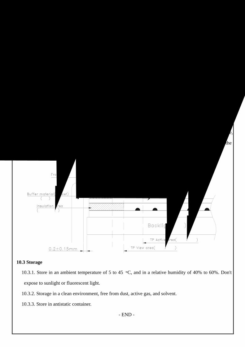
10.2.1. Use a buffer material (Gasket) between the touch panel and Front-case to protect damage and
wrong operating. The dimension of the buffer material’s edge between the TP V.A. edge is Min. 0.3mm.
10.2.2. We recommend to design a case that it can’t over the boundary of the active area Max. 0.5mm in
order to prevent an operation at outside of the active area which can’t guarantee the specified durability,
because operation at the outside of the active area cause serious damage of a transparent.
10.2.3. When design case for installing Module, you would consider give a distance about 0.2±0.15mm
between the module edge to case inside.
10.2.4. The corners of the product are not chamfered. When positioning and fixing the product on the case,
we sugguest that you would provide a R part on the conner of the case so as not to apply load on the
corner of the transparent module.
驱动区域边缘
可视区域边缘
背光
绝缘油墨区域
缓冲材料 垫圈
机壳
触摸屏
10.3 Storage
10.3.1. Store in an ambient temperature of 5 to 45 °C, and in a relative humidity of 40% to 60%. Don't
expose to sunlight or fluorescent light.
10.3.2. Storage in a clean environment, free from dust, active gas, and solvent.
10.3.3. Store in antistatic container.
- END -