for amie coaching :- jyothis academy kottayam. phone ... a suitable welded connection for lap joint...
TRANSCRIPT
1
2

3
Slenderness Ratio Permissible Stress
(kg/cm2)
140 531
150 474
160 423
170 377
180 336
190 300
200 270
6. (a ) Design a suitable welded connection for a lap joint
between an angle 70 mm x 70 mm x 8 mm, carrying
an axial load of 10 tonnes and a gusset plate 10 mm
thick. Take the permissible shear stress in the weld
as 1025 kg/cm2• 10
(b) A beam of 8·0m effective span carries a uniformly
distributed load of 2000 kg/m including its own
weight. Design the beam. The compression flange of
the beam is held against lateral displacement.
Take permissible bending stress= 1650 kg/cm2,
permissible shear stress= 945 kg/cm2, and
permissible deflection= span/325. 10
7. Design a two-way RCC slab over a room of size
5·50 m x 6·70 m, simply-supported at the edges with its
comers held down. The roof of the room is apprbachable.
Use M 15 grade concrete and Fe415 steel. Draw a plan
of the slab showing details of the reinforcement and also
the sectional details. Use working stress method of design. 20
8. Design a RC column square in section, subjected to an
axial load of 100 tonnes at working stress. Effective height
of the column is 3·5 m. Percentage of reinforcement in this
column should be 2%. UseM25 grade concreteandFe415
grade steel. Also, design the isolated column footing. Take
permissible bearing capacity of soil as 10 tonnes/m2.
Sketch the reinforcement details of column and its
foundation.
Groupe
20
9. Choose the correct answer for the following: 1 x20
( i) A beam simply supported at the ends has a span I.
It is subjected to equal and opposite end couple M' .
If EI is flexural regidity of the beam, its central
deflection is given by
(d) M' 12 !16EI.
( ii) As per IS 800, the maximum deflection in a beam
should not exceed
(a) L /180
(b) L /250

4

5

6

7
W'OB: 7 AN :CV407 ( 1433)
ANALYSIS AND DESIGN OF STRUCTURES
Time : Three hours
Maximum Marks : 100
Answer FIVE questions, taking ANY TWO from Group A, · ANY TWO from Group B and AIL from Group C.
All parts of a question (a, b, etc. ) should
be answered at one place.
Answer should be brief and to-the-point and be supplemented
with neat sketches. Unnecessary long answers may
result in Joss of marks.
Any missing or wrong data may be assumed suitably giving proper justification.
Figures on the right-hand side margin indicate full marks.
Design data book is not permitted to use.
Use ofiS 800, IS 456 and steel tables are permitted.
Group A
1. Find the forces in the truss members shown in Fig. I. 20
c T 1·5 m
+ Fig. 1

8

9

10

11

12

13
S'l0:7AN:CV 407 (1433)
ANALYSIS AND DESIGN OF STRUCTURES
Time : Three hours
Maximum Marks : 100
Answer FIVE questions, taking ANY TWO from Group A, ANY TWO from Group 8 and ALLfrom Group C.
All parts of a question ( a,b,etc.) should be answered at one place.
Answer should be brief and to-the-point and be supplemented with neat sketches. Unnecessary long answers may
result in loss of marks.
Any missing or wrong data may be assumed suitably giving · proper justification.
Figures on the right-hand side margin indicate full marks.
Design data handbook is not permitted to use. Use of IS 800, IS 456 and steel tables are permitted.
Group A
l. Analyse the moment distribution method and draw shear force and bending moment diagram : 20
l6ml.
Fig.l;

14
2. Find out 80 , and 8Ch for the frame shown in Fig. 2 :
I 40 kN
D
Fig. 2
3. A Warren girder of 60 m span is built up of equilateral triangles and has 10 panels of 6 m each. Draw an influence line for foJ:.ce for the left-hand diagonal in the fourth panel from the left-hand support. State the exact position of a single rolling load in the panel so that the force in the diagonal is zero.
4. A three-hinged circular arch has a span of 50 m and a rise of 1 0 m. A load of 200 kN crosses the arch from left to right. Determine the (i) maximum horizontal thrust, and (ii) maximum bending moment, positive and negative, at a
20
20
section 15 m from the left-hand hinge. 20
Group B
5. Design a welded plate girder consisting of only plates for the following: Effective span 12m. UDL 25 kN/m, three concentrated loads moving on the span, eact'l 120 kN and spaced at 3 m apart. Draw neat sketches. 20
S"I0:7AN:CV 407 ( 1433) ( 2 ) (Continued)
6. Crane loads on a gantry girder and other data are:
Crane capacity Wk = 100 kN, crane girder weight,
We= 80 kN, wheel spacing, a= 3·5 m, weight of crab,
Wr = I 0 kN, column spacing= gantry span = 600 mm;
minimum edge distance· of crane, g = 1000 mm. Design a
channel section which can be placed at the level of the top
flange and give a lateral support to the girder. 20
·7. A doubly reinforced rectangular beam is 300 mm wide
and 450 mm deep and is subjected to a bending moment of
90 kN-m. If the limiting stresses in concrete and steel are
5N/mm2 and 140 N/mm2, determine area of steel rebars.
Assume m = 18.
8. Design a combined footing for two RC columns, A and B,
separated by a distance of 4 m c/c : Column A is 500 mm2
and carries a load of 1200 kN, whereas column B is
600 mm2 and carries a load of 1600 kN. The safe bearing
capacity of' soil is 200 kN/m2• Use M 20 grade c.oncrete
20
and Fe 415 grade of steel. 20
Group C
9. Answer the following in brief:
(i) Method of section for plane truss
(ii) Virtual work method for deflection of truss
(iii) Moment area method
(iv) Conjugate beam method
(v) Kani's method
S' I 0:7 AN :CV 407 ( 1433) ( 3 )
2 X 10
( Turn Over)

15

16
S'll:7AN:CV407 (1433)
ANALYSIS AND DESIGN OF STRUCTURES
Time : Three hours
Maximum Marks : 100
Answer FIVE questions, taking ANY TWO from Group A, ANY TWO from Group B and ALL from Group C.
All parts of a question (a, b, etc.) should · be answered at ·one place.
Answer should be brief and to-the:.point and be supplemented with neat sketches. Unnecessary ll}ng answers may
result in loss of markS.
Any missing or wrong data may be assumed suitably giving proper justification.
Figures on the right-hand side margin indicate full marks.
Group A
1. Find the vertical and horizontal deflection of the end A of the member ABCD shown in Fig. l. Take E = 210 kN/mm2• 20
4m C.---------c:;:;D
2m E e
IOkN> ~ B X ~
2m~
A
/ 2 = 8 x l 07 mm4
Fig. 1

17
2. A three-hinged segmental arch ACB has a span of 30m and a rise of 5 m. It supports a concentrated load of
· 150 kN at a section 7·5 m from the left support. Find
the reactions at the support and maximum positive and
negative bending moments. 20
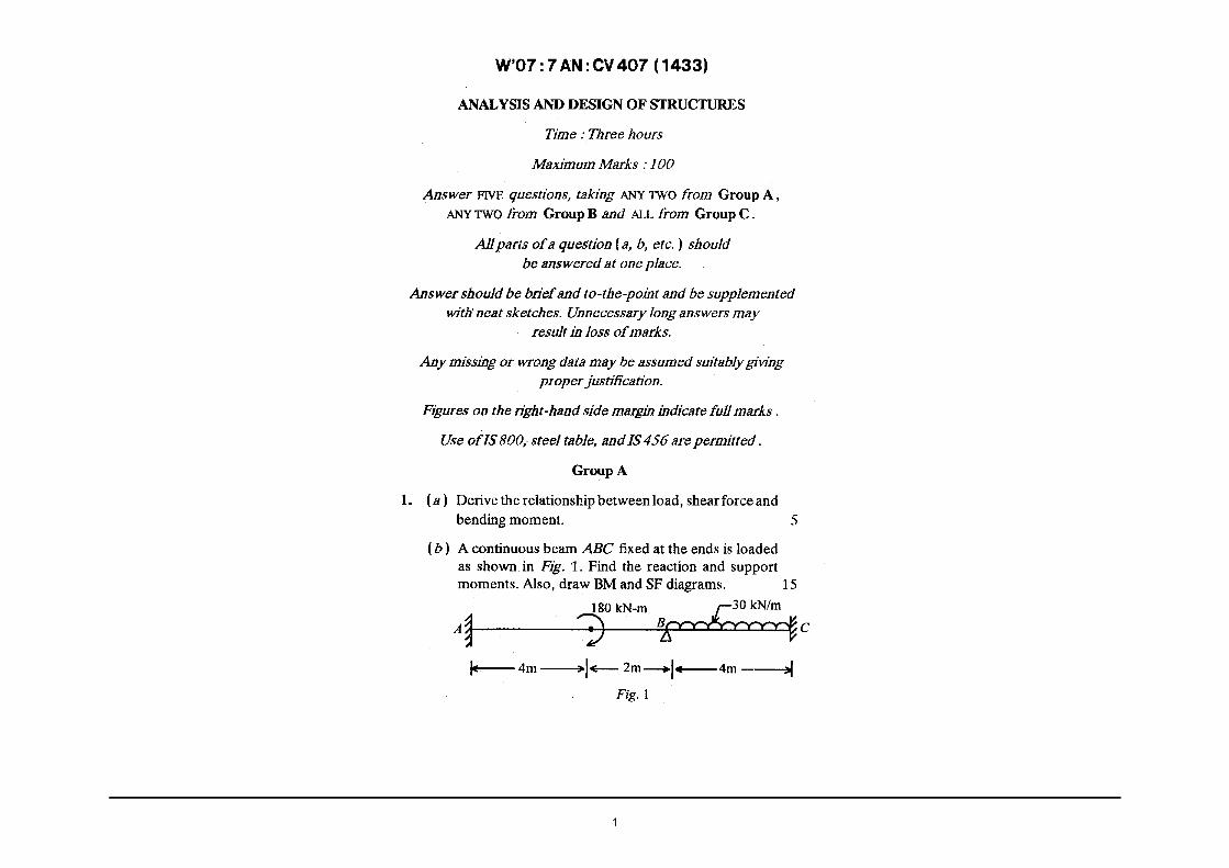
3. A continuous beam ABC fixed at the ends is loaded
as shown in Fig. 2. Find the reactions and support
moments. Also, draw shear force and bending· moment
4.
· diagrams. Use the moment distribution method. 20
A t~--4-m_ 6 m18_3_kN_/_m_2 _m___,l,._B_"_'t_2,:W-•jc
Fig.2
A cantilever truss of Warren-type is loaded as shown in
Fig. 3. Determine stresses in the members of the truss. 20
2kN
2kN
Fig.3
2kN
1 kN
S'll :7AN :CV407 (1433) ( 2 ) ( Continued)
Group B
5. Design a built up battened column to carry an axial load of 2450 kN. Length of column is 4·85 m. It is effectively held in position at the ends but restrained against rotation at one end only. Take~,= 250 N/mm2• Also, design the battens. 20
6. (a) A tension member of a roof truss consists of single angle ISA ,150 mm x I15 mm x 8 mm. It carries a tension of 180 kt.J'. Find the length of 6 mm weld at extremities of the longer leg for its connection
7.
to gusset. I 0
(b) Design a single angle discontinuous strut to carry a load of 90 kN. The length of strut is 3m. The strut is connected by one rivet at each end. I 0
Design a doubly reinforced beam to carry a superimposed load of 60 kN/m run. The overall depth and width of the beam are restricted to 840 mm and 300 mm, respectively. The beam has a clear span of 5 m and a bearing of 50 em on each end. Use M20 concrete and Fe 4I5 steel. 20
8. A square column of size 350 mm x 350 mm carries a load of I 000 kN. Design a square footing to support the column. The S.B.C. of the soil is 100 kN/m2• Use M20 grade concrete and HYSD steel of grade Fe 415. 20
Group C
9. Answer the following:
(i) State three moment equation.
(ii) State relation between shear force and bending moment.
IO X 2
S'll :7AN :CV407 {1433) ( 3 ) (Turn Over)

18

19
W'12:7AN:CV 407 (1433)
ANALYSIS AND DESIGN OF STRUCTURES
Time : Three hours
Maximum Marks : 100
Answer FIVE questions, t~king ANY TWO from Group A, ANY TWO from Group B and ALL from Group C.
All parts of a question (a, b, etc. ) should be answered at one place.
Answer should be brief and to-the-point and be supplemented with neat sketches. Unnecessary long answers may
result in loss of marks.
Any missing or wrong data may be assumed suitably giving proper justification.
Figures on the right-hand side margin indicate full marks.
Group A
1. Analyse the continuous beam shown in Fig.1 by moment distribution method. Sketch bending moment and shear force diagrams. 20
10 kN/m
1m
40 kN
2·5m! 2·5m
i Q) ~5m----:)j(~4m ~~ Sm ~
Fig. 1
2. Analyse the structure shown m Fig. 2 by the stiffness method: 20
20

21

22
l.
S'12:7AN :CV 407 (1433)
ANALYSIS AND DESIGN OF STRUCTURES
Time : Three hours
Maximum Marks : 100
Answer FIVE questions, taking ANY TWO from Group A, ANY TWO from Group B and ALL from Group C.
All parts of a question (a, b, etc.) should be answered at one place.
Answer should be brief and to-the-point and be supplemented with neat sketches. Unnecessary long answers may
result in loss of marks.
Any missing or wrong data may be assumed suitably giving proper justification.
Figures on the right-hand side margin indicate full marks.
Group A
Using moment distribution method, analyse the portal frame shown in Fig. 1 : 101 1 I
3m 2I
I 1 Sm
l I I
k I
4m >j Fig. 1
20
(Turn Over)

23
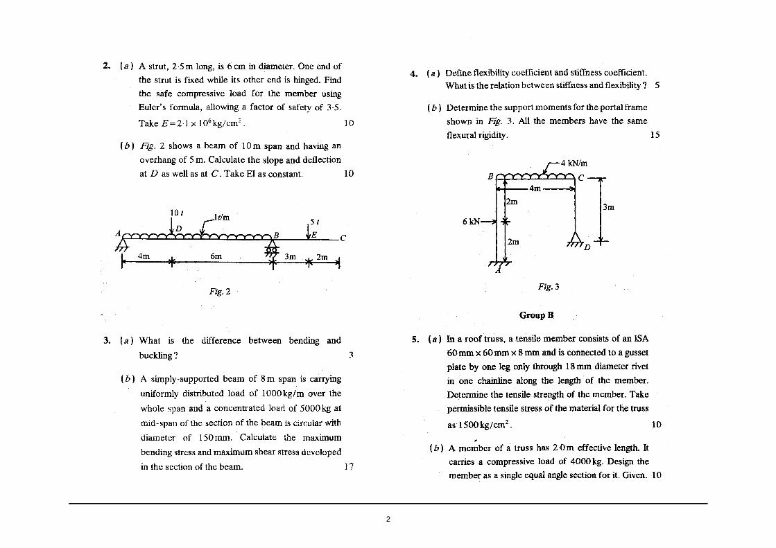
2. (a) For a two hinged parabolic arch (Fig. 2), moment of inertia of the section varies as secant of the slope. Determine (i) reactions at the supports; (ii) normal thrust and radial shear at section D; and (iii) bending moment at C. I 0
2kN/m c IIIIIJIIIflllfllllll
I 1 4m I
I I ------.------4m I
I
I'-- 8 m --..;~+"'"--I
8m ---ll~
Fig.2
(b) Derive the general expression of the horizontal thrust in a parabolic two-hinged arch due to a rise of temperature 9°C. Coefficient of linear expansion a per °C. Moment of inertia varies as the secant of slope of the rib axis. 10
3. Draw the influence iines for forces in the members U2U3,
U2 L3 and L~3 of a truss (Fig. 3). If a line load of 8 kN/m traverses from L1 to Ls, find the value of maximum forces in these members. 20
u3
4·5mT1m ~------~--------~~------~------~L,Jl L2 L4
6m 6m 6m 6m
Fig.3
S'l2:7AN :CV407 (1433) ( 2 ) ( Continued)
4. (a) A beam AB of length I is fixed at both the ends. It carries a distributed load varying linearly from zero at left end to w at the right end. Calculate the fixed end moments.
(b) A beam AB of span 6 m is fixed at A and simply supported at B. It carries two concentrated loads 150 kN and 90 kN at C and D distant 1·5 m and 4·5 m from the fixed end A. Draw the bending moment diagram.
Group B
5. (a) Design a seated connection for a beam ISLB 2 7 5 @ 324 N/m supported on the web of a coh.itnn ISHB 250@ 500 N/m. End reaction of the beam is 100 kN.
(b) An 1-section purlin has to be provided for a roof with
an effective span of 12m. The principal rafters are placed 3 ·6 m c/c. Spacing of purlins is 1·8 m. Pitch of the roof is 30°, weight of roofmg material is 200 N/m2
,
and normal wind pressure is 1·2 kN/m2• Design a suitable section of pur lin.
6. Des1gn a suitable lacing for a composite column consisting two ISLC 350 with the back-to-backspacing of220 mm. The flanges of channels are 100 mm. The rivets are to be attached at 60 mm from the web. Slenderness ratio of the column is A.= 40. Size of rivets has to be 20 mm.
7. The cross-section of a singly reinforced simply-supported beam is 500 mm x 800 mm. Reinforcement consists of 5 bars of20 mm diameter. Determine the maximum stress in concrete when steel is stressed to 200 N/mm2• M20 concrete and Fe415 steel are used. Also, determine the
10
10
10
10
20
load it can carry for an effective span of 6 m. 20
S'l2:7AN :CV407 (1433) ( 3 ) (Turn Over)

24
8.
9.
(a) A reinforced concrete slab 20 m x 4 m in plan has to carry 6 kN/m2
, inclusive of its own weight. Determine (l) effective depth of slab, and ( ii) reinforcement. M20 concrete and Fe 415 steel are to be used. 10
(b) Design a short circular column to carry an axial load of 1500 kN using M20 concrete and Fe 415 steel. 10
Group C
Answer the following in brief: 10 X 2
(i) What is the relative stiffness of members as required for moment distribution method.
(il) Distinguish between lacing and batten for compo-site columns.
(iil) Write salient features ofKani's method.
(iv) Compare the Euler's concept and Rankine concept for analysis of a column.
(v) Give the degree of internal indeterminacy and exter-nal indeterminacy of a plane truss.
~ (vi) Write the Castigliano's first strain energy theorem.
(vii) Differentiate between a riveted connection and a welded connection of steel plates.
(viii) Explain the concept of splicing a plate girder.
(ix) Explain the term 'bond length of reinforcement bar.'
(x) What are the functions of proving 2-legged stirrups in beam?
S'12:7AN :CV407 (1433) ( 4 ) AG-800

25
W'13: 7AN:CV 407 (1433)
ANALYSIS AND DESIGN OF STRUCTURES
Time : Three hours
Maximum Marks : 100
Answer FIVE questions, taking ANY TWO from Group A, ANY TWO from Group B and ALL from Group C.
All parts of a question (a,b,etc.) should be answered at one place.
Answer should be brief and to-the-point and be supplemented with neat sketches. Unnecessary long answers may
result in loss of marks.
Any missing or wrong data may be assumed suitably giving proper justification.
Figures on th'e right-hand side margin indicate full marks.
Group A
L (a) Determine the degree of external static indeterminacy
of the beams as shown in Figs. 1 and 2 for the general
case loading ? 5
~A B c D
~ ~ ~ Fig. l
p ~ t R s T • ~ ~
Fig.2
26
(b) Draw the bending moment and ~hear force diagrams
for the beam loaded as 5hown in Fig. 3. Also, determine the maximum bending moment and the point
at which it occurs ?
lOkN 5kN
2m ~ 2m --. .. t-"- 2·5m~
Fig.3
2. A beam PQRS of the uniform cross-section is loaded
as shown in Fig. 4. Determine (i) slope at pointR, (ii) slope
at point P, and (iii) deflection at point S. Use
conjugate beam method. Given: E"" 200 x 106 kN/m2;
15
kN
I= 120 X to-6 m4• 20
p s Q l:kN
/J ~ .f--2m ,r 2m " IJ 2m-,f
Fig.4
3. (a) Briefly explain the statement of Castigliano's theorem?
Also, explain its uses. 5
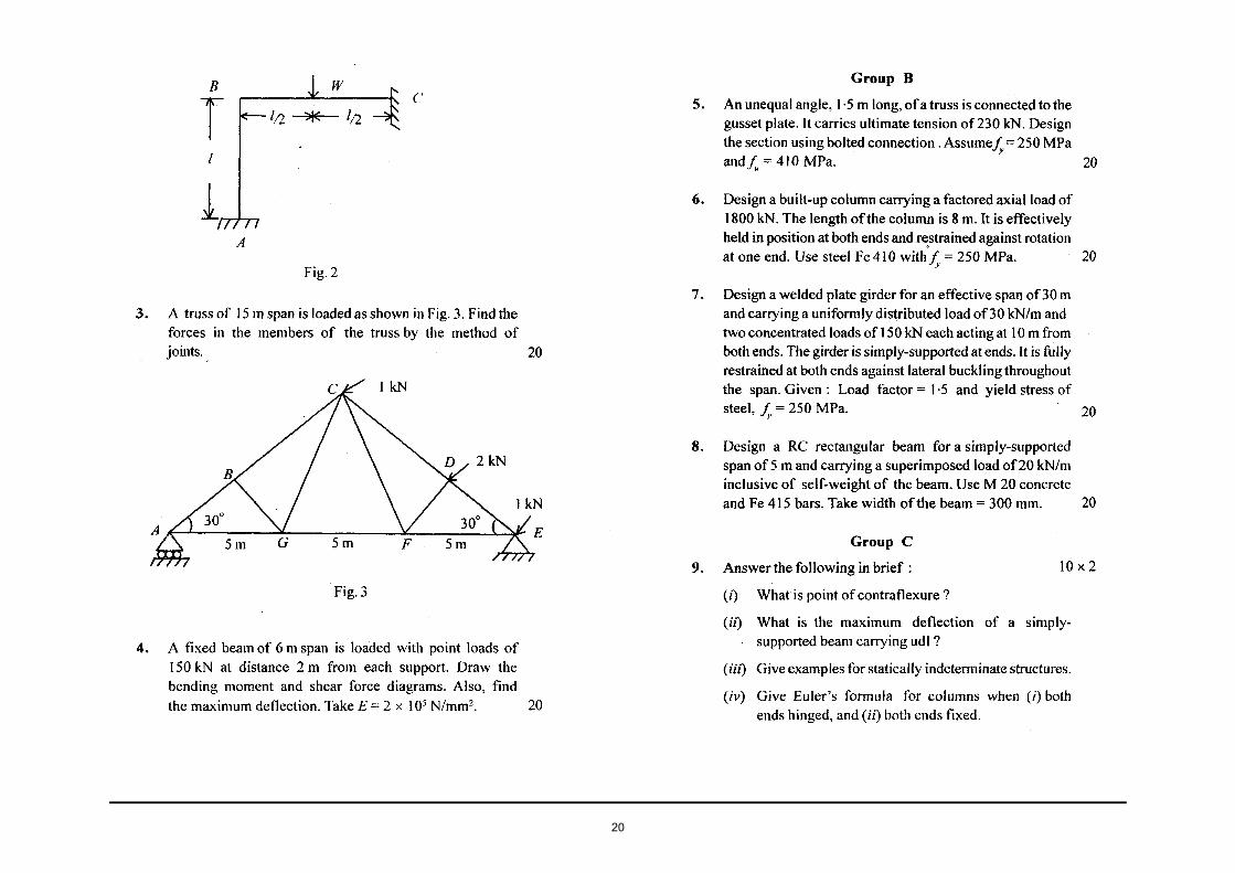
(b) A truss of 6 m span is loaded as shown in Fig. 5.
Determine the forces in the membersAB,BC, AG, DE,
EF and BG of the truss usjng method of joints. 15
4.
Fig. 5
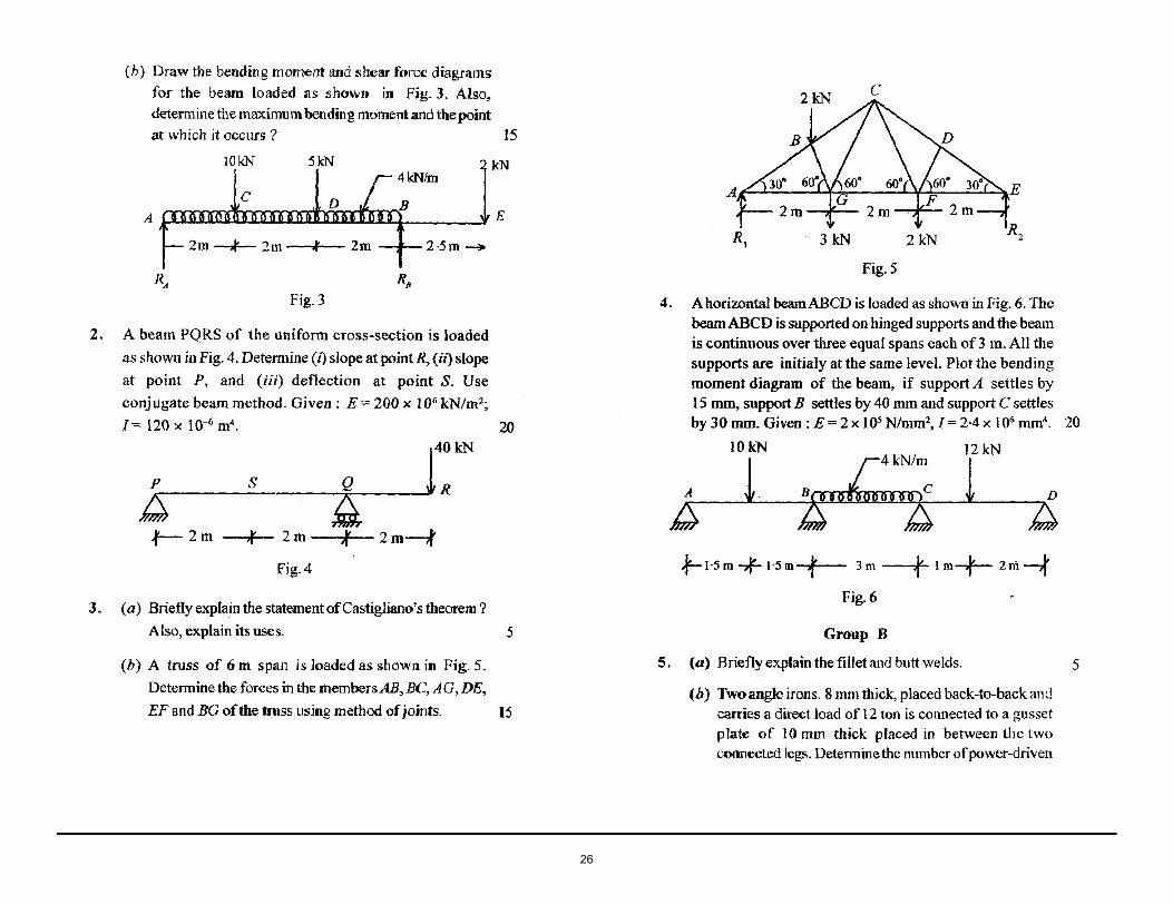
A horizontal beamABCD is loaded as shown in Fig. 6. The beam ABCD is supported on hinged supports and the beam is continuous over three equal spans each of 3 m. All the
supports are initialy at the same level. Plot the bending moment diagram of the beam, if support A settles by I 5 mm, support B settles by 40 mm and support C settles by 30 mm. Given: E=2 x l05 N/mm2, J=2·4x 106 mm4
• 20
lOkN 12 kN
~=~--l~---~~~0~.6:~::~~z~~~l--~~ }-1·5 m -,f- 1·5 m _,11r;...__ 3m ---.If~ Im-f- 2m--,j'
Fig.6
Group B
5. (a) Briefly explain the fillet and butt welds.
(b) Two angle irons. 8 mm thick, placed back-to-hack and carries a direct load of 12 ton is connected to a gusset plate of 10 mm thick placed in between the two connected legs. Determine the number of power-driven
5

27
field rivet 16 mm dia required for the joint? Assume shearing stress, F, = 945 kglcmz and bearing stress, Fbr = 2125 kglcmz. 5
(c) A 300 ISF 10 mm of grade Fe 410 is used as a tension member and connected to a 12 mm gusset plate by 20 mm dia bolts. Determine the effective net area of the member, if (i) chain bolting is done as shown in Fig. 7(a), and (ii) zig-zag bolting is done as shown in Fig. 7(b). 5 + 5
Fig. 7(a)
ANGLE
Fig. 7(b)
6. (a) Check the suitability of double angle section as shown in Fig. 8 for the continuous principle rafter of a tmss 2·5 m long between intermediate connectio11s. lt carries a thrust of20,000 kg. Assume allowable stress 1050 kg/cm2, thickness of gusset plate is l()mm.
Assume at least two rivets for the joints. Assume allowable stress in axial compression by referring Table 1. 10
GUSSET PLATE
·ISA
Fig.8
Table 1 :Allowable stress in axial compression
1/rRatio Allowable Stress, kg/cm1
50 1172 60 1130 70 1075 80 1007 90 928
(b) A beam of7·0 m effective span carries a uniformly distributed load of 1900 kg/m, including self-weight. The compression flange is held against lateral displacement. Assume allowable bending stress = 1650 kg/cm2
, allowable shearing stress= 945 kg/cm2• Check
the suitability ofbeam section ISLB 350@ 49·5 kg/m for the above beam. 10
7. (a) Briefly explain the procedure to design the plate girder'? 10

28
{b) Briefly explain the following : 2+2+3+3
{i) Load combinations to be considered in design of roof trusses
(ii) Slenderness ratio in compression members
(iiz) Web crippling and web buckling
(iv) Short column, intermediate column, and long column.
(a) Design the suitable slab base for a column having one ISHB 300 @ 63 kg!m and two cover plates of
350 mm x 25 mm as shown in Fig. 9. The column
carries an axialloa!f of 240 ton. Assume the permi-ssible bearing stress for.slab base= 1890 kglcm2• 10
il Projection (A) Projection (B)
!+-- 350mm .... ~
17 I .~ISA 25r ~, (IOOX IOOX 12
'----..., _,J
300mm +-ISHB300
1 @63kgfm
~ ' 25~ I _I
l .... _j I
Projection (A) ISA (lOOX 100 X 12) 17
Fig.9
(b) A RCC beam is 30 em wide and 70 em deep. The centres of steel are 5 em from the respective edges. Determine the area of steel in compression md tension zone for a bending moment of l ,300,000 kg.cm.
Assume the Limiting stress in concrete and steel are 50 kglcm2 and 1400 kglcm2, respectively. Given: Modular ratio (m) = 18. Note that RCC beam is reinforced on both sides.
lO
Group C
9. Answer the following in brief: 10 X 2
(i) Define 'statically indeterminate structure' and degree of indeterminacy.
(iz) Briefly explain the terms 'lap joint' and 'butt joint'.
(ii1) What do you mean by influence line?
(iv) Briefly explain the 'perfect frame' and 'imperfect frame'.
(v) Briefly explain the purpose of stiffeners in steel structures.
(vi) What are the advantages oftlie bolted connection over riveted connection ?
(vii) Briefly explain the efficiency of a joint in the steel structure.
(viii) Sketch/our important types of rolled steel structure shapes and label its various parts.
(ix) What do you mean by 'three hinged arches' ?
(x) Differentiate between under-reinforced and overreinforced sections for a RCC beam.