for ac compressors engine · pdf filefor ac compressors english engine jd4045hfc92 engine...
TRANSCRIPT

XAS 400 JD IT4 HOP
XATS 400 JD IT4 HOPXAVS 400 JD IT4 HOP
Instruction Manual for AC Compressors English
Engine JD4045HFC92
Engine JD4045HFC93


ATLAS COPCO - PORTABLE ENERGY DIVISIONwww.atlascopco.com
Instruction Manual for AC Compressor
XAS 400 JD IT4 HOPXATS 400 JD IT4 HOPXAVS 400 JD IT4 HOP
Printed matter Nr1310 3129 33
11/2012
Original instructions
Warranty and Liability Limitation
Use only authorized parts. Any damage or malfunction caused by the use of unauthorized parts iThe manufacturer does not accept any liability for any damage arisin made without the manufacturer's approval inwriting.Neglecting maintenance or making changes to the setup of the machi .While every effort has been made to ensure that the information in th e responsibility for possible errors.
Copyright 2012, Atlas Copco Compressors LLC, RockHill SC USA.
Any unauthorized use or copying of the contents or any part thereof is
- 4 -
s not covered by Warranty or Product Liability.g from modifications, additions or conversions
ne can result in major hazards, including fire riskis manual is correct, Atlas Copco does not assum
prohibited.

.8 Power ON / OFF ............................................... 34
.9 Starting .............................................................. 35
.10 Warming up....................................................... 35
.11 Loading ............................................................. 35
.12 Stopping ............................................................ 35
.13 Emergency stop................................................. 35
.14 Fault codes ........................................................ 36
Maintenance ............................................ 37Liability ............................................................ 37Service paks...................................................... 37Service kits ....................................................... 37Storage.............................................................. 37Preventive maintenance schedule..................... 38Maintenance schedule compressor ................... 38Oil specifications .............................................. 40
.1 Compressor oil .................................................. 41
.2 Engine oil .......................................................... 42Oil level check.................................................. 43
.1 Check engine oil level....................................... 43
.2 Check compressor oil level ............................... 43Oil and oil filter change.................................... 44
.1 Engine oil and oil filter change ......................... 44
.2 Compressor oil and oil filter change ................. 450 Compressor Oil Flushing Procedure ................ 460.1 Topping up the compressor oil.......................... 441 Coolant specifications ...................................... 471.1 PARCOOL EG.................................................. 471.2 Handling PARCOOL EG.................................. 482 Coolant check ................................................... 483 Topping up/replacing coolant........................... 483.1 Topping up without draining from
the cooling system............................................. 503.2 Topping up after limited quantity
draining from the cooling system...................... 503.3 Replacing the coolant........................................ 513.4 Cleaning coolers................................................ 514 Battery care....................................................... 514.1 Electrolyte ......................................................... 514.2 Activating a dry-charged battery....................... 514.3 Recharging a battery ......................................... 524.4 Battery maintenance.......................................... 52
- 5 -
PrefacePlease read the following instructions carefully beforestarting to use your compressor.It is a solid, safe and reliable machine, built according tothe latest technology. Follow the instructions in thisbooklet and we guarantee you years of troublefreeoperation.Always keep the manual available near the machine.In all correspondence always mention the compressortype and serial number, shown on the data plate.The company reserves the right to make changes withoutprior notice.
Table of contents
1 Safety precautions..................................... 71.1 Introduction ........................................................ 71.2 General safety precautions ................................. 81.3 Safety during transport and installation.............. 81.4 Safety during use and operation ......................... 91.5 Safety during maintenance and repair .............. 101.6 Tool applications safety.................................... 111.7 Specific safety precautions ............................... 11
2 Leading particulars ................................ 122.1 General description........................................... 12
3 Data Plate ................................................. 13
4 Main Parts ............................................... 144.1 Regulating system .............................................164.1.1 Overview.........................................................164.1.2 Air flow ............................................................ 174.1.3 Oil system......................................................... 174.1.4 Continuous pneumatic regulating
system............................................................... 184.2 Electric system.................................................. 194.3 Markings and information labels...................... 23
5 Operating instructions............................ 245.1 Parking, towing and lifting instructions ........... 245.1.1 Parking instructions.......................................... 245.1.2 Towing instructions.......................................... 245.1.3 Height adjustment ............................................ 245.1.4 Lifting instructions ........................................... 255.2 Starting / Stopping............................................ 265.3 Before starting .................................................. 265.3.1 Battery switch................................................... 275.3.2 Control panel .................................................... 285.3.3 Xc2002™ module ............................................ 285.3.4 Xc2002™ Menu Overview .............................. 295.3.5 Xc2002™ Menu Description ........................... 335.3.6 During operation .............................................. 345.3.7 Operations overview ........................................ 34
5.35.35.35.35.35.35.3
66.16.26.36.46.56.66.76.76.76.86.86.86.96.96.96.16.16.16.16.16.16.16.1
6.1
6.16.16.16.16.16.16.1

- 6 -
6.15 Compressor element overhaul .......................... 52
7 Adjustments and servicing procedures . 537.1 Adjustment of the continuous
pneumatic regulating system ............................ 537.2 Air filter engine/compressor............................. 557.2.1 Servicing ........................................................... 557.2.2 Main parts ......................................................... 557.2.3 Cleaning the dust trap ......................................557.2.4 Cleaning instructions filter element ..................557.2.5 Replacing the air filter element......................... 557.2.6 Air receiver ....................................................... 567.3 Safety valve ...................................................... 567.4 Exhaust Filter.................................................... 577.5 Fuel system....................................................... 587.5.1 Priming instructions .......................................... 587.5.2 Draining instructions......................................... 587.5.3 Filter replacement ............................................. 607.6 Brake adjustment .............................................. 607.6.1 Brake shoe adjustment ...................................... 607.6.2 Audit procedure of brake cable
adjustment ......................................................... 607.6.3 Brake cable adjustment ..................................... 607.6.4 Test procedure of brake cable
adjustment ......................................................... 60
8 Problem solving ....................................... 61
9 Available options ..................................... 63
10 Technical specifications .......................... 6410.1 Torque values ................................................... 6410.1.1 General torque values ....................................... 6410.1.2 Critical torque values ........................................ 6410.2 Compressor / engine specifications .................. 6410.2.1 Reference conditions......................................... 6410.2.2 Limitations ........................................................ 6610.2.3 Altitude unit performance curve ....................... 6510.2.4 Performance data .............................................. 6710.2.5 Design data........................................................ 69
11 Disposal..................................................... 69
11.1 General ............................................................. 6911.2 Disposal of materials ........................................ 70
12 Maintenance Log ..................................... 71

inary caution and due care required in handling,erating, maintenance or repair, also if not expresslyntioned in this instruction manual, is disclaimed bylas copco.e manufacturer does not accept any liability for anymage arising from the use of non-original parts and fordifications, additions or conversions made without thenufacturer’s approval in writing.any statement in this manual does not comply withal legislation, the stricter of the two shall be applied.tements in these safety precautions should not beerpreted as suggestions, recommendations orucements that it should be used in violation of any
plicable laws or regulations.
- 7 -
Safety precautions
INTRODUCTION
The policy of Atlas copco is to provide the users of theirequipment with safe, reliable and efficient products.Factors taken into account are among others:- the intended and predictable future use of the products, and
the environments in which they are expected to operate,- applicable rules, codes and regulations,- the expected useful product life, assuming proper service and
maintenance,- providing the manual with up-to-date information.Before handling any product, take time to read therelevant instruction manual. Besides giving detailedoperating instructions, it also gives specific informationabout safety, preventive maintenance, etc.Keep the manual always at the unit location, easyaccessible to the operating personnel.See also the safety precautions of the engine and possibleother equipment, which are separately sent along or arementioned on the equipment or parts of the unit.These safety precautions are general and some statementswill therefore not always apply to a particular unit.Only people that have the right skills should be allowed tooperate, adjust, perform maintenance or repair on Atlascopco equipment.It is the responsibility of management to appointoperators with the appropriate training and skill for eachcategory of job.Skill level 1: OperatorAn operator is trained in all aspects of operating the unitwith the push-buttons, and is trained to know the safetyaspects.Skill level 2: Mechanical technicianA mechanical technician is trained to operate the unit thesame as the operator. In addition, the mechanicaltechnician is also trained to perform maintenance andrepair, as described in the instruction manual, and isallowed to change settings of the control and safety
system. A mechanical technician does not work on liveelectrical components.Skill level 3: Electrical technicianAn electrical technician is trained and has the samequalifications as both the operator and the mechanicaltechnician. In addition, the electrical technician may carryout electrical repairs within the various enclosures of theunit. This includes work on live electrical components.Skill level 4: Specialist from the manufacturerThis is a skilled specialist sent by the manufacturer or itsagent to perform complex repairs or modifications to theequipment.In general it is recommended that not more than twopeople operate the unit, more operators could lead tounsafe operating conditions.Take necessary steps to keep unauthorized persons awayfrom the unit and eliminate all possible sources of dangerat the unit.When handling, operating, overhauling and/orperforming maintenance or repair on Atlas copcoequipment, the mechanics are expected to use safeengineering practices and to observe all relevant localsafety requirements and ordinances. The following list isa reminder of special safety directives and precautionsmainly applicable to Atlas copco equipment.These safety precautions apply to machinery processingor consuming air. Processing of any other gas requiresadditional safety precautions typical to the applicationand are not included herein.Neglecting the safety precautions may endanger people aswell as environment and machinery:- endanger people due to electrical, mechanical or chemical
influences,- endanger the environment due to leakage of oil, solvents or
other substances,- endanger the machinery due to function failures.All responsibility for any damage or injury resulting fromneglecting these precautions or by non-observance of
ordopmeAtThdamomaIf locStaintindap
To be read attentively and acted accordingly before towing, lifting, operating, performing maintenanceor repairing the compressor.

TY DURING TRANSPORT AND
ALLATION
towing, lifting or transporting the compressor inay, the battery switch must always be in the “OFF”n! a unit, all loose or pivoting parts, e.g. doors andr, shall first be securely fastened.t attach cables, chains or ropes directly to the liftingpply a crane hook or lifting shackle meeting localregulations. Never allow sharp bends in lifting
, chains or ropes.pter lifting is not allowed.trictly forbidden to dwell or stay in the risk zonea lifted load. Never lift the unit over people ortial areas. Lifting acceleration and retardatione kept within safe limits.ore towing the unit:scertain that the pressure vessel(s) is (are) depressurized,heck the towbar, the brake system and the towing eye.lso check the coupling of the towing vehicle,
heck the towing and brake capability of the towingehicle,heck that the towbar, jockey wheel or stand leg is safelyocked in the raised position,scertain that the towing eye can swivel freely on the hook,heck that the wheels are secure and that the tyres are inood condition and inflated correctly,onnect the signalisation cable and check all lightsttach the safety break-away cable or safety chain to theowing vehicle,emove wheel chocks, if applied, and disengage thearking brake.tow a unit use a towing vehicle of ample capacity.er to the documentation of the towing vehicle.
ver exceed the maximum towing speed of the unitnd the local regulations).ce the unit on level ground and apply the parkingke before disconnecting the unit from the towingicle. Unclip the safety break-away cable or safetyin. If the unit has no parking brake or jockey wheel,obilize the unit by placing chocks in front of and/
behind the wheels. When the towbar can beitioned vertically, the locking device must belied and kept in good order.
- 8 -
GENERAL SAFETY PRECAUTIONS1 The owner is responsible for maintaining the unit in a
safe operating condition. Unit parts and accessoriesmust be replaced if missing or unsuitable for safeoperation.
2 The supervisor, or the responsible person, shall at alltimes make sure that all instructions regardingmachinery and equipment operation and maintenanceare strictly followed and that the machines with allaccessories and safety devices, as well as theconsuming devices, are in good repair, free ofabnormal wear or abuse, and are not tampered with.
3 Whenever there is an indication or any suspicion thatan internal part of a machine is overheated, themachine shall be stopped but no inspection covers shallbe opened before sufficient cooling time has elapsed;this to avoid the risk of spontaneous ignition of oilvapour when air is admitted.
4 Normal ratings (pressures, temperatures, speeds, etc.)shall be durably marked.
5 Operate the unit only for the intended purpose andwithin its rated limits (pressure, temperature, speeds,etc.).
6 The machinery and equipment shall be kept clean, i.e.as free as possible from oil, dust or other deposits.
7 To prevent an increase in working temperature, inspectand clean heat transfer surfaces (cooler fins,intercoolers, water jackets, etc.) regularly. See thePreventive maintenance schedule.
8 All regulating and safety devices shall be maintainedwith due care to ensure that they function properly.They may not be put out of action.
9 Care shall be taken to avoid damage to safety valvesand other pressure-relief devices, especially to avoidplugging by paint, oil coke or dirt accumulation, whichcould interfere with the functioning of the device.
10 Pressure and temperature gauges shall be checkedregularly with regard to their accuracy. They shall bereplaced whenever outside acceptable tolerances.
11 Safety devices shall be tested as described in themaintenance schedule of the instruction manual todetermine that they are in good operating condition.See the Preventive maintenance schedule.
12 Mind the markings and information labels on the unit.13 In the event the safety labels are damaged or destroyed,
they must be replaced to ensure operator safety.
14 Keep the work area neet. Lack of order will increasethe risk of accidents.
15 When working on the unit, wear safety clothing.Depending on the kind of activities these are: safetyglasses, ear protection, safety helmet (including visor),safety gloves, protective clothing, safety shoes. Do notwear the hair long and loose (protect long hair with ahairnet), or wear loose clothing or jewelry.
16 Take precautions against fire. Handle fuel, oil and anti-freeze with care because they are inflammablesubstances. Do not smoke or approach with nakedflame when handling such substances. Keep a fire-extinguisher in the vicinity.
SAFE
INST
When any wpositioTo lifttowbaDo noeye; asafety cablesHelicoIt is sunder residenshall b1 Bef
- a- c
A- c
v- c
l- a- c
g- c- a
t- r
p2 To
Ref3 Ne
(mi4 Pla
bravehchaimmor posapp

connections.If the compressor is to be used for sand-blasting or willbe connected to a common compressed-air system, fitan appropriate non-return valve (check valve) betweencompressor outlet and the connected sand-blasting orcompressed-air system. Observe the right mountingposition/direction.Before removing the oil filler plug, ensure that thepressure is released by opening an air outlet valve.Never remove a filler cap of the cooling water systemof a hot engine. Wait until the engine has sufficientlycooled down.Never refill fuel while the unit is running, unlessotherwise stated in the Atlas copco Instruction Book(AIB). Keep fuel away from hot parts such as air outletpipes or the engine exhaust. Do not smoke whenfuelling. When fuelling from an automatic pump, anearthing cable should be connected to the unit todischarge static electricity. Never spill nor leave oil,fuel, coolant or cleansing agent in or around the unit.All doors shall be shut during operation so as not todisturb the cooling air flow inside the bodywork and/orrender the silencing less effective. A door should bekept open for a short period only e.g. for inspection oradjustment.Periodically carry out maintenance works according tothe maintenance schedule.Stationary housing guards are provided on all rotatingor reciprocating parts not otherwise protected andwhich may be hazardous to personnel. Machinery shallnever be put into operation, when such guards havebeen removed, before the guards are securelyreinstalled.Noise, even at reasonable levels, can cause irritationand disturbance which, over a long period of time, maycause severe injuries to the nervous system of humanbeings. When the sound pressure level, at any pointwhere personnel normally has to attend, is:- below 70 dB(A): no action needs to be taken,- above 70 dB(A): noise-protective devices should be
provided for people continuously being present in theroom,
- below 85 dB(A): no action needs to be taken for occasionalvisitors staying a limited time only,
- above 85 dB(A): room to be classified as a noise-hazardous area and an obvious warning shall be placedpermanently at each entrance to alert people entering the
- 9 -
5 To lift heavy parts, a hoist of ample capacity, tested andapproved according to local safety regulations, shall beused.
6 Lifting hooks, eyes, shackles, etc., shall never be bentand shall only have stress in line with their design loadaxis. The capacity of a lifting device diminishes whenthe lifting force is applied at an angle to its load axis.
7 For maximum safety and efficiency of the liftingapparatus all lifting members shall be applied as near toperpendicular as possible. If required, a lifting beamshall be applied between hoist and load.
8 Never leave a load hanging on a hoist.9 A hoist has to be installed in such a way that the object
will be lifted perpendicular. If that is not possible, thenecessary precautions must be taken to prevent load-swinging, e.g. by using two hoists, each atapproximately the same angle not exceeding 30° fromthe vertical.
10 Locate the unit away from walls. Take all precautionsto ensure that hot air exhausted from the engine anddriven machine cooling systems cannot berecirculated. If such hot air is taken in by the engine ordriven machine cooling fan, this may causeoverheating of the unit; if taken in for combustion, theengine power will be reduced.
11 Before moving the compressor, switch it off.12 If the warning light on the ABS module or in the
vehicle lights up, please contact Atlas copco.
SAFETY DURING USE AND OPERATION1 When the unit has to operate in a fire-hazardous
environment, each engine exhaust has to be providedwith a spark arrestor to trap incendiary sparks.
2 The exhaust contains carbon monoxide which is alethal gas. When the unit is used in a confined space,conduct the engine exhaust to the outside atmosphereby a pipe of sufficient diameter; do this in such a waythat no extra back pressure is created for the engine. Ifnecessary, install an extractor. Observe any existinglocal regulations. Make sure that the unit has sufficientair intake for operation. If necessary, install extra airintake ducts.
3 When operating in a dust-laden atmosphere, place theunit so that dust is not carried towards it by the wind.Operation in clean surroundings considerably extendsthe intervals for cleaning the air intake filters and thecores of the coolers.
4 Close the compressor air outlet valve beforeconnecting or disconnecting a hose. Ascertain that ahose is fully depressurized before disconnecting it.Before blowing compressed air through a hose or airline, ensure that the open end is held securely, so that itcannot whip and cause injury.
5 The air line end connected to the outlet valve must besafeguarded with a safety cable, attached next to thevalve.
6 No external force may be exerted on the air outletvalves, e.g. by pulling on hoses or by installingauxiliary equipment directly to a valve, e.g. a waterseparator, a lubricator, etc. Do not step on the air outletvalves.
7 Never move a unit when external lines or hoses areconnected to the outlet valves, to avoid damage tovalves, manifold and hoses.
8 Do not use compressed air from any type ofcompressor, without taking extra measures, forbreathing purposes as this may result in injury or death.For breathing air quality, the compressed air must beadequately purified according to local legislation andstandards. Breathing air must always be supplied atstable, suitable pressure.
9 Distribution pipework and air hoses must be of correctdiameter and suitable for the working pressure. Neveruse frayed, damaged or deteriorated hoses. Replacehoses and flexibles before the lifetime expires. Useonly the correct type and size of hose end fittings and
10
11
12
13
14
15
16
17
rying out such operations. Never weld on, or in anyy modify, pressure vessels. Disconnect thernator cables during arc welding on the unit.port the towbar and the axle(s) securely if workingerneath the unit or when removing a wheel. Do not on jacks.
not remove any of, or tamper with, the sound-ping material. Keep the material free of dirt andids such as fuel, oil and cleansing agents. If anynd-damping material is damaged, replace it tovent the sound pressure level from increasing. only lubricating oils and greases recommended orroved by Atlas copco or the machine manufacturer.ertain that the selected lubricants comply with alllicable safety regulations, especially with regard tolosion or fire-risk and the possibility ofomposition or generation of hazardous gases.ver mix synthetic with mineral oil.tect the engine, alternator, air intake filter, electrical regulating components, etc., to prevent moistureress, e.g. when steam-cleaning.en performing any operation involving heat, flames
sparks on a machine, the surrounding componentsll first be screened with non-flammable material.ver use a light source with open flame for inspecting interior of a machine.connect –battery-clamp before starting electricalvicing or welding (or turn battery-switch in “off”ition).en repair has been completed, the machine shall bered over at least one revolution for reciprocatingchines, several revolutions for rotary ones to ensuret there is no mechanical interference within thechine or driver. Check the direction of rotation ofctric motors when starting up the machine initially after any alteration to the electrical connection(s)
switch gear, to check that the oil pump and the fanction properly.intenance and repair work should be recorded in anrator’s logbook for all machinery. Frequency andure of repairs can reveal unsafe conditions.en hot parts have to be handled, e.g. shrink fitting,cial heat-resistant gloves shall be used and, ifuired, other body protection shall be applied.en using cartridge type breathing filter equipment,ertain that the correct type of cartridge is used andt its useful service life is not surpassed.
- 10 -
room, for even relatively short times, about the need towear ear protectors,
- above 95 dB(A): the warning(s) at the entrance(s) shall becompleted with the recommendation that also occasionalvisitors shall wear ear protectors,
- above 105 dB(A): special ear protectors that are adequatefor this noise level and the spectral composition of thenoise shall be provided and a special warning to that effectshall be placed at each entrance.
18 The unit has parts, which may be accidentally touchedby personnel, of which the temperature can be in exessof 80 °C (176 °F). The insulation or safety guard,protecting these parts shall not be removed before theparts have cooled down to room temperature.
19 Never operate the unit in surroundings where there is apossibility of taking in flammable or toxic fumes.
20 If the working process produces fumes, dust orvibration hazards, etc., take the necessary steps toeliminate the risk of personnel injury.
21 When using compressed air or inert gas to clean downequipment, do so with caution and use the appropriateprotection, at least safety glasses, for the operator aswell as for any bystander. Do not apply compressed airor inert gas to your skin or direct an air or gas stream atpeople. Never use it to clean dirt from your clothes.
22 When washing parts in or with a cleaning solvent,provide the required ventilation and use appropriateprotection such as a breathing filter, safety glasses,rubber apron and gloves, etc.
23 Safety shoes should be compulsory in any workshopand if there is a risk, however small, of falling objects,wearing of a safety helmet should be included.
24 If there is a risk of inhaling hazardous gases, fumes ordust, the respiratory organs must be protected anddepending on the nature of the hazard, so must the eyesand skin.
25 Remember that where there is visible dust, the finer,invisible particles will almost certainly be present too;but the fact that no dust can be seen is not a reliableindication that dangerous, invisible dust is not presentin the air.
26 Never operate the unit at pressures or speeds below orin excess of its limits as indicated in the technicalspecifications.
27 Do not use aerosol types of starting aids such as ether.Such use could result in an explosion and personalinjury.
SAFETY DURING MAINTENANCE AND
REPAIR
Maintenance, overhaul and repair work shall only becarried out by adequately trained personnel; if required,under supervision of someone qualified for the job.1 Use only the correct tools for maintenance and repair
work, and only tools which are in good condition.2 Parts shall only be replaced by genuine Atlas copco
replacement parts.3 All maintenance work, other than routine attention,
shall only be undertaken when the unit is stopped.Steps shall be taken to prevent inadvertent starting. Inaddition, a warning sign bearing a legend such as”work in progress; do not start” shall be attached to thestarting equipment. On engine-driven units the batteryshall be disconnected and removed or the terminalscovered by insulating caps. On electrically driven unitsthe main switch shall be locked in open position andthe fuses shall be taken out. A warning sign bearing alegend such as ”work in progress; do not supplyvoltage” shall be attached to the fuse box or mainswitch.
4 Before dismantling any pressurized component, thecompressor or equipment shall be effectively isolatedfrom all sources of pressure and the entire system shallbe relieved of pressure. Do not rely on non-returnvalves (check valves) to isolate pressure systems. Inaddition, a warning sign bearing a legend such as”work in progress; do not open” shall be attached toeach of the outlet valves.
5 Prior to stripping an engine or other machine orundertaking major overhaul on it, prevent all movableparts from rolling over or moving.
6 Make sure that no tools, loose parts or rags are left inor on the machine. Never leave rags or loose clothingnear the engine air intake.
7 Never use flammable solvents for cleaning (fire-risk).8 Take safety precautions against toxic vapours of
cleaning liquids.9 Never use machine parts as a climbing aid.10 Observe scrupulous cleanliness during maintenance
and repair. Keep away dirt, cover the parts and exposedopenings with a clean cloth, paper or tape.
11 Never weld on or perform any operation involving heatnear the fuel or oil systems. Fuel and oil tanks must becompletely purged, e.g. by steam-cleaning, before
carwaalte
12 Supundrely
13 Dodamliqusoupre
14 UseappAscappexpdecNe
15 Proanding
16 Whor sha
17 Nethe
18 Disserpos
19 Whbarmathamaeleandor fun
20 Maopenat
21 Whspereq
22 Whasctha
to those vessel walls which are exposed to pressure.The vessel is provided and may only be used with therequired safety equipment such as manometer,overpressure control devices, safety valve, etc.Draining of condensate shall be performed daily whenvessel is in use.
Installation, design and connections should not be changed.Bolts of cover and flanges may not be used for extra fixation.
fety valveserating & Maintenancely trained and technically competent personnel should
nsider overhaul, re-set or performance testing of safetylves.e safety valve is supplied with either a lead securityl or crimped cover to deter unauthorised access to thessure regulation device.der no circumstances should the set pressure of theety valve be altered to a different pressure than thatmped on the valve without the permission of thetallation designer.the set pressure must be altered then use only correctrts supplied by Atlas copco and in accordance with thetructions available for the valve type.fety valves must be frequently tested and regularlyintained.e set pressure should be periodically checked foruracy.
hen fitted, the compressors should be operated atssures not less than 75% of the set pressure to ensuree and easy movement of internal parts.e frequency of tests is influenced by factors such as theerity of the operating environment and aggressiveness
the pressurised medium.ft seals and springs should be replaced as part of theintenance procedure. not paint or coat the installed safety valve (see alsoventive maintenance schedule).
- 11 -
23 Make sure that oil, solvents and other substances likelyto pollute the environment are properly disposed of.
24 Before clearing the unit for use after maintenance oroverhaul, check that operating pressures, temperaturesand speeds are correct and that the control andshutdown devices function correctly.
TOOL APPLICATIONS SAFETY
Apply the proper tool for each job. With the knowledge ofcorrect tool use and knowing the limitations of tools,along with some common sense, many accidents can beprevented.Special service tools are available for specific jobs andshould be used when recommended. The use of thesetools will save time and prevent damage to parts.
SPECIFIC SAFETY PRECAUTIONS
BatteriesWhen servicing batteries, always wear protectingclothing and glasses.1 The electrolyte in batteries is a sulphuric acid solution
which is fatal if it hits your eyes, and which can causeburns if it contacts your skin. Therefore, be carefulwhen handling batteries, e.g. when checking the chargecondition.
2 Install a sign prohibiting fire, open flame and smokingat the post where batteries are being charged.
3 When batteries are being charged, an explosive gasmixture forms in the cells and might escape through thevent holes in the plugs. Thus an explosive atmospheremay form around the battery if ventilation is poor, andcan remain in and around the battery for several hoursafter it has been charged. Therefore:- never smoke near batteries being, or having recently been,
charged,- never break live circuits at battery terminals, because a
spark usually occurs.4 When connecting an auxiliary battery (AB) in parallel
to the unit battery (CB) with booster cables: connectthe + pole of AB to the + pole of CB, then connect the- pole of CB to the mass of the unit. Disconnect in thereverse order.
Pressure vesselsMaintenance/installation requirements:1 The vessel can be used as pressure vessel or as
separator and is designed to hold compressed air for thefollowing application:- pressure vessel for compressor,- medium AIR/OIL,and operates as detailed on the data plate of the vessel:- the maximum working pressure ps in bar (psi),- the maximum working temperature Tmax in °C (°F),- the minimum working temperature Tmin in °C (°F),- the capacity of the vessel V in l (US gal).
2 The pressure vessel is only to be used for theapplications as specified above and in accordance withthe technical specifications. Safety reasons prohibitany other applications.
3 National legislation requirements with respect to re-inspection must be complied with.
4 No welding or heat treatment of any kind is permitted
5
6
7.
8.
SaOpOncovaThseapreUnsafstainsIf painsSamaThaccWprefreThsevof SomaDoPre

gine is equipped with low oil pressure and hight temperature shut-down sensors.ectric system is equipped with a 12V main switch.
e and axlesmpressor/engine unit is supported by rubber buffersframe.andard compressor has fixed towbar with brakes.
workdywork has openings at the shaped front and rearr the intake and outlet of cooling air and hingedfor maintenance and service operations. Theork is internally lined with sound-absorbingal.
g eyeng eye is accessible when a small door at the top ofit is unlocked.
ol panelntrol panel grouping the air pressure gauge, control etc., is placed at the right hand/ rear end corner.
st filter systemhaust system includes a new exhaust aftertreatment that meets strict installation standards and includesl particulate filter.
- 12 -
Leading particulars
General description
The XAS 400 JD7 IT4 is a silenced, single-stage, oil-injected screw compressor, built for a nominal effectiveworking pressure of 7 bar (100 psi).The XATS 400 JD7 IT4 is a silenced, single-stage, oil-injected screw compressor, built for a nominal effectiveworking pressure of 10 bar (145.04 psi).The XAVS 400 JD7 IT4 is a silenced, single-stage, oil-injected screw compressor, built for a nominal effectiveworking pressure of 14 bar (203.05 psi).All machines meet Tier 4I / Stage IIIB emission standards.
EngineThe compressors XAS 400 JD7 IT4, XATS 400 JD7 IT4and XAVS 400 JD7 IT4 is driven by 4 cylinder in-lineliquid-cooled diesel engines.The engine’s power is transmitted to the compressorelement through a heavy-duty coupling.
CompressorThe compressor casing houses two screw-type rotors,mounted on ball and roller bearings. The male rotor,driven by the engine, drives the female rotor. Thecompressor delivers pulsation-free air.
Injected oil is used for sealing, cooling and lubricatingpurposes.
Compressor oil systemThe oil is boosted by air pressure. The system has no oilpump.The oil is removed from the air, in the air/oil vessel at firstby centrifugal force, secondly through the oil separatorelement.The vessel is provided with an oil level indicator.
RegulationThe compressor is provided with a continuous regulatingsystem and a blow-off valve which is integrated in theunloader assembly. The valve is closed during operationby air receiver pressure and opens by air receiver pressurevia the compressor element when the compressor isstopped.When the air consumption increases, the air receiverpressure will decrease and vice versa.This receiver pressure variation is sensed by the regulatingvalve which, by means of control air to the unloader andan electronic engine speed regulator, matches the airoutput to the air consumption. The air receiver pressure ismaintained between the pre-selected working pressure andthe corresponding unloading pressure.
Cooling systemThe engine is provided with a liquid-cooler andintercooler and the compressor is provided with an oilcooler. For available options see chapter Availableoptions.The cooling air is generated by a fan, driven by the engine.
Safety devicesA thermal shut-down sensor protects the compressoragainst overheating. The air receiver is provided with asafety valve.
The encoolanThe el
FramThe coin the The st
BodyThe boend fodoors bodywmateri
LiftinA liftithe un
ContrThe coswitch
ExhauThe exsystema diese

- 13 -
Data plateThe compressor is furnished with a data plate showing themodel, product number and max. final proposal.
Serial number
The serial number (SN) is mentioned on the date plate.Last 6 digits from V.I.N.(Vehicle Identification Number)is serial number.
- 14 -
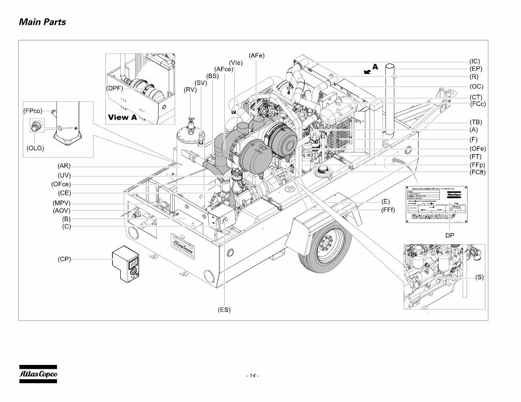
Main Parts

- 15 -
Reference NameA AlternatorAFce Air Filter (compressor element)AFe Air Filter (engine)AOV Air Outlet ValvesAR Air ReceiverB BatteryBS Battery SwitchCE Compressor ElementC CubicleCP Control PanelCT Coolant TankDp Data plateE EngineEP Exhaust PipeES Emergency StopF FanFCft Filler Cap (fuel tank)FCc Filler Cap (coolant)FFf Fuel Filter finalFFp Fuel Filter primaryFPco Filler Plug (oil compressor element)FT Fuel TankIC IntercoolerJW Jockey WheelMPV Minimum Pressure ValveOC Oil CoolerOFce Oil Filter (compressor element)OFe Oil Filter (engine)OSV+CV Oil stop Valve + Check ValveOLG Oil Level GaugeR RadiatorRV Regulating ValveS Starter
Reference NameSoV Solenoid ValveSV Safety ValveTB TowbarUV Unloading ValveVIe Vaccum Indicator EngineDPF Diesel Particle Filter

- 16 -
REGULATING SYSTEM
Overview
- 17 -
AIR FLOWAir drawn through the airfilter (AFce) into the compressorelement (CE) is compressed. At the element outlet,compressed air and oil pass into the air receiver/oilseparator (AR/OS).The check valve (CV) prevents blow-back of compressedair when the compressor is stopped. In the air receiver/oilseparator (AR/OS), most of the oil is removed from theair/oil mixture.The oil collects in the receiver and on the bottom of theseparator element.The air leaves the receiver via a minimum pressure valve(MPV) which prevents the receiver pressure fromdropping below the minimum working pressure, evenwhen the air outlet valves are open (specified in sectionLimitation). This ensures adequate oil injection andprevents oil consumption. The minimum pressure valve(MPV) also functions as a check valve.The system comprises temperature sensors (TS),regulating pressure sensors (RPS) and a working pressuresensor (WPS).
OIL SYSTEMThe lower part of the air receiver (AR) serves as oil tank.Air pressure forces the oil from the air receiver/oilseparator (AR/OS) through the oil cooler (OC), the oilfilters (OFc) and the oil stop valve (OSV) to thecompressor element (CE).When the compressor is stopped and / or there is nopressure in the system, the oil stop valve (OSV) preventsthe oil from flowing back into the compressor element.The thermostatic by-pass valve (TBV) starts openingwhen the oil temperature is 70 °C (158 °F).The compressor element has an oil gallery in the bottom ofits casing. The oil for rotor lubrication, cooling and sealingis injected through holes in the gallery.Lubrication of the bearings is ensured by oil injected intothe bearing housings.The injected oil, mixed with the compressed air, leaves thecompressor element and re-enters the air receiver, where itis separated from the air as described in section Air flow.The oil that collects in the bottom of the oil separatorelement is returned to the system through a scavengingline (SL), which is provided with a flow restrictor.The oil filter by-pass valve opens when the pressure dropover the filter is above normal because of a clogged filter.The oil then by-passes the filter without being filtered. Forthis reason, the oil filter must be replaced at regularintervals (see section Preventive maintenance schedule).
cludes a fuel burner in the exhaust stream thatittently raises the temperature above 600º C / F. regeneration decreases in the higher load cycles of
mpressor.
4 ASH REMOVALves in lube oil that do not combust duringration, turn into ash. This reduces filter volume,ion efficiency and backpressure.ust be removed mechanically, according a servicel, either by washing or blowing it out. This servicel can be increased depending on duty cycle.
- 18 -
CONTINUOUS PNEUMATIC REGULATING SYSTEMThe compressor is provided with a continuous pneumaticregulating system and a blow-off valve (BOV) which isintegrated in the unloader assembly (UA). The valve isclosed during operation by outlet pressure of thecompressor element and opens by air receiver pressurewhen the compressor is stopped.When the air consumption increases, the air receiverpressure will decrease and vice versa. This receiverpressure variation is sensed by the regulating valve (RV)which, by means of control air to the unloader assembly(UA), matches the air output to the air consumption. Theair receiver pressure is maintained between the pre-selected working pressure and the correspondingunloading pressure.When starting the compressor, the throttle valve is keptclosed via receiver pressure. The compressor element(CE) takes in air and pressure builds up in the receiver(AR). The throttle valve is closed. The air output iscontrolled from maximum output (100%) to no output(0%) by:1. Speed control of the engine between maximum load
speed and unloading speed (the output of a screw compressor is proportional to the rotating speed).
2. Air inlet throttling.If the air consumption is equal to or exceeds the maximumair output, the engine speed is held at maximum load speedand the throttle valve is fully open.If the air consumption is less than the maximum air output,air receiver pressure increases and the regulating valvesupplies control air to throttle valve to reduce the airoutput and holds air receiver pressure between the normalworking pressure and the corresponding unloadingpressure. Unloading pressure = normal working pressure +1.5 to 2 bar (22 to 29 psi).When the air consumption is resumed, the blow off valve(BOV) closes and the throttle valve gradually opens the airintake and the electronic speed regulator increases theengine speed.
The construction of the regulating valve (RV) is such thatany increase (decrease) of the air receiver pressure abovethe pre-set valve opening pressure results in a proportionalincrease (decrease) of the control pressure to the throttlevalve and the electronic speed regulator.Part of the control air is vented to atmosphere, and anycondensate discharged, through the vent holes.
EXHAUST GAS AFTERTREATMENTTo meet the demands of EPA Tier4a/ EU Stage IIIBEmission Legislation, the engine is equipped with anexhaust gas recirculation system and a particulate filter.The exhaust gas is fully automatically cleaned. Theprocess is monitored by the Xc2002 machinecontroller.
STEP 1 EXHAUST GAS RECIRCULATIONWith Exhaust Gas Recirculation (EGR), part of theexhaust gases are cooled and then injected back into theengine cylinders to reduce NOx.Exhaust gas is cooled to allow the introduction of a greatermass of recirculated gas.The outcome is a lower peak combustion temperature.
STEP 2 DIESEL PARTICULATE FILTER + DIESEL OXIDATION CATALYSTTo remove excess particulate matter from the exhaust gas,a Diesel Particulate Filter (DPF) is used. This systemconsists of a Diesel Oxidation Catalyst (DOC) and a filtermodule. The DOC reduces CO, HC and NO throughoxidation. It also produces NO2 to regenerate the DPF.The filter system removes 99% of particulate matter.
STEP 3 ACTIVE REGENERATIONParticulate matter left in the filter system is burned in aprocess called regeneration. Extending the.lifetime of afilter, it converts particulate matter into CO2 and ash.Atlas Copco engines use high temperature regeneration
that ininterm1100°Activethe co
STEPAdditiregeneoxidatAsh mintervainterva

- 19 -
ELECTRIC SYSTEM
Circuit diagram Size XAS 400 IT4 (John Deere engine) - part 1 (1310 3200 26)

- 20 -
Reference NameF1 : a3 Circuit Breaker 15AF2 : a3 Circuit Breaker 30AF3 : a3 Circuit Breaker 40AG1 : d2 BatteryK0 : f3 Start RelayLS1 : g5 Level Switch - Coolant levelLT1 : g6 Level Sensor - Fuel LevelM1 : f2-f3 Starter MotorN1 : d5-e6 Control Module - Xc2002PS1 : g4 Pressure Switch - AirfilterPT1 : g6 Pressure Sensor - Regulating PressureS0 : d2 Battery SwitchS1 : b3 Main Power SwitchS2 : b3 Emergency StopTS1 : g6 Temperature Switch
Compressor Element TemperatureY1 : g4 Loading Valve
A Communication portB To machine type specific diagrams
Reference Name1 CAN-L CAN LOW2 CAN-GND CAN Shield3 CAN-H CAN High4 GND Common for 5..7 (GND)12 COM Common for 13..18 (12Vdc)14 DI-02 ON23 Common for 24, 25, 32 (12Vdc)25 NO Loading Valve26 GND (Batt-)27 12/24 Vdc (Batt+)32 R3 NO Start Relay Output33 COM R4 Common for 34 (12Vdc)34 R4 NO Power After Contact35 COM R5 Common for 35 (12Vdc)36 R5 NO ON contact38 5Vdc Sensor Supply (5Vdc)40 AI-03 Vessel Pressure41 AI-01 Regulating Pressure43 GND Sensor GND49 AI-02 Fuel Level54 PT1000-01 Element temperature

- 21 -
Circuit diagram Size XAS 400 IT4 (John Deere engine) - part 2(1310 3200 26)

- 22 -
Reference NameF4 Circuit Breaker 15AF5 Circuit Breaker 15AF6 Circuit Breaker 50AG2 AlternatorK1 Relay - Starter MotorN1 Control module - Xc2002N2 Variable Speed Fan Connector
(OPTIONAL)N3 Oil Cooler Temp Connector
(OPTIONAL)N4 Electronic Control Unit - EngineN5 Engine Diagnostic ConnectorN6 Can Termination ResistorN7 Auxillary ConnectorN8 After Treatment Temp ConnectorN9 DPF Pressure Sensor ConnectorR3 Grid/Glow plug heaterC CAN shieldB CAN lowN7A Switched Power
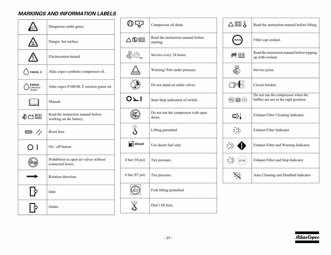
Read the instruction manual before lifting.
Filler cap coolant.
Read the instruction manual before topping up with coolant.
Service point.
Circuit breaker.
Do not run the compressor when the baffles are not in the right position.
Exhaust Filter Cleaning Indicator
Exhaust Filter Indicator
Exhaust Filter and Warning Indicator
Exhaust Filter and Stop Indicator
Auto Cleaning and Disabled Indicator
- 23 -
MARKINGS AND INFORMATION LABELS
Dangerous outlet gases.
Danger, hot surface.
Electrocution hazard.
Atlas copco synthetic compressor oil.
Atlas copco PAROIL E mission green oil.
Manual.
Read the instruction manual before working on the battery.
Reset fuse.
On / off button.
Prohibition to open air valves without connected hoses.
Rotation direction.
Inlet.
Outlet.
Compressor oil drain.
Read the instruction manual before starting.
Service every 24 hours.
Warning! Part under pressure.
Do not stand on outlet valves.
Start-Stop indication of switch.
Do not run the compressor with open doors.
Lifting permitted.
Use diesel fuel only.
Tire pressure.
Tire pressure.
Fork lifting permitted.
Don’t lift here.
4 bar (58 psi)
6 bar (87 psi)

ING INSTRUCTIONS
t breakaway cable (1) to the vehicle.Secure jockey(2) in the highest possible position. The jockeyis prevented from turning.
wing position of jockey wheel
Before towing the compressor, ensure thatthe towing equipment of the vehiclematches the towing eye or ball connector.The towbar should be as level as possibleand the compressor and towing eye end in alevel position.
Before moving the compressor, switch it off.Never move the compressor with air hosesconnected to the air outlet valves.
- 24 -
Operating instructions
PARKING, TOWING AND LIFTING
INSTRUCTIONS
Safety precautions
Attention
PARKING INSTRUCTIONS
Fixed towbar with jockey wheel and brakes
When parking a compressor, secure the jockey wheel (1)to support the compressor in a level position. Place thecompressor as level as possible; however, it can beoperated temporarily in an out-of-level position notexceeding 15°. If the compressor is parked on slopingground, immobilize the compressor by placing wheelchocks (available as option) in front of or behind thewheels.
Rear-end of compressor upwind
Locate the rear-end of the compressor upwind, away fromcontaminated wind-streams and walls. Avoid recirculationof exhaust air from the engine. This can cause overheatingand engine power decrease.
TOW
connecwheel wheel
To
The operator is expected to apply allrelevant Safety precautions.
Before putting the compressor in to use,check the brake system as described insection Brake shoe adjustment.After the first 50 miles travel:Check and retighten the wheel nuts andtowbar bolts to the specified torque. Seesection Compressor / engine specifications.Check the brake adjustment. See sectionBrake shoe adjustment.
When towing, lifting or transporting thecompressor in any way, the battery switchmust always be in the “OFF” position!
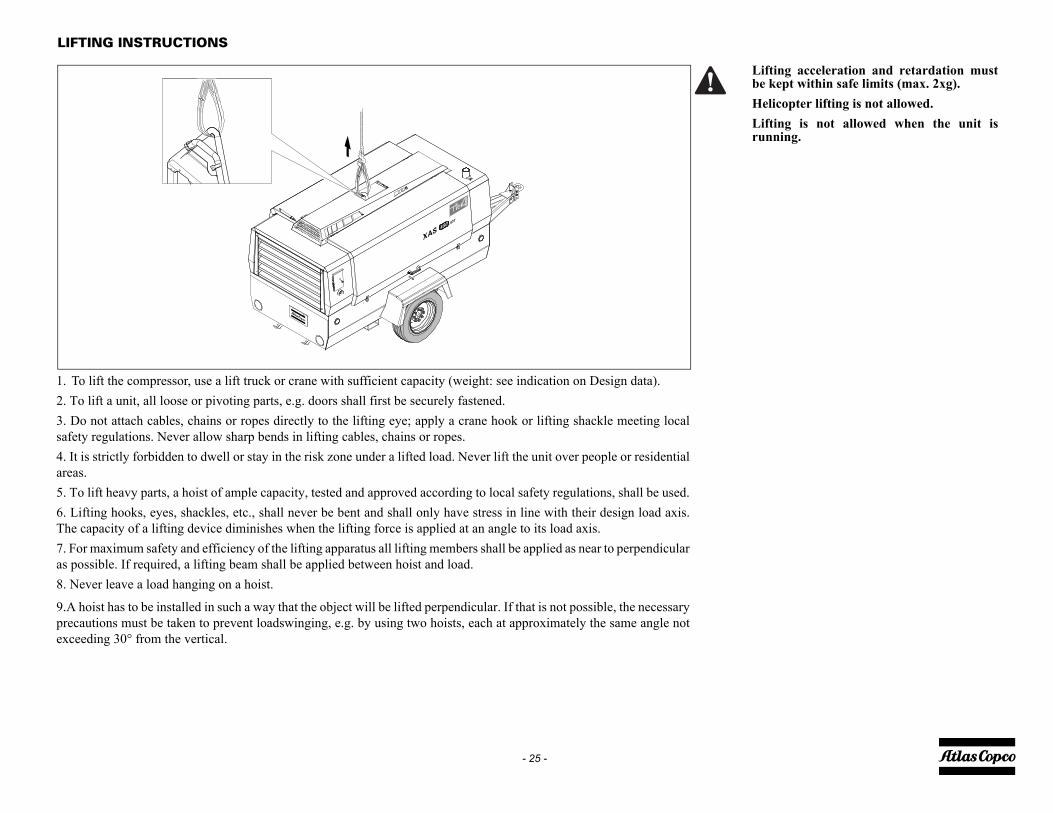
Lifting acceleration and retardation mustbe kept within safe limits (max. 2xg).Helicopter lifting is not allowed.Lifting is not allowed when the unit isrunning.
- 25 -
LIFTING INSTRUCTIONS
1. To lift the compressor, use a lift truck or crane with sufficient capacity (weight: see indication on Design data).2. To lift a unit, all loose or pivoting parts, e.g. doors shall first be securely fastened.3. Do not attach cables, chains or ropes directly to the lifting eye; apply a crane hook or lifting shackle meeting localsafety regulations. Never allow sharp bends in lifting cables, chains or ropes.4. It is strictly forbidden to dwell or stay in the risk zone under a lifted load. Never lift the unit over people or residentialareas.5. To lift heavy parts, a hoist of ample capacity, tested and approved according to local safety regulations, shall be used.6. Lifting hooks, eyes, shackles, etc., shall never be bent and shall only have stress in line with their design load axis.The capacity of a lifting device diminishes when the lifting force is applied at an angle to its load axis.7. For maximum safety and efficiency of the lifting apparatus all lifting members shall be applied as near to perpendicularas possible. If required, a lifting beam shall be applied between hoist and load.8. Never leave a load hanging on a hoist.
9.A hoist has to be installed in such a way that the object will be lifted perpendicular. If that is not possible, the necessaryprecautions must be taken to prevent loadswinging, e.g. by using two hoists, each at approximately the same angle notexceeding 30° from the vertical.

- 26 -
STARTING / STOPPING
BEFORE STARTING1. Before initial start-up, prepare battery for operation if
not already done. See section Recharging a battery.2. With the compressor standing level, check the level
of the engine oil. Add oil, if necessary, to the upper mark on dipstick. Also check the engine coolant level. Consult the Engine Operation Manual for the type of coolant and type and viscosity grade of the engine oil.
3. Check the level of the compressor oil. The pointer of oil level gauge (OLG) should register in the green range. Add oil if necessary. See section Engine oil for the oil to be used.
4. Check that the fuel tank contains sufficient fuel. Top up, if necessary. Consult the Engine Operation Man-ual for the type of fuel.
5. Drain any water and sediment from the fuel filters until clean fuel flows from the drain cock. See sec-tion .
6. Empty the dust trap of each air filter (AF). See sec-tion Cleaning the dust trap.
7. Clogged air filter(s) will be indicated on the display of the control panel, see section Fault codes. If indi-cated, replace the filter elements.
8. Check coolant level in engine coolant top tank. Top up, if necessary. Consult the Engine Operation Man-ual for coolant specifications.
9. Attach the air line(s) to the closed air outlet valve(s). Connect the safety chain.
10. Use hoses with suitable pressure rating and fit for the environmental conditions. Inspect hoses and connec-tions daily.
11. Check connections on the hour meter. Do not reverse polarity. Reversing polarity will lead to damage of the meter.
Safety precautions
Make sure the fuel tank is filled up.
Before removing oil filler plug (FP), ensurethat the pressure is released by opening anair outlet valve.
No external force may be applied to the airoutlet valve(s), e.g. by pulling hoses or byconnecting equipment directly to thevalve(s).
Do not disconnect power supply to controlbox in any way when the control box isswitched on. This will cause memory loss.
When the compressor is put in operationfor the first time and after running out offuel or changing the fuel filter, follow thespecific start procedure as described insection .
Do not switch off the circuit breaker whenthe control box is switched on. This maycause memory loss.

- 27 -
BATTERY SWITCHThe compressor is equipped with a battery switch.When the compressor is not in use this switch must alwaysbe in the “OFF” position.
Always first shut off the control unit and wait until thedisplay is dark before switching the battery switch toposition “OFF”.To switch the electric system “ON”, turn the handle (1) ofthe battery switch clockwise.To switch the electric system “OFF”, turn the handle (1)of the battery switch counterclockwise.
It is not allowed to use this switch as anemergency switch or for stopping thecompressor. It will cause damage in thecontrol unit when using this switch forstopping.
Please be aware that when the electricsystem is switched “OFF” the batteries arestill under tension.
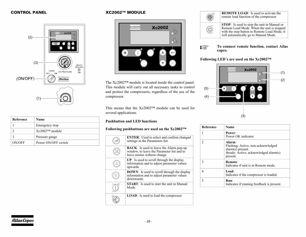
ing LED´s are used on the Xc2002™
REMOTE LOAD: Is used to activate the remote load function of the compressor
STOP: Is used to stop the unit in Manual or Remote Load Mode. When the unit is stopped with the stop button in Remote Load Mode, it will automatically go to Manual Mode.
To connect remote function, contact Atlascopco.
ence Name
Power:Power OK indicator.
Alarm:Flashing: Active, non-acknowledged alarm(s) present.Steady: Active, acknowledged alarm(s) present.
Remote:Indicates if unit is in Remote mode.
Load:Indicates if the compressor is loaded.
Run:Indicates if running feedback is present.
- 28 -
CONTROL PANEL XC2002™ MODULE
The Xc2002™ module is located inside the control panel.This module will carry out all necessary tasks to controland protect the compressors, regardless of the use of thecompressor.
This means that the Xc2002™ module can be used forseveral applications.
Pushbutton and LED functions
Following pushbuttons are used on the Xc2002™
Follow
Reference Name
1 Emergency stop
2 Xc2002™ module
3 Pressure gauge
ON/OFF Power ON/OFF switchENTER: Used to select and confirm changed settings in the Parameters list.
BACK: Is used to leave the Alarm pop-up window, to leave the Parameter list and to leave menus without changeUP: Is used to scroll through the display information and to adjust parameter values upwards.DOWN: Is used to scroll through the display information and to adjust parameter values downwards.START: Is used to start the unit in Manual Mode.
LOAD: Is used to load the compressor
Refer
1
2
3
4
5

- Regulating pressure
is view shows the regulating pressure and the runningurs.e also "Parameter list" on page 30 for selection betweentric (bar) or imperial (psi) units.
- Coolant temperature
is view shows the engine coolant temperature and thening hours.
e also "Parameter list" on page 30 for selection betweentric (°C) or imperial (°F) units.
- Oil pressure
is view shows the engine oil pressure and the runningurs.e also "Parameter list" on page 30 for selection betweentric (bar) or imperial (psi) units.
- Unit Type
is view shows the model type of the compressor. default unit type
is possible to scroll between configuration menu's byng the pushbuttons UP and DOWN.
RegP 0.37bar�00000.h
Temp 0°C�00000.h
Oil --bar�00000.h
Unit Type1 1 10
- 29 -
XC2002™ MENU OVERVIEWAt Xc2002™, the LCD will show the followinginformation through the display views:
1. in Normal condition (scroll through the information using UP and DOWN):
- Controller type & version
This view shows the controller type and the softwareversion number.
- Fuel level
This view shows the fuel level (in %) and the runninghours.
- Vessel pressure
This view shows the vessel pressure and the runninghours.See also "Parameter list" on page 30 for selection betweenmetric (bar) or imperial (psi) units
- Engine RPM
This view shows the engine running speed (in RPM) andthe running hours.
- Fuel pressure
This view shows the fuel pressure and the running hours.See also "Parameter list" on page 30 for selection betweenmetric (bar) or imperial (psi) units.
- Fuel consumption
This view shows the engine fuel consumption and therunning hours.See also "Parameter list" on page 30 for selection betweenmetric (L/h) or imperial (Gal/h) units.
- Alarm list- contains a list of active alarms
This view shows the number of active alarms and givesaccess to them. An overview is given in "Alarm Display (pop upwindow)" on page 33.
- Extra views display
This view shows the extra views available in thecontroller.
ThhoSeme
ThrunSeme
ThhoSeme
Th1 =It usi
Xc20021.40.0
Fuel 12%�00000.h
Vessel 2.1bar�00000.h
RPM 0�00000.h
E|C Fuel
pressure
�00000.h
--bar
E|C Fuel
rate
�00000.h
--L/h
Alarm list0 Alarm(s)
Extra Views

s shown on the Parameter list LCD:anguage
iew shows the language in use and with scroll UP orN a list of available languages and gives access to
is the default factory set language, however 6 otherges can be selected: English, French, Spanish,n, Italian, Chinese and Cyrillic (Russian). Allation in the Parameter List display is always inh.
uto Button
uto Button’ Parameter Needs to be set to active to the Auto/Remote Button/LED.Parameter is set to inactive (Default) then pressing
uto/Remote Button will NOT put the Xc2002 inRemote.
nit
enu can be accessed to select units of measure inmetric (°C, bar) or imperial (°F, psi) units.o "Parameter list" on page 30 for selection between (°C) or imperial (°F) units.
LanguageIcons
UnitC/bar C/bar F/psi
- 30 -
Pushing the ENTER button activates the configurationmenu which is shown on the display.
- Battery voltage
This view shows the battery voltage and the runninghours.
- Soot Load Indicator
Available in EXTRA VIEWS on control panelOnly visible when unit is operating. This screen has beenprovided for the operator to monitor the soot load of theDPF (read in percent of load)
- Compressor element temperature
This view shows the compressor element temperature andthe running hours.See also "Parameter list" on page 30 for selection betweenmetric (°C) or imperial (°F) units
- Air Inlet temperature
This view shows the air temperature at inlet and therunning hours.See also "Parameter list" on page 30 for selection betweenmetric (°C) or imperial (°F) units.
- Service Timer 1 & Service Timer 2
This view shows both Service Timers. The Service Timerindication is shown when service time has run out.The Service Timer indications counts upwards and givesan alarm when the set value is reached.
- LOG list
This view shows the alarm memory and gives access to it.
- Xc2002 Event LOG #01- Xc2002 Event LOG #02
This view shows the event log and the service timer.The event log will be stored upon shutdown or servicetimer acknowledgement.Emergency stop log will be stored separately
- Parameter list
This view shows a number of Parameter settings and givesaccess to them.The Parameter Menu's are pre-programmed!A password will be requested for when an attempt tochange a setting is about to be done (user password =2003)
Menu'- L
This vDOWthem.Icons languaGermainformEnglis
- A
The ‘AenableIf this the AAuto/
- U
This meither See alsmetric
Battery 24V00000.h
Elem.T 57°C�00000.h
E|C A. inlet
temperature
�00000.h
--°C
Service 1 500 h
Service 2 1000 h
LOG list
Xc 2002 EVENT LOG #01
New software dl
Time: 000000 h
Parameter

ATIONARY REGENERATION OCEDURE
las Copco recommends that the DPF configuration left in the AUTO mode at all times, however in theent that a stationary or manual regeneration insired the following process should be followed.Go to the "STATION REGEN" screen. For normaloperation this should be in OFF mode. Press the enter button, this function is passwordtected contact Atlas Copco service department. se the up or down arrow to change the selection to ON
d press the enter button. to the "DPF" screen. For normal operation this should
in the AUTO mode. ress the enter buttonse the up or down arrow to change the selection to ON
d press the enter button. his will set the unit up for regeneration, after a fewments the regeneration icon should appear confirming unit is regenerating. on completion of the stationary/forced regenerationis highly recommended to reset the unit to
tomatically regenerate to prevent engine derate &utdown due to high soot load. Follow the processlow to return the unit to AUTO mode for normaleration.Go to the "STATION REGEN" screen. (For normaloperation this should be in OFF mode). Press the enter button, this function is passwordtected contact Atlas Copco service department.se the up or down arrow to change the selection to OFF
d press the enter button. to the "DPF" screen. For normal operation this should
in the AUTO mode. ress the enter button, se the up or down arrow to change the selection toTO and press the enter button.he unit is now ready for normal operation.
- 31 -
- Auto NoLoad
When "no" selected the unit will remain in unload whennot loaded for a certain time.When "yes" selected the unit will switch to noload whenrunning unload for a certain time.
- ST1 Reset
- ST2 Reset
These views are the Service Timer resets. When "Yes" isselected a customer level password will be requested priorto approving the Service Timer Reset.When a service timer alarm occurs and is acknowledged,the service timer will be reset automatically.
- Diagnostic menu
This menu is used to power up the engine electronicswithout starting the engine. When this setting is switchedon, electric power will be supplied to the engineelectronics after half a minute delay. The unit can not bestarted as long as this parameter is swiched on.
See procedure for stationary forced / Regeneration prior toInitializing a Stationary Regeneration
- DPF - Diesel Particulate Filter
This view shows the DPF mode selected. When AUTO isselected the DPF will regenerate automatically. WhenOFF is selected, regeneration is disabled. When ON isselected manual regeneration is partially enabled (seeSTATION REGEN).
- Station Regen.
Stationary or manual DPF regeneration. This view showsthe stationary regeneration mode selected. When OFF isselected, manual regeneration is disabled. When ON isselected manual regeneration is enabled. The views DPFand STATION REGEN. must be set to ON for the unit toperform a stationary (manual) regeneration. DPF and STATION REGEN. are password protected.Note: Unit will not regenerate until soot level is ~72%
2. in Alarm condition (scroll through the information using UP and DOWN):- a list of all active Alarms
It is possible to scroll through the views, using the UP andDOWN buttons. The scrolling is continuous.If a special status comes up, the Status Display is shown.If an Alarm comes up, the Alarm Display is shown.
STPRAtbeevde–
§ pro§ UanGobe§ P§ Uan§ TmotheUpit aushbeop–
§ pro§ UanGobe§ P§ UAU§ T
Auto NoLoadNo No Yes
ST1 ResetNo No Yes

- 32 -
XC2002 – DPF INFORMATION - INDICATORS
Indicators Discription Operator Action
Exhaust Filter Cleaning Indicator Active when:
1. Exhaust gas temperature is high.
2. Elevated idle is active.
3. Exhaust filter cleaning is in process.
Machine can be operated as normal.If operating in an area where high exhaust temperature may be an issue, abort exhaust filter cleaning by using the disable feature. Only use disable feature in emergency situation.
Exhaust Filter Indicator Active when:Soot level in the exhaust filter indicates need for an exhaust filter cleaning.
Warning will be present on controller
Enable auto filter cleaning to allow a cleaning cycle.ORBegin a manual cleaning.
Exhaust Filter and Warning Indicators Active when:Machine performance is reduced due to moderately high soot level.
Warning will be present on controller
Begin a manual cleaning.
Exhaust Filter and Stop Indicators Active when:
Exhaust filter requires service, Machine performance is reduced due to Extremely High soot level and a stop engine request is made.
Service the exhaust filter.
Contact your servicing dealer.
Auto Cleaning Disabled Indicator Active when:Auto exhaust filter cleaning is disabled.
If possible, enable auto cleaning.
Always leave machine in auto cleaning mode unless forced to use a manual cleaning.Do not let machine idle excessively, exhaust filter performance is reduced.Read instruction manual before operating.
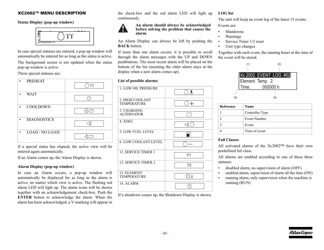
G liste unit will keep an event log of the latest 15 events.ents are:
ShutdownsWarningsService Timer 1/2 resetUnit type changes
gether with each event, the running hours at the time of event will be stored.
il Classesl activated alarms of the Xc2002™ have their owndefined fail class.
l alarms are enabled according to one of these threetuses:
disabled alarm, no supervision of alarm (OFF)enabled alarm, supervision of alarm all the time (ON)running alarm, only supervision when the machine is running (RUN)
eference Name
Controller Type
Event Number
Event
Time of event
Xc 2002 EVENT LOG #02
Element Temp. 2
Time: 000000 h
(1) (2)
(3) (4)
- 33 -
XC2002™ MENU DESCRIPTION
Status Display (pop-up window)
In case special statuses are entered, a pop-up window willautomatically be entered for as long as the status is active.The background screen is not updated when the statuspop-up window is active.These special statuses are:
If a special status has elapsed, the active view will beentered again automatically.If an Alarm comes up, the Alarm Display is shown.
Alarm Display (pop-up window)In case an Alarm occurs, a pop-up window willautomatically be displayed for as long as the alarm isactive, no matter which view is active. The flashing redalarm LED will light up. The alarm icons will be showntogether with an acknowledgement check-box. Push theENTER button to acknowledge the alarm. When thealarm has been acknowledged, a V-marking will appear in
the check-box and the red alarm LED will light upcontinuously.
An Alarm Display can always be left by pushing theBACK button.If more than one alarm occurs, it is possible to scrollthrough the alarm messages with the UP and DOWNpushbuttons. The most recent alarm will be placed on thebottom of the list (meaning the older alarm stays at thedisplay when a new alarm comes up).
List of possible alarms:
If a shutdown comes up, the Shutdown Display is shown.
LOThEv••••Tothe
FaAlpreAlsta•••
• PREHEAT
• WAIT
• COOLDOWN
• DIAGNOSTICS
• LOAD / NO LOAD
Fuel 12%�00000.h
An alarm should always be acknowledgedbefore solving the problem that causes thealarm.
1. LOW OIL PRESSURE
2. HIGH COOLANT TEMPERATURE
3. CHARGING ALTERNATOR
4. XDEC
5. LOW FUEL LEVEL
6. LOW COOLANT LEVEL
11. SERVICE TIMER 1
12. SERVICE TIMER 2
13. ELEMENT TEMPERATURE
14. ALARM
Y1
Y2
!
R
1
2
3
4

ER ON / OFF
on the battery switch. the machine on by switching the "ON/OFF" switch
position "ON".splay will show:
the scroll buttons (1) you can scroll through the information.
25.5V�00007.7 h
- 34 -
DURING OPERATION
Regularly carry out following checks:1. That the regulating valve (RV) is correctly adjusted, i.e.
starts decreasing the engine speed when reaching the preset working pressure in the receiver.
2. Check the air outlet temperature of the compressor element.
3. Check the engine oil pressure, the coolant tempera-ture and all lamps for normal readings.
4. Avoid the engine running out of fuel. Nevertheless, if this happens, fill the fuel tank and prime the fuel sys-tem to speed up starting (see section ).
OPERATIONS OVERVIEWIt is possible to control the compressor locally with theControl Box, remotely with the remote switch inputslocated on the back of the Control Box, or with softwarerunning on a PC with a CAN interface (PC Control Mode).The way one ends up in each status can differ from howthe Control Box is controlled, but the function of eachstatus stays the same.When reading this document, mind the difference betweena status and a procedure. A status is a state in the ControlBox's operation. A procedure is an action executed by theControl Box.Example: The Stopping procedure is executed in theStopping status, the Start Failure status and the Shutdownstatus.
POW
SwitchSwitchto the The di
With display
The doors must be closed during operationand may be opened for short periods only.
When the engine is running, the air outletvalves (ball valves) must always be put infully opened or fully closed position.

e remaining time is shown in the display:
anwhile the air receiver is depressurized.itch the "ON/OFF" switch to the position "OFF".
ait until the display is dark.itch the battery switch in the "OFF" position.
ERGENCY STOPe emergency stop button (2) is only to be used inergency situations; not for stopping procedures.
hen an emergency stop button is pressed, power to alltputs is terminated, by the emergency stop itselfrdware) as well as by the software.e display will show:
proceed operation the emergency stop button has to belocked and the alarm has to be acknowledged byssing the enter button (6).e display will show:
� � 25.5V00007.7 h
180 s
25.5V�00007.7 h
!
25.5V�00007.7 h
- 35 -
STARTINGPress the button "I" (4)• When the ambient temperature is below
10 °C (50 °F) the display will show:
Indicating that preheating is necessary before the engine will start.
• When the ambient temperature is over10 °C (50 °F) the display will show:
WARMING UPWhen the engine started the warming up is started. Thecompressor can be loaded after the compressor hasreached a temperature of 40 °C (104 °F), or after awarming up period of 5 minutes.After warming up the LED at the load button will blink atlow frequency, the engine will run idle.When pressing the load button (3) the display will show:
and the compressor will be loaded after warming up
LOADINGBy pressing the load button (3) the compressor will beloaded, the pressure will rise until it reaches the setting.The LED at the load button will blink at high frequencyand will be lit continuously when the set pressure isreached.The display will show:
With the scroll buttons (5) you can scroll through thedisplay information.STOPPING
To turn off the compressor first press the button "0" (1).The engine will run some time at minimum speed to cooldown and will stop finally.
Th
MeSwWSw
EMThemWou(haTh
TounpreTh
Fuel 12%�00000.h
25.5V�00007.7 h
22°C
25.5V�00007.7 h
28.9V�00007.7 h

rt
- 36 -
FAULT CODESThere are several parameters that are continuouslywatched.When one of these parameters exceeds its
specified limit the compressor will react depending thepresent status of the control box. The message displayedcan be a warning, a shut down or a start failure.
Display text Warning Shutdown Wait to staEngine Fault Codes (Canbus SAE J1939):Engine Sensor Failure X XFuel Pressure Low X XCoolant Temperature High X XInjector Failure X XOil Pressure low X XAir Inlet Temperature High XTurbo Boost Pressure High X XOil Temperature High XWater in Fuel X
Xc2002 Fault Codes:Sensor Failure (Fuel Level, Vessel Pressure, Regulating Pressure, Element Temperature)
X
Can SAE J1939 Communication Failure XOverspeed XFuel Level Low X XElement Temperature High X XCoolant Level Low XBattery Voltage Low XBattery Charge Failure XCheck Airfilters XStart Failure XStop Failure XService Timer 1 XService Timer 2 XEmergency Stop X

- 37 -
Maintenance
LIABILITY
The manufacturer does not accept any liability for anydamage arising from the use of non-original parts and formodifications, additions or conversions made without themanufacturer’s approval in writing.
SERVICE PAKS
A Service Pak is a collection of parts to be used for aspecific maintenance task, e.g. after 50, after 500 and after1000 running hours.It guarantees that all necessary parts are replaced at thesame time keeping down time to a minimum.The order number of the Service Paks are listed in theAtlas copco Parts List (ASL).
Use of service paksService Paks include all genuine parts needed for normalmaintenance of both compressor and engine.Service Paks minimize downtime and keep yourmaintenance budget low.Order Service Paks at your local Atlas copco dealer.
SERVICE KITS
A service kit is a collection of parts to fit a specific repairor rebuilding task.It guarantees that all necessary parts are replaced at thesame time which improves the uptime of the unit.The order numbers of the Service Kits are listed in theAtlas copco Parts List (ASL).
STORAGE
Run the compressor regularly, e.g. twice a week, untilwarm.Load and unload the compressor a few times to operate theunloading and regulating components. Close the air outletvalves after stopping.
Contact Atlas copco.
If the compressor is going to be storedwithout running from time to time,protective measures must be taken.
Unauthorised modifications can result ininjuries or machine damage.
Always keep the machine tidy to prevent firehazard.
Poor maintenance can void any warrantyclaims.

500 h 1000 hEvery 6 months Yearly1310 3004 47 1310 3004 48
efits of genuine parts, save on administration costs and
x x
x xx xx xx xx xx x
xx xx x
xxx
x x
- 38 -
PREVENTIVE MAINTENANCE
SCHEDULE
The schedule contains a summary of the maintenanceinstructions. Read the respective section before takingmaintenance measures.When servicing, replace all disengaged packings, e.g.gaskets, O-rings, washers.
For engine maintenance & Exhaust filters refer to EngineOperation Manual.The maintenance schedule has to beseen as a guideline for compressors operating in a dustyenvironment typical to compressor applications.Maintenance schedule can be adapted depending onapplication, environment and quality of maintenance.
MAINTENANCE SCHEDULE
To determine the maintenance intervals, use service hours, or calendar time, whichever occurs first.Service hours Initially at 50 hCalendarial Daily Supplied with unitService partsFor the most important subassemblies, Atlas copco has developed service kits that combine all wear parts. These service kits offer you the benare offered at reduced price, compared to the loose components. Refer to the parts list for more information on the contents of the service kits.Check engine oil level xCheck compressor oil level xCheck coolant level xDrain water from fuel filter xEmpty Air filter vaccuator valve xCheck electrolyte level and terminals of battery xCheck tyre pressure xCheck for leaks in air-, oil- or fuel system (2) xClean oil cooler (1)Clean radiator (1)Clean intercooler (1)Check torque of wheel nuts xCheck and adjust brake system (if installed) xTest safety valve (8)Grease door hingesGrease towing eye shaft or ball coupling and its shaftCheck rubber flexibles (2)Check shut down switchesReplace separator element (11)Check / adjust fan V-belts (3) (10) x(to be continued on page 39)

500 h 1000 hEvery 6 months Yearly
xx
x xxx xx xx xx xx x
xxevery 2000 hxxx
Keep the bolts of the housing, the liftingbeam, towbar and axles securelytightended. For torque values see sectionTechnical specifications.
See Engine operators manual forinformation regarding the dieselparticulate filters maintanance & service.
- 39 -
Notes:
Maintenance schedule(continuation of page 38)
Initially at 50 hDaily
Clean fuel tankReplace compressor oil (1) (12)Replace compressor oil filter (6) xAnalyse coolant (5) (9)Replace air filter element (1)Replace engine oil (3) (4)Replace engine oil filter (3)Replace primary fuel filter (7)Replace fuel prefilter (3) (7)Replace bleed off valve unloader Clean oil stop valveCheck and adjust engine inlet and outlet valves (3)Replace filter element from regulating valveClean flow restrictor in oil scavenge lineInspection by Atlas copco Service Technician
1. More frequently when operating in a dusty environment.2. Replace all rubber flexibles each 6 years, according to DIN 20066.3. Refer to the engine operation manual.4. 500 hours only valid when using PAROIL E mission Green.5. Check coolant every year. Change coolant every 5 years.6. Use Atlas copco oil filters, with by-pass valve, as specified in the parts list.7. Replace the fuel filters regularly. Gummed or clogged filters mean fuel starvation and reduced engine
performance. The quality of the fuel determines the frequency of renewal.8. See section Safety valve.9. The following part numbers can be ordered from Atlas copco to check on inhibitors and freezing point:• 2913 0028 00 refractometer• 2913 0029 00 pH meter.10. Replace V-belt after 3000 operating hours.11. Replace the element when the pressure drop exceeds 0.8 bar (11.6 psi).12. see section oil specification.

IL E Mission Green is a mineral based highmance diesel engine oil with a high viscosity- index.Copco PAROIL E Mission Green is designed toe a high level of performance and protection underrd' ambient conditions from -10°C (14°F) onward.IL E xtra and PAROIL E Mission Green are lowoil. These oils are to be used in Tier 4I / Stage IIIBs in order to provide the full performance and life of
gine and aftertreatment systems.
- 40 -
OIL SPECIFICATIONS
High-quality, mineral, hydraulic or synthesizedhydrocarbon oil with rust and oxidation inhibitors anti-foam and anti-wear properties is recommended.The viscosity grade should correspond to the ambienttemperature and ISO 3448.
PAROIL from Atlas Copco is the ONLY oil tested andapproved for use in all engines built into Atlas Copcocompressors and generators.Extensive laboratory and field endurance tests on AtlasCopco equipment have proven PAROIL to match alllubrication demands in varied conditions. It meetsstringent quality control specifications to ensure yourequipment will run smoothly and reliably.The quality lubricant additives in PAROIL allow forextended oil change intervals without any loss inperformance or longevity.PAROIL provides wear protection under extremeconditions. Powerful oxidation resistance, high chemicalstability and rust- inhibiting additives help reducecorrosion, even within engines left idle for extendedperiods.PAROIL contains high quality anti-oxidants to controldeposits, sludge and contaminants that tend to build upunder very high temperatures. PAROIL's detergentadditives keep sludge forming particles in a finesuspension, instead of allowing them to clog your filterand accumulate in the valve/rocker cover area.PAROIL releases excess heat efficiently, whilstmaintaining excellent bore-polish protection to limit oilconsumption.
PAROIL has an excellent Total Base Number (TBN)retention and more alkalinity to control acid formation.PAROIL prevents Soot build-up.PAROIL is optimized for the latest low emission EURO -3 & -2, EPA TIER II & III engines running on low sulphurdiesel for lower oil and fuel consumption.PAROIL E xtra is a Synthetic ultra high performancediesel engine oil with a high viscosity- index. Atlas CopcoPAROIL E xtra is designed to provide excellentlubrication from start-up at temperatures as low as -25°C(-13°F).
PAROperforAtlas provid'standaPAROSAPS enginethe en
It is strongly recommended to use AtlasCopco branded lubrication oils for bothcompressor and engine.
Only use synthetic compressor oil.
Never mix synthetic with mineral oil.Remark:When changing from mineral to synthetic oil(or the other way around), you will need to doan extra rinse:After a complete change over to synthetic oil,run the unit for a few minutes to allow properand complete circulation of the synthetic oil.Then drain the synthetic oil again and fill againwith new synthetic oil. To set correct oil levels,follow the normal instructions.

US gal Order number1.3 1630 0160 005.3 1630 0161 00
55.2 1630 0162 00264 1630 0163 00
US gal Order number1.3 1615 5947 005.3 1615 5948 0055.2 1615 5949 00
- 41 -
COMPRESSOR OIL
Choose your compressor oil based on the ambienttemperatures in the actual operating area.
Synthetic compressor oil PAROIL S
Mineral compressor oil PAROIL M
Litercan 5can 20
barrel 210container 1000
Litercan 5can 20
barrel 210
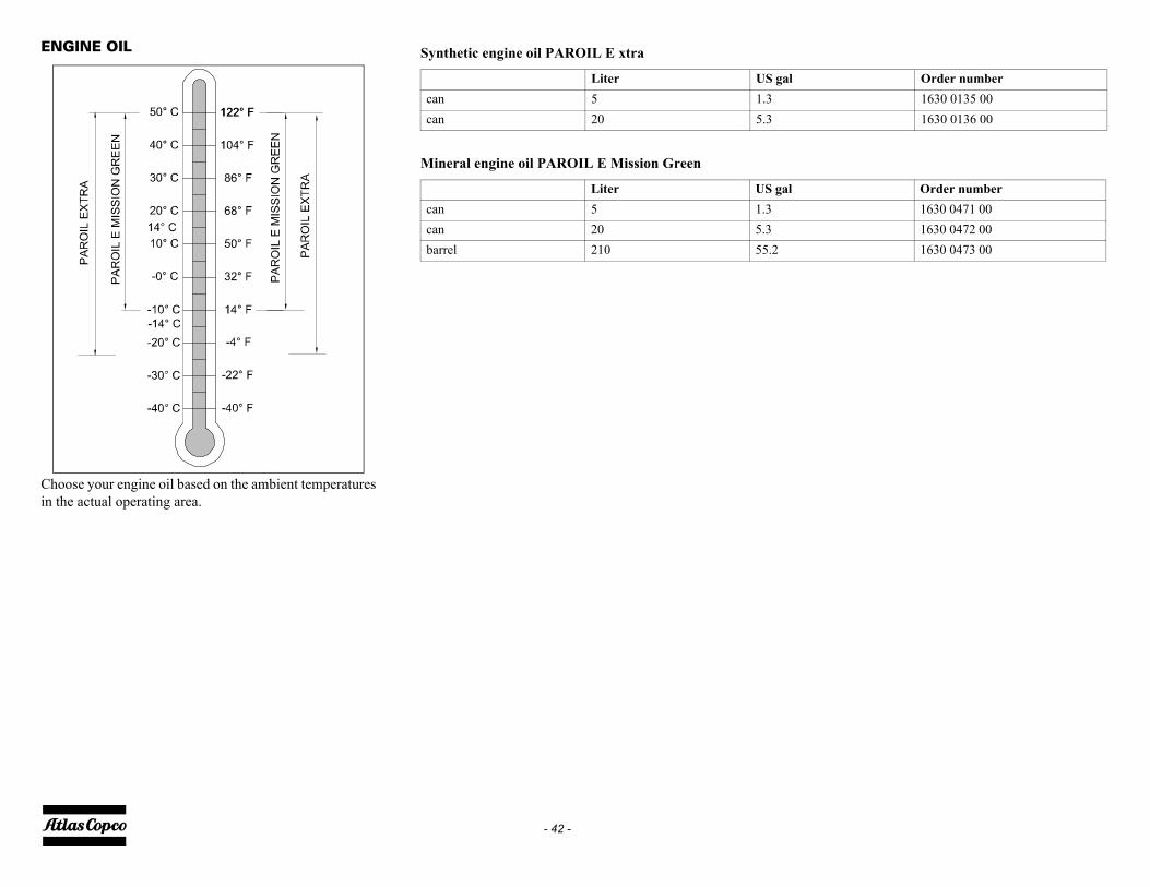
l Order number1630 0135 001630 0136 00
l Order number1630 0471 001630 0472 001630 0473 00
- 42 -
ENGINE OIL
Choose your engine oil based on the ambient temperaturesin the actual operating area.
Synthetic engine oil PAROIL E xtra
Mineral engine oil PAROIL E Mission Green
Liter US gacan 5 1.3can 20 5.3
Liter US gacan 5 1.3can 20 5.3barrel 210 55.2

ESEL FUEL RECOMMENDATIONS
Ultra Low Sulfur Diesel (ULSD) fuel 0.0015percent (15 ppm (mg/kg)) sulfur is requiredby regulation for use in engines certified byregulation for use in engines certified tononroad Tier 4 standards (U.S. EPA Tier 4certified) and that are equipped with exhaustaftertreatment systems.European ULSD 0.0010 percent (10ppm(mg/kg)) sulfur fuel is required by regulationfor use in engines certified to Europeannonroad Stage IIIB and newer standards andare equipped with exhaust aftertreatmentsystems.
- 43 -
OIL LEVEL CHECK
CHECK ENGINE OIL LEVELAlso consult the Engine Operation Manual for the oilspecifications, viscosity recommendations and oil changeintervals.For intervals, see Preventive maintenance schedule.Check engine oil level in accordance with the instructionsin the Engine Operation Manual and if necessary, top upwith oil.
CHECK COMPRESSOR OIL LEVEL
With the compressor standing horizontal, check the levelof the compressor oil.The pointer of the oil level gauge (1) must register in theupper extremity of the green range. Add oil if necessary.
DI
Before removing the oil filler plug (2), ensurethat the pressure is released by opening an airoutlet valve (3).

ING UP THE COMPRESSOR OIL
p the compressor. Wait a few minutes until the ssure is released through the automatic blow-down e. Make sure that all pressure is released by
sening the filler plug (1) one turn.ait a few minutes until the oil level is constant.emove the filler plug (1) and top up with oil until e pointer of the oil level gauge (2) is in the upper rt of the green area.
einstall and tighten the filler plug (1).
- 44 -
Misfueling with fuels of higher sulfur level can have thefollowing negative effects:• Shorten the time interval between aftertreatment
device service intervals (cause the need for more fre-quent service intervals).
• Adversely impact the performance and life of after-treatment devices (cause loss of performance).
• Reduce regeneration intervals of aftertreatment devices.
• Reduce engine efficiency and durability.• Increase the wear.• Increase the corrosion.• Increase the deposits.• Lower fuel economy.• Shorten the time period between oil drain intervals
(more frequent oil drain intervals).• Increase overall operating costs.• Failures that result from the use of improper fuels
will not be covered by warranty.•
OIL AND OIL FILTER CHANGE
ENGINE OIL AND OIL FILTER CHANGE
1. Run engine approximately 5 minutes to warm up oil. Shut engine off.
2. Remove oil pan drain plug (2).3. Drain crankcase oil from engine while warm.4. Turn filter element (1) using a suitable filter wrench to
remove. Discard oil filter element.5. Apply clean engine oil to the new filter at the inner (4)
and outer (3) seals and to filter threads.6. Wipe both sealing surfaces of the header with a clean
rag. Ensure notches in dust seal are properly installed in the slots in the housing. Replace dust seal if damaged.
7. Install and tighten oil filter by hand until firmly against dust seal . DO NOT apply an extra 3/4 to 11/ 4 turn after gasket contact as done with standard filters.
8. Tighten drain plug to specifications.
TOPP
1. Stoprevalvloo
2. W3. R
thpa
4. R

- 45 -
COMPRESSOR OIL AND OIL FILTER CHANGE
The quality and the temperature of the oil determine the oilchange interval.The prescribed interval is based on normal operatingconditions and an oil temperature of up to 100 °C (212 °F)(see section Preventive maintenance schedule).When operating in high ambient temperatures, in verydusty or high humidity conditions, it is recommended tochange the oil more frequently.
1. Run the compressor until warm. Close the outlet valve(s) (3) and stop the compressor. Wait until the pressure is released through the automatic blow-down valve. Unscrew the oil filler plug (2) by a single turn. This uncovers a vent hole, which permits any pressure in the system to escape.
2. Drain the compressor oil by removing all relevant drain plugs (4). Catch the oil in a drain pan. Unscrew the filler plug (2) to speed up draining. After drain-ing, reposition and tighten the drain plugs (4).
3. Remove the oil filters (1), e.g. by means of a special tool. Catch the oil in a drain pan.
4. Clean the filter seat on the manifold, taking care that no dirt drops into the system. Oil the gasket of the new filter element. Screw it into place until the gas-ket contacts its seat, then tighten one half turn only.
5. Fill the air receiver until the pointer of the oil level gauge is in the upper part of the green area. Be sure that no dirt gets into the system. Reinstall and tighten the filler plug.
6. Start the compressor and let it run unloaded for a few minutes.
7. Stop the compressor, wait a few minutes and top up with oil until the pointer of the oil level gauge is in the upper part of the green area.
In this case, contact Atlas Copco.
Never add more oil. Overfilling results in oilconsumption.

terval, draining is sufficient
PAROIL S xtreme
drainingdraining *
Vessel cover contaminated
clean
Vessel contaminated
clean
- 46 -
COMPRESSOR OIL FLUSHING
PROCEDURE
To avoid problems when changing over to a new type ofoil (see table) a special Compressor Oil FlushingProcedure has to be followed. The table is only valid whenthe replaced oil has not exceeded its lifetime. For moreinformation consult Atlas Copco Service dept.Aged oil can be recognized best by using an oil samplinganalysis program. Indicators for aged oil are strong smell,or contamination such as sludge and varnish inside the oilvessel and oil stop valve or a brownish colour of the oil.Whenever aged oil is discovered, eg. when changing theoil separator, contact Atlas Copco Service dept. to haveyour compressor cleaned and flushed.1. First thoroughly drain the system when the oil is warm,
leaving as little oil in the system as possible, especially in dead areas, if possible blow out remaining oil by pressurising the oil system. Check the instruction manual for detailed description.
2. Remove the compressor oil filter(s).3. Open the oil vessel and remove the oil separator ele-
ment.
4. Check the interior of the oil vessel (see pictures). If varnish deposits are discovered, contact Atlas Copco Service dept. and do not continue.
5. Put in a new oil separator, screw on new compressor oil filter(s) and close the oil vessel according to the instructions.
6. Fill the oil vessel with the minimum amount of replacement oil, run the compressor under light load conditions for 30 minutes.
7. Thoroughly drain the system when the oil is warm, leaving as little oil in the system as possible, espe-cially in dead areas, if possible blow out remaining oil by pressurising the oil.
8. Fill the system with the final oil charge.9. Run the compressor under light load conditions for
15 minutes and check for leakage. 10. Check the oil level and top up if necessary.11. Collect all waste lubricant used during the flushing
process and dispose of it in accordance with the applicable procedures for managing waste lubricant.
Not respecting compressor oil changingintervals in accordance with the maintenanceschedule, can lead to serious problems,including fire hazard! The manufacturer doesnot accept any liability for damage arisingfrom not following the maintenance scheduleor not using genuine parts.
Instructions on replacing the oil separatorelement are available from Atlas CopcoService dept.
•When changing over to the same oil within the oil changing in
PAROIL S
PAROIL S draining *PAROIL S xtreme draining
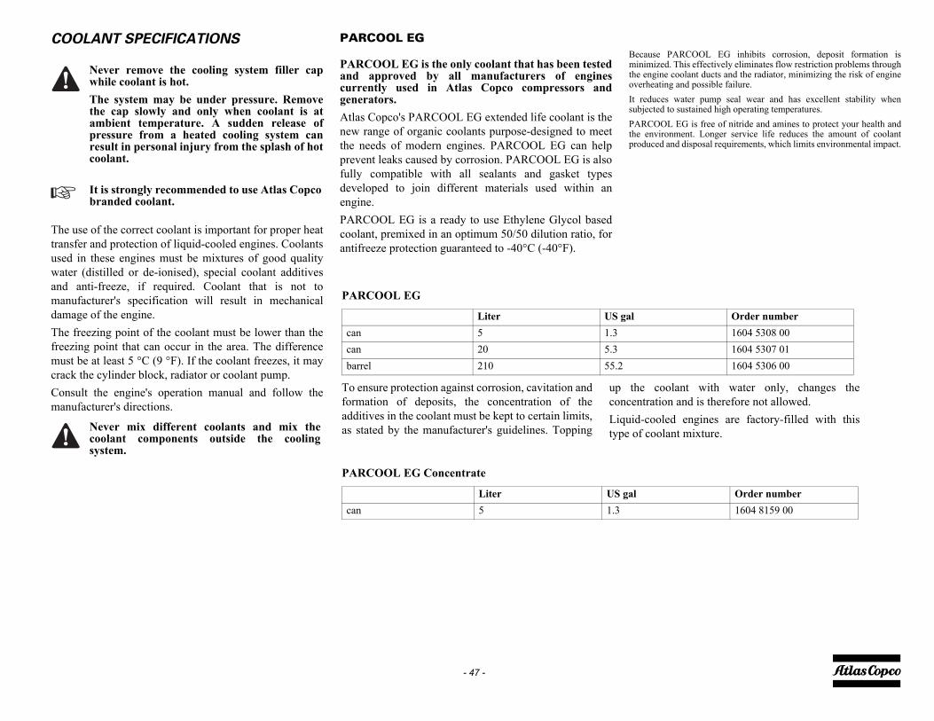
ause PARCOOL EG inhibits corrosion, deposit formation isimized. This effectively eliminates flow restriction problems through
engine coolant ducts and the radiator, minimizing the risk of enginerheating and possible failure.
reduces water pump seal wear and has excellent stability whenjected to sustained high operating temperatures.RCOOL EG is free of nitride and amines to protect your health and environment. Longer service life reduces the amount of coolantduced and disposal requirements, which limits environmental impact.
e coolant with water only, changes thetration and is therefore not allowed.-cooled engines are factory-filled with this coolant mixture.
Order number1604 5308 001604 5307 011604 5306 00
Order number1604 8159 00
- 47 -
COOLANT SPECIFICATIONS
The use of the correct coolant is important for proper heattransfer and protection of liquid-cooled engines. Coolantsused in these engines must be mixtures of good qualitywater (distilled or de-ionised), special coolant additivesand anti-freeze, if required. Coolant that is not tomanufacturer's specification will result in mechanicaldamage of the engine.The freezing point of the coolant must be lower than thefreezing point that can occur in the area. The differencemust be at least 5 °C (9 °F). If the coolant freezes, it maycrack the cylinder block, radiator or coolant pump.Consult the engine's operation manual and follow themanufacturer's directions.
PARCOOL EG
PARCOOL EG is the only coolant that has been testedand approved by all manufacturers of enginescurrently used in Atlas Copco compressors andgenerators.Atlas Copco's PARCOOL EG extended life coolant is thenew range of organic coolants purpose-designed to meetthe needs of modern engines. PARCOOL EG can helpprevent leaks caused by corrosion. PARCOOL EG is alsofully compatible with all sealants and gasket typesdeveloped to join different materials used within anengine.PARCOOL EG is a ready to use Ethylene Glycol basedcoolant, premixed in an optimum 50/50 dilution ratio, forantifreeze protection guaranteed to -40°C (-40°F).
BecmintheoveIt subPAthepro
Never remove the cooling system filler capwhile coolant is hot.The system may be under pressure. Removethe cap slowly and only when coolant is atambient temperature. A sudden release ofpressure from a heated cooling system canresult in personal injury from the splash of hotcoolant.
It is strongly recommended to use Atlas Copcobranded coolant.
Never mix different coolants and mix thecoolant components outside the coolingsystem.
PARCOOL EG
To ensure protection against corrosion, cavitation andformation of deposits, the concentration of theadditives in the coolant must be kept to certain limits,as stated by the manufacturer's guidelines. Topping
up thconcenLiquidtype of
PARCOOL EG Concentrate
Liter US galcan 5 1.3can 20 5.3barrel 210 55.2
Liter US galcan 5 1.3

l concentration measurement optimise the unique engine protection features of
e PARCOOL EG, the concentration of the Glycol in e water should always be above 33 vol.%.ixtures exceeding a 68 vol.% mix ratio in water are t recommended, as this will lead to high engine erating temperatures.
refractometer can be ordered from Atlas Copco ith part number 2913 0028 00.
PING UP/REPLACING COOLANTerify whether the engine cooling system is in a od condition (no leaks, clean,...).
heck the condition of the coolant. the condition of the coolant is no longer up to stan-rd, the complete coolant should be replaced (see ction Replacing the coolant).lways top-up with PARCOOL EG Concentrate / RCOOL EG.pping up the coolant with water only, changes the ncentration of additives and is therefore not lowed.
In case of a mix of different coolant productsthis type of measuring might provideincorrect values.
- 48 -
HANDLING PARCOOL EGPARCOOL EG should be stored at ambient temperatures,while periods of exposure to temperatures above 35 °C (95°F) should be minimized. PARCOOL EG can be stored fora minimum of 5 years in unopened containers without anyeffect on the product quality of performance.PARCOOL EG is compatible with most other coolantsbased on ethylene glycol, but you only get the benefits of5 years protection when its used on its own. Exclusive useof PARCOOL EG is recommended for optimum corrosionprotection and sludge control.For simple density-measuring of Ethylene Glycol andPropylene Glycol in general the standard available‘density’ measuring devices are used to measure theconcentration of EG. In case a device is used to measureEG, no PG can be measured afterwards as a result of thedifference in the density. More specific measurements canbe done by the use of a refractometer. This device canmeasure both EG and PG. A mix of both products will beshow unreliable results!Mixed EG coolants with identical glycol type can bemeasured by use of a refractometer as well as the ‘density’system. The mixed coolants will be considered as oneproduct.The use of distilled water is recommended. If you haveexceptionally soft water it would be acceptable, as well.Basically, the engine metals are going to corrode to someextent no matter what water you use, and hard water willencourage the resulting metal salts to precipitate.PARCOOL EG comes as a pre-mixed coolant to safeguardthe quality of the complete product.It is recommended that topping up of the cooling system isalways done with PARCOOL EG.
COOLANT CHECK
In order to guarantee the lifetime and quality of theproduct, thus optimising engine protection, regularcoolant-condition-analysis is recommended.The quality of the product can be determined by threeparameters:
Visual check• Verify the appearance of the coolant with regard to
its colour and make sure that no loose particles are floating around.
pH measurement• Check the pH value of the coolant using a pH-mea-
suring device.• The pH-meter can be ordered from Atlas Copco with
part number 2913 0029 00.• Typical value for EG = 8.6.• If the pH-level is below 7 or above 9.5, the coolant
should be replaced.
Glyco• To
thth
• Mnoop
• Aw
TOP• V
go• C• If
dase
• APA
• Tocoal
Never remove the cooling system filler capwhile coolant is hot.The system may be under pressure. Removethe cap slowly and only when coolant is atambient temperature. A sudden release ofpressure from a heated cooling system canresult in personal injury from the splash of hotcoolant.

low level, this quantity is to bethe cooling system.
-20° C (33%) -22° C -25° C -30° C -36° C
rate
- 49 -
TOPPING UP WITHOUT DRAINING FROM THE COOLING SYSTEMThe quantity of PARCOOL EG Concentrate to be topped up can be estimated with the following formula and/or graph:
Corrections concentrate in measured system towards 50% volume by using PARCOOL EG Concentrate
14
33
33 17 14 50 4,850- = =* /
40,0
0,5
1,0
1,5
2,0
2,5
3,0
3,5
4,0
4,5
5,0
5,5
6,0
5 6 7 8 9 10 11 12 13 14 15 16
1
2
3
4
5
Example:
Total volume coolant =
Measured concentration =
In case of expansion tank at filled without draining from
1. Refractometer indication2. Refractometer indication3. Refractometer indication4. Refractometer indication5. Refractometer indication
LiterVol %
Engine coolant capacity (liter)
Top-up volume PARCOOL EG Concentrate without drainage
Top
-up
volu
me
(lite
r)
PN: 1604 8159 00
Liter PARCOOL EG Concent

stimated with the following formula and/or graph:
rate
level, this quantity is to be cooling system.
0° C (33%)2° C5° C0° C6° C
- 50 -
TOPPING UP AFTER LIMITED QUANTITY DRAINING FROM THE COOLING SYSTEMThe quantity of PARCOOL EG Concentrate to be topped up after draining a calculated volume from the cooling system, can be e
Corrections concentrate in measured system towards 50% volume by using PARCOOL EG Concentrate
80
33
33
33
17
67
80 67 2050-
100-
= =* /
=
Example:
Total volume coolant =
Measured concentration =LiterVol %
PN: 1604 8159 00
4 8 12 16 20 24 28 32 36 40 44 48 52 56 60 64 68 72 76 80 840,0
2,5
5,0
7,5
10,0
12,5
15,0
17,5
20,0
22,5
25,0
1
2
3
4
5
Engine coolant capacity (liter)
Top-up volume PARCOOL EG Concentrate with drainage
Liter PARCOOL EG Concent
In case of expansion tank at lowfilled without draining from the
1. Refractometer indication -22. Refractometer indication -23. Refractometer indication -24. Refractometer indication -35. Refractometer indication -3
Top
-up
volu
me
(lite
r)

TTERY CARE
the battery is still dry, it must be activated as describedsection Activating a dry-charged battery.e battery must be in operation within 2 months froming activated; if not, it needs to be recharged first.
ECTROLYTE
ctrolyte in batteries is a sulphuric acid solution intilled water.e solution must be made up before being introducedo the battery.
TIVATING A DRY-CHARGED BATTERYTake out the battery.Battery and electrolyte must be at equal temperature above 10 °C (50 °F).Remove cover and/or plug from each cell.Fill each cell with electrolyte until the level reaches the mark on the battery. If there is no mark on the battery, the level must be above the plates for at least 10 mm (0.4 in) to 15 mm (0.6 in).Rock the battery a few times so that possible air bub-bles can escape; wait 10 minutes and check the level in each cell once more; if required, add electrolyte.Refit plugs and/or cover.Place the battery in the compressor.
Before handling batteries, read the relevantsafety precautions and act accordingly.
Read the safety instructions carefully.
Always pour the sulphuric acid carefullyinto the distilled water; never pour thewater into the acid.
- 51 -
REPLACING THE COOLANT
Drain• Completely drain the entire cooling system.• Used coolant must be disposed or recycled in accor-
dance with laws and local regulations.
Flush• Flush twice with clean water. Used coolant must be
disposed or recycled in accordance with laws and local regulations.
• It is recommended to let the unit drain overnight.• It should be clearly understood that the risk for con-
tamination is reduced in case of proper cleaning.• In case a certain content of ‘other’ coolant remains in
the system, the coolant with the lowest properties influences the quality of the ‘mixed’ coolant.
Fill• To assure proper operation and the release of trapped
air, run the engine until normal engine operation tem-perature is reached. Turn off the engine and allow to cool.
• From the Atlas copco Instruction book, determine the amount of PARCOOL EG required.
• Mix concentrate and water before filling.• Fill with a maximum rate of 10 l/min (0.35 cu.ft/
min).• Recheck coolant level and add coolant mixture if
necessary.
CLEANING COOLERS
Keep the Air Cooler (1), radiator (2) & Oil Coler (3) cleanto maintain the cooling efficiency.
Clean by air jet in the direction of the arrow.
Steam cleaning in combination with a cleansing agent maybe applied (do not use jet at max. power).
Close the service door(s).
BA
If in Thbe
EL
EledisThint
AC••
••
•
••
Caution: do not top off when the engine ishot.
Remove any dirt from the coolers with afibre brush. Never use a wire brush or metalobjects.
To avoid damaging the coolers, anglebetween jet and coolers should be approx.90 °.
Protect the electrical and controllingequipment, air filters, etc. againstpenetration of moisture.Never leave spilled liquids such as fuel, oil,coolant and cleansing agents in or aroundthe compressor.

- 52 -
RECHARGING A BATTERYBefore and after charging a battery, always check theelectrolyte level in each cell; if required, top up withdistilled water only. When charging batteries, each cellmust be open, i.e. plugs and/or cover removed.
Apply with preference the slow charging method andadjust the charge current according to the following rule ofthumb:Battery capacity in Ah divided by 20 gives safe chargingcurrent in Amp.
MAKE-UP DISTILLED WATERThe amount of water evaporating from batteries is largelydependant on the operating conditions, i.e. temperatures,number of starts, running time between start and stop,etc...If a battery starts to need excessive make-up water, thispoints to overcharging. Most common causes are hightemperatures or a too high voltage regulator setting. If a battery does not need any make-up water at all over aconsiderable time of operation, an undercharged batterycondition may be caused by poor cable connections or atoo low voltage regulator setting.
PERIODIC BATTERY SERVICE• Keep the battery clean and dry.• Keep the electrolyte level at 10 to 15 mm above theplates or at the indicated level; top up with distilled wateronly. Never overfill, as this will cause poor performanceand excessive corrosion.• Record the quantity of distilled water added.• Keep the terminals and clamps tight, clean, and lightelycovered in petroleum jelly.• Carry out periodic condition tests. Test intervals of 1 to3 months, depending on climate and operating conditions,are recommended.
• If doubtful conditions are noticed or malfunctions arise,keep in mind that the cause may be in the electical system,e.g.loose terminals, voltage regulator maladjusted, poorperformance of compressor, etc...
COMPRESSOR ELEMENT OVERHAULWhen a compressor element is due for overhaul, it needsto be done by Atlas copco. This guarantees the use ofgenuine parts and correct tools with care and precision.
Use a commercial automatic batterycharger according to its manufacturer’sinstructions.

- 53 -
Adjustments and servicing procedures
ADJUSTMENT OF THE CONTINUOUS
PNEUMATIC REGULATING SYSTEM
- 54 -
The working pressure is determined by the tension of thespring in the regulating valve (RV). This tension can beincreased to raise the pressure and decreased to lower it byturning the adjusting wheel clockwise and anti-clockwiserespectively.To adjust the normal working pressure, proceed asfollows:1. Loosen the lock nut of the regulating valve.2. Release Regulating Valve (turn out).3. With the outlet valves (AOV) closed, adjust the regu-
lating valve (RV), until a pressure is reached of nom-inal pressure + 1.5 to 2 bar (22 to 29 psi).
4. Lock the regulating valve (RV) by fixing the lock nut.

xt carefully examine the element for possible damage.ver beat or knock the element as this will damage it andre will be a danger of damage to the engine.refully clean the inside of the housing and put thement in the housing (see section Replacing the air filterment).
PLACING THE AIR FILTER ELEMENT
w elements must also be inspected for tears ornctures before installation.scard the element (4) when damaged.dirty safety cartridge (3) is an indication of a mal-ctioning air filter element. Replace the element and theety cartridge in this case.e safety cartridge cannot be cleaned.
Release the snap clips (1) and remove the dust trap (2). Clean the trap.
Remove the element (4) and the safety cartridge.Reassemble in reverse order of dismantling. Make sure the vacuator valve (6) points down.Inspect and tighten all air intake connections.
- 55 -
AIR FILTER ENGINE/COMPRESSOR
SERVICINGAlways select the service point according to the vacuumindicator or display message. A regular inspection orcleaning as it is sometimes practiced in the field is morelikely to be damaging than useful as there is a risk that theelement will be damaged and dust will gain access to theengine.
Atlas copco always recommends exchanging ratherthan cleaning the filter element in order to avoiddamage and ensure maximum engine protection.
MAIN PARTS
CLEANING THE DUST TRAPRemove dust daily.To remove dust from the dust trap pinch the vacuatorvalve (6) several times.
CLEANING INSTRUCTIONS FILTER ELEMENTIf element cleaning can not be avoided, care should betaken that the filter element (4) is not washed out. Pleasenote that engine damage can cause considerable costs,which makes the cost of a new filter element seeminsignificant.Safety cartridges (3) can not be cleaned but must beexchanged.Please note that a cleaned element will never match theservice life and performance of a new element.Take the element from the air filter housing (5) (seesection Replacing the air filter element).In order to clean, position a pipe with an end bent byapprox. 90° on the end of a compressed-air pistol. Thepipe must be long enough to reach the bottom of the filterelement. Carefully blow out the filter element with drycompressed air (max. 5 bar (72.5 psi)) from the inside tothe outside until there is no more development of dust. Theend of the pipe must not touch the element.
NeNetheCaeleele
RE
NepuDiA funsafTh
1.
2.3.
4.
The Atlas copco air filters are speciallydesigned for the application. The use of non-genuine air filters may lead to severedamage of engine and/or compressorelement.Never run the compressor without air filterelement.
1. Snap clips 4. Filter element2. Dust trap cover 5. Filter housing3. Safety cartridge (option) 6. Vacuator valve

- 56 -
AIR RECEIVER
The air receiver (1) is tested according to officialstandards. Regularly have inspections carried out inconformity with local regulations.
SAFETY VALVE
Following checks must be carried out on the safety valve(2):• A check of the opening of the lifting gear, twice a
year.This can be done by screwing the cap of the valve anti-clockwise.
• A check of the set pressure once a year according to the local regulations. This check cannot be done on the compressor and must be carried out on a proper test bench.
Daily drain condensate.
All adjustments or repairs are to be done byan authorized representative of the valvesupplier, see section Specific safetyprecautions.

HAUST FILTER / DIESEL PARTICULATE LTER ASH HANDLING AND DISPOSAL
HAUST FILTER DISPOSAL
Under federal, state, and/or local laws orregulations, Diesel Particulate Filter ashmay be classified as a hazardous waste.Hazardous wastes must be disposed of inaccordance with all applicable federal, stateand local laws or regulations governinghazardous waste disposal. Only a qualifiedservice provider should remove ash from theDPF. Personal protective equipment andclothing, maintained in a sanitary andreliable condition, should be used whenhandling and cleaning a DPF. See your JohnDeere dealer or qualified service providerfor assistance.
Proper management of an Exhaust Filterthat has reached the end of its useful life isrequired, since the ash or catalyst materialin the device may be classified as hazardouswaste under federal, state, and/orlocal lawsor regulations. Used Exhaust Filters,whichinclude the Diesel Particulate Filter,may beexchanged at any Engine manufacturer’sdealeror qualified service provider.
See Engine operator’s manual for furtherinformation regarding the Exhaust Filter.
- 57 -
EXHAUST FILTER
1. Diesel Particulate Filter (DPF)2. Diesel Oxidation Catalyst (DOC)
EXHAUST FILTER SYSTEM
An exhaust filter consisting of a diesel oxidation catalyst(DOC) and a diesel particulate filter (DPF) specifically tomeet the demands of offhighway applications. The DOCreduces carbon monoxide, hydrocarbons, and someparticulate matter. The downstream DPF traps and holdsparticulates remaining in the exhaust stream. Trappedparticles are eventually oxidized within the DPF through aprocess known as regeneration or exhaust filter cleaning.Under normal machine operation and with the system inAUTO mode, the exhaust filter system requires minimaloperator interaction.To avoid unnecessary buildup of diesel particulates or sootin the exhaust filter system;1. Utilize the Automatic (AUTO) Exhaust Filter Cleaning
mode.2. Avoid unnecessary idling.3. Use Atlas copco “PAROIL E mission Green Low
SAPS” engine oil.
4. Use only ultra low sulfur fuel.In addition to soot, ash deposits will also slowly build upin the DPF and cannot be removed through the engineexhaust filter cleaning process.When the exhaust filter has run several thousand hours,these ash deposits can restrict engine performance due toincreased back pressure.
DIESEL PARTICULATE FILTER MAINTENANCE AND SERVICEThe Exhaust Filter includes the Diesel Oxidation Catalyst(DOC) and Diesel Particulate Filter (DPF). The DPF isdesigned to retain residual ash, which is a noncombustibleresult of additives used in crankcase lubrication oils andthe fuel. The DPF provides many hours of maintenancefree operation. At some point the DPF will requireprofessional service to remove the accumulated ash. Theexact number of hours of operation before service isrequired will vary depending upon the engine’s powercategory, duty cycle and operating conditions, engine oilash content, and fuel quality.The exhaust filter’s dash lamp indicator or the dignosticcodes will indicate when the DPF needs ash removalservice.The removal of DPF ash must be done by removing theDPF from the machine and placing it into specializedequipment. Do not remove ash by using water or otherchemicals. Removing ash by these methods may damagethe material securing the DPF in its canister, resulting inthe loosening of the DPF element in the canister andsubjecting it to damage from vibration.
EXFI
EX
To correct this situation, replace theexhaust filter or have the exhaust filtercleaned in specialized equipment.
Do not power wash the filter assembly whenexternal skin temperature of assemblyexceeds 50° C (120° F).

itted with a see-through bowl, drain as needed based
equipped, half turn to one turn.
ed by bleeding all air from the fuel system.
of properly.
- 58 -
FUEL SYSTEM
PRIMING INSTRUCTIONS
Prime the fuel system in order to fill the fuel filter. Primethe fuel system in order to purge trapped air. The fuelsystem should be primed under the following conditions:• Compressor is put in operation for the first time• Running out of fuel• Storage• Replacement of the fuel filter
DRAINING INSTRUCTIONS
Fuel leaked or spilled onto hot surfaces orelectrical components can cause a fire. Tohelp prevent possible injury, turn the “ON/OFF” switch in position “OFF” whenchanging fuel filters or water separatorelements. Clean up fuel spills immediately.
Do not loosen the fuel lines at the fuelmanifold. The fittings may be damaged and/or a loss of priming pressure may occurwhen the fuel lines are loosened.
Diesel fuel quality & fuel suffer content mustcomply with all existing emissionsregulation for the area in which the unitoperates.
Do not use diesel fuel with suffer contentgreater than 1% (10,000 ppm).
Check the fuel filters (1) and (2) for water or debris. If filter is fon a daily visual inspection.1. Loosen drain plugs (3) at bottom of fuel filters or bowls, if 2. When fuel starts to drain out, tighten drain plugs securely.After draining water from the fuel filters, the filters must be prim
Drain water into a suitable container and dispose
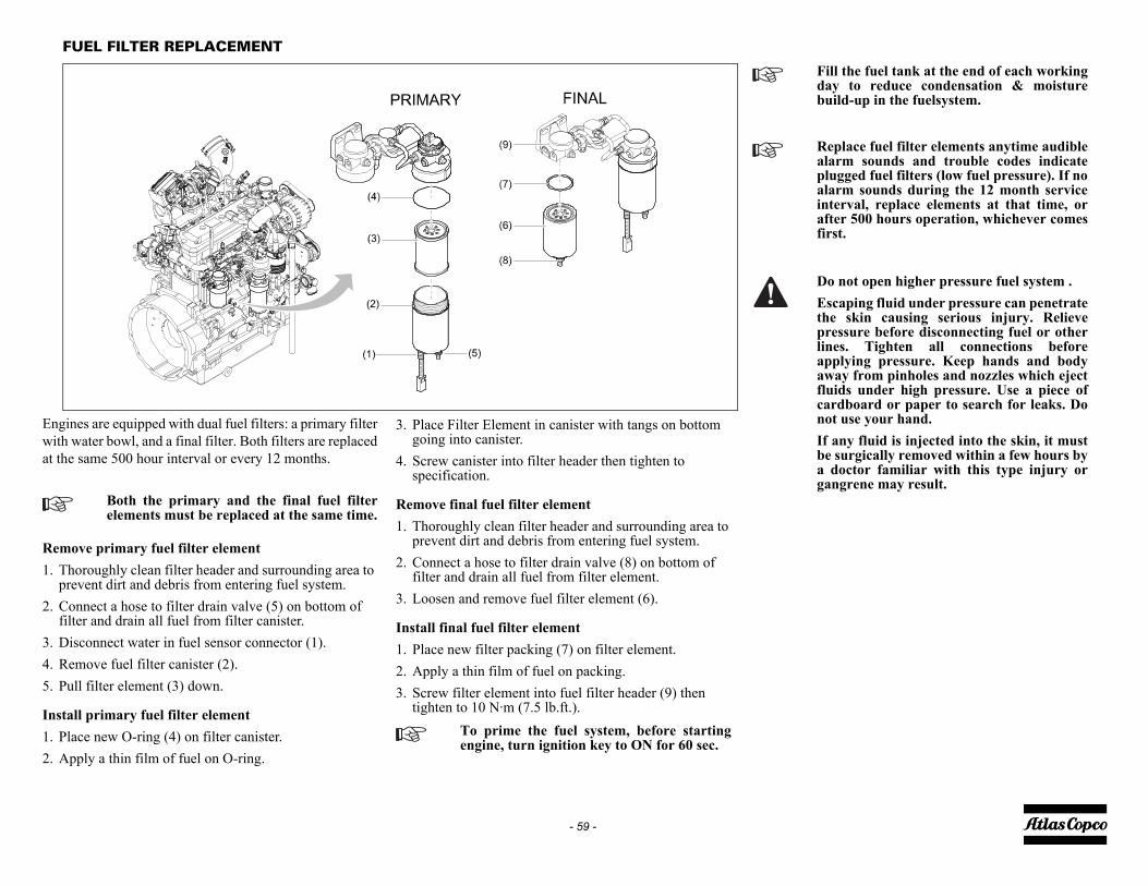
Fill the fuel tank at the end of each workingday to reduce condensation & moisturebuild-up in the fuelsystem.
Replace fuel filter elements anytime audiblealarm sounds and trouble codes indicateplugged fuel filters (low fuel pressure). If noalarm sounds during the 12 month serviceinterval, replace elements at that time, orafter 500 hours operation, whichever comesfirst.
Do not open higher pressure fuel system .Escaping fluid under pressure can penetratethe skin causing serious injury. Relievepressure before disconnecting fuel or otherlines. Tighten all connections beforeapplying pressure. Keep hands and bodyaway from pinholes and nozzles which ejectfluids under high pressure. Use a piece ofcardboard or paper to search for leaks. Donot use your hand.If any fluid is injected into the skin, it mustbe surgically removed within a few hours bya doctor familiar with this type injury organgrene may result.
- 59 -
FUEL FILTER REPLACEMENT
Engines are equipped with dual fuel filters: a primary filterwith water bowl, and a final filter. Both filters are replacedat the same 500 hour interval or every 12 months.
Remove primary fuel filter element1. Thoroughly clean filter header and surrounding area to
prevent dirt and debris from entering fuel system.2. Connect a hose to filter drain valve (5) on bottom of
filter and drain all fuel from filter canister.3. Disconnect water in fuel sensor connector (1).4. Remove fuel filter canister (2).5. Pull filter element (3) down.
Install primary fuel filter element1. Place new O-ring (4) on filter canister.2. Apply a thin film of fuel on O-ring.
Both the primary and the final fuel filterelements must be replaced at the same time.
3. Place Filter Element in canister with tangs on bottom going into canister.
4. Screw canister into filter header then tighten to specification.
Remove final fuel filter element1. Thoroughly clean filter header and surrounding area to
prevent dirt and debris from entering fuel system.2. Connect a hose to filter drain valve (8) on bottom of
filter and drain all fuel from filter element.3. Loosen and remove fuel filter element (6).
Install final fuel filter element1. Place new filter packing (7) on filter element.2. Apply a thin film of fuel on packing.3. Screw filter element into fuel filter header (9) then
tighten to 10 N·m (7.5 lb.ft.).To prime the fuel system, before startingengine, turn ignition key to ON for 60 sec.

- 60 -
BRAKE ADJUSTMENT
BRAKE SHOE ADJUSTMENT
Check the thickness of the brake lining.• Remove both black plastic plugs (3) one on each
wheel.• Check the thickness of the brake lining.
• After inspection and/or replacement re-insert both plugs (3).
Brake shoe adjustment re-establishes the brake lining-to-drum clearance and compensates for lining wear.
Before jacking up the compressor, connectit to a towing vehicle or attach a weight ofminimum 50 kg (110 lb) to the towbar.
When the brake lining has been worn to aminimum thickness, the brake shoes have tobe replaced (Min. thickness brake lining: 1mm (0.039 in)).
(1) (2)
(3)

amaged and that they are clamped tight to their
, etc., see .
sary.
as copco Service representative.
t hose leading to unloader. If air leaks from the hose, worn O-rings.
Service representative.
ssible: solve; else: contact Atlas copco.
llation.
as copco Service representative.
g hoses.
ssible: solve; else: contact Atlas copco.
- 61 -
Problem solving
It is assumed that the engine is in good condition and that there is adequate fuel flow tothe filter and injection equipment.
Problem: Compressor capacity or pressure below normal.
Make sure that the wires are not dterminals.For denomination of switches, relaysSee also section Control panel.
Problem: Pressure in air receiver rises above maximum and causes safety valve to blow.
An electrical fault must be traced by anelectrician.
Possible faults Corrective actions
Air consumption exceeds capacity of compressor. Check equipment connected.
Choked air filter elements (AF). Remove and inspect elements. Clean or replace, if neces
Regulating valve (RV) defective. Have regulating valve removed and inspected by an Atl
Blow down valve stuck in open position. Check and correct as necessary.
Loading valve (LV) leaking past O-ring. With compressor running at max. load speed, disconnecremove and inspect loading valve. Replace damaged or
Oil separator element clogged. Have element removed and inspected by an Atlas copco
Air intake throttle valve remains partially closed. Check unloader and identify reason for open valve; if po
Safety valve (SV) leaking. Remove and inspect. Replace if not airtight after reinsta
Blow-off valve leaking. Remove and inspect. Replace if necessary.
Possible faults Corrective actions
Regulating valve (RV) opens too late or its ball valve spring is broken. Have regulating valve removed and inspected by an Atl
Air leaks in regulating system. Check hoses and their fittings. Stop leaks; replace leakin
Air intake throttle valve does not close for some reason. Check unloader and identify reason for open valve; if po
Minimum pressure valve malfunctioning. Remove and inspect valve.
Blow-off valve malfunctioning. Remove and inspect valve.
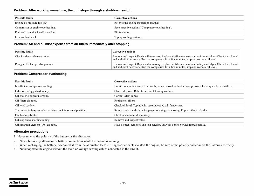
the polarity and connect the batteries correctly.
filter elements and safety cartridges. Check the oil level minutes, stop and recheck oil level.
filter elements and safety cartridges. Check the oil level minutes, stop and recheck oil level.
ith other compressors, leave space between them.
cessary.
sing. Replace if out of order.
pco Service representative.
- 62 -
Problem: After working some time, the unit stops through a shutdown switch.
Problem: Air and oil mist expelles from air filters immediately after stopping.
Problem: Compressor overheating.
Alternator precautions1. Never reverse the polarity of the battery or the alternator.2. Never break any alternator or battery connections while the engine is running.3. When recharging the battery, disconnect it from the alternator. Before using booster cables to start the engine, be sure of 4. Never operate the engine without the main or voltage sensing cables connected in the circuit.
Possible faults Corrective actions
Engine oil pressure too low. Refer to the engine instruction manual.
Compressor or engine overheating. See corrective actions “Compressor overheating”.
Fuel tank contains insufficient fuel. Fill fuel tank.
Low coolant level. Top up cooling system.
Possible faults Corrective actions
Check valve at element outlet. Remove and inspect. Replace if necessary. Replace airand add oil if necessary. Run the compressor for a few
Plunger of oil stop valve jammed. Remove and inspect. Replace if necessary. Replace airand add oil if necessary. Run the compressor for a few
Possible faults Corrective actions
Insufficient compressor cooling. Locate compressor away from walls; when banked w
Oil cooler clogged externally. Clean oil cooler. Refer to section Cleaning coolers.
Oil cooler clogged internally. Consult Atlas copco.
Oil filters clogged. Replace oil filters.
Oil level too low. Check oil level. Top up with recommended oil if ne
Thermostatic by-pass valve remains stuck in opened position. Remove valve and check for proper opening and clo
Fan blade(s) broken. Check and correct if necessary.
Oil stop valve malfunctioning. Remove and inspect valve.
Oil separator element (OS) clogged. Have element removed and inspected by an Atlas co

allows the unit to be put on and taken off the truck
cu.ft). Service and replacement of the filter can be
protect the environment and also enables units to be
ning oil from the engine sump due to overfilling or
iage, towbar and frame will be painted in black.
- 63 -
Available options
SupportA rigid support mounted version for rough construction conditions with the possibility to be mounted on a truck. The installationdaily. It is possible to handle the unit with a forklift.
Aftercooler + Water separatorThe aftercooler reduces the discharging air temperature to ambient + 10 °C (50 °F).On units with a cold weather option a bypass on the aftercooler is standard.
DD Filter (DD)Air filters that removes particles down to 1 micron and oil down to 0.1 ppm.
Fine Filter (PD)The fine-filter package completes the after cooler option. It removes particles and oil content down to 0.01 mg/m3 (3.5 oz/1000done without dismounting other parts or canopy.
Spark arrestorThe spark arrestor option prevents burning particles leaving the exhaust system. This reduces the fire hazard in dry conditions to operated in closed environments where there is a fire risk.
Inlet shutdownThe inlet shutdown provides protection to the diesel engine against over speeding caused by failure of the engine regulator, buraspiration of combustible fumes in hazardous environments. The inlet shutdown system is fully electronic.
Refinery packageThe refinery package is a combination of the Spark arrestor and Inlet shutdown options.
Customer colour canopy (1 colour)Special colour will apply on all external canopy parts or all internal parts visible from the outside, and wheel rims. The undercarr
Customer colour canopy (2 colours)Same to Customer colour (1) option, but with two (2) colours for which the customer will provide details.
Customer colour frame (1 colour)Customer colour for undercarriage, towbar and frame.
Coolant HeaterIn the block style coolant heater with an electrical cord attached

Torque value (Nm / lbf.ft)
270 (199.26)205 (151.29)205 (151.29)
46 (33.95)80 (59.04)205 (151.29)80 (59.04)
205 (151.29)46 (33.95)23 (16.97)
125 (92.25)205 (151.29)205 (151.29)205 (151.29)
es 12 (8.85)
tank cap of the fuel tank handtight.
- 64 -
Technical specifications
TORQUE VALUES
GENERAL TORQUE VALUESThe following tables list the recommended torques applied for general applicationsat assembly of the compressor.
For hexagon screws and nuts with strength grade 8.8
For hexagon screws and nuts with strength grade 12.9
CRITICAL TORQUE VALUES
Thread size Torque value (Nm / lbf.ft) M6 9 (6.64)M8 23 (16.97)M10 46 (34.69)M12 80 (59.04)M14 125 (92.25)M16 205 (151.29)
Thread size Torque value (Nm / lbf.ft) M6 15 (11.07)M8 39 (28.78)M10 78 (57.56)M12 135 (99.63)M14 210 (154.98)M16 345 (254.61)
AssembliesAxles to frame:Wheel nutsBolts, front axle/frameBolts, rear axle/frameCompressor to frame:Bolts, elements/gear casingBolts, elements/supportBolts, support/bufferBolts, buffer/frameEngine to frame:Bolts, engine/supportBolts, support/bufferBolts, buffer/frameLifting beams to frame:Bolts, lifting beams/yoke (M12)Bolts, lifting beams/yoke (M16)Bolts, lifting beams/A-FramesBolts, A-Frames/frameHose clamps:Pebra hose clamps on all IC/radiator hos
Secure the drain cock and

7 IT4 XAVS 400 JD7 IT4114.50206813.8100
7 IT4 XAVS 400 JD7 IT445815.522546.11115-1014-20-4
- 65 -
COMPRESSOR / ENGINE SPECIFICATIONS
REFERENCE CONDITIONS
The inlet conditions are specified at the air inlet grating outside the canopy.
LIMITATION
Designation XAS 400 JD7 IT4 XATS 400 JDAbsolute inlet pressure bar(e) 1 1
psi 14.7 14.7Relative air humidity % 0 0Air inlet temperature °C 20 20
°F 68 68Nominal effective working pressure bar(e) 6.9 10.34
psi 100 150
Designation XAS 400 JD7 IT4 XATS 400 JDMinimum effective receiver pressure bar(e) 4 4
psi 58 58Maximum effective receiver pressure, compressor unloaded
bar(e) 8.6 12psi 125 175
Maximum ambient temperature at sea level °C 51.67 51.67°F 125 125
Minimum starting temperature °C -10 -10°F 14 14
Minimum starting temperature, with coldstart equipment
°C -20 -20°F -4 -4
Altitude capability see curves

- 66 -
ALTITUDE UNIT PERFORMANCE CURVE
Max. allowable working pressure as a function altitude and ambient temperature.Limitations for start-up in terms of altitude are provided by the engine manufacturer.Limitations might differ in reality.

ATS 400 JD7 IT4 XAVS 400 JD7 IT400 240000 15000.2 188.33 399
5 < 5 0.005 < 0.005
A NAA NA.3 93.30 200
DB(A) 76 DB(A)
2 LW(A) 102 LW(A)
- 67 -
PERFORMANCE DATAAt reference conditions, if applicable, and at normal shaft speed, unless otherwise stated.
1) Free Air Delivery (volume flow rate) is measured according to ISO 1217 ed.3 1996 annex DTolerance:• +/- 5% 25 l/s (53 cfm) < FAD < 250 l/s (530 cfm)• +/- 4% 250 l/s (530 cfm) < FADThe international standard ISO 1217 corresponds to following national standards:• British BSI 1571 part 1• German DIN 1945 Part 1• Swedish SS-ISO 1217• American ANSI PTC9
Designation XAS 400 JD7 IT4 XEngine shaft speed, normal and maximum r/min 2400 24Engine shaft speed, compressor unloaded r/min 1500 15Free air delivery 1) without aftercooler l/s 191.6 19
cfm 406 40Typical oil content of compressed air mg/m3 < 5 <
oz/1000 cu.ft
< 0.005 <
Engine oil consumption (maximum) g/h NA Noz/h NA N
Compressed air temperature at outlet valve (without aftercooler) °C 93.3 93°F 200 20
Noise level- Sound pressure level (LP) complies with ISO 2151 under free field conditions at 7 m distance
dB(A) 76 DB(A) 76
- Sound power level (LW) complies with 2000/14/EC dB(A) 102 LW(A) 10
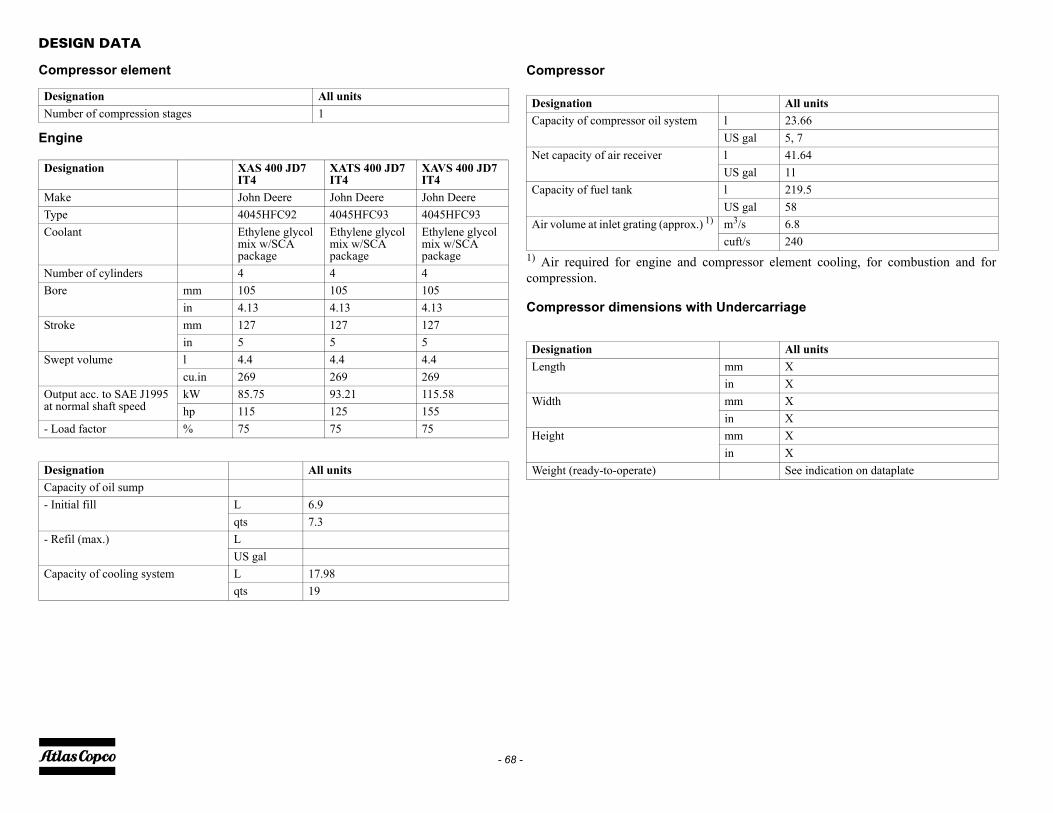
pressor element cooling, for combustion and for
ndercarriage
All unitsl 23.66US gal 5, 7l 41.64US gal 11l 219.5US gal 58m3/s 6.8cuft/s 240
All unitsmm Xin Xmm Xin Xmm Xin X
See indication on dataplate
- 68 -
DESIGN DATA
Compressor element
Engine
Designation All unitsNumber of compression stages 1
Designation XAS 400 JD7 IT4
XATS 400 JD7 IT4
XAVS 400 JD7 IT4
Make John Deere John Deere John DeereType 4045HFC92 4045HFC93 4045HFC93Coolant Ethylene glycol
mix w/SCA package
Ethylene glycol mix w/SCA package
Ethylene glycol mix w/SCA package
Number of cylinders 4 4 4Bore mm 105 105 105
in 4.13 4.13 4.13Stroke mm 127 127 127
in 5 5 5Swept volume l 4.4 4.4 4.4
cu.in 269 269 269Output acc. to SAE J1995 at normal shaft speed
kW 85.75 93.21 115.58hp 115 125 155
- Load factor % 75 75 75
Designation All unitsCapacity of oil sump- Initial fill L 6.9
qts 7.3- Refil (max.) L
US galCapacity of cooling system L 17.98
qts 19
Compressor
1) Air required for engine and comcompression.
Compressor dimensions with U
DesignationCapacity of compressor oil system
Net capacity of air receiver
Capacity of fuel tank
Air volume at inlet grating (approx.) 1)
DesignationLength
Width
Height
Weight (ready-to-operate)
SPOSAL OF MATERIALS
spose contaminated substances and material separately,ording to local applicable environmental legislations.fore dismantling a machine at the end of its operatingtime drain all fluids and dispose of according the
plicable local disposal regulations. move the batteries. Do not throw batteries into the fireplosion risk) or into the residual waste. Separate thechine into metal, electronics, wiring, hoses, insulation
d plastic parts. spose all components according to the applicableposal regulations.move spilled fluid mechanically; pick up the rest withsorbing agent (for example sand, sawdust) and disposeccording the applicable local disposal regulations. Do
t drain into the sewage system or surface water.
- 69 -
Disposal
GENERAL
When developing products and services, Atlas copco triesto understand, address, and minimize the negativeenvironmental effects that the products and services mayhave, when being manufactured, distributed, and used, aswell as at their disposal.Recycling and disposal policy are part of the developmentof all Atlas copco products. Atlas copco companystandards determine strict requirements.Selecting materials the substantial recyclability, thedisassembly possibilities and the separability of materialsand assemblies are considered as well as theenvironmental perils and dangers to health during therecycling and disposal of the unavoidable rates of notrecyclable materials.Your Atlas copco compressor consists for the most part ofmetallic materials, that can be remelted in steelworks andsmelting works and that is therefore almost infiniterecyclable. The plastic used is labelled; sorting andfractioning of the materials for recycling in the future isforseen.
DI
DiaccBelifeapRe(exmaanDidisReabit ano
This concept can only succeed with yourhelp. Support us by disposingprofessionally. By assuring a correctdisposal of the product you help to preventpossible negative consequences forenvironment and health, that can occurwith an inappropriate waste handling.Recycling and re-usage of material helps topreserve natural resources.

e By initials
- 70 -
Maintenance Log
Compressor Customer
Serial number
Service hours Maintenance action Dat

Date By initials
- 71 -
Maintenance Log
Compressor Customer
Serial number
Service hours Maintenance action

- 72 -


www.atlascopco.com