focs2-w/ca-e - prime climate€¦ · focs2_w_ca_e_1301_4802_201001_gb iii focs2-w/ca-e hfc r134a...
TRANSCRIPT

High effi ciencyAdaptability Silent operationHeat pump function
High effi ciency water-cooled chillers
FOCS2_W_CA_E_1301_4802_201001_GB
(The photo of the unit is indicative and may change depending on the model)
Climaveneta Technical Bulletin
1301 - 4802321 - 1299 kW
FOCS2-W/CA-E

IIFOCS2_W_CA_E_1301_4802_201001_GB
FOCS2-W/CA-E
HFC R134a
SUMMARY FOCS2-W/CA-E 1301 - 4802
Company quality system certi-fi ed to UNI EN ISO 9001
This company par-ticipates in the EuroventCertifi cation Programme.The products are listed in the Directory of certifi ed products.
Liability disclaimerThis bulletin is not exhaustive about: installation, use, safety precautions, handling and transport. Refer to the “General Manual of Installation” for further information.This bulletin refers to standard executions, particularly as re-gards dimensions, weight, electric, hydraulic, aeraulic and re-frigerant connections (where applicable). Contact Climaveneta Commercial Offi ce for further drawings and schemes.
Climaveneta declines any liability deriving from use of the bul-letin.This bulletin is the exclusive property of Climaveneta and all forms of copy are prohibited.The data contained herein are subject to change without no-tice.
Eurovent certifi cation ap-plied to units with cooling
capacity up to 1500 kW for air cooled water chillers and
water cooled liquid chillers.
1. Product presentation1.1 Energetic indices IPLV and ESEER1.2 High effi ciency1.3 Adaptability1.4 Silent operation1.5 Heat pump function
2. Unit description2.1 Standard unit composition 2.2 Certifi cations2.3 Unit’s test2.4 Electronic control W3000SE Large2.5 Versions2.6 Functions2.7 Accessories
3. Technical data 3.1 General technical data3.2 Cooling capacity performance3.3 Heat pump capacity performance3.4 Desuperheater capacity perfor.3.5 Recovery capacity performance
4. Operating range5. Hydraulic data
5.1 Water fl ow and pressure drop6. Electrical data7. Full load sound level8. Dimensional drawings9. Legend of pipe connections10.Condensation control devices11.Vpf system
pg. n° IIIpg. n° III pg. n° IIIpg. n° IIIpg. n° III pg. n° IIIpg. n° 1 pg. n° 1pg. n° 1pg. n° 2 pg. n° 2pg. n° 2 pg. n° 2pg. n° 3pg. n° 4pg. n° 4pg. n° 6pg. n° 10pg. n° 14pg. n° 16pg. n° 18pg. n° 19pg. n° 19pg. n° 21pg. n° 22pg. n° A1pg. n° A8pg. n° B1pg. n° C1

IIIFOCS2_W_CA_E_1301_4802_201001_GB
FOCS2-W/CA-E
HFC R134a
High effi ciency
1.1 Energetic indices IPLV and ESEERThe electrical power consumed by units is now being subjected to greater and greater attention. Indexes have been adopted that now take into consideration even use under partial load conditions, with external air fl ow lower than design project value and under partial load conditions in the chiller compres-sors installed.The valuation index adopted in the United States is called IPLV (Integrated Part Load Value) and is defi ned in the regulations issued by ARI (American Refrigeration Institute):
ARI Standard
(1) IPLV ARI
= (1*EER100%
+ 42*EER75%
+ 45*EER50%
+ 12*EER25%
) /100
where EER100%, EER75%, EER50%, EER25% are the ef-fi ciencies of the chiller in the various load conditions (100% - 75% - 50% and 25% respectively), calculated in the operating conditions shown below.
T of evaporator outlet water 6.7 °C constantEvaporator fouling factor 0.018 m2 °C/kWDelta T at full load 5°C Load 100% 75% 50% 25%Cond. water inlet temp 29.4°C 23.9°C 18.3°C 18,3°C Condenser fouling factor 0.044 m2 °C/kW
The multipliers 1, 42, 45 and 12 are the statistical coeffi cients allocated to the cooling effi ciencies calculated at the various load conditions analytically calculated by ARI for different ty-pologies of buildings and operating conditions in 29 different American cities.
In Europe, the ESEER index proposed by EECCAC (Energy Effi ciency and Certifi cation of Central Air Conditioners) is used in order to more closely interpret European air conditioning usage. ESEER (European Seasonal Energy Effi ciency Ratio) is defi ned as:
Proposal EECCAC
(3) ESEER = (3*EER100%
+ 33*EER75%
+ 41*EER50%
+ 23*EER25%
) /100
whereT of evaporator outlet water 7 °C constantDelta T at full load 5 °C Load 100% 75% 50% 25%Cond. water inlet temp. 30°C 26°C 22°C 18°C
These indices can be used to estimate the total energy require-ment of the plant during the summer season. Calculations using the ESEER index will therefore be more accurate than those using just the EER.
(1) IPLV (Integrated Part Load Value) ARI Standard indices
(2) EER (Energy Effi ciency Ratio) Effi ciency at full load (kW/kW)
5.60 6.27 6.65 6.64
5.60 6.27 6.65 6.66
5.59 6.06 6.46 6.47
5.61 6.11 6.64 6.47
5.59 6.07 6.59 6.52
5.59 6.08 6.62 6.58
5.60 6.26 6.85 7.00
5.59 6.07 6.78 7.02
5.61 6.12 7.00 7.25
5.59 6.07 688 7.19
5.59 6.08 6.89 7.20
1301 6.49
1401 6.50
1601 6.30
1801 6.40
2101 6.37
2401 6.40
2802 6.65
3202 6.57
3602 6.73
4202 6.65
4802 6.66
FOCS2-W/CA-E ESEER
EER values
100%30◦C
75% 26◦C
50% 22◦C
25%18◦C
(3) ESEER (European Seasonal Energy Effi ciency Ratio) Indices for EECCAC proposal
1.2 High effi ciencyThe version ́ CA-E´ is characterized by effi ciency beyond the ´Class A´ for Eurovent. The technological choices adopted assure the minimization of operating costs and therefore a quick payback time.
1.3 AdaptabilityAdaptability at the building’s cooling request thanks to the continuous capacity regulation, assured by sophisticated control’s logic.
1.4 Silent operationSilent operation thanks to the accurate unit’s design. Optional integral acoustic enclosure, further reduces the sound level beyond the best on market.
1.5 Heat pump functionHeat pump function water circuit side reversal.
1. PRODUCT PRESENTATION
1FOCS2_W_CA_E_1301_4802_201001_GB
FOCS2-W/CA-E
HFC R134a
Unit for indoor installation for chilled water production. Semiher-metic screw compressors optimized to operate with low com-pression ratio and R134a; shell and tubes condenser and direct expansion evaporator; electronic expansion valve. Frame in polyester-painted galvanized steel. High effi ciency unit: the in-novative optimized compressors and the high performing heat exchangers enhance EER values up to 5,6 at Eurovent stand-ars conditions.
Water cooled chillers The unit is supplied fully refrigerant charged and factory tested. On site installation only requires power and hydraulic connec-tion.
2.1 Standard unit composition Structure Frame in polyester-painted galvanized steel. The self-support-ing frame is built to guarantee maximum accessibility for servic-ing and maintenance operations.
Refrigerant circuit Unit with independent cooling circuits for each compressor as-suring continuous operation, limited pollution and ease of main-tenance. Each cooling circuit is fi tted standard with:- electronic adjustment valve- safety valves- high and low pressure transducers- compressor discharge check valve - on-off valve on the liquid and compressor delivery lines- liquid line solenoid valve- dryer fi lter with replaceable cartridge - refrigerant line sight glass with humidity indicator - high pressure switches.
Compressors Semi-hermetic screw compressors specifi cally designed for low temperature application.The compressor has 2 fi ve and six-lobe rotors: the fi ve-lobe rotor is splined directly onto the motor without any interposed overgears. The use of two rotors permits elevated volumetric output, uniform gas fl ow without jerks, reduced vibrations and dimensions. The bearings provided along the rotor axis, in a separate chamber isolated from the compression chamber, are in high-strenght carbon steel.Oil fl ow managed by pressure’s differences, without any dedi-cated oil pump, specifi cally designed so that the smallest dif-ferences between high pressure and suction pressure ensure suffi cient oil supply to the bearings, both at full and partial load. The built-in oil separator has 3 stages of separation with a 10 mm stainless steel mesh fi lter ensuring the constant presence of oil inside, with an oil carry over rate lower than 0,5%.Compressor’s continuous modulation thanks to a slide valve which, depending on the position assumed, permits the com-pression’s chamber stepless reduction. Each compressor par-tializes down to 25% of its maximum capacity.In addition to standard no-load switch-on procedure, the mo-tor is fi tted with electric devices limiting the absorbed current during start-up. Each compressor is fi tted with manual reset motor thermal protection, controls for the delivery gas tempera-ture and the oil level fl ow and an electric resistance to heat the carter while the compressor is stopped.
A check valve on the refrigerant outlet assures the compressor from the risk of reverse rotation after stopping. A compressor discharge valve is used to force the refrigerant into the heat exchangers during the compressors’ maintenance operation. Heat exchanger on plant side Direct expansion evaporator; refrigerant fl ows inside the tubes and water on the shell side. Baffl es in the shell increase turbo-lence and therefore enhance the heat exchange’s effi ciency. Steel shell insulated with a foamed closed-cell elastomer 10 mm thickness and 0.033 W/mK at 0°C thermal conductivity. In-ternal copper tubes are mechanically fi tted onto the plates and grooved internally to enhance the heat exchange between re-frigerant and water. A differential pressure switch is present as standard to control the waterfl ow while the unit is working pre-venting the ice formation. The heat exchanger complishes with PED and ASME regulation, respectively concerning the operat-ing pressures and stresses. Flexible joint water connection.
Heat exchanger on heat source side 2-steps shell and tube condenser, fl ooded type, with water fl ow-ing inside and refrigerant fl owing outside the pipes. Only for the units in function /H (heat pump reversible on hydraulic side), the steel shell is insulated with a foamed polyethylene closed-cell mat of 10 mm thickness and a thermal conductivity of 0.033 W/mK at 0°C to avoid condensation on its surface. The cop-per tubes are internally and externally grooved to improve heat exchange. Heads can be removed to inspect the tubes. Under request it’s possible to have a 4-steps heat exchanger (water side) for application with low-medium temperature sources (for example underground water). The heat exchanger complies with PED standards, concerning to operating pressure. Flexible joint water connection.
Electrical and control panel Electrical and control panel built to EN60204-1 and EC204-1 standards, complete with: - electronic controller - control circuit transformer - general door lock isolator - power circuit with bar distribution system - fuses for compressors - compressors protection with internal thermal overload - terminals for cumulative alarm block - remote on/off terminals - spring-type control circuit terminal board - phases sequence and minimum/maximum voltage control.
2.2 Certifi cations EUROVENT - certifi cation programme CE – Product quality certifi cate for the European Union GOST – Product quality certifi cate for Russian Federation SAFETY QUALITY LICENCE – Product quality certifi cate for Popular Republic of China M&I – Quality Certifi cation for Australia and New Zealand Machine Directive 2006/42/CE Pressure Equipment Directive PED 97/23/EC Low voltage Directive 2006/95/EC Electromagnetic compatibility Directive 2004/108/EC ISO 9001 - Company Quality Management System Certifi ca-tionISO 14001 - Company Environmental Management System Certifi cation
2. UNIT DESCRIPTION

2FOCS2_W_CA_E_1301_4802_201001_GB
FOCS2-W/CA-E
HFC R134a
2.3 Unit’s test Tests carried out along the all productive process as imposed by ISO9001. Possibility to have performance and acousti-cal witness tests, with the support of qualifi ed technical opera-tors. Performance tests give the possibility to measure electric data, waterfl ows, operating temperature, absorbed and given power, both at full load and partial load condition. It’s even pos-sible to have a simulation of the most common alarm states and the pressure drops (water side) measurements. The acoustical tests allow to verify level of sound emissions of the unit accord-ing to ISO3744.
2.4 Electronic control W3000SE Large The controller W3000 large offers the latest control and fun-ctions specially developed for these units. The keypad is generously sized with full operating status di-splay. The controls and detailed LCD make access to machine settings easy and safe. These resources permit to diirectly act on the unit settings through a multilevel menu, available in several languages. The diagnostics includes full management of alarms with black-box functions and alarm record for better analysis of unit performance. For multi-units plants a special device to coordi-nate and manage all the resources is available as an option; energy metering device is even possible as an option. Super-vision is easy through Climaveneta devices or with various options for interfacing to ModBus, Bacnet, Echelon LonTalk protocols. Compatibility with remote keyboard (management up to 10 units). Clock available with programming of operation (standard 4 days and 10 time bands). Temperature regulation features the continuous capacity modulation, based on a neutral zone and the return water temperature control. It´s even possible the steps regulation, based on the return water temperature, with proportional or proportional+integral logic. As option is possible to choose the VPF system control inte-grated on-board to the units.
2.5 Versions CA-E, very high effi ciency version, Class A enhanced Super high effi ciency unit for the minimum investment payback time. EER of 5.6 at standard condition. Electronic expansion valve, high performing heat exchangers and generous heat ex-change’s surfaces. 2-steps condensers water side.
2.6 Functions < >, standard unit Standard unit for production of chilled water
/D, with Desuperheater Unit for production of chilled water, complete of an auxiliary heat exchanger on the discharge section of the compressor to the superheat reclaim. The reclaim heat is approximately the 20% of the total cooling capacity. This function is used for ap-plication with domestic hot water production or other secondary uses, as support of the existing boiler.
/R, with total heat Reclaim Unit for the production of chilled water, with a dedicated heat exchanger refrigerant/water for the condensation heat reclaim. The heat reclaim is managed to reach the set-point. This func-tion is used for air treatment in applications with AHU or for domestic hot water production together with an auxiliary boiler.
/H, Hydraulic side reversible heat pump Heat pump reversible on hydraulic side. The unit has, as stand-ard, an additional temperature probe on condenser and an extra insulating material on it. The controller is set to manage the unit on a double set-point, depending on the commutation: summer or winter mode.

3FOCS2_W_CA_E_1301_4802_201001_GB
FOCS2-W/CA-E
HFC R134a
2.7 Accessories - Kit HWT
Kit for extending the operating limits of the unit: maximum condenser outlet temperature 65°C. To control the tempera-ture of the hot water produced, this accessory must be applied to the unit in function/H. The accessory is required for appli-cations at elevated condensation temperatures (heat pump, heat recovery at high temperatures or critical installations with dry-coolers).
- Integral acoustical enclosure basicEnclosure realized with peraluman panels lined with an acous-tic insulation made by polyester fi ber of thickness 30 mm. The sound power level reduction achieved with this accessory is 12 dB(A).
- Integral acoustical enclosure plusEnclosure realized with peraluman panels lined with a special acoustic insulation composed by 5 alternating layers of poly-urethane and gaiter of total thickness 50 mm. The sound pow-er level reduction achieved with this accessory is 16 dB(A).
- Partial heat reclaim management0-10 V signal to control the auxiliary pumps on the desuper-heat circuit. This option minimizes pumps’ consumption: they are called to work only when gas saturated discharge tem-perature is higher than the tank one. (Thermostat and pumps at client responsibility)
- Compressors’ on/off signalAuxiliary contactors to give a voltage free signal.
- Automatic circuit breakersOver-current switch on the major electrical loads.
- Demand limitDigital input (voltage free).
- Modbus connectivityTwo-directional communications board.
- Bacnet connectivityTwo-directional communications board.
- Echelon connectivityTwo-directional communications board.
- Auxiliary signal 4-20 mAAnalog input 4-20 mA.
- 0-10 V signal for the condensation’s control0-10 V signal on terminal board for the condensation con-trol. For dry-cooler or cooling tower applications, it permits to modulate the fans’ speed in order to maintain the condensing pressure in a pre-defi ned range. Max transmission length 30 m. Shielded cable is recommended.
- Relay for pump(s) managementRelay for the pump(s) on/off.
- CuNi condensersShell and tube heat exchanger recommended for applications with water with a high corrosion potential. Headers, shell, baffl es and refrigerant connection in carbon steel. Available tubes in CuNi 90/10 all, or CuNi 70/30; the last option is rec-ommended for marine water applications. [Consider a penali-zation on the condensation temperature of 2°C for 90/10 alloy, and of 3°C for 70/30]
- VPF system (see dedicate section)Predisposition for the variable fl ow pumps’ control on the pri-mary circuit. The system comprises: extensions on the con-troller to read the system’s pressure transducer signals (4-20 mA) and the consequent management of pumps and bypass valve (0-10 V signal), additional pressure transducer as extra safety device. (Pressure transducer, pumps and bypass valve at client responsibility)
- Pressostatic valve for the condensation control (see dedicate section)Pressostatic valve with grey cast iron body. It’s used for regu-lating the fl ow of water as a function of the condensing pres-sure, maintaining it constant during operation. When the re-frigeration plant is stopped, the cooling water fl ow is shut off automatically. The valve is selected and tested by Climavene-ta during the unit’s test. Recommended for applications with low temperature water, for example groundwater, where it’s request the condensation pressure’s control and it’s possible to work with variable fl ow on the rejection circuit (Separately supplied, not mounted)
- Soft startElectronic device adopted to manage the inrush current. This reduces the current peak when the motor starts. Starting takes place therefore without jerks and consequently reduces wear of the motor and allow the electrical system to be more favourably sized.
Other accessories- Flanged evaporator connectors - Flanged condenser connection - Evaporator fl owswitch (water side) - Compressor intake valve - Power factor correction - Rubber anti vibration device - Numbered wiring - Multi-units control devices (sequencer, Manager3000,
FWS3000). Separately supplied- Remote Keyboard predisposition - Remote signal for double set-point - Container packing.
SIZE 1301 1401 1601 1801 2101 2401 2802
CA-EFOCS2-W
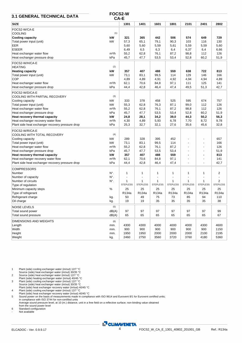
3.1 GENERAL TECHNICAL DATA
COOLING (1)
Cooling capacity kW 321 365 442 506 574 649 729Total power input (unit) kW 57,3 65,1 79,1 90,3 103 116 130EER ESEER
5,606,49
5,606,5
5,596,3
5,61 6,4
5,59 6,37
5,596,4
5,606,66
Heat exchanger water flow m³/h 55,2 62,8 76,1 87,2 98,8 112 126Heat exchanger pressure drop kPa 45,7 47,7 53,5 53,4 52,8 60,2 51,9
FOCS2-W/CA-E
FOCS2-W/H/CA-E HEATING (2)
Heating capacity kWTotal power input (unit) kWCOP Heat exchanger water flow m³/hHeat exchanger pressure drop kPa
35773,14,8962,144,4
40783,14,8970,642,8
48899,54,9184,846,4
559 114 4,92 97,1 47,4
638 129 4,94 111 49,5
7221464,9412551,3
8131664,8914142,7
FOCS2-W/D/CA-E COOLING WITH PARTIAL RECOVERY (3)
Cooling capacity kW 333 378 458 525 595 674 757Total power input (unit) kW 55,3 62,8 76,3 87,1 99,0 112 126Heat exchanger water flow m³/h 55,2 62,8 76,1 87,2 98,8 112 126Heat exchanger pressure drop kPa 45,7 47,7 53,5 53,4 52,8 60,2 51,9Heat recovery thermal capacity kW 24,8 28,1 34,2 39,0 44,3 50,2 56,3Heat exchanger recovery water flow m³/h 4,30 4,89 5,93 6,78 7,70 8,72 9,78Plant side heat exchanger recovery pressure drop kPa 25,3 32,7 32,1 27,6 35,6 45,6 32,8
FOCS2-W/R/CA-E COOLING WITH TOTAL RECOVERY (4)
Cooling capacity kWTotal power input (unit) Heat exchanger water flow Heat exchanger pressure drop Heat recovery thermal capacity
kWm³/hkPakW
289 328 395 452 - - 65773,1 83,1 99,5 114 - - 16655,2 62,8 76,1 87,2 - - 12645,7 47,7 53,5 53,4 - - 51,9357 407 488 559 - - 813
Plant side heat exchanger recovery pressure drop Heat exchanger recovery water flow
42,7-- 47,4 46,442,844,4kPa141-- 97,1 84,870,662,1m³/h
COMPRESSORS Number Number of capacity Number of circuits N°.
N°.N°. 1 1 1 1 1 1 2
- - - - - - -1 1 1 1 1 1 2
Type of regulation STEPLESS STEPLESS STEPLESS STEPLESS STEPLESSSTEPLESSSTEPLESS
383535 35 351919kg.Oil charge 1109485 73 754950kg.Refrigerant charge
R134aR134aR134a R134a R134aR134aR134aType of refrigerant % 25 25 25 25 25 25 25Minimum capacity steps
NOISE LEVELS (5)
Total sound power dB(A) 97 97 97 97 97 97 996765 656565dB(A)Total sound pressure 6565
DIMENSIONS AND WEIGHTS (6)
Length Width Height Weight
mm.mm.mm.kg.
4300900
19502460
4300900
19502750
4000900
20003560
4000 900
2000 3720
4000 900
2000 3760
4300900
21004180
4600115021955360
1 Plant (side) cooling exchanger water (in/out) 12/7 °C Source (side) heat exchanger water (in/out) 30/35 °C 2 Source (side) heat exchanger water (in/out) 12/7 °C Plant (side) heating exchanger water (in/out) 40/45 °C 3 Plant (side) cooling exchanger water (in/out) 12/7 °C Source (side) heat exchanger water (in/out) 30/35 °C Plant (side) heat exchanger recovery water (in/out) 40/45 °C 4 Plant (side) cooling exchanger water (in/out) 12/7 °C Plant (side) heat exchanger recovery water (in/out) 40/45 °C 5 Sound power on the basis of measurements made in compliance with ISO 9614 and Eurovent 8/1 for Eurovent certified units; in compliance with ISO 3744 for non-certified units Average sound pressure level, at 10 (m.) distance, unit in a free field on a reflective surface; non-binding value obtained from the sound power level 6 Standard configuration - Not available
4ELCADOC - Ver. 0.9.9.17 FOCS2_W_CA_E_1301_40802_201001_GB Ref.: R134a

SIZE 3202 3602 4202 4802 CA-E
FOCS2-WGENERAL TECHNICAL DATA
COOLING (1)
Cooling capacity kW 884 1012 1147 1299 Total power input (unit) kW 158 180 205 232 EER ESEER
5,596,57
5,616,73
5,596,64
5,59 6,66
Heat exchanger water flow m³/h 152 174 197 224 Heat exchanger pressure drop kPa 58,6 41,3 55,0 65,0
FOCS2-W/CA-E
FOCS2-W/H/CA-E HEATING (2)
Heating capacity kWTotal power input (unit) kWCOP Heat exchanger water flow m³/hHeat exchanger pressure drop kPa
9771994,9117046,4
11182274,9219447,5
12752584,9422149,5
1443 292 4,94 251 51,6
FOCS2-W/D/CA-E COOLING WITH PARTIAL RECOVERY (3)
Cooling capacity kW 917 1050 1190 1347 Total power input (unit) kW 153 174 198 224 Heat exchanger water flow m³/h 152 174 197 224 Heat exchanger pressure drop kPa 58,6 41,3 55,0 65,0 Heat recovery thermal capacity kW 68,3 77,9 88,6 100 Heat exchanger recovery water flow m³/h 11,9 13,5 15,4 17,4 Plant side heat exchanger recovery pressure drop kPa 32,1 27,5 35,6 45,6 FOCS2-W/R/CA-E COOLING WITH TOTAL RECOVERY (4)
Cooling capacity kWTotal power input (unit) Heat exchanger water flow Heat exchanger pressure drop Heat recovery thermal capacity
kWm³/hkPakW
790 904 - - 199 227 - - 152 174 - - 58,6 41,3 - - 977 1118 - -
Plant side heat exchanger recovery pressure drop Heat exchanger recovery water flow
- -47,546,4kPa- -194170m³/h
COMPRESSORS Number Number of capacity Number of circuits N°.
N°.N°. 2 2 2 2
- - - - 2 2 2 2
Type of regulation STEPLESS STEPLESS STEPLESS STEPLESS
70 707070kg.Oil charge 207 213144131kg.Refrigerant charge
R134a R134aR134aR134aType of refrigerant % 25 25 25 25 Minimum capacity steps
NOISE LEVELS (5)
Total sound power dB(A) 99 99 99 99 676767dB(A)Total sound pressure 67
DIMENSIONS AND WEIGHTS (6)
Length Width Height Weight
mm.mm.mm.kg.
4950115021956410
5220115021956870
4920115023507850
4920 1285 2430 8470
1 Plant (side) cooling exchanger water (in/out) 12/7 °C Source (side) heat exchanger water (in/out) 30/35 °C 2 Source (side) heat exchanger water (in/out) 12/7 °C Plant (side) heating exchanger water (in/out) 40/45 °C 3 Plant (side) cooling exchanger water (in/out) 12/7 °C Source (side) heat exchanger water (in/out) 30/35 °C Plant (side) heat exchanger recovery water (in/out) 40/45 °C 4 Plant (side) cooling exchanger water (in/out) 12/7 °C Plant (side) heat exchanger recovery water (in/out) 40/45 °C 5 Sound power on the basis of measurements made in compliance with ISO 9614 and Eurovent 8/1 for Eurovent certified units; in compliance with ISO 3744 for non-certified units Average sound pressure level, at 10 (m.) distance, unit in a free field on a reflective surface; non-binding value obtained from the sound power level 6 Standard configuration - Not available
5ELCADOC - Ver. 0.9.9.17 FOCS2_W_CA_E_1301_4802_201001_GB Ref.: R134a

CA-E3.2 COOLING CAPACITY PERFORMANCE
FOCS2-W
130130 32 35 40 42 25 25 30 32 35 40 42 25 30 32 35 40 42
6 7 8 Tev Pf Pat Qev Dpev
338 324 318 309 293 287 351 336 330 321 305 298 363 348 342 333 317 31044,7 50,5 53,1 57,1 64,6 67,8 44,8 50,6 53,2 57,3 64,8 68,0 44,9 50,8 53,3 57,4 65,0 68,258,2 55,7 54,7 53,1 50,5 49,4 60,4 57,8 56,8 55,2 52,5 51,4 62,6 60,0 58,9 57,3 54,5 53,450,8 46,5 44,9 42,4 38,3 36,7 54,7 50,2 48,4 45,7 41,3 39,6 58,8 54,0 52,1 49,2 44,6 42,7
Tcd
383 374 371 366 358 355 65,6 64,2 63,6 62,8 61,4 60,9
Pt Qcd Dpcd 49,5 47,4 46,5 45,3 43,4 42,7
395 387 383 378 370 36767,8 66,3 65,7 64,9 63,5 62,952,9 50,6 49,7 48,4 46,3 45,5
408 399 395 390 381 37870,1 68,5 67,9 67,0 65,5 64,956,4 53,9 53,0 51,6 49,3 48,5
Dpev 63,0 57,9 55,9 52,9 47,9 46,0 67,5 62,1 59,9 56,7 51,5 49,4 72,2 66,5 64,2 60,8 55,2 53,0Qev 64,8 62,1 61,1 59,4 56,5 55,4 67,1 64,3 63,2 61,5 58,6 57,4 69,4 66,6 65,4 63,7 60,7 59,4Pat 45,0 50,9 53,5 57,6 65,1 68,4 45,1 51,0 53,6 57,7 65,3 68,6 45,1 51,0 53,7 57,8 65,4 68,7Pf 376 361 354 345 328 321 389 373 367 357 340 333 403 386 380 369 352 345
9 10 11 Tev
Dpcd Qcd Pt 421 412 408 402 393 390
72,3 70,7 70,0 69,1 67,6 67,0 60,1 57,4 56,4 54,9 52,5 51,6
434 424 421 415 405 40274,6 72,9 72,2 71,2 69,6 69,063,9 61,1 60,0 58,4 55,8 54,8
448 437 433 427 417 41476,8 75,1 74,4 73,4 71,7 71,167,9 64,9 63,7 62,0 59,2 58,1
140130 32 35 40 42 25 25 30 32 35 40 42 25 30 32 35 40 42
6 7 8 Tev Pf Pat Qev Dpev
384 368 361 351 334 327 399 382 375 365 347 340 413 396 389 378 360 35350,9 57,4 60,3 64,9 73,4 77,1 51,0 57,6 60,5 65,1 73,6 77,3 51,1 57,7 60,6 65,3 73,8 77,566,2 63,4 62,2 60,5 57,5 56,2 68,7 65,8 64,6 62,8 59,7 58,5 71,2 68,2 67,0 65,2 62,0 60,753,0 48,6 46,8 44,2 39,9 38,3 57,1 52,4 50,5 47,7 43,1 41,3 61,3 56,3 54,3 51,4 46,5 44,6
Tcd
435 426 422 416 407 404 74,7 73,0 72,4 71,4 69,9 69,3
Pt Qcd Dpcd 47,8 45,7 44,9 43,7 41,8 41,1
450 440 436 430 420 41777,2 75,4 74,8 73,8 72,2 71,651,0 48,8 47,9 46,6 44,6 43,9
464 454 450 444 434 43079,7 77,9 77,2 76,2 74,5 73,854,4 52,0 51,1 49,7 47,6 46,7
Dpev 65,8 60,5 58,3 55,2 50,0 48,0 70,4 64,8 62,6 59,2 53,7 51,6 75,3 69,3 67,0 63,4 57,6 55,3Qev 73,7 70,7 69,4 67,5 64,3 63,0 76,3 73,2 71,9 70,0 66,6 65,3 78,9 75,7 74,4 72,4 69,0 67,6Pat 51,2 57,8 60,8 65,4 74,0 77,7 51,2 57,9 60,9 65,6 74,2 77,9 51,3 58,0 61,0 65,7 74,4 78,1Pf 428 410 403 392 373 366 443 425 417 406 387 379 458 439 432 420 400 392
9 10 11 Tev
Dpcd Qcd Pt 479 468 464 458 447 443
82,2 80,4 79,7 78,6 76,8 76,2 58,0 55,4 54,4 52,9 50,6 49,7
494 483 478 472 461 45784,8 82,9 82,1 81,0 79,2 78,561,6 58,9 57,8 56,3 53,8 52,8
509 497 493 486 475 47087,4 85,4 84,6 83,5 81,6 80,965,5 62,5 61,4 59,7 57,1 56,0
160130 32 35 40 42 25 25 30 32 35 40 42 25 30 32 35 40 42
6 7 8 Tev Pf Pat Qev Dpev
465 446 438 425 403 394 483 463 455 442 419 409 500 480 472 459 435 42562,3 70,1 73,4 78,8 88,4 92,6 62,6 70,3 73,7 79,1 88,8 92,9 62,8 70,6 74,0 79,3 89,1 93,380,1 76,8 75,4 73,2 69,4 67,8 83,1 79,7 78,3 76,1 72,1 70,5 86,1 82,7 81,2 79,0 74,9 73,259,3 54,5 52,6 49,6 44,5 42,5 63,9 58,8 56,7 53,5 48,1 46,0 68,6 63,3 61,0 57,7 51,9 49,6
Tcd
528 516 511 504 492 486 90,5 88,5 87,7 86,5 84,4 83,5
Pt Qcd Dpcd 52,8 50,6 49,7 48,3 45,9 44,9
545 533 528 521 508 50293,5 91,5 90,7 89,4 87,2 86,256,4 54,0 53,0 51,6 49,0 48,0
563 551 546 538 524 51996,6 94,5 93,7 92,3 90,0 89,160,2 57,6 56,6 55,0 52,3 51,2
Dpev 73,6 67,9 65,6 62,0 55,9 53,5 78,9 72,8 70,3 66,6 60,1 57,5 84,3 78,0 75,3 71,3 64,5 61,7Qev 89,2 85,7 84,2 81,9 77,8 76,0 92,3 88,7 87,2 84,8 80,6 78,8 95,5 91,8 90,2 87,8 83,5 81,7Pat 62,9 70,8 74,2 79,6 89,4 93,6 63,1 71,0 74,4 79,9 89,7 94,0 63,2 71,1 74,6 80,1 90,0 94,3Pf 518 498 489 475 451 441 536 515 506 492 468 458 554 533 524 510 485 474
9 10 11 Tev
Dpcd Qcd Pt 581 568 563 555 541 535
99,7 97,6 96,7 95,3 92,9 91,9 64,1 61,4 60,3 58,6 55,7 54,5
599 586 581 572 558 552103 101 99,7 98,3 95,8 94,868,2 65,3 64,1 62,3 59,2 57,9
617 604 598 590 575 568106 104 103 101 98,7 97,772,4 69,4 68,1 66,2 62,9 61,5
Pt [kW] - Heating capacity
Dpcd [kPa] - Source (side) heat exchanger pressure drop Qcd [m³/h] - Source (side) heating exchanger water flow
'-' Conditions outside the operating range Waterflow and pressure drop on heat exchangers calculated with 5°C of delta T
Tev [°C] - Plant (side) cooling exchanger output water temperaturePf [kW] - Cooling capacity Pat [kW] - Total power input Qev [m³/h] - Plant (side) heat exchanger water flow Dpev [kPa] - Plant (side) cooling exchanger pressure drop
Tcd [°C] - Source (side) heat exchanger output water temperature
6ELCADOC - Ver. 0.9.9.17 FOCS2_W_CA_E_1301_4802_201001_GB Ref.: R134a

CA-ECOOLING CAPACITY PERFORMANCE
FOCS2-W
180130 32 35 40 42 25 25 30 32 35 40 42 25 30 32 35 40 42
6 7 8 Tev Pf Pat Qev Dpev
533 511 502 487 462 451 553 531 521 506 480 469 573 550 541 525 499 48771,2 80,0 83,8 89,9 101 106 71,5 80,3 84,2 90,3 101 106 71,7 80,6 84,5 90,6 102 10791,8 88,0 86,4 83,9 79,5 77,7 95,2 91,4 89,7 87,2 82,7 80,8 98,7 94,8 93,1 90,5 85,9 83,959,2 54,4 52,5 49,5 44,4 42,4 63,7 58,7 56,6 53,4 48,0 45,9 68,5 63,1 60,9 57,5 51,8 49,5
Tcd
604 591 586 577 563 557 104 101 100 99,1 96,6 95,6
Pt Qcd Dpcd 53,9 51,6 50,7 49,3 46,9 45,9
625 611 605 597 582 575107 105 104 102 99,8 98,857,6 55,2 54,2 52,6 50,0 49,0
645 631 625 616 600 594111 108 107 106 103 10261,5 58,8 57,8 56,2 53,4 52,2
Dpev 73,5 67,8 65,5 61,9 55,8 53,4 78,7 72,7 70,2 66,4 60,0 57,4 84,2 77,8 75,2 71,2 64,4 61,6Qev 102 98,2 96,5 93,8 89,1 87,1 106 102 99,9 97,2 92,4 90,4 109 105 103 101 95,7 93,6Pat 71,9 80,8 84,7 90,9 102 107 72,0 81,1 85,0 91,2 103 107 72,2 81,3 85,2 91,5 103 108Pf 594 570 560 545 517 506 614 590 580 564 536 524 635 611 600 584 555 543
9 10 11 Tev
Dpcd Qcd Pt 666 651 645 636 620 613
114 112 111 109 106 105 65,5 62,7 61,6 59,8 56,8 55,6
686 671 665 656 639 632118 115 114 113 110 10969,6 66,7 65,5 63,6 60,5 59,2
707 692 685 676 658 651121 119 118 116 113 11274,0 70,9 69,6 67,6 64,2 62,9
210130 32 35 40 42 25 25 30 32 35 40 42 25 30 32 35 40 42
6 7 8 Tev Pf Pat Qev Dpev
605 579 568 552 525 514 627 601 590 574 545 534 650 623 612 595 566 55480,7 90,8 95,1 102 115 120 81,0 91,2 95,6 103 115 121 81,3 91,6 96,0 103 116 121104 99,6 97,8 95,1 90,3 88,4 108 103 102 98,8 93,9 91,9 112 107 105 103 97,5 95,558,6 53,7 51,8 48,9 44,2 42,3 63,1 57,9 55,9 52,8 47,7 45,7 67,8 62,3 60,1 56,8 51,4 49,3
Tcd
685 670 664 654 640 634 118 115 114 112 110 109
Pt Qcd Dpcd 55,6 53,2 52,2 50,8 48,5 47,7
708 692 686 676 661 654121 119 118 116 113 11259,5 56,8 55,8 54,3 51,8 50,9
732 715 708 698 682 676126 123 122 120 117 11663,5 60,7 59,5 57,9 55,3 54,2
Dpev 72,8 66,9 64,6 61,1 55,4 53,1 78,0 71,8 69,3 65,6 59,5 57,0 83,4 76,8 74,2 70,3 63,8 61,2Qev 116 111 109 106 101 99,0 120 115 113 110 105 103 124 119 117 114 109 106Pat 81,6 91,9 96,4 103 116 122 81,8 92,3 96,8 104 117 122 82,0 92,6 97,1 104 117 123Pf 673 646 634 617 587 575 697 669 657 639 609 596 721 692 680 661 630 617
9 10 11 Tev
Dpcd Qcd Pt 755 738 731 721 704 697
130 127 125 124 121 120 67,6 64,6 63,4 61,7 58,8 57,7
779 761 754 743 725 718134 131 129 128 125 12372,0 68,8 67,5 65,6 62,6 61,4
803 784 777 766 747 740138 135 133 132 128 12776,5 73,1 71,7 69,7 66,5 65,2
240130 32 35 40 42 25 25 30 32 35 40 42 25 30 32 35 40 42
6 7 8 Tev Pf Pat Qev Dpev
684 655 643 625 594 582 710 680 668 649 617 604 736 705 693 674 641 62891,3 103 108 116 130 136 91,7 103 108 116 130 137 92,1 104 109 117 131 137118 113 111 108 102 100 122 117 115 112 106 104 127 121 119 116 110 10866,8 61,3 59,1 55,8 50,4 48,3 72,0 66,1 63,7 60,2 54,5 52,2 77,4 71,1 68,6 64,9 58,7 56,3
Tcd
776 758 751 741 724 717 133 130 129 127 124 123
Pt Qcd Dpcd 57,7 55,1 54,1 52,7 50,3 49,4
802 783 776 766 748 741137 134 133 131 128 12761,6 58,9 57,8 56,3 53,7 52,7
828 809 802 790 772 765142 139 138 136 133 13165,8 62,8 61,7 60,0 57,3 56,2
Dpev 83,0 76,4 73,7 69,7 63,2 60,6 88,9 81,9 79,0 74,8 67,9 65,1 95,1 87,6 84,6 80,2 72,8 69,8Qev 131 126 124 120 114 112 136 130 128 125 119 116 140 135 133 129 123 120Pat 92,4 104 109 117 132 138 92,7 104 110 118 132 138 93,0 105 110 118 133 139Pf 762 731 718 698 665 651 789 756 743 723 689 675 815 782 769 748 713 699
9 10 11 Tev
Dpcd Qcd Pt 854 835 827 816 796 789
147 143 142 140 137 135 70,1 67,0 65,7 63,9 61,0 59,8
881 861 853 841 821 813151 148 146 144 141 14074,6 71,2 69,9 68,0 64,8 63,6
908 887 879 866 846 837156 152 151 149 145 14479,2 75,7 74,3 72,2 68,8 67,5
Pt [kW] - Heating capacity
Dpcd [kPa] - Source (side) heat exchanger pressure drop Qcd [m³/h] - Source (side) heating exchanger water flow
'-' Conditions outside the operating range Waterflow and pressure drop on heat exchangers calculated with 5°C of delta T
Tev [°C] - Plant (side) cooling exchanger output water temperaturePf [kW] - Cooling capacity Pat [kW] - Total power input Qev [m³/h] - Plant (side) heat exchanger water flow Dpev [kPa] - Plant (side) cooling exchanger pressure drop
Tcd [°C] - Source (side) heat exchanger output water temperature
7ELCADOC - Ver. 0.9.9.17 FOCS2_W_CA_E_1301_4802_201001_GB Ref.: R134a

CA-ECOOLING CAPACITY PERFORMANCE
FOCS2-W
280230 32 35 40 42 25 25 30 32 35 40 42 25 30 32 35 40 42
6 7 8 Tev Pf Pat Qev Dpev
769 736 723 702 668 653 798 764 750 729 694 679 827 792 778 757 720 705102 115 121 130 147 154 102 115 121 130 147 155 102 116 121 131 148 155132 127 124 121 115 112 137 132 129 126 119 117 142 136 134 130 124 12157,6 52,8 50,9 48,1 43,4 41,6 62,1 56,9 54,9 51,9 46,9 45,0 66,7 61,2 59,1 55,9 50,6 48,5
Tcd
871 851 844 832 815 808 149 146 145 143 140 139
Pt Qcd Dpcd 47,7 45,6 44,8 43,7 41,8 41,1
900 879 871 860 841 834154 151 150 148 144 14351,0 48,7 47,9 46,6 44,6 43,8
929 908 900 887 868 860159 156 154 152 149 14854,4 52,0 51,0 49,7 47,5 46,7
Dpev 71,5 65,8 63,5 60,0 54,4 52,2 76,6 70,5 68,0 64,4 58,4 56,1 81,9 75,4 72,8 69,0 62,6 60,1Qev 147 141 139 135 129 126 153 146 144 140 133 131 158 151 149 145 138 135Pat 102 116 122 131 148 156 103 116 122 131 149 156 103 116 122 132 149 156Pf 856 821 806 784 747 731 886 850 835 812 774 758 916 879 863 840 801 785
9 10 11 Tev
Dpcd Qcd Pt 959 937 928 915 895 887
164 161 159 157 154 152 57,9 55,3 54,3 52,9 50,6 49,7
988 966 957 944 922 914170 166 164 162 158 15761,6 58,8 57,8 56,2 53,7 52,8
1018 995 986 972 950 941175 171 169 167 163 16265,4 62,5 61,3 59,7 57,0 56,0
320230 32 35 40 42 25 25 30 32 35 40 42 25 30 32 35 40 42
6 7 8 Tev Pf Pat Qev Dpev
931 893 876 851 807 788 966 927 910 884 838 819 1001 961 944 917 871 851125 140 147 158 177 185 125 141 147 158 178 186 126 141 148 159 178 187160 154 151 147 139 136 166 160 157 152 144 141 172 165 163 158 150 14765,0 59,7 57,6 54,3 48,8 46,5 69,9 64,4 62,1 58,6 52,7 50,3 75,2 69,3 66,8 63,1 56,9 54,3
Tcd
1056 1033 1023 1009 983 973 181 177 176 173 169 167
Pt Qcd Dpcd 52,8 50,5 49,6 48,2 45,9 44,9
1091 1067 1057 1042 1016 1005187 183 181 179 174 17356,4 54,0 53,0 51,5 49,0 47,9
1127 1102 1092 1076 1049 1038193 189 187 185 180 17860,1 57,6 56,5 55,0 52,2 51,1
Dpev 80,7 74,4 71,8 67,9 61,2 58,5 86,4 79,8 77,0 72,9 65,8 63,0 92,4 85,4 82,5 78,1 70,6 67,6Qev 179 171 168 164 156 152 185 178 175 170 161 158 191 184 181 176 167 163Pat 126 142 148 159 179 187 126 142 149 160 179 188 126 142 149 160 180 189Pf 1037 996 978 951 903 883 1073 1031 1013 985 936 916 1109 1066 1048 1020 970 949
9 10 11 Tev
Dpcd Qcd Pt 1162 1137 1127 1110 1082 1070
199 195 193 191 186 184 64,1 61,3 60,2 58,5 55,6 54,4
1199 1173 1162 1145 1116 1104206 201 199 197 192 19068,1 65,3 64,1 62,3 59,2 57,9
1235 1208 1197 1180 1150 1137212 208 206 203 198 19572,4 69,3 68,1 66,1 62,8 61,5
360230 32 35 40 42 25 25 30 32 35 40 42 25 30 32 35 40 42
6 7 8 Tev Pf Pat Qev Dpev
1066 1022 1003 975 924 902 1106 1061 1042 1012 960 938 1146 1100 1081 1050 997 974142 160 167 180 202 211 143 160 168 180 203 212 143 161 169 181 203 213183 176 173 168 159 155 190 183 179 174 165 162 197 189 186 181 172 16845,8 42,1 40,6 38,3 34,4 32,8 49,3 45,4 43,8 41,3 37,2 35,5 53,0 48,8 47,1 44,5 40,1 38,3
Tcd
1208 1182 1171 1154 1125 1113 207 203 201 198 193 191
Pt Qcd Dpcd 54,1 51,8 50,8 49,4 47,0 46,0
1249 1221 1210 1193 1163 1150214 210 208 205 200 19757,8 55,3 54,3 52,8 50,2 49,1
1289 1261 1249 1232 1200 1187221 216 214 211 206 20461,6 59,0 58,0 56,3 53,5 52,4
Dpev 56,8 52,4 50,6 47,9 43,2 41,3 60,9 56,2 54,3 51,4 46,4 44,4 65,1 60,2 58,1 55,0 49,8 47,6Qev 204 196 193 188 178 174 212 203 200 194 185 181 219 210 207 201 191 187Pat 144 162 169 182 204 214 144 162 170 182 205 215 144 162 170 183 206 215Pf 1187 1140 1120 1089 1034 1011 1228 1180 1160 1128 1072 1049 1270 1221 1200 1168 1110 1086
9 10 11 Tev
Dpcd Qcd Pt 1330 1301 1289 1271 1238 1225
228 223 221 218 213 210 65,7 62,9 61,7 60,0 57,0 55,8
1372 1342 1330 1310 1277 1263235 230 228 225 219 21769,9 66,9 65,7 63,8 60,6 59,3
1414 1383 1370 1350 1316 1301243 238 235 232 226 22474,2 71,1 69,8 67,8 64,4 63,0
Pt [kW] - Heating capacity
Dpcd [kPa] - Source (side) heat exchanger pressure drop Qcd [m³/h] - Source (side) heating exchanger water flow
'-' Conditions outside the operating range Waterflow and pressure drop on heat exchangers calculated with 5°C of delta T
Tev [°C] - Plant (side) cooling exchanger output water temperaturePf [kW] - Cooling capacity Pat [kW] - Total power input Qev [m³/h] - Plant (side) heat exchanger water flow Dpev [kPa] - Plant (side) cooling exchanger pressure drop
Tcd [°C] - Source (side) heat exchanger output water temperature
8ELCADOC - Ver. 0.9.9.17 FOCS2_W_CA_E_1301_4802_201001_GB Ref.: R134a

CA-ECOOLING CAPACITY PERFORMANCE
FOCS2-W
420230 32 35 40 42 25 25 30 32 35 40 42 25 30 32 35 40 42
6 7 8 Tev Pf Pat Qev Dpev
1208 1157 1136 1104 1049 1027 1254 1201 1180 1147 1090 1067 1300 1246 1224 1190 1132 1108161 182 190 204 229 240 162 182 191 205 230 241 163 183 192 206 231 242208 199 196 190 181 177 216 207 203 197 188 184 224 215 211 205 195 19161,0 56,0 53,9 50,9 46,0 44,0 65,7 60,3 58,2 55,0 49,7 47,6 70,6 64,9 62,6 59,2 53,6 51,3
Tcd
1370 1339 1327 1308 1279 1267 235 230 228 225 219 217
Pt Qcd Dpcd 55,7 53,3 52,3 50,9 48,6 47,7
1416 1384 1371 1352 1321 1308243 237 235 232 227 22559,6 56,9 55,9 54,4 51,9 51,0
1463 1429 1416 1396 1363 1351251 245 243 240 234 23263,6 60,8 59,6 58,0 55,4 54,3
Dpev 75,8 69,7 67,3 63,6 57,7 55,3 81,2 74,7 72,2 68,3 61,9 59,4 86,9 80,0 77,3 73,2 66,4 63,7Qev 232 222 218 212 202 198 240 230 226 220 210 205 248 238 234 228 217 213Pat 163 184 193 207 232 243 164 185 194 208 233 244 164 185 194 209 234 245Pf 1346 1291 1268 1234 1174 1150 1393 1337 1313 1278 1217 1192 1441 1382 1359 1322 1260 1234
9 10 11 Tev
Dpcd Qcd Pt 1510 1475 1461 1441 1407 1393
259 253 251 247 242 239 67,8 64,7 63,5 61,8 58,9 57,8
1557 1521 1507 1485 1450 1436267 261 259 255 249 24772,1 68,9 67,6 65,7 62,7 61,5
1605 1568 1553 1531 1494 1479275 269 267 263 257 25476,6 73,2 71,8 69,8 66,6 65,3
480230 32 35 40 42 25 25 30 32 35 40 42 25 30 32 35 40 42
6 7 8 Tev Pf Pat Qev Dpev
1368 1310 1287 1250 1188 1163 1419 1360 1336 1299 1235 1209 1471 1410 1385 1347 1282 1255183 206 215 231 260 272 183 206 216 232 261 273 184 207 217 233 262 274235 226 221 215 205 200 244 234 230 224 213 208 253 243 239 232 221 21672,1 66,1 63,8 60,2 54,4 52,1 77,6 71,3 68,7 65,0 58,7 56,3 83,4 76,7 74,0 70,0 63,3 60,7
Tcd
1551 1516 1502 1482 1448 1435 266 260 258 254 248 246
Pt Qcd Dpcd 58,0 55,4 54,5 53,0 50,6 49,7
1603 1567 1552 1531 1496 1482275 269 266 263 257 25462,0 59,2 58,2 56,6 54,0 53,0
1655 1618 1603 1581 1544 1529284 278 275 271 265 26366,1 63,2 62,1 60,4 57,6 56,5
Dpev 89,5 82,3 79,5 75,2 68,1 65,3 95,9 88,3 85,2 80,7 73,2 70,2 103 94,5 91,3 86,4 78,5 75,3Qev 262 252 247 241 229 224 272 261 256 249 237 232 281 270 265 258 246 241Pat 185 208 218 234 263 276 185 209 219 235 264 277 186 210 220 236 265 278Pf 1524 1461 1436 1396 1329 1302 1577 1513 1486 1446 1377 1349 1630 1565 1538 1496 1426 1397
9 10 11 Tev
Dpcd Qcd Pt 1709 1669 1654 1631 1592 1577
293 287 284 280 273 271 70,5 67,3 66,1 64,3 61,3 60,2
1762 1722 1705 1681 1641 1626302 296 293 289 282 27975,0 71,6 70,3 68,4 65,2 64,0
1816 1774 1757 1732 1691 1674312 305 302 298 291 28879,7 76,1 74,7 72,6 69,2 67,9
9ELCADOC - Ver. 0.9.9.17 FOCS2_W_CA_E_1301_4802_201001_GB Ref.: R134a
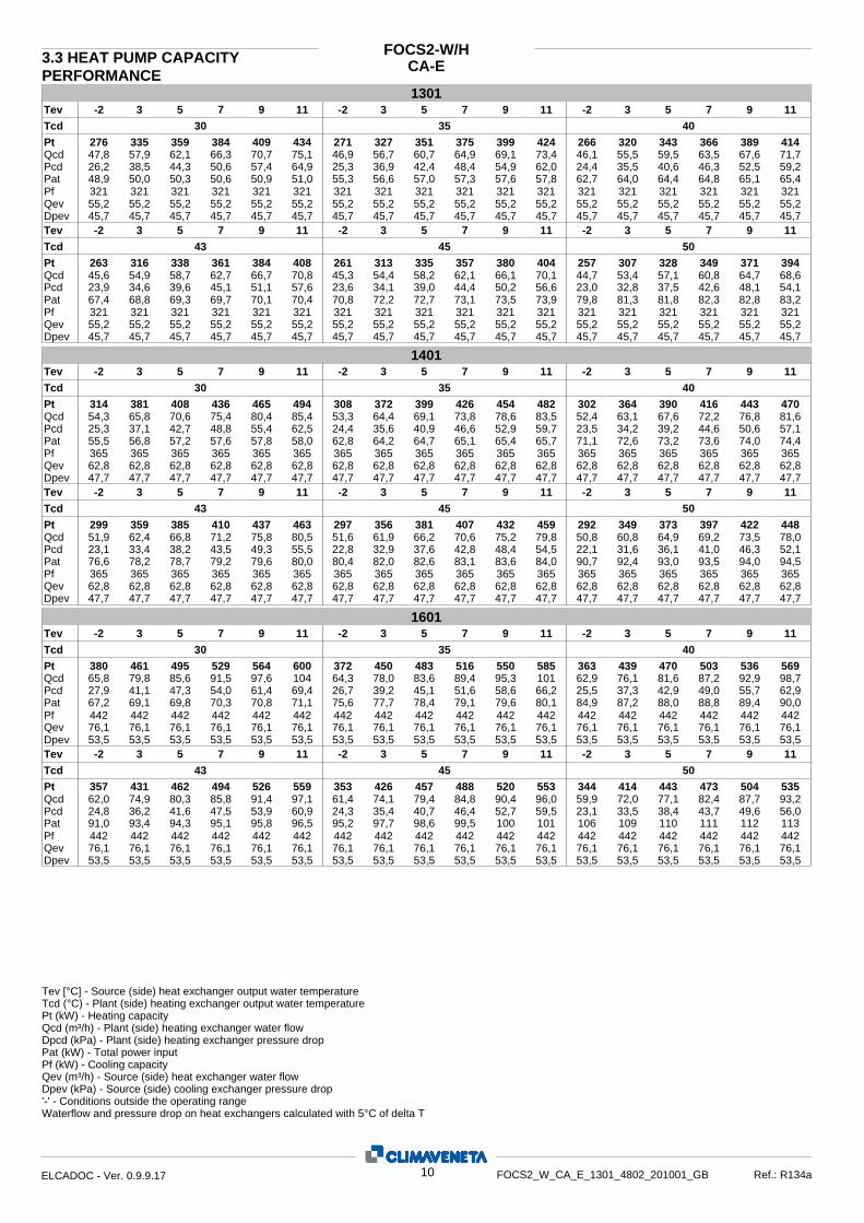
CA-EFOCS2-W/H3.3 HEAT PUMP CAPACITY
PERFORMANCE 1301
5 7 9 11 -2 3 5 7 9 11-2 3 5 7 9 11-2 3 30 35 40
276
48,9
47,8 26,2
Tcd Pt
Pat
Qcd Pcd
335 359 384 409 434 271 327 351 375 399 424 266 320 343 366 389 414
50,0 50,3 50,6 50,9 51,0 55,3 56,6 57,0 57,3 57,6 57,8 62,7 64,0 64,4 64,8 65,1 65,4
57,9 62,1 66,3 70,7 75,1 46,9 56,7 60,7 64,9 69,1 73,4 46,1 55,5 59,5 63,5 67,6 71,738,5 44,3 50,6 57,4 64,9 25,3 36,9 42,4 48,4 54,9 62,0 24,4 35,5 40,6 46,3 52,5 59,2
Tev
Dpev Qev Pf 321 321 321 321 321 321
55,2 55,2 55,2 55,2 55,2 55,2 45,7 45,7 45,7 45,7 45,7 45,7
321 321 321 321 321 32155,2 55,2 55,2 55,2 55,2 55,245,7 45,7 45,7 45,7 45,7 45,7
321 321 321 321 321 32155,2 55,2 55,2 55,2 55,2 55,245,7 45,7 45,7 45,7 45,7 45,7
23,9 Pcd 34,6 39,6 45,1 51,1 57,6 23,6 34,1 39,0 44,4 50,2 56,6 23,0 32,8 37,5 42,6 48,1 54,145,6 Qcd 54,9 58,7 62,7 66,7 70,8 45,3 54,4 58,2 62,1 66,1 70,1 44,7 53,4 57,1 60,8 64,7 68,6
67,4 Pat 68,8 69,3 69,7 70,1 70,4 70,8 72,2 72,7 73,1 73,5 73,9 79,8 81,3 81,8 82,3 82,8 83,2
263 Pt 316 338 361 384 408 261 313 335 357 380 404 257 307 328 349 371 394
43 45 50 Tcd 11 97 5 3 -2 119753-2 1197 5 3 -2Tev
Dpev Qev Pf 321 321 321 321 321 321
55,2 55,2 55,2 55,2 55,2 55,2 45,7 45,7 45,7 45,7 45,7 45,7
321 321 321 321 321 32155,2 55,2 55,2 55,2 55,2 55,245,7 45,7 45,7 45,7 45,7 45,7
321 321 321 321 321 32155,2 55,2 55,2 55,2 55,2 55,245,7 45,7 45,7 45,7 45,7 45,7
14015 7 9 11 -2 3 5 7 9 11-2 3 5 7 9 11-2 3
30 35 40 314
55,5
54,3 25,3
Tcd Pt
Pat
Qcd Pcd
381 408 436 465 494 308 372 399 426 454 482 302 364 390 416 443 470
56,8 57,2 57,6 57,8 58,0 62,8 64,2 64,7 65,1 65,4 65,7 71,1 72,6 73,2 73,6 74,0 74,4
65,8 70,6 75,4 80,4 85,4 53,3 64,4 69,1 73,8 78,6 83,5 52,4 63,1 67,6 72,2 76,8 81,637,1 42,7 48,8 55,4 62,5 24,4 35,6 40,9 46,6 52,9 59,7 23,5 34,2 39,2 44,6 50,6 57,1
Tev
Dpev Qev Pf 365 365 365 365 365 365
62,8 62,8 62,8 62,8 62,8 62,8 47,7 47,7 47,7 47,7 47,7 47,7
365 365 365 365 365 36562,8 62,8 62,8 62,8 62,8 62,847,7 47,7 47,7 47,7 47,7 47,7
365 365 365 365 365 36562,8 62,8 62,8 62,8 62,8 62,847,7 47,7 47,7 47,7 47,7 47,7
23,1 Pcd 33,4 38,2 43,5 49,3 55,5 22,8 32,9 37,6 42,8 48,4 54,5 22,1 31,6 36,1 41,0 46,3 52,151,9 Qcd 62,4 66,8 71,2 75,8 80,5 51,6 61,9 66,2 70,6 75,2 79,8 50,8 60,8 64,9 69,2 73,5 78,0
76,6 Pat 78,2 78,7 79,2 79,6 80,0 80,4 82,0 82,6 83,1 83,6 84,0 90,7 92,4 93,0 93,5 94,0 94,5
299 Pt 359 385 410 437 463 297 356 381 407 432 459 292 349 373 397 422 448
43 45 50 Tcd 11 97 5 3 -2 119753-2 1197 5 3 -2Tev
Dpev Qev Pf 365 365 365 365 365 365
62,8 62,8 62,8 62,8 62,8 62,8 47,7 47,7 47,7 47,7 47,7 47,7
365 365 365 365 365 36562,8 62,8 62,8 62,8 62,8 62,847,7 47,7 47,7 47,7 47,7 47,7
365 365 365 365 365 36562,8 62,8 62,8 62,8 62,8 62,847,7 47,7 47,7 47,7 47,7 47,7
16015 7 9 11 -2 3 5 7 9 11-2 3 5 7 9 11-2 3
30 35 40 380
67,2
65,8 27,9
Tcd Pt
Pat
Qcd Pcd
461 495 529 564 600 372 450 483 516 550 585 363 439 470 503 536 569
69,1 69,8 70,3 70,8 71,1 75,6 77,7 78,4 79,1 79,6 80,1 84,9 87,2 88,0 88,8 89,4 90,0
79,8 85,6 91,5 97,6 104 64,3 78,0 83,6 89,4 95,3 101 62,9 76,1 81,6 87,2 92,9 98,741,1 47,3 54,0 61,4 69,4 26,7 39,2 45,1 51,6 58,6 66,2 25,5 37,3 42,9 49,0 55,7 62,9
Tev
Dpev Qev Pf 442 442 442 442 442 442
76,1 76,1 76,1 76,1 76,1 76,1 53,5 53,5 53,5 53,5 53,5 53,5
442 442 442 442 442 44276,1 76,1 76,1 76,1 76,1 76,153,5 53,5 53,5 53,5 53,5 53,5
442 442 442 442 442 44276,1 76,1 76,1 76,1 76,1 76,153,5 53,5 53,5 53,5 53,5 53,5
24,8 Pcd 36,2 41,6 47,5 53,9 60,9 24,3 35,4 40,7 46,4 52,7 59,5 23,1 33,5 38,4 43,7 49,6 56,062,0 Qcd 74,9 80,3 85,8 91,4 97,1 61,4 74,1 79,4 84,8 90,4 96,0 59,9 72,0 77,1 82,4 87,7 93,2
91,0 Pat 93,4 94,3 95,1 95,8 96,5 95,2 97,7 98,6 99,5 100 101 106 109 110 111 112 113
357 Pt 431 462 494 526 559 353 426 457 488 520 553 344 414 443 473 504 535
43 45 50 Tcd 11 97 5 3 -2 119753-2 1197 5 3 -2Tev
Dpev Qev Pf 442 442 442 442 442 442
76,1 76,1 76,1 76,1 76,1 76,1 53,5 53,5 53,5 53,5 53,5 53,5
442 442 442 442 442 44276,1 76,1 76,1 76,1 76,1 76,153,5 53,5 53,5 53,5 53,5 53,5
442 442 442 442 442 44276,1 76,1 76,1 76,1 76,1 76,153,5 53,5 53,5 53,5 53,5 53,5
Waterflow and pressure drop on heat exchangers calculated with 5°C of delta T'-' - Conditions outside the operating range
Dpcd (kPa) - Plant (side) heating exchanger pressure drop Qcd (m³/h) - Plant (side) heating exchanger water flow
Pat (kW) - Total power input
Pt (kW) - Heating capacity Tcd (°C) - Plant (side) heating exchanger output water temperature
Pf (kW) - Cooling capacity Qev (m³/h) - Source (side) heat exchanger water flow Dpev (kPa) - Source (side) cooling exchanger pressure drop
Tev [°C] - Source (side) heat exchanger output water temperature
10ELCADOC - Ver. 0.9.9.17 FOCS2_W_CA_E_1301_4802_201001_GB Ref.: R134a

CA-EFOCS2-W/HHEAT PUMP CAPACITY
PERFORMANCE 1801
5 7 9 11 -2 3 5 7 9 11-2 3 5 7 9 11-2 3 30 35 40
435
76,7
75,3 28,4
Tcd Pt
Pat
Qcd Pcd
528 567 606 646 687 425 516 553 591 630 670 415 502 538 576 613 652
78,9 79,7 80,3 80,8 81,3 86,3 88,7 89,5 90,3 90,9 91,5 96,9 99,6 101 101 102 103
91,4 98,0 105 112 119 73,7 89,3 95,8 102 109 116 72,0 87,1 93,4 99,8 106 11341,9 48,2 55,2 62,7 70,9 27,2 40,0 46,0 52,6 59,8 67,6 26,0 38,1 43,8 50,0 56,8 64,2
Tev
Dpev Qev Pf 506 506 506 506 506 506
87,2 87,2 87,2 87,2 87,2 87,2 53,4 53,4 53,4 53,4 53,4 53,4
506 506 506 506 506 50687,2 87,2 87,2 87,2 87,2 87,253,4 53,4 53,4 53,4 53,4 53,4
506 506 506 506 506 50687,2 87,2 87,2 87,2 87,2 87,253,4 53,4 53,4 53,4 53,4 53,4
25,3 Pcd 36,9 42,4 48,5 55,0 62,2 24,8 36,1 41,5 47,4 53,8 60,8 23,6 34,2 39,2 44,7 50,7 57,271,0 Qcd 85,8 91,9 98,2 105 111 70,3 84,9 90,9 97,1 104 110 68,5 82,5 88,3 94,3 100 107
104 Pat 107 108 109 109 110 109 112 113 114 115 115 122 125 126 127 128 129
409 Pt 494 529 566 603 641 405 488 523 559 596 633 394 474 507 542 577 613
43 45 50 Tcd 11 97 5 3 -2 119753-2 1197 5 3 -2Tev
Dpev Qev Pf 506 506 506 506 506 506
87,2 87,2 87,2 87,2 87,2 87,2 53,4 53,4 53,4 53,4 53,4 53,4
506 506 506 506 506 50687,2 87,2 87,2 87,2 87,2 87,253,4 53,4 53,4 53,4 53,4 53,4
506 506 506 506 506 50687,2 87,2 87,2 87,2 87,2 87,253,4 53,4 53,4 53,4 53,4 53,4
21015 7 9 11 -2 3 5 7 9 11-2 3 5 7 9 11-2 3
30 35 40 492
86,3
85,1 29,2
Tcd Pt
Pat
Qcd Pcd
598 642 687 732 779 482 584 627 670 714 759 472 571 612 654 697 740
89,3 90,3 91,2 91,9 92,6 97,1 100 102 103 103 104 109 113 114 115 116 117
103 111 119 127 135 83,5 101 109 116 124 132 81,8 99,0 106 113 121 12843,1 49,7 56,8 64,6 73,1 28,1 41,3 47,5 54,3 61,7 69,7 27,0 39,5 45,4 51,8 58,8 66,5
Tev
Dpev Qev Pf 574 574 574 574 574 574
98,8 98,8 98,8 98,8 98,8 98,8 52,8 52,8 52,8 52,8 52,8 52,8
574 574 574 574 574 57498,8 98,8 98,8 98,8 98,8 98,852,8 52,8 52,8 52,8 52,8 52,8
574 574 574 574 574 57498,8 98,8 98,8 98,8 98,8 98,852,8 52,8 52,8 52,8 52,8 52,8
26,4 Pcd 38,5 44,2 50,4 57,2 64,5 26,0 37,8 43,4 49,5 56,1 63,3 25,1 36,2 41,4 47,2 53,4 60,280,9 Qcd 97,7 105 112 119 127 80,3 96,9 104 111 118 125 78,9 94,8 101 108 115 122
117 Pat 121 122 123 124 126 122 126 128 129 130 131 137 141 143 144 145 147
466 Pt 563 603 644 686 729 462 557 597 638 679 721 453 544 582 621 661 702
43 45 50 Tcd 11 97 5 3 -2 119753-2 1197 5 3 -2Tev
Dpev Qev Pf 574 574 574 574 574 574
98,8 98,8 98,8 98,8 98,8 98,8 52,8 52,8 52,8 52,8 52,8 52,8
574 574 574 574 574 57498,8 98,8 98,8 98,8 98,8 98,852,8 52,8 52,8 52,8 52,8 52,8
574 574 574 574 574 57498,8 98,8 98,8 98,8 98,8 98,852,8 52,8 52,8 52,8 52,8 52,8
24015 7 9 11 -2 3 5 7 9 11-2 3 5 7 9 11-2 3
30 35 40 558
97,7
96,5 30,3
Tcd Pt
Pat
Qcd Pcd
677 727 777 829 881 546 662 710 759 808 859 535 646 693 740 788 838
101 102 103 104 105 110 114 115 116 117 118 124 128 129 130 132 133
117 126 134 143 152 94,5 115 123 131 140 149 92,7 112 120 128 137 14544,7 51,5 58,9 67,0 75,7 29,1 42,8 49,2 56,3 63,9 72,2 28,0 41,0 47,1 53,7 61,0 68,8
Tev
Dpev Qev Pf 649 649 649 649 649 649
112 112 112 112 112 112 60,2 60,2 60,2 60,2 60,2 60,2
649 649 649 649 649 649112 112 112 112 112 11260,2 60,2 60,2 60,2 60,2 60,2
649 649 649 649 649 649112 112 112 112 112 11260,2 60,2 60,2 60,2 60,2 60,2
27,4 Pcd 39,9 45,8 52,3 59,3 66,9 27,0 39,2 45,0 51,3 58,1 65,6 26,0 37,6 43,0 48,9 55,4 62,491,7 Qcd 111 119 127 135 143 91,0 110 117 125 134 142 89,4 107 115 122 130 138
132 Pat 137 138 140 141 142 139 143 145 146 147 149 155 160 161 163 165 166
528 Pt 637 683 729 776 825 524 631 676 722 768 816 513 616 660 704 749 795
43 45 50 Tcd 11 97 5 3 -2 119753-2 1197 5 3 -2Tev
Dpev Qev Pf 649 649 649 649 649 649
112 112 112 112 112 112 60,2 60,2 60,2 60,2 60,2 60,2
649 649 649 649 649 649112 112 112 112 112 11260,2 60,2 60,2 60,2 60,2 60,2
649 649 649 649 649 649112 112 112 112 112 11260,2 60,2 60,2 60,2 60,2 60,2
Waterflow and pressure drop on heat exchangers calculated with 5°C of delta T'-' - Conditions outside the operating range
Dpcd (kPa) - Plant (side) heating exchanger pressure drop Qcd (m³/h) - Plant (side) heating exchanger water flow
Pat (kW) - Total power input
Pt (kW) - Heating capacity Tcd (°C) - Plant (side) heating exchanger output water temperature
Pf (kW) - Cooling capacity Qev (m³/h) - Source (side) heat exchanger water flow Dpev (kPa) - Source (side) cooling exchanger pressure drop
Tev [°C] - Source (side) heat exchanger output water temperature
11ELCADOC - Ver. 0.9.9.17 FOCS2_W_CA_E_1301_4802_201001_GB Ref.: R134a

CA-EFOCS2-W/HHEAT PUMP CAPACITY
PERFORMANCE 2802
5 7 9 11 -2 3 5 7 9 11-2 3 5 7 9 11-2 3 30 35 40
629
111
109 25,3
Tcd Pt
Pat
Qcd Pcd
761 816 872 930 988 616 744 798 852 907 964 604 728 780 832 886 941
114 115 115 116 116 126 129 130 130 131 132 142 145 146 147 148 149
132 141 151 161 171 107 129 138 148 157 167 105 126 135 144 154 16337,1 42,7 48,7 55,3 62,5 24,3 35,6 40,8 46,6 52,9 59,7 23,5 34,1 39,1 44,6 50,6 57,0
Tev
Dpev Qev Pf 729 729 729 729 729 729
126 126 126 126 126 126 51,9 51,9 51,9 51,9 51,9 51,9
729 729 729 729 729 729126 126 126 126 126 12651,9 51,9 51,9 51,9 51,9 51,9
729 729 729 729 729 729126 126 126 126 126 12651,9 51,9 51,9 51,9 51,9 51,9
23,0 Pcd 33,3 38,2 43,5 49,2 55,5 22,8 32,8 37,6 42,7 48,4 54,5 22,1 31,6 36,1 41,0 46,3 52,1104 Qcd 125 134 143 152 161 103 124 132 141 150 160 102 122 130 138 147 156
153 Pat 156 158 159 159 160 161 164 165 166 167 168 182 185 186 187 188 189
598 Pt 719 769 821 873 927 593 713 762 813 865 918 584 698 746 795 845 896
43 45 50 Tcd 11 97 5 3 -2 119753-2 1197 5 3 -2Tev
Dpev Qev Pf 729 729 729 729 729 729
126 126 126 126 126 126 51,9 51,9 51,9 51,9 51,9 51,9
729 729 729 729 729 729126 126 126 126 126 12651,9 51,9 51,9 51,9 51,9 51,9
729 729 729 729 729 729126 126 126 126 126 12651,9 51,9 51,9 51,9 51,9 51,9
32025 7 9 11 -2 3 5 7 9 11-2 3 5 7 9 11-2 3
30 35 40 761
134
132 27,9
Tcd Pt
Pat
Qcd Pcd
923 990 1059 1129 1200 743 901 966 1033 1101 1170 725 877 941 1005 1071 1139
138 140 141 142 142 151 155 157 158 159 160 170 174 176 178 179 180
160 171 183 195 208 129 156 167 179 191 203 126 152 163 174 186 19841,0 47,2 54,0 61,3 69,3 26,7 39,2 45,1 51,5 58,5 66,1 25,5 37,3 42,9 49,0 55,6 62,8
Tev
Dpev Qev Pf 884 884 884 884 884 884
152 152 152 152 152 152 58,6 58,6 58,6 58,6 58,6 58,6
884 884 884 884 884 884152 152 152 152 152 15258,6 58,6 58,6 58,6 58,6 58,6
884 884 884 884 884 884152 152 152 152 152 15258,6 58,6 58,6 58,6 58,6 58,6
24,8 Pcd 36,2 41,5 47,4 53,8 60,8 24,3 35,4 40,6 46,4 52,6 59,4 23,1 33,4 38,3 43,7 49,6 56,0124 Qcd 150 161 172 183 194 123 148 159 170 181 192 120 144 154 165 175 186
182 Pat 187 189 190 192 193 190 195 197 199 201 202 213 218 220 222 224 226
714 Pt 863 925 988 1053 1119 707 853 914 977 1040 1106 688 828 886 946 1008 1071
43 45 50 Tcd 11 97 5 3 -2 119753-2 1197 5 3 -2Tev
Dpev Qev Pf 884 884 884 884 884 884
152 152 152 152 152 152 58,6 58,6 58,6 58,6 58,6 58,6
884 884 884 884 884 884152 152 152 152 152 15258,6 58,6 58,6 58,6 58,6 58,6
884 884 884 884 884 884152 152 152 152 152 15258,6 58,6 58,6 58,6 58,6 58,6
36025 7 9 11 -2 3 5 7 9 11-2 3 5 7 9 11-2 3
30 35 40 870
153
150 28,5
Tcd Pt
Pat
Qcd Pcd
1056 1133 1212 1292 1373 850 1031 1105 1182 1260 1339 830 1004 1076 1150 1226 1303
158 159 160 162 162 172 177 179 180 182 183 194 199 201 203 204 206
183 196 210 223 238 147 178 191 205 218 232 144 174 187 200 213 22642,0 48,4 55,3 62,9 71,1 27,3 40,1 46,2 52,8 60,0 67,8 26,1 38,2 43,9 50,2 57,0 64,4
Tev
Dpev Qev Pf 1012 1012 1012 1012 1012 1012
174 174 174 174 174 174 41,3 41,3 41,3 41,3 41,3 41,3
1012 1012 1012 1012 1012 1012174 174 174 174 174 17441,3 41,3 41,3 41,3 41,3 41,3
1012 1012 1012 1012 1012 1012174 174 174 174 174 17441,3 41,3 41,3 41,3 41,3 41,3
25,4 Pcd 37,0 42,6 48,6 55,2 62,3 24,9 36,3 41,6 47,5 53,9 60,9 23,7 34,3 39,3 44,8 50,8 57,4142 Qcd 171 184 196 209 222 141 170 182 194 207 220 137 165 177 189 201 213
208 Pat 213 215 217 219 220 217 223 225 227 229 231 243 249 252 254 256 258
817 Pt 987 1058 1131 1205 1281 809 976 1046 1118 1191 1266 787 947 1014 1083 1154 1226
43 45 50 Tcd 11 97 5 3 -2 119753-2 1197 5 3 -2Tev
Dpev Qev Pf 1012 1012 1012 1012 1012 1012
174 174 174 174 174 174 41,3 41,3 41,3 41,3 41,3 41,3
1012 1012 1012 1012 1012 1012174 174 174 174 174 17441,3 41,3 41,3 41,3 41,3 41,3
1012 1012 1012 1012 1012 1012174 174 174 174 174 17441,3 41,3 41,3 41,3 41,3 41,3
Waterflow and pressure drop on heat exchangers calculated with 5°C of delta T'-' - Conditions outside the operating range
Dpcd (kPa) - Plant (side) heating exchanger pressure drop Qcd (m³/h) - Plant (side) heating exchanger water flow
Pat (kW) - Total power input
Pt (kW) - Heating capacity Tcd (°C) - Plant (side) heating exchanger output water temperature
Pf (kW) - Cooling capacity Qev (m³/h) - Source (side) heat exchanger water flow Dpev (kPa) - Source (side) cooling exchanger pressure drop
Tev [°C] - Source (side) heat exchanger output water temperature
12ELCADOC - Ver. 0.9.9.17 FOCS2_W_CA_E_1301_4802_201001_GB Ref.: R134a
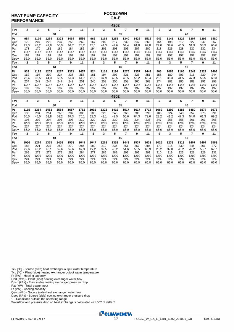
CA-EFOCS2-W/HHEAT PUMP CAPACITY
PERFORMANCE 4202
5 7 9 11 -2 3 5 7 9 11-2 3 5 7 9 11-2 3 30 35 40
984
173
170 29,3
Tcd Pt
Pat
Qcd Pcd
1196 1284 1373 1464 1556 963 1168 1253 1340 1428 1518 943 1141 1223 1307 1393 1480
179 181 182 184 185 194 201 203 205 207 209 218 226 228 230 232 234
207 222 237 253 269 167 202 217 232 247 263 164 198 212 227 242 25743,2 49,8 56,9 64,7 73,2 28,1 41,3 47,6 54,4 61,8 69,8 27,0 39,6 45,5 51,9 58,9 66,6
Tev
Dpev Qev Pf 1147 1147 1147 1147 1147 1147
197 197 197 197 197 197 55,0 55,0 55,0 55,0 55,0 55,0
1147 1147 1147 1147 1147 1147197 197 197 197 197 19755,0 55,0 55,0 55,0 55,0 55,0
1147 1147 1147 1147 1147 1147197 197 197 197 197 19755,0 55,0 55,0 55,0 55,0 55,0
26,4 Pcd 38,5 44,3 50,5 57,3 64,7 26,1 37,9 43,5 49,5 56,2 63,4 25,1 36,3 41,5 47,3 53,5 60,3162 Qcd 195 209 224 238 253 161 194 207 221 236 251 158 189 203 216 230 244
234 Pat 242 244 247 249 251 245 253 256 258 260 263 274 282 285 288 291 293
932 Pt 1125 1205 1287 1371 1457 924 1114 1194 1275 1357 1442 906 1089 1165 1242 1322 1403
43 45 50 Tcd 11 97 5 3 -2 119753-2 1197 5 3 -2Tev
Dpev Qev Pf 1147 1147 1147 1147 1147 1147
197 197 197 197 197 197 55,0 55,0 55,0 55,0 55,0 55,0
1147 1147 1147 1147 1147 1147197 197 197 197 197 19755,0 55,0 55,0 55,0 55,0 55,0
1147 1147 1147 1147 1147 1147197 197 197 197 197 19755,0 55,0 55,0 55,0 55,0 55,0
48025 7 9 11 -2 3 5 7 9 11-2 3 5 7 9 11-2 3
30 35 40 1115
195
193 30,5
Tcd Pt
Pat
Qcd Pcd
1354 1453 1554 1657 1762 1092 1323 1419 1517 1617 1718 1069 1292 1385 1480 1577 1675
202 204 206 208 210 220 227 230 232 234 236 247 255 258 261 263 265
234 251 269 287 305 189 229 246 263 280 298 185 224 240 257 273 29145,0 51,8 59,2 67,3 76,1 29,3 43,1 49,5 56,6 64,3 72,6 28,2 41,2 47,3 54,0 61,3 69,2
Tev
Dpev Qev Pf 1299 1299 1299 1299 1299 1299
224 224 224 224 224 224 65,0 65,0 65,0 65,0 65,0 65,0
1299 1299 1299 1299 1299 1299224 224 224 224 224 22465,0 65,0 65,0 65,0 65,0 65,0
1299 1299 1299 1299 1299 1299224 224 224 224 224 22465,0 65,0 65,0 65,0 65,0 65,0
27,6 Pcd 40,2 46,1 52,6 59,6 67,3 27,2 39,5 45,2 51,6 58,5 65,9 26,2 37,8 43,2 49,2 55,7 62,7183 Qcd 221 237 253 270 286 182 219 235 251 267 284 179 215 230 245 261 277
265 Pat 273 276 279 282 284 277 286 289 292 295 297 310 319 323 326 329 332
1056 Pt 1274 1365 1458 1553 1649 1047 1262 1352 1443 1537 1632 1026 1233 1319 1407 1497 1589
43 45 50 Tcd 11 97 5 3 -2 119753-2 1197 5 3 -2Tev
Dpev Qev Pf 1299 1299 1299 1299 1299 1299
224 224 224 224 224 224 65,0 65,0 65,0 65,0 65,0 65,0
1299 1299 1299 1299 1299 1299224 224 224 224 224 22465,0 65,0 65,0 65,0 65,0 65,0
1299 1299 1299 1299 1299 1299224 224 224 224 224 22465,0 65,0 65,0 65,0 65,0 65,0
Waterflow and pressure drop on heat exchangers calculated with 5°C of delta T'-' - Conditions outside the operating range
Dpcd (kPa) - Plant (side) heating exchanger pressure drop Qcd (m³/h) - Plant (side) heating exchanger water flow
Pat (kW) - Total power input
Pt (kW) - Heating capacity Tcd (°C) - Plant (side) heating exchanger output water temperature
Pf (kW) - Cooling capacity Qev (m³/h) - Source (side) heat exchanger water flow Dpev (kPa) - Source (side) cooling exchanger pressure drop
Tev [°C] - Source (side) heat exchanger output water temperature
13ELCADOC - Ver. 0.9.9.17 FOCS2_W_CA_E_1301_4802_201001_GB Ref.: R134a

CA-E3.4 DESUPERHEATER CAPACITY PERFOR.
FOCS2-W / D
1301
30 35 40 43 45 50
35 40 45 35 40 45 35 40 45 35 40 45 35 40 45 35 40 45
Pf Pat Ptde Qde Dpde
349 349 349 333 333 333 316 316 316 306 306 306 300 300 300 282 282 28248,9 48,9 48,9 55,3 55,3 55,3 62,5 62,5 62,5 67,3 67,3 67,3 70,6 70,6 70,6 79,4 79,4 79,425,3 17,4 4,79 44,2 36,5 24,8 63,1 55,9 44,6 74,0 67,2 56,1 81,0 74,4 63,3 96,8 90,8 79,24,39 3,02 0,832 7,65 6,34 4,30 10,9 9,69 7,76 12,8 11,6 9,75 14,0 12,9 11,0 16,8 15,7 13,826,4 12,5 0,949 80,1 55,0 25,3 163 129 82,5 225 186 130 270 228 166 385 340 259
Tde Tcd
1401
30 35 40 43 45 50
35 40 45 35 40 45 35 40 45 35 40 45 35 40 45 35 40 45
Pf Pat Ptde Qde Dpde
396 396 396 378 378 378 360 360 360 348 348 348 341 341 341 321 321 32155,5 55,5 55,5 62,8 62,8 62,8 71,0 71,0 71,0 76,4 76,4 76,4 80,2 80,2 80,2 90,3 90,3 90,328,8 19,8 5,44 50,2 41,5 28,1 71,6 63,5 50,7 84,1 76,3 63,7 92,1 84,5 71,9 110 103 90,04,99 3,43 0,946 8,69 7,20 4,89 12,4 11,0 8,81 14,6 13,2 11,1 15,9 14,7 12,5 19,0 17,9 15,634,1 16,1 1,23 103 71,0 32,7 211 166 106 291 240 168 348 294 214 497 438 335
Tde Tcd
1601
30 35 40 43 45 50
35 40 45 35 40 45 35 40 45 35 40 45 35 40 45 35 40 45
Pf Pat Ptde Qde Dpde
480 480 480 458 458 458 435 435 435 420 420 420 409 409 409 382 382 38267,9 67,9 67,9 76,3 76,3 76,3 85,7 85,7 85,7 91,7 91,7 91,7 96,0 96,0 96,0 107 107 10735,2 24,2 6,65 60,9 50,4 34,2 86,4 76,5 61,2 101 91,6 76,5 110 101 86,1 131 123 1076,10 4,19 1,16 10,6 8,74 5,93 15,0 13,3 10,6 17,5 15,9 13,3 19,1 17,5 15,0 22,6 21,3 18,633,8 16,0 1,22 101 69,6 32,1 204 160 103 278 230 161 332 280 204 466 411 314
Tde Tcd
1801
30 35 40 43 45 50
35 40 45 35 40 45 35 40 45 35 40 45 35 40 45 35 40 45
Pf Pat Ptde Qde Dpde
551 551 551 525 525 525 498 498 498 481 481 481 469 469 469 438 438 43877,5 77,5 77,5 87,1 87,1 87,1 97,8 97,8 97,8 105 105 105 110 110 110 123 123 12340,2 27,6 7,59 69,6 57,6 39,0 98,7 87,4 69,9 115 105 87,4 126 116 98,4 149 140 1226,96 4,78 1,32 12,0 9,98 6,78 17,1 15,2 12,1 20,0 18,2 15,2 21,8 20,1 17,1 25,9 24,3 21,229,1 13,7 1,04 87,1 59,8 27,6 175 138 88,4 240 198 138 285 241 175 401 354 271
Tde Tcd
2101
30 35 40 43 45 50
35 40 45 35 40 45 35 40 45 35 40 45 35 40 45 35 40 45
Pf Pat Ptde Qde Dpde
624 624 624 595 595 595 566 566 566 548 548 548 536 536 536 504 504 50488,0 88,0 88,0 99,0 99,0 99,0 111 111 111 119 119 119 125 125 125 139 139 13945,6 31,3 8,62 79,0 65,4 44,3 112 99,3 79,4 131 119 99,3 143 131 112 169 159 1397,91 5,43 1,50 13,7 11,3 7,70 19,4 17,2 13,8 22,7 20,6 17,2 24,8 22,8 19,4 29,3 27,6 24,137,5 17,7 1,35 112 77,2 35,6 226 178 114 309 255 179 368 311 226 517 456 348
Tde Tcd
2401
30 35 40 43 45 50
35 40 45 35 40 45 35 40 45 35 40 45 35 40 45 35 40 45
Pf Pat Ptde Qde Dpde
706 706 706 674 674 674 641 641 641 620 620 620 606 606 606 571 571 57199,6 99,6 99,6 112 112 112 126 126 126 135 135 135 141 141 141 157 157 15751,7 35,5 9,76 89,5 74,0 50,2 127 112 89,9 148 135 112 162 149 126 192 180 1578,95 6,15 1,70 15,5 12,8 8,72 22,0 19,5 15,6 25,7 23,3 19,5 28,0 25,8 22,0 33,2 31,2 27,348,1 22,7 1,73 144 99,0 45,6 290 228 146 396 327 229 471 398 290 661 584 446
Tde Tcd
Tcd [°C] - Source (side) cooling exchanger output water temperaturePf (kW) - Cooling capacity (Plant side cooling exchanger water in/out 12/7 °C)Pat (kW) - Total power input Ptde (kW) - Heat recovery thermal capacity Qde (m3/h) - Plant (side) cooling exchanger recovery water flow Dpde (kPa) - Plant side heating exchanger recovery pressure drop'-' - Conditions outside the operating range Waterflow and pressure drop on heat exchangers calculated with 5°C of delta T
Tde (°C) - Plant (side) heating exchanger recovery output water temperature
14ELCADOC - Ver. 0.9.9.17 FOCS2_W_CA_E_1301_4802_201001_GB Ref.: R134a

CA-EDESUPERHEATER CAPACITY PERFOR.
FOCS2-W / D
2802
30 35 40 43 45 50
35 40 45 35 40 45 35 40 45 35 40 45 35 40 45 35 40 45
Pf Pat Ptde Qde Dpde
793 793 793 757 757 757 720 720 720 697 697 697 681 681 681 642 642 642111 111 111 126 126 126 142 142 142 153 153 153 161 161 161 181 181 18157,7 39,6 10,9 100 83,1 56,3 143 127 102 168 153 128 184 169 144 220 206 1809,99 6,87 1,89 17,4 14,4 9,78 24,8 22,0 17,6 29,2 26,5 22,2 31,9 29,4 25,0 38,1 35,8 31,334,2 16,2 1,23 104 71,3 32,8 212 167 107 292 241 169 350 295 215 499 440 336
Tde Tcd
3202
30 35 40 43 45 50
35 40 45 35 40 45 35 40 45 35 40 45 35 40 45 35 40 45
Pf Pat Ptde Qde Dpde
961 961 961 917 917 917 870 870 870 840 840 840 819 819 819 765 765 765136 136 136 153 153 153 171 171 171 184 184 184 192 192 192 215 215 21570,4 48,3 13,3 122 101 68,3 173 153 122 202 183 153 220 202 172 261 245 21412,2 8,38 2,31 21,1 17,5 11,9 29,9 26,6 21,3 35,0 31,8 26,6 38,2 35,1 29,9 45,3 42,5 37,233,9 16,0 1,22 102 69,7 32,1 204 161 103 279 230 161 332 281 204 467 412 315
Tde Tcd
3602
30 35 40 43 45 50
35 40 45 35 40 45 35 40 45 35 40 45 35 40 45 35 40 45
Pf Pat Ptde Qde Dpde
1101 1101 1101 1050 1050 1050 996 996 996 962 962 962 938 938 938 876 876 876155 155 155 174 174 174 195 195 195 209 209 209 219 219 219 245 245 24580,3 55,1 15,2 139 115 77,9 197 175 140 230 209 175 252 231 197 298 280 24413,9 9,56 2,64 24,1 19,9 13,5 34,1 30,3 24,3 39,9 36,3 30,3 43,6 40,1 34,2 51,7 48,5 42,429,0 13,7 1,04 86,9 59,7 27,5 175 138 88,2 239 197 138 285 241 175 401 354 270
Tde Tcd
4202
30 35 40 43 45 50
35 40 45 35 40 45 35 40 45 35 40 45 35 40 45 35 40 45
Pf Pat Ptde Qde Dpde
1246 1246 1246 1190 1190 1190 1131 1131 1131 1095 1095 1095 1071 1071 1071 1008 1008 1008176 176 176 198 198 198 222 222 222 238 238 238 249 249 249 278 278 27891,3 62,6 17,2 158 131 88,6 224 199 159 262 238 199 286 262 223 339 318 27715,8 10,9 3,00 27,4 22,7 15,4 38,8 34,5 27,6 45,4 41,2 34,5 49,5 45,5 38,8 58,7 55,1 48,237,5 17,7 1,35 112 77,2 35,6 226 178 114 309 255 178 368 311 226 517 456 348
Tde Tcd
4802
30 35 40 43 45 50
35 40 45 35 40 45 35 40 45 35 40 45 35 40 45 35 40 45
Pf Pat Ptde Qde Dpde
1411 1411 1411 1347 1347 1347 1281 1281 1281 1240 1240 1240 1212 1212 1212 1142 1142 1142199 199 199 224 224 224 252 252 252 269 269 269 282 282 282 315 315 315103 70,9 19,5 179 148 100 254 225 180 297 269 225 324 297 253 383 360 31417,9 12,3 3,39 31,0 25,7 17,4 44,0 39,0 31,2 51,4 46,7 39,0 56,1 51,5 43,9 66,4 62,4 54,548,1 22,7 1,73 144 99,0 45,6 290 228 146 396 327 229 471 398 290 661 584 446
Tde Tcd
Tcd [°C] - Source (side) cooling exchanger output water temperaturePf (kW) - Cooling capacity (Plant side cooling exchanger water in/out 12/7 °C)Pat (kW) - Total power input Ptde (kW) - Heat recovery thermal capacity Qde (m3/h) - Plant (side) cooling exchanger recovery water flow Dpde (kPa) - Plant side heating exchanger recovery pressure drop'-' - Conditions outside the operating range Waterflow and pressure drop on heat exchangers calculated with 5°C of delta T
Tde (°C) - Plant (side) heating exchanger recovery output water temperature
15ELCADOC - Ver. 0.9.9.17 FOCS2_W_CA_E_1301_4802_201001_GB Ref.: R134a
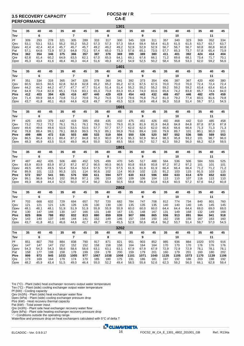
CA-E3.5 RECOVERY CAPACITY PERFORMANCE
FOCS2-W / R
130135 40 45 35 40 45 35 40 45 35 40 45 35 40 45 35 40 45Tre
Tev 6 7 8 9 10 11
Pf Qev Dpev
Ptre Pat
Qre Dpre
309 293 278 321 305 289 333 317 300 345 328 311 357 340 323 369 352 33453,1 53,1 53,1 55,2 55,2 55,2 57,3 57,3 57,3 59,4 59,4 59,4 61,5 61,5 61,5 63,7 63,7 63,742,4 42,4 42,4 45,7 45,7 45,7 49,2 49,2 49,2 52,9 52,9 52,9 56,7 56,7 56,7 60,8 60,8 60,8
362 354 346 375 366 357 387 378 369 399 389 380 411 401 392 424 414 40457,1 64,6 72,9 57,3 64,8 73,1 57,4 65,0 73,3 57,6 73,565,1 57,7 65,3 73,7 57,8 65,4 73,9
62,8 61,4 60,2 64,9 63,5 62,1 67,0 65,5 64,1 69,1 67,6 66,1 71,2 69,6 68,1 73,4 71,7 70,145,3 43,4 41,6 48,4 46,3 44,4 51,6 49,3 47,2 54,9 52,5 50,2 58,4 55,8 53,3 62,0 59,2 56,6
140135 40 45 35 40 45 35 40 45 35 40 45 35 40 45 35 40 45Tre
Tev 6 7 8 9 10 11
Pf Qev Dpev Ptre Pat
Qre Dpre
351 334 316 365 347 328 378 360 341 392 373 354 406 387 367 420 400 38060,5 60,5 60,5 62,8 62,8 62,8 65,2 65,2 65,2 67,5 67,5 67,5 70,0 70,0 70,0 72,4 72,4 72,444,2 44,2 44,2 47,7 47,7 47,7 51,4 51,4 51,4 55,2 55,2 55,2 59,2 59,2 59,2 63,4 63,4 63,4
412 403 394 426 416 407 440 429 419 454 443 432 468 457 446 482 470 45964,9 73,4 82,8 65,1 73,6 83,1 65,3 73,8 83,3 65,4 83,674,0 65,6 74,2 83,8 65,7 74,4 84,0
71,4 69,9 68,4 73,8 72,2 70,6 76,2 74,5 72,9 78,6 76,8 75,2 81,0 79,2 77,4 83,5 81,6 79,843,7 41,8 40,1 46,6 44,6 42,8 49,7 47,6 45,5 52,9 50,6 48,4 56,3 53,8 51,4 59,7 57,1 54,5
160135 40 45 35 40 45 35 40 45 35 40 45 35 40 45 35 40 45Tre
Tev 6 7 8 9 10 11
Pf Qev Dpev
Ptre Pat
Qre Dpre
425 403 379 442 419 395 459 435 410 475 451 426 492 468 442 510 485 45873,2 73,2 73,2 76,1 76,1 76,1 79,0 79,0 79,0 81,9 81,9 81,9 84,8 84,8 84,8 87,8 87,8 87,849,6 49,6 49,6 53,5 53,5 53,5 57,7 57,7 57,7 62,0 62,0 62,0 66,6 66,6 66,6 71,3 71,3 71,3
499 486 472 516 503 488 533 519 504 550 536 520 567 552 536 585 569 55378,8 88,4 99,1 79,1 88,8 99,5 79,3 89,1 99,9 79,6 10089,4 79,9 89,7 101 80,1 90,0 101
86,5 84,4 82,1 89,4 87,2 84,8 92,3 90,0 87,6 95,3 92,9 90,4 98,3 95,8 93,2 101 98,7 96,048,3 45,9 43,5 51,6 49,0 46,4 55,0 52,3 49,5 58,6 55,7 52,7 62,3 59,2 56,0 66,2 62,9 59,5
180135 40 45 35 40 45 35 40 45 35 40 45 35 40 45 35 40 45Tre
Tev 6 7 8 9 10 11
Pf Qev Dpev
Ptre Pat
Qre Dpre
487 462 435 506 480 452 525 499 470 545 517 488 564 536 506 584 555 52583,9 83,9 83,9 87,2 87,2 87,2 90,5 90,5 90,5 93,8 93,8 93,8 97,2 97,2 97,2 101 101 10149,5 49,5 49,5 53,4 53,4 53,4 57,5 57,5 57,5 61,9 61,9 61,9 66,4 66,4 66,4 71,2 71,2 71,2
572 557 541 591 576 559 611 594 577 630 613 596 650 633 614 670 652 63389,9 101 113 90,3 101 114 90,6 102 114 90,9 115102 91,2 103 115 91,5 103 115
99,1 96,6 94,0 102 99,8 97,1 106 103 100 109 106 104 113 110 107 116 113 11049,3 46,9 44,4 52,6 50,0 47,4 56,2 53,4 50,5 59,8 56,8 53,8 63,6 60,5 57,2 67,6 64,2 60,8
280235 40 45 35 40 45 35 40 45 35 40 45 35 40 45 35 40 45Tre
Tev 6 7 8 9 10 11
Pf Qev Dpev
Ptre Pat
Qre Dpre
702 668 632 729 694 657 757 720 682 784 747 708 812 774 734 840 801 760121 121 121 126 126 126 130 130 130 135 135 135 140 140 140 145 145 14548,1 48,1 48,1 51,9 51,9 51,9 55,9 55,9 55,9 60,0 60,0 60,0 64,4 64,4 64,4 69,0 69,0 69,0
825 806 788 852 832 813 880 859 839 907 886 865 936 913 891 964 941 918130 147 166 130 147 166 131 148 167 131 167148 131 149 168 132 149 168
143 140 137 148 144 141 152 149 146 157 154 150 162 158 155 167 163 16043,7 41,8 40,1 46,6 44,6 42,7 49,7 47,5 45,5 52,9 50,6 48,4 56,2 53,7 51,4 59,7 57,0 54,5
320235 40 45 35 40 45 35 40 45 35 40 45 35 40 45 35 40 45Tre
Tev 6 7 8 9 10 11
Pf Qev Dpev
Ptre Pat
Qre Dpre
851 807 759 884 838 790 917 871 821 951 903 852 985 936 884 1020 970 916147 147 147 152 152 152 158 158 158 164 164 164 170 170 170 176 176 17654,3 54,3 54,3 58,6 58,6 58,6 63,1 63,1 63,1 67,9 67,9 67,9 72,9 72,9 72,9 78,1 78,1 78,1
999 973 945 1033 1005 977 1067 1038 1008 1101 1071 1040 1135 1105 1073 1170 1139 1106158 177 198 158 178 199 159 178 200 159 201179 160 179 201 160 180 202
173 169 164 179 174 170 185 180 175 191 186 181 197 192 186 203 198 19248,2 45,9 43,4 51,5 49,0 46,4 55,0 52,2 49,4 58,5 55,6 52,6 62,3 59,2 56,0 66,1 62,8 59,4
Tre (°C) - Plant (side) heat exchanger recovery output water temperatureTev (°C) - Plant (side) cooling exchanger output water temperaturePf (kW) - Cooling capacity Qev (m3/h) - Plant (side) heat exchanger water flow Dpev (kPa) - Plant (side) cooling exchanger pressure drop Ptre (kW) - Heat recovery thermal capacity Pat (kW) - Total power input Qre (m3/h) - Plant side heat exchanger recovery water flow Dpre (kPa) - Plant side heating exchanger recovery pressure drop'-' - Conditions outside the operating range Waterflow and pressure drop on heat exchangers calculated with 5°C of delta T
16ELCADOC - Ver. 0.9.9.17 FOCS2_W_CA_E_1301_4802_201001_GB Ref.: R134a

CA-ERECOVERY CAPACITY PERFORMANCE
FOCS2-W / R
360235 40 45 35 40 45 35 40 45 35 40 45 35 40 45 35 40 45Tre
Tev 6 7 8 9 10 11
Pf Qev Dpev
Ptre Pat
Qre Dpre
975 924 869 1012 960 904 1050 997 940 1089 1034 976 1128 1072 1012 1168 1110 1049168 168 168 174 174 174 181 181 181 188 188 188 194 194 194 201 201 20138,3 38,3 38,3 41,3 41,3 41,3 44,5 44,5 44,5 47,9 47,9 47,9 51,4 51,4 51,4 55,0 55,0 55,0
1143 1113 1082 1182 1150 1118 1221 1188 1154 1260 1226 1191 1299 1265 1228 1339 1303 1266180 202 226 180 203 227 181 203 228 182 229204 182 205 230 183 206 231
198 193 188 205 200 194 211 206 201 218 213 207 225 219 213 232 226 22049,4 47,0 44,5 52,8 50,2 47,5 56,3 53,5 50,7 60,0 57,0 53,9 63,8 60,6 57,4 67,8 64,4 60,9
Tre (°C) - Plant (side) heat exchanger recovery output water temperatureTev (°C) - Plant (side) cooling exchanger output water temperaturePf (kW) - Cooling capacity Qev (m3/h) - Plant (side) heat exchanger water flow Dpev (kPa) - Plant (side) cooling exchanger pressure drop Ptre (kW) - Heat recovery thermal capacity Pat (kW) - Total power input Qre (m3/h) - Plant side heat exchanger recovery water flow Dpre (kPa) - Plant side heating exchanger recovery pressure drop'-' - Conditions outside the operating range Waterflow and pressure drop on heat exchangers calculated with 5°C of delta T
17ELCADOC - Ver. 0.9.9.17 FOCS2_W_CA_E_1301_4802_201001_GB Ref.: R134a

4. OPERATING RANGE
ETHYLENE GLYCOL MIXTUREEthylene glycol and water mixtures, used as a heat-conveying fl uid, cause a variation in unit performance. For correct data, use the factors indicated in the following table.
Freezing point (°C)
0 -5 -10 -15 -20 -25 -30 -35
Ethylene glycol percentage by weight
0 12% 20% 30% 35% 40% 45% 50%
cPf 1 0,985 0,98 0,974 0,97 0,965 0,964 0,96
cQ 1 1,02 1,04 1,075 1,11 1,14 1,17 1,2
cdp 1 1,07 1,11 1,18 1,22 1,24 1,27 1,3
f1 - f2 : capacity correction factorsfk1 - fk2 : compressor power input correction factorsfx1 - fx2 : total power input correction factors
r3 : capacity correction factorsKE : minimum condenser outlet temperature increase KC : maximum condenser outlet temperature decrease
FOULING FACTORSPerformances are based on clean condition of tubes (fouling factor =0). For different fouling values, performance should be adjusted using the correction factors shown in the following ta-ble.
0
10
20
30
40
50
60
-10 -5 0 5 10 15 20-8 3
FOCS2-W/CA-E
Tem
per
atu
re o
ut
con
den
ser
[°C
]
Temperature out evaporator [°C]
Fouling factorsPlant side heat exchanger Source / recovery side exchanger
Partial heat recovery exchanger
f1 fk1 fx1 KE (°C) f2 fk2 fx2 KC (°C) r3
(m2 °C/W) 0,18 x 10⁻⁴ 1 1 1 0 1 1 1 0 1
(m2 °C/W) 0,44 x 10⁻⁴ 1 1 1 0 0,998 1,010 1,010 0,3 0,990
(m2 °C/W) 0,88 x 10⁻⁴ 0,970 0,998 0,998 0,5 0,995 1,015 1,015 0,5 0,980
(m2 °C/W) 1,32 x 10⁻⁴ 0,960 0,994 0,994 0,8 0,992 1,023 1,023 1 0,964
(m2 °C/W) 1,72 x 10⁻⁴ 0,950 0,990 0,990 1 0,990 1,030 1,030 1,5 0,950
cPf: cooling capacity correction factorcQ: fl ow correction factorcdp: pressure drop correction factor
For data concerning other kind of anti-freeze solutions (e.g. propylene glycol) please contact our Sales Department.
18
FOCS2-W/CA-E
HFC R134aFOCS2_W_CA_E_1301_4802_201001_GB
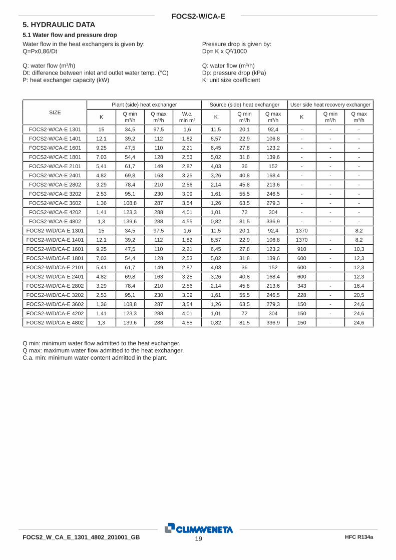
FOCS2_W_CA_E_1301_4802_201001_GB
SIZE
Plant (side) heat exchanger Source (side) heat exchanger User side heat recovery exchanger
KQ minm3/h
Q maxm3/h
W.c.min m3 K
Q minm3/h
Q maxm3/h
KQ minm3/h
Q maxm3/h
FOCS2-W/CA-E 1301 15 34,5 97,5 1,6 11,5 20,1 92,4 - - -
FOCS2-W/CA-E 1401 12,1 39,2 112 1,82 8,57 22,9 106,8 - - -
FOCS2-W/CA-E 1601 9,25 47,5 110 2,21 6,45 27,8 123,2 - - -
FOCS2-W/CA-E 1801 7,03 54,4 128 2,53 5,02 31,8 139,6 - - -
FOCS2-W/CA-E 2101 5,41 61,7 149 2,87 4,03 36 152 - - -
FOCS2-W/CA-E 2401 4,82 69,8 163 3,25 3,26 40,8 168,4 - - -
FOCS2-W/CA-E 2802 3,29 78,4 210 2,56 2,14 45,8 213,6 - - -
FOCS2-W/CA-E 3202 2,53 95,1 230 3,09 1,61 55,5 246,5 - - -
FOCS2-W/CA-E 3602 1,36 108,8 287 3,54 1,26 63,5 279,3 - - -
FOCS2-W/CA-E 4202 1,41 123,3 288 4,01 1,01 72 304 - - -
FOCS2-W/CA-E 4802 1,3 139,6 288 4,55 0,82 81,5 336,9 - - -
FOCS2-W/D/CA-E 1301 15 34,5 97,5 1,6 11,5 20,1 92,4 1370 - 8,2
FOCS2-W/D/CA-E 1401 12,1 39,2 112 1,82 8,57 22,9 106,8 1370 - 8,2
FOCS2-W/D/CA-E 1601 9,25 47,5 110 2,21 6,45 27,8 123,2 910 - 10,3
FOCS2-W/D/CA-E 1801 7,03 54,4 128 2,53 5,02 31,8 139,6 600 - 12,3
FOCS2-W/D/CA-E 2101 5,41 61,7 149 2,87 4,03 36 152 600 - 12,3
FOCS2-W/D/CA-E 2401 4,82 69,8 163 3,25 3,26 40,8 168,4 600 - 12,3
FOCS2-W/D/CA-E 2802 3,29 78,4 210 2,56 2,14 45,8 213,6 343 - 16,4
FOCS2-W/D/CA-E 3202 2,53 95,1 230 3,09 1,61 55,5 246,5 228 - 20,5
FOCS2-W/D/CA-E 3602 1,36 108,8 287 3,54 1,26 63,5 279,3 150 - 24,6
FOCS2-W/D/CA-E 4202 1,41 123,3 288 4,01 1,01 72 304 150 - 24,6
FOCS2-W/D/CA-E 4802 1,3 139,6 288 4,55 0,82 81,5 336,9 150 - 24,6
Water fl ow in the heat exchangers is given by:Q=Px0,86/Dt
Q: water fl ow (m3/h)Dt: difference between inlet and outlet water temp. (°C)P: heat exchanger capacity (kW)
Pressure drop is given by:Dp= K x Q2/1000
Q: water fl ow (m3/h)Dp: pressure drop (kPa)K: unit size coeffi cient
Q min: minimum water fl ow admitted to the heat exchanger.Q max: maximum water fl ow admitted to the heat exchanger.C.a. min: minimum water content admitted in the plant.
5.1 Water fl ow and pressure drop
5. HYDRAULIC DATA
19
FOCS2-W/CA-E
HFC R134a

FOCS2_W_CA_E_1301_4802_201001_GB
SIZE
Plant (side) heat exchanger Source (side) heat exchanger User side heat recovery exchanger
KQ minm3/h
Q maxm3/h
W.c.min m3 K
Q minm3/h
Q maxm3/h
KQ minm3/h
Q maxm3/h
FOCS2-W/H/CA-E 1301 15 34,5 97,5 11,5 11,5 20,1 92,4 - - -
FOCS2-W/H/CA-E 1401 12,1 39,2 112 8,57 8,57 22,9 106,8 - - -
FOCS2-W/H/CA-E 1601 9,25 47,5 110 6,45 6,45 27,8 123,2 - - -
FOCS2-W/H/CA-E 1801 7,03 54,4 128 5,02 5,02 31,8 139,6 - - -
FOCS2-W/H/CA-E 2101 5,41 61,7 149 4,03 4,03 36 152 - - -
FOCS2-W/H/CA-E 2401 4,82 69,8 163 3,26 3,26 40,8 168,4 - - -
FOCS2-W/H/CA-E 2802 3,29 78,4 210 2,14 2,14 45,8 213,6 - - -
FOCS2-W/H/CA-E 3202 2,53 95,1 230 1,61 1,61 55,5 246,5 - - -
FOCS2-W/H/CA-E 3602 1,36 108,8 287 1,26 1,26 63,5 279,3 - - -
FOCS2-W/H/CA-E 4202 1,41 123,3 288 1,01 1,01 72 304 - - -
FOCS2-W/H/CA-E 4802 1,3 139,6 288 0,82 0,82 81,5 336,9 - - -
FOCS2-W-/R/CA-E 1301 15 34,5 97,5 11,5 11,5 20,1 92,4 11,5 40,2 92,4
FOCS2-W-/R/CA-E 1401 12,1 39,2 112 8,57 8,57 22,9 107 8,57 45,8 107
FOCS2-W-/R/CA-E 1601 9,25 47,5 110 6,45 6,45 27,8 123 6,45 55,6 123
FOCS2-W-/R/CA-E 1801 7,03 54,4 128 5,02 5,02 31,8 140 5,02 63,6 140
FOCS2-W-/R/CA-E 2802 3,29 78,4 210 2,14 2,14 45,8 214 2,14 91,6 214
FOCS2-W-/R/CA-E 3202 2,53 95,1 230 1,61 1,61 55,5 247 1,61 111 247
FOCS2-W-/R/CA-E 3602 1,36 109 287 1,26 1,26 63,5 279 1,26 127 279
Q min: minimum water fl ow admitted to the heat exchanger.Q max: maximum water fl ow admitted to the heat exchanger.C.a. min: minimum water content admitted in the plant.
20
FOCS2-W/CA-E
HFC R134a
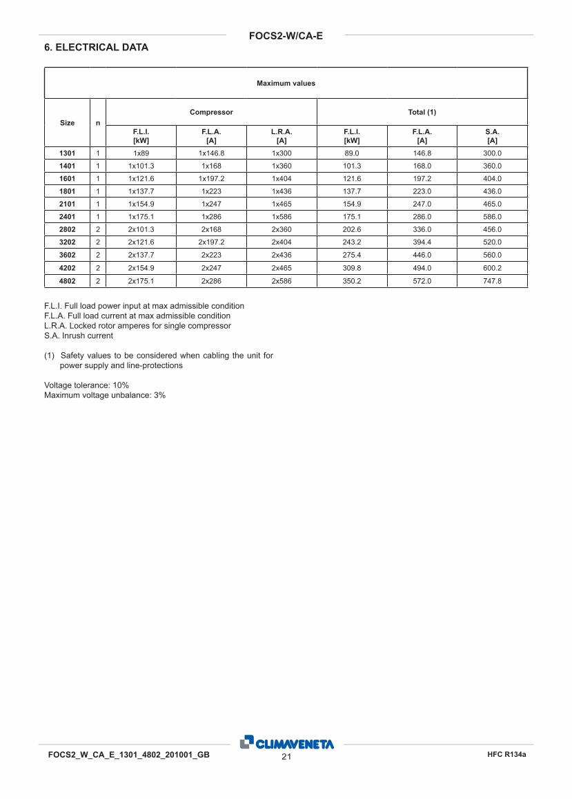
6. ELECTRICAL DATA
Maximum values
Size nCompressor Total (1)
F.L.I. [kW]
F.L.A. [A]
L.R.A. [A]
F.L.I. [kW]
F.L.A. [A]
S.A.[A]
1301 1 1x89 1x146.8 1x300 89.0 146.8 300.0
1401 1 1x101.3 1x168 1x360 101.3 168.0 360.0
1601 1 1x121.6 1x197.2 1x404 121.6 197.2 404.0
1801 1 1x137.7 1x223 1x436 137.7 223.0 436.0
2101 1 1x154.9 1x247 1x465 154.9 247.0 465.0
2401 1 1x175.1 1x286 1x586 175.1 286.0 586.0
2802 2 2x101.3 2x168 2x360 202.6 336.0 456.0
3202 2 2x121.6 2x197.2 2x404 243.2 394.4 520.0
3602 2 2x137.7 2x223 2x436 275.4 446.0 560.0
4202 2 2x154.9 2x247 2x465 309.8 494.0 600.2
4802 2 2x175.1 2x286 2x586 350.2 572.0 747.8
F.L.I. Full load power input at max admissible conditionF.L.A. Full load current at max admissible conditionL.R.A. Locked rotor amperes for single compressorS.A. Inrush current
(1) Safety values to be considered when cabling the unit for power supply and line-protections
Voltage tolerance: 10%Maximum voltage unbalance: 3%
21FOCS2_W_CA_E_1301_4802_201001_GB
FOCS2-W/CA-E
HFC R134a

CA-EFOCS2-W7.0 FULL LOAD SOUND LEVEL
SIZE Octave band [Hz] 20001000 500 250 125 63 80004000
Total sound level
Sound power level dB(A)
SOUND POWER
81 78 89 93 96 84 73 67 971301 81 78 89 93 96 84 73 67 971401 81 78 89 93 96 84 73 67 971601 81 78 89 93 96 84 73 67 971801 81 78 89 93 96 84 73 67 972101 81 78 89 93 96 84 73 67 972401 83 80 90 95 98 86 75 69 992802 83 80 90 95 98 86 75 69 993202 83 80 90 95 98 86 75 69 993602 83 80 90 95 98 86 75 69 994202 83 80 90 95 98 86 75 69 994802
Plant (side) cooling exchanger water (in/out) 12/7 °CSource (side) heat exchanger water (in/out) 30/35 °C Sound power on the basis of measurements made in compliance with ISO 9614 and Eurovent 8/1 for Eurovent certified units; in compliance with ISO 3744 for non-certified units Such certification refers specifically to the sound Power Level in dB(A). This is therefore the only acoustic data to be considered as binding.
Working conditions
SIZE Octave band [Hz] at 10 m
20001000 500 250 125 63 80004000Total sound
level Sound pressure level dB(A)
SOUND PRESSURE LEVEL
49 46 57 61 64 52 41 35 651301 49 46 57 61 64 52 41 35 651401 49 46 57 61 64 52 41 35 651601 49 46 57 61 64 52 41 35 651801 49 46 57 61 64 52 41 35 652101 49 46 57 61 64 52 41 35 652401 51 48 58 63 66 54 43 37 672802 51 48 58 63 66 54 43 37 673202 51 48 58 63 66 54 43 37 673602 51 48 58 63 66 54 43 37 674202 51 48 58 63 66 54 43 37 674802
Plant (side) cooling exchanger water (in/out) 12/7 °CSource (side) heat exchanger water (in/out) 30/35 °C Average sound pressure level, at 10 (m.) distance, unit in a free field on a reflective surface; non-binding value obtained from the sound power level. Additional soundproofing The sound power and pressure levels are reduced of 12 dB(A) when present the accessory “integral acoustical enclosure basic”and of 16 dB(A) when present the accessory “integral acoustical enclosure plus”.
Working conditions
22ELCADOC - Ver. 0.9.9.17 FOCS2_W_CA_E_1301_4802_201001_GB Ref.: R134a

FOCS2-W/CA-E
A1 HFC R134aFOCS2_W_CA_E_1301_4802_201001_GB
For installation purposes, please refer to the documentation sent after the pur-chase contract. These technical data should be considered as indicative.
CLIMAVENETA may modify them at any moment.NOTE:
Lifting bar
H
B
A
R4 R3
R1
R2
EVAPORATOR WATER INLET
EVAPORATOR WATER OUTLET
CONDENSER WATER INLET
CONDENSER WATER OUTLET
LIFTING POINTS
MAIN ISOLATOR
POWER INLET
8. DIMENSIONAL DRAWINGS

FOCS2-W/CA-E
A2 HFC R134aFOCS2_W_CA_E_1301_4802_201001_GB
For installation purposes, please refer to the documentation sent after the pur-chase contract. These technical data should be considered as indicative.
CLIMAVENETA may modify them at any moment.NOTE:
R3R3R3
R1
R2
R4
H
B
A
Lifting bar
EVAPORATOR WATER INLET
EVAPORATOR WATER OUTLET
CONDENSER WATER INLET
CONDENSER WATER OUTLET
LIFTING POINTS
MAIN ISOLATOR
POWER INLET

FOCS2-W/CA-E
A3 HFC R134a
FOCS2_W_CA_E_1301_4802_201001_GB
Size
DIMENSIONS AND WEIGHTS CLEARANCES (see following page)FOCS2-W/CA-E
A [mm]
B [mm]
H [mm]
P [kg]R1
[mm]R2
[mm]R3
[mm]R4
[mm]
1301 4300 900 1950 2460 900 900 1500 3250
1401 4300 900 1950 2750 900 900 1500 3000
1601 4000 900 2000 3560 900 900 1500 3250
1801 4000 900 2000 3720 900 900 1500 3500
2101 4000 900 2000 3760 900 900 1500 3500
2401 4300 900 2100 4180 900 900 1500 3000
2802 4600 1150 2195 5360 900 900 1500 3000
3202 4950 1150 2195 6410 900 900 1500 2750
3602 5220 1150 2195 6870 900 900 1500 2750
4202 4920 1150 2350 7850 900 900 1500 2750
4802 4920 1285 2430 8470 900 900 1500 2750
Size
DIMENSIONS AND WEIGHTS CLEARANCES (see following page)FOCS2-W/D/CA-E
A [mm]
B [mm]
H [mm]
P [kg]R1
[mm]R2
[mm]R3
[mm]R4
[mm]
1301 4300 900 1950 2650 900 900 1500 3000
1401 4300 900 1950 2770 900 900 1500 3000
1601 4000 900 2000 3590 900 900 1500 3250
1801 4000 900 2000 3750 900 900 1500 3500
2101 4000 900 2000 3790 900 900 1500 3500
2401 4300 900 2100 4210 900 900 1500 3000
2802 4600 1150 2195 5390 900 900 1500 3000
3202 4950 1150 2195 6470 900 900 1500 2750
3602 5220 1150 2195 6930 900 900 1500 2750
4202 4920 1285 2430 8500 900 900 1500 2750
4802 4920 1285 2430 8530 900 900 1500 2750
Size
DIMENSIONS AND WEIGHTS CLEARANCES (see following page)FOCS2-W/H/CA-E
A [mm]
B [mm]
H [mm]
P [kg]R1
[mm]R2
[mm]R3
[mm]R4
[mm]
1301 4300 900 1950 2460 900 900 1500 3000
1401 4300 900 1950 2750 900 900 1500 3000
1601 4000 900 2000 3560 900 900 1500 3250
1801 4000 900 2000 3720 900 900 1500 3500
2101 4000 900 2000 3760 900 900 1500 3500
2401 4300 900 2100 4180 900 900 1500 3000
2802 4600 1150 2195 5360 900 900 1500 3000
3202 4950 1150 2195 6410 900 900 1500 2750
3602 5220 1150 2195 6870 900 900 1500 2750
4202 4920 1150 2350 7850 900 900 1500 2750
4802 4920 1285 2430 8470 900 900 1500 2750
Size
DIMENSIONS AND WEIGHTS CLEARANCES (see following page)FOCS2-W/R/CA-E
A [mm]
B [mm]
H [mm]
P [kg]R1
[mm]R2
[mm]R3
[mm]R4
[mm]
1301 4000 900 2000 3170 900 900 1500 3250
1401 4000 900 2000 3240 900 900 1500 3250
1601 4000 900 2100 4070 900 900 1500 3250
1801 4000 900 2100 4240 900 900 1500 3500
2802 4600 1285 2300 6340 900 900 1500 3000
3202 4950 1285 2300 7450 900 900 1500 2750
3602 5200 1285 2430 7950 900 900 1500 2750

A4 HFC R134aFOCS2_W_CA_E_1301_4802_201001_GB
FOCS2-W/CA-E
EVAPORATOR CONDENSER
WATER INLET WATER OUTLET WATER INLET WATER OUTLET
ø ø ø ø
1301 FLEXIBLE JOINT 5" FLEXIBLE JOINT 5" FLEXIBLE JOINT 4" FLEXIBLE JOINT 4"
1401 FLEXIBLE JOINT 5" FLEXIBLE JOINT 5" FLEXIBLE JOINT 5" FLEXIBLE JOINT 5"
1601 FLEXIBLE JOINT 6" FLEXIBLE JOINT 6" FLEXIBLE JOINT 5" FLEXIBLE JOINT 5"
1801 FLEXIBLE JOINT 6" FLEXIBLE JOINT 6" FLEXIBLE JOINT 5" FLEXIBLE JOINT 5"
2101 FLEXIBLE JOINT 6" FLEXIBLE JOINT 6" FLEXIBLE JOINT 5" FLEXIBLE JOINT 5"
2401 FLEXIBLE JOINT 6" FLEXIBLE JOINT 6" FLEXIBLE JOINT 6" FLEXIBLE JOINT 6"
2802 FLEXIBLE JOINT 8" FLEXIBLE JOINT 8" FLEXIBLE JOINT 5" FLEXIBLE JOINT 5"
3202 FLEXIBLE JOINT 8" FLEXIBLE JOINT 8" FLEXIBLE JOINT 5" FLEXIBLE JOINT 5"
3602 FLEXIBLE JOINT 8" FLEXIBLE JOINT 8" FLEXIBLE JOINT 5" FLEXIBLE JOINT 5"
4202 FLEXIBLE JOINT 10" FLEXIBLE JOINT 10" FLEXIBLE JOINT 5" FLEXIBLE JOINT 5"
4802 FLEXIBLE JOINT 10" FLEXIBLE JOINT 10" FLEXIBLE JOINT 6" FLEXIBLE JOINT 6"
FOCS2-W/CA-E

A5 HFC R134aFOCS2_W_CA_E_1301_4802_201001_GB
FOCS2-W/D/CA-E
FOCS2-W/D/CA-E
EVAPORATOR CONDENSER RECUPERATOR
WATER INLET WATER OUTLET WATER INLET WATER OUTLET WATER INLET WATER OUTLET
ø ø ø ø ø ø
1301 FLEXIBLE JOINT 5" FLEXIBLE JOINT 5" FLEXIBLE JOINT 4" FLEXIBLE JOINT 4" GAS 1"1/4 GAS 1"1/4
1401 FLEXIBLE JOINT 5" FLEXIBLE JOINT 5" FLEXIBLE JOINT 5" FLEXIBLE JOINT 5" GAS 1"1/4 GAS 1"1/4
1601 FLEXIBLE JOINT 6" FLEXIBLE JOINT 6" FLEXIBLE JOINT 5" FLEXIBLE JOINT 5" GAS 1"1/4 GAS 1"1/4
1801 FLEXIBLE JOINT 6" FLEXIBLE JOINT 6" FLEXIBLE JOINT 5" FLEXIBLE JOINT 5" GAS 1"1/4 GAS 1"1/4
2101 FLEXIBLE JOINT 6" FLEXIBLE JOINT 6" FLEXIBLE JOINT 5" FLEXIBLE JOINT 5" GAS 1"1/4 GAS 1"1/4
2401 FLEXIBLE JOINT 6" FLEXIBLE JOINT 6" FLEXIBLE JOINT 6" FLEXIBLE JOINT 6" GAS 1"1/4 GAS 1"1/4
2802 FLEXIBLE JOINT 8" FLEXIBLE JOINT 8" FLEXIBLE JOINT 5" FLEXIBLE JOINT 5" GAS 1"1/4 GAS 1"1/4
3202 FLEXIBLE JOINT 8" FLEXIBLE JOINT 8" FLEXIBLE JOINT 5" FLEXIBLE JOINT 5" GAS 1"1/4 GAS 1"1/4
3602 FLEXIBLE JOINT 8" FLEXIBLE JOINT 8" FLEXIBLE JOINT 5" FLEXIBLE JOINT 5" GAS 1"1/4 GAS 1"1/4
4202 FLEXIBLE JOINT 10" FLEXIBLE JOINT 10" FLEXIBLE JOINT 5" FLEXIBLE JOINT 5" GAS 1"1/4 GAS 1"1/4
4802 FLEXIBLE JOINT 10" FLEXIBLE JOINT 10" FLEXIBLE JOINT 6" FLEXIBLE JOINT 6" GAS 1"1/4 GAS 1"1/4

A6 HFC R134aFOCS2_W_CA_E_1301_4802_201001_GB
FOCS2-W/H/CA-E
EVAPORATOR CONDENSER
WATER INLET WATER OUTLET WATER INLET WATER OUTLET
ø ø ø ø
1301 FLEXIBLE JOINT 5" FLEXIBLE JOINT 5" FLEXIBLE JOINT 4" FLEXIBLE JOINT 4"
1401 FLEXIBLE JOINT 5" FLEXIBLE JOINT 5" FLEXIBLE JOINT 5" FLEXIBLE JOINT 5"
1601 FLEXIBLE JOINT 6" FLEXIBLE JOINT 6" FLEXIBLE JOINT 5" FLEXIBLE JOINT 5"
1801 FLEXIBLE JOINT 6" FLEXIBLE JOINT 6" FLEXIBLE JOINT 5" FLEXIBLE JOINT 5"
2101 FLEXIBLE JOINT 6" FLEXIBLE JOINT 6" FLEXIBLE JOINT 5" FLEXIBLE JOINT 5"
2401 FLEXIBLE JOINT 6" FLEXIBLE JOINT 6" FLEXIBLE JOINT 6" FLEXIBLE JOINT 6"
2802 FLEXIBLE JOINT 8" FLEXIBLE JOINT 8" FLEXIBLE JOINT 5" FLEXIBLE JOINT 5"
3202 FLEXIBLE JOINT 8" FLEXIBLE JOINT 8" FLEXIBLE JOINT 5" FLEXIBLE JOINT 5"
3602 FLEXIBLE JOINT 8" FLEXIBLE JOINT 8" FLEXIBLE JOINT 5" FLEXIBLE JOINT 5"
4202 FLEXIBLE JOINT 10" FLEXIBLE JOINT 10" FLEXIBLE JOINT 5" FLEXIBLE JOINT 5"
4802 FLEXIBLE JOINT 10" FLEXIBLE JOINT 10" FLEXIBLE JOINT 6" FLEXIBLE JOINT 6"
FOCS2-W/H/CA-E

A7 HFC R134aFOCS2_W_CA_E_1301_4802_201001_GB
FOCS2-W/R/CA-E
EVAPORATOR CONDENSER RECUPERATOR
WATER INLET WATER OUTLET WATER INLET WATER OUTLET WATER INLET WATER OUTLET
ø ø ø ø ø ø
1301 FLEXIBLE JOINT 5" FLEXIBLE JOINT 5" FLEXIBLE JOINT 5" FLEXIBLE JOINT 5" FLEXIBLE JOINT 5" FLEXIBLE JOINT 5"
1401 FLEXIBLE JOINT 5" FLEXIBLE JOINT 5" FLEXIBLE JOINT 5" FLEXIBLE JOINT 5" FLEXIBLE JOINT 5" FLEXIBLE JOINT 5"
1601 FLEXIBLE JOINT 6" FLEXIBLE JOINT 6" FLEXIBLE JOINT 5" FLEXIBLE JOINT 5" FLEXIBLE JOINT 5" FLEXIBLE JOINT 5"
1801 FLEXIBLE JOINT 6" FLEXIBLE JOINT 6" FLEXIBLE JOINT 5" FLEXIBLE JOINT 5" FLEXIBLE JOINT 5" FLEXIBLE JOINT 5"
2802 FLEXIBLE JOINT 8" FLEXIBLE JOINT 8" FLEXIBLE JOINT 5" FLEXIBLE JOINT 5" FLEXIBLE JOINT 5" FLEXIBLE JOINT 5"
3202 FLEXIBLE JOINT 8" FLEXIBLE JOINT 8" FLEXIBLE JOINT 5" FLEXIBLE JOINT 5" FLEXIBLE JOINT 5" FLEXIBLE JOINT 5"
3602 FLEXIBLE JOINT 8" FLEXIBLE JOINT 8" FLEXIBLE JOINT 5" FLEXIBLE JOINT 5" FLEXIBLE JOINT 5" FLEXIBLE JOINT 5"
FOCS2-W/R/CA-E

9. LEGEND OF PIPE CONNECTIONS
UNI ISO 228/1
Pipe threads where pressure-tight joints are not made on the threads - Designation, dimensions and tolerances
Used terminology: G: Pipe threads where pressure-tight joints are not made on the
threadsA: Close tolerance class for external pipe threads where pres-
sure-tight joints are not made on the threadsB: Wider tolerance class for external pipe threads where pres-
sure-tight joints are not made on the threads
Internal threads: G letter followed by thread mark (only toler-ance class)
External threads: G letter followed by thread A letter for A class external threads or by B letter for B class external threads.
UNI ISO 7/1
Pipe threads where pressure-tight joints are made on the threads - Designation, dimensions and tolerances
Used terminology: Rp: Internal cylindrical threads where pressure-tight joints are
made on the threadsRc: Internal conical threads where pressure-tight joints are
made on the threadsR: External conical threads where pressure-tight joints are
made on the threads
Internal cylindrical threads: R letter followed by p letterInternal conical threads: R letter followed by c letterExternal conical threads: R letter
Designation Description
UNI ISO 7/1 - Rp 1 1/2Internal cylindrical threads where pressure-tight joints are made on the threads, defined by stand-ard UNI ISO 7/1 Conventional ø : 1 ½”
UNI ISO 7/1 - Rp 2 1/2Internal cylindrical threads where pressure-tight joints are made on the threads, defined by stand-ard UNI ISO 7/1 Conventional ø : 2 ½”
UNI ISO 7/1 - Rp 3Internal cylindrical threads where pressure-tight joints are made on the threads, defined by stand-ard UNI ISO 7/1 Conventional ø : 3”
UNI ISO 7/1 - R 3External conical threads where pressure-tight joints are made on the threads, defined by standard UNI ISO 7/1Conventional ø : 3”
UNI ISO 228/1 - G 4 B
Pipe threads where pressure-tight joints are not made on the threads, defined by standard UNI ISO 228/1Wide tolerance class for external pipe threadsConventional ø : 4”
DN 80 PN 16 Flange Nominal Diameter: 80 mmNominal Pressure: 16 bar
Note:
Conventional diameter value [in inches] identifies short thread designation, based upon the relative standard.All relative values are defined by standards.As example, here below some values:
UNI ISO 7/1 UNI ISO 228/1conventional ø 1” 1”
Pitch 2.309 mm 2.309 mm
external ø 33.249 mm 33.249 mm
core ø 30.291 mm 30.291 mm
Thread height 1.479 mm 1.479 mm
A8
FOCS2-W/CA-E
HFC R134aFOCS2_W_CA_E_1301_4802_201001_GB

Pressostatic valve with grey cast iron body. It’s used for regulat-ing the flow of water as a function of the condensing pressure, maintaining it constant during operation. When the refrigeration plant is stopped, the cooling water flow is shut off automatically.The valve is selected for a thermic drop of 10°C and tested by Climaveneta during the unit’s test. Recommended for appli-
cations with low temperature water, for example groundwater, where it’s request the condensation pressure’s control and it’s possible to work with variable flow on the rejection circuit.
10. CONDENSATION CONTROL DEVICES
PRESSOSTATIC VALVE
SizeDT 10K
Q cond[m3/h]
Dp[bar]
1301 35.7 0.63
1401 40.2 0.83
1601 46.9 1.18
1801 53.8 0.47
2101 60.5 0.61
2401 66.3 0.75
2802 80.4 0.83
3202 93.8 1.18
3602 107.6 0.47
4202 120.9 0.61
4802 132.7 0.76
B1
FOCS2-W/CA-E
HFC R134aFOCS2_W_CA_E_1301_4802_201001_GB
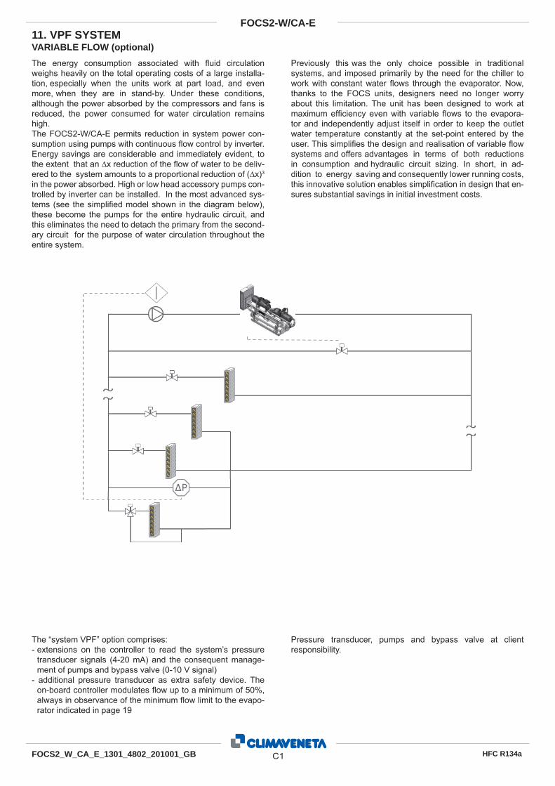
VARIABLE FLOW (optional)
The energy consumption associated with fl uid circulation weighs heavily on the total operating costs of a large installa-tion, especially when the units work at part load, and even more, when they are in stand-by. Under these conditions, although the power absorbed by the compressors and fans is reduced, the power consumed for water circulation remains high.The FOCS2-W/CA-E permits reduction in system power con-sumption using pumps with continuous fl ow control by inverter. Energy savings are considerable and immediately evident, to the extent that an ∆x reduction of the fl ow of water to be deliv-ered to the system amounts to a proportional reduction of (∆x)3 in the power absorbed. High or low head accessory pumps con-trolled by inverter can be installed. In the most advanced sys-tems (see the simplifi ed model shown in the diagram below), these become the pumps for the entire hydraulic circuit, and this eliminates the need to detach the primary from the second-ary circuit for the purpose of water circulation throughout the entire system.
Previously this was the only choice possible in traditional systems, and imposed primarily by the need for the chiller to work with constant water fl ows through the evaporator. Now, thanks to the FOCS units, designers need no longer worry about this limitation. The unit has been designed to work at maximum effi ciency even with variable fl ows to the evapora-tor and independently adjust itself in order to keep the outlet water temperature constantly at the set-point entered by the user. This simplifi es the design and realisation of variable fl ow systems and offers advantages in terms of both reductions in consumption and hydraulic circuit sizing. In short, in ad-dition to energy saving and consequently lower running costs, this innovative solution enables simplifi cation in design that en-sures substantial savings in initial investment costs.
The “system VPF” option comprises: - extensions on the controller to read the system’s pressure
transducer signals (4-20 mA) and the consequent manage-ment of pumps and bypass valve (0-10 V signal)
- additional pressure transducer as extra safety device. The on-board controller modulates fl ow up to a minimum of 50%, always in observance of the minimum fl ow limit to the evapo-rator indicated in page 19
Pressure transducer, pumps and bypass valve at client responsibility.
11. VPF SYSTEM
C1
FOCS2-W/CA-E
HFC R134aFOCS2_W_CA_E_1301_4802_201001_GB
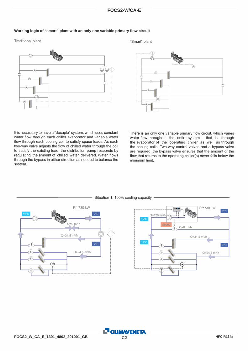
Working logic of “smart” plant with an only one variable primary fl ow circuit
Traditional plant “Smart” plant
It is necessary to have a “decuple” system, which uses constant water fl ow through each chiller evaporator and variable water fl ow through each cooling coil to satisfy space loads. As each two-way valve adjusts the fl ow of chilled water through the coil to satisfy the existing load, the distribution pump responds by regulating the amount of chilled water delivered. Water fl ows through the bypass in either direction as needed to balance the system.
There is an only one variable primary fl ow circuit, which varies water fl ow throughout the entire system – that is, through the evaporator of the operating chiller as well as through the cooling coils. Two-way control valves and a bypass valve are required; the bypass valve ensures that the amount of the fl ow that returns to the operating chiller(s) never falls below the minimum limit.
Situation 1. 100% cooling capacity
ΔpΔp
Pf=730 kW
3/h
Q=31.5 m3/h
Q=94.5 m3/h
7°C
7°C
12°C
Q=0 m
ΔpΔp
Pf=730 kW
Q=0 m3/h
Q=31.5 m3/h
Q=94.5 m3/h
7°C
7°C12°C
12°CQ=126 m3/h
closed
C2
FOCS2-W/CA-E
HFC R134aFOCS2_W_CA_E_1301_4802_201001_GB
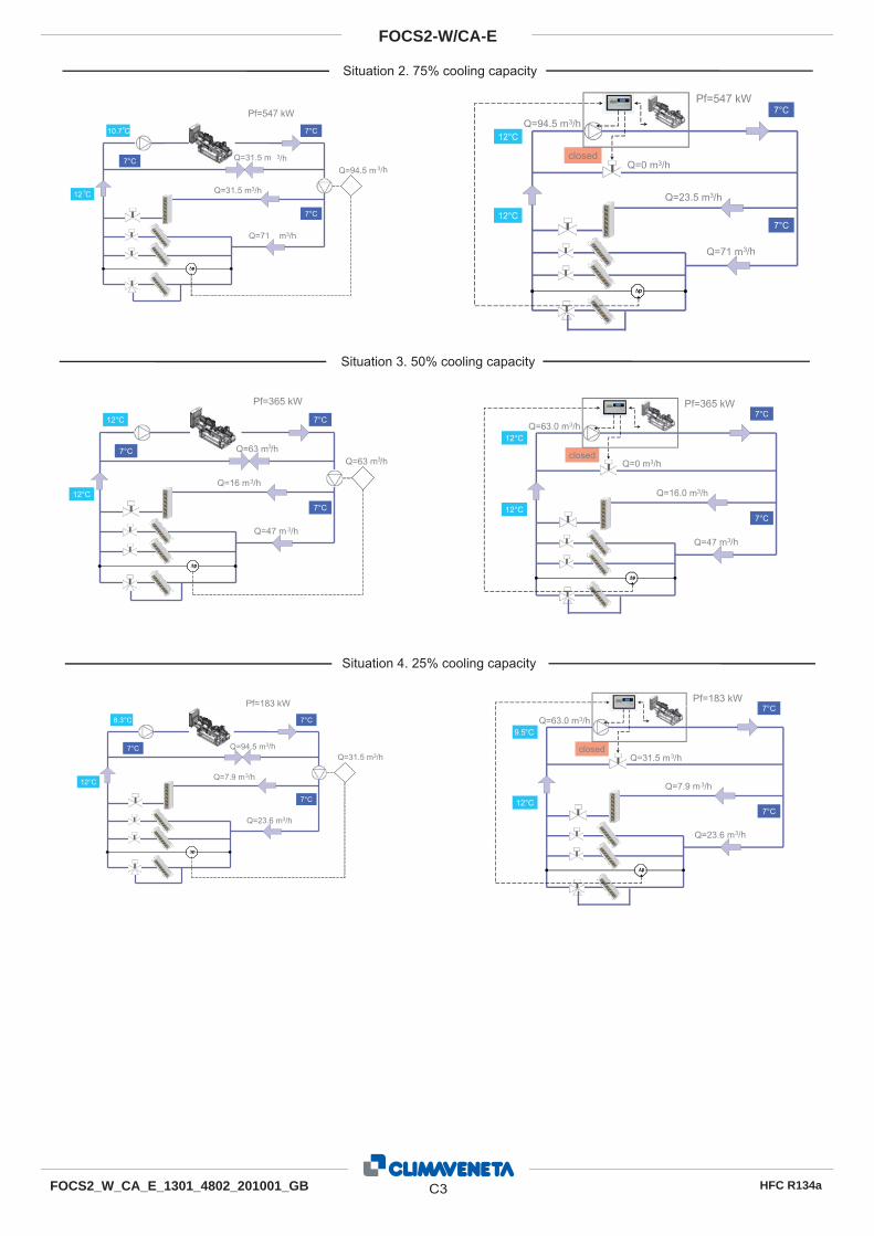
Situation 2. 75% cooling capacity
Situation 3. 50% cooling capacity
Situation 4. 25% cooling capacity
ΔpΔp
Pf=547 kW
3/h
Q=31.5 m3/h
Q=71 m3/h
7°C
7°C
10.7°C
Q=31.5 m7°C3/hQ=94.5 m
12°C
ΔpΔp
Pf=547 kW
Q=0 m3/h
Q=23.5 m3/h
Q=71 m3/h
7°C
7°C12°C
12°CQ=94.5 m3/h
closed
ΔpΔp
Pf=365 kW
3/h
Q=16 m3/h
Q=47 m 3/h
7°C
7°C
12°C
Q=63 m
12°C
7°C3/hQ=63 m
ΔpΔp
Pf=365 kW
Q=0 m3/h
Q=16.0 m3/h
Q=47 m3/h
7°C
7°C12°C
12°CQ=63.0 m3/h
closed
ΔpΔp
Pf=183 kW
3/h
Q=7.9 m3/h
Q=23.6 m3/h
7°C
7°C
8.3°C
Q=94.5 m7°C
12°C
Q=31.5 m3/h
ΔpΔp
Pf=183 kW
Q=31.5 m3/h
Q=7.9 m3/h
Q=23.6 m3/h
7°C
7°C12°C
9.5°CQ=63.0 m3/h
closed
C3
FOCS2-W/CA-E
HFC R134aFOCS2_W_CA_E_1301_4802_201001_GB

www.climaveneta.com
Climaveneta S.p.A.Via Sarson 57/c36061 Bassano del Grappa (VI)ItalyTel +39 0424 509 500Fax +39 0424 509 [email protected]
Climaveneta Home System Via Duca d’Aosta 12131030 Mignagola (TV)ItalyTel +39 0422 4131Fax +39 0422 [email protected]
Climaveneta France3, Village d’EntreprisesZA de la Couronne des PrésAvenue de la Mauldre78680 EpôneFranceTel +33 (0)1 30 95 19 19Fax +33 (0)1 30 95 18 [email protected]
Climaveneta DeutschlandRhenus Platz 259439 HolzwickedeGermanyTel +49 2301 91222-0Fax +49 2301 [email protected]
Climaveneta España - Top ClimaLondres 67, 1 4 08036 BarcelonaSpainTel +34 934 195 600Fax +34 934 195 [email protected]
Climaveneta Chat Union Refrig. Equipment Co Ltd88 Bai Yun Rd, Pudong XinghuoNew dev. zone 201419 ShanghaiChinaTel 008 621 575 055 66Fax 008 621 575 057 97
Climaveneta Polska Sp. z o.o.Ul. Sienkiewicza 13A,05-120 Legionowo,PolandTel +48 22 766 34 55-57Fax +48 22 784 39 [email protected]