foam insulation behavior in void space under fire conditions
TRANSCRIPT

FOAM INSULATION BEHAVIOR IN VOID SPACE UNDER FIRE CONDITIONS
Andrew KurzawskiDepartment of Mechanical Engineering
University of Texas at AustinAustin, TX 78712
Email: [email protected]
Ofodike A. Ezekoye∗Department of Mechanical Engineering
The University of Texas at AustinAustin, TX 78712
Email: [email protected]
ABSTRACTA fire contained within a room can spread into void spaces
in the walls and ceiling through penetrations in the material thatlines the compartment. Few studies have looked at how a roomand contents fire transitions to a structural fire. One of the activeareas of fire research is the coupling of the fire to the structure.Lightweight wood frame construction represents the majority ofresidential construction in the U.S. The construction details andchoice of materials will affect the overall fire resistance of thestructure. Because of the relative lack of knowledge on the firepenetration into wall spaces, this research examined how firemight penetrate into the void spaces of wood framed structures.
In the U.S.A., a critical barrier to the penetration of hotgas products into void spaces is provided by the gypsum-boardskin of the compartment. For most compartments, there aremany penetrations within the compartment’s gypsum-board skin.Common potential access points include security system wiring(e.q. smoke detectors and cameras), ventilation fixtures, lightswitches, and electrical outlets among others. A hole in the gyp-sum may create opportunities for void space ignition. One ofthe purposes of this work is to develop a small scale testing sys-tem to characterize fire driven flow and heat transfer into a voidspace. With such an apparatus, one can rapidly identify materi-als that are prone to igniting for a given leakage geometry andfire size. Common materials found in void spaces include woodenstructural members, plywood/oriented strand board, a variety ofinsulation types, and vapor barriers. This study discusses thecharacteristics of the small scale experimental system and pre-liminary tests on a range of void space construction materials.
∗Address all correspondence to this author.
NOMENCLATUREMLC Mass Loss Calorimeter.EPS Expanded Polystyrene.XPS Extruded Polystyrene.PIR Polyisocyanurate.PUR Polyurethane.OSB Oriented Strand Board.AAC Autoclaved Aerated Concrete.FR Flame Retardant.NFR Non-Flame Retardant.
INTRODUCTIONA fire contained within a room can spread into void spaces
in the walls and ceiling through penetrations in the material thatlines the compartment. This can be problematic for firefightersconducting overhaul operations because a fire located within thevoid space can be difficult to detect and failure to do so can resultin fire spread through the void spaces to other rooms within thestructure.
Few studies have examined fire dynamics withinvoid/concealed spaces. Tan et al. [1] conducted experi-ments to study flame spread along cables located within a voidspace. Other experiments done by Tanaka et al. [2] focused onsmoke transport in the shafts and void spaces of large structures.Examination of National Fire Incident Reporting System datashows that 5% of residential fires began in a concealed space(attic assembly or wall) between 2007 and 2011 [3]. However,there are no known studies on fire penetration into the voidspaces of residential structures, a majority of which in the U.S.
Proceedings of the ASME 2014 International Mechanical Engineering Congress and Exposition IMECE2014
November 14-20, 2014, Montreal, Quebec, Canada
IMECE2014-38849
1 Copyright © 2014 by ASME

are made of lightweight wood frame assemblies. Because ofthe relative lack of knowledge on the fire penetration into voidspaces, this research examined how fire might penetrate into thevoid spaces of wood framed structures.
Balloon frame construction poses the greatest risk for astructure fire to transition into the void space. Mittendorf [4] re-ported that platform construction effectively began in the 1950s.Prior to that, balloon frame construction was used in a significantfraction of residential structures. In balloon frame construction,there sometimes is no inherent fire stopping mechanism inhibit-ing the spread of fire between floors.
In the U.S.A., a critical barrier to the penetration of hotgas products into void spaces is provided by the gypsum-boardskin of the compartment. For most compartments, there aremany penetrations within the compartment’s gypsum-board skin.Common potential access points include security system wiring(e.q. smoke detectors and cameras), ventilation fixtures, lightswitches, and electrical outlets among others (Fig. 1). A holein the gypsum may create opportunities for void space ignition.One of the purposes of this work is to identify materials thatare prone to igniting for a given leakage geometry and fire size.Common materials found in void spaces include wooden struc-tural members, plywood/oriented strand board, a variety of insu-lation types, and vapor barriers.
Smoke DetectorVentilation
Electrical Outlet
Light Switch
FIGURE 1. POTENTIAL ACCESS POINTS FOR HOT GAS TOENTER THE VOID SPACE ON A STANDARD WALL.
Motivation for investigating fire penetrations into voidspaces on a reduced scale came from a series of compartmentscale experiments. An experimental room was outfitted withrepresentative leakages located in a test section that contains avoid space. Figure 2 shows two leakages; a square hole at mid-
compartment height representative of an electrical outlet or lightswitch panel and a smaller rectangular slot ceiling height rep-resentative of a hole cut out to provide wiring access for devicessuch as smoke detectors or security systems. Ignition events wereobserved in the wooden components at higher elevations in thetest section during these experiments whereas the fiberglass in-sulation in the assembly melted upon heating.
FIGURE 2. TEST SECTION WITH LEAKAGES HIGHLIGHTEDBY RED CIRCLES.
A large percentage of the space in residential constructionwalls is occupied by insulation materials. Common types of in-sulation include foams, cellulose, fiberglass, and mineral wool.Fiberglass and mineral wool are generally quoted by manufac-tures to have maximum operating temperatures of around 500oCand 1000oC respectively, above which the material breaks downand melts. Cellulose and foam insulations are produced withflame retardant (FR) additives, with the most common being bo-rax/boric acid for cellulose and mixtures of halogens (Bromineand Chlorine) and/or phosphorus for foam materials. Borax canreduce flame spread but it abets smoldering while boric acid sup-presses glowing and contributes to the formation of a protectivechar layer [5]. Halogen flame retardants operate by trapping freeradicals produced during combustion which disrupts the flamesheet. Phosphorus acts by producing a char layer that inhibitsvolatiles from escaping the material [6] [7].
Given the development of a small-scale apparatus, this workexamined the behavior of foam insulation materials with andwithout flame retardants when exposed to experimental condi-
2 Copyright © 2014 by ASME

tions that simulate hot gas penetration into the void space. Weused observations from a series of room-scale experiments tomotivate the creation of an apparatus that can test hot gas pen-etration localized to the leakage scale. To further examine insu-lation behavior, we tested materials in a radiant heating device atheat fluxes similar to those found in the leakage scale system.
MOTIVATIONPreviously, experiments were conducted in a structure con-
sisting of a single room and an entrance hallway. The tempera-tures and pressures observed in these experiments were used toinform the experimental conditions for the two small-scale sys-tems presented in this work.
The ceiling of the compartment was 2.44 m in height every-where except within the void space, which was 3.05 m tall andopen at the top. The experimental structure was 6.1 m in length,4.88 m wide. In these experiments, the void space was designedto resemble structural void spaces in balloon frame construction,which represents a worst-case structural failure system for a pres-surized fire compartment. The gypsum failure areas were placedthrough the interior gypsum wallboard of the void space to ex-pose the void space to the main room. Fiberglass insulation wasinserted in the void spaces between the studs to more realisticallymodel a typical wall assembly.
Two 30 cm by 30 cm sand burners fueled with propane wereused as the burner system for the compartment. The sand burnerdesign was based on ASTM E 2257, a standard for room firetests [8]. For all room-scale experiments, the fire burned in aninitially closed compartment for approximately 5 minutes be-fore the compartment was ventilated. In the experiments, thecompartment was ventilated by opening a door and window andallowing natural ventilation to occur. Instrumentation included32 thermocouples to measure temperature at four elevations overeight spatial locations. Thermocouple trees are fixed at eight dis-tinct spatial locations. Figure 3 shows the location of each ofthe thermocouple trees as well as the location for the burners andvoid space.
The computational fluid dynamics model, Fire DynamicsSimulator (FDS) version 6.0 (SVN revision 13186), was usedin this study to model the compartment and characterize the ther-mal and flow conditions in the structure. The instruments in theFDS scenario matched the instrumentation in the experiments,and additional nine pressure sensors were located 0.25 m awayfrom the gypsum failure area (GFA) and were used to measurethe pressure over the height of the compartment during variousventilation scenarios. The pressure sensors were located betweenthe two burners at heights of 0.3 m, 0.6 m, 0.9 m, 1.2 m, 1.5 m,1.8 m, 2.1 m, and 2.3 m.
Temperature measurements from two experimental cases areshown in Figure 4 at various elevations within the compartmentfor several thermocouple trees. Thermal stratification is clearly
6.1 m
4.88 m
Door
Void space andgypsum failure area
x
x
x
x
x
x
x
x
Burner
Thermocouple treex
Vent
Top view
FIGURE 3. PLAN VIEW OF THE COMPARTMENT SHOWINGBURNER, THERMOCOUPLE, VENT, AND VOID SPACE LOCA-TIONS.
seen for both cases before and after ventilation. Figure 4 (top)shows the interior compartment temperatures for 150 kW fireconditions. Figure 4 (bottom) shows that the same types of tem-perature profiles exist for a 400 kW fire. These temperatures cor-respond to a thermocouple tree located in the center of the fireroom. Note that the peak temperatures at the highest elevationsof the fire room reach 300 C for the 400 kW fire test.
Computational model predictions of the temperature fieldagreed reasonably well with experimental observations. We wereunable to generate detailed pressure profiles through the experi-ments and thus rely on the computational fluid dynamics for pres-sure versus elevation predictions. The resulting pressure profilesas a function of time are shown in 5. The pressure rise near theceiling is about 7 Pa at 200 s after which the compartment firebecomes under-ventilated. After ventilation occurs, the ceilingpressure becomes steady between 5 Pa to 6 Pa. A hydrostaticpressure difference is present that varies with elevation whichwould create different flow directions across a void dependingon the void elevation.
A large leakage path was placed into the wall void space tohave a well-controlled failure region on the gypsum wall of thecompartment. There was no fire penetration into the wall at the1.2 m elevation. The lack of interior damage under these mid-height outlet conditions led us to consider higher elevation fail-ure. Our hypothesis was that if the gases entering the wall voidare sufficiently hot at higher elevations, then these gases mightinduce smoldering reactions within the void. It was anticipatedthat once the flammable mass inside the wall ignites in a smol-dering reaction (where low oxygen combustion can occur) thissmoldering process could persist over relative long time dura-tions without flaming.
We identified high elevation electrical penetrations (Fig. 1)as potential paths for hot fire gases to ignite materials within voidspaces. A small failure area of less than 1 cm by 2 cm was located
3 Copyright © 2014 by ASME

Vents opened
Vents opened
FIGURE 4. NATURAL VENTILATION TEMPERATURE PRO-FILES FOR 150 kW (TOP) AND 400 kW (BOTTOM) FIRE CASES.
0 100 200 300 400 500 600 700 800 900Time (s)
10
5
0
5
10
15
Pres
sure
(Pa)
2.2 m2.1 m1.8 m1.5 m1.2 m0.9 m0.6 m0.3 m
FIGURE 5. PRESSURE PROFILES FOR NATURAL VENTILA-TION.
behind a smoke detector to simulate a conduit through whichwires might pass. Often, the smoke detector would fall off the
wall during the testing exposing the failure area.Wood elements were placed behind the smoke alarm loca-
tion to simulate typical wooden fixtures such as studs and othermounting surfaces in the void spaces. Fiberglass insulation wasalso placed in the void space adjacent to the wood panel to simu-late typical thermal insulation that might be found in void spaces.Figure 6 shows the wood panel following fire in the compartmentand also the temperature history measured by two thermocouplesin the void near the wooden fixture. Note that the wooden panelhas burned away and that the thermocouples appear to recordan ignition event. Upon heating the fiberglass insulation melted.The impact of the flammability properties of the wall insulatingmaterial will have an effect on the transition to flaming in thewall/void space.
FIGURE 6. (a) POST-FIRE DAMAGE TO WOOD PANEL IN VOIDSPACE BEHIND SMOKE DETECTOR ACCESS HOLE AND (b)THERMOCOUPLE TEMPERATURES BEHIND SMOKE DETEC-TOR IN VOID SPACE.
EXPERIMENTAL SET-UPA selection of materials were tested in two reduced-scale
experimental systems: the void space system and a mass losscalorimeter (MLC). In each system we examined the behavior
4 Copyright © 2014 by ASME

of the materials through qualitative observations and mass lossmeasurements to gain insight into how the materials would re-spond in a full-scale scenario.
Void Space SystemTo better understand ignition within the void space, an ex-
perimental system was constructed to reproduce the thermal en-vironment of a compartment-scale fire localized to the regionwhere a leakage in the compartment wall is present (Fig. 7). Thesystem was designed such that a range of conditions could bereplicated with the focus on the thermal and pressure conditionsin the room-scale fire during a 400 kW fire for a leakage in thecompartment wall at ceiling height. This translates to a gas tem-perature of 300-400oC and gage pressure of ∼5 Pa. The designin this work is an improvement on a previous design detailed byKurzawski [9] which focused on characterizing the system andtesting oriented strand board (OSB) ignition at higher gas tem-peratures.
GasInletFlowMeter
AirInletFlowMeter
Bunsen Burner
In Box TCs Outlet TC
PressureTap
Sample
FIGURE 7. FULL VOID SPACE SYSTEM EXPERIMENTAL SETUP.
A box with one open wall was constructed from autoclavedaerated concrete (AAC) and secured by high temperature mortarand angle iron. The removable leakage wall was made of 1.6cm thick gypsum board with a 1.27 cm diameter hole locatedin the center (10 cm from the interior floor of the box). Theleakage wall is slid into place after ignition of the heat sourceand clamped to reduce leakage around the seam between the walland AAC box which forces hot gases out of the leakage hole. Thebox was heated by a Bunsen Burner with natural gas as the fuel.A flow meter with a range of 1 to 11 standard cubic feet per hour(scfh) air and accuracy ±%4 full scale was used on the naturalgas line. As per the manufacture specifications (King InstrumentCompany), a factor of 1.34 was used to convert the flow rate fromair to standard cubic feet per hour of natural gas. The collar of
the Bunsen burner was marked evenly at four locations to trackthe air flow in quarter turn increments and assure that the samefuel to air ratio is used in each test.
The locations of the three in-box thermocouples were 5.0,10.0, and 15.0 cm from the floor of the box. A pressure tap wasconstructed out of a copper tube joined to a pressure transducer(Setra Model 264) via quarter inch plastic tubing. This was in-serted through the center of the instrument wall level with the10 cm thermocouple and secured with drywall putty. Adjacentto the instrument wall is the removable leakage wall. A fourththermocouple was placed at the leakage outlet and secured to theoutside of the leakage wall with the bead centered in the outletstream.
The air inlet consisted of a copper tube and stainless steeldiffuser attached to a pressurized air supply. The diffuser is lo-cated on the floor of the box 7.5 cm from the Bunsen Burner.The flow was controlled by a flow meter with a range of 0.4 to4.0 standard cubic feet per minute (scfm) and accuracy±%6 fullscale was connected to the air inlet. The air was turned on afterlighting the Bunsen burner and before closing the box with theleakage wall.
Sample holders were constructed out of gypsum and drywallputty to hold 10 cm by 10 cm samples. The sample holder wasnot attached to the box so that it could be placed on the platformafter the outlet gas reached the desired temperature and removedeasily when testing was complete.
This experimental system allows us to vary six input param-eters to test for the thermal conditions and time to ignition of amaterial. These parameters are the air inlet flow rate, Bunsenburner natural gas flow rate, burner air inlet position, leakagehole diameter, target distance from the leakage outlet, and thetarget material.
Through a series of scoping tests where the air flow rate,natural gas flow rate, and burner air position were varied, inputparameters were chosen for the experiments that produced sim-ilar conditions to those observed in the room-scale test. It wasfound that 0.6 scfm air flow rate, 6.5 scfh gas flow rate, and 1.75turns for the burner air inlet produce outlet temperature in therange of 300-400oC and a gage pressure of ∼5 Pa. It was de-termined that the sample in the target holder would be appliedwhen the outlet temperature reached 300oC. Over the course ofeach test the outlet temperature would rise steadily. The distancefrom the leakage outlet to the target material was set at 1 cm.
Mass Loss CalorimeterThe mass loss calorimeter (MLC) was designed for getting
mass loss under a specified heating condition. The heat was sup-plied by a conical heater that is regulated by a temperature con-troller set to provide a specific heating condition. In this case,the heater was held at a constant temperature for each test. Thesamples were positioned on a load cell to measure the mass lost
5 Copyright © 2014 by ASME

due to heating. A full view of the MLC is shown in Figure 8.
CoilThermocouples
Heat Shield
707
975Sample Holder
Heating CoilHousing
Load Cell
TemperatureController
PowerRelay
To PowerOutlet
To Computer
FIGURE 8. FULL MLC EXPERIMENTAL SET UP.
The conical heater was an Iconel heating element with amaximum safe operating temperature of 800oC. The heat shield-ing consisted of two primary parts: the outer shield and the in-ner shield. The outer shield was a strip of sheet metal that wasformed into a hoop while the inner shield was designed to forma cone that fits with the back of the heating element. The heatshielding for the conical heater was made from 0.737 cm thickstainless steel and ceramic fiber insulation was packed into thevoid between the inner and outer shielding.
The heater temperature was maintained by a PID tempera-ture controller (Omega Engineering, a model CN8241). Threethermocouples touching the heater coil monitor the temperatureand feed the signal to the temperature controller which sends asignal to a power relay to control the power supplied to the heater.
Mass loss was measured by a load cell (HBM 1-FIT1/1SB31/20KG) that has a weight capacity of 20 kilograms,a standard RS-485 interface, and a C3 accuracy class. The sam-ple holder was attached to the load cell by a metal rod that runsthrough a calcium silicate heat shield that protects the load cell.The sample holder is designed to snugly hold a 10 cm by 10cm sample. Another half inch thick piece of calcium silicateboard was used to protect the sample from being preheated. Thecalcium silicate board has a maximum allowable temperature of930oC, which is above the maximum safe heater temperature.The heat shield for the sample was mounted on two stainless steelslides below the opening of the heater. This allows the operatorto slide the preheating shielding away from the heater openingwhen the experiment is ready to be run.
To match the heat fluxes seen in the void space system, thetemperature controller was set at 975oC. To get this set point, wefirst estimated the initial heat flux of a 300oC (Tjet ) jet impinging
on a cold (Ts=25oC) sample. Review of the literature found noheat transfer coefficient correlations for the flow regime in thisgeometry, so hc was estimated to be between 50 and 75 W/m2Kby extrapolating from correlations by Wen and Jang [10].
q′′conv = hc(Tjet −Ts) (1)
The resulting heat flux is between 14 and 20 kW/m2. Usingan equation for radiation exchange between two surfaces we cancalculate the heating coil temperature that would provide initialheat flux within this range.
q′′rad = Fσε(T 4heater−T 4
s ) (2)
The view factor (F) between a patch at the center of thesample and the heating coil is calculated to be 0.783, and σ is theStefan-Boltzman constant. The emissivity of the Iconel heatingcoil is ε = 0.496. For a heater temperature of 975oC, the initialradiant heat flux is 19.75 kW/m2, near the top of our desiredrange.
EXPERIMENTATION AND RESULTSIn this study, we tested a selection of four types of com-
mon foam insulations prepared with and without flame retardantsas well as one type of wooden material found in wall assem-blies. A full listing of the materials can be found in Table 1.The polystyrene foams are commonly sold in the form of panelswith no backing material. We examined samples of expandedpolystyrene (EPS) and extruded polystyrene (XPS) cut from theraw panels. The EPS panel was 1.75 cm thick and the XPS panelwas 3.5 cm thick, however the XPS had to be trimmed down to 2cm to fit in the MLC. Both of these polystyrene panels containeda brominated flame retardant. The polyisocyanurate (PIR) foamswere tested as single components with samples being cut fromone large block of foam, however these foams are commonly soldin panel form with an aluminum liner. Sample PIR A containsa flame retardant that is a mixture of phosphorus and chlorine,and PIR B contains no flame retardants. Polyurethane (PUR)foams are installed by spraying into void spaces during construc-tion. There are two flame retardant (FR) types of foam: PUR Acontains a halogen mixture and PUR B contains the same phos-phorus and chlorine mixture as PIR A but in a lower concentra-tion. We will also examine a non-flame retardant (NFR) sample,labeled PUR C. Plywood and oriented strand board (OSB) arecommon wooden sheathing materials found in wall assemblies.We have chosen to examine OSB samples for these experiments.
All materials were tested as single components (no assem-bled systems testing) with aluminum foil backing in place to
6 Copyright © 2014 by ASME

TABLE 1. TEST MATRIX FOR VOID SPACE AND MLC SYS-TEMS. *(XPS WAS TRIMMED TO 2.0 cm TO FIT IN THE MLC)
Material Flame Retardant Sample Thickness (cm)
EPS Bromine 1.75
XPS Bromine 3.5/2.0*
PUR A Halogen Mixture 2.0
PUR B Phosphorus/Chlorine 2.0
PUR C None 2.0
PIR A Phosphorus/Chlorine 2.0
PIR B None 2.0
OSB None 1.15
catch melting material. Each specimen for both experimentalsystems was 10 cm by 10 cm on the front face with material-specific widths listed in Table 1. Specimens were weighed withand without foil backing before testing. After testing, the MLCsamples were weighed with the foil as most were unable to beseparated from the foil. In the MLC, mass loss over time wasmeasured with a digital load cell. All samples tested in the voidspace system could be completely collected from the foil andwere weighed independently to calculate the total mass lost.
Void Space System ResultsThe procedure for conducting the void space system exper-
iments was as follows. The sample mass was measured prior totesting. The burner would be turned on and adjusted followedby the air, then the leakage wall would be slid into place andsecured. The box was allowed to heat up until the outlet temper-ature reached 300oC and tests would last nominally five minuteswith two exceptions. The polystyrene materials showed little tono change after the first minute therefore testing was stopped atthree minutes and the OSB samples were left on until glowingignition was observed (around five to seven minutes). After test-ing, the material was removed and allowed to cool before thefinal mass was measured. Initial mass, final mass, and mass losspercentage are reported in Table 2.
When exposed to the hot gases, both types of polystyrenematerials immediately began to shrink away from the center ofthe stream. This action occurred within the first minute of expo-sure, after which there was very little change in the appearance ofthe samples. In Figure 9, we can see the the hot gases have pen-etrated through the material and are now impinging on the foilbacking material with more shrinkage occurring above the cen-ter of the jet due to buoyant effects. The EPS lost significantlyless mass than the XPS and had the lowest mass loss percentageof all the materials in this sample set. When the EPS pyrolyzes, it
TABLE 2. MASS LOST IN VOID SPACE SYSTEM EXPERI-MENTS.
Material Initial Mass Final Mass Mass Lost
(g) (g) (%)
EPS 1 2.53 2.52 0.40
EPS 2 2.42 2.40 0.83
XPS 1 8.70 8.58 1.38
XPS 2 8.73 8.61 1.37
PUR A 1 5.26 5.21 0.95
PUR A 2 5.25 5.18 1.33
PUR B 1 5.58 5.53 0.90
PUR B 2 5.76 5.68 1.39
PUR C 1 5.54 5.49 0.90
PUR C 2 5.76 5.70 1.04
PIR A 1 5.55 5.48 1.26
PIR A 2 5.66 5.58 1.41
PIR B 1 5.53 5.35 3.25
PIR B 2 5.67 5.41 4.59
OSB 1 71.75 70.63 1.56
OSB 2 75.60 74.71 1.18
turns to a light caramel-yellow color. However, minimal discol-oration was observed on the EPS in the void space system tests,whereas the XPS condensed away from the stream and darkened.
FIGURE 9. EPS 1 (LEFT) AND XPS 1 (RIGHT) AFTER VOIDSPACE EXPERIMENT.
In the PUR foams, the mass loss percentage was similar ineach of the samples (∼1%) such that the FR and NFR foamswere indistinguishable from each other. The physical effects of
7 Copyright © 2014 by ASME

exposure to the hot jet were also similar for each of the PURfoams. The behavior was characterized by charring and slightrecession where the jet impinged on the sample forming a craterabout three times the diameter of the leakage hole and 1 cm atthe deepest point.
The FR PIR foam (PIR A) had a slightly higher mass losspercentage than the PUR foams (∼1.3%) while the NFR PIRfoam (PIR B) lost 60% more mass on average than FR PIR foam.The FR foam showed slight charring in the region where thejet impinged on the sample whereas a well-defined, charred pitformed on the NFR foam samples (Fig. 10).
FIGURE 10. PIR A 2 (LEFT) AND PIR B 1 (RIGHT) AFTER VOIDSPACE EXPERIMENT.
The OSB samples developed circular char patterns when ex-posed to the hot gas, the diameters of which were 3.5 and 4.5 cmfor OSB 1 and OSB 2 respectively (roughly three times largerthan the outlet diameter). Glowing embers were observed in eachtest at 4 min 35 s for OSB 1 and 6 min 55 s for OSB 2. Thisindicates that there is a possibility for ignition under these condi-tions should the hot gases reach the wooden elements in the voidspace. While none of the foams showed any signs of ignition,issues could arise in an assembly where wooden elements are lo-cated behind polystyrene foams, which were observed to shrinkaway from the hot stream and expose the backing material. Pre-vious work with a similar void space system showed that OSBsamples will transition from glowing to flaming when the outletgas temperature is allowed to reach 400oC before the sample wasplaced in the hot stream [9].
Mass Loss Calorimeter ResultsInitial sample mass was measured with and without foil be-
fore the sample was placed in the sample holder. Data acquisitionwas started after the heater reached the set temperature and theheat shield was removed 30 seconds in to the test. In all cases, thesample was exposed to the radiant heater for five minutes beforebeing removed and set aside to cool down. Most materials were
difficult to remove from the foil backing so the total final massof the foil and sample was recorded. Initial and final mass lossof the samples minus the backing foil are collected in Table 3.
TABLE 3. MASS LOST IN MLC EXPERIMENTS.
Material Initial Mass Final Mass Mass Lost
(g) (g) (%)
EPS 1 2.57 2.52 1.95
EPS 2 2.49 2.42 2.81
XPS 1 4.98 4.77 4.22
XPS 2 4.59 4.34 5.45
PUR A 1 4.95 3.85 22.22
PUR A 2 5.24 3.89 25.76
PUR B 1 5.47 4.76 12.98
PUR B 2 5.34 4.10 23.22
PUR C 1 5.88 5.03 14.46
PUR C 2 5.34 4.27 20.04
PIR A 1 5.77 5.25 9.01
PIR A 2 5.73 5.31 7.33
PIR B 1 5.22 4.17 20.11
PIR B 2 5.38 4.31 19.89
OSB 1 75.13 72.11 4.02
OSB 2 74.63 72.04 3.47
The two types of polystyrene foams had the lowest mass losspercentage of all of the foams. When exposed to radiant heating,they quickly melted (within one minute) into a puddle of liquid.Figure 11 shows EPS 1 before and after testing in the MLC. Aftercooling, the EPS samples hardened into a translucent caramelcolored and brittle material.
The mass loss of the EPS was indistinguishable from noisein load cell (±0.1 g) making it difficult to determine the rate ofmass loss. The XPS foam lost the most mass as it was meltingand remained almost constant for the rest of the experiment afterforming a liquid.
The PUR samples lost the highest mass percentage of allfoams in this study, although there was ∼10% variation in PURB. Like in the void space system experiments, we cannot deter-mine which samples are FR and NFR based on mass loss alone.All samples lost mass at a similar rate as seen in Figure 12 andeach exhibited similar charring behavior.
8 Copyright © 2014 by ASME

FIGURE 11. EPS 1 BEFORE (LEFT) AND AFTER (RIGHT) MLCTESTING.
FIGURE 12. MLC MASS LOSS CURVE (TOP) FOR PUR C 2 ANDSAMPLE AFTER TESTING (BOTTOM).
There is a noticeable difference in the mass loss percentagebetween FR and NFR PIR foams where PIR A (FR) lost 10% lessmass than PIR B (NFR). This could be attributed to the charringaction of phosphorus in PIR A’s flame retardant mixture [6]. PIRA would char and not recede while PIR B would char and recedemuch like the PUR foams (Fig. 13). It is worth noting that PURB contained a lower quantity of the same FR material as PIR A,and while sample PUR B 1 lost less mass percentage than otherPUR foams, more tests would need to be conducted to confirmthe performance of this FR mixture.
FIGURE 13. PIR A 2 (LEFT) AND PIR B 2 (RIGHT) AFTER MLCTESTING.
FIGURE 14. MLC MASS LOSS CURVES FOR PIR A 1 (TOP)AND PIR B 2 (BOTTOM).
The OSB samples charred like in the void space system ex-periments, however no glowing was observed within the fiveminute test. It is worth noting that glowing ignition occurredin the void space experiments at times of around 5 minutes andlarger.
9 Copyright © 2014 by ASME
Comparison of ExperimentsThe void space system was designed to simulate the con-
ditions in the area around a penetration into the void space ina compartment fire. The processes by which convective ignitionand pyrolysis occurs is not easily modeled, so the MLC was usedas a point of comparison because radiant heating and ignition aremore widely studied.
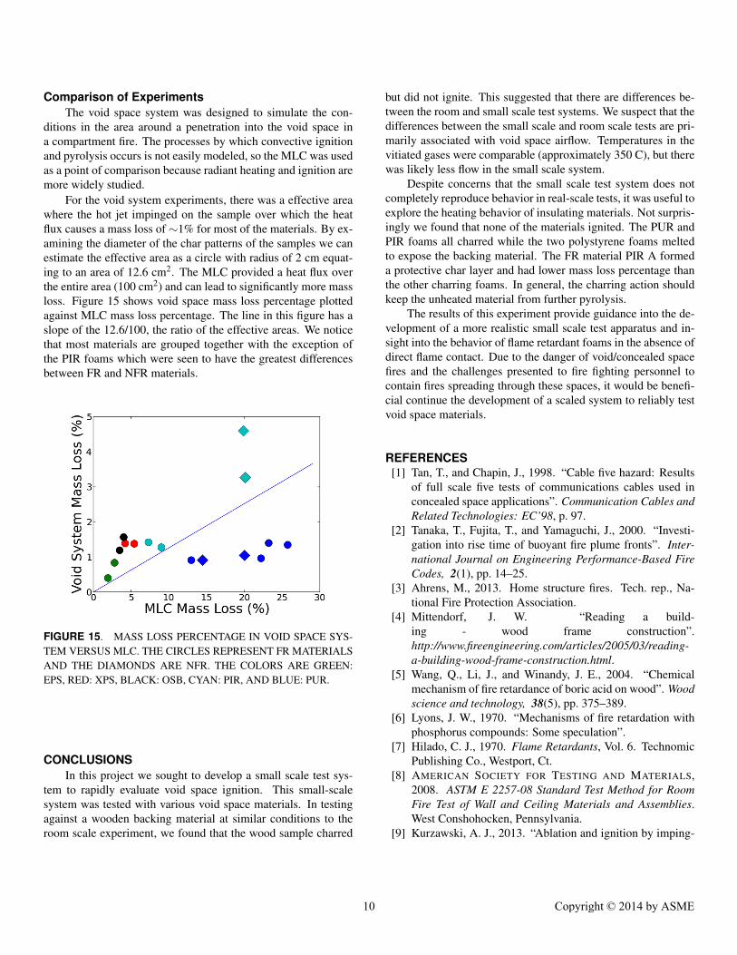
For the void system experiments, there was a effective areawhere the hot jet impinged on the sample over which the heatflux causes a mass loss of ∼1% for most of the materials. By ex-amining the diameter of the char patterns of the samples we canestimate the effective area as a circle with radius of 2 cm equat-ing to an area of 12.6 cm2. The MLC provided a heat flux overthe entire area (100 cm2) and can lead to significantly more massloss. Figure 15 shows void space mass loss percentage plottedagainst MLC mass loss percentage. The line in this figure has aslope of the 12.6/100, the ratio of the effective areas. We noticethat most materials are grouped together with the exception ofthe PIR foams which were seen to have the greatest differencesbetween FR and NFR materials.
FIGURE 15. MASS LOSS PERCENTAGE IN VOID SPACE SYS-TEM VERSUS MLC. THE CIRCLES REPRESENT FR MATERIALSAND THE DIAMONDS ARE NFR. THE COLORS ARE GREEN:EPS, RED: XPS, BLACK: OSB, CYAN: PIR, AND BLUE: PUR.
CONCLUSIONSIn this project we sought to develop a small scale test sys-
tem to rapidly evaluate void space ignition. This small-scalesystem was tested with various void space materials. In testingagainst a wooden backing material at similar conditions to theroom scale experiment, we found that the wood sample charred
but did not ignite. This suggested that there are differences be-tween the room and small scale test systems. We suspect that thedifferences between the small scale and room scale tests are pri-marily associated with void space airflow. Temperatures in thevitiated gases were comparable (approximately 350 C), but therewas likely less flow in the small scale system.
Despite concerns that the small scale test system does notcompletely reproduce behavior in real-scale tests, it was useful toexplore the heating behavior of insulating materials. Not surpris-ingly we found that none of the materials ignited. The PUR andPIR foams all charred while the two polystyrene foams meltedto expose the backing material. The FR material PIR A formeda protective char layer and had lower mass loss percentage thanthe other charring foams. In general, the charring action shouldkeep the unheated material from further pyrolysis.
The results of this experiment provide guidance into the de-velopment of a more realistic small scale test apparatus and in-sight into the behavior of flame retardant foams in the absence ofdirect flame contact. Due to the danger of void/concealed spacefires and the challenges presented to fire fighting personnel tocontain fires spreading through these spaces, it would be benefi-cial continue the development of a scaled system to reliably testvoid space materials.
REFERENCES[1] Tan, T., and Chapin, J., 1998. “Cable five hazard: Results
of full scale five tests of communications cables used inconcealed space applications”. Communication Cables andRelated Technologies: EC’98, p. 97.
[2] Tanaka, T., Fujita, T., and Yamaguchi, J., 2000. “Investi-gation into rise time of buoyant fire plume fronts”. Inter-national Journal on Engineering Performance-Based FireCodes, 2(1), pp. 14–25.
[3] Ahrens, M., 2013. Home structure fires. Tech. rep., Na-tional Fire Protection Association.
[4] Mittendorf, J. W. “Reading a build-ing - wood frame construction”.http://www.fireengineering.com/articles/2005/03/reading-a-building-wood-frame-construction.html.
[5] Wang, Q., Li, J., and Winandy, J. E., 2004. “Chemicalmechanism of fire retardance of boric acid on wood”. Woodscience and technology, 38(5), pp. 375–389.
[6] Lyons, J. W., 1970. “Mechanisms of fire retardation withphosphorus compounds: Some speculation”.
[7] Hilado, C. J., 1970. Flame Retardants, Vol. 6. TechnomicPublishing Co., Westport, Ct.
[8] AMERICAN SOCIETY FOR TESTING AND MATERIALS,2008. ASTM E 2257-08 Standard Test Method for RoomFire Test of Wall and Ceiling Materials and Assemblies.West Conshohocken, Pennsylvania.
[9] Kurzawski, A. J., 2013. “Ablation and ignition by imping-
10 Copyright © 2014 by ASME

ing jet flows”. Master’s thesis, The University of Texas atAustin.
[10] Wen, M., and Jang, K., 2003. “An impingement cooling ona flat surface by using circular jet with longitudinal swirlingstrips”. International Journal of Heat and Mass Transfer,46(24), pp. 4657–4667.
11 Copyright © 2014 by ASME