fnw fig. 40 —installation and maintenance
TRANSCRIPT
A.3. Branch Connection Anchors. Figure 5B is another illustration of the proper anchoring that should be provided in a line with a branch connection. The anchor shown at the tee and elbow connections must be designed to withstand both the thrust and any other forces imposed on the system at these points. Again emphasis is placed on the relative location of the joints, their anchoring points and the pipe guides.
INTRODUCTION: It can be stated generally that the proper location of rubber expansion joints is close to a main anchoring point. Following the joint in the line, a pipe guide or guides should be installed to keep the pipe in line and prevent undue displacement of this line. This is the simplest application of a joint, namely, to absorb the expansion and contraction of a pipeline between fixed anchor points.
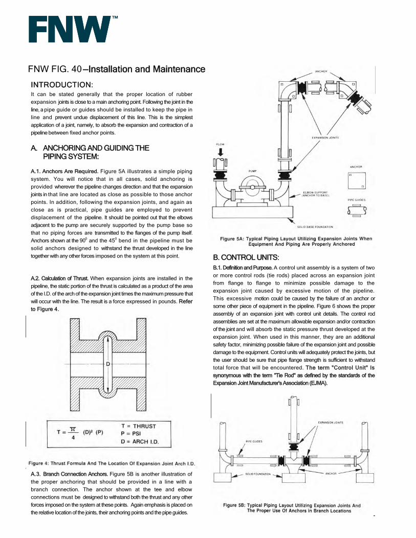
A.1. Anchors Are Required. Figure 5A illustrates a simple piping system. You will notice that in all cases, solid anchoring is provided wherever the pipeline changes direction and that the expansion joints in that line are located as close as possible to those anchor points. In addition, following the expansion joints, and again as close as is practical, pipe guides are employed to prevent displacement of the pipeline. It should be pointed out that the elbows adjacent to the pump are securely supported by the pump base so that no piping forces are transmitted to the flanges of the pump itself. Anchors shown at the 900 and the 450 bend in the pipeline must be solid anchors designed to withstand the thrust developed in the line together with any other forces imposed on the system at this point.
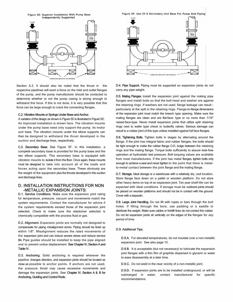
A.2. Calculation of Thrust. When expansion joints are installed in the pipeline, the static portion of the thrust is calculated as a product of the area of the I.D. of the arch of the expansion joint times the maximum pressure that will occur with the line. The result is a force expressed in pounds. Refer to Figure 4.
A. ANCHORING AND GUIDING THE PIPING SYSTEM:
B. CONTROL UNITS: B.1. Definition and Purpose. A control unit assembly is a system of two or more control rods (tie rods) placed across an expansion joint from flange to flange to minimize possible damage to the expansion joint caused by excessive motion of the pipeline. This excessive motion could be caused by the failure of an anchor or some other piece of equipment in the pipeline. Figure 6 shows the proper assembly of an expansion joint with control unit details. The control rod assemblies are set at the maximum allowable expansion and/or contraction of the joint and will absorb the static pressure thrust developed at the expansion joint. When used in this manner, they are an additional safety factor, minimizing possible failure of the expansion joint and possible damage to the equipment. Control units will adequately protect the joints, but the user should be sure that pipe flange strength is sufficient to withstand total force that will be encountered. The term "Control Unit" Is synonymous with the term "Tie Rod" as defined by the standards of the Expansion Joint Manufacturer's Association (EJMA).
FNW FIG. 40 —Installation and Maintenance

C. OTHER INSTALLATIONS: C.1. Vibration Mounts Under Foundation. Figure 5D shows a very
common pump installation. Instead of being mounted on a solid
foundation, the pump is supported off the floor on vibration mounts.
There is nothing wrong with this type of installation. The supplier of the
vibration mounts should be made aware of the fact that these mounts
must be designed, not only to support the weight of the pump, its motor
and base, but must also absorb the vertical thrust that will occur in both
the suction and discharge lines. To calculate thrust see Chapter IV,
B.2.A. Extension. Control units must be used when it is not feasible
in a given structure to provide adequate anchors in the proper
location. In such cases, the static pressure thrust of the system will
cause the expansion joint to extend to the limit set by the control
rods which will then preclude the possibility of further motion that
would over-elongate the joint. Despite the limiting action that
control rods have on the joint, they must be used when proper
anchoring cannot be provided. It cannot be emphasized too
strongly that rubber expansion joints, by virtue of their function, are
not designed to take end thrusts and, in all cases where such are
likely to occur, proper anchoring is essential. If this fact is ignored,
premature failure of the expansion joint is a foregone conclusion.
B.2.B. Compression. Pipe sleeves or inside nuts can be installed
on the control rods. The purpose of the sleeve is to prevent
excessive compression in the expansion joint. The length of this
pipe sleeve should be such that the expansion joint cannot be
compressed beyond the maximum allowable compression figure
stated by the manufacturer. See Table V and Figure 6.
B.3. Specifications. For control unit dimensional specifications see
Appendix C. These specifications are recommended for standard
construction type expansion joints. The exact number of control rods
should be selected on the basis of the actual design/test pressure of
the system. Always specify the mating flange thickness when ordering
control unit assemblies. See Appendix D.
B.4. Illustration of the Use of Control Rods. Figure 5C demonstrates the type of piping connections that must be used in the event it is impossible to employ anchoring. The anchor point at the upper 90° elbow in the discharge line has been eliminated. (It is shown in Figure 5A.) In this situation, it is necessary to employ properly designed control units with the joints located in this non-anchored line. Without the use of these control units, the pipeline between the pump and the anchor, at the 45° bend, would be severely displaced due to elongation in the flexible rubber expansion joint. This elongation would proceed until the joints rupture. The use of control units in this case permits expansion of the pipeline in both the vertical and horizontal direction between the pump and the anchor, at the 45° bend. However, it does preclude the possibility of contraction in these respective lines as the further extension of the expansion joint is impossible because of the control units.
For significant lateral movement spherical washers are recommended.
B.2. Use in Restraining the Piping System. Control units may be
required to limit both extension and compression movements.
Figure 5D: Typical Pump Installation With Expansion Joints Utilizing
Spherical washer equal axial and lateral load distribution
C.2. Vibration Mounts or Springs Under Base and Anchor.
A variation of the design as shown in Figure 5D is illustrated in Figure 5E.
An improved installation is shown here. The vibration mounts
under the pump base need only support the pump, its motor
and base. The vibration mounts under the elbow supports can
then be designed to withstand the thrust developed in the
suction and discharge lines, respectively.
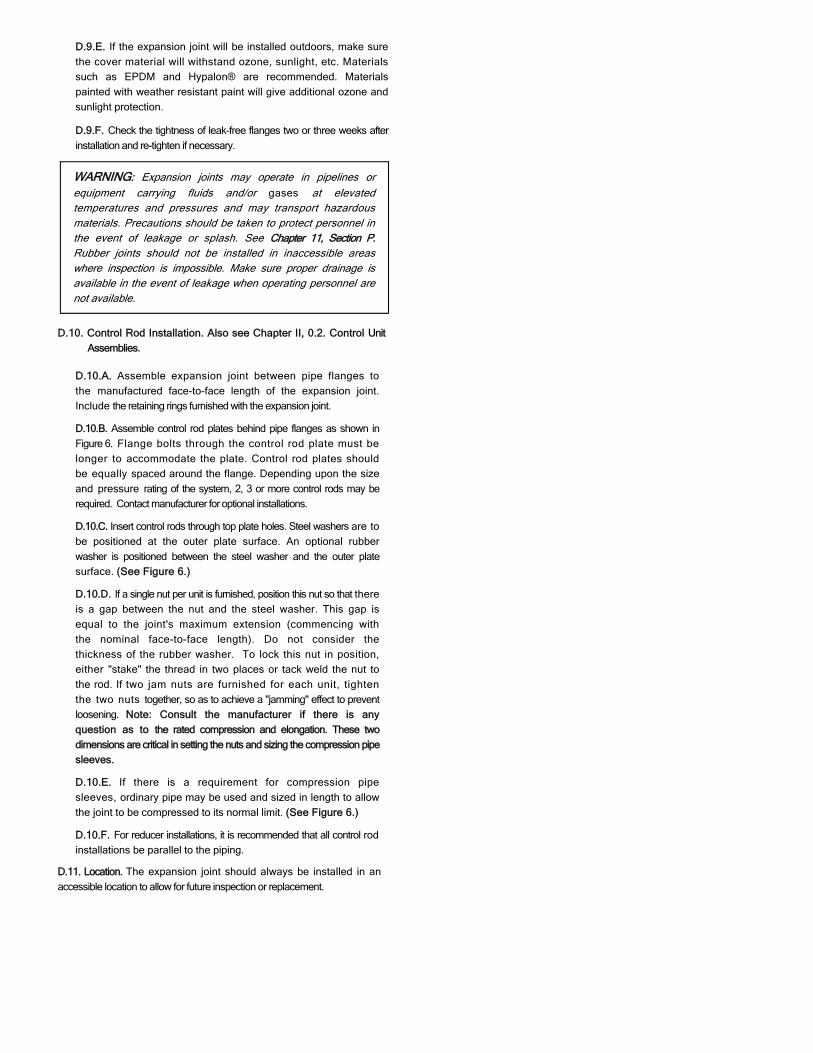
C.3. Secondary Base. See Figure 5F. In this installation, a
complete secondary base is provided for the pump base and the
two elbow supports. This secondary base is equipped with
vibration mounts to isolate it from the floor. Once again, these mounts
must be designed to take into account all of the loads and
forces acting upon the secondary base. These obviously are
the weight of the equipment plus the thrusts developed in the suction
and discharge lines.
D. INSTALLATION INSTRUCTIONS FOR NON-METALLIC EXPANSION JOINTS:
D.1. Service Conditions. Make sure the expansion joint rating
for temperature, pressure, vacuum and movements match the
system requirements. Contact the manufacturer for advice if
the system requirements exceed those of the expansion joint
selected. Check to make sure the elastomer selected is
chemically compatible with the process fluid or gas.
D.2. Alignment. Expansion joints are normally not designed to
compensate for piping misalignment errors. Piping should be lined up
within 1/8". Misalignment reduces the rated movements of
the expansion joint and can induce severe stress and reduce service
life. Pipe guides should be installed to keep the pipe aligned
and to prevent undue displacement. See Chapter IV, Section A and
Table IV.
D.3. Anchoring. Solid anchoring is required wherever the
pipeline changes direction, and expansion joints should be located as
close as possible to anchor points. If anchors are not used,
the pressure thrust may cause excessive movements and
damage the expansion joints. See Chapter IV, Section A & B for
Anchoring, Guiding and Control Rods.
D.4. Pipe Support. Piping must be supported so expansion joints do not
carry any pipe weight.
D.5. Mating Flanges. Install the expansion joint against the mating pipe
flanges and install bolts so that the bolt head and washer are against
the retaining rings. If washers are not used, flange leakage can result -
particularly at the split in the retaining rings. Flange-to-flange dimensions
of the expansion joint must match the breech type opening. Make sure the
mating flanges are clean and are flat-face- type or no more than 1/16"
raised-face-type. Never install expansion joints that utilize split retaining
rings next to wafer type check or butterfly valves. Serious damage can
result to a rubber joint of this type unless installed against full face flanges.
D.6. Tightening Bolts. Tighten bolts in stages by alternating around the
flange. If the joint has integral fabric and rubber flanges, the bolts should
be tight enough to make the rubber flange O.D. bulge between the retaining
rings and the mating flange. Torque bolts sufficiently to assure leak-free
operation at hydrostatic test pressure. Bolt torquing values are available
from most manufacturers. If the joint has metal flanges, tighten bolts only
enough to achieve a seal and never tighten to the point that there is metal-
to-metal contact between the joint flange and the mating flange.
D.7. Storage. Ideal storage is a warehouse with a relatively dry, cool location.
Store flange face down on a pallet or wooden platform. Do not store
other heavy items on top of an expansion joint. Ten year shelf-life can be
expected with ideal conditions. If storage must be outdoors joints should
be placed on wooden platforms and should not be in contact with the ground.
Cover with a tarpaulin.
D.8. Large Joint Handling. Do not lift with ropes or bars through the bolt
holes. If lifting through the bore, use padding or a saddle to
distribute the weight. Make sure cables or forklift tines do not contact the rubber.
Do not let expansion joints sit vertically on the edges of the flanges for any
period of time.
D.9. Additional Tips.
D.9.A. For elevated temperatures, do not insulate over a non-metallic
expansion joint. See also page 10.
D.9.B. It is acceptable (but not necessary) to lubricate the expansion
joint flanges with a thin film of graphite dispersed in glycerin or water
to ease disassembly at a later time.
D.9.C. Do not weld in the near vicinity of a non-metallic joint.
D.9.D. If expansion joints are to be installed underground, or will be
submerged in water, contact manufacturer for specific
recommendations.
Section A.2. It should also be noted that the thrust in the
respective pipelines will exert a force on the inlet and outlet flanges
of the pump, and the pump manufacturer should be contacted to
determine whether or not the pump casing is strong enough to
withstand this force. If this is not done, it is very possible that this
force can be large enough to crack the connecting flanges.
D.9.E. If the expansion joint will be installed outdoors, make sure
the cover material will withstand ozone, sunlight, etc. Materials
such as EPDM and Hypalon® are recommended. Materials
painted with weather resistant paint will give additional ozone and
sunlight protection.
D.9.F. Check the tightness of leak-free flanges two or three weeks after
installation and re-tighten if necessary.
WARNING: Expansion joints may operate in pipelines or equipment carrying fluids and/or gases at elevated temperatures and pressures and may transport hazardous materials. Precautions should be taken to protect personnel in the event of leakage or splash. See Chapter 11, Section P. Rubber joints should not be installed in inaccessible areas where inspection is impossible. Make sure proper drainage is available in the event of leakage when operating personnel are not available.
D.11. Location. The expansion joint should always be installed in an
accessible location to allow for future inspection or replacement.
D.10. Control Rod Installation. Also see Chapter II, 0.2. Control Unit
Assemblies.
D.10.A. Assemble expansion joint between pipe flanges to
the manufactured face-to-face length of the expansion joint.
Include the retaining rings furnished with the expansion joint.
D.10.B. Assemble control rod plates behind pipe flanges as shown in
Figure 6. Flange bolts through the control rod plate must be
longer to accommodate the plate. Control rod plates should
be equally spaced around the flange. Depending upon the size
and pressure rating of the system, 2, 3 or more control rods may be
required. Contact manufacturer for optional installations.
D.10.C. Insert control rods through top plate holes. Steel washers are to
be positioned at the outer plate surface. An optional rubber
washer is positioned between the steel washer and the outer plate
surface. (See Figure 6.)
D.10.D. If a single nut per unit is furnished, position this nut so that there
is a gap between the nut and the steel washer. This gap is
equal to the joint's maximum extension (commencing with
the nominal face-to-face length). Do not consider the
thickness of the rubber washer. To lock this nut in position,
either "stake" the thread in two places or tack weld the nut to
the rod. If two jam nuts are furnished for each unit, tighten
the two nuts together, so as to achieve a "jamming" effect to prevent
loosening. Note: Consult the manufacturer if there is any
question as to the rated compression and elongation. These two
dimensions are critical in setting the nuts and sizing the compression pipe
sleeves.
D.10.E. If there is a requirement for compression pipe
sleeves, ordinary pipe may be used and sized in length to allow
the joint to be compressed to its normal limit. (See Figure 6.)
D.10.F. For reducer installations, it is recommended that all control rod
installations be parallel to the piping.