fm 23-9 - bits68).pdffm 23-9 c l change headquarters department of the army no. 1 washington, d.c.,...
TRANSCRIPT

FM 23-9DEPARTMENT OF THE ARMY FIELD MANUAL
RIFLE,5.56-MM,XM16E1
HEADQUARTERS, DEPARTMENT OF THE ARMYJULY 1966

FM 23-9C l
CHANGE HEADQUARTERSDEPARTMENT OF THE ARMY
No. 1 WASHINGTON, D.C., 2 February 1968
RIFLE, 5.56-MM, M16A1FM 23-9, 12 July 1966, is changed as follows: cartridge to press the takedown pin (fig. 7) until
The title is changed to read as shown above. the upper receiver swings free of the lower re-In paragraphs 1, 3, 5, 6, 10, 15, 16, 20, 22, ceiver (fig. 8).
23, 25, 31, 32, and 35, wherever the term "XM Caution: The takedown pin does not come out16E1" appears, it is changed to read "M16A1." of the receiver.
In figures 1 and 19, the term "XM16E1" is d. Again using the nose of a cartridge, presschanged to read "M16A1." the receiver pivot pin (fig. 9). Separate the upper
Page 3, paragraph 3b. In line 3 "or" is changed and lower receiver groups (fig. 10) and place theto read "of." lower receiver group on the table.
Page 3. Paragraph 4a is superseded as follows: Caution: The receiver pivot pin does not comeout of the receiver.a. Weights.
e. Pick up the upper receiver group; keep thePounds
Rifle without magazine and sling_ _______________ 6.5 muzzle to the left. Grasp the charging handle,Empty magazine (aluminum, 20 rounds)___________ . 2 pressing in on the latch, and pull to the rear (fig. 5)Full magazine (20 rounds) -______---- ___-------- .7 to withdraw the bolt carrier from the receiver.*Sling, Ml______________________________________ -4 Grasp the bolt carrier and pull it from the receiverFiring weight (fully loaded with sling)____________- 7. 6 (fig. 11). When the bolt carrier is removed, theBipod, M3-_____________________________________ .6Bipod case -___________________________________-- .2 charging handle will fall free of its groove in theBayonet-knife, M7 ________________-______--_____ . 6 receiver when pulled to the rear (fig. 12). Place theScabbard, M8A1 _________________________________ .3 receiver on the table.
*Sling, small arms, FSN 105-714-9749, is an authorized sub- f. To disassemble the bolt carrier group, pressstitute for sling MI. This sling is extra long and will allow a out the firing pin retaining pin by using the nose offirer to carry the weapon slung across the front of his body Ina position which allows him to take both hands from the weapon, a cartridge (fig. 13). Elevate the front of the boltbut keep it available for use. It would be especially useful for carrier and allow the firing pin to drop from itspersonnel designated as automatic riflemen or for people who mustcarry such equipment as radios and binoculars. well in the bolt (fig. 14). Rotate the bolt until the
Page 5, paragraph 4e. In line 1, "3,150 feet per cam pin is clear of the bolt carrier key and removesecond (approx.)" is changed to read "3,250 feet the cam pin by rotating it 900 (l/4-turn) and liftingper second (approx.)." it out of the well in the bolt and bolt carrier (fig.
Page 6. Paragraph 7 is superseded as follows: 15). After the cam pin is removed, the bolt can beremoved easily from its recess in the bolt carrier
7. Field Stripping (fig. 16). Remove the extractor by first pushing thea. Remove the sling. extractor pin out with the firing pin, then, whileb. Remove the handguards by placing the butt maintaining pressure on the extractor with the in-
of the rifle on a flat surface with the muzzle up. dex finger, withdraw the firing pin from the ex-Pull down on the slipring until the lower lip of tractor pinhole. Release the pressure from thethe handguard is clear; pull out and down on the extractor and remove. The extractor should be dis-handguard until the upper lip is free of the hand- assembled only when necessary for cleaning, andguard cap (fig 18). Repeat the same operation to disassembly should be supervised. Since the ex-remove the second handguard. Considerable pres- tractor pin is quite small: it should be handled withsure must be used to force the slipring down. care to prevent loss or damage.
Note: Handguards should not be removed when the Note. The extractor spring should not be removed fromupper and lower receiver groups are separated because of the extractor. If the spring falls out of its recess it shouldpotential damage to the forward assist assembly. be replaced by the unit armorer.
c. Place the weapon on a flat surface on its right j. Using the index finger of the right hand, pushside with the muzzle to the left. Use the nose of the in on the buffer assembly. With the nose of a car-
TAGO 767A-Jan. 300471'-68 1

tridge, or the tip of the firing pin, push down on c. Grasp the upper receiver with the carryingthe buffer retainer. Depress the hammer to the rear handle up. Place the charging handle into the(downward) sufficiently to allow the buffer as- groove in the top of the upper receiver. The lugssembly to clear the hammer. Remove the buffer on the charging handle must be seated in theirassembly and the spring (fig. 17). grooves in the receiver. Place the bolt carrier
Note. The action spring is under pressure and care group into the open end of the receiver, insuringmust be taken in removing it. that the bolt carrier key is in the slot on the under-
h. This completes field stripping (fig. 19). side of the charging handle and the bolt is for-ward in the unlock position. Push forward on the
Note. Detailed disassembly consists of removing the re- bolt carrier group and charging handle until fullymaining operating parts from the lower receiver (fig. 20)and is not authorized at user and/or organizational level. seated.The individual soldier has no need to disassemble the d. Place the upper receiver group and lowerweapon beyond field stripping. Only qualified maintenance receiver group together and reseat the receiverpersonnel are authorized to remove any other parts from pivot pin.the weapon.
e. With the hammer cocked and selector leverCaution: Steps b and g above should be per- in the safe position, close the weapon and seat the
formed only when absolutely necessary for takedown pin.care and cleaning. f. Replace the handguards and be sure that the
Page 13. Paragraph 8 is superseded as follows: slipring is fully seated on the lower lip of bothsections of the handguards. Care must be takento prevent damage to the upper and lower lips
To assemble the rifle, reverse the procedures of and to insure proper seating.disassembly. g. A complete function check of the rifle con-
a. To assemble the buffer assembly, insert the sists of checking the operation of the weapon whileassembly, spring end first, into the lower receiver the selector is in the SAFE, SEMI, and AUTOextension, depress the cocked hammer to allow pas- positions. The following sequence is used for asage of the buffer assembly, depress the buffer re- rapid, complete check. Any portion of the checktainer with the nose of a cartridge, or tip of the may be used alone to determine the operationalfiring pin, seat the buffer assembly and release the condition of any specific fire selection.buffer retainer.
b. To assemble the bolt carrier group, grasp the Note. Disengage the takedown pin and open receivers.bolt and the extractor with spring. Seat the ex- Hammer shall be in the cocked position.tractor in the extractor recess, apply pressure on (1) SAFE position. Pull trigger, hammerthe extractor to aline the pinhole and insert the should not fall.extractor pin. Pick up the bolt carrier, key up and (2) SEMI position. Pull trigger, hammerto the front, insert the bolt into the front of the should fall. Hold trigger to rear, recockbolt carrier, insuring that the ejector is down and hammer and release trigger. Hammerto the left. Replace the cam pin into its well and should transfer from hammer hooks androtate the cam pin 90 ° (1/4-turn) to aline the holes disconnect to the hammer and sear en-for the firing pin in the bolt and cam pin. Grasp the gagement.lugged rim of the bolt and turn until the cam pin is (3) A UTO position. Pull trigger, hammerdirectly under the bolt carrier key. Insert the firing should fall. Hold trigger to the rear andpin through the open end of the bolt carrier and recock hammer. Hammer is now underseat fully. Insert the firing nin retaining nin (if Isear. Sill olig triggerresistance is encountered, rotate pin while to the rear, push forward on automaticinserting), sear. The hammer should fall. Still hold-
Caution: Do not attempt to spread the slotted ing trigger to the rear, recock hammer,end of the firing pin retaining pin. release trigger and push forward on auto-
matic sear. Hammer should transfer toNote. Check for proper assembly by elevating the frontof the bolt. If the firing pin drops out, the firing pin re- the sear engagement. Move selector levertaining pin is not between the front and rear spool and to SAFE or SEMI position. Close re-the bolt carrier group is improperly assembled. ceivers and engage takedown pin.
2TAGO 767A
Caution: Failure to move selector c. Disassembly and Assembly of the Magazine.lever to SAFE or SEMI position, be- (1) To properly perform maintenance on thefore closing receivers, will damage magazine, it must be disassembled.automatic sear. (2) The magazine is disassembled in the fol-
(4) SEMIF position. Pull charging handle to lowing manner:(a) Hold the magazine in the left hand,the rear. Make certain chamber is clear, (a) Hold the magazine in the left
open end to the left, short edge nearthen release charging handle. Pull thebody.trigger. Hammer should fall.
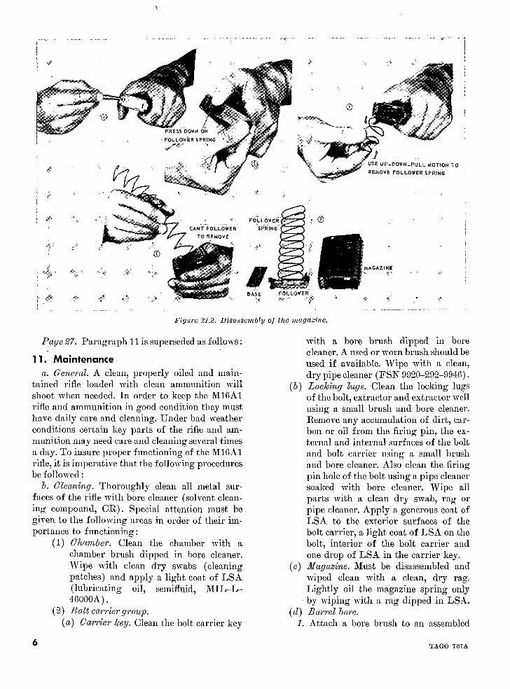
(b) Insert the nose of a cartridge into thePage 14, figure 17. In the caption, "action hole in the base of the magazine, de-
spring guide assembly" is changed to read "buffer pressing the spring steel lock band andassembly." at the same time exerting a slight pres-
Page 17. Paragraph 9 is superseded as follows: sure on the base pushing it away fromthe body or toward the long edge of the
9. Operation magazine (1, fig. 21.2).
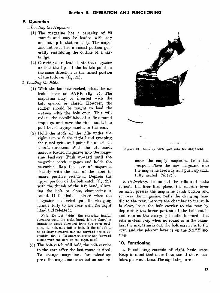
a. Loading the Magazine. (c) Slide the base forward until it is free(1) The magazine has a capacity of 20 of the tabs (2, fig. 21.2).
rounds and may be loaded with any Note. Keep the left thumb over the follower
amount up to that capacity. The maga- spring to prevent it from jumping out of thezine follower has a raised portion gen- magazine.erally resembling the outline of a car- (d) To remove the follower spring, dis-tridge. engage it from the tabs on the maga-
(2) Cartridges are loaded into the magazine zine first from one side and then theso that the tips of the bullets point in the other until it is free of the magazinesame direction as the raised portion of the (3, fig. 21.2).follower (fig. 21). (e) The follower, attached to the end of the
magazine must be "canted" in order toNote. Rounds in the magazine should be re- magazine must be "canted" in order tomoved and checked daily for corrosion and dents clear the tabs (4, fig. 21.2).and wiped off with a dry cloth. (f) Clean the exterior and interior of the
Caution: Do not load or attempt to magazine with a dry patch. The mar'load more than 20 rounds in the maga- zine is kept dry. The magaK ' .zine. Overloading will deform the lips is lightly oiledof the magazine and cause malfunc- (3) To assemble the magazine, the parts aretions. replaced in the reverse order of removal.
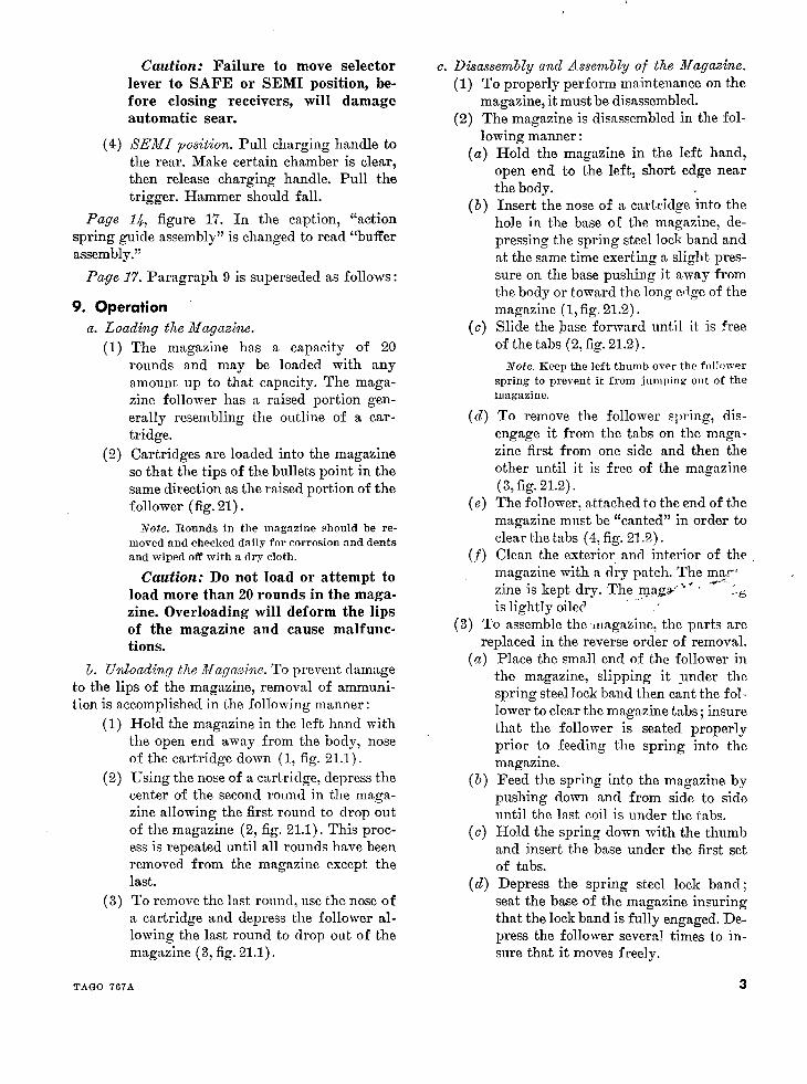
(a) Place the small end of the follower inb. Unloading the Magazine. To prevent damage the magazine, slipping it under the
to the lips of the magazine, removal of ammuni- spring steel lock band then cant the foltion is accomplished in the following manner: lower to clear the magazine tabs; insure
(1) Hold the magazine in the left hand with that the follower is seated properlythe open end away from the body, nose prior to feeding the spring into theof the cartridge down (1, fig. 21.1). magazine.
(2) Using the nose of a cartridge, depress the (b) Feed the spring into the magazine bycenter of the second round in the maga- pushing down and from side to sidezine allowing the first round to drop out until the last coil is under the tabs.of the magazine (2, fig. 21.1). This proc- (c) Hold the spring down with the thumbess is repeated until all rounds have been and insert the base under the first setremoved from the magazine except the of tabs.last. (d) Depress the spring steel lock band;
(3) To remove the last round, use the nose of seat the base of the magazine insuringa cartridge and depress the follower al- that the lock band is fully engaged. De-lowing the last round to drop out of the press the follower several times to in-magazine (3, fig. 21.1). sure that it moves freely.
TAGO 767A 3
d. Loading the Rifle. their hands, using the left index finger to depressthe upper portion of the bolt catch.
(1) With the hammer cocked, place the selec- Note. Do not "ride" the charging handle for-
tor lever on SAFE (fig. 3). The maga- ward with the right hand. If the charging handle
zine may be inserted with the bolt opened is eased forward from the open position, the boltor closed. However, the soldier should be may fail to lock. If the bolt fails to go fully for-
ward, use the forward assist assembly (fig. 1).taught to load the weapon with the bolt To operate, strike the forward assist with the
open. This will reduce the possibilities of heel of the right hand.
a first round stoppage and save the time (3) The bolt catch will hold the bolt carrierneeded to pull the charging handle to the to the rear after the last round is fired. Torear. change magazines for reloading, press the
(2) Hold the stock of the rifle under the right magazine catch button and remove thearm with the right hand grasping the pis- empty magazine from the weapon. Placetol grip, and point the muzzle in a safe the new magazine into the magazine hous-direction. With the left hand, insert a ing and push up until fully seated (b(2)loaded magazine into the magazine hous- above).
e. Unloading. To unload the rifle and make iting. Push upward until the magazinecatch engages and holds the magazine safe, the firer first places the selector lever on safe,catch engages and holds the magazine.
Depress the upper portion of the bolt presses the magazine catch button and removesthe magazine, pulls the charging handle to the
catch (fig. 22) with the tlhumb of the left rear, inspects the chamber to insure it is clear,hand, allowing the bolt to close, chamber- locks the bolt carrier to the rear by depressing theing a round. If the bolt is closed when the lower portion of the bolt catch, and returns themagazine is inserted, pull the charging charging handle forward. The rifle is clear onlyhandle fully to the rear with the right when no round is in the chamber, the magazine ishand and release. it. out, the bolt carrier is to the rear, and the selector
Note: Left-handed personnel should follow lever is on the SAFE setting.the procedure above by reversing the position of Figures 21.1 and 21.2 are added as follows:
TAGO 767A

1 ! ['IPRESS DOWN ON LLOARTRI
TAGO 767ATAGO 76TA
PRESS DOWN ON
,FOLLOWER SPRING. ta ,
USE UP-DOWN-PULL MOTION TO
REMOVE FOLLOWER SPRING
CANT FOLL OWER SSRI NG
_;; 77" O TO REMOVE I
i X~lk ;P- ........:....... ...
*g r en w MA GAZINN
Figure 21.2. Disassembly of the rIagaziile.
Page 27. Paragraph 11 is superseded as follows: with a bore brush dipped in borecleaner. A used or worn brush should be
11. Maintenance used if available. Wipe with a clean,a. General. A clean, properly oiled and main- dry pipe cleaner (FSN 9920-292-9946).
tained rifle loaded with clean ammunition will (b) Locking lugs. Clean the locking lugsshoot when needed. In order to keep the M16A1 of the bolt, extractor and extractor wellrifle and ammunition in good condition they must using a small brush and bore cleaner.have daily care and cleaning. Under bad weather Remove any accumulation of dirt, car-conditions certain key parts of the rifle and am- bon or oil from the firing pin, the ex-munition may need care and cleaning several times ternal and internal surfaces of the bolta day. To insure proper functioning of the M16A1 and bolt carrier using a small brushrifle, it is imperative that the following procedures and bore cleaner. Also clean the firingbe followed: pin hole of the bolt using a pipe cleaner
b. Cleaning. Thoroughly clean all metal sur- soaked with bore cleaner. Wipe allfaces of the rifle with bore cleaner (solvent clean- parts with a clean dry swab, rag oring compoumd, CR.). Special attention must be pipe cleaner. Apply a generous coat ofgiven to the following areas in order of their im- LSA to the exterior surfaces of theportance to functioning: bolt carrier, a light coat of LSA on the
(1) Chacber. Clean the chamber with a bolt, interior of the bolt carrier andchamber brush dipped in bore cleaner. one drop of LSA in the carrier key.Wipe with clean dry swabs (cleaning (c) Magazine. Must be disassembled andpatches) and apply a light coat of LSA wiped clean with a clean, dry rag.(lubricating oil, semifluid, MIL-L- Lightly oil the magazine spring only46000A). - by wiping with a rag dipped in LSA.
(2) Bolt carrier group. (d) Barrel bore.(a) Carrier key. Clean the bolt carrier key 1. Attach a bore brush to an assembled
6 TAGO 767A
cleaning rod, dip in bore cleaner, and attached to a section of cleaning rod.brush the bore thoroughly. Brush the The top of the gas tube can bebore from chamber to muzzle using cleaned by inserting the rod andstraight through strokes. brush in the back of the receiver. The
sides and bottom of the gas tube canNote. Do not reverse direction of brushwhile in the bore. Push the brush through be cleaned from the bottom of thethe bore until it extends beyond the muzzle. receiver.Continue until the bore is well covered 3. Wipe all parts dry.with bore cleaner. Remove the brush from 4. Apply a generous coat of LSA tothe cleaning rod, attach the slotted tip, and the interior surfaces of the upperdry the bore by pushing through clean dryswabs. Continue until swabs come out clean receiver.and dry. Care should be used to support (f) Lower receiver.the cleaning rod while inserting to prevent i. Cleaning will not require detailed dis-flexing or breakage. assembly of the lower receiver group.
2. After cleaning, lubricate the bore with Using a swab or bristle brush witha lightly oiled swab to prevent rust bore cleaner, remove carbon, dirt andand pitting. Lightly oil the lugs in sand from the lower receiver. Drythe barrel extension. and generously lubricate with LSA.
(e) Upper receiver. 2. After extensive use, acids caused by1. Use a swab or brush to clean the upper perspiration should be removed from
receiver of powder fouling with bore exterior surfaces using a rag or swabcleaner. with bore cleaner, then wipe dry and
2. Clean the protruding gas tube in the apply a light coat of LSA.receiver with a worn bore brush Page B8. Figure 33 is superseded as follows:
TAGo 767A 7

1 Bore brush 3 Chamber and receiver brush2 Lubricant Case 4 Cleaning rod
a. Greaseb. Oil
Figbre 33. leaOinig eqlipment.
TAG(O 767A

Page 29. Figure 35 is superseded as follows:
Interval and sequence No. Operator's daily schedule
Before During After Item to be inspected Procedures Paragraphfiring firing firing reference
1_ ..__ Rifle_ ----------__ Wipe oil from bore and chamber ---- _--.........__ 11b.2_ . .._ Ammunition ------ Wipe oil, grease, sand, and other foreign matter from the 9a.
ammunition with a dry swab.3 ----- Rifle_ ----------- _ Retract bolt to assure free movement between bolt carrier 11b.
and gas tube.4_ ---- Rifle -_-- ___ --- _ Function check to assure proper operation --- _-_--- __--- 8g.5 ----- Rifle ------------ Check magazine for positive retention and functioning 10c(2).
of bolt catch.6 Rifle ------------- Clean and lubricate. Pay particular attention to cleaning l1b.
the bolt carrier key and chamber.
Figure 35. Preventive maintenance checks and services.
Page 30. Paragraph 12c is added after para- and depress the detent several times. Wipe excessgraph 12b. oil off with a dry swab.
c. To clean the detent and detent spring on the Page 30. Section IV is superseded as follows:front and rear sights, apply several drops of LSA
Section IV. STOPPAGES, IMMEDIATE AND REMEDIAL ACTION
14. Stoppages assist assembly to assure bolt closure. Attempt toA stoppage is any unintentional interruption fire the weapon. If the weapon fails to fire, it must
be inspected to determine the cause of malfunctionin the cycle of functioning. Immediate or reme- and appropriate action taken.dial action must be taken to clear the stoppage.
dial action must be taken to clear the stoppage. c. If a cartridge or cartridge case is not ejected,15. Immediate Action check for a round in the chamber. If the chamber
is clear, release the charging handle to feed aImmediate action is the unhesitating applica- round, strike the forward assist assembly, and at-
tion of a probable remedy to reduce a stoppage tempt to fire. If the weapon still fails to fire, itwithout investigating the cause. Immediate action must be inspected to determine the cause of mal-to clear a stoppage with the M16A1 rifle is as function and appropriate action taken. -follows: d. If a cartridge or case is noted in the chamber,
a. Strike the forward assist assembly to insure it must be removed before attempting to reloadthat the extractor has engaged the round. Tap up- and recycle the weapon.ward on the bottom of the magazine to insure itis fully seated. Pull the charging handle fully to 15.1. Remedial Actionthe rear. Observe for ejection of a complete car- When the application of immediate action failstridge or cartridge case. to reduce the stoppage the cause of the stoppage
b. If a cartridge or case is ejected, release the will require investigation by remedial action. Acharging handle to feed a new round (do not ride suggested troubleshooting guide is shown in thethe charging handle forward). Strike the forward chart below.
TAGO 767A 9
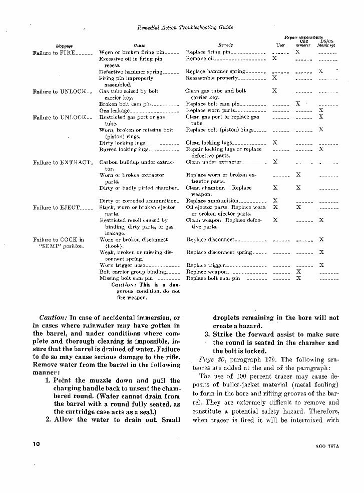
Remedial Action Troubleshooting Guide
Repair responsibilityUnit DS/GS
Stoppage Cause Remedy User armorer Maint spt
Failure to FIRE -_--- Worn or broken firing pin ---- Replace firing pin ----------_ ------ XExcessive oil in firing pin Remove oil -------- _ _------- X
recess.Defective hammer spring ----- Replace hammer spring _--- -_ -__-__ _---- XFiring pin improperly Reassemble properly --- _-- X _
assembled.Failure to UNLOCK__ Gas tube seized by bolt Clean gas tube and bolt X
carrier key. carrier key.Broken bolt cam pin --------- Replace bolt cam pin ------- _ _----- XGas leakage ---------------- Replace worn parts - _----- -- _ ___--_ _---- X
Failure to UNLOCK__ Restricted gas port or gas Clean gas port or replace gas _----- -_-_- Xtube. tube.
Worn, broken or missing bolt Replace bolt (piston) rings --- _ _--- -- _---- X(piston) rings.
Dirty locking lugs ----------- Clean locking lugs_ ----- _---- XBurred locking lugs ---------- Repair locking lugs or replace -----_ _---- X
defective parts.Failure to EXTRACT_ Carbon buildup under extrac- Clean under extractor ---- X
tor.Worn or broken extractor Replace worn or broken ex- _----- X
parts. tractor parts.Dirty or badly pitted chamber_ Clean chamber. Replace X X
weapon.Dirty or corroded ammunition_ Replace ammunition --------- X
Failure to EJECT ---- Stuck, worn or broken ejector Oil ejector parts. Replace worn X Xparts. or broken ejector parts.
Restricted recoil caused by Clean weapon. Replace defec- X _----- Xbinding, dirty parts, or gas tive parts.leakage.
Failure to COCK in Worn or broken disconnect Replace disconnect ---------- _------..... X"SEMI" position. (hook).
Weak, broken or missing dis- Replace disconnect spring-- -_------.... Xconnect spring.
Worn trigger nose ----------_ Replace trigger -------------- - _--- ------ XBolt carrier group binding ---- Replace weapon _ - .....--- _ ______ XMissing bolt cam pin -------- Replace bolt cam pin -_-- --- ___-_ X
Caution: This is a dan-gerous condition, do notfire weapon.
Caution: In case of accidental immersion, or droplets remaining in the bore will notin cases where rainwater may have gotten in create a hazard.the barrel, and under conditions where corn- 3. Strike the forward assist to make sureplete and thorough cleaning is impossible, in- the round is seated in the chamber andsure that the barrel is drained of water. Failure the bolt is locked.to do so may cause serious damage to the rifle. Page 30, paragraph 176. The following sen-Remove water from the barrel in the following te___e a_ e added at the end of th_ paragraph.manner: LU11CU,3The use of 100 percent tracer may cause de-
1. Point the muzzle down and pull the percent tracer may causecharging handle back to unseat the chai- posits of bullet-jacket material (metal fouling)bered round. (Water cannot drain from to form in the bore and rifling grooves of the bar-the barrel with a round fully seated, as rel. They are extremely difficult to remove andthe cartridge case acts as a seal.) constitute a potential safety hazard. Therefore,
2. Allow the water to drain out. Small when tracer is fired it will be intermixed with
10 AGO 767A

ball ammunition in a ratio no greater than 1: 1 manipulation should be employed to de-with a preferred ratio of 4: 1. liver a heavy volume of fire to engage a
Page 31. Paragraph 19g is added after para- small group of the enemy. When engaginggraph 19/. a formation a specific individual in the
g. Badly dented cartridges, cartridges with group should be selected and engaged forloose bullets, or otherwise defective rounds should maximum effectiveness rather than firingnot be fired. This ammunition must be reported at the group in general.promptly to the technical service representative Page 55. Paragraph 26a(2) (a) is supersededunder whose supervision the ammunition for the as follows:unit involved is maintained and issued. (a) When engaging enemy mass for-
Page 43, paragraph 25b (1). In line 3, "magazine mations at ranges out to 460 meters.feedway" is changed to read "magazine housing." Page 58, paragraph 28b. In line 10, "magazine
Page 45, paragraph 25c(1). In line 10, "maga- feedway" is changed to read "magazine housing."zine feedway" is changed to read "magazine Page 59. After paragraph 29d the following notehousing." is added:
Page 55. Paragraph 26a(1) is superseded asfollows: Note. Adjusting the magazine catch: the magazine
fl(1os S:atorti f Semiautomatic fire is catch should hold the magazines firmly but not interfere(1) Semrniautomaticu a re. Semiautomaticfireis with the magazine removal when the catch button is
employed in any situation where a high pressed. To adjust, press in on the catch button with thedegree of accuracy is required to hit a nose of a cartridge or the end of the cleaning rod, pushingsmall point target; e.g., bunker apertures, the catch out far enough (on left side of weapon) to clearwindows, and scattered formations or the catch housing. To tighten turn the magazine catchsingle enemy personnel or, where the clockwise, to loosen turn counterclockwise.
range to the target is in excess of 460 Page 64, paragraph 31a. In lines 2 and 7 "springmeters. This method of employment con- loaded stud" is changed to read "detent." In sub-sumes the least amount of ammunition paragraph b, lines 2 and 5, "spring loaded stud"and is the most effective. Rapid trigger is changed to read "detent."
By Order of the Secretary of the Army:
HAROLD K. JOHNSON,General, United States Army,
Official: Chief of Staff.KENNETH G. WICKHAM,Major General, United States Army,The Adjutant General.
Distribution:To be distributed in accordance with DA Form 12-11 requirements for Rifle 5.56-MM, XM16E1.
TAGO 767A 11U.S. GOVERNMENT PRINTING OFFICE: 1968

* FM 23-9
FIELD MANUAL HEADQUARTERSDEPARTMENT OF THE ARMY
No. 23-9 I¥WASHINGTON, D.C., 12 July 1966
RIFLE, 5.56-MM, XM16E1
Paragraphs Page
CHAPTER 1. INTRODIUCTION
Section I. General ..-------------------------- 1, 2 3
II. Characteristics ---------- - ------------------ 3, 4 3
CHAPTER 2. MECHANICAL TRAINING
Section I. Disassembly and assembly -- ___---__--- ___----------- 5-8 6
II. Operation and functioning ---------------------- 9,10 17
III. Care and cleaning ---------------------------------- 11-13 27
IV. Stoppages and immediate action _____-_____----------- 14,15 30
V. Ammunition ------------------------------ 16-18 30
VI. Destruction of materiel to prevent enemy use ___----- _ 20, 21 31
CHAPTER 3. MARKSMANSHIP TRAINING
Section I. Preparatory marksmanship ---- ____------------------ 22-25 32
II. Automatic fire --------------------------- 26-29 55
CHAPTER 4. SIGHT ADJUSTMENT AND BATTLESIGHT ZERO
Section I. Sight adjustment -__-___________________------------- 30-33 64
II. Battlesight zero ---------- - ------------ 34-36 65
APPENDIX. REFERENCES . .--------.---- ---------------------- ----- 69
*This manual supersedes FM 23-9, 25 January 1965.


Chapter 1
INTRODUCTION
Section I. GENERAL
1. Purpose and Scope 2. Responsibilities of CommandersThis manual provides, guidance for presenting Users of this manual are encouraged to submit
instruction with the Rifle, 5.56-mm, XM16E1. It recommended changes or comments to improvecontains a detailed description of the rifle and its the manual. Comments should be keyed to thegeneral characteristics, procedures for disassem- specific page, paragraph, and line of text in whichbly and assembly, operation and functioning of the change is recommended. Reasons should bethe rifle, types of ammunition, and maintenance. provided for each comment to insure understand-When supplemented by FM 23-71 and FM 23-16 ing and complete evaluation. Comments shouldit provides information in sufficient detail for be forwarded direct to the Commandant, U.S.conducting marksmanship training with the rifle. Army Infantry School, Fort Benning, Ga., 31905.This manual is applicable to both nonnuclear andnuclear warfare.
Section II. CHARACTERISTICS
3. Description of the Rifle ing of the bolt when this is not done by the force
a. The rifle, XM16E1 (fig. 1), is a 5.56-mm, of the action spring.magazine-fed, gas-operated, air-cooled, shoulder /. A "clothespin" bipod is used in prone andweapon. It is designed for either semiautomatic foxhole positions. The bipod is attached to theor full automatic fire through the use of a selector barrel directly beneath the front sight betweenlever. the bayonet lug and the front sling swivel
b. The rifle is equipped with a flash suppressor (fig. 2).which also serves as a stationary piston permit-
g. The trigger guard is easily adaptable toting the launching or rifle grenades without the . . ta
winter operations. A spring-loaded retaining pinuse of supplementary attachments.is depressed with a cartridge point to allow ready
Caution: Use of this weapon for rifle gre-access to the trigger with arctic mittens.nade launching purposes is not presently
authorized. h. A dust cover is provided to prevent dirt orc. The barrel is surrounded by two aluminum- sand from getting into the rifle. The dust cover
lined fiberglass handguards which serve as a should be closed during periods when firingforearm. The handguards are notched to permit is not anticipated. It will open automatically byair to circulate around the barrel, and further the forward or rearwvard movement of the boltserve to protect the gas tube. carrier.
d. A hard rubber pad is attached to the buttof the stock to partially reduce the effects of 4. General Datarecoil. a. Weights.
e. A forward assist assembly located on the Rifle without magazine and sling -__________- - 6.5 lb.right rear of the upper receiver permits the clos- Empty magazine (aluminum, 20 rounds) _-_-- .2 lb.
3
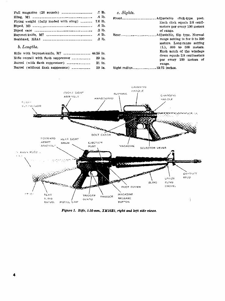
Full magazine (20 rounds) ------------------ .7 lb. C. Sights.Sling, M1 ----------------------------------- .4 lb.~~Sling, Ml- ~.4 lb. ~FrontA__d ___js____a____Adjustable click-type post.Firing weight (fully loaded with sling) _-____- 7.6 lb. Each click equals 2.8 centi-Bipod, M3 ----------------------------------- .6 lb. meters per every 100 metersBipod case ---------------------------------- .2 lb. of range.Bayonet-knife, M7 --------------------------- .6 lb. Rear- _ ___----- ---- __.___ Adjustable, flip type. NormalScabbard, M8A1 M.A.------------------ .3 lb. range setting is for 0 to 300
meters. Long-range settingb. Lengths. (L), 300 to 500 meters.
Rifle with bayonet-knife, M7 .. _____ _ 44.25 in. Each notch of the windagedrum equals 2.8 centimeters
Rifle overall with flash suppressor ___-_-_____ 39 in. per every 100 metersper every 100 meters ofBarrel (with flash suppressor) __________--__ 21 in. range.
Barrel (without flash suppressor) -__________ 20 in. Sight radius---------_---- 19.75 inches.
CAHI:t N G
HANDLEFRONT SIGHT SLIPRING
CHARGINGHANDGUARD HANDLE
r; A!-4
/ / |
_-H ECO1 AInsV / i
SWIVLBOLT CATCI SH
FO)RWARD REAR SIGHT
ASSIST DRUM EJECTION
ASSEMBHL PORT MAGAZINE
~ IN~ C.;~ TRIGGER RELEASESTUD
DUST COVER SWIVEL
c Tt~tw REAR / TRIGGER MAGAZINE
S Ih F G GUARD1 eG RELEASESWIVEL PISTOL GRIP BUTTON
Figure 1. Rile, 5.56-mm, XM16R1, right and left side views .
4

d. Ammunition.Caliber 5.56-mm (complete
round) M193-----------.179 grains.Projectile .______________.55 grains.Types-__________________.Ball (standard)
Tracer (standard)Blank (under development).
e. Operational Characteristics.Muzzle velocity ..________3,150 feet per second
(approx).Muzzle energy
(at the muzzle) --------- 1,300 foot-pounds (approx).Cyclic rate of fire -------_ 700 to 800 rounds per minute.Maximum rate of fire:
Semiautomatic ----_--45 to 65 rounds per minute.Automatic------------ 150 to 200 rounds per minute.Sustained rate of fire__ 12 to 15 rounds per minute.
Maximum range --_------ .2,653 meters.Maximum effective range__460 meters.
f. Terms.Cyclic rate of fire --------- The rate at which a weapon
fires automatically.Sustained rate of fire------Actual rate of fire that a
weapon can continue to de-liver for an indefinite
~'~ length of time without seri-ously overheating.
Maximum rate of fire ------ The maximum number ofrounds the average riflemancan fire in 1 minute, disre-garding hits on the target.
X hi Maximum range ---------- The greatest distance that aweapon can fire.
Maximum effective range__.The greatest distance atwhich a weapon may be ex-pected to fire accurately to
Figure 2. Attaching the bipod. inflict casualties or damage.
S
Chapter 2
MECHANICAL TRAINING
Section I. DISASSEMBLY AND ASSEMBLY
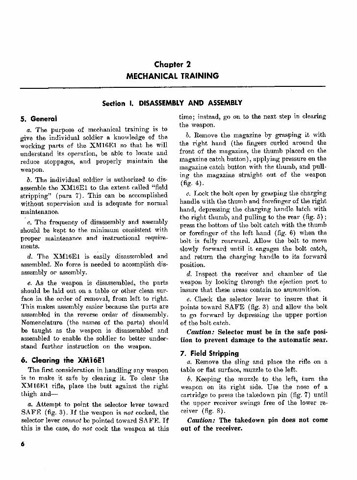
5. General time; instead, go on to the next step in clearingthe weapon.
a. The purpose of mechanical training is togive the individual soldier a knowledge of the b. Remove the magazine by grasping it withworking parts of the XM16E1 so that he will the right hand (the fingers curled around theunderstand its operation, be able to locate and front of the magazine, the thumb placed on thereduce stoppages, and properly maintain the magazine catch button), applying pressure on theweapon. magazine catch button with the thumb, and pull-
ing the magazine straight out of the weaponb. The individual soldier is authorized to dis- fi
assemble the XM16E1 to the extent called "fieldstripping" (para 7). This can be accomplished c. Lock the bolt open by grasping the chargingwithout supervision and is adequate for normal handle with the thumb and forefinger of the rightmaintenance. hand, depressing the charging handle latch with
the right thumb, and pulling to the rear (fig. 5);should be kept to the minimum consistent with press the bottom of the bolt catch with the thumb
should be kept to the minimum consistent with or forefinger of the left hand (fig. 6) when themproper maintenance a ~nd instructional reqire- bolt is fully rearward. Allow the bolt to movements. slowly forward until it engages the bolt catch,
d. The XM16E1 is easily disassembled and and return the charging handle to its forwardassembled. No force is needed to accomplish dis- position.assembly or assembly. d. Inspect the receiver and chamber of the
e. As the weapon is disassembled, the parts weapon by looking through the ejection port toshould be laid out on a table or other clean sur- insure that these areas contain no ammunition.face in the order of removal, from left to right. e. Check the selector lever to insure that itThis makes assembly easier because the parts are points toward SAFE (fig. 3) and allow the boltassembled in the reverse order of disassembly. to go forward by depressing the upper portionNomenclature (the names of the parts) should of the bolt catch.be taught as the weapon is disassembled and Caution: Selector must be in the safe posi-assembled to enable the soldier to better under- tion to prevent damage to the automatic sear.stand further instruction on the weapon.
7. Field Stripping6. Clearing the XMi6E1 a. Remove the sling and place the rifle on a
The first consideration in handling any weapon table or flat surface, muzzle to the left.is to make it safe by clearing it. To clear the b. Keeping the muzzle to the left, turn theXM16E1 rifle, place the butt against the right weapon on its right side. Use the nose of athigh and- cartridge to press the takedown pin (fig. 7) until
a. Attempt to point the selector lever toward the upper receiver swings free of the lower re-SAFE (fig. 3). If the weapon is not cocked, the ceiver (fig. 8).selector lever cannot be pointed toward SAFE. If Caution: The takedown pin does not comethis is the case, do not cock the weapon at this out of the receiver.
6

· tt
Figure S. Selector lever pointing to SAFI7.
Figure 3. Selector lever poi~nting to SAE%

-?e~ ~ Fgr 11 Ro ig te mai
8S~~~ ,X
rro
i "
Figure 4. Removing the magazine.

Figure 5. Pulling the charging handle rearward.
- ~-
K
Figure 6. Locking the bolt open.
9

Figure 7. Pressing the takedown pin to the right.
UPPER LOWER
~~REC. ~~EIE ~ RECEIVER
Figure 8. Breaking the upper receiver away rom the Figure 9. Presing out the receiver pivot pin.
Figure 8. Breaking the upper receiver away from the Figure 9. Pressing out the receiver pivot pin.lower receiver.
10

c. Again using the nose of a cartridge, press Caution: Steps (f) and (g) below should be
the receiver pivot pin (fig. 9). Separate the upper performed only when absolutely necessary forand lower receiver groups (fig. 10) and place the care and cleaning.lower receiver group on the table.
Caution: The receiver pivot pin does not f. Using the index finger of the right hand,
come out of the receiver. push in on the action spring guide assembly.With the nose of a cartridge or the tip of the
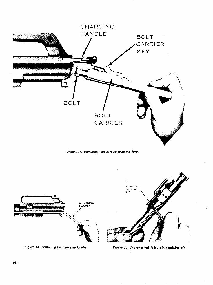
d. Pick up the upper receiver group; keep the firing pin, push down on the buffer retainer.muzzle to the left. Grasp the charging handle, Allow the action spring guide assembly to movepressing in on the latch, and pull to the rear (fig. Allow the action spring gude assembly to move
5) .withdra th blcarefomteeeir. forward slowly until clear of the buffer retainer.5) to withdraw the bolt carrier from the receiver.Grasp the bolt carrier and pull it from the re- Depress the hammer to the rear (downward)
ceiver (fig. 11). When the bolt carrier is removed, sufficiently to allow the action spring guide
the charging handle will fall free of its groove in assembly to clear the hammer. Remove the action
the receiver (fig. 12). Place the receiver on the spring guide assembly and the action spring (fig.
table. 17).Note. The action spring is under pressure and care
e. To disassemble the bolt carrier group, press must be taken in removing it.out the firing pin retaining pin by using the
nose of a cartridge (fig. 13). Elevate the front g. The last parts to be removed are the hand-
of the bolt carrier and allow the firing pin to guards. Place the upper receiver on the table
drop from its well in the bolt (fig. 14). Rotate with the muzzle up. Pull down on the slipring
the bolt until the cam pin is clear of the bolt until the lower lip of the handguard is clear;
carrier key and remove the cam pin by rotating pull out and down on the handguard until the
it 90 degrees (1/4 -turn)' and lifting it out of the upper lip is free of the handguard cap (fig. 18).
well in the bolt and bolt carrier (fig. 15). After Repeat the same operation to remove the second
the cam pin is removed, the bolt can be easily handguard. Considerable pressure must be used toremoved from its recess in the bolt carrier (fig. force the slipring down.16). This completes disassembly of the bolt car- Note. Handguards should not be removed when therier group. Further disassembly of the bolt is upper and lower receiver groups are separated becauseauthorized by the company armorer. of potential damage to the forward assist assembly.
UPPERRECEIVERGROUP
RECEIVERGROUP
Figure 10. Upper and lower receiver groups.
I_! I | l ~~~~~~~~~~~~~~~~~~11
CHARGINGHANDLE BOLT
CARRIER
KEY
BOLT
BOLTCARRIER
Figure 11. Removing bolt carrier Jrom receiver.
FIRING PINRETAININGPIN
CHARGINGHANDLE
Figure 12. Removing the charging handle. Figure 13. Pressing out firing pin retaining pin.
12

BOLT
/ h
CAM PIN
Figure 15. Removing the cam pin.
1 s FIRING PIN
Figure 14. Removing the flring pin.
h. This completes field stripping (fig. 19).Note. Detailed disassembly consists of removing the
remaining operating parts from the lower receiver (fig.20) and is not authorized at user and/or organizationlevel. The individual soldier has no need to disassemblethe weapon beyond field stripping. Only qualified mainte-nance personnel are authorized to remove any otherparts from the weapon.
8. Assembly
To assemble the rifle, reverse the procedures of
disassembly. BOLT
a. To assemble the bolt carrier group, grasp thebolt carrier, key up and to the front, inserting
the bolt into the front of the bolt carrier, insur-
ing that the ejector is down and to the left. Re-place the cam pin into its well and rotate the
cam pin 90 degrees (1/4 -turn) to aline the holes resistance is encountered, rotate pin while insert-
in the bolt and cam pin. Grasp the lugged rim of ing).
the bolt and turn until the cam pin is directly Caution: Do not attempt to spread the slot-beneath the bolt carrier key. Insert the firing ted end of the firing pin retaining pin.
pin through the open end of the bolt carrier and Note. Check for proper assembly by elevating the
seat fully. Insert the firing pin retaining pin (if front of the bolt. If the firing pin drops out, the firing
13

ACTION SPRING GUIDE
ACTIONSPRING
,,..p
Figure 17. Removing the action spring guide assembly and action spring.
14

pin retaining pin is not between the front and rearspool and the bolt carrier group is incorrectly assem-bled.
b. Replace the handguards and be sure that thes HANfDGUARD CAP slipring is fully seated on the lower lip of both
sections of the handguard. Care must be takento prevent damage to the upper and lower lipsand to insure proper seating.
c. Grasp the upper receiver with the carryinghandle up. Place the charging handle into thegroove in the top of the upper receiver. The lugs
-HANDGUARD on the charging handle must be seated in theirgrooves in the receiver. Place the bolt carriergroup into the open end of the receiver, insuringthat the bolt carrier key is in the slot on theunderside of the charging handle and the bolt isforward in the unlocked position. Push forwardon the bolt carrier group and charging handleuntil fully seated.
d. Place the upper receiver group and lowerreceiver group together and reseat the receiver
LIPRING ipivot pin.
e. Insert the action spring guide assembly intothe action spring and push the open end of thespring into the well in the receiver extensionuntil the buffer retainer snaps into position.
f. Cock the hammer and put the selector leverFigure 18. Removing the handguards. on the safe position. Withdraw the takedown pin
FIRING PINRETAINING PIN
FIRING PINRECEIVER
LOWER RECEIVER GROUP PIVOT PIN/ / BIPOBOLT CARRIER
S_-ru1 L BOLT /;_
BUFFER ASSEMBLY S__i|\_____
; CAM PIN CHARGING HANDLE
SLING FORWARD ASSIST UPPER RECEIVER
Figure 19. The XM16E1 field stripped.
15

Figure 20. Lower receiver group.
and close the weapon. Fully seat the takedown (1) SAFE position. Pull trigger. Hammerpin and replace the sling. should not fall.
(2) SEMI position. Pull trigger. The ham-g. A completion of the rifle ion- mer should fall. Hold trigger to rear,sists of checking the operation of the rifle while recock hammer and release trigger.the selector is in the SAFE, SEMI, and AUTO Hammer should transfer from hammerpositions. The following sequence is used for a hooks and disconnect to the hammerrapid, complete check. Anv portion of the check anud sear engagement.may be used alone to determine the operational (3) AUTO position. Pull trigger. Hammercondition of any specific fire selection. Start with should fall. Hold trigger to the rear andthe upper and lower receiver groups in the open recock the hammer. Still holding theposition, the hammer cocked, and the magazine trigger to the rear, push forward on theout. automatic sear. The hammer should fall.
14
Section II. OPERATION AND FUNCTIONING
9. Operationa. Loading the Magazine.
(1) The magazine has a capacity of 20rounds and may be loaded with anyamount up to that capacity. The maga-zine follower has a raised portion gen-erally resembling the outline of a car-tridge.
(2) Cartridges are loaded into the magazineso that the tips of the bullets point inthe same direction as the raised portionof the follower (fig. 21).
b. Loading the Rifle.
(1) With the hammer cocked, place the se-lector lever on SAFE (fig. 3). Themagazine may be inserted with thebolt opened or closed. However, thesoldier should be taught to load theweapon with the bolt open. This willreduce the possibilities of a first-roundstoppage and save the time needed to " _pull the charging handle to the rear.
(2) Hold the stock of the rifle under theright arm with the right hand graspingthe pistol grip, and point the muzzle ina safe direction. With the left hand, Figure 21. Loading cartridges into the magazine.insert a loaded magazine into the maga-zine feedway. Push upward until themagazine catch engages and holds the move the empty magazine from themagazine. Rap the base of magazine weapon. Place the new magazine intosharply with the heel of the hand to the magazine feedway and push up untilinsure positive retention. Depress the fully seated (9b(2)).upper portion of the bolt catch (fig. 22) c. Unloading. To unload the rifle and makewith the thumb of the left hand, allow- it safe, the firer first' places the selector levering the bolt to close, chambering a on safe, presses the magazine catch button andround. If the bolt is closed when the removes the magazine, pulls the charging han-magazine is inserted, pull the charging dle to the rear, inspects the chamber to insure ithandle fully to the rear with the right is clear, locks the bolt carrier to the rear byhand and release it. depressing the lower portion of the bolt catch,
Note. Do'not "ride" the charging handle and returns the charging handle forward. Theforward with the right hand. If the charging rifle is clear only when no round is in the cham-handle is eased forward from the open posi- ber, the magazine is out, the bolt carrier is to thetion, the bolt may fail to lock. If the bolt failsto go fully forward, use the forward assist as- rear, and the selector lever is on the SAFE set-sembly (fig. 1). To operate, strike the forward ting.assist with the heel of the right hand.
(3) The bolt catch will hold the bolt carrier 10. Functioningto the rear after the last round is fired. a. Functioning consists of eight basic steps.To change magazines for reloading, Keep in mind that more than one of these stepspress the magazine catch button and re- takes place at a time. The eight steps are:
17

Figure 22. Depressing the upper portion of the bolt catch.
(1) Firing. trigger and disengaging the notch on(2) Unlocking. the bottom of the hammer. The ham-(3) Extracting. mer is thrown forward by action of(4) Ejecting. the hammer spring. The hammer
strikes the head of the firing pin, driv-(5) Cocking. ing the firing pin through the bolt into(6) Feeding. the primer of the round. The action of(7) Chambering. the rifle is so much faster than human(8) Locking. reaction that it is impossible for the
firer to release the trigger rapidlyb. Functioning in the rifle may be either auto- to
enough to prevent multiple firing.matic or semiautomatic through the use of the ehnrforg itpi necsuar flrTherefore, it; ..........- .....o-salactor '.evr. Cer~tlli dtIferences in tfe opera-i Cvter. '~rai~ii uuiierences in the opera- anism to be installed in the weapon totion of parts take place when the selection is ansm toe istalled i the weapon to
~~~~~~~~~~~~made. ~enable the firer to fire single rounds.In the XM16E1 the disconnect is used
(1) Semiautomatic fire. for this purpose. The disconnect is at-(a) Firing. With a round in the chamber, tached to the trigger and is rotated
the hammer cocked and the selector forward by action of the disconnecton the SEMI setting, the firer pulls spring. When the hammer is cockedthe trigger. The trigger rotates on the by the recoil of the bolt carrier, thetrigger pin depressing the nose of the disconnect engages the lower hook of
18

Figure 23. Firing.
the hammer and holds it until the der between the bolt and bolt carrier,trigger is released. When the trigger causing the bolt carrier to move rear-is released, the disconnect rotates to ward.the rear and down, disengaging the (c) Unlocking. As the bolt carrier moveshammer and allowing it to rotate for- to the rear, the cam track in its upperward until caught by the nose of the surface acts on the bolt cam pin, ro-trigger. This prevents the hammer tating the cam pin and bolt until thefrom following the bolt carrier for-ward and causing automatic fire in line with the locking lugs of the bolt are no longer
~~~~~(fig. 23). ~in line with the locking lugs of thebarrel extension (fig. 25).
(b) Action of the gas. When the primer barrel extension (fig. 25).ignites the powder, the projectile is (d) Extracting. The bolt carrier continues
forced through the barrel. At the same to the rear, carrying with it the bolt.time the gas moves through the barrel By means of the extractor, which isuntil, passing the gas port located on attached to the bolt, the expended car-the upper surface of the barrel (un- tridge is withdrawn from the cham-
der the front sight), a small portion ber. The claw of the extractor is grip-
of the gas passes through the gas port ping the rim of the cartridge, holding
and into the gas tube (fig. 24). The the base of the round against the facegas tube directs the gas into the cylin- of the bolt (fig. 26).
19

Figure 24. Gas tube.
20nts i Lk a OCKINGUNLOCKING
LOCKING
~~~~~~20 ~~~Figure 25. Locking and unlockiing.
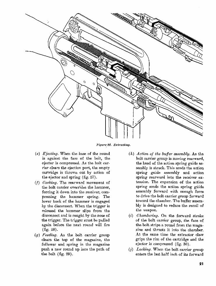
Figure 26. Extracting.
(e) Ejecting. When the base of the round (h) Action of the buffer assembly. As theis against the face of the bolt, the bolt carrier group is moving rearward,ejector is compressed. As the bolt car- the head of the action spring guide as-rier clears the ejection port, the empty sembly is struck. This sends the actioncartridge is thrown out by action of spring guide assembly and actionthe ejector and spring (fig. 27). spring rearward into the receiver ex-
(f) Cocking. The rearward movement of tension. The expansion of the actionthe bolt carrier overrides the hammer, spring sends the action spring guideforcing it down into the receiver, com- assembly forward with enough forcepressing the hammer spring. The to drive the bolt carrier group forwardlower hook of the hammer is engaged toward the chamber. The buffer assem-by the disconnect. When the trigger is bly is designed to reduce the recoil ofreleased the hammer slips from the the weapon.disconnect and is caught by the nose of (i) Chambering. On the forward strokethe trigger. The trigger must be pulled of the bolt carrier group, the face ofagain before the next round will fire the bolt strips a round from the maga-(fig. 28). zine and thrusts it into the chamber.
(g) Feeding. As the bolt carrier group At the same time the extractor clawclears the top of the magazine, the grips the rim of the cartridge and thefollower and spring in the magazine ejector is compressed (fig. 30).push a new round up into the path of (j) Locking. When the bolt carrier groupthe bolt (fig. 29). enters the last half inch of its forward
21
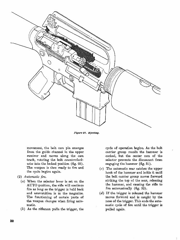
Figure 27. Bjecting.
movement, the bolt cam pin emerges cycle of operation begins. As the boltfrom the guide channel in the upper carrier group recoils the hammer isreceiver and moves along the cam cocked, but the center cam of thetrack, rotating the bolt counterclock- selector prevents the disconnect fromwise into the locked position (fig. 25). engaging the hammer (fig. 31).The weapon is then ready to fire and (c) The automatic sear catches the upperthe cycle begins again. hook of the hammer and holds it until
(2) Automatic fire. the bolt carrier group moves forward(a) When the selector lever is set on the striking the top of the sear, releasing
AUTO position, the rifle will continue the hammer, and causing the rifle tofire as long as the trigger is held back fire automatically (fig. 32).and ammunition is in the magazine. (d) If the trigger is released the hammerThe functioning of certain parts of moves forward and is caught by thethe weapon changes when firing auto- nose of the trigger. This ends the auto-matic. matic cycle of fire until the trigger is
(b) As the rifleman pulls the trigger, the pulled again.
22

NORMAL COCKING
COCKING WHEN TRIGGER IS HELD BACKDURING SEMI-AUTOMATIC FIRING
Figure 28. Cocking.
23

0!
I
Figure 29. Feeding.
24

Figure 30. Chambering.
25

SEMI AUTO SAFE
SEMI AUTO SAFE
Figure 81. Selector lever.
(e) All other portions of the cycle of of the bolt face by action of the maga-operation remain the same as in semi- zine spring. This holds the bolt carrierautomatic fire. group to the rear.
c. The functioning of the rifle through the (2) Removal of the magazine does not re-cycle of operation stops when the trigger is re- lease the bolt carrier group due to theleased or when the magazine is empty. In the force of the action spring holding thelatter case certain actions take place within the face of the bolt tightly against the catch.weapon to tell the firer that he must change To release the bolt carrier group, themagazines. firer must press the head of the bolt
(1) When the last round of a magazine has catch located on the left side of the re-been chambered, the magazine follower ceiver.rises to the top of the magazine and con- Caution: If a new magazine hastacts the bolt stop. As the bolt carrier been inserted and the bolt carriergroup recoils after the last round is group goes forward, the weapon isfired, the bolt stop is forced into the path charged and ready to fire.
26

Figure 32. Automatic sear.
Section III. CARE AND CLEANING
11. Maintenance the direction of the brush while in th(bore.) Remove the brush from the cleanNormal care and cleaning will result in proper rg rod ad dry the bore with clear
functioning of all parts of the weapon. Im- patches. The patches are to be cut intproper maintenance causes stoppages and mal- four equal size patches are to e cut ntfunctions. Only issue-type cleaning materials (fig. swab will be used at on e t n tho33) as authorized in TM 9-1005-249-14 should bore. Do not attempt to retrat the robe utilized. Cleaning materials are carried by the until the swab has been removed (afteirifleman in the section provided on the bipod case. going through the flash suppressor).
a. Cleaning and Lubricating the Barrel. Caution: Cleaning rod is to be sup-(1) Attach a wire brush to the cleaning rod, ported by hand, a section at a time,
dip it in solvent cleaning compound to prevent flexing and damage to the(bore cleaner), and brush the bore thor- rod when starting into the bore.oughly. Brush from the chamber to themuzzle using straight-through strokes (2) Clean the locking lugs in the barrel ex-muzzle using straight-through strokes(fig. 34). Push the brush through the tension, using a small bristle brush.bore until it extends beyond the muzzle. (3) Clean the protruding exterior of the gasContinue this process until the bore is tube in the receiver with the bore brushcoated with compound. (Never reverse attached to a section of the cleaning rod.
27

Figure 33. Cleaning equipment.
I
Figure 34. Cleaning bore with cleaning rod and brush.
28

The top of the gas tube can be cleaned light struck primer and a failure toby inserting the rod and brush in the fire.back of the receiver. The sides and bot- Caution: Do not attempt to removetom of the gas tube can be cleaned from discoloration caused by heat.the bottom of the receiver. Note. A common malfunction is the "freez-
Note. Do not use any type of an abrasive ing" of the bolt carrier key to the gas tube.material to clean the gas tube.
ec. Cleaning and Lubricating the Lower Re-(4) After cleaning, lubricate the bore and ceiver Group.
locking lugs in the barrel extension byapplying a light coat of oil to prevent (1) Cleaning will not require detailed dis-corrosion and pitting. If the handguards assembly of the lower receiver group.have been removed, rub a light coat of Using a clean, dry patch or bristleoil on the surface of the barrel inclosed brush, remove dirt and sand from theby the handguards. lower receiver. Place only one drop of
b. Cleaning and Lubricating the Bolt Carrier oil on each pin and selector lever shaft.Group. for lubrication.
(1) Remove the bolt carrier group from the (2) After extensive use or field exercise,upper receiver group and disassemble. acids caused by perspiration should beClean all parts with a swab dipped in removed from exterior surfaces using asolvent cleaning compound. rag or swab saturated with bore cleaner,
(2) Clean the locking lugs of the bolt, using then wiped dry and a light coat of oila small brush and cleaning solvent. Dry applied.with clean patches and oil lightly.
(3) Clean the bolt carrier key with a bore 12. Preventive Maintenancebrush. A used or worn brush should beused if available, a. Preventive maintenance is the systematic(4) Put only one drop of oil in each hole care, inspection, and servicing of equipment to(4) Put only one drop of oil in each holeon the right side of the bolt carrier and maintain it in serviceable condition, prevent,the open end of the bolt carrier key. Add breakdowns, and assure maximum operationala light coat of oil to all surfaces of the readiness. The operator's role in the performancebolt and bolt carrier. of preventive maintenance service is-
Caution: Excessive oil in the firing (1) To perform the service each day thepin recess of the bolt will result in a rifle is operated.
Interval and sequence No. Operator's daily schedule
Para-Before During After Item to be Procedures graphfiring firing firing inspected refer-
ence
1 Rifle Wipe oil from bore and chamber. 11a.
2 Rifle Retract bolt to assure free move-ment between bolt carrier and gas tube. 11b.
3 Rifle Function check to assure proper op-eration. 8g.
4 Rifle Check magazine for positive retentionand functioning of bolt catch. 10e(2).
5 Rifle Clean and lubricate. Particular atten-tion to clean bolt carrier key. 11b.
Figure 35. Preventive maintenance checeks and services.
29

(2) To assist the organizational mainte- 13. Functioning Checknance mechanics in the performance of
hperiodicEach time the weapon is disassembled andany other scheduled periodic services cleaned, a check should be made to insure thatspecified by pertinent technical manuals. all parts are properly assembled and the mech-
b. Figure 35 gives the specific procedures to anisms are working properly in the SAFE,be performed on the rifle by the operator for SEMI, and AUTO settings.each daily service. Note. For functioning checks see paragraph 8g.
Section IV. STOPPAGES AND IMMEDIATE ACTION
14. Stoppages tion when clearing a stoppage in the XM16E1consists of the following steps:
A stoppage is any unintentional interruptionin the cycle of operation. Immediate action must a. Strike upward on the bottom of the maga-
zine to insure that it is fully seated.be taken to clear the stoppage.b. Pull the charging handle fully to the rear
15. Immediate Action and release it.
Immediate action is the unhesitating applica- c. Strike the forward assist assembly to insuretion of a probable remedy to reduce a stoppage that the bolt is fully seated.without investigating the cause. Immediate ac- d. Attempt to fire the weapon.
Section V. AMMUNITION
16. General 18. Packaging
This section includes available information on Presently there are 20 rounds per carton, andthe types of ammunition used with the XM16E1 36 cartons (720 rounds) per metal box, M2A1;rifle. The types of ammunition are for the pur- 2 metal boxes (1,440 rounds) per wire-bound box.poses indicated.
19. Care and Cleaning17. Classification
a. When necessary to store ammunition in thea. Cartridge, 5.56-mm, ball, M193. The ball open, raise it on dunnage at least 6 inches from
ammunition is a 5.56-mm, center fire cartridge the ground and protect it with a cover, leavingwith a 55 grain, gilding-metal jacketed, lead enough space for circulation of air.alloy core bullet. The primer and case are water- b. Since ammunition and explosives are ad-proofed. The ball round is the basic cartridge versely affected by moisture and high tempera-for field use and has no identifying marks. ture, due consideration should be given to (1)
b. Cartridge. 5.56-mm, tracer, M196. The and (2) below:tracer ammunition has the same basic charac- (1) Do not open boxes until ammunition isteristics as tne ball. it is iclentified by an orange- to be used. Ammunition removed frompainted tip. Its primary uses are for observation airtight containers, particularly in dampof fire, incendiary effect, and signaling. climates, is apt to corrode.
c. Cartridge, 5.56-mm, blank, XM200. The (2) Protect ammunition from high tempera-characteristics of the blank ammunition are not tures and the direct rays of the sun.currently known, as the item is still under de- More uniform firing is obtained ifvelopment. rounds are at the same temperature.
30

c. Do not attempt to disassemble the cartridge mud, moisture, frost, snow, ice, grease, and otheror any of its components. foreign matter. If it gets wet or dirty, it should
d. The use of oil or grease on cartridges is pro- be wiped off at once.hibited. f. Brass cartridge cases are easily dented and
e. Ammunition should be protected from sand, should be protected from hard knocks or blows.
Section VI. DESTRUCTION OF MATERIEL TO PREVENT ENEMY USE
20. General normally may not be authorized items of issue*Destruction of the XM1E1, when subject to the using organization. Of the several meansDestruction of the XM16El, when subject to
capture or abandonment in the combat zone, will of destruction, those most generally applicablebe undertaken by the using unit only when, in are:the judgment of the unit commander concerned, a. Mechanical-requires axe, pick mattock,such action is necessary in accordance with sledge, crowbar, or similar implement.orders of, or policy established by, the army b. Burning-requires gasoline, oil, incendiarycommander. The following priorities should be grenades, or other flammables.followed when destroying small arms weapons:
c. Demolition-requires suitable explosives ora. Breech mechanisms. ammunition (see note).
ammunition (see note).b. Barrel. d. Gunfire-includes artillery, machineguns,
c. Sighting equipment (including infrared). rifles using rifle grenades, and launchers using
d. Mounts. antitank rockets (see note).
21. Methods e. Disposal-requires burying, dumping instreams or marshes, or scattering so widely as
The information which follows is for guidance to preclude recovery of essential parts.only. Certain of the procedures require the use Note. Generally applicable only when the rifle is to beof explosives and incendiary grenades which destroyed in conjunction with other equipment.
31

Chapter 3MARKSMANSHIP TRAINING
Section I. PREPARATORY MARKSMANSHIP
22. General (1) Grasp of the left hand. The rifle shouldrest in the V formed by the thumb andWith very few exceptions, the preparatory rein the V formed by the thumb and
marksmanship training for the XM16E1 is identi- forefinger of the hand, and liecal to that for the M14 (FM 23-71) and M14A2 across the heel of the hand. The grip on(FM 23-16) rifles. With any weapon, the foun- the handguard should be relaxed but, atthe same time, exert a slight rearwarddation upon which good marksmanship is built the same time, exert a slight rearwardpressure. The handguards are gripped atis preparatory training. Here the rifleman learns p t. he -a point which suits both the conforma-the fundamentals which must be applied through-
is . .tion of the firer's body and the locationout his training and in combat. This chapter is of the target. If the target is high, thedevoted to the training necessary to produce an left hand is moved closer to the body,effective rifleman.
thereby rising the muzzle of the weapon.Conversely, if the target is low, the left23. The Integrated Act of Shooting hand is moved forward, causing a cor-
a. Aiming. responding drop in the muzzle of the.. . ................. .weapon. The left wrist should be as(1) In aiming, the firer is concerned with straight as possble, an d the left elbow
correctly pointing his rifle so that the straight as possible, and the left elbowbullet will hit the target when he fires.To do this, he must have the rear sight, weapon, or as close to this position as
o do ts, he musfron t sight, and thave target, or aim- the conformation of the firer's body willthe front sight, and the tvarget, or aim-ing point, in their proper relationship.This relationship is known as sight pic- (2) Rifle butt in the pocket of the shoulder.ture. Sight picture involves two ele- The firer must place the butt of thements: sight alinement and placement of stock firmly into the pocket formed inthe aiming point. his right shoulder (fig. 37). The proper
(placement of the butt of the stock les-(2) The techniques of aiming the XM16E1 sens the effect of recoil, helps steady therifle are the same as for the M14 rifle weapon, and prevents the butt of theweapon, and prevents the butt of the(FM 23-71). stock from riding up on the shoulder.
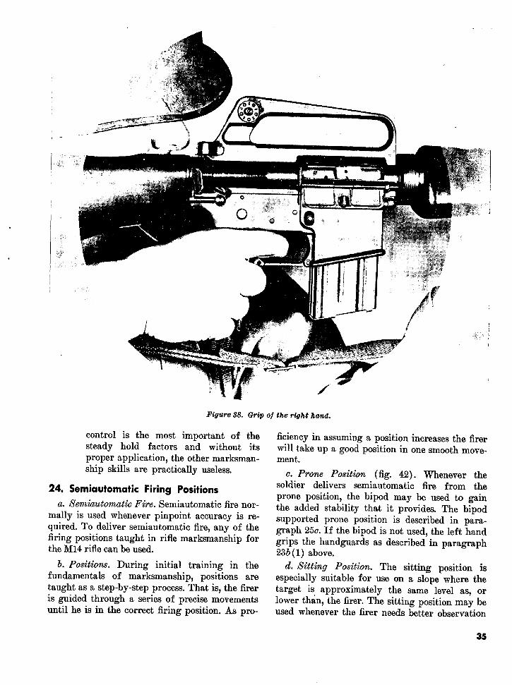
.. -V y .- . t..y ..l i .VI .1l IUbe, linqUte (3) Grip of the right hand. The right handof holding the weapon as steady as possible while grasps the pistol grip so that the pistolobtaining a sight picture and firing. There are grip rests in the V formed by the thumbeight factors which affect holding a weapon and forefinger (fig. 38). The forefingersteady. These factors are basically the same for (trigger finger) is placed on the triggerall firing positions; however, the precise manner so that daylight shows between the sidein which they are applied differs slightly with of the stock and the finger. The remain-the various firing positions. This discussion of ing fingers are wrapped tightly aroundthe steady hold factors will be as they apply to the pistol grip. A firm rearward pres-the semiautomatic firing positions. sure must be exerted by the right hand
32
u/,
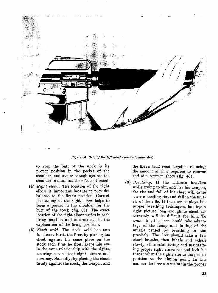
Figure 36. Grip of the left hand (semiautomatic fire).
to keep the butt of the stock in its the firer's head recoil together reducingproper position in the pocket of the the amount of time required to recovershoulder, and secure enough against the and aim between shots (fig. 40).shoulder to minimize the effects of recoil. (6) Breathing. If the rifleman breathes
(4) Right elbow. The location of the right while trying to aim and fire his weapon,elbow is important because it provides the rise and fall of his chest will causebalance to the firer's position. Correct a corresponding rise and fall in the muz-positioning of the right elbow helps to zle of the rifle. If the firer employs im-form a pocket in the shoulder for the proper breathing techniques, holding abutt of the stock (fig. 39). The exact sight picture long enoughto shoot ac-location of the right elbow varies in each currately will be difficult for him. Tofiring position and is described in the avoid this, the firer should take advan-explanation of the firing positions. tage of the rising and falling of the
(5) Stock weld. The stock weld has two muzzle caused by breathing to aimfunctions. First, the firer, by placing his precisely. The firer should take a fewcheek against the same place on the short breaths, then inhale and exhalestock each time he fires, keeps his eye slowly while establishing and maintain-in the same relationship with the sights, ing proper sight alinement and lock hisassuring a consistent sight picture and throat when the sights rise to the properaccuracy. Secondly, by placing the cheek position on the aiming point. In thisfirmly against the stock, the weapon and manner the firer can maintain the proper
33

Figure 37. Rile butt in the pocket of the shoulder.
attitude of relaxation, (7) below, without the sight picture is not correct, the firer
exerting any muscle tension to move the should move his body until a relaxed
rifle to the aiming point. Apply pressure position and the desired point of aim are
on the trigger until the weapon fires. If achieved. Muscle tension should not be
the weapon does not fire in approxi- used to hold the weapon in the seri-
mately 10 seconds, he should repeat the automatic firing positions.
cycle above because his vision will blur (8) Trigger control. Trigger control is the
after that time. independent action of the forefinger on
(7) Relaxation. The soldier must learn to the trigger. The forefinger should con-
relax as much as possible in the various tact the trigger at some point between
firing positions. Undue muscle strain or the fingertip and the second joint of the
tension causes trembling which is trans- finger. Since the trigger must be brought
mitted to the weapon. If he finds that straight to the rear, the finger must not
a particular position causes excessive touch the side of the stock as this will
strain, he should vary the position cause pressure to be applied at a slight
slightly until the cause of the strain has angle rather than straight to the rear
been eliminated. The firer must use re- (fig. 41). Side pressure on the rifle, no
laxation to determine that he has a nat- matter how slight, will tend to pull the
ural position. This is accomplished by sights off the aiming point. Correctly ap-
relaxing when in position and checking plied pressure on the trigger causes no
to see if the sight picture is correct. If movement on the rifle barrel. Trigger
34
fif:.; 1_ 1 11t ;:;;/
Figure 38. Grip of the right hand.
control is the most important of the ficiency in assuming a position increases the firersteady hold factors and without its will take up a good position in one smooth move-proper application, the other marksman- ment.ship skills are practically useless. c. Prone Position (fig. 42). Whenever the
24. Semiautomatic Firing Positions soldier delivers semiautomatic fire from theprone position, the bipod may be used to gaina. Semtiautomatic Fire. Semiautomatic fire nor- the added stability that it provides. The bipod
mally is used whenever pinpoint accuracy is re- supported prone position is described in para-quired. To deliver semiautomatic fire, any of the graph 25c. If the bipod is not used, the left handfiring positions taught in rifle marksmanship for grips the handguards as described in paragraphthe M14 rifle can be used. 23b (1) above.
b. Positions. During initial training in the d. Sitting Position. The sitting position isfundamentals of marksmanship, positions are especially suitable for use on a slope where thetaught as a step-by-step process. That is, the firer target is approximately the same level as, oris guided through a series of precise movements lower than, the firer. The sitting position may beuntil he is in the correct firing position. As pro- used whenever the firer needs better observation
35

Figure 39. Right elbow.
than he can get from the prone position. The tion of his left shin, places the butt offirer should use the variation of the sitting po- the stock into the pocket formed in hissition which best fits the conformation of his right shoulder, and takes the proper gripbody. on the pistol grip with his right hand.
The firer locks his right elbow on the in-t(1) O hpen-legged sitting position. To get side of his right knee and exerts a slightinto the open-legged sitting position, the
rearward pressure with his right hand.firer initially faces the target as whene itTo complete the position, the firer ob-getting into the prone position, then ex- a stock weld and relaxes (2, fig.
L-1 * L.... . I. tains a stock weld and relaxes (2. fig.IjaIies a La£-I-IgIlitUe aIlu bjfeUtus Ills 43).
feet well apart. He removes his righthand from the pistol grip and sits down, (2) Cross-ankle sitting position (fig. 44).breaking his fall with his right hand To get into the cross-ankle sitting posi-(1, fig. 43). He slides his buttocks well tion, the firer first sits down in the man-to the rear and points his toes inward, ner prescribed for the open-legged sit-allowing the weight of his legs to rest ting position. He then crosses his lefton the inside of his heels. The firer bends ankle over his right ankle. The firerhis body forward from the hips and places his left upper arm across theplaces his left upper arm on the flat por- shin-bone of his left leg. With his right
36

Figure 40. Stock weld.
hand, he positions the butt of the stock places his left upper arm against theinto the pocket formed in his right shinbone of his left leg. With his rightshoulder. He places his right elbow so hand, he places the butt of the stockthat his right upper arm is in contact into the pocket in his right shoulderwith the shinbone of his right leg. To and takes the proper grip on the pistolcomplete the position, the firer obtains grip. The firer lowers his right elbow soa stock weld and relaxes. This firing po- that his right upper arm is against thesition can be adjusted for a particular shinbone of his right leg. To completeindividual by varying the distance the the position, the firer obtains a stockfeet are extended from the body. weld and relaxes.
(3) Cross-legged sitting position (fig. 45). (4) Comparison of the sitting positions. InTo get into the cross-legged sitting posi- the open-legged sitting position, thetion, the firer first sits down in the man- body comes into contact with the groundner prescribed for the open-legged at three distinct points-the heel of eachsitting position. He then crosses his left foot and the buttocks. In the cross-leg over his right leg and draws both of ankle sitting position, the body comeshis feet up close to his buttocks. He into contact with the ground at two
37

Figure 41. Position o!f the trigger finger.
ai _- '
_ t
Figure 42. Prone position (without bipod).
38
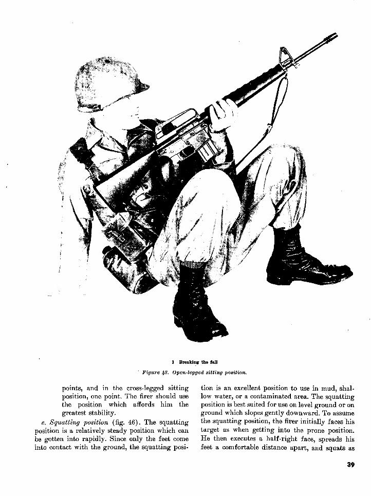
1 Breaking the fall
Figutre ]s3. Open-legged sitting position.
points, and in the cross-legged sitting tion is an excellent position to use in mud, shal-position, one point. The firer should use low water, or a contaminated area. The squattingthe position which affords him the position is best suited for use on level ground or ongreatest stability. ground which slopes gently downward. To assume
e. Squatting position (fig. 46). The squatting the squatting position, the firer initially faces hisposition is a relatively steady position which can target as when getting into the prone position.be gotten into rapidly. Since only the feet come He then executes a half-right face, spreads hisinto contact with the ground, the squatting posi- feet a comfortable distance apart, and squats as
39
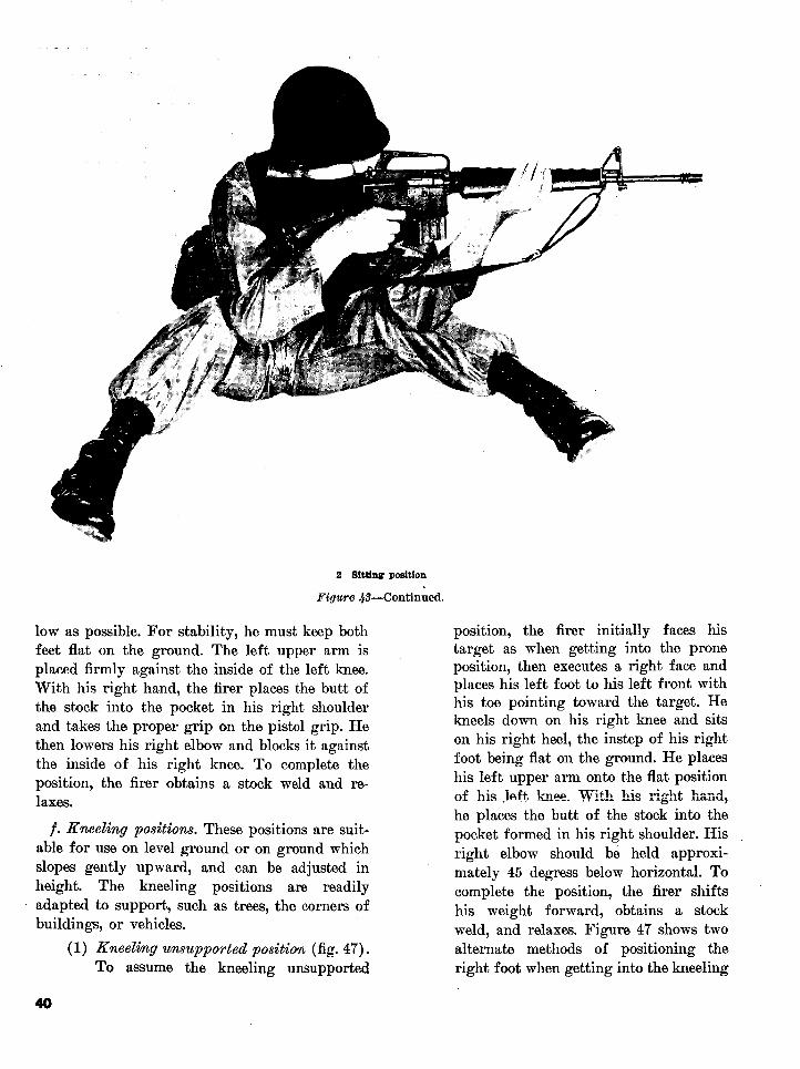
2 Sitting position
Figure 48-Continued.
low as possible. For stability, he must keep both position, the firer initially faces hisfeet flat on the ground. The left upper arm is target as when getting into the proneplaced firmly against the inside of the left knee. position, then executes a right face andWith his right hand, the firer places the butt of places his left foot to his left front withthe stock into the pocket in his right shoulder his toe pointing toward the target. Heand takes the proper grip on the pistol grip. He kneels down on his right knee and sitsthen lowers his right elbow and blocks it against on his right heel, the instep of his rightthe inside of his right knee. To complete the foot being flat on the ground. He placesposition, the firer obtains a stock weld and re- his left upper arm onto the flat positionlaxes. of his lft knee With hiso right hand,
he places the butt of the stock into thef. Kneeling positions. These positions are suit- pocket formed in his right shoulder. His
able for use on level ground or on ground which right elbow should be held approxi-slopes gently upward, and can be adjusted in mately 45 degress below horizontal. Toheight. The kneeling positions are readily complete the position, the firer shiftsadapted to support, such as trees, the corners of his weight forward, obtains a stock
buildings, or vehicles. weld, and relaxes. Figure 47 shows two(1) Kneeling unsupported position (fig. 47). alternate methods of positioning the
To assume the kneeling unsupported right foot when getting into the kneeling
40

the conformation of his body. tion, the firer initially faces his target, thenexecutes a right face and spreads his feet a com-
(2) Kneeling sup ported position (fig. 48). fortable distance apart. With his left hand, theTo get into the t kneeling supported posi- firer grips the handguards. He positions his lefttion, the firer first gets into the kneeling elbow as nearly under the rifle as possible. Withunsupported position. He then shifts his his right hand, he places the butt of the stockweight forward and allows his left into the pocket in his right shoulder, then takesshoulder, left arm, and left leg to come the proper grip on the pistol grip. The firerinto contact with the support. The rifle holds his right elbow approximately horizontal,must not touch or rest on the suppport, or slightly lower, to provide a good pocket in hissince the contact of the weapon against right shoulder and to avoid canting the weapon.the support would slow recovery be- A strong rearward pressure is exerted with histween shots and limit the firer's ability right hand and arm (he holds most of the weightto rapidly shift his point of aim. of the rifle with his right hand and arm). To
g. Standing position (fig. 49). The standing complete the position, the firer shifts his feetposition can be used effectively to engage targets until he is aiming naturally at the target andat ranges less than 100 meters when no other distributes his weight evenly on both of his hips,position can be assumed. It is the least stable of obtains a stock weld, and relaxes.
41

Figure 45. Cross-legged sitting position.
A. Foxhole Position (fig. 50). The foxhole posi- fundamental of automatic rifle marks-tion is the same when using semiautomatic fire manship. Without the proper firing posi-as when using automatic fire, and it is discussed tion, it is impossible for the rifleman toin paragraph 25d. The bipod may be used to gain achieve consistent hits on the targetadded stability. during firing. After the first round of
i. Semiautomatic Fire Coaching Positions. As a burst has been fired, a correct sighta general rule, the coach's position is similar to picture is difficult to maintain. There-that of the firer. The coach should locate himself fore, to continue hitting the target within relation to his firer in a manner which will the remaining rounds in a burst, thepermrit. ohbservatiAof th firr's applcato of Ithe firer must maintain the correct firing
steady hold factors. The coach should exercise position. A burst of automatic fire iscare not to place himself so far forward of his defined as a series of shots fired fromfirer as to be in the path of the ejected cartridge an automatic weapon by one press of thecasings. trigger.
25. Automatic Firing Positions (2) There are three positions used with the
a. General. XM16E1 rifle when using automatic(1) Position is the single most important fire. These are the bipod supported
42

A O
Figure 46. Squatting position.
prone, bipod supported foxhole, and (2) Right elbow. The location of the right.r lerarm positions. elbow is important because it provides
balance to the firer's position. Connectb. Steady Hold. Steady hold for the automaticfiring positions is essentially the same as for the form a pocket in the shoulder for thesemiautomatic firing positions discussed in para- butt of the stock and causes thegraph 23b, except for the following: shoulders to be level. The right elbow
(1) Left arm and grip of the left hand. The should be placed on the ground with theleft hand grips the forward edge of the right upper arm forming an angle asmagazine feedway, the fingers of the left near to 90 degrees with the ground ashand on the right side of the feedway, is consistent with the shoulders beingand the thumb on the left side (fig. 51).The left hand exerts a firm pressure (3) Breathing. When firing automatically,rearward to help keep the butt of the the firer must learn to exhale and inhalestock into the pocket in the right after burst developing a rhythm duringshoulder and to increase ground pressure firing.on the bipod legs, thus minimizing muz- (4) Muscular tension. Contrary to the neces-zle climb. sity of relaxation in semiautomatic rifle
43

Figure 47. Knecling unsupported position.
firing, muscular tension (of parts of the (5) Trigger control. Trigger control is thefirer's body) is a necessary steady hold independent action of the trigger fingerfactor. This can be accomplished only pressing the trigger straight to the rearby tensing t-he mllseleos of the upper until tlhe desired inumber of rounds havearms. The stronger the pressure applied been fired in a burst of automatic fire,to the weapon by the tensing of the then releasing the trigger. The firermuscles of the upper arms (all other must be taught to press the trigger in a
factors being correctly applied), the manner that will permit him to fire aless dispersed will be the rounds in a short burst (2 or 3 rounds). The triggerburst of automatic fire. Although the finger is placed on the trigger at amuscles tensed are primarily those in his point between the fingertip and secondupper arms, the firer will experience a joint of the finger (fig. 41). The triggercertain tensing of his abdominal muscles. finger should not touch the side of the
44

ir vContined.2
Figure 41-Continued.
pistol grip as this will cause pressure forward, breaking his fall with histo be applied at a slight angle rather right hand well forward of his rightthan straight to the rear. Such pressure, knee, and on line with his right kneeno matter how slight, will disturb the and his target (3, fig. 52). He extendsweapon. his left arm forward and places the
rifle on the ground and lowers himselfc. Bipod Supported Prone Position. onto his left side and elbow (4, fig. 52).
(1) The bipod supported prone position is He places the butt of the stock into thethe most stable position and should be pocket in his right shoulder (fig. 37)used whenever possible. To get into the with his right hand, and then takes thebipod supported prone position, the firer proper grip on the pistol grip (fig. 38),initially stands facing his target, hold- lowering his right elbow to the ground.ing the rifle with his left hand on the The firer takes the proper grip on thehandguards, his left arm thrust forward; magazine feedway with his left handhis right hand grasps the pistol grip, and (fig. 51). The firer's legs should bethe butt of the stock is held against his spread a comfortable distance apart, andright hip (1, fig. 52). The muzzle of his heels should be as close to the groundthe weapon is pointed slightly up and as the conformation of his body will per-down range. The firer spreads his feet mit. For maximum stability, his bodya comfortable distance apart and drops should be directly behind the weapon. Toto his knees, removing his right hand complete the position, the firer obtainsfrom the weapon (2, fig. 52). He falls a stock weld (5, fig. 52).
45

Figure 1/8. The kneeling supported position.
(2) The coach initially takes his position When the firer's body is in the correctthree steps to the rear of the firer. From relationship with his rifle, the coachthis position, the coach tells the firer moves forward and checks the firer'swhich way to move to obtain correct legs and feet. Using the steady holdbody alinement. Correct body alinement factors as a guide, the coach checks theis achieved when the firer's body is di- other characteristics of the firer's posi-rectly behind his weapon and an imag- tion. Having accomplished this, theinary line will pass down the long axis coach will move to his initial positionof the weapon, across the firer's right three steps to the rear of the firer andshoulder and over his right buttock. recheck the firer's body alinement. The
46

Figure 49. Standing position.
47

!i! ¸ S~~~ K~fi1 L, I
Figure 50. Foxhole position (without bipod).
coach will then get into the coaching e. Underarm Position.position on the right side of the firer and (1) The underarm firing position fi. 54continue to observe the firer's application is used to engage targets at close ranges,
is used to engage targets at close ranges,of the steady hold factors. during the assault, or any time the rifle-d. Bipod Supported Foxhole Position. man is required to fire while moving. To
get into the underarm firing position, the(1) The bipod supported foxhole position firer initially stands facing his target as
(fig. 53) is used whenever defensive he would in the bipod supported pronepositions have been prepared. To assume position. He then spreads his feet ap-the bipod supported foxhole position, proximately shoulder width apart andthe firer moves to the foxhole and places takes one step forward with his lefthis rifle alongside it. The firer enters foot. The weight of his body should bethe foxhole, adding or removing dirt or equally distributed on both of his feet,sandbags to adjust the foxhole to his and his knees should be slightly flexedheight. The firer then grasps his rifle and as in a boxer's stance. The butt of theplaces his chest against the forward as in a boxer's stance. The butt of the
wall of the foxhole, keeping the muzzle stock is positioned as nearly under theof his weapon pointed slightly up and arm pit as the conformation of his body
down range. For maximum stability, the will allow. His right arm is lowered sofirer braces the bottom of his right foot that the butt of the stock is held firmlyagainst the back of his foxhole. Placing against his side by his upper arm. Thethe bipod of his rifle on the ground for- left hand should grip the handguardsward of his foxhole, the firer grips his firmly, and the left arm should be ex-weapon the same way he would in the tended a comfortable distance forwardbipod supported prone position. to permit guiding the muzzle of the rifle
(2) The coach checks the firer's position, in all directions. The muzzle of theusing the steady hold factors as a guide, weapon should be slightly depressed toand then gets into the coaching position minimize overshooting the target, make(the same as for the bipod supported maximum use of any ricochets, and ad-prone position). just fire onto the target through observ-
48

/ A
Figure 51. Left arm and grip of the left hand (automatic fire).
ing the strike of the bullets on the (3) The underarm firing position permitsground. The right hand grips the pistol the firer to engage targets in any direc-grip firmly. grip ~firmly.tion. To do this, the firer whirls to face
(2) The coach, arms extended and palms out, his target by pivoting on the ball of hispositions himself two steps behind his dfirer. This enables the coach to stabilize lead foot and stepping in the new direc-his firer in the event the firer's position tion with his rear foot.becomes unbalanced.
49
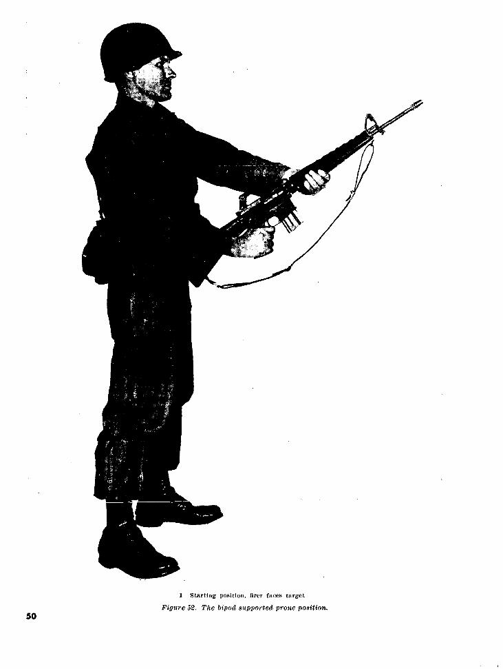
1 Starting position, firer faces target
Figure 52. The bipod supported prone position.50
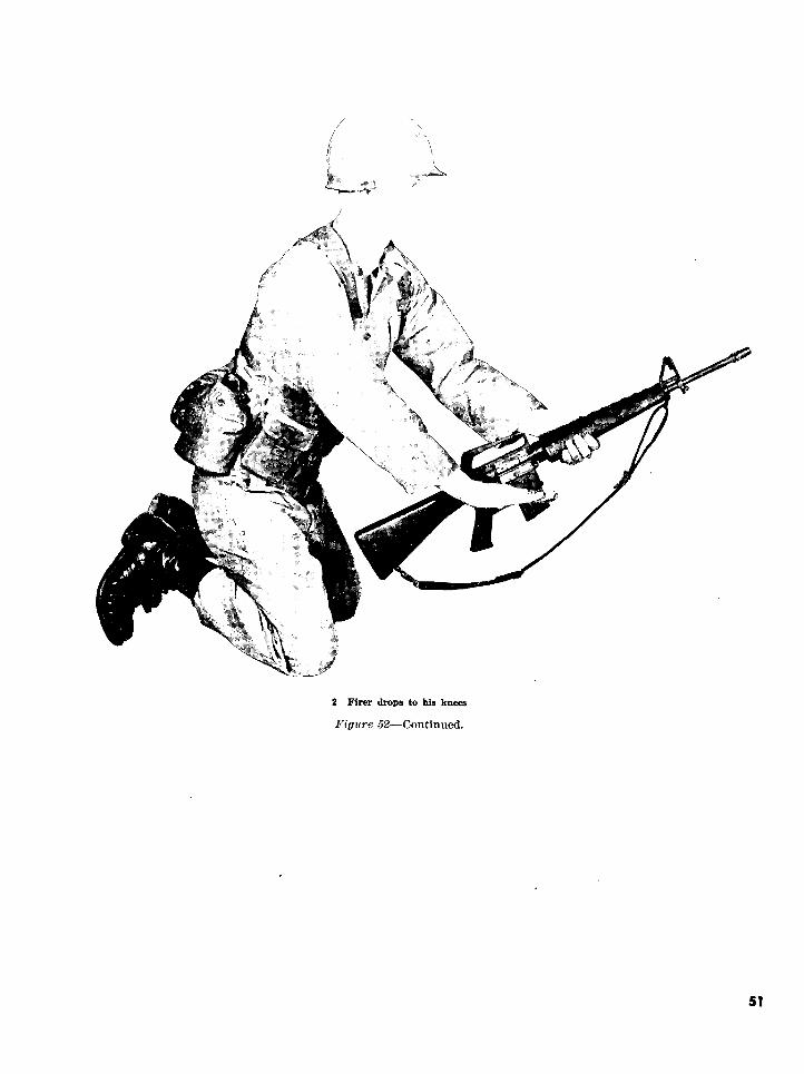
r r^ a
r ;E r S z; i
2 Firer drops to his knees
Figure 52-Continued.
51

3 Firer falls forward
Figure 52-Continued.
Ws
4 Firer rolls over on left side and elbow
Figure 52-Continued.
52

5 Proper position
Figure 52-Continued.
_/I
Figure 53. The bipod supported foxhole position.
53
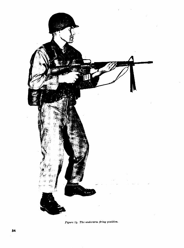
Figure 54. The underarm firing position.
54

Section II. AUTOMATIC FIRE
26. General get; e.g., bunker apertures, windows,
a. Automatic fire is the firing of two or more and single enemy personnel.consecutive rounds without releasing the trigger. (2) Automatic fire. Automatic fire is em-Bursts of two or three rounds are usually fired ployed-to insure minimum dispersion. The rifleman must (a) When engaging enemy formations atunderstand the nature of automatic fire and the ranges out to 460 meters.contracts between automatic and semiautomatic (b) When engaging large point targets
such as crew-served weapon emplace-(1) Semiautomatic fire. Semiautomatic fire ments, unarmored vehicles, and open-
is employed where the range to the tar- ings in buildings out to ranges of 460get is in excess of 460 meters, or in any meters.situation where a high degree of accu- (c) To attain fire superiority when war-racy is required to hit a small point tar- ranted by the tactical situation.
*1$0
Figure 55. Proper method of carrying magazines.
55

Figue 56. Withdrawing magazine from the ammunition pouch (right side).
b. As pointed out in the explanation of the is limited by the capacity of the magazine. Toimportance of position stability, autonatic filre attain a neavy volume of fire, e111 ri.lelliall Muswill not be as accurate, per round fired, as semi- be able to change the magazine in 4 to 5 seconds.automatic fire. This decreased accuracy must be This level of proficiency can only be attainedcompensated for by the delivery of a heavy vol- through thorough and intensive training in theume of fire. A heavy volume of fire is attained fundamentals of automatic fire.in machinegun fire where ammunition is belt-fedand requires no interruption of fire for reload- e. Automatic fire training develops proficiencying. However, with a magazine-fed rifle, volume in the rapid, systematic handling and changingof fire is governed by the rifleman's ability to of magazines. This training insures maximumload and change magazines. Sustained rifle fire effective use of the rifle by the firer.
56

ss
Figure 57. Withdrawing magazine from ammunition pouch (left side).
27. Fire Distribution a heavy volume of fire between the known orsuspected flanks of a target. The rifleman must
a. General. The rifleman must be trained to attempt to place fire within the area of such adeliver fire at targets which have one or more target. It should be strongly emphasized that theselected aiming points. When fire is delivered at inability to see enemy personnel or positionsone aiming point, it is called concentrated fire; should not be a reason for failure to fire into anwhen it is delivered at more the one aiming area if there is reason to suspect the presence ofpoint, it is called distributed fire. a covered or concealed target.
b. Concentrated Fire. Concentrated fire is firedirected at a specific point which requires a high 28. Magazine Handlingdegree of accuracy. Rifle marksmanship training a. Magazines are placed into each ammunitionhas taught the soldier to think principally in pouch with the open end of the magazine down,terms of concentrated fire; he must now be long portion toward the body (fig. 55). Thistaught to apply the integrated act of automatic method of placing the magazines into the am-rifle shooting to distribute, as well as to concen- munition pouches enables the firer to quicklytrate his fire, remove the magazines.
c. Distributed Fire. Distributed fire is fire in b. Removing a magazine from the ammunitiondepth and width so that a target is effectively pouch is the same whether using the right orcovered. The object of distributed fire is to place left hand. To remove a magazine from the pouch,
57

Figure 58. Rotating the hand and wrist (right side).
grasp the magazine with the thumb on the long with his right forefinger (fig. 62) and allowingedge and the first and second fingers on the short the magazine to drop, under its own weight, outedge (figs. 56 and 57). Withdraw the magazine of the weapon.from the ammunition pouch and extend the arm b. Right-Side Load. To load a magazine fromforward, rotating the hand and wrist (figs. 58
the right side, the rifleman uses his right hand.and 59) so that the magazine will be in position After the empty magazine has been removed(open end up and long edge to the rear) to load
~intr~ t9 we n (fiac O gncl P1' .l from the weapon, he secures and loads the nextinft fbha wrannn (fiq AO anrd A I T1 n mTgnA7.zinp,.. -- ........ magazine into the weapon. To chamber a round,is loaded into the weapon by inserting the maga- he depresses the top of the bolt catch with thezine straight up into the magazine feedway untilit is seated. thumb of his left hand (fig. 63), releasing the
bolt. If the bolt was not open when the loadedmagazine was inserted into the weapon, the firer
29. Magazine Changing must pull back on and release the charging han-a. Removing the Empty Magazine. When the die with his right hand to chamber a round. The
ammunition in the magazine in the rifle has been left hand should never be taken away from theexhausted, the firer removes the magazine from weapon when loading the weapon from the rightthe weapon by pressing the magazine catch button side.
58
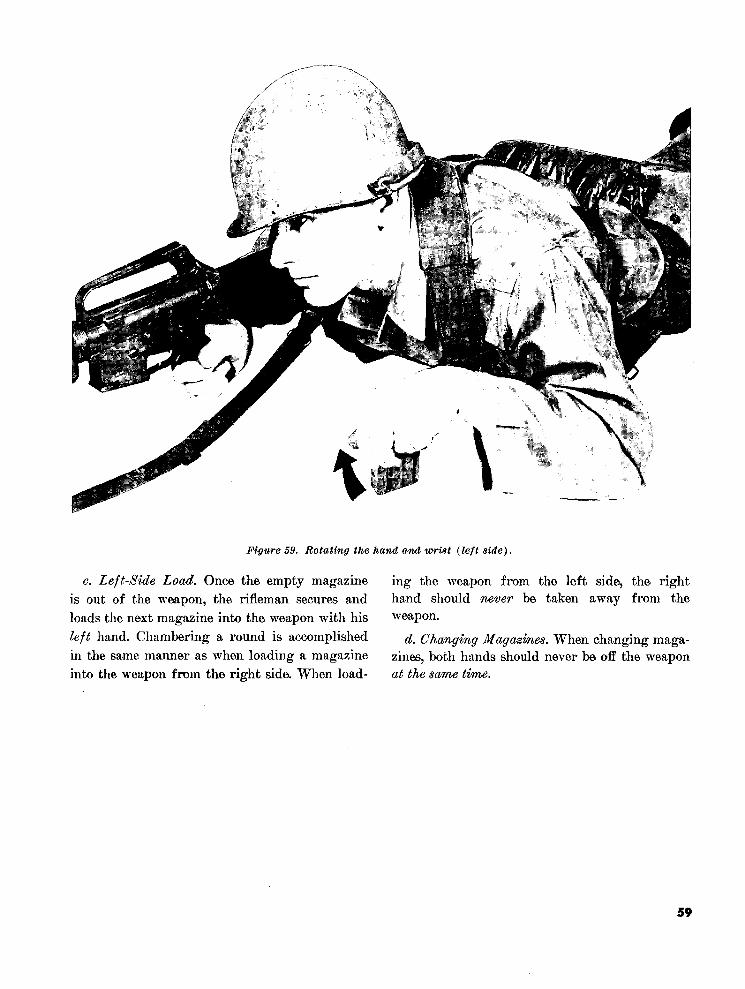
Figure 59. Rotating the hand and wrist (left side).
c. Left-Side Load. Once the empty magazine ing the weapon from the left side, the rightis out of the weapon, the rifleman secures and hand should never be taken away from the
loads the next magazine into the weapon with his weapon.
left hand. Chambering a round is accomplished d. Changing Magazines. When changing maga-in the same manner as when loading a magazine zines, both hands should never be off the weaponinto the weapon from the right side. When load- at the same time.
59
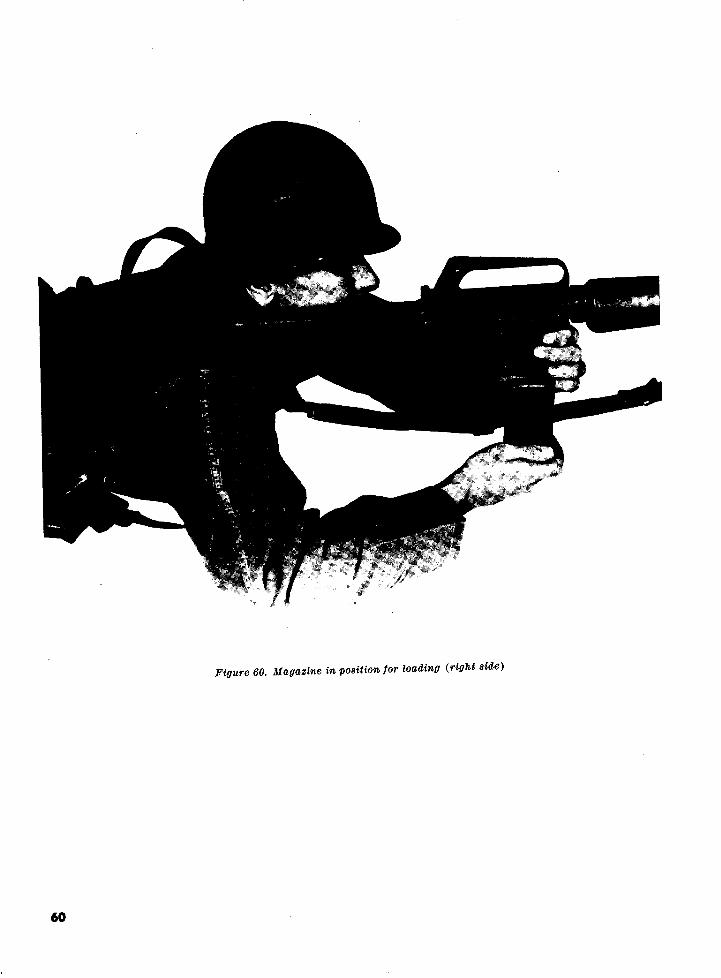
Figure 60. Magazine in position for loading (right side)
60
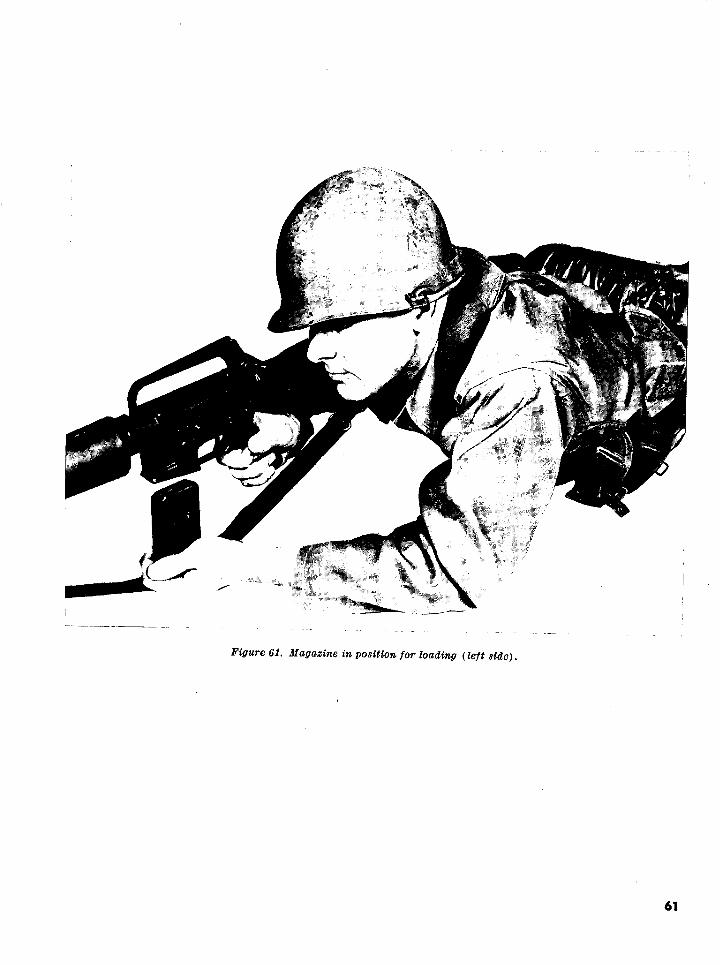
I%
Figure 61. Magazine in position for loading (left side).
61

Figure 62. Releasing the magazile.
62
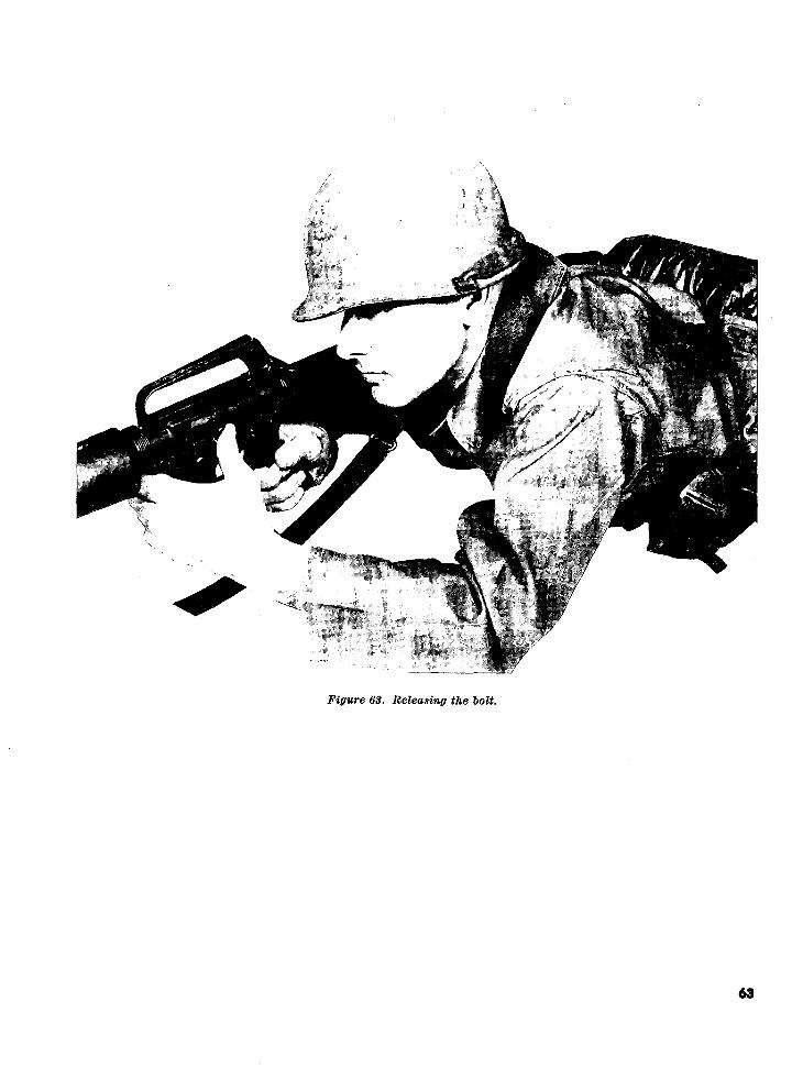
Figure 63. Releasing the bolt.
63

Chapter 4SIGHT ADJUSTMENT AND BATTLESIGHT ZERO
Section I. SIGHT ADJUSTMENT
30. General
Following fundamentals training, the soldiermust zero his weapon. In order to accomplishthis, the soldier must first learn the operation ofthe 'sights, the use of the elevation and windagerule, and how to compute sight changes.
31. The Sights
The sights of the XM16E1 rifle are adjustablefor both elevation and windage. Windage adjust-ments are made on the rear sight; elevation ad-justments on the front sight.
a. The rear sight consists of two apertures (fig.64) and a windage drum with a spring loadedstud (fig. 65). The aperture marked L is usedfor ranges from 300 to 500 meters, and the un-marked aperture for ranges from 0 to 300 meters.Adjustments for windage are made by pressingin on the spring loaded stud with a sharp instru-ment, or the tip of a cartridge, and rotatingthe windage drum in the desired direction. Figure 64. Rear sight apertures.
b. The front sight consists of a rotating sightpost with a spring loaded stud (fig. 66). Adjust- during fundamental training, the precise locationments are made by using a sharp instrument, or of a shot group on the target is unimportantthe tip of a cartridge. To raise or lower the front since it is the size of the shot group, not thesight posts, depress the spring loaded stud and location, that governs the proficiency of the firer.rotate the post in the desired direction.
c. During training in marksmanship funda- 32. Elevation and Windage Rulementals all firing exere~iseS ~ s hou p ld 1 Otec1- Thonne elevation and windage rule states thatwith the rear sight of the weapon centered and one click of elevation or windage will move theset on the short range aperture. The front sight strike of a bullet a specific distance at a specificpost should be set at 24 clicks from its lowest range. At a range of 25 meters, one click ofposition. This setting should not be changed either elevation or windage on the sights of theuntil the firer is able to fire tight shot groups. XM16E1 rifle will move the strike of the bulletThe reason for this is twofold: first, untrained approximately .7 centimeters. To compute thefirers will tend to focus their attention on manip- distance one click will move the strike of a bulletulating the sights rather than learning to prop- at any given range, multiply the range in hun-erly apply marksmanship fundamentals. Second, dreds of meters times 3. For example, to compute

Figure 65. Windage drum.
the distance one click of elevation or windagewill move the strike of the bullet at a range of250 meters, multiply 2.5 by 3. The answer in this . . . i Acase is 7.5 centimeters. :
33. Sight Changes Figure 66. Front sight.a. To make sight changes, the firer first locates
the center of his shot group and then determines b. To raise the strike of the bullet, the firerthe distance between it and the desired location. must rotate the front sight post in the directionAn error in elevation is measured vertically, of the arrow marked UP (stamped on the frontwhile a windage error is measured horizontally. sight base); thus, the strike of the bullet isThese distances are converted to clicks by using raised but the post is lowered. Reverse the direc-the elevation and windage rule. As a general tion of rotation to move the strike of the bulletrule, bold adjustments will prove more advanta- down. To move the strike of the bullet to thegeous to the firer. For example, if there is a right, rotate the windage drum the desiredquestion whether to move two or three clicks, the amount of clicks clockwise (in the direction offirer normally should make the adjustment re- the stamped R). Reverse the direction of rota-quiring the greater number of clicks. tion to move the strike of the bullet to the left.
Section 1. BATTLESIGHT ZERO
34. Principles of Zeroing on the range to the target. The greater the dis-tance a bullet travels before impact, the higher
a. In order to understand the principles ofbullet travels before impact, the higherzeroing, the soldier should have a basic knowl-ravel i its trajectory. On the otheredge of ballistics: specifically, the relationship hand, the lie of sight is a straight line throughthe rear sight aperture and across the frontbetween the path of the bullet in flight and the the rear sight aperture and across the frontline of sight. In flight, a bullet does not follow sight post to the aiming pont on the target.a straight line but travels in a curve or arc. b. When the bullet leaves the muzzle, it is ini-This curved flight path of the bullet is called tially below the line of sight. Due to the angle ofits trajectory (fig. 67). The maximum height the bore, the bullet will rise until it reaches its(ordinate) of the trajectory of the bullet depends maximum ordinate, at which time it will begin
65

TRAJECTORY
TRAJECTORY-LINE OF SIGHT RELATIONSHIP
TRAdJECTORY
_~IflU......... EP' ~LINE OF SIGHT
Figure 67. Trajectory.
PRINCIPLES OF BATTLESIGHT ZEROING
POINT OF AIM POINT OF Al
STRIKE OF- STRIKE OFBULLET BULLET
-I_ ~- ~ .. . ,25M 250 M
Figure 68. Principles of battlesight zeroing.
66

Figure 69. Modified 25-meter (1,000-inch) target (not to scale).
to drop and will eventually intersect the line d. Current doctrine of the United States Army
of sight. The range at which this intersection prescribes a battlesight zero for 250 meters. That
occurs is the zero for that sight setting. is, the sights of a weapon should be so adjusted
c. The zero of a weapon is that sight setting that the trajectory of the bullet and the line
in elevation and windage that will cause a hit of sight intersect at a range of 250 meters. To
at the point of aim for a given range. phrase it another way a soldier firing a weapon
67

properly zeroed for a range of 250 meters cated in paragraph 32, one click of elevation orshould hit his aiming point at that range. windage will move the strike of the bullet .7
e. One method of determining the 250 meter centimeters at a range of 25 meters. (Althoughbattlesight zero would be to fire at a range of 25 meters is a slightly lesser distance than 1,000250 meters, making the necessary sight adjust- inches, the difference is insignificant, and thements to place the center of the shot group same adjustment data can be used for 1,000-inchon the aiming point. However, such a method firing.) Thus, in terms of the 25-meter target,would require extensive terrain and waste train- two clicks of elevation or windage will moveing time while firers moved between the firing line the strike of the bullet one square.and the targets to check the location of shotgroups. 36. Determining the Battlesight Zero
f. A more suitable method of determining thef. A more suitable method of determining the a. The 250-meter battlesight zero is determined250-meter battlesight zero can be accomplishedies of three-round shot groups atat a range of 25 meters or 1,000 inches (fig. 68). the 25-meter target described in paragraph 35.This method is based on the principle that bullets he er t
The firer aims at the distinctive aiming pointof the same type and caliber fired at the same at the bottom center of the blak rectangle andat the bottom center of the black rectangle andrange have the same trajectory. That is, ifrange have the same trajectory. That is, if adjusts his sights until the center of his shotseveral bullets were fired from the same weapon group is located 2.4 centimeters directly belowgroup is located 2.4 centimeters directly belowand all hit the same 250-meter aiming point,the trajectories of all these bullets are the same.Therefore, when each of these bullets reaches y an additional X drawn on the target (fi
69). With this sight setting, the point of im-a distance of 25 meters or 1,000 inches from the pact of the bullet and the firer's point of aimmuzzle of the weapon, they are all the same ill coincide at a range of 250 meters. The
will coincide at a range of 250 meters. Thedistance below the firer's line of aim. Thus, bydistance below the firer's line of aim. Thus, by average firer will need to fire three or four shot
placing an aiming point at a range of 25 metersor 1,000 inches, the firer has only to adjust the groups in order to accurately determine the
battlesight zero of his weapon.weapon sights until his shot group is the pre-scribed distance below his 25-meter or 1,000-inch b. Once the battlesight zero has been obtained,aiming point to obtain a zero for 250 meters. there should be no further adjustments of the
35. Battlesight Zero Target sights. Later, in field firing exercises, the soldierThe standard 25-meter target (FSN 6920-906_ will learn to hit targets located at ranges other
The standard 25-meter target (FSN 6920-906- than 250 meters by adjusting his point of aim0169) previously used during fundamentals as described in FM 23-16 and FM 23-71.training, is locally modified as illustrated infigure 69 when determining a battlesight zero c. Either of the two most stable firing posi-for the XM16E1. In order to use the elevation tions, the bipod supported foxhole or the bipodand windage rule effectively, the firer must know supported prone, may be used for obtaining thethe dimensions of the squares on the target. battlesight zero. However, the position selectedVertical and horizontal lines are printed on the must be located the prescribed 25 meters (1,000target, forming 1.4 centimeter squares. As indi- inches) from the target.
68

AppendixREFERENCES
FM 23-8 U.S. Rifle, 7.62-mm, M14 and M14A2.FM 23-15 Browning Automatic Rifle, Cal. .30, M1918A2.FM 23-16 Automatic Rifle Marksmanship.FM 23-71 Rifle Marksmanship.ASubjScd 7-11B10 Light Weapons Infantryman, MOS 1.1B10.ASubjScd 23-14 Interim Automatic Rifle, M14 (M) and BAR Qualification.ASubjScd 23-31 Rifle Marksmanship.TM 9-1005-249-14 Operation Maintenance, Repair and Replacement Parts, Rifle, 5.56-mm, M16,
and Rifle, 5.56-mm, XM16E1.GTA 7-1-14 Rifle, 5.56-mm, XM16E1, Mechanical Training.
By Order of the Secretary of the Army:
HAROLD K. JOHNSON,General, United States Army,
Official: Chief of Staff.J. C. LAMBERT,Major General, United States Army,The Adjutant General.
Distribution:Active Army:
DCSPER (2) Corps (3)ACSI (2) Div (5)DCSLOG (2) Div Arty (1)ACSFOR (2) Bde (3)CORC (2) Gp (1)CNGB (5) CC (2)CRD (1) Bn (2)COA (1) Co/Btry (1)CINFO (1) USAWC (5)TIG (1) USAOC&S (1)USAIB (1) Svc Colleges (2)USCONARC (5) Br Svc Sch (2)USAMC (1) USMA (2)LOGCOMD (1) USATC (2)Armies (5)
NG: State AG (3); units-same as Active Army except allowance is one copy to each unit.USAR: Units-same as Active Army except allowance is one copy to each unit.
For explanation of abbreviations used, see AR 320-50.
*U.S. Government Printing Office: 1966--0 222-102
69