flutter and forced response analyses of cascades using a ... · nasa/tmn1999-209633 flutter and...
TRANSCRIPT

NASA/TMn1999-209633
Flutter and Forced Response Analyses of
Cascades Using a Two-DimensionalLinearized Euler Solver
T.S.R. Reddy and R. Srivastava
The University of Toledo, Toledo, Ohio
O. Mehmed
Glenn Research Center, Cleveland, Ohio
November 1999
https://ntrs.nasa.gov/search.jsp?R=20000024921 2018-11-12T22:37:24+00:00Z

The NASA STI Program Office... in Profile
Since its founding, NASA has been dedicated tothe advancement of aeronautics and spacescience. The NASA Scientific and Technical
Information (STI) Program Office plays a key part
in helping NASA maintain this important role.
The NASA STI Program Office is operated by
Langley Research Center, the Lead Center forNASA's scientific and technical information. The
NASA STI Program Office provides access to the
NASA STI Database, the largest collection ofaeronautical and space science STI in the world.
The Program Office is also NASA's institutionalmechanism for disseminating the results of its
research and development activities. These results
are published by NASA in the NASA STI ReportSeries, which includes the following report types:
TECHNICAL PUBLICATION. Reports of
completed research or a major significantphase of research that present the results of
NASA programs and include extensive dataor theoretical analysis. Includes compilations
of significant scientific and technical data andinformation deemed to be of continuing
reference value. NASA's counterpart of peer-
reviewed formal professional papers buthas less stringent limitations on manuscript
length and extent of graphic presentations.
TECHNICAL MEMORANDUM. Scientific
and technical findings that are preliminary orof specialized interest, e.g., quick release
reports, working papers, and bibliographiesthat contain minimal annotation. Does not
contain extensive analysis.
CONTRACTOR REPORT. Scientific and
technical findings by NASA-sponsoredcontractors and grantees.
CONFERENCE PUBLICATION. Collected
papers from scientific and technical
conferences, symposia, seminars, or othermeetings sponsored or cosponsored byNASA.
SPECIAL PUBLICATION. Scientific,
technical, or historical information from
NASA programs, projects, and missions,
often concerned with subjects having
substantial public interest.
TECHNICAL TRANSLATION. English-
language translations of foreign scientific
and technical material pertinent to NASA'smission.
Specialized services that complement the STIProgram Office's diverse offerings include
creating custom thesauri, building customizeddata bases, organizing and publishing research
results.., even providing videos.
For more information about the NASA STI
Program Office, see the following:
• Access the NASA STI Program Home Page
at http://www.sti.nasa.gov
• E-mail your question via the Internet to
• Fax your question to the NASA Access
Help Desk at (301) 621-0134
• Telephone the NASA Access Help Desk at(301) 621-0390
Write to:
NASA Access Help DeskNASA Center for AeroSpace Information7121 Standard Drive
Hanover, MD 21076

NASA/TM--1999-209633
Flutter and Forced Response Analyses of
Cascades Using a Two-DimensionalLinearized Euler Solver
T.S.R. Reddy and R. Srivastava
The University of Toledo, Toledo, Ohio
O. Mehmed
Glenn Research Center, Cleveland, Ohio
National Aeronautics and
Space Administration
Glenn Research Center
November 1999
Acknowledgments
The authors acknowledge the many helpful suggestions from Dr. M. Montogomery and Dr. V. Capece
during the course of using LINFLX2D. This work is supported by a grant from theNASA Glenn Research Center Structural Mechanics and Dynamics Branch under funding from the
Advanced Subsonic Technology Project and the Turbomachinery and Combustion Technology Project.
John Rohde, George Stefko, and Kestutis Civinskas are the program managers.
Trade names or manufacturers' names are used in this report for
identification only. This usage does not constitute an official
endorsement, either expressed or implied, by the National
Aeronautics and Space Administration.
NASA Center for Aerospace Information7121 Standard Drive
Hanover, MD 21076Price Code: A03
Available from
National Technical Information Service
5285 Port Royal Road
Springfield, VA 22100Price Code: A03

FLUTTER AND FORCED RESPONSE ANALYSES OF CASCADES USING A
TWO DIMENSIONAL LINEARIZED EULER SOLVER
T. S. R. Reddy* and R. Srivastava*
The University of ToledoToledo, Ohio 43606
O. Mehmed
National Aeronautics and Space AdministrationGlenn Research Center
Cleveland, Ohio 44135
ABSTRACT
Flutter and forced response analyses for a cascade of blades in subsonic and transonic flow is
presented. The structural model for each blade is a typical section with bending and torsion
degrees of freedom. The unsteady aerodynamic forces due to bending and torsion motions, and
due to a vortical gust disturbance are obtained by solving unsteady linearized Euler equations.
The unsteady linearized equations are obtained by linearizing the unsteady non-linear equations
about the steady flow. The predicted unsteady aerodynamic forces include the effect of steady
aerodynamic loading due to airfoil shape, thickness and angle of attack. The aeroelastic
equations are solved in the frequency domain by coupling the unsteady aerodynamic forces to the
aeroelastic solver MISER. The present unsteady aerodynamic solver showed good correlation
with published results for both flutter and forced response predictions. Further improvements are
required to use the unsteady aerodynamic solver in a design cycle.
INTRODUCTION
The aeroelastic research program at NASA Glenn Research Center is focused on flutter
(unstalled, stalled, and whirl), and forced response analyses of propulsion components. An
overview of this research was presented in Ref. 1. -The review showed that a range of
aerodynamic and structural models have been used to obtain the aeroelastic equations. Both,
frequency and time domain methods have been used to obtain unsteady aerodynamic forces and
to solve the aeroelastic equations. It was noted that time domain methods require large
computational time compared to frequency domain methods, and should only be used when non-linearities are expected, or for the final design.
Two approaches have been used in obtaining the unsteady aerodynamic forces using frequency
domain methods. In the first approach, Refs. 2-6, the unsteady aerodynamic equations are
linearized about a uniform steady flow, thereby neglecting the effects of airfoil shape, thickness,
and angle of attack. The unsteady aerodynamic models developed in Refs. 2-6 have been used in
Refs. 7-8 to study the flutter and forced response analysis of a compressor cascade using a typical
section structural model. However, methods developed by this approach are restricted to shock-
free flows through lightly-loaded blade rows. In the second approach, Ref. 9, the unsteady flow
* Resident Research Associate, NASA Glenn Research Center, Cleveland, Ohio
? Research Engineer
NASA/'TM-- 1999-209633 I

is regarded as a small amplitude perturbation about a non-uniform steady flow. The unsteady
non-linear aerodynamic equations are linearized about the non-uniform steady flow, resulting in
variable coefficient linear unsteady aerodynamic equations, which include the effects of steady
aerodynamic loading due to airfoil shape, thickness and angle of attack.
Following the second approach, Refs. 10-11 developed a nonlinear steady and linear unsteady
aerodynamic model based on the potential equation. This unsteady aerodynamic model was used
to study the effect of steady aerodynamic loading on flutter stability using a typical sectionstructural model in Ref. 12. However, the formulation based on the potential equation requires
corrections for entropy and flow rotation. The Euler equations can be used to correctly model
rotational and entropy effects associated with strong shocks. Unsteady linearized Euler
aerodynamic models that include the effect of steady aerodynamic loading were developed in
Refs. 13-15.
Recently, a two dimensional linearized Euler code named LINFLX2D was developed (Ref. 16)under a NASA contract. This code is based on the non-linear Euler solver, NPHASE (Ref. 17).
The objectives of the present study are (1) to couple the LINFLX2D code with the aeroelastic
code MISER (Refs. 7,8, (2) validate the aeroelastic predictions, and (3) evaluate the LINFLX2Dcode for use in the aeroelastic design cycle. The MISER code at present calculates the flutter and
forced response characteristics using the unsteady aerodynamic models based on classical lineartheories (theories based on flat plate geometry formulation). The MISER code is selected
because the typical section structural model with pitching and plunging degrees of freedom is the
basis for aeroelastic formulation. This is in line with the unsteady aerodynamic model of
LINFLX2D. Over the years, many versions of MISER have been in circulation. To show thatthe version of the MISER code used in the present calculations gives correct results, selected
cases from Ref. 7 are recalculated and the results presented in Appendix A.
In the current report flutter and forced response analyses of a cascade of blades is presented using
the frequency domain approach for a two-dimensional cascade model. Two degrees of freedom,
plunging and pitching, are considered in the analysis. Vortical gust disturbance is considered for
forced response calculations. Brief descriptions of the formulation and method of analysis are
given in the next section, followed by results and discussion.
FORMULATION
The aerodynamic model and the aeroelastic formulation are described in this section.
Aerodynamic model
Non-linear Steady Euler Solver, NPHASE
The steady aerodynamic model is based on the unsteady, two-dimensional Euler equations. The
equations in conservative differential form are solved in a time-dependent body-fitted curvilinearreference frame. This transformation process and the ensuing numerical method are presented in
detail in Ref. 17. The equations are discretized and solved using a finite volume method using a
TVD scheme. The steady solutions presented herein are obtained using the implicit scheme
developed in Ref. 17, which is third order accurate in space and second order accurate in time.
NASA/TM-- 1999-209633 2

Linear Unsteady Euler Solver, LINFLX2D
To obtain the linearized unsteady Euler equations, Ref. 16, the dependent variables in the
unsteady non-linear Euler equations are expanded in an asymptotic series of the form
U = U(x) + u(x(x,t),t) + higher order terms (1)
where, the term U(x) is of order one and the second term is of the order E. Substituting the
expansion of Eq. 1 in the nonlinear unsteady Euler equations, and equating terms of like power in
e, and neglecting terms of second and higher order in e, nonlinear steady equations and linear
variable coefficient unsteady equations are obtained. The unsteady linear equations are further
simplified by assuming the unsteady excitations and responses are harmonic in time as
u(x(x,t),t) = Re[u(x)exp(i03t) (2)
For harmonic blade motions with constant phase angle between adjacent blades (interblade phase
angle), the values of interblade phase angle (a) that can occur are given as (Ref. 18).
o,. = 21rr/N r = 0,1,2 ...... N-l (3)
where N is the number of blades in the cascade. In a time domain approach, the number of blade
passages required for the solution depends on the interblade phase angle, and small phase angles
may require a large number of blade passages to calculate the unsteady aerodynamic forces.
However, with the linear approach, the periodic conditions are applied on a single extended blade
passage region i.e. a region of angular pitch,
0 = 2x/N (4)
In solving the linear unsteady equations, the independent variables are regarded as pseudo time
dependent. This allows solutions to be determined using conventional time -marching
algorithms to converge the steady and the complex amplitudes of the unsteady conservation
variables to their steady state values. For more details, see reference 16.
A eroelastic model
For completeness, the aeroelastic formulation in the frequency domain for a typical section
structural model (Refs. 7,8) is presented in this section. The analysis is presented for a generally
mistuned cascade in which each blade may have different structural properties. The analysis for
the special case of a tuned cascade in which all blades are identical is presented in the subsequent
section. The approach followed assumes that the structure is vibrating in an aeroelastic mode
(interblade phase angle mode) with a motion that is a harmonic function of time. The frequency
of oscillation is permitted to take on complex values thus allowing decaying-, growing- or
constant-amplitude oscillations. The aerodynamic forces corresponding to constant-amplitude
harmonic oscillations are inserted into the equations of motion to formulate a complex
eigenvalue problem. The eigenvalues are generally complex quantities, and therefore a complex
frequency is obtained. The real part of the complex frequency represents the damping ratio and
thus its sign determines whether the motion is decaying or growing; the imaginary part
represents the damped frequency of oscillation.
NASA/TM-- 1999-209633 3

Aeroelastic analysis for mistuned cascade
The equations of motion for the typical section (see Fig.
written in matrix form for the s th blade as:
[Ms ]{/is}+[Cs]{qs}=[K_]{qs}= {fq }: {fas}
1) with structural damping can be
(5)
where {fa q } denotes motion-dependent aerodynamic loads and {fa} denotes motion-
independent aerodynamic loads.
For the two degrees of freedom considered here, equation 5 can be rewritten as
[1x ]t :,bt+ 0 [+t # o ta_ 0 ][h_/b I _ J fh_/msb t
0 r_o_ I] as ]-lfa_/msb2[ (6)
where h is the plunging (bending) displacement normal to the chord, _z is the pitching (torsion)
displacement, xa the distance between the elastic axis and center of mass in semi-chord units; r_x
is the radius of gyration about the elastic axis in semi-chord units; _h and _a are the damping
ratios; b is the airfoil semi-chord;o)h is the uncoupled natural frequency for bending; o)a is the
uncoupled natural frequency for torsion;fh andfo_ are the aerodynamic loads.
It is assumed that the motion of the blades is harmonic in time with a frequency co and is
given by
{h,./bl_Iho, l,,}eiO_= _ h./b eiO_ei_,.,(7)
Note that the motion has been represented as the sum of contributions from each interblade phase
angle mode in which each blade has an amplitude har/b, aar and the phase angle between
adjacent blades is given by Eq. 3.
The corresponding aerodynamic forces can be written in terms of the complex-valued unsteady
aerodynamic coefficients lhh, lah , lha, Iota, lwh, and lwot (see Ref. 7 for the definition of
these coefficients) as
f,.,./m.,b, _ co2N-' [[lhhrh,,,/b+lh,_,a<,,]_e,<_e,,_.., 032N-' I[l,.,,,]] ,, ,o,f_<,lm, b'J=-_.<_-_o [[l_rh,.Ib+l,_,_rO_<,,]J" #-/-,=o[[#w< rile e'
(8)
where/.ts = ms Ircp.b 2 is the mass ratio of the blade, and p= is the density of air.
NASA/TM--1999-209633 4

Using Eq. 7 and Eq. 8, Eq. 6 can be written as
where
]h°s/bteiCOt _ [ "l]hos/btei_
Z e Sear=0
N-I
+ ]_ IA r_I e/_so/o/
r=0
IllX_
[Ms]= tts 2xa ra
[ lh r][Ar]=[lahrlaa r
[K;.]= 2(o_/a_) (1+2/_0 0
0 r_s(ab_s/o_ ( 1+2/(,_s )
{ADr}=]lwhrlIlwart /], = (O)o / o))"
where co0is the reference frequency and the damping terms are approximated as,
2irLa,WOas_a s = 2ir 2 _
(9)
(10)
For theTo proceed further, the equations for all the N blades on the disk must be considered.
assumed harmonic blade motion, the displacements {X} of all blades can be written as a sum of
contributions from all interblade phase angles as
{X }e"°' = [E]{Y]¢ _ (11)
where {Y} consists of the displacement amplitudes corresponding to the rth interblade phase
angle and [E] is the transfer matrix, the elements of which are given by
E(s,r ) = e 2zsri /N
where s is the blade counter and r is the interblade phase angle counter.
Using this relation, we obtain:
-[E_'[M][E]IY } + 2 [E_I[K][E]{Y} = [A]{Y I + IAD} (12)
where
[M] is the mass matrix for all blades with diagonal elements consisting of mass matrix of each
blade. Similarly [K] is the stiffness matrix and [A] is the aerodynamic matrix for all blades,
{AD} is the aerodynamic forces due to wake on all the blades.
NASA/TM-- 1999-209633 5

Finally, after rearranging, the equations can be written as:
[[P]- 2, [Q]]{Y } = -{AD} (13)
where
t,l [t lEMlN+t.l][Q] = [E] -l [K][E]
For a stability calculation (flutter), the motion-independent forces {AD} are set to zero and the
eigenvalue problem is obtained in the standard form:
[[P]- _,[Q]]{Y}= {O} (14)
The solution of the above eigenvalue problem Eq. 14 results in 2N complex eigenvalues of
the form
i.aL.= i _ --COo u+iV (15)
The real part of the eigenvalue ( P" ) represents the damping ratio, and the imaginary part ( _ )
represents the damped frequency; flutter occurs if p > 0 for any of the eigenvalues.
The aeroelastic response of the blades induced by wakes is calculated from equation (13) as
{y} : _[[p]_ _ [Q]]-I {AD} (16)
The amplitude of each blade is obtained by substituting equation (16) into equation (1 1).
Aeroelastic analysis for a tuned cascade
For a tuned cascade (or rotor), in which all the blades are identical, the foregoing analysis can be
simplified considerably. In this case, the aeroelastic modes consist of individual blades vibrating
with equal amplitudes with a fixed interblade phase angle between adjacent blades. Hence, for
this problem, the motion of the typical blade is written as
La, j-La0 ' [a,,(18)
Thus the equation for the blade becomes
[M -fh"r/b'l ]Ih""/bl {_r/b} } e/_'a+a''_-[_ ']_,r I e'''a+_'' + X[K.[ O['ar ] ei''+'_"_':[A,.] e/"a+°r° + {AD, (19)
NASA/TM-- 1999-209633 6

Sincethebladesareidentical,thesameequationis obtainedfor eachblade. Thus,no additionalinformationcanbe obtainedby assemblingthe equationsfor all thebladeson the disk aswasdonefor the generalmistunedsystem. Instead,equation(19) is solvedfor N different values of
the interblade phase angle given by equation (3). As before, the equations for the stability
(flutter) calculation are obtained by setting the motion-independent forces to zero.
For the stability calculation, the equation can be simplified as
[[Pr]- -- !o!! !
where(20)
[P.]=
P + lhhr Ira:a + lho_
2 2
/.t(0_/o._ (1+2/[_ /.t(OJog_) (l+2/[_Q
pxa+ lo_-. /-tr2+ lc_r
pr_ (1+2/_'c0 I.tr_ (1+2/_'c0
where the subscript 's'identifying the blade has been dropped and the reference frequency COohas
been chosen to be equal to the torsional frequency oga.
The solution of the above eigenvalue problem results in two complex eigenvalues of the form
/.t + i v, and flutter occurs if tl > 0. For the tuned cascade, the stability of each phase angle
mode is examined separately. Hence, the interblade phase angle is fixed at one of the values
given by equation (3), and the 2X2 eigenvalue problem is solved. The value of interblade phase
angle is then changed, and the procedure is repeated for each of the N permissible values. The
critical phase angle is identified as the one which results in the lowest flutter speed.
Stability calculation
The aerodynamic coefficients are calculated before the eigenvalue problem can be set up and
solved. Since the unsteady aerodynamic coefficients depend on the frequency of oscillation, it is
necessary to assume a frequency m (reduced frequency of blade vibration based on chord, kc -
c0 c / U, where U is the free stream velocity ) in advance to be able to calculate the aerodynamic
coefficients. In actual calculations, the aerodynamic coefficients are functions of inlet Mach
number Moo, and interblade phase angle O'r, in addition to cascade geometric parameters. In the
current study, for a given inlet Mach number, the reduced frequency is varied until the real part
of one of the eigenvalues p becomes zero while the real parts of the remaining eigenvalues are
negative. The assumed flutter-reduced frequency kcf and the calculated flutter frequency vf
are both based on ogf. Thus, these two can be combined to eliminate 093,"and the flutter speed is
obtained, namely, Vf = vf e 09o / kcf. Since the inlet Mach number is known, this flutter speed
gives the inlet condition (speed of sound, aoo) at which the cascade will be neutrally stable for the
given Mach number. This procedure can be repeated to obtain a plot of flutter speed versus
Mach number. Knowing the operating conditions, it is possible to determine whether flutter will
NASA/TM-- 1999-209633 7

occur within the operating region and if so, the Mach number and frequency at flutter. It should
be noted that the analysis of a mistuned cascade requires the solution of the equations for all
phase angles at one time for a given reduced frequency.
RESULTS AND DISCUSSION
The analysis methods presented earlier are now applied to investigate the behavior of cascades
oscillating in pitch and plunge, and cascades subjected to unsteady vortical gust disturbance.
First, unsteady pressure distributions and loading for selected cascade configurations are
presented and compared with published results to help validate the present linearized unsteady
Euler solver, LINFLX2D. Then, flutter and forced response predictions with and without
mistuning are presented. For the calculation of unsteady aerodynamic forces, first NPHASE, thenon-linear Euler solver is used to generate the steady solution. This steady solution is then used
as an input to LINFLX2D, to calculate the unsteady aerodynamic forces due to small unsteady
perturbations in pitch, plunge and vortical gust disturbance. The calculated unsteady
aerodynamic coefficients are used in MISER to predict the flutter stability and forced response.The MISER code used in the present investigation has been verified and sample results are
presented in Appendix A.
Code Validation
Unsteady pressure difference, the difference between the lower and upper surfaces of the airfoil,
were calculated for a flat plate cascade, and a cascade designated as the tenth standard
configuration (C10), Ref. 16. The unsteady pressures difference was normalized by ((air
density* square of free stream velocity*abs(amplitude of pitching motion + amplitude of
plunging motion* kc )). Both cascades have a stagger angle (0) of 45 degrees, and a gap to chord
ratio (s/c) of 1.0. The tenth standard configuration airfoils are constructed by superposing thethickness distribution of a modified NACA 5506 airfoil on a circular-arc camber line. See Ref.
16 for more details. Two Mach numbers are considered, M=0.7 and M=0.8 for a reduced
frequency of oscillation based on semichord (k b ; k_ - 0.5* kc ) of 0.5. At M=0.7 the flow is
subsonic, and at M=0.8 the flow is transonic with a shock at 25% chord from the leading edge of
the airfoil. The steady angle of attack is zero for the flat plate geometry. It is ten degrees for the
CI0 airfoil at M=0.7, and thirteen degrees at M=0.8. Unless otherwise stated, a 141x41 H-grid is
used for the study. There are 80 points on the airfoil, the inlet boundary is 5 chords from the
airfoil leading edge, and the exit boundary is 10 chords from the airfoil trailing edge. Somecalculations were also done with a 155x41 grid for which the inlet and exit boundaries are
located at one chord from the leading and trailing edges, respectively. There are 55 points on the
airfoil for this grid.
NAS A/TM-- 1999 -209633 8

Unsteady Aerodynamic Pressures
Subsonic Inflow
Figure 2a shows the unsteady pressure difference distribution obtained for the flat plate cascade
operating at M = 0.7. The interblade phase angle, _, is 180 degrees, the reduced frequency of
oscillation (k b ) is 0.5, and the Mach number is 0.7. The blades are oscillating in pitch about the
midchord. For the inlet Mach number of 0.7, the flow is shock free. Figure 2a shows predictions
form linear theory (Ref. 3) and from the present linearized Euler code, LINFLX2D. The
predictions from LINFLX2D correlate well with the linear theory results.
Figure 2b shows the unsteady pressure difference distribution obtained for the standard cascade
configuration, CI0. The flow to the cascade is at 10 degrees angle of attack. Again, the
interblade phase angle is 180 degrees, the reduced frequency of oscillation (k h ) is 0.5, and the
Mach number of 0.7. The blades are oscillating in pitch about the midchord. For the inlet Mach
number of 0.7, the flow is shock free. Figure 2b shows predictions from linear theory (Ref. 3),
nonlinear Euler (Ref. 17) and from the present linearized Euler code, LINFLX2D. The
predictions from LINFLX2D correlate well with the nonlinear Euler results. As expected, there
is a difference with linear theory, since the effects of airfoil geometry and angle of attack are not
included in the linear theory.
Transonic Inflow
For the standard configuration, C10, and for an inlet Mach number of 0.8, the flow is transonic
with a normal shock occurring in each blade passage. The steady angle of attack is 13 degrees.
The steady Mach number distribution for this flow obtained from NPHASE is shown in Fig. 3a.
There is a normal shock at about 28% of the chord. Results from the full potential solver,
Ref. 19, are also included for comparison. Both results agree well, except that the nonlinear
steady Euler solver, NPHASE, predicts the shock location slightly downstream of that predicted
by the full potential solver. A shock fitting procedure was used in Ref. 19, whereas the shock is
captured in the present solver.
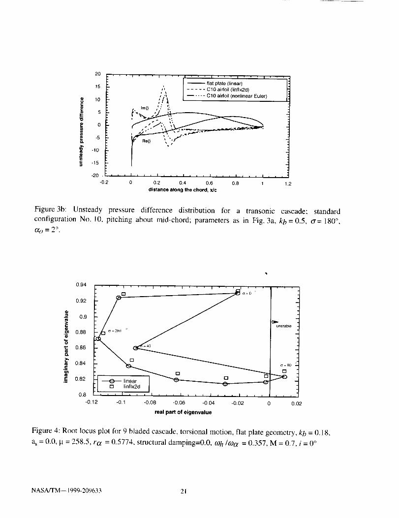
The unsteady pressure distribution from LINFLX2D is shown in Fig. 3b, along with a
comparison with linear theory (Ref. 3) and from the unsteady nonlinear Euler solver (Ref. 17).
The unsteady results are for pitching about mid-chord with kb- 0.5, o'= 180 ° and amplitude of
oscillation,O_o = 2 °. As expected, linear theory does not show any shock, indicating that
unsteady analysis based on linear theory will not be accurate for cascade flutter analysis in
transonic flow. Some discrepancy is seen between the unsteady results obtained from
LINFLX2D and from the unsteady nonlinear Euler solver. For the transonic flow case the
following factors may effect the results more than for subsonic case: (1) grids used, (2) accuracy
lost when time series data is processed to obtain frequency data or (3) the steady solution on
which LINFLX2D based is not a low loss solution. Even though these issues need separate
study, Fig. 3b shows a fair correlation between LIFLX2D results and non-linear unsteady Euler.
Similar results were obtained for plunging motion for both subsonic and transonic inflows.
NASA/TM--1999-209633 9

Unsteady Aerodynamic Force coefficients
It is the unsteady aerodynamic force coefficients, unsteady lift and moment that are obtained by
integrating unsteady pressure differences, which are used in the flutter and forced response
prediction. Table 1 shows the unsteady aerodynamic force coefficients obtained using the Smithcode, Ref. 3, the present LINFLX2D code, and the non-linear Euler solver of Ref. 17. In table 1,
the first column shows the geometry of the airfoil studied, the fourth, fifth and sixth columns
show the force components for pitching motion, plunging motion and for vortical gust
respectively. The symbols in the second column are cl for lift coefficient, and cm for moment
coefficient, with moment taken about the mid chord (x,. = 0.5). The rows show the geometry and
the Mach number studied. The analysis method is given in column 3 with the notation defined at
the bottom of the table. The geometry and unsteady conditions are given on the top of the table.
A comparison of the force coefficients for flat plate geometry in the first row shows that the
prediction by LINFLX2D are very close to those given by Smith code. For a flat plate geometryin subsonic flow, the Smith code gives the exact answer. It is to be noted that the flat plate is
unloaded and shock free. The values of the force coefficients in the second row show some
difference from the Smith code, since in LINFLX2D the effect of airfoil and angle of attack are
included. The force coefficients in the third row include the effect of shock and its motion in
addition to the effects of airfoil shape and angle of attack. The force coefficients obtained with
LINFLX2D code compare well with those obtained from a non-linear unsteady Euler solution,
indicating that LINFLX2D code can be used to analyze cascades in transonic flow. It is to be
noted that only limited runs for vortical gust response predictions have been made. It is also tobe noted that the solution for transonic flow could not be obtained with 155x41 grid considered
here for which the inlet and exit boundaries are at one chord length. It was suggested that for the
LINFLX2D code to work properly, it is better if the inlet and exit boundaries are at least
5 chords from the leading and trailing edges respectively (Ref. 20).
Flutter Calculations
As mentioned before, given the unsteady aerodynamic force coefficients, the MISER code
(Ref. 7) calculates the aeroelastic stability of tuned and mistuned cascades oscillating in pitch
and plunge. The aeroelastic stability results from MISER are presented as a root locus plot, with
real part of the eigenvalue indicating damping and the imaginary value indicating frequency for
all possible interblade phase angles. In the present study the unsteady aerodynamic forcecoefficients obtained from LINFLX2D are coupled with MISER as follows. First a steady
solution is obtained from NPHASE for the required cascade geometry and flow conditions. With
the steady solution as input, LINFLX2D is run for given a reduced frequency, interblade phase
angle, and mode of interest (pitching or plunging). The unsteady aerodynamic coefficientsobtained from LINFLX2D are then stored in a data base, and later used in MISER to calculate
the stability characteristics.
The structural properties are the mass ratio, It, is 258.50; ratio of bending to torsion
frequencies,toh/09ct is 0.357; the radius of gyration about the elastic axis in semi-chord units, rot,
is 0.5774; with no structural damping. The elastic axis (see Fig. 1) is at midchord, i.e. ah = 0.0.The distance between the elastic axis and center gravity, x_ is zero, indicating that coupling
between bending and torsion is very weak and the flutter mode is dominated by torsional motion.
NASA/TM-- 1999-209633 10

Therefore, only torsion mode is shown for all the calculations. It should be noted that thesestructural properties were also used in Refs. 7 and 8.
The following procedure is used for stability prediction. First MISER is run for the selected
cascade (rotor) using linear theory ( Ref. 3) to identify the flutter point. Then MISER is run
using the LINFLX2D data base for this flutter condition. The eigenvalues obtained from lineartheory and LINFLX2D are then compared.
Flat Plate Cascade
To validate the coupling of the unsteady aerodynamic coefficients obtained from LINFLX2D
with MISER, a nine bladed cascade with a flat plate geometry was selected. The flutter results
obtained are compared with those obtained from linear theory. The gap-to-chord ratio is unity
and the stagger angle is 45 degrees. For the nine bladed cascade, for a given reduced frequency,
the unsteady force coefficients have to be calculated for the possible interblade phase angles of 0,40, 80, 120, 160, 200, 240, 280, and 320 degrees.
Using linear theory, for M = 0.7 with elastic axis at midchord, for the nine bladed cascade
mentioned above, an instability was found at k h = 0.18 and at a phase angle of 80 degrees.
Therefore, LINFLX2D was run for this value of reduced frequency, and for all allowable phase
angles, and for both plunging and pitching oscillations, and a database was prepared. ThenMISER was run to predict the stability boundary with the unsteady aerodynamic force coefficientdata base obtained from LINFLX2D.
The root locus plot showing the real and imaginary parts of the eigenvalues for the flat plate
geometry obtained for torsion motion is given in Fig. 4. The unsteady force coefficients for eight
phase angles were obtained with LINFLX2D. For the c_ = 40 degrees, for which acoustic
resonance was expected, the LINFLX2D code did not give a solution for the grid, oscillation ofamplitude, and time step considered. This case will be studied further in future. It was noted
that for a flat plate geometry, the computational times were higher thafi those for airfoil geometry
(presented below). Figure 4 shows the comparison between predictions from linear theory andfrom LINFLX2D. It can be seen from Fig. 4 that LINFLX2D compares very well with lineartheory results for the flat plate geometry. The plot shows that the cascade is unstable at the 80"phase angle mode.
Mistuned Cascade
Results are presented now for cascades with mistuning. The type of mistuning considered is the
one in which the odd and even numbered blades have different torsional frequenciesl also known
as alternate blade mistuning. This has been studied in Refs. 7 and 8 with 1% and 1.5% alternate
mistuning. For 1% mistuning, the frequency ratio 0_t_/_ is 1.005 for all the even blades, and is
0.995 for all the odd blades. The study in Ref. 7 and 8 considered a 56 bladed cascade, and
showed that alternate mistuning has a considerable effect on stability. A 12 bladed cascade is
considered for the present study, to limit the computational time. MISER was run first for a
tuned cascade with linear theory, for M=0.7. It was found that the cascade is unstable for k h =
0.1 and o = 60". This value of k h = 0.1 is used for all the calculation presented below. It should
be noted here that for this cascade acoustic resonance was expected for o = 0" and 30". However,for the CI0 airfoil geometry unsteady solutions were obtained with LINFLX2D for these
NASA/TM-- 1999-209633 11

interblade phase angles also, unlike for the flat plate geometry for which solutions could not be
obtained with LINFLX2D at acoustic resonance (as mentioned in the previous section).
First, the amount of mistuning required to change the root locus plot is investigated, i.e., whether
the effects of 1% and 1.5% alternate as reported in Ref. 7 also occurs for this cascade. It should
be noted here that the results from the present MISER code were checked with those given in
Ref.7 for the 56 bladed cascade before starting the current calculations, and are given in
Appendix A for both flutter and forced response calculations. Figure 5 shows the root locus plotwith 1%,1.5%,5%,10% and 20% alternate mistuning for the flat plate geometry for M = 0.7 and
k b = 0.18. It can be seen that an alternate mistuning of 1-10% did not show any effect on the
eigenvalues. Only 20% alternate mistuning showed some effect on the eigenvalues. This is incontrast to the level of mistuning used in Ref. 7. However, Ref. 7 has considered a 56 bladed
cascade in incompressible flow for which the cascading effect is much stronger.
However, the large amount of mistuning required here to have a significant effect on the
eigenvalues (shown in Fig. 5) is not surprising. Similar values of mistuning have been used inRef. 8. That study used an amount of 1 to 20% mistuning. An examination of Fig. 11 of Ref. 8
showed that the effect of alternate mistuning decreased with increasing Mach number. In the
context of Ref. 8 and the present results, it is concluded that for the Mach numbers considered
here a mistuning of 20% or more has to be used to show a significant effect of on the
eigenvalues. Therefore, the rest of the calculations are done with 20% alternate mistuning.
Figure 6 shows the root locus plot obtained for the CI0 airfoil for both tuned and 20% alternatemistuning, for M = 0.7 and k_ = 0.1. Comparison with flat plate geometry is also shown. The
following are noted from Fig. 6: (1) For the tuned cascade both flat plate geometry cascade and
C10 airfoil cascade are unstable for _ = 60". However, the C10 cascade is less unstable than the
flat plate cascade. This indicates that for the tuned cascade the airfoil steady loading effects are
stabilizing, compared to that for a flat plate airfoil; (2) the addition of 20% alternate mistuningmoved the cascade with C10 geometry from an unstable to a stable condition, but the flat plate
cascade remained unstable; (3) the root locus plot for the C10 airfoil with mistuning has two
frequencies identified with a _y = 24ff _mode, whereas, the o - 60 ° mode is completely missing.
The reason for this behavior is under investigation.
The root locus plot for M = 0.8 and k h = 0.1 is shown in Fig. 7. The following are noted form
Fig. 7: (1)the tuned flat plate geometry cascade was unstable for _ - 90" and the C10 airfoilcascade was stable. This indicates that the airfoil steady loading effects are stabilizing for
the tuned cascade, compared to that for a flat plate airfoil; (2) the addition of alternate
mistuning made the C10 geometry more stable, but the flat plate cascade remained unstable;
(3) For the C10 airfoil it was noted that for tuned case both o = 90 " and o = 120 '' modes have the
same amount of damping, but with mistuning, o = 90 ° mode became more stable than the
o = 120 ° mode.
Forced Response Calculations
In the formulation for response prediction in MISER, it is possible to consider an excitation
function consisting of all harmonics of rotational speed of the rotor which range up to r = N- 1. In
engine aeroelastic terminology, the harmonic number r is known as the " engine order " of the
NASA/TM--1999-209633 12

excitation. The number of harmonics and interblade phase angles are related by Eq. 3 as
c_r=2nr/N r=O, 1,2.... ,N-1. The coefficients 1,,, and 1w,_,in Eq. 8 represent the forcing
functions in the bending and torsion equations, respectively. To understand the nature of the
response, excitation in only one harmonic at a time is considered. This results in no loss of
generality since the principle of superposition holds. If the r -- R harmonic is considered, then
the column matrices {AD_,}, {AD,} ..... {AD_,} are zero except {ADr}. Generally, a limited
number of engine order of excitations are of interest in forced response calculations. Thus, all
harmonics or all interblade phase angle modes need not be considered in forced response
analysis, as in flutter analysis. In the following only torsional response amplitudes are shown
since bending amplitudes are very small in the range of excitation frequency considered.
Figure 8 shows the tuned aeroelastic response for R = 6 i.e. cy = 180 degrees for flat plate
geometry. Again a twelve blade (N = 12) cascade with the same structural properties used for
flutter calculations is considered. However, a structural damping ratio of 0.002 is included in the
analysis. The unsteady aerodynamic coefficients are obtained at kb = 0.5 for which the cascade
is aeroelastically stable in all the modes. Calculations are done with a 155x41 grid for which the
inlet and exit boundaries are located at one chord from the leading and trailing edges
respectively. There are 55 points on the airfoil for this grid. The forcing frequency range
investigated is limited to a small range around the uncoupled torsional frequency. For the tuned
cascade, the response will be entirely in the r = R mode, and all the blades will have equal
amplitudes. The amplitude of response is a function of co / _. Figure 8 shows the torsional
response obtained using linear (Smith) theory and present LINFLX2D code for vortical gust
disturbance. The moments are taken about leading edge (ah = -1.0). Two responses are shown
in Fig. 8 one obtained by including the motion dependent aerodynamic matrix [A] in Eq. 12 and
the other without the contribution from [A]. The terms of [A] provide aerodynamic damping in
response calculations. It can be seen that calculations from Smith theory and from LINFLX2D
are identical indicating that the coupling of LINFLX2D coefficients to MISER code is accurate.
The inclusion of [A] in response calculations requires the calculation of motion dependent
unsteady aerodynamic coefficients for all interblade phase angles. However, as mentioned
earlier, in forced response calculations, only a limited number of interblade phase angles (engine
orders) are of interest and the calculations of motion dependent unsteady aerodynamic
coefficients is unnecessary. This essentially ignores the effect of aerodynamic damping on
response. As forced response is usually calculated for an aeroelastically stable system (positive
aerodynamic damping), this gives a conservative measure on the response calculations.
Therefore for further calculations the elements of matrix [A] are not included in the calculation.
Figure 9 shows the torsional response obtained for the standard configuration in subsonic flow
with and without 20% alternate mistuning. Comparing the response of C10 with that of flat
plate, it can be seen that the response has increased considerably. This may be due to high steady
loading on the airfoil. Also shown in Fig. 9 is the response with 20% alternate mistuning. The
response has split into two resonance peaks, one for odd blades and the other for even blades,
resonating at the 0.9 and 1.1 frequency ratios, as expected with no difference in amplitude. It
should be noted that the study of Ref. 7 showed that when the aerodynamic damping terms are
included in the response calculations, the amplitudes could be lower or higher depending on the
engine order.
NASA/TM-- 1999-209633 i 3

The calculationsgiven abovefor flat plate geometryshow that the LINFLX2D databaseisaccuratelycoupled with MISER for forced responsecalculations,as was shown for fluttercalculationsin theprevioussection.
CONCLUDING REMARKS
A two-dimensional unsteady linearized aerodynamic Euler solver, LINFLX2D was used to
calculate unsteady aerodynamic forces on oscillating cascades. The unsteady aerodynamic forceswere used in the aeroelastic code MISER to calculate flutter and forced response characteristics
of cascades. Results were presented for cascades in subsonic and transonic flow. Calculations
with the linearized Euler solver showed good correlation with the published data. The study also
showed that the unsteady aerodynamic force data base (for flutter and forced response) from
LINFLX2D is successfully coupled with MISER to calculate flutter and forced response of tuned
and mistuned cascades. The following were observed during the study.
(1) The airfoil steady loading stabilized the cascade for the Mach numbers considered.
(2) A relatively high amount of alternate mistuning is required to have an effect on the stabilityof the cascade for the Mach numbers considered.
(3) The steady loading due to the airfoil shape and angle of attack increased the blade response
compared to that for a flat plate.
(4) An accurate steady solution called "low loss solution " is required for the unsteady solver
LINFLX2D to work. This requires a considerable amount of computational time. This may
be the biggest drawback of using this code in a design cycle.
(5) The success of getting an unsteady solution from LINFLX2D also depended on the
grids used.
(6) For predicting flutter boundary, calculations have to be done for a range of reduced
frequencies. It is suggested that LINFLX2D data base be prepared for three or four reduced
frequencies, and then use interpolation for flutter calculations. These reduced frequencyvalues can be selected by first running MISER with linear theory.
(7) The unsteady aerodynamic solution times varied from 20 minutes to 75 minutes on an SGI
workstation. This is directly related to the number of iterations required for convergence. A
solution for flat plate geometry took more time than for the C 10 airfoil geometry.
(8) The LINFLX2D code can be used with any aeroelastic code that uses a typical section
aeroelastic model as its basis. It can be used with the NASA Glenn Research Center codes
ASTROP2, and FREPS with little modification.
NASA/TM-- 1999-209633 14

REFERENCES
(1) Reddy, et al, "A review of Recent Aeroelastic Analysis Methods for Propulsion at NASALewis Research Center", NASA TP 3406, December 1993.
(2) Whitehead, D.S., "Classical Two-Dimensional Methods", Chapter II in AGARD Manual on
Aeroelasticity in Axial Flow in Turbomachines, Vol. 1, Unsteady Turbomachinery
Aerodynamics, (ed. M. F. Platzer and F. O. Carta), AGARD-AG-298, pp. 3-1:3-30,March 1987.
(3) Smith, S.N., "Discrete Frequency Sound Generation in Axial Flow Turbomachines," British
Aeronautical Research Council, London, ARC R&M No. 3709, 1971.
(4) Adamczyk, J.J. and Goldstein, M.E., "Unsteady Flow in a Supersonic Cascade with
Subsonic Leading-Edge Locus", AIAA Journal, Vol. 16, No.12, pp. 1248-1254,December 1978.
(5) Surampudi, S.P. and Adamczyk, J.J., "Unsteady Transonic Flow over Cascade Blades",
AIAA Journal, Vol. 24, No. 2, Feb. 1986, pp. 293-302.
(6) Lane, F., "Supersonic Flow past an Oscillating Cascade with Supersonic Leading-Edge
Locus", Journal of the Aeronautical Sciences, Vol. 24, pp. 65-66, January 1957.
(7) Kaza, K.R.V. and Kielb, R.E., "Flutter and Response of a Mistuned Cascade in
Incompressible Flow," AIAA Journal, Vol. 20, No. 8, pp. 1120-1127, 1982.
(8) Kielb, R.E. and Kaza, K.R.V., "Aeroelastic Characteristics of a Cascade of Mistuned Blades
in Subsonic and Supersonic Flows", ASME Journal of Vibration, Acoustics, Stress and
Reliability of Design, Vol. 105, pp. 425-433, October 1983.
(9) Verdon, J.M., "Linearized Unsteady Aerodynamic Theory," Chapter II in AGARD Manual
on Aeroelasticity in Axial Flow in Turbomachines, Vol. 1, Unsteady TurbomachineryAerodynamics, (ed. M. F. Platzer and F. O. Carta), AGARD-AG-298, pp. 2-1:2-31,March 1987.
(10) Verdon, J.M. and Caspar, J.R., "Development of a Linear Unsteady Aerodynamic Analysis
for Finite Deflection Subsonic Cascades", AIAA Journal, Vol. 20, pp. 1259-1267, 1982.
(l l) Hoyniak, D., Verdon, J.V., "Steady and Linearized Unsteady Transonic Analyses of
Turbomachinery Blade Rows", 7th International Symposium on Unsteady Aerodynamics
and Aeroelasticity of Turbomachines, Fukuoka, Japan, Sept. 25-29, 1994, Y. Tanida and
M. Namba (editors), pp. 109-124, 1995, Published by Elsevier Science B.V.
(12) Smith, T.E. and Kadambi, J.R., "The Effect of Steady Aerodynamic loading on the
Flutter Stability of Turbomachinery Blading", Journal of Turbomachinery, Vol. 115, No. 1,pp. 167-174, 1993.
NASA/TM-- 1999-209633 15

(13) Hall, K.C. and Clark, W.S., "Linearized Euler Predictions of Unsteady Aerodynamic Loads
in Cascades", AIAA Journal, vol. 31, No. 3, pp. 540-550, March 1993.
(14) Holmes, D.G. and Chuang, H.A., "2D Linearized Harmonic Euler Flow Analysis for Flutter
and Forced Response", Unsteady Aerodynamic, Aeroacoustics, and Aeroelasticity of
Turbomachines and Propellers, pages 213-230, Ed. Atassi, H.M, Springer-Verlag,
New York, 1993.
(15) Kahl, G. and Klose, A., "Computation of Time Linearized Transonic Flow in Oscillating
Cascades", ASME Paper 93-GT-269, 38th IGT and Aeroengine Congress and Exposition,
Cincinnati, Ohio, May 24-27, 1993.
(16)Verdon, J.V., Montgomery, M.D. and Kousen, K.A., "Development of a Linearized
Unsteady Euler Analysis for Turbomachinery Blade Rows", NASA CR 4677, June 1995.
(17) Swafford, T.W., et al, "The Evolution of NPHASE: Euler/Navier-Stokes Computations of
Unsteady Two Dimensional Cascade Flow Fields", AIAA Paper 94-1834, 12th Applied
Aerodynamics Conference, Colorado Springs, Colorado, June 20-23, 1994.
(18) Lane, F., "System Mode Shapes in the Flutter of Compressor Blade Rows," Journal of the
Aeronautical Sciences, Vol. 23, pp. 54-66, January 1956.
(19) Verdon, J.M., "The Unsteady Aerodynamic Response to Arbitrary Modes of Blade Motion",
Journal of Fluids and Structures, Vol. 3, pp. 255-274, 1989.
(20) Capece, V., personal communication, University of California, Davis, 1997.
NASA/TM--1999-209633 16

APPENDIX A
Calculated results from the current Version of MISER
Over the years, many versions of MISER code have been in circulation. The present authors also
made some modifications to MISER. An important one was updating calls for numerical
routines from IMSL 9 to IMSL 10 and LAPACK numerical packages. So, calculations are
shown in this appendix to confirm that the authors' MISER code gives the same results as theMISER code used in Ref. 7 in 1982.
Flutter and forced response results are reproduced here by running the current version of the
MISER code for the example cases given in Ref. 7. A 56 blade rotor representative of a
compressor stage is used. The stagger angle is 54.4 degrees and the gap to chord ratio (s/c) is
0.534. The structural properties are the mass ratio, lU, is 258.50, ratio of bending to torsion
frequencies mh/coa is 0.357, the radius of gyration about the elastic axis in semi-chord units ro_
is 0.5774, with no structural damping. The elastic axis is at midchord i.e. ah = 0.0. The distance
between the elastic axis and center gravity, x_ is zero. Thus coupling between bending and
torsion is very weak, and the flutter mode is dominated by torsional motion. Therefore, only the
torsion mode is shown for all the calculations. The flow is considered incompressible.
Figure A. 1 shows the root locus plot obtained with and without mistuning for kb = 0.6425, and
for zero structural damping. These results are identical with Fig. 4 in Ref .7.
In figures A2 and A3, aeroelastic response for two engine orders, R = 11 and 39, are presented.
These engine orders correspond to interblade phase angles of 70.7 and 250.7 degrees
respectively. An alternate mistuning of 1%, and a structural damping of 0.002 is used in the
calculations, with kb = 1.2. These figures are identical with those shown as Fig. 1 l a and 1 l b
of Ref. 7.
NASA/TM-- !999-209633 17
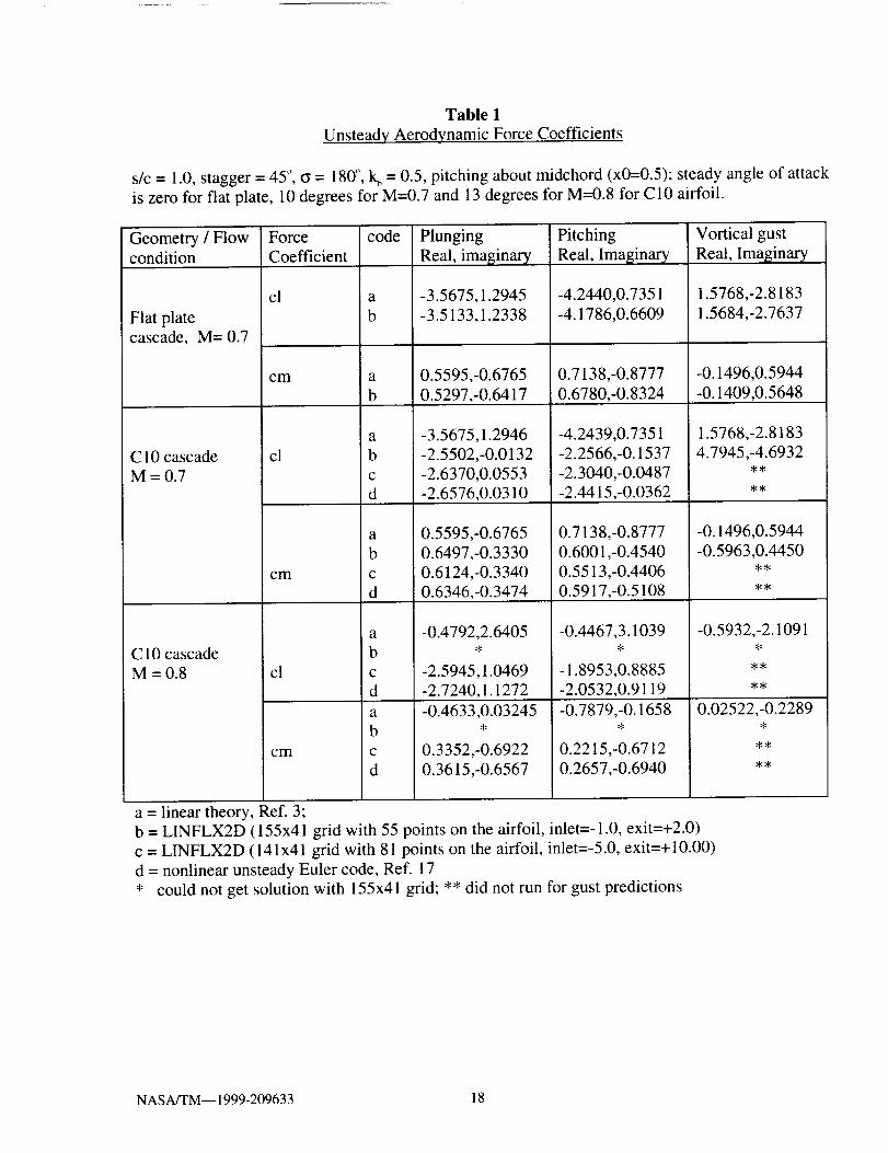
Table 1
Unsteady Aerodynamic Force Coefficients
s/c = 1.0, stagger = 45", _ = 180 °, k b = 0.5, pitching about midchord (x0=0.5); steady angle of attack
is zero for flat plate, 10 degrees for M=0.7 and 13 degrees for M=0.8 for C10 airfoil.
Geometry / Flow Forcecondition Coefficient
Flat platecascade, M= 0.7
C 10 cascade
M-0.7
C 10 cascade
M=0.8
code Plunging Pitching
Real, imaginary Real, Imaginary
cl a -3.5675,1.2945 -4.2440,0.7351
b -3.5133,1.2338 -4.1786,0.6609
cm
cl
cm
cl
cm
a 0.5595,-0.6765 0.7138,-0.8777
b 0.5297,-0.6417 0.6780,-0.8324
a -3.5675,1.2946 -4.2439,0.735 l
b -2.5502,-0.0132 -2.2566,-0.1537
c -2.6370,0.0553 -2.3040,-0.0487
d -2.6576,0.0310 -2.4415,-0.0362
a 0.5595,-0.6765 0.7138,-0.8777
b 0.6497,-0.3330 0.6001,-0.4540
c 0.6124,-0.3340 0.5513,-0.4406
d 0.6346,-0.3474 0.5917,-0.5108
a -0.4792,2.6405 -0.4467,3.1039
b 4 4
c -2.5945,1.0469 -1.8953,0.8885
d -2.7240,1.1272 -2.0532,0.9119
a -0.4633,0.03245 -0.7879,-0.1658b * *
c 0.3352,-0.6922 0.2215,-0.6712
d 0.3615,-0.6567 0.2657,-0.6940
Vortical gust
Real, Imaginary
1.5768,-2.8183
1.5684,-2.7637
-0.1496,0.5944
-0.1409,0.5648
1.5768,-2.8183
4.7945,-4.693244
4:_
-0.1496,0.5944
-0.5963,0.445044
-0.5932,-2.10914
44
_4
0.02522,-0.2289
44
a = linear theory, Ref. 3;b = LINFLX2D (155x41 grid with 55 points on the airfoil, inlet=-1.0, exit=+2.0)
c = LINFLX2D (141x41 grid with 81 points on the airfoil, inlet=-5.0, exit=+10.00)
d = nonlinear unsteady Euler code, Ref. 17
* could not get solution with 155x41 grid; ** did not run for gust predictions
NASA/TM-- 1999-209633 18

_b_l I
ihai o,,pos,,,oncenter .__
ofma_--" Iba,,I I?'..-zS_
axis
Figure I: Typical section blade model with two degrees-of-freedom.
oe-
t_
e_>,,
"O{u
¢ne-
20
15
10
5
0
-5
-10
-15
-20-0.2
, i ,
I: ' ' ' I ' ' ' I ' ' ' I ' ' ' I ' '
,, o',
I
%
"_ lmO
0 0.2 0.4 0.6 0.8 1
distance along the chord, x/c
Inflx2d
linear
i
1.2
Figure 2a: Unsteady pressure difference distribution for a flat plate geometry cascade; pitching
about mid-chord; gap-to-chord ratio, s/c = 1.0, stagger angle, 0 = 45 °, free stream Mach number,
M = 0.7, steady angle of attack, i = 0 °, reduced frequency based on semi-chord, kb = 0.5,
interblade phase angle, ff = 180 °, amplitude of oscillation, ao = 2 °.
NASA/TM-- 1999-209633 19

@Oe-
"O
'O
e-
- - - flat plate (linear)
15 _ ..... C10 airfoil (linflx2d)
ql,/ • C10 airfoil (nonlinear Euler)
1 005 ""_" "" 1
-10 ,_, , ii }-15
-20 , h , , , i , , , I , , , I , , , n , , ,
-0.2 0 0.2 0.4 0.6 0.8 t 1.2
distance along the chord, x/c
Figure 2b: Unsteady pressure difference distribution for a subsonic cascade, pitching aboutmidchord; , s/c = 1.0, 0 = 45 °, M = 0.7, kb = 0.5, G = 180 °, O_o= 2°, i = 0° for fiat plate and
i = 10° for C10 airfoil.
1.5
1.2
0.9
0.6
0.3
I I I I
upper surface I _ Euler I
% .m ° o...-
lower surface
0.0 n n i i
0.0 0.2 0.4 0.6 0.8 1.0
x/c
Figure 3a: Steady Mach number distribution for a transonic cascade; standard configuration
No. lO, s/c= 1.0, 0=45°,M=0.8, i = 13 ° .
NASA/TM-- 1999-209633 20
o
e,-
8.=_
8
"o
c
2O
15
10
5
0
-5
-10
-15
-20 . '
-0.2
.
i
0
I ' • ' ! • , • I " ' ' I " ' • I ' " " I ' ' '
_ flat plate (linear)," ..... C10 airfoil (linflx2d)t
,., ..... C10 airfoil (nonlinear Euler)
'.c. Iml} i., a,
Rel} \ "" f_"
0.2 0.4 0.6 0.8 1
distance along the chord, x/c
1.2
Figure3b: Unsteady pressure difference distribution for a transonic cascade; standard
configuration No. 10, pitching about mid-chord; parameters as in Fig. 3a, kb = 0.5, o'-- 180 °,
0(o=2 °.
0.94' ' ' I ' ' ' I ' ' ' ! ' ' ' I " ' ' I ' ' '
[] =jo:oL, 1
0.9_ nst_le
"6
0.86 =40 "
.E 0.82 _ linear
[] linflx2dI. I0.8 I , , , I , , , I 1 , , , I , , , II , , ,
-0.1: -0.1 -0.08 -0.06 -0.04 -0.02 0 0.02
real part of eigenvalue
Figure 4: Root locus plot for 9 bladed cascade, torsional motion, flat plate geometry, kb = 0.18,
a, = 0.0, !Lt= 258.5, ro_ = 0.5774, structural damping=O.O, Wh/(Oo_ = 0.357, M = 0.7, i = 0 °
NASA/TM-- 1999-209633 2 i

0.85
0.8
0
mm> 0.75t-OO}
"6 0.7
E' 0.65
C
.E_ 0.6
0,55
-0.2
.... I .... I .... ! ....
'. 10%
, , , , I i , i i I , , , , I , i a •
-0.16 -0.1 -0.05
.... I ....
")" unstable
0 0.05 0.1
real part of eigenvalue
Figure 5: Effect of alternate mistuning on eigenvalues in subsonic flow; flat plate geometry,M = 0.7, i = 0 °, kb = 0.1, N= 12, pitching about mid-chord;. 1%,2%,5%, 10%, 20%; structural
parameters same as in Fig. 4.
0.9
0.85
0_= 0.8a
c
I_ 0.75
'_ 0.7
ima.
0.65
.=
.__ o.6
' ' ' ' I " ' " I I ' " ' "
\\ "-,o. " .....-o- __j_ __&_ _,_
__°'=240° '_IPO -0411
I , , = | I ! , , , , . I I I , ,0.55 .... I , , ,
-0.2 -0.15 -0.1 -0.05 0 0.05
real part of eigenvalue
plate, tunedplate,mistuned
- -e- - C10, tuned- -.- - ClO,mistuned
unstsble
0.1
Figure 6: Effect of alternate mistuning on eigenvalues in subsonic flow; standard configuration
No. 10, M = 0.7, i = 10 °, kb = 0.1, N = 12, pitching about mid-chord; structural parameters same
as in Fig. 4.
NASA/TM-- 1999-209633 22

0.9
0.85
0.8
"_ 0.75
-$-_ o.7
_- 0.65
._ 0.6
._Eo.55
0.5
]
• .............. J ---e--- plate, tunea I
_J
_'_ 0=9
plate,mistuned--®-- C10, tuned- -o - - ClO,mistuned
un£e
-0.25 -0.2 -0.15 -0.1 -0.05 0 0.05 0.1
real part of eigenvalue
Figure 7: Effect of alternate mistuning on eigenvalues in transonic flow; standard configuration
No. 10, M = 0.8, i = 13 °, kb = 0.1, N = 12, pitching about mid-chord; structural parameters same
as in Fig. 4.
16
14
12
.__10
,_ 8"0
= 6o
9 4
o
0 ' ' "
0.85 0.9 0.95 1
" iOfli_rdo;ampilng' ' '] ' _
' ' ' ' I ' ' I ' I ' I ' ' ' '
/ ..... Withaero damping li_ "_1 o linflx2d
t "o
"Q.",Q
1.05 1.1 1.15 1.2
nondimensional forcing frequency
0.9
0.8
0.7
0.6
0.5
0.4
0.3
0.2
0.1
0
Q.
25"
Figure 8: Comparison of torsional response for a tuned cascade; flat plate geometry, M = 0.7,O
i - 0 , kb = 0.5, N = 12, pitching about leading edge; structural damping ratio = 0.002; structural
parameters same as in Fig. 4. Lines are calculations from linear theory.
NASAJTM-- 1999-209633 23

50 .... I .... I .... I .... I''''1''''1 .... I ....
40
,,. 30.£0
=o 20mM
.£ lO
9
-10
//clO+20%mistune !
evenblades i , / / 010 ,I / clO+20%mistune,odd blades"; //
;' I/ ''; , _,a,e / I; " /A' , ,
' ' / I, .,.
, , , , I , , , , I , , , , I , , , , I , , , , I , , , , I , , , , I , ' '
0.8 0.85 0.9 0.95 1 1.05 1.1 1.15
nondimensional forcing frequency
1.2
Figure 9: Effect of steady loading on torsional response, M = 0.7, i = 0 °, kb = 0.5, N = 12,
pitching about leading edge; structural damping ratio = 0.002; structural parameters same as in
Fig. 4.
1.00
0.995_=m==c
gl}
,,6 0.990
m
.=_ 0.985o_m._E
0.980
-- tuned .... - -- "-
-- -- - 1% mistuned f "_.
..... 1.5%mistuned ,,,_ _ _ -- _.. -- ,_
unstable
0.005-0.015 -0.01 -0.005 0
real part of elgenvalue
Figure A 1: Effect of alternate mistuning on eigenvalues in incompressible flow; flat plate,
incompressible flow, i = 0 °, kb = 0.642, N = 56, pitching about mid-chord; structural parameters
same as in Fig. 4 (identical with Fig.5 of Ref. 7).
NASA/TM-- 1999-209633 24

1• I • I , ' I • I •
0.6
_ 0.4
'_ 0.2 "_0
I% milltuning
0 , l , I i I i I i I ,
0.99 0.9925 0.995 0.9975 1 1.002 1.005nondimensional forcing frequency
Figure A.2: Effect of blade alternate mistuning on coupled bending-torsion response in
incompressible flow; flat plate, incompressible flow, i = 0 °, kb = 1.2, N = 56, R = 11, pitching
about mid-chord; structural damping ratio = 0.002; structural parameters same as in Fig. 4(identical with Fig. 1 la of Ref. 7).
1.5
O
"O
°_m
¢,jE
"_ 0.5c0
2
0
0.99
' I
f.--- \
I
' I ' I ' I ' I '
/
-, / \
1% mistuned _ _
i I iI i I , I , I ,
0.9925 0.995 0.9975 1 1.002 1.005
nondimensional forcing frequency
Figure A.3: Effect of blade alternate mistuning on coupled bending-torsion response in
incompressible flow; flat plate, incompressible flow, i = 0 °, kb = 1.2, N = 56, R = 39, pitching
about mid-chord; structural damping ratio = 0.002; structural parameters same as in Fig. 4(identical with Fig. 1 lb of Ref. 7)
NASA/TM-- 1999-209633 25

Form Approved
REPORT DOCUMENTATION PAGE OMB NO. 0704-0188
='ubliC reporling burden for this collection of information is estimated to average 1 hour per response, including the time for reviewing instructions, searching existing data sources,lathering and maintaining the data needed, and completing and reviewing the collection of information. Send comments regarding this burden estimate or any other aspect of thisotlection of information, including suggestions for reducing this burden, to Washington Headquarters Services. Directorate for Information Operations and Reports, 1215 Jefferson
Davis Highway, Suite 1204, Arlington VA 22202-4302, and to the Office of Management and Budget. Paperwork Reduction Project (0704-0188}, Washington, DC 20503.
1. AGENCY USE ONLY (Leave blank) 2. REPORT DATE 3. REPORT TYPE AND DATES COVEREDNovember 1999
4. TITLE AND SUBTITLE
Flutter and Forced Response Analyses of Cascades Using a Two-Dimensional
Linearized Euler Solver
6. AUTHOR(S)
T.S.R. Reddy, R. Srivastava, and O. Mehmed
7. PERFORMING ORGANIZATION NAME(S) AND ADDRESS(ES)
National Aeronautics and Space Administration
John H. Glenn Research Center at Lewis Field
Cleveland, Ohio 44135- 3191
9. SPONSORING/MONITORING AGENCY NAME(S) AND ADDRESS(ES)
National Aeronautics and Space Administration
Washington. DC 20546-0001
Technical Memorandum
5. FUNDING NUMBERS
WU-523-26-13-00
8. PERFORMING ORGANIZATIONREPORT NUMBER
E-11960
10. SPONSORING/MONITORINGAGENCY REPORT NUMBER
NASA TM--1999-209633
11. SUPPLEMENTARY NOTES
T.S.R. Reddy and R. Srivastava, The University of Toledo, Toledo, Ohio 43606; O. Mehmed, NASA Glenn Research
Center. Responsible person, O. Mehmed, organization code 5930, (216) 433-6036.
12a. DISTRIBUTION/AVAILABILITY STATEMENT12b. DISTRIBUTION CODE
Unclassified - Unlimited
Subject Category: 39Distribution: Nonstandard
This publication is available from the NASA Center for AeroSpace Information, (301) 621-0390
13. ABSTRACT (Maximum 200 words)
Flutter and forced response analyses for a cascade of blades in subsonic and transonic flow is presented. The structural
model for each blade is a typical section with bending and torsion degrees of freedom. The unsteady aerodynamic forces
due to bending and torsion motions, and due to a vortical gust disturbance are obtained by solving unsteady linearized
Euler equations. The unsteady linearized equations are obtained by iinearizing the unsteady nonlinear equations about the
steady flow. The predicted unsteady aerodynamic forces include the effect of steady aerodynamic loading due to airfoil
shape, thickness and angle of attack. The aeroelastic equations are solved in the frequency domain by coupling the un-
steady aerodynamic forces to the aesroelastic solver MISER. The present unsteady aerodynamic solver showed good
correlation with published results for both flutter and forced response predictions. Further improvements are required to
use the unsteady aerodynamic solver in a design cycle.
14. SUBJECT TERMS
Flutter; Forced response; Cascades; Euler; Linearized; Mistuned
17. SECURITY CLASSIFICATION 18. SECURITY CLASSIFICATION 19. SECURITYCLASSIFICATIONOF REPORT OF THIS PAGE OF ABSTRACT
Unclassified Unclassified Unclassified
15. NUMBER OF PAGES
3116. PRICE CODE
A0320. LIMITATION OF ABSTRACT
Standard Form 298 (Rev. 2-89)NSN 7540-01-280-5500 Prescribed by ANSI Std. Z39-18
298-102

