fluor / uop gtc 2004 synthesis gas purification in ... · pdf filefluor / uop gtc 2004...
TRANSCRIPT

FLUOR / UOP GTC 2004 Synthesis Gas Purification in Gasification to Ammonia/Urea Complex ABSTRACT This paper compares two commercially proven syngas purification processes for a gasification-based ammonia/urea fertilizer complex. Capital and operating costs of a new Selexol/PSA process and the conventional Rectisol/Nitrogen Wash process are compared, in two fertilizer plant configurations: Coal-to-Ammonia plant and Coal-to-Ammonia/Urea plant. The operation and performance of the Selexol/PSA synthesis gas purification sequence has now been demonstrated in the Coffeyville Resources Gasification Ammonia Complex. INTRODUCTION With today’s increasing natural gas prices, the gasification route of low value feedstocks to produce ammonia/urea fertilizer is becoming the economical choice. However, the gas purification steps of the gasified products require significant energy and are costly. An optimum purification process is one of the important factors in the success of a fertilizer complex. The selected process must be commercially proven and have high conversion efficiency and high reliability. The following case studies [1], [3], [5]
compare the new Selexol/PSA process to the conventional Rectisol/Nitrogen Wash process for gas purification in a Coal-to-Ammonia/Urea fertilizer complex. The differences in process configurations, hydrogen recovery efficiencies, energy consumption, and impacts on the fertilizer complex, as well as capital and operating costs are evaluated. The option of CO2 co-production for urea manufacture is also evaluated. Material balances and flow diagrams are developed for each option based on 2,000 MTD of ammonia production and co-production of 1,475 MTD of CO2 for urea manufacture. The Selexol/PSA syngas purification sequence has been successfully demonstrated in the Coffeyville Resources Gasification Ammonia Complex for ammonia and urea production. This fertilizer complex uses refinery petroleum coke in the production of syngas using the ChevronTexaco (now owned by GE) gasification process. CASE STUDIES The fertilizer complex configuration, process design and material balance for the two syngas purification processes for ammonia and CO2 co-production are described in the following section. Illinois No.6 coal is used as the feed basis for this study. Case 1: Selexol/PSA Design Case 1 uses the new Selexol/PSA for acid gas removal and hydrogen purification. This is the base case of comparison. The fertilizer complex is based on 2,000 MTD ammonia production rate. The required coal feed rate to the gasifiers is 2,593 MTD. The gasification complex block diagram is shown in Figure 1, and the material balance is summarized in Table 1.

FLUOR / UOP GTC 2004 Synthesis Gas Purification in Gasification to Ammonia/Urea Complex
Figure 1- Gasification to Ammonia Complex with Selexol/ PSA Design
A single train of Air Separation Unit (ASU) is used to supply 2,340 MTD of 99.5% purity high pressure oxygen to the gasification unit, and low pressure oxygen to the Claus Unit. Only a small portion of the oxygen product from the ASU is required for the Claus unit. With the use of oxygen in the Claus reaction, the sulfur plant size is significantly reduced, and the sulfur conversion efficiency is improved. In addition, the ASU also supplies high pressure nitrogen to the ammonia plant. The nitrogen is mixed with hydrogen from the Hydrogen Recovery Unit (PSA) to obtain an optimum stoichiometric ratio of nitrogen to hydrogen to the ammonia plant. This configuration minimizes purging from the ammonia synthesis loop, improving the overall ammonia conversion efficiency. The ASU also produces low pressure nitrogen for purging in the PSA unit that reduces hydrogen losses in the PSA purge stream. Coal from storage is conveyed at a rate of 2,593 MTD to the coal grinding and slurry preparation system. Coal and recycle carbon is wet-ground with water to produce a coal-slurry. The slurry and a 99.5% purity oxygen stream from the ASU are fed to the ChevronTexaco Quench Gasifier operating at 1,000 psig for the generation of a raw syngas stream. The particulate-laden quench and scrubber water stream is later treated for soot removal and recovery of unconverted carbon.

FLUOR / UOP GTC 2004 Synthesis Gas Purification in Gasification to Ammonia/Urea Complex
Table 1 – Case 1 Material Balance for Selexol/PSA
CO in the syngas from the gasification unit is converted to hydrogen using two-stage sour shift reactors via the water-shift reaction. CO + H2O H2 + CO2
Since the scrubbed syngas from the gasification unit is already saturated with steam, addition of steam is not required for the CO shift reaction. The waste heat from the reactor effluent is used to generate various levels of steam. The CO shift catalyst also converts COS to CO2 and H2S by the catalytic hydrolysis reaction, which occurs in the presence of steam. COS + H2O H2S+ CO2 The shifted syngas is then fed to the Selexol unit, which is designed to remove minimum 99.5% of the H2S from the syngas and to produce a CO2 stream that can be optionally used for urea manufacture. The process flow diagram for the Selexol unit is depicted in Figure 2. Selexol Unit The raw syngas is cooled to ambient temperature with steam generation and ambient coolers prior to the Selexol unit. The syngas is scrubbed in the HP Absorber with a mildly refrigerated lean solvent at about 32°F. The HP Absorber reduces the H2S content of the syngas from 0.92 mol % to 18 ppmv, while simultaneously removing about 50% of the COS content. The HP Absorber operates at about 910 psig and is designed with an inter-cooler and a pump-around circuit. Semi-rich solvent is withdrawn from the mid section of the absorber and chilled with refrigeration, maintaining an absorber bottom temperature of 72°F. A lower solvent temperature would increase the solvent’s acid gas loading and reduce solvent circulation, but this must be justified by the
Stream Number
1 2 3 4 5 6 7 8 9 10 11 12 13
Description Coal Feed Coal Slurry To
Gasifiers
Oxygen To Gasifiers
Raw Syngas
Scrubbed Syngas
Shifted Syngas To
Selexol
Sulfur From Oxygen
Claus Unit
Treated Syngas To
PSA
Total Purge Gas
LP Nitrogen
From ASU
HP Nitrogen
From ASU
Hydrogen From PSA
Syngas To Ammonia Synthesis
Lb mol / hr (lb/hr) (lb/hr)
CO 9,722 9,722 445 444 445
Hydrogen 8,065 8,065 17,330 17,315 1,053 16,276 16,276
CO2 3,751 3,751 12,941 9,522 12,941
Methane 22 22 22 22 19 3 3
Argon 25 33 33 33 33 22 12 12
Nitrogen 9 97 97 97 97 4,168 4,240 5,216 169 5,385
H2S 286 286 293 1 1
COS 7 7 0 0 0
H2O 145,973 5,777 34,169 65 64 64
Oxygen 6,685
Sulfur 293
Coal 238,167 238,167
Total 238,167 384,140 6,718 27,761 56,153 31,226 293 27,498 18,714 4,240 5,216 16,460 21,676
Mol Wt 32 21 19 20 32 17 36 28 28 2 9

FLUOR / UOP GTC 2004 Synthesis Gas Purification in Gasification to Ammonia/Urea Complex higher refrigeration consumption. Also the lower mass transfer efficiency due to the higher solvent viscosity from lower operating temperature must be considered. The rich solvent from the HP Absorber is letdown in pressure to 430 psig. The flashed gas is compressed by the Flash Gas Compressor and recycled back to the absorber, to reduce hydrogen losses. The rich solvent is sequentially heated in two lean/rich exchangers to 245 ºF and is letdown in pressure to about 170 psig. The low pressure flashed vapor, containing mostly acid gases, is scrubbed with a lean solvent in the H
2S Concentrator where H2S is re-absorbed and CO2 is rejected to the overhead. The resultant rich
solvent is enriched in H2S. The H2S content in the acid gas to the sulfur plant is increased to over 40%, as observed in actual plant operation. The overhead vapor from the H2S Concentrator is mixed with the lean solvent, cooled in a feed/effluent exchanger and chilled in a refrigerant chiller. The chiller outlet is flashed to a separator, producing a flashed vapor with a low ppmv level of H2S, and a CO2 saturated solvent. The vapor is suitable to be further purified for CO2 production for urea manufacture. The CO2 saturated solvent is pumped back to the H2S Concentrator for H2S absorption. In this configuration, the tail gas from the sulfur plant is hydrogenated, compressed and fed to the H2S Concentrator for sulfur removal. With this design, emissions from conventional tail gas units are eliminated.
Figure 2 – Selexol Unit

FLUOR / UOP GTC 2004 Synthesis Gas Purification in Gasification to Ammonia/Urea Complex PSA Unit The PSA unit purifies the treated gas from the Selexol unit in the production of 98.8% purity hydrogen for the ammonia plant. The PSA unit uses multi-bed adsorption/desorption cycle design. The new improvement is the use of nitrogen for purging the beds during the desorption cycle, comparing to the use of hydrogen in conventional design. Since nitrogen is available as a by-product from the air separation plant, there is no added cost for using this resource. The use of nitrogen for purging the PSA beds improves its hydrogen recovery efficiency, typically from 88 - 90% to 92 - 94%. The tail gas from the PSA unit, containing CO2, nitrogen and small quantities of hydrogen and CO, can be sent to a waste heat recovery boiler for recovery of its heat content. Due to the low heating value of this purge gas, supplementary fuel gas is required. Case 2: Selexol / PSA with CO2 Production The basic configuration of Case 2 is similar to Case 1. In this option, a portion of the CO2 stream from the Selexol unit is purified to produce 1,475 MTD CO2 for urea manufacture. The gasification complex block diagram is shown in Figure 3, and the material balance is summarized in Table 2. The CO2 compression, purification and liquefaction train is shown in Figure 4. The CO2 stream from the H2S Concentrator in the Selexol unit is compressed from 170 psig to 410 psig and fed to the purification section. The CO2 stream contains a small quantity of COS which must be removed to meet the total sulfur specification of the urea plant. The removal steps include steam injection and heating to promote hydrolyzing the residual COS to H2S. The effluent is then treated in a sulfur scavenger bed such as Zinc Oxide beds for sulfur removal. The sulfur-free CO2 stream is cooled by cooling water, and the condensed water is removed in a knockout drum. The CO2 stream is dried using molecular sieve dehydrators that is necessary to avoid water freezing in the downstream cold section. The CO2 stream is sequentially cooled with feed/effluent exchangers and chilled by a refrigerant chiller to about 5°F. The chilled two-phase stream is separated in a separator, and the flashed liquid is routed to a stripper where the residual inert components, mainly hydrogen and CO are stripped. To meet the urea plant feed conditions, a vapor CO2 stream and a high pressure liquid CO2 stream are produced. A portion of the stripper bottoms is pumped to high pressure, and the remaining portion is re-vaporized using the heat content in the feed gas.

FLUOR / UOP GTC 2004 Synthesis Gas Purification in Gasification to Ammonia/Urea Complex
Figure 3 - Gasification to Ammonia Complex with Selexol/ PSA Design and CO2 Production

FLUOR / UOP GTC 2004 Synthesis Gas Purification in Gasification to Ammonia/Urea Complex
Table 2 – Case 2 Material Balance for Selexol/PSA with CO2 Production
Figure 4 - CO2 Compression, Purification and Liquefaction
Stream Number
1 2 3 4 5 6 7 8 9 10 11 12 13 14 15
Description Coal Feed
Coal Slurry To Gasifiers
Oxygen To
Gasifiers
Raw Syngas
Scrubbed Syngas
Shifted Syngas
To Selexol
Sulfur Treated Syngas To PSA
Total Purge Gas
LP Nitrogen
From ASU
HP Nitrogen
From ASU
Hydrogen From PSA
Syngas To
Ammonia Synthesis
LP (Gas) CO2 To
Urea Plant
HP (Liquid) CO2 To
Urea Plant
Lb mol /hr (lb/hr) (lb/hr)
CO 9,722 9,722 445 444 444
Hydrogen 8,065 8,065 17,330 17,315 1,039 16,276 16,276
CO2 3,751 3,751 12,941 9,522 9,861 1,232 1,848
Methane 22 22 22 22 19 3 3
Argon 25 33 33 33 33 22 12 12 0 0
Nitrogen 9 97 97 97 97 4,168 4,240 5,216 169 5,385 0 0
H2S 286 286 293 1 1
COS 7 7 0 0 0
H2O 145,973 5,777 34,169 65 64 64
Oxygen 6,685
Sulfur 293
Coal 238,167 238,167
TOTAL 238,167 384,140 6,718 27,761 56,153 31,226 293 27,498 15,634 4,240 5,216 16,460 21,676 1,232 1,848
Mol Wt 32 21 19 20 32 17 36 28 28 2 9 44 44
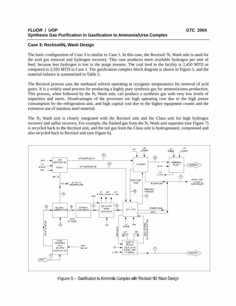
FLUOR / UOP GTC 2004 Synthesis Gas Purification in Gasification to Ammonia/Urea Complex Case 3: Rectisol/N2 Wash Design The basic configuration of Case 3 is similar to Case 1. In this case, the Rectisol/ N2 Wash unit is used for the acid gas removal and hydrogen recovery. This case produces more available hydrogen per unit of feed, because less hydrogen is lost in the purge streams. The coal feed to the facility is 2,450 MTD as compared to 2,593 MTD in Case 1. The gasification complex block diagram is shown in Figure 5, and the material balance is summarized in Table 3. The Rectisol process uses the methanol solvent operating at cryogenic temperatures for removal of acid gases. It is a widely used process for producing a highly pure synthesis gas for ammonia/urea production. This process, when followed by the N2 Wash unit, can produce a synthesis gas with very low levels of impurities and inerts. Disadvantages of the processes are high operating cost due to the high power consumption by the refrigeration unit, and high capital cost due to the higher equipment counts and the extensive use of stainless steel material. The N2 Wash unit is closely integrated with the Rectisol unit and the Claus unit for high hydrogen recovery and sulfur recovery. For example, the flashed gas from the N2 Wash unit separator (see Figure 7) is recycled back to the Rectisol unit, and the tail gas from the Claus unit is hydrogenated, compressed and also recycled back to Rectisol unit (see Figure 6).
Figure 5 – Gasification to Ammonia Complex with Rectisol/ N2 Wash Design

FLUOR / UOP GTC 2004 Synthesis Gas Purification in Gasification to Ammonia/Urea Complex
Table 3 – Case 3 Material Balance for Rectisol/ N2 Wash Design
Figure 6 – Typical Rectisol Wash Unit
Stream Number
1 2 3 4 5 6 7 8 9 10 11 12 13
Description Coal Feed To Slurry
Coal Slurry To Gasifiers
Oxygen To
Gasifiers
Raw Syngas
Scrubbed Syngas
Shifted Syngas
To Rectisol
Sulfur Treated Syngas To N2 Wash
Total Purge Gas
Stripping Nitrogen
From ASU
HP Nitrogen
From ASU
Recycle Gas
From N2 Wash
Syngas To
Ammonia Synthesis
Lbmol /hr (lb/hr) (lb/hr )
CO 7,574 7,574 347 339 0 3
Hydrogen 7,621 7,621 16,375 16,387 99 74 16,276
CO2 3,319 3,319 11,456 11,456
Methane 78 78 78 71 78
Argon 23 22 22 22 21 22 1 0 1
Nitrogen 9 157 157 157 174 1,541 1,082 5,688 5 5,385
H2S 247 247 254
COS 7 7 0
H2O 137,954 5,452 25,012 47 47
Oxygen 6,326
Sulfur 254
Coal 225,083 225,083
Total 225,083 363,038 6,358 24,477 44,037 28,735 254 16,993 13,589 1,082 5,688 82 21,662
MOL WT 32 19 19 20 32 3 42 28 28 5 9

FLUOR / UOP GTC 2004 Synthesis Gas Purification in Gasification to Ammonia/Urea Complex
Figure 7 – Typical N2 Wash Unit Rectisol Unit The process flow diagram of a typical Rectisol unit is depicted in Figure 6. The methanol scrubber consists of an upper bulk CO2 removal section and a lower H2S removal section. A portion of the CO2 rich methanol is drawn from the CO2 removal section and letdown in pressure to the CO2 flash drum. The H2S saturated methanol from the bottom of the H2S removal section is letdown to the H2S flash drum. The flash gas from both drums is recompressed and recycled to the inlet of the unit. The gas stream from the top of this column is warmed by the incoming syngas and is then sent to the CO2 /Methanol Adsorbers (Figure 7). The rich methanol from the CO2 Stripper is sent to the H2S Concentrator. Low pressure nitrogen from the air separation plant is used in the H2S concentrator for stripping CO2 from the rich solvent, thereby concentrating its H2S content. The use of nitrogen for stripping increases the H2S concentration of the acid gas to the Claus unit. N2 Wash Unit Per Figure 7, the N2 Wash Unit mainly consists of a cold box, a N2 wash column and a flash drum. The feed gas from the Methanol Scrubber column is treated in the CO2 /Methanol Adsorber. Traces of CO2 and methanol contaminants are removed in the Adsorber to avoid the formation of solids inside the cryogenic section of the unit. The treated gas from the Adsorber is cooled down against product streams and is then sent to the N2 Wash column. The residual impurities in the hydrogen syngas (i.e. Argon, CO and methane) are removed by means of liquid nitrogen. Cooling is accomplished by Joule-Thompson effect. Purified gas leaves the top of the N2 Wash column and is sent to ammonia synthesis loop. The liquid from the bottom of the column is expanded into a flash drum. The flash gas is recycled back to the

FLUOR / UOP GTC 2004 Synthesis Gas Purification in Gasification to Ammonia/Urea Complex Rectisol unit while the column bottoms is vaporized against incoming feed streams, providing cooling to the feed streams prior to being recovered as fuel gas. The nitrogen, required for the wash process and as feed to the ammonia plant, enters the cold box and is cooled against the product streams. The nitrogen is split into two streams. One stream is further cooled and sent to the top of the column for absorption. The other stream is added to the purified hydrogen to obtain the optimum stoichiometric feed ratio to the ammonia plant. Case 4: Rectisol/N2 Wash with CO2 Production This case is the same as Case 3, with the additional of a CO2 compression and purification unit for urea manufacture. A portion of the CO2 stream is sent to the CO2 compression and Purification unit (Figure 4) while the remainder is sent to the waste heat recovery boiler for recovery of its heat content. The gasification complex block diagram is shown in Figure 8, and the material balance is summarized in Table 4. Differences between the Selexol/PSA and the Rectisol/N2 Wash design The main differences between the Selexol/PSA and the Rectisol/N2 Wash design are summarized in the following • The Rectisol unit removes all the CO2 and H2S from the syngas, while the Selexol unit can be used to
selectively remove H2S. Remaining CO2 in the treated gas from the Selexol unit is removed in the PSA unit.
• The Rectisol absorber operates under cryogenic temperatures (typical -80°F) while the Selexol absorber operates at mildly refrigerated temperatures (0 to 70°F). The cryogenic temperature refrigeration requires significantly higher power consumption.
• The Selexol and PSA unit equipment require carbon steel material, while the Rectisol and N2 wash unit equipment require the use of stainless steel material and hence higher equipment costs.
• The Rectisol / N2 wash design produces a very pure syngas, free of contaminants and inerts. Consequently, there is almost no purge required in ammonia synthesis. On the other hand, the inert content (mainly argon and methane) from the PSA product gas amounts to 200 to 500 ppmv, and subsequently a small purge from the ammonia plant is necessary. In addition, an oxygen removal step may be needed in the PSA case if the oxygen content of the nitrogen from the air separation plant exceeds the ammonia converter limit.
• The Rectisol unit requires nitrogen to strip CO2 from the rich solvent for concentrating H2S in the acid gas to the sulfur plant. In the Selexol design, H2S can be concentrated by flashing the rich solvent and rejecting its CO2 content in the H2S Concentrator.
• The Rectisol process produces CO2 at a lower pressure (18 psig) than the Selexol process (170 psig). Consequently, the CO2 compression train requires additional compression stages for the Rectisol case.

FLUOR / UOP GTC 2004 Synthesis Gas Purification in Gasification to Ammonia/Urea Complex
Table 4 – Case 4 Material Balance for Rectisol/ N2 Wash with CO2 Production
Figure 8 - Gasification to Ammonia Complex with Rectisol/ N2 Wash Design and CO2 Production
Stream Number
1 2 3 4 5 6 7 8 9 10 11 12 13 14 15
Description Coal Feed
Coal Slurry To Gasifiers
Oxygen To
Gasifiers
Raw Syngas
Scrubbed Syngas
Shifted Syngas
To Rectisol
Sulfur Treated Syngas To N2 Wash
Total Purge Gas
Stripping Nitrogen
From ASU
HP Nitrogen
From ASU
Recycle Gas
From N2 Wash
Syngas To
Ammonia Synthesis
LP (Gas) CO2 To
Urea Plant
HP (Liquid) CO2 To
Urea Plant
Lb mol/hr (lb/hr) (lb/hr)
CO 7,574 7,574 347 339 0 3
Hydrogen 7,621 7,621 16,375 16,387 99 74 16,276
CO2 3,319 3,319 11,456 8,376 1,232 1,848
Methane 78 78 78 71 78
Argon 23 22 22 22 21 22 1 0 1
Nitrogen 9 157 157 157 174 1,541 1,082 5,688 5 5,385
H2S 247 247 254
COS 7 7 1
H2O 137,954 5,452 25,012 47 47
Oxygen 6,326 254
Sulfur
Coal 225,083 225,083
Total 225,083 363,038 6,358 24,477 44,037 28,735 254 16,993 10,509 1,082 5,688 82 21,662 1232 4848
Mol Wt 32 19 19 20 32 3 42 28 28 5 9 44 44

FLUOR / UOP GTC 2004 Synthesis Gas Purification in Gasification to Ammonia/Urea Complex
COST EVALUATION Capital Cost Capital cost estimates were analyzed for each of the four cases using equipment and unit capacity factoring techniques and licensor quotations. The capital costs are based on a US location and third quarter 2003 time frame. The capital cost estimation results are summarized in Table 5. Note that the capital costs were developed to allow comparison of the incremental costs among different processing options. The actual capital costs of the facilities are less accurate, as they depend on project specific factors such as site location, client standards and plant operator requirements. The capital costs for the units surrounding the Selexol/PSA Unit (or Rectisol/N2 Wash process), i.e. the balance of plant (BOP), are determined using the overall unit capacity-factoring method. The balance of plant represents the sum of the upstream units and does not include the cost of any units downstream of the purification unit. The costs of the downstream units are the same for all the cases for the same ammonia production. As seen in Table 5, the capital cost for the BOP for the Rectisol/N2 Wash unit is less than that for the Selexol/PSA process. This is due to the smaller upstream units because of the higher hydrogen recovery efficiency of the Rectisol/N2 Wash design. The overall incremental cost savings for selecting the Selexol/PSA process over the Rectisol/N2 Wash process are approximately $26 to $31 MM for without and with CO2 production respectively.
Case 1
(Selexol / PSA)
Case 3 (Rectisol / N2
Wash)
Case 2 (Selexol / PSA)
Case 4 (Rectisol / N2
Wash)
Capital Cost ($1,000) No CO2 Production With CO2 Production
Selexol Unit 22,862 N / A 22,862 N / A
PSA Unit 25,000 N / A 25,000 N / A
Rectisol /N2 Wash Units N / A 91,640 N / A 91,640
Balance of Plant (BOP) 430,080 412,020 434,014 416,990
Incremental Capital Costs Base 43,788 0 43,788
Incremental BOP Costs Base (18,060) 3,934 (13,090)
Incremental Overall Plant Capital Costs Base 25,718 3,934 30,688
Table 5 – Comparison of Capital Costs between Selexol / PSA and Rectisol / N2 Wash
Operating Costs

FLUOR / UOP GTC 2004 Synthesis Gas Purification in Gasification to Ammonia/Urea Complex The operating costs for the overall plant are divided into fixed and variable components. The fixed costs are composed of operating labor, maintenance labor, and administration, support labor and maintenance materials. The variable operating costs depend upon the capacity and operating efficiency of the plant and are composed of utility costs, feed costs and catalyst and chemical costs. The coal feed is based on $46/ short ton, fuel gas is valued at $5/MM Btu and electric power at $60 /MW. A summary of the operating costs can be found in Table 6. The plant operating cost savings resulted by choosing Selexol/PSA over Rectisol/N2 Wash are about $1.9 to $3.2 MM per year for without and with CO2 production respectively.
Case 1
(Selexol / PSA)
Case 3 (Rectisol / N2
Wash)
Case 2 (Selexol / PSA)
Case 4 (Rectisol / N2
Wash)
Operating Cost ($ x 1000) No CO2 Production With CO2 Production
Annual Fixed Operating Costs 19,430 19,900 19,512 20,174
Annual Utilities & Feed Costs 51,480 52,830 54,785 57,289
Annual Catalyst & Chemical Costs 1,500 1,530 1,840 1,830
Total Annual Operating Costs 72,410 74,260 76,137 79,292
Incremental Annual Fixed Op. Costs Base 470 82 744
Incremental Annual Utilities & Feed Costs Base 1,350 3,305 5,809
Incremental Annual Cat. & Chem. Costs Base 30 340 330
Incremental Total Operating Costs Base 1,850 3,727 6,882
Table 6 – Comparison of Operating Costs between Selexol / PSA and Rectisol / N2 Wash
EFFECT OF OPERATING PARAMETERS ON PLANT PERFORMANCE Other operating parameters, feedstock types and gasification technologies, were also compared for the two different purification routes. Heat and material balances were developed for the Selexol/PSA and the Rectisol/N2 Wash processes for two other feedstocks: coke and residual oil. Petroleum Coke Petroleum coke (usually from a delayed coker) can be used as a feedstock to the gasification unit for synthesis gas production. The gasification plant requires less coke than coal to produce the same amount of ammonia. This is due to the higher heating value of petroleum coke as compared to that of coal. Coal contains inert materials, such as sulfur and ash and is typically at least 15% lower in heating value than coke. As a result, the front-end of the plant is about 15% smaller in size. Similar to previous analysis, less petroleum coke (about 6%) is required for the Rectisol/N2 Wash case due to its higher hydrogen recovery than the Selexol/PSA case.

FLUOR / UOP GTC 2004 Synthesis Gas Purification in Gasification to Ammonia/Urea Complex Residual Oil Residual oils such as vacuum residue, tar, and asphalt can be used as a gasifier feedstock. The following table is based on tar as the residual oil. When other types of residual oil are used, the amount of feed and the utility consumption vary and in general, the feedstock requirement increases in the order of vacuum residue, tar and asphalt. The gasification unit requires about 38% less feed when residual oil is used instead of coal for the same ammonia plant production. An oil-fed gasification facility typically costs significantly less than a coal or coke fed gasification plant because the costly front-end solid handling equipment is not required. Similar to previous analysis, less residual oil (about 6%) is required for the Rectisol/N2 Wash case due to its higher hydrogen recovery than the Selexol/PSA case. Table 7 summarizes the feed rates for the three different feedstocks for the two designs.
Feedstock (MTD) Coal Coke Residual Oil (tar)
Purification Units:
Selexol / PSA 2,600 2,230 1,610
Rectisol / Nitrogen Wash 2,450 2,100 1,520
Incremental Feedstock Requirements
Selexol / PSA Base (370) (990)
Rectisol / Nitrogen Wash Base (350) (930)
Table 7 - Selexol / PSA vs. Rectisol / N2 Wash Required Feedstock Comparison
Different Gasification Technologies The Shell Gasification technology was evaluated using coal as the feedstock. The Shell gasification technology is different than the ChevronTexaco process in that the Shell process uses nitrogen as a "carrier," or transport fluid, rather than the use of water as in the ChevronTexaco Quench process. The Shell gasification process produces a syngas higher in CO and H2 than the ChevronTexaco process because less CO shifting occurs in the gasifier due the reduced moisture environment. The difference in the synthesis gas composition of the Shell process has no impacts to the conclusion of the comparison study.

FLUOR / UOP GTC 2004 Synthesis Gas Purification in Gasification to Ammonia/Urea Complex Coffeyville Resources Gasification Ammonia Complex The Selexol/ PSA design was implemented to the Coffeyville Resources Gasification Ammonia Complex, in Coffeyville, Kansas for the production of ammonia and urea granules [4], [5]. The facility was started up in July 2000, and has been operating successfully, meeting all performance expectation and plant requirement. The facility processes 45 MT/H of low valued petroleum coke using the ChevronTexaco Quench Gasification process. The overall facility block diagram is shown in Figure 9 [5].
Air SeparationUnit
AmmoniaSynthesis
NN22
PolybedPSA
UAN Plant
NHNH3 3 ProductProduct
UANUANProductProduct
OO22 High Purity HydrogenHigh Purity Hydrogen Purified COPurified CO22
QuenchGasification
SyngasScrubbing
CO Shift & Gas Cooling
Selexol2-stage
PetroleumPetroleumCokeCoke
Tail GasTail Gas
AirAir
Claus Plant
Acid GasAcid Gas
Raw CORaw CO22
CO2Purification
COCO22 VentVentRaw HRaw H22
Figure 9 - Coffeyville Resources Gasification Ammonia Complex

FLUOR / UOP GTC 2004 Synthesis Gas Purification in Gasification to Ammonia/Urea Complex Selexol/PSA Operation Summary The Coffeyville Ammonia Complex has been operating since July 2000 using the Selexol/PSA process for purification of syngas and hydrogen production for ammonia and urea production. Both units operate as design with a very high on-stream factor. The unit production rates and the product purities exceed the expected performance and the values are summarized in Table 8. The H2S content in the acid gas to the sulfur plant is consistently exceeding 44 mol%.
SELEXOL Products PSA Product
>90 MM SCFD of raw H2, containing H2 Purity >99.3%, containing
< 1 ppm H2S < 1 ppm CO
< 5 ppm CO
>10.6 MM SCFD of CO2 CO2 below Detectible Limits
>93% of CO2 Removed
Acid Gas : 44 mole % H2S
Table 8 Coffeyville Ammonia Complex Selexol/ PSA Performance Summary
CONCLUSION The use of the Selexol/PSA technology is a viable alternate to the conventional Rectisol/N2 cryogenic route, being lower in capital and operating costs. The success of the Coffeyville Resources Gasification Ammonia Complex demonstrates the excellent economics, operation flexibility and plant high reliability of the Selexol/PSA for ammonia and urea production. References 1. Mak, J., Heaven, D., Kupek, D., 1998 “Synthesis Gas Purification in Coal Gasification Based
Ammonia / Urea Plants” AIChE, Charleston, South Carolina.
2. Mak, J., Heaven, D., Kupek, D., 1998 “Synthesis Gas Purification in Coal Gasification Based Ammonia / Urea Plants” Fertilizer Association of India (FAI) Seminar, Chanakyapuri, New Delhi, India.
3. Mak, J., December 1996 “Study on Selexol/ PSA vs Rectisol/Nitrogen Wash in Coal to Ammonia Plant”, Fluor /UOP Report.
4. Breckenridge, W., Holiday, A., Ong, J., Sharp, C., 2000 “Use of Selexol Process in Coke Gasification to Ammonia Project” Laurance Reid Gas Conditioning conference, Norman, Oklahoma.
5. Ferguson, C., Falsetti, J., Volk, W., 1999 “Petroleum Coke to Fertilizer at Farmlands’ Coffeyville, KS Refinery” NPRA, San Antonio, Texas.
6. Kohl, A., Nielsen, R., “Gas Purification” Fifth Edition, p.1202-1223, Gulf Publishing Company, Houston, Texas, 1997.

FLUOR / UOP GTC 2004 Synthesis Gas Purification in Gasification to Ammonia/Urea Complex AUTHORS 1. John Y. Mak is a Technical Director and Fellow of Process Engineering at Fluor’s Aliso Viejo
California office. Mr. Mak has led the design and technology development in the gas treating and processing, synthesis gas production and purification projects. Mr. Mak holds a BS degree in chemical engineering from Oregon State University and an MS degree in mechanical engineering from Los Angeles State University. He is a registered professional engineer in California.
2. Dave Heaven is a Director of Process Engineering at Fluor’s Aliso Viejo California office. Mr.
Heaven has broad experience in heavy oil upgrading processes and has led gasification engineering activities for over 20 years. Mr. Heaven holds a BS Chemical Engineering from the University of Washington and an MS Chemical Engineering from the University of California.
3. Dan Kubek is a Technology Manager in the Clean Fuels Technical Center at UOP’s Des Plaines, IL
engineering offices. Mr. Kubek has broad experience in synthesis gas and natural gas processing, and has been leading UOP’s gasification activities over the past 10 years. Mr. Kubek has a BSChE from Rutgers University and an MSChE from Purdue University.
4. Curtis Sharp is a Senior Process Engineer in the Clean Fuels Technical Center at UOP’s Des Plaines,
IL engineering offices. Mr. Sharp has broad experience in the design of both synthesis gas and natural processing units. Mr. Sharp holds a BS degree in Chemical Engineering from the University of Utah.
5. Mike Clark is a Sales Account Manager in UOP’s offices in Houston, TX. Mr. Clark has extensive
experience in Molecular Sieves for natural gas processing, high-performance trays and heat transfer equipment for the olefins industry, and in PSA and Membranes for synthesis gas processing and H2 production. Mr. Clark has a BS in degree Chemical Engineering from Texas A&M University.

FLUOR / UOP GTC 2004 Synthesis Gas Purification in Gasification to Ammonia/Urea Complex
Figure 10 - Coffeyville Resources Gasification Ammonia / UAN Complex
Figure 11 - Coffeyville Resources SELEXOL and POLYBED PSA Units

FLUOR / UOP GTC 2004 Synthesis Gas Purification in Gasification to Ammonia/Urea Complex
Figure 12 - Coffeyville Resources SELEXOL Unit
Figure 13 - Coffeyville Resources POLYBED PSA Unit