fluid power - sensors, model 6085 - festo
TRANSCRIPT
Fluid Power
Sensors
32606- 0
Order no.: 32606-00 First Edition Revision level: 01/2015
By the staff of Festo Didactic
© Festo Didactic Ltée/Ltd, Quebec, Canada 2010 Internet: www.festo-didactic.com e-mail: [email protected]
Printed in Canada All rights reserved ISBN 978-2-89289-488-2 (Printed version) ISBN 978-2-89640-672-2 (CD-ROM) Legal Deposit – Bibliothèque et Archives nationales du Québec, 2010 Legal Deposit – Library and Archives Canada, 2010
The purchaser shall receive a single right of use which is non-exclusive, non-time-limited and limited geographically to use at the purchaser's site/location as follows.
The purchaser shall be entitled to use the work to train his/her staff at the purchaser's site/location and shall also be entitled to use parts of the copyright material as the basis for the production of his/her own training documentation for the training of his/her staff at the purchaser's site/location with acknowledgement of source and to make copies for this purpose. In the case of schools/technical colleges, training centers, and universities, the right of use shall also include use by school and college students and trainees at the purchaser's site/location for teaching purposes.
The right of use shall in all cases exclude the right to publish the copyright material or to make this available for use on intranet, Internet and LMS platforms and databases such as Moodle, which allow access by a wide variety of users, including those outside of the purchaser's site/location.
Entitlement to other rights relating to reproductions, copies, adaptations, translations, microfilming and transfer to and storage and processing in electronic systems, no matter whether in whole or in part, shall require the prior consent of Festo Didactic GmbH & Co. KG.
Information in this document is subject to change without notice and does not represent a commitment on the part of Festo Didactic. The Festo materials described in this document are furnished under a license agreement or a nondisclosure agreement.
Festo Didactic recognizes product names as trademarks or registered trademarks of their respective holders.
All other trademarks are the property of their respective owners. Other trademarks and trade names may be used in this document to refer to either the entity claiming the marks and names or their products. Festo Didactic disclaims any proprietary interest in trademarks and trade names other than its own.

The fothe eq
S
Sa
ollowing safetuipment:
Symbol
afety and
ty and comm
DANGER inavoided, wi
WARNINGif not avoide
CAUTION iavoided, co
CAUTION uindicates a if not avoide
Caution, ris
Caution, ho
Caution, ris
Caution, lift
Caution, ha
Notice, non
Direct curre
Alternating
Both direct
Three-phas
Earth (grou
d Comm
on symbols m
ndicates a hazall result in deat
indicates a hazed, could result
ndicates a hazould result in mi
used without thhazard with a ped, may result
k of electric sh
ot surface
k of danger
ing hazard
and entangleme
-ionizing radiat
ent
current
and alternating
se alternating c
nd) terminal
mon Sym
may be used
Description
ard with a highth or serious inj
zard with a met in death or se
zard with a low inor or modera
he Caution, riskpotentially hazain property dam
hock
ent hazard
tion
g current
current
mbols
d in this manu
h level of risk wjury.
edium level of rerious injury.
level of risk whate injury.
k of danger sigardous situatiomage.
ual and on
which, if not
risk which,
hich, if not
n , on which,
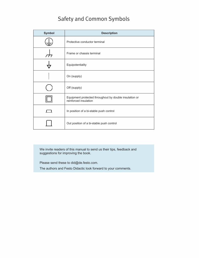
Safety and Common Symbols
Symbol Description
Protective conductor terminal
Frame or chassis terminal
Equipotentiality
On (supply)
Off (supply)
Equipment protected throughout by double insulation or reinforced insulation
In position of a bi-stable push control
Out position of a bi-stable push control
We invite readers of this manual to send us their tips, feedback and suggestions for improving the book.
Please send these to [email protected].
The authors and Festo Didactic look forward to your comments.
III
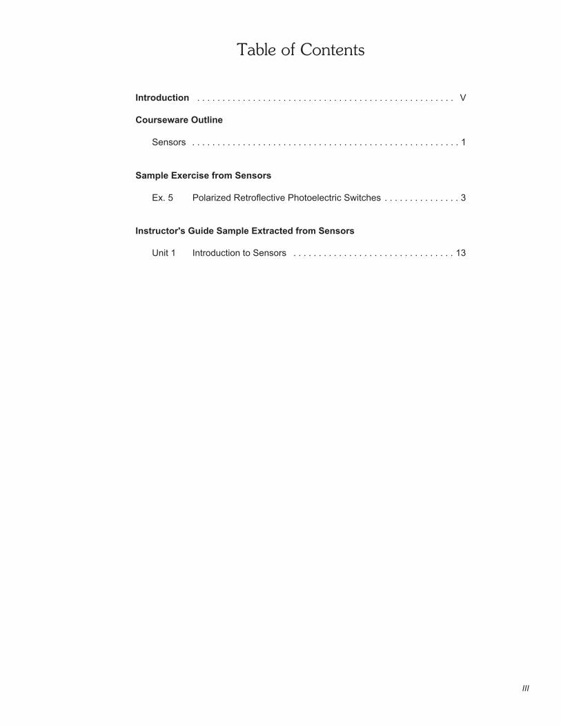
Table of Contents
Introduction . . . . . . . . . . . . . . . . . . . . . . . . . . . . . . . . . . . . . . . . . . . . . . . . . . . V
Courseware Outline
Sensors . . . . . . . . . . . . . . . . . . . . . . . . . . . . . . . . . . . . . . . . . . . . . . . . . . . . . 1
Sample Exercise from Sensors
Ex. 5 Polarized Retroflective Photoelectric Switches . . . . . . . . . . . . . . . 3
Instructor's Guide Sample Extracted from Sensors
Unit 1 Introduction to Sensors . . . . . . . . . . . . . . . . . . . . . . . . . . . . . . . . 13

IV
V
Introduction
The Lab-Volt Sensors Training System, Model 6085, is designed to familiarizestudents with the operation of various sensor types. This training system is as anadd-on to the Electrical Control of Hydraulic Systems, Model 6080-21 and ElectricalControl of Pneumatic Systems, Model 6081-22. It is also available as a stand-alonesystem.
The Sensors Training System contains a selection of photoelectric, inductive andcapacitive sensors representative of what can be found in the industry. Each sensoris mounted on a flexible support attached to a metal base which can be snapped intothe perforations of the Hydraulics and Pneumatics Trainer work surfaces.
The sensor inputs and outputs are accessible through banana jacks for ease ofsystem setup. The sensors are protected against bad connections and reversepolarity, and are identified with the proper symbol on their base. All componentsmeet industrial safety standards.
A wooden block, on which reflectors have been added, is used to observe thecharacteristics of each sensor.
As a stand-alone system, the Sensors Training System includes also a powersupply, pilot lamps, leads and a work surface.
The Sensors courseware consists of a student manual and an instructor guide.

VI
SENSORS
Courseware Outline
VII
Exercise 1 Introduction to Sensors
Introduction to sensors and to the terms commonly used in the sensorfield. Familiarization with the Sensors Training System.
Exercise 2 Diffuse Reflective Photoelectric Switches
Description and operation of diffuse reflective photoelectric switches.Characterization of the switch using a reflective block.
Exercise 3 Background Suppression Photoelectric Switches
Description and operation of background suppression photoelectricswitches. Characterization of the switch using a reflective block.
Exercise 4 Fiber-Optic Photoelectric Switches
Description and operation of fiber-optic photoelectric switches.Characterization of the switch using a reflective block.
Exercise 5 Polarized Retroflective Photoelectric Switches
Description and operation of polarized retroflective photoelectricswitches. Characterization of the switch using a reflective block.
Exercise 6 Capacitive Proximity Switches
Description and operation of capacitive proximity switches.Characterization of the switch using a reflective block.
Exercise 7 Inductive Proximity Switches
Description and operation of induction proximity switches.Characterization of the switch using a reflective block.
Appendices A Equipment Utilization ChartB Sensor Selection GuideC New Terms and WordsD Fiber-Optic Photoelectric SwitchE Hydraulics and Pneumatics ApplicationsF Care of the Sensors Training SystemG Electromagnetic Spectrum
We Value Your Opinion!


Sample Exercise
from
Sensors


3
OBJECTTO BE
E
R
SURFACERETROREFLECTIVE
DETECTED
Exercise 5
Polarized Retroflective Photoelectric Switches
EXERCISE OBJECTIVE
• In this exercise, you will be introduced to polarized retroreflective photoelectricswitches;
• You will learn how and when they are used;• You will also learn their advantages and disadvantages;• You will experiment with their operation using the Reflective Block.
DISCUSSION
Retroreflective, or retroflective, sensing is the most popular sensing mode.Retroreflective sensors can be used to detect most objects, including shiny objects.They contain both the emitter and receiver in the same housing. The light beamemitted by the light source is reflected by a special reflective surface and detectedby the receiver as shown in Figure 5-1. They are intended primarily for use inapplications where an opaque target will completely block the light beam betweenthe sensor and the reflective surface. Therefore, retroreflective sensors are not wellsuited to detect small objects.
Figure 5-1. Retroreflective sensing.
Special reflectors, or reflective tapes, are used for retroreflective sensing. Unlikemirrors, or other flat reflective surfaces, these reflective objects do not require to bealigned perfectly. Misalignment of a reflector, or reflective tape, of up to 15° willtypically not reduce significantly the operating margin of the sensing system. A wideselection of reflectors and reflective tapes are available, some of them are shownin Figure 5-2.

Polarized Retroflective Photoelectric Switches
4
MIRROR
LIGHT RAY
CORNER CUBEREFLECTOR REFLECTOR
GLASS BEAD
OPAQUEMATERIAL
Figure 5-2. Retroreflective materials.
Occasionally, standard retroreflective sensors can be falsely triggered by reflectionsfrom shiny or highly reflective targets. To avoid this, polarized retroreflectivesensing offers a better solution. Polarized retroreflective sensors contain polarizingfilters in front of the emitter and receiver. These filters are perpendicular, or 90° outof phase with each other, as shown in Figure 5-3. Retroreflectors depolarize thelight. Some of the polarized and reflected light passes through the polarizing filterin front of the receiver and is detected by the sensor as shown in Figure 5-3 (a).However, the light reflected by most targets is returned to the sensor with the samepolarity, and cannot pass through the polarizing filter in front of the receiver asshown in Figure 5-3 (b).
Polarized retroreflective sensors offer shorter sensing range than standardretroreflective sensors. Instead of infrared LEDs, they must use a less efficientvisible red LED. There are also additional light losses caused by the polarizingfilters. Many standard reflectors depolarize light and are suitable for polarizedretroreflective sensing. However, corner cube retroreflectors provide the highestsignal return to the sensor. They have 2000 to 3000 times the reflectivity of whitepaper. Therefore, they are used to make safety reflectors for bicycles, cars, andsigns.
As Figure 5-2 shows, corner cube reflectors consist of three adjoining sidesarranged at right angles. When a light ray hits one of the adjoining sides, it isreflected to the second side, then to the third, and then back to its source in adirection parallel to its original course. You can experiment with the corner cubereflection by throwing a tennis ball into the corner of a room. The ball will return toyou after bouncing off the three surfaces. Because of their high level of reflectivity,corner cube reflectors were placed on the moon by the Apollo astronauts and arestill used today to measure the distance to the moon by timing laser light pulsesreflected from earth.
Polarized retroreflective sensors are often used to detect shiny objects. However,because the light may be depolarized as it passes through plastic film or stretchwrap, shiny objects may create detectable reflections (depolarized light) by thereceiver if they are wrapped in clear plastic film.

Polarized Retroflective Photoelectric Switches
5
POLARIZING FILTERS
POLARIZED LIGHT
LENS
POLARIZED LIGHT
DEPOLARIZINGRETROREFLECTOR
EMITTER
RECEIVER
THE RECEIVERRECEIVES LIGHT
(TARGET NOT DETECTED)
RECEIVE LIGHTDOES NOT
THE RECEIVER
R
E
(TARGET DETECTED)
DEPOLARIZED LIGHT
(a)
POLARIZED LIGHT
POLARIZEDLIGHT
(b)
TARGET
Figure 5-3. Polarized retroreflective sensing.
Most reflective tapes, like glass bead retroreflectors, do not depolarize light and aresuitable only for use with standard retroreflective sensors.
Polarized Retroflective Photoelectric Switches
6
(−)
(+)
CIRCUITMAIN
LADDER DIAGRAM SYMBOL
COMMON
NO TERMINAL
NC TERMINAL
TERMINAL
1
2
3CR
CR
CR
1
2
3
L3L2
L1 : POWER
L2 : OUTPUT
ELECTRICAL DIAGRAM
L1
L3 : STABILITY
STABILITY (ORANGE LED)
OUTPUT (YELLOW LED)
POWER (GREEN LED)
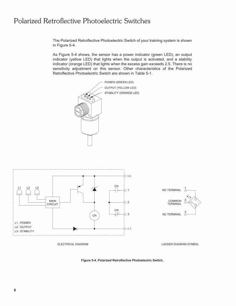
The Polarized Retroflective Photoelectric Switch of your training system is shownin Figure 5-4.
As Figure 5-4 shows, the sensor has a power indicator (green LED), an outputindicator (yellow LED) that lights when the output is activated, and a stabilityindicator (orange LED) that lights when the excess gain exceeds 2.5. There is nosensitivity adjustment on this sensor. Other characteristics of the PolarizedRetroflective Photoelectric Switch are shown in Table 5-1.
Figure 5-4. Polarized Retroflective Photoelectric Switch.

Polarized Retroflective Photoelectric Switches
7
CHARACTERISTICS OF THE POLARIZED RETROFLECTIVE PHOTOELECTRIC SWITCH
Type Polarized retroreflective
Transistor output type Sourcing (PNP)
Sensing distance Maximum 3 m (9.8 ft)
Light source TypeWavelength
Visible red660 nm (26.0 micro-inch)
Response time (sensor only) 1 ms
Light beam detection modes Light operate/Dark operate*
Sensor output type Relay output
* The sensor has light operate and dark operate outputs. The outputrelay coil is connected to the light operate output. The dark operateoutput is not used.
Table 5-1. Characteristics of the Polarized Retroflective Photoelectric Switch.
Procedure Summary
In the first part of the exercise, Characteristics, you will observe the ability of thePolarized Retroflective Photoelectric Switch to detect each surface of the ReflectiveBlock.
In the second part of the exercise, Detection of various objects, you will observe theability of the Polarized Retroflective Photoelectric Switch to detect the presence ofopaque, transparent and small objects.
EQUIPMENT REQUIRED
Refer to the Equipment Utilization Chart, in Appendix A of this manual, to obtain thelist of equipment required to perform this exercise.
PROCEDURE
Characteristics
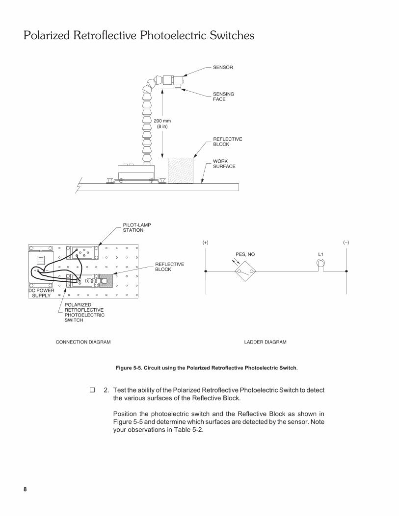
1. Connect the circuit shown in Figure 5-5, and turn on the DC Power Supply.
Polarized Retroflective Photoelectric Switches
8
CONNECTION DIAGRAM
DC POWER
LADDER DIAGRAM
(+) (−)
L1
SUPPLY
RETROFLECTIVEPOLARIZED
+
PILOT-LAMPSTATION
PES, NO
PHOTOELECTRICSWITCH
BLOCKREFLECTIVE
200 mm(8 in)
SENSOR
SENSINGFACE
REFLECTIVE
WORKSURFACE
BLOCK
Figure 5-5. Circuit using the Polarized Retroflective Photoelectric Switch.
2. Test the ability of the Polarized Retroflective Photoelectric Switch to detectthe various surfaces of the Reflective Block.
Position the photoelectric switch and the Reflective Block as shown inFigure 5-5 and determine which surfaces are detected by the sensor. Noteyour observations in Table 5-2.

Polarized Retroflective Photoelectric Switches
9
SURFACE DETECTED NOT DETECTED
Black Wooden Surface
White Wooden Surface
Matte Black Metallic Surface
Shiny Metallic Surface
Retroreflective Surface
Table 5-2.
3. What can you conclude from your observations?
Detection of various objects
4. Position the Reflective Block so that the retroreflective surface is on top.
Pass your fingers between the photoelectric switch and the ReflectiveBlock. Does the photoelectric switch detect their presence? What does thismean?
5. Is lamp L1 lit when the photoelectric switch detects the presence of anobject between the sensing face and the retroreflective surface? Explainwhy.

Polarized Retroflective Photoelectric Switches
10
6. Pass a transparent object between the sensor and the Reflective Block.Does the photoelectric switch detect its presence? What does this mean?
7. Pass a small object like an electrical lead between the sensor and theReflective Block. Does the photoelectric switch detect its presence? Whatdoes this mean?
8. Without modifying the sensor position, take the Reflective Block in yourhand and hold the retroreflective surface in front of the sensing face withan angle of approximately 45°. Does the photoelectric switch detect itspresence in this position? What does this indicate?
9. Turn off the DC Power Supply, and remove all leads.
CONCLUSION
In this exercise, you were introduced to polarized retroreflective photoelectricswitches. You learned how and when they are used, their advantages anddisadvantages.
You observed how the Polarized Retroflective Photoelectric Switch detects thepresence of various objects placed between the sensor and the retroreflectivesurface of the Reflective Block. You saw that this photoelectric switch does notdetect transparent objects. You also observed that it does not detect either objectssmaller than the light beam.
Polarized Retroflective Photoelectric Switches
11
REVIEW QUESTIONS
1. For which applications are the retroreflective photoelectric sensors designedfor?
2. Name two reasons why polarized retroreflective sensors offer a shorterdistance than standard retroreflective sensors.
3. What is the purpose of the filters in a polarized retroreflective sensor?
4. Name the type of retroreflector that provides the highest signal return.
5. Explain why retroreflective sensors are not well suited to detect small objects.


Instructor Guide Sample
Extracted from
Sensors


Sensors
15
SHINY METALLIC SURFACE
MATTE BLACK METALLIC SURFACE
UNDERSIDE
RETROREFLECTIVE SURFACE
BLACK WOODEN SURFACEWHITE WOODEN SURFACE
EXERCISE 1 INTRODUCTION TO SENSORS
ANSWERS TO PROCEDURE QUESTIONS
1.
PHOTOELECTRIC SENSORS VISIBLE RED INFRARED
Diffuse Reflective Photoelectric Switch Model 6377
Background Suppression Photoelectric SwitchModel 6373
Fiber-Optic Photoelectric Switch Model 6378
Polarized Retroflective Photoelectric Switch Model 6374
Table 1-1. Visible Red and Infrared Light Beams.
3.
Figure 1-5. Development view of the Reflective Block.
Sensors
16
6. Yes
7. Yes. Lamp L1 is lit when an object is placed against the sensing face of theCapacitive Proximity Switch. When the sensor detects the presence of anobject, current flows through the relay coil, the magnetic core and armatureattract each other, causing the armature to move toward the core. Thisswitches the relay contacts to the activated mode, causing lamp L1 to light.
8. When lamp L1 turns on, lamp L2 turns off. When the sensor detects thepresence of an object, current flows through the relay coil. This switchesthe NC relay contacts to the activated mode, causing lamp L2 to turn off.
ANSWERS TO REVIEW QUESTIONS
1. They use a light beam to sense the presence or motion of objects.
2. Light sensing means the receiver detects the presence of the light beam, whiledark sensing means the receiver detects the absence of the light beam.
3. Diffuse-reflective, through-beam and retroreflective.
4. The excess gain ratio is the ratio of light intensity available at a given distanceof a sensor to the light intensity needed to trigger the sensor.
5. Hysteresis is the difference between the "operate point" and "release point".