fluid mechanics and applications inter american chapter 6 meen 3110 – fluid mechanics and...
TRANSCRIPT
Flu
id M
ech
an
ics
an
d A
pp
licati
on
s
In
ter
Am
eri
can
Flu
id M
ech
an
ics
an
d A
pp
licati
on
s
In
ter
Am
eri
can
ChapterChapter
6MEEN 3110 – Fluid Mechanics and Applications
Fall - 2010
Lecture 06
LOSSES IN PIPE SYSTEMS
6. Losses in Pipe Systems Flu
id M
ech
an
ics
an
d A
pp
licati
on
s
In
ter
Am
eri
can
Flu
id M
ech
an
ics
an
d A
pp
licati
on
s
In
ter
Am
eri
can Chapter Objectives
Up on completion of this lecture, the student will be able to: To study and evaluate pressure losses due to
viscous (frictional) effects in fluid flows through pipes, valves and other fittings following these tasks: To determine and plot the values of head loss as a
function of volume flow rate. Plot the values of friction factor as a function of
Reynolds Number.
6. Losses in Pipe Systems Flu
id M
ech
an
ics
an
d A
pp
licati
on
s
In
ter
Am
eri
can
Flu
id M
ech
an
ics
an
d A
pp
licati
on
s
In
ter
Am
eri
can 6.1 Theory
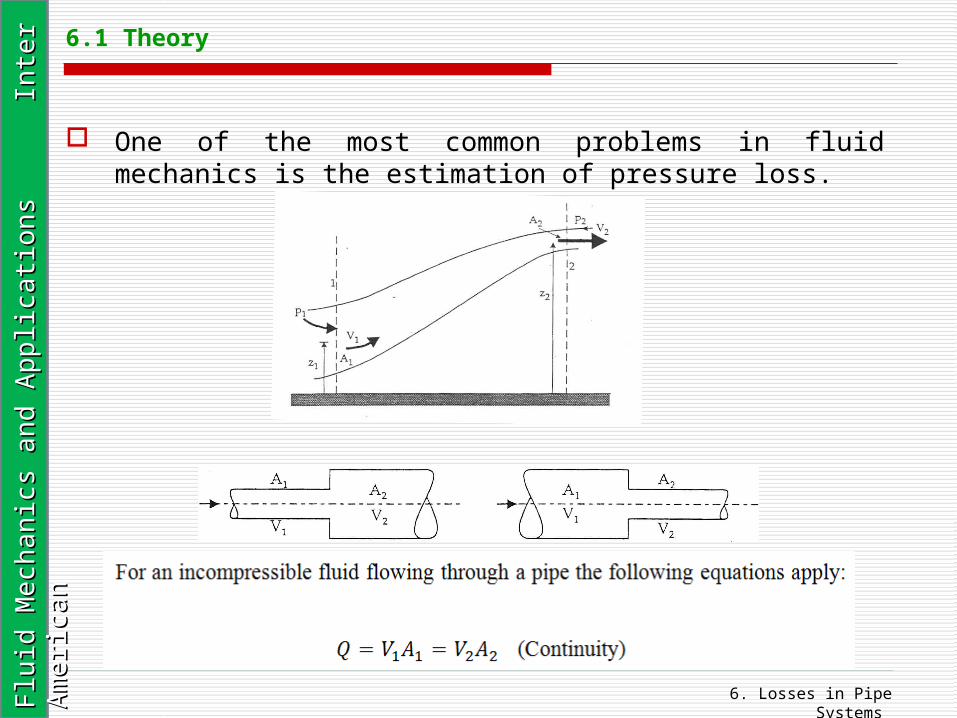
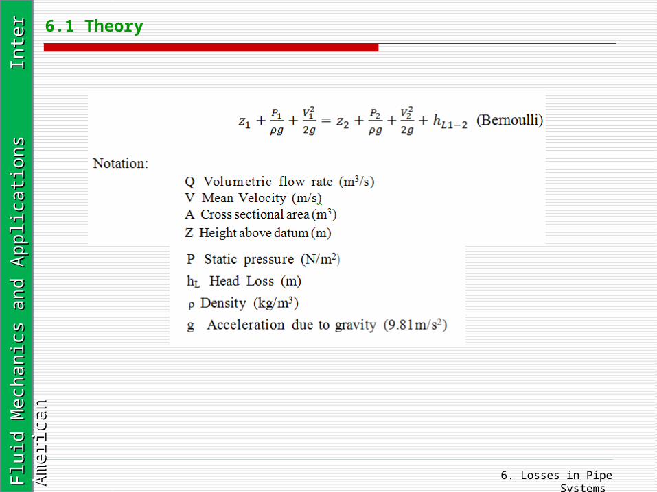
One of the most common problems in fluid mechanics is the estimation of pressure loss.
6. Losses in Pipe Systems Flu
id M
ech
an
ics
an
d A
pp
licati
on
s
In
ter
Am
eri
can
Flu
id M
ech
an
ics
an
d A
pp
licati
on
s
In
ter
Am
eri
can 6.1 Theory
6. Losses in Pipe Systems Flu
id M
ech
an
ics
an
d A
pp
licati
on
s
In
ter
Am
eri
can
Flu
id M
ech
an
ics
an
d A
pp
licati
on
s
In
ter
Am
eri
can 6.1 Theory
Head Loss The head loss in a pipe circuit falls into two categories: That due to viscous resistance extending throughout
the total length of the circuit, and; That due to localized effects such as valves,
sudden changes in area of flow, and bends.
The overall head loss is a combination of both these categories. Because of mutual interference between neighboring components in a complex circuit the total head loss may differ from that estimated from the losses due to the individual components considered in isolation.
6. Losses in Pipe Systems Flu
id M
ech
an
ics
an
d A
pp
licati
on
s
In
ter
Am
eri
can
Flu
id M
ech
an
ics
an
d A
pp
licati
on
s
In
ter
Am
eri
can 6.1 Theory
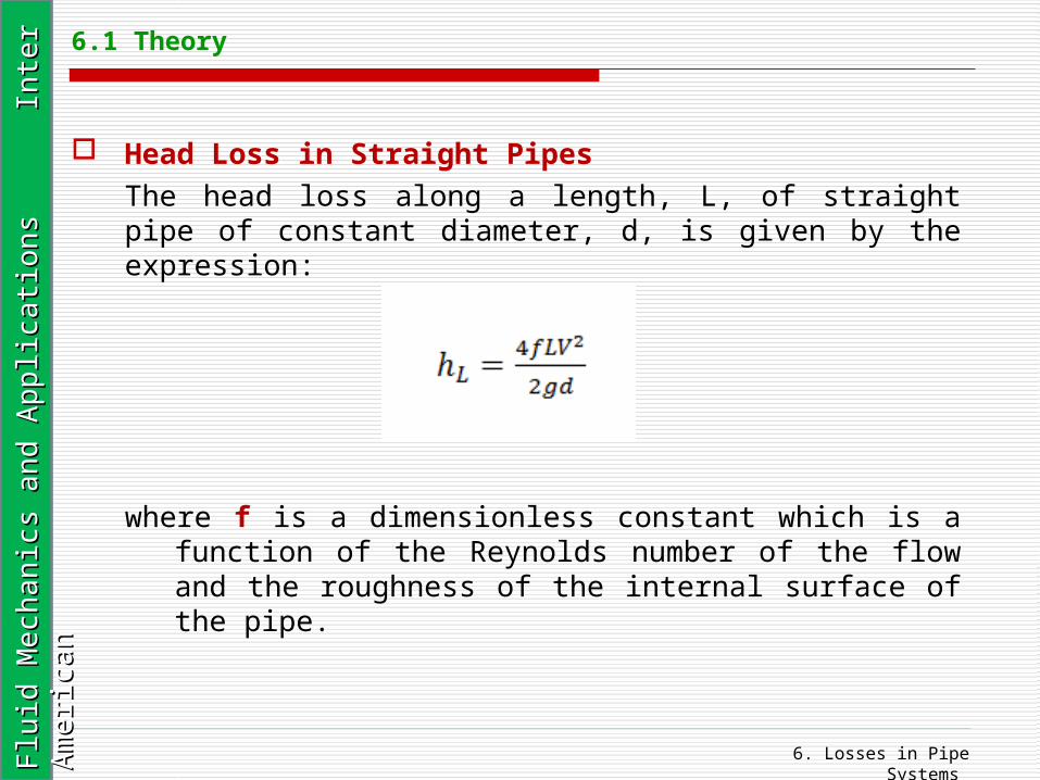
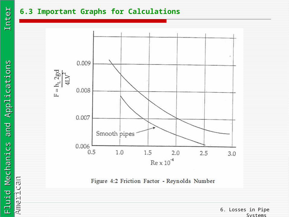
Head Loss in Straight Pipes The head loss along a length, L, of straight pipe of constant diameter, d, is given by the expression:
where f is a dimensionless constant which is a function of the Reynolds number of the flow and the roughness of the internal surface of the pipe.

6. Losses in Pipe Systems Flu
id M
ech
an
ics
an
d A
pp
licati
on
s
In
ter
Am
eri
can
Flu
id M
ech
an
ics
an
d A
pp
licati
on
s
In
ter
Am
eri
can 6.1 Theory
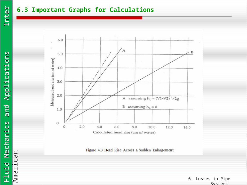
Head Loss due to Sudden Changes in Area of FlowSudden Expansion: The head loss at a sudden expansion is given by the expression:
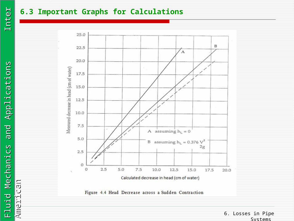
Sudden Contraction: The head loss at a sudden contraction is given by the expression:
6. Losses in Pipe Systems Flu
id M
ech
an
ics
an
d A
pp
licati
on
s
In
ter
Am
eri
can
Flu
id M
ech
an
ics
an
d A
pp
licati
on
s
In
ter
Am
eri
can 6.1 Theory
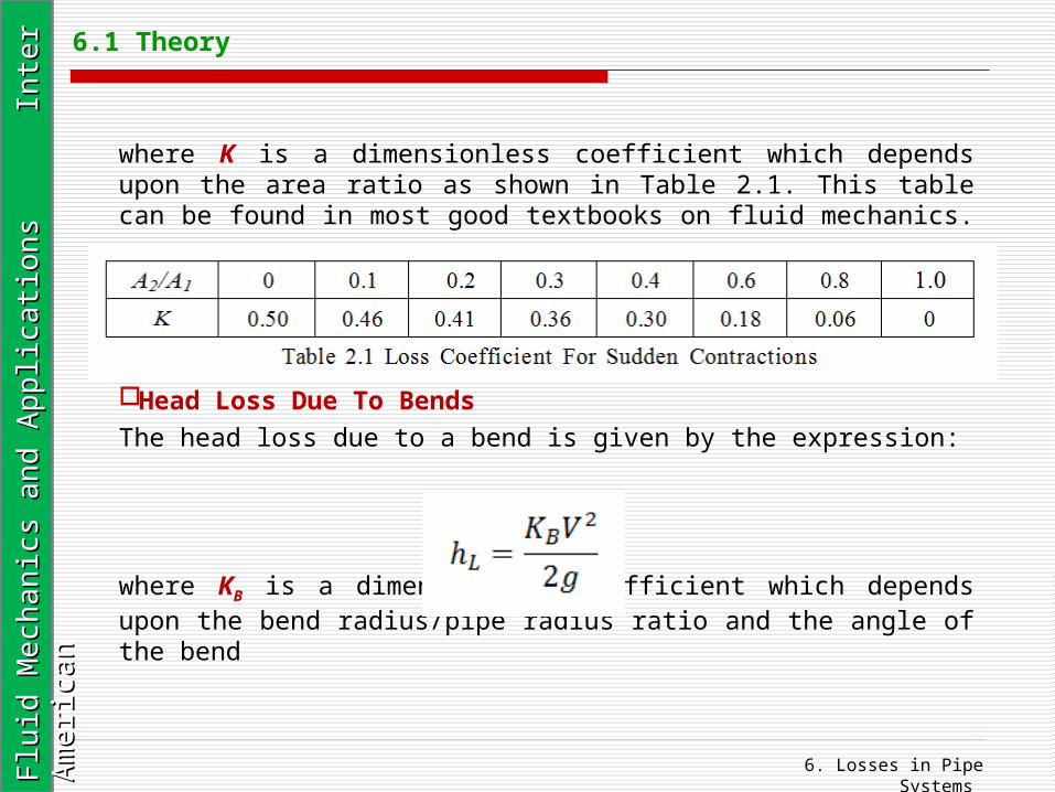
where K is a dimensionless coefficient which depends upon the area ratio as shown in Table 2.1. This table can be found in most good textbooks on fluid mechanics.
Head Loss Due To Bends The head loss due to a bend is given by the expression:
where KB is a dimensionless coefficient which depends upon the bend radius/pipe radius ratio and the angle of the bend
6. Losses in Pipe Systems Flu
id M
ech
an
ics
an
d A
pp
licati
on
s
In
ter
Am
eri
can
Flu
id M
ech
an
ics
an
d A
pp
licati
on
s
In
ter
Am
eri
can 6.1 Theory
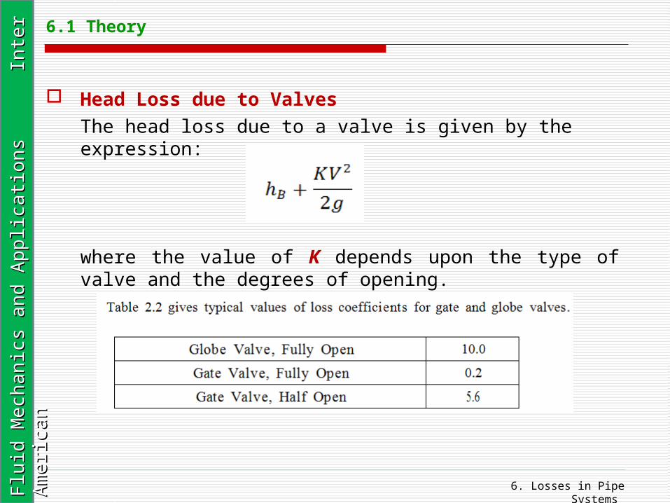
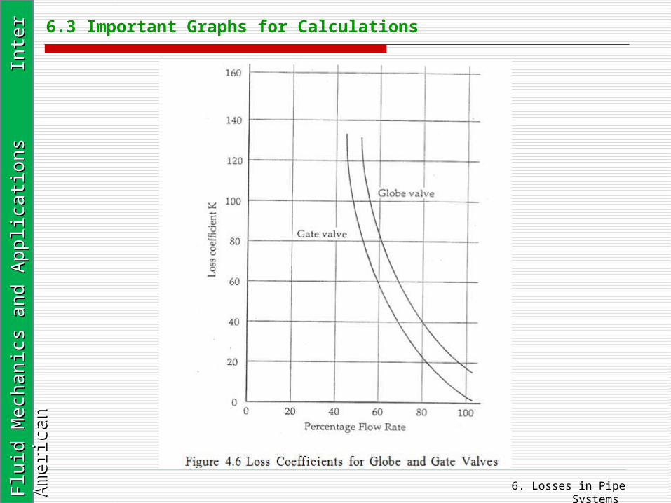
Head Loss due to Valves The head loss due to a valve is given by the expression:
where the value of K depends upon the type of valve and the degrees of opening.
6. Losses in Pipe Systems Flu
id M
ech
an
ics
an
d A
pp
licati
on
s
In
ter
Am
eri
can
Flu
id M
ech
an
ics
an
d A
pp
licati
on
s
In
ter
Am
eri
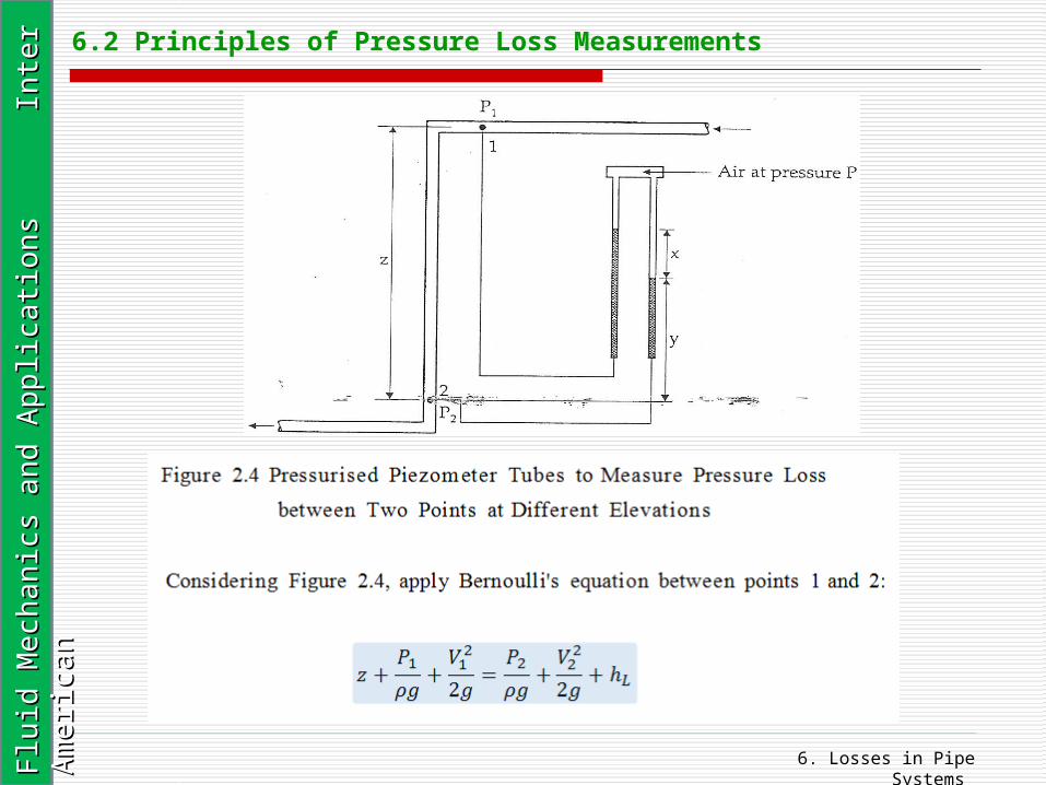
can 6.2 Principles of Pressure Loss Measurements
6. Losses in Pipe Systems Flu
id M
ech
an
ics
an
d A
pp
licati
on
s
In
ter
Am
eri
can
Flu
id M
ech
an
ics
an
d A
pp
licati
on
s
In
ter
Am
eri
can 6.2 Principles of Pressure Loss Measurements
6. Losses in Pipe Systems Flu
id M
ech
an
ics
an
d A
pp
licati
on
s
In
ter
Am
eri
can
Flu
id M
ech
an
ics
an
d A
pp
licati
on
s
In
ter
Am
eri
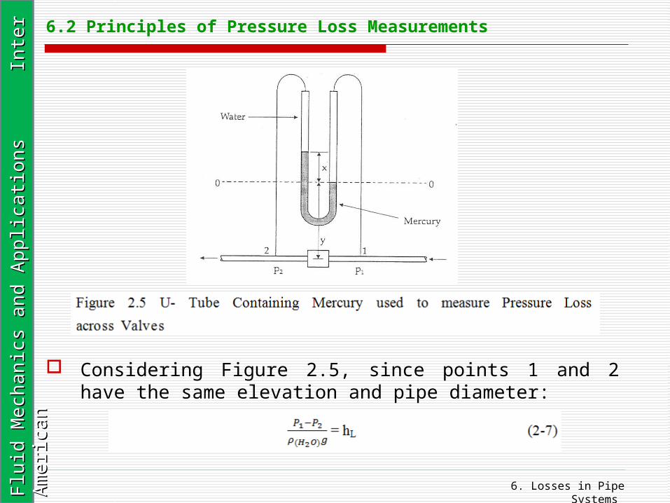
can 6.2 Principles of Pressure Loss Measurements
Considering Figure 2.5, since points 1 and 2 have the same elevation and pipe diameter:
6. Losses in Pipe Systems Flu
id M
ech
an
ics
an
d A
pp
licati
on
s
In
ter
Am
eri
can
Flu
id M
ech
an
ics
an
d A
pp
licati
on
s
In
ter
Am
eri
can 6.2 Principles of Pressure Loss Measurements

6. Losses in Pipe Systems Flu
id M
ech
an
ics
an
d A
pp
licati
on
s
In
ter
Am
eri
can
Flu
id M
ech
an
ics
an
d A
pp
licati
on
s
In
ter
Am
eri
can 6.3 Important Graphs for Calculations
6. Losses in Pipe Systems Flu
id M
ech
an
ics
an
d A
pp
licati
on
s
In
ter
Am
eri
can
Flu
id M
ech
an
ics
an
d A
pp
licati
on
s
In
ter
Am
eri
can 6.3 Important Graphs for Calculations
6. Losses in Pipe Systems Flu
id M
ech
an
ics
an
d A
pp
licati
on
s
In
ter
Am
eri
can
Flu
id M
ech
an
ics
an
d A
pp
licati
on
s
In
ter
Am
eri
can 6.3 Important Graphs for Calculations
6. Losses in Pipe Systems Flu
id M
ech
an
ics
an
d A
pp
licati
on
s
In
ter
Am
eri
can
Flu
id M
ech
an
ics
an
d A
pp
licati
on
s
In
ter
Am
eri
can 6.3 Important Graphs for Calculations
6. Losses in Pipe Systems Flu
id M
ech
an
ics
an
d A
pp
licati
on
s
In
ter
Am
eri
can
Flu
id M
ech
an
ics
an
d A
pp
licati
on
s
In
ter
Am
eri
can 6.3 Important Graphs for Calculations
6. Losses in Pipe Systems Flu
id M
ech
an
ics
an
d A
pp
licati
on
s
In
ter
Am
eri
can
Flu
id M
ech
an
ics
an
d A
pp
licati
on
s
In
ter
Am
eri
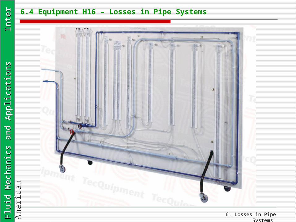
can 6.4 Equipment H16 – Losses in Pipe Systems
6. Losses in Pipe Systems Flu
id M
ech
an
ics
an
d A
pp
licati
on
s
In
ter
Am
eri
can
Flu
id M
ech
an
ics
an
d A
pp
licati
on
s
In
ter
Am
eri
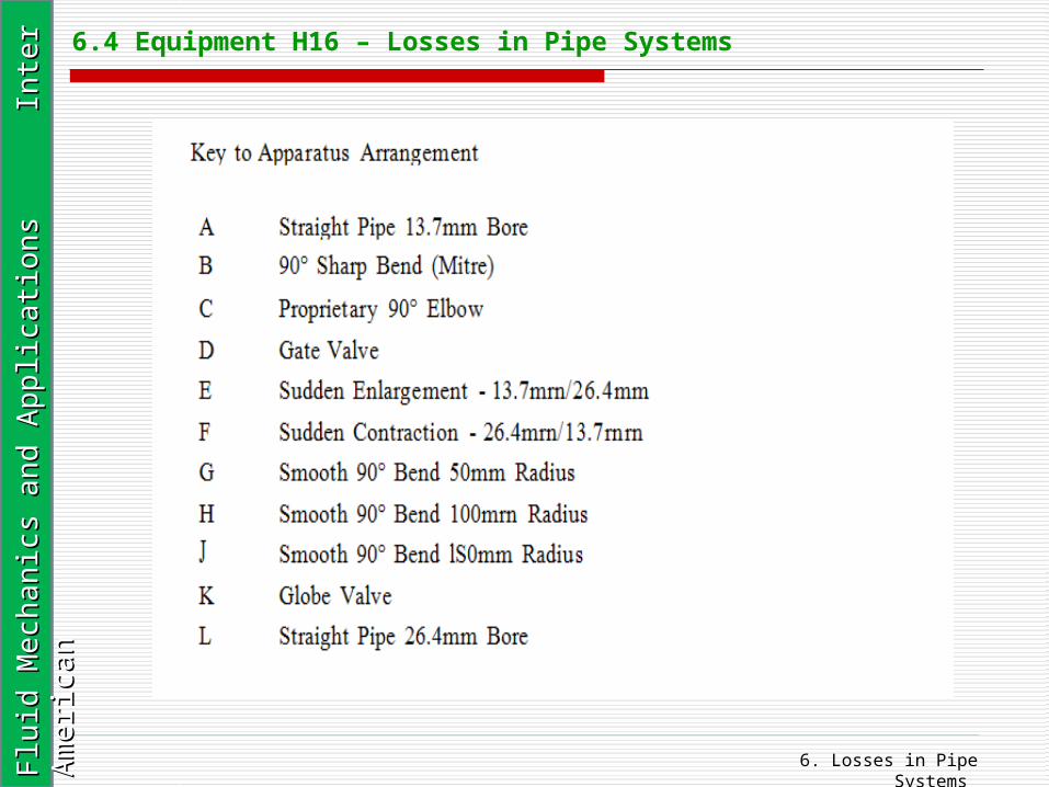
can 6.4 Equipment H16 – Losses in Pipe Systems