flow measurement for densphase conveying
TRANSCRIPT
SWR engineering Messtechnik GmbH
EN
DensFlow DFlow Measurement forDensphase Conveying
Ope
rati
ng In
stru
ctio
ns

Operating Instructions
2
Contents Page
1. System Overview . . . . . . . . . . . . . . . . . . . . . . . . . . . . . . . . . . . . . . . . . . . . . . . . . . . . . . . . . . . . . . . . . . . . . . 3
2. Function . . . . . . . . . . . . . . . . . . . . . . . . . . . . . . . . . . . . . . . . . . . . . . . . . . . . . . . . . . . . . . . . . . . . . . . . . . . . . 3
3. Safety . . . . . . . . . . . . . . . . . . . . . . . . . . . . . . . . . . . . . . . . . . . . . . . . . . . . . . . . . . . . . . . . . . . . . . . . . . . . . . . 4
3.1 Regular Use . . . . . . . . . . . . . . . . . . . . . . . . . . . . . . . . . . . . . . . . . . . . . . . . . . . . . . . . . . . . . . . . . . . . . . 4
3.2 Identification of Dangers . . . . . . . . . . . . . . . . . . . . . . . . . . . . . . . . . . . . . . . . . . . . . . . . . . . . . . . . . . . 4
3.3 Operational Safety . . . . . . . . . . . . . . . . . . . . . . . . . . . . . . . . . . . . . . . . . . . . . . . . . . . . . . . . . . . . . . . . . 4
3.4 Technical Progress . . . . . . . . . . . . . . . . . . . . . . . . . . . . . . . . . . . . . . . . . . . . . . . . . . . . . . . . . . . . . . . . . 4
4. Mounting and Installation . . . . . . . . . . . . . . . . . . . . . . . . . . . . . . . . . . . . . . . . . . . . . . . . . . . . . . . . . . . . . . 5
4.1 Delivery Range . . . . . . . . . . . . . . . . . . . . . . . . . . . . . . . . . . . . . . . . . . . . . . . . . . . . . . . . . . . . . . . . . . . . 5
4.2 Auxiliary . . . . . . . . . . . . . . . . . . . . . . . . . . . . . . . . . . . . . . . . . . . . . . . . . . . . . . . . . . . . . . . . . . . . . . . . . . 5
4.3 Mounting of the Measuring Pipe . . . . . . . . . . . . . . . . . . . . . . . . . . . . . . . . . . . . . . . . . . . . . . . . . . . . . 5
4.4 Overview of the Connection of the Sensor Pipe and Evaluation Unit . . . . . . . . . . . . . . . . . . . . . . 7
5. Electrical Connection . . . . . . . . . . . . . . . . . . . . . . . . . . . . . . . . . . . . . . . . . . . . . . . . . . . . . . . . . . . . . . . . . . 8
5.1 Version Field Housing . . . . . . . . . . . . . . . . . . . . . . . . . . . . . . . . . . . . . . . . . . . . . . . . . . . . . . . . . . . . . . . 8
5.2 Version 19” Rack Mounted Transmitter . . . . . . . . . . . . . . . . . . . . . . . . . . . . . . . . . . . . . . . . . . . . . . . 9
6. Commissioning . . . . . . . . . . . . . . . . . . . . . . . . . . . . . . . . . . . . . . . . . . . . . . . . . . . . . . . . . . . . . . . . . . . . . . . 10
7. Standard Display of DensFlow D . . . . . . . . . . . . . . . . . . . . . . . . . . . . . . . . . . . . . . . . . . . . . . . . . . . . . . . . 12
8. Structure Main Menu DensFlow D . . . . . . . . . . . . . . . . . . . . . . . . . . . . . . . . . . . . . . . . . . . . . . . . . . . . . . 13
9. System Adjustments in Detail . . . . . . . . . . . . . . . . . . . . . . . . . . . . . . . . . . . . . . . . . . . . . . . . . . . . . . . . . . . 15
10. Connection Examples . . . . . . . . . . . . . . . . . . . . . . . . . . . . . . . . . . . . . . . . . . . . . . . . . . . . . . . . . . . . . . . . . 24
11. Warranty . . . . . . . . . . . . . . . . . . . . . . . . . . . . . . . . . . . . . . . . . . . . . . . . . . . . . . . . . . . . . . . . . . . . . . . . . . . . 25
12. Trouble Shooting . . . . . . . . . . . . . . . . . . . . . . . . . . . . . . . . . . . . . . . . . . . . . . . . . . . . . . . . . . . . . . . . . . . . . 25
13. Technical Data . . . . . . . . . . . . . . . . . . . . . . . . . . . . . . . . . . . . . . . . . . . . . . . . . . . . . . . . . . . . . . . . . . . . . . . 26

Operating Instructions
3
1. System Overview
A DensFlow D-Measuring system consists of the following components:
Fig. 2: Coupling of the electromagnetic waves
2. Function • DensFlow D is a measuring system especially developed for the measurement of high flow rates in dens
phase conditions.
• DensFlow D is working according to the latest microprocessor technology. By special capacitive linking of an electromagnetic wave a homogeneous measuring field is produced in the pipe.
• The electromagnetic wave brought into the pipe is reciprocally acting with the solid particles. These signals are evaluated in frequency and amplitude.
• The measurement of the solid speed is done by means of correlation. Two sensors are used for the generation of the correlation signals.
• A complete measuring unit consists of the sensor (measuring pipe) and the evaluation unit.
Sensor Evaluation Unit+Feuchte13,47 %

Operating Instructions
4
3. Safety
The measuring system DensFlow D was designed, built and tested to be safe and was shipped in safe condition. Nevertheless persons or objects may be endangered by components of the system if these are operated in an inexpert manner. Therefore the operational instructions must be read completely and the safety notes must be followed.In case of inexpert or irregular use, the manufacturer will refuse any liability or guarantee.
3.1 Regular Use
• The measuring system must be installed for measuring the flow rate only. Other usage and modifications of the measuring system are not permitted.
• Only original spare parts and accessories of SWR engineering must be used.
3.2 Identification of Dangers
• Possible dangers when using the measuring system are marked by the following symbols in the operating instructions:
Warning! • This symbol in the operating instructions marks actions, which may represent a danger for life and limb
of persons when carried out in an inexpert manner.
Attention! • All actions which may endanger objects are marked with this symbol in the operating instructions.
3.3 Operational Safety
• The measuring system must be installed by trained and authorised personnel only. • Switch off the supply voltage for all maintenance, cleaning or inspection works on the tubes or on
components of the DensFlow D. Follow the notes of the chapter maintenance. • The components and electrical connections must be checked for damages regularly. If a damage is
found, it is to be repaired before further operation of the instruments.
• Before hot-work the sensor must be removed from the piping.
3.4 Technical Progress
• The manufacturer reserves the right to adapt technical data to the technical progress without particular advance notice. If you have any questions, SWR engineering will be pleased to inform you on possible changes and extensions of the operating instructions.

Operating Instructions
5
4. Mounting and Installation
4.1 Delivery Range
• Measuring instrument in a field housing or in a 19” rack mounted transmitter
• Sensor for installation into the pipe
• Operating instructions
4.2 Auxiliary
• Appropriate wrench or ring wrench for screwing
• Tools for adjusting the wiring
4.3 Mounting of the Measuring Pipe
The sensor has to be mounted as follows:
• Determine the place of mounting on the pipe. The mounting has to be in a vertical position!
• Follow the necessary distances of valves, bows, fans or cellular wheel sluices etc. and also other measurement devices like temperature and pressure etc. to the sensor (see Fig. 3).
Fig. 3: Minimal distances of the sensor to pipe bends and baffles

Operating Instructions
6
Attention!
• Before installation it has to be checked that no fin, mismatch or seals are inside the pipe. It is important to remove any resistors affecting the flow.
Fig. 5: Evaluation unit
Fig. 4: Build in of sensor
• It is possible to mount the evaluation unit up to 300 m away from the sensor.
or

Operating Instructions
7
Fig. 6: Wiring of the sensor pipe and evaluation unit
A maximum length of 300 m of the sensor cable should not be exceeded.A 4-wired shielded cable is needed between sensor and evaluation unit.
4.4 Overview of the Connection of the Sensor Pipe and Evaluation Unit
Fig. 7: Wiring of the sensor pipe and evaluation unit 19” version

Operating Instructions
8
Fig. 8: Electrical Connection
L N PEI-in 1Na Na
I-out 1+ -
I-out 2 I-out 3 Alarm Relay
NO C NCD-out RS 485
A B GND
D-in 1 D-in 2 Sensor+ - A B Shield+ - + - + - + -+ -
5. Electrical Connection
5.1 Version Field Housing
Evaluation UnitTerminal No. ConnectionConnection of the Supply VoltageL / +24 V Input Supply Voltage 230 V / 50 Hz, 110 V / 60 Hz (optional 24 V DC)N / 0 V Input Supply Voltage 230 V / 50 Hz, 110 V / 60 Hz (optional 24 V DC)PE Protective EarthConnections
I-in 1 Na not availableNa not available
I-out 1+ Current Output 4 ... 20 mA +
Flow- Current Output 4 ... 20 mA - (GND)
I-out 2+ Current Output 4 ... 20 mA +
Density- Current Output 4 ... 20 mA - (GND)
I-out 3+ Current Output 4 ... 20 mA +
Velocity- Current Output 4 ... 20 mA - (GND)
Alarm Relay
NO Isolated Relay Contact NO (make contact)C Isolated Relay Contact COM (common contact)
NC Isolated Relay Contact NC (break contact)
D-out+ Digital Output (+)- Digital Output (-)
RS 485A RS 485 Interface Data A (+)B RS 485 Interface Data B (-)
GND RS 485 Interface Ground
D-in 1+ Digital Interface 1 (+)- Digital Interface 1 (-)
D-in 2+ Digital Interface 2 (+)- Digital Interface 2 (-)
Sensor
+ Supply Voltage 24 V (+) Cable No. 1- Supply Voltage GND Cable No. 2A RS 485 Data A Cable No. 3B RS 485 Data B Cable No. 4
Shield Shield Shield

Operating Instructions
9
5.2 Version 19” Rack Mounted Transmitter
Fig. 9: Electrical Connection
TransmitterTerminal FunctionConnection of Power Supply+ 24 V DC 2 a/c + 4 a/c Input Power Supply + 24 V DC0 V GND 6 a/c + 8 a/c Input Power Supply GNDPE 30 a/c Protective EarthTerminalsRS 485 System / PC
10 a RS 485 Interface Data A (+)12 a RS 485 Interface Data B (-)
Relay NO14 a Relay Contact 114 c Relay Contact 2
Current Output 1 Flow Rate16 a 4 ... 20 mA I-out 1 (-)16 c 4 ... 20 mA I-out 1 (+)
Current Output 2 Density18 a 4 ... 20 mA I-out 2 (-)18 c 4 ... 20 mA I-out 2 (+)
Current Output 3 Velocity20 a 4 ... 20 mA I-out 3 (-)20 c 4 ... 20 mA I-out 3 (+)
Digital Input 122 a Dig. In 1 (-)22 c Dig. In 1 (+)
Digital Input 224 a Dig. In 2 (-)24 c Dig. In 2 (+)
Impulse Output26 a Dig. Out (-)26 c Dig. Out (+)
Sensor Connections
28 a/c Output Power Supply 24 V DC32 a/c Output Power Supply 0 V GND10 c Output RS 485 Interface Data A (+)12 c Output RS 485 Interface Data B (-)
Operating Instructions
10
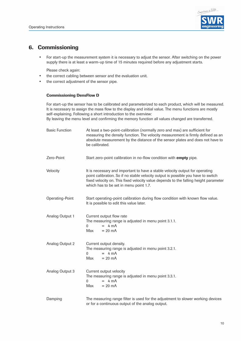
6. Commissioning
• For start-up the measurement system it is necessary to adjust the sensor. After switching on the power supply there is at least a warm-up time of 15 minutes required before any adjustment starts.
Please check again: • the correct cabling between sensor and the evaluation unit. • the correct adjustment of the sensor pipe.
Commissioning DensFlow D
For start-up the sensor has to be calibrated and parameterized to each product, which will be measured. It is necessary to assign the mass flow to the display and initial value. The menu functions are mostly self-explaining. Following a short introduction to the overview:By leaving the menu level and confirming the memory function all values changed are transferred.
Basic Function At least a two-point-calibration (normally zero and max) are sufficient for measuring the density function. The velocity measurement is firmly defined as an absolute measurement by the distance of the sensor plates and does not have to be calibrated.
Zero-Point Start zero-point calibration in no-flow condition with empty pipe.
Velocity It is necessary and important to have a stable velocity output for operating point calibration. So if no stable velocity output is possible you have to switch fixed velocity on. This fixed velocity value depends to the falling height parameter which has to be set in menu point 1.7.
Operating-Point Start operating-point calibration during flow condition with known flow value. It is possible to edit this value later.
Analog Output 1 Current output flow rate The measuring range is adjusted in menu point 3.1.1. 0 = 4 mA Max = 20 mA
Analog Output 2 Current output density. The measuring range is adjusted in menu point 3.2.1. 0 = 4 mA Max = 20 mA
Analog Output 3 Current output velocity The measuring range is adjusted in menu point 3.3.1. 0 = 4 mA Max = 20 mA
Damping The measuring range filter is used for the adjustment to slower working devices or for a continuous output of the analog output.

Operating Instructions
11
To enable DensFlow D for calculation a flow rate the following suppositions have to be given:
• Stable working velocity measurement resp. fixed velocity if a stable velocity measurement is not possible due to bad conveying conditions.
• Density measurement
As the operating-point calibration needs a stable velocity measurement too, within the first commissioning you have to take care for this. Therefore some hints:
• During flow the RMS values of the velocity signals have to be obvious higher than the noise level (NST, no signal threshold). There is no exact defined range, but, experienced values are about 1000 to 3000. If NST is now 500 or smaller a safe operating condition should be possible.
• If velocity still fails, caused of bad conveying conditions, fixed velocity has to be activated. Therefore the parameter “falling height” has to be set, the system will calculate with this value an averaged velocity of fall. Also important in this context is the NST level (see standard display / V - velocity / S - speed adjustment / point 1. threshold). This level will now work like switch, RMS values above NST level will switch velocity on, values below will switch velocity to zero.

Operating Instructions
12
7. Standard Display of DensFlow D
The standard display shows the actual flow rate as well as measuring values of density, velocity and the totaliser value.
With four switch pads you are able to further information and configuration windows:
R Reset totaliser, choose OK or NO
D Density, further informations about density measurement, back with M (mass flow)
V Velocity, further information about speed measurement, back with M or press S (speed) for velocity configuration.
S V-Adjustment, various settings for speed measurement. 1. Threshold It defines the noise level of the RMS values (root mean square values) of the velocity signals. All values below will be ignored for speed measurement resp. with activated fix-velocity the output will switch to 0 m/s. Possible values 1 - 65535, cancel with E (ESC)
2. Display of the actual RMS value of velocity signals
3. Fix-velocity Setting of fix-velocity value, this will replace automatically the parameter falling height. Possible values 1 - 99.99, cancel with E (ESC)
4. Vfix Fix-Velocity On / Off
T Displays the electronics temperature
V-Adjustment 7 8 9Threshold
4 5 6230 1 2 3
Eff-Value =E 0 8135
V-Adjustment 7 8 9Fix-Velocity
4 5 62.30 m/s
1 2 3E 0 8

Operating Instructions
13
8. Structure Main Menu DensFlow D
Switch to main menu: Press any pad of the touchscreen for about 5 s until the menu appears.
1. Measurement
1.1 Tag Name (10 characters)
1.2 Unit Select: g / kg / t
1.3 Time Unit Select: h / min / s
1.4 Dec. Point Position of dec. point
1.5 Density Range 1 --- 3000 g/l
1.6 Aperture Range 10 --- 300 mm
1.7 Drop Height Range 10 --- 9999 mm
2. Calibration
2.1 Sensor Calibration Adjusting the measured value to material and mounting situation.
2.1.1 Zero Point … for the empty sensor
2.1.2 Operating Point … with material flowing
2.1.3 Full Calibration … with filled sensor
2.2 Factor Correction factor density, Range 0.01 --- 9.99
2.3 Interpolation Points Amount of interpolation points for linearization (max. 3)
2.4 Interpolation Table Linearization characteristic
2.5 Min. Load Suppression of conveying breaks during auto acquisition
2.6 Interpolation Point 1
2.6.1 Raw Value Non-linearized flow rate
2.6.2 Calibrated Value Linearized flow rate
2.6.3 Auto Acquisition Automatic calibration with a weighed mass
2.7 Interpolation Point 2 Same as interpolation point 1

Operating Instructions
14
3. Outputs
3.1 Flow Rate3.1.1 at 20 mA End of measuring range
3.1.2 Filter Range: 0.1 --- 99.9 s (Standard: 1 s)
3.1.3 Calibration 4 mA output Precalibrated in the factory, no intervention required
3.1.4 Calibration 20 mA output Precalibrated in the factory, no intervention required
3.2 Density Select: density or velocity
3.2.1 at 20 mA End of measuring range
3.2.2 Filter Range: 0.1 --- 99.9 s (Standard: 1 s)
3.2.3 Calibration 4 mA output Precalibrated in the factory, no intervention required
3.2.4 Calibration 20 mA output Precalibrated in the factory, no intervention required
3.3 Velocity Select: density or velocity
3.3.1 at 20 mA End of measuring range
3.3.2 Filter Range: 0.1 --- 99.9 s (Standard: 1 s)
3.3.3 Calibration 4 mA output Precalibrated in the factory, no intervention required
3.3.4 Calibration 20 mA output Precalibrated in the factory, no intervention required
3.4 Alarm3.4.1 Type Select: Minimum or maximum alarm
3.4.2 Value Flow value alarm
3.4.3 Delay Range: 0.1 --- 99.9 s
3.4.4 Hysteresis Threshold for resetting the alarm
3.4.5 Output Select alarm: Alarm signalling or signalling active calibration
3.4.6 Mode Select: NO / NC
3.4.7 Sensor alarm Select: ON / OFF
3.5 Impuls Output
3.5.1 Pulse / Mass Desired number of pulses counted per unit mass
4. Digitale Inputs
4.1 Digital Input 1
4.1.1 Function Select of function no / zero adjustment / full adjustment
4.1.2 Direction Select: direct / inverted
4.1.3 Filter Range: 0.1 --- 99.9 s
4.2 Digital Input 2
4.2.1 Function Select of function no / zero adjustment / full adjustment
4.2.2 Direction Select: direct / inverted
4.2.3 Filter Range: 0.1 --- 99.9 s5. System
5.1 Baud Rate Select: 4800 / 9600 / 19200 / 38400
5.2 Address Range: 1 --- 250
5.3 Contrast Contrast adjustment
5.4 Language Select: D / F / E
Operating Instructions
15
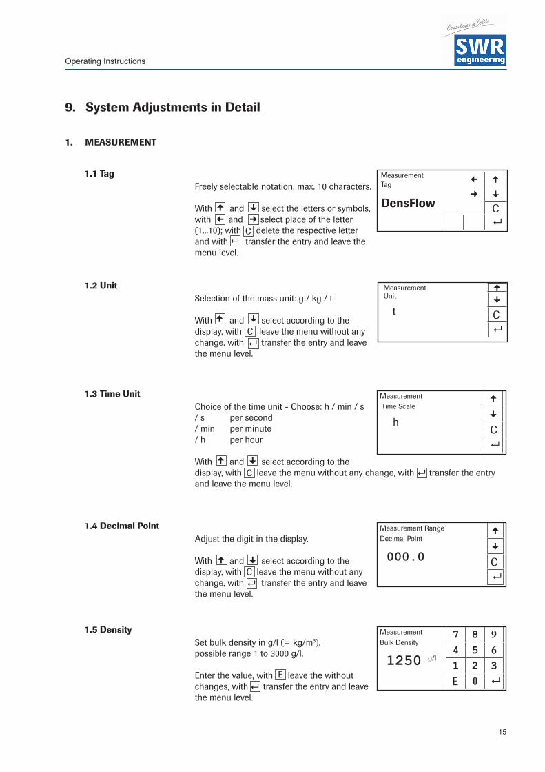
9. System Adjustments in Detail
1. MEASUREMENT
1.1 Tag Freely selectable notation, max. 10 characters.
With and select the letters or symbols, with and select place of the letter (1...10); with delete the respective letter and with transfer the entry and leave the menu level.
1.2 UnitSelection of the mass unit: g / kg / t
With and select according to the display, with leave the menu without any change, with transfer the entry and leave the menu level.
1.3 Time UnitChoice of the time unit - Choose: h / min / s/ s per second/ min per minute/ h per hour
With and select according to the display, with leave the menu without any change, with transfer the entry and leave the menu level.
1.4 Decimal PointAdjust the digit in the display.
With and select according to the display, with leave the menu without any change, with transfer the entry and leave the menu level.
1.5 DensitySet bulk density in g/l (= kg/m3), possible range 1 to 3000 g/l. Enter the value, with leave the without changes, with transfer the entry and leave the menu level.
£
Measurement ¡ £Tag
¢ ¤DensFlow C
8
¤¢
8C
Measurement £Unit ¤ t C
8£
C8
C8
Measurement £ Time Scale
¤h
C8
Measurement Range £Decimal Point
¤000.0 C
8
¤
£ ¤
¡
£C 8¤
E8
Measurement 7 8 9Bulk Density
4 5 61250 g/l
1 2 3 E 0 8
Operating Instructions
16
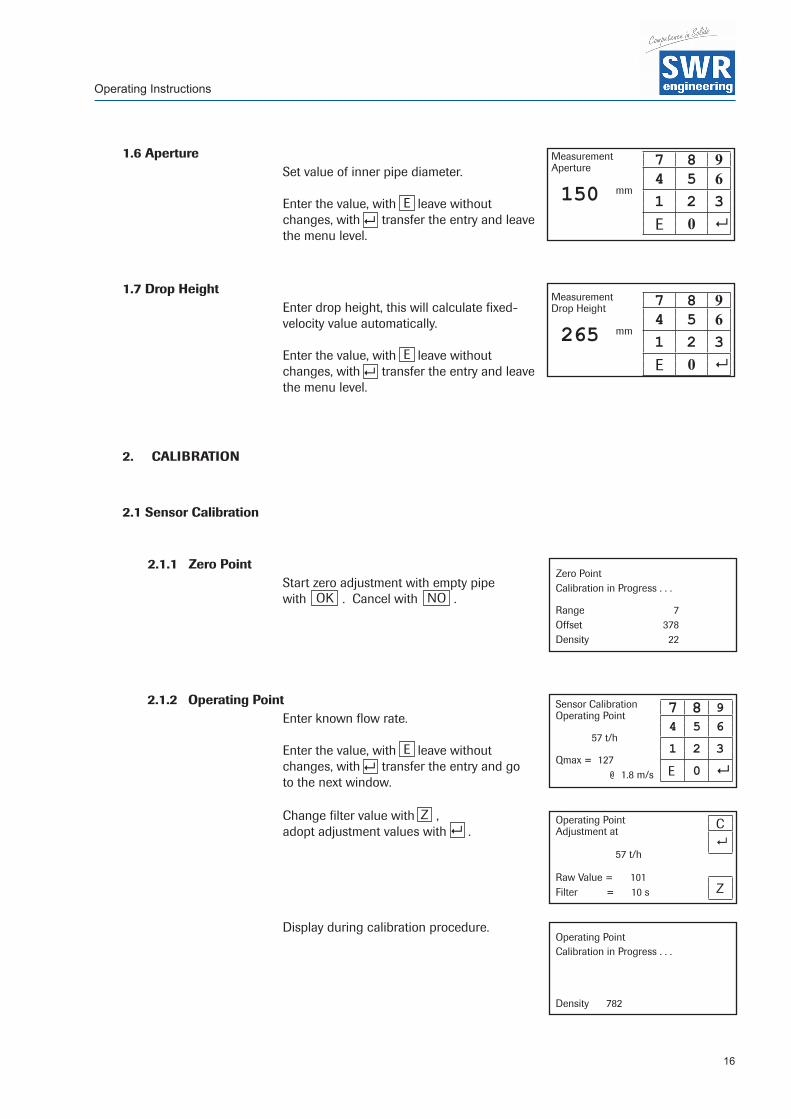
1.6 ApertureSet value of inner pipe diameter. Enter the value, with leave without changes, with transfer the entry and leave the menu level.
1.7 Drop HeightEnter drop height, this will calculate fixed- velocity value automatically. Enter the value, with leave without changes, with transfer the entry and leave the menu level.
2. CALIBRATION
2.1 Sensor Calibration
2.1.1 Zero PointStart zero adjustment with empty pipe with . Cancel with .
2.1.2 Operating PointEnter known flow rate. Enter the value, with leave without changes, with transfer the entry and go to the next window.
Change filter value with , adopt adjustment values with .
Display during calibration procedure.
E8
E8
Measurement 7 8 9Aperture
4 5 6150 mm
1 2 3E 0 8
OK
Zero PointCalibration in Progress . . .
Range 7Offset 378Density 22
E8
Sensor Calibration 7 8 9Operating Point
4 5 657 t/h
1 2 3Qmax = 127
E 0 8@ 1.8 m/s
Measurement 7 8 9Drop Height
4 5 6265 mm
1 2 3E 0 8
NO
Operating Point CAdjustment at
857 t/h
Raw Value = 101ZFilter = 10 s
Operating PointCalibration in Progress . . .
Density 782
Z8

Operating Instructions
17
2.1.3 Full CalibrationCalibration with 100 % filled pipe in no-flow condition.
Set full calibration with . Cancel with .
2.2 Factor Correction factor affects directly the density measurement. 0.01 to 9.99 Default 1.0 Enter the value, with leave without changes, with transfer the entry and leave the menu level.
2.3 Interpolation PointsSet amount of required interpolation points; maximum 3 points are possible. Enter the value, with leave without changes, with transfer the entry and leave the menu level.
2.4 Interpolation Table
Display of the calibrated points. Back with .
2.5 Min. LoadSuppresses conveying breaks during Auto Acquisition. Enter the value, with leave without changes, with transfer the entry and leave the menu level.
2.6 Interpolation Point 1
2.6.1 Raw ValueManual interpolation. This is the non-linearized flow value.
Enter the value, with leave without changes, with transfer the entry and leave the menu level.
Full PointCalibration in Progress . . .
Density 782
E
Interpolation Tableraw calibrated
1. 57 57 t/h2. 84 84 t/h
E
Calibration 7 8 9Min. Load
4 5 610 %
1 2 3
E 0 8
Calibration 7 8 9Factor
4 5 61.0 1 2 3
E 0 8
Interpolation 7 8 9Points
4 5 62 1 2 3
E 0 8
E8
E8
E
8
Interpolation Point 1 7 8 9Raw Value
4 5 657 t/h
1 2 3
E 0 8E
8
OKNO

Operating Instructions
18
2.6.2 CalibratedManual interpolation. Linearized flow value. Enter the value, with leave without changes, with transfer the entry and leave the menu level.
2.6.3 Auto AcquisitionEnables a calibration by means of a weighed mass. The collection of data starts with entering this menu point, but only flow rates above the min. load value will be counted. Finish with , enter the conveyed mass and confirm with . Press to leave menu point without any changes.
2.7. / 2.8 Interpolation point 2 / 3 same as point 1
3. OUTPUTS
3.1 Flow Rate
3.1.1 at 20 mAEnter end of measuring range, this will comply to 20 mA. Enter the value, with leave without changes, with transfer the entry and leave the menu level.
3.1.2 FilterAdjustable damping for the flow rate. Range: 0.1 . . . 99.9 s (Standard 1 s) Enter the value, with leave without changes, with transfer the entry and leave the menu level.
3.1.3 Calibration 4 mAAll current outputs are calibrated at the factory. If necessary recalibration with multimeter is possible.
With and adjust fast, with and adjust slowly the current to 4 mA. With transfer the entry and leave the menu level, with leave the menu without any change.
Auto AcquisitionButton [C] breakButton [ENTER] finishCollected Data: 276 probes
C 8
Charged 7 8 9Amount
4 5 657 t
1 2 3
E 0 8
Flow Rate 7 8 9Value at 20 mA
4 5 6100 t/h
1 2 3
E 0 8
Flow Rate 7 8 9Filter
4 5 61.0 s
1 2 3
E 0 8
Interpolation Point 1 7 8 9Calibrated
4 5 657 t/h
1 2 3
E 0 8E
8
88 E
E8
E8
Flow RateCalibration 4.0 mA
C<< < > >> 8
<<8
C
>> <>

Operating Instructions
19
3.1.4 Calibration 20 mAAll current outputs are calibrated at the factory. If necessary recalibration with multimeter is possible.
With and adjust fast, with and adjust slowly the current to 4 mA. With transfer the entry and leave the menu level, with leave the menu without any change.
3.2. Output 2
3.2.1 at 20 mAEnter end of measuring range, this will comply to 20 mA. Enter the value, with leave without changes, with transfer the entry and leave the menu level.
3.2.2 FilterAdjustable damping for the density. Range: 0.1 . . . 99.9 s (Standard 1 s) Enter the value, with leave without changes, with transfer the entry and leave the menu level.
3.2.3 Calibration 4 mAAll current outputs are calibrated at the factory. If necessary recalibration with multimeter is possible.
With and adjust fast, with and adjust slowly the current to 4 mA. With transfer the entry and leave the menu level, with leave the menu without any change.
3.2.4 Calibration 20 mAAll current outputs are calibrated at the factory. If necessary recalibration with multimeter is possible.
With and adjust fast, with and adjust slowly the current to 4 mA. With transfer the entry and leave the menu level, with leave the menu without any change.
Flow RateCalibration 20 mA
C< < > >> 8
DensityCalibration 20 mA
C<< < > >> 8
<<8
C
>> <>
Density 7 8 9Value at 20 mA
4 5 6500 g/l
1 2 3
E 0 8E
8
Density 7 8 9Filter
4 5 61.0 s
1 2 3
E 0 8E
8
DensityCalibration 4 mA
C<< < > >> 8
<<8
C
>> <>
<<8
C
>> <>

Operating Instructions
20
3.3 VELOCITY
3.2.1 at 20 mAEnter end of measuring range, this will comply to 20 mA. Enter the value, with leave without changes, with transfer the entry and leave the menu level.
3.2.2 FilterAdjustable damping for the velocity. Range: 0.1 . . . 99.9 s (Standard 1 s) Enter the value, with leave without changes, with transfer the entry and leave the menu level.
3.2.3 Calibration 4 mAAll current outputs are calibrated at the factory. If necessary recalibration with multimeter is possible.
With and adjust fast, with and adjust slowly the current to 4 mA. With transfer the entry and leave the menu level, with leave the menu without any change.
3.2.4 Calibration 20 mAAll current outputs are calibrated at the factory. If necessary recalibration with multimeter is possible.
With and adjust fast, with and adjust slowly the current to 4 mA. With transfer the entry and leave the menu level, with leave the menu without any change.
VelocityCalibration 20 mA
C<< < > >> 8
Velocity 7 8 9Value at 20 mA
4 5 610 m/s
1 2 3
E 0 8E
8
Velocity 7 8 9Filter
4 5 61.0 s
1 2 3
E 0 8E8
VelocityCalibration 4 mA
C<< < > >> 8
<<8 C>> < >
<<8
C
>> <>

Operating Instructions
21
3.4 ALARM
3.4.1 TypeUpper and lower limit value. Affects relays.
With and select according to your significance, with leave the menu without any change, with transfer the entry and switch to a deeper menu level.
3.4.2 Value of AlarmFlow value for the alarm.
With leave the menu without any change, with transfer the entry and leave the menu level.
3.4.3 DelayThreshold value how long the value must be over or under the limit until the alarm relay reacts. Range: 0.1 ... 99.9 s
With leave the menu without any change, with transfer the entry and leave the menu level.
3.4.4 HysteresisThreshold for resetting the alarm. Range: 0 ... 500 t/hWith leave the menu without any change, with transfer the entry and leave the menu level.
3.4.5 Output Alarm / calibration active Selection of signalisation mode using the relay either as “alarm signal” or “status signal” for auto calibration unit.
With and select according to the display, with leave the menu without any change, with transfer the entry and leave the menu level.
3.4.6 ModeChoice of the contact work or interruption. NO - Working current NC - Static current
With and select according to the display, with leave the menu without any change, with transfer the entry and leave the menu level.
Alarm £Alarm type
¤Maximum
C
8
C8
£ ¤
8E
Alarm 7 8 9Value of Alarm
4 5 690 t/h
1 2 3
E 0 8
Alarm 7 8 9Delay
4 5 61.0 s
1 2 3
E 0 8
8C
Alarm 7 8 9Hysteresis
4 5 685 t/h
1 2 3
E 0 88E
Alarm £Operation Mode
¤NO
C8
C8
£ ¤
Alarm £Output
¤Alarm
C8
C8
£ ¤

Operating Instructions
22
3.4.7 Sensor FaultOn / Off Affects to alarm relay. With and select according to the display, with leave the menu without any change, with transfer the entry and leave the menu level.
3.5 Pulse Output
The pulse output is potential free (optocoupler), wiring see page 24.
3.5.1 Amount of Pulses / Mass UnitType desired number of pulses per massunit. This should not exceed 50 Hz. Input with the count keyboard. With leave the menu without any change, with transfer the entry and leave the menu level.
4. DIGITAL INPUTS
The digital inputs are potential free (optocoupler), wiring see page 24.
4.1 Digital Input 1
4.1.1 FunctionDigital input for trigger signal to start zero or full calibration.Select input function. Not one / S-Zero / S-Full Possibility to start function with external signal. With and select according to the display, with leave the menu without any change, with transfer the entry and leave the menu level.
4.1.2 DirectionDirect / Inverted With and select according to the display, with leave the menu without any change, with transfer the entry and leave the menu level.
4.1.3 FilterIdle time after activation. (Anti beat device for mechanical switches.) With leave the menu without any change, with transfer the entry and leave the menu level.
4.2 Digital Input 2 Same as Digital Input 1
Digital Input 1 £Direction
¤direct
C
8
Alarm £Sensor Fault
¤on
C8
8E
Digital Input 1 £Function
¤S-Full
C
8
C8
£ ¤
8E
Pulse Output 7 8 9Mass / Pulse
4 5 610.00
1 2 3
E 0 8
C8
£ ¤
C8
£ ¤
Digital Input 1 7 8 9Filter
4 5 60.0 s
1 2 3
E 0 8

Operating Instructions
23
5. SYSTEM
5.1 Baud RateIndicating of the Baud Rate Choose: 4800 / 9600 / 19200 / 38400 With and select according to your significance, with leave the menu without any change, with transfer the entry and leave the menu level.
5.2 ModBus-AddressSet 1 . . . 250 With leave the menu without any change, with transfer the entry and leave the menu level.
5.3 ContrastDisplay contrast for a better legibility. With and adjust fast, with and adjust slowly to the contrast required. With transfer the entry and leave the menu level, with leave the menu without any change.
5.4 Language
Select of the Language. Choose: D / F / E With and select according to your significance, with leave the menu without any change, with transfer the entry and leave the menu level.
C8
£ ¤
System £Baud Rate
¤9600
C8
8E
System 7 8 9Address
4 5 61 1 2 3
C 0 8
<<
8C
>> <>
System Contrast
C<< < > >> 8
C8
£ ¤
System £Language
¤ D
C8

Operating Instructions
24
10. Connection Examples
10.1 Digital Input
▼
UST
10.2 Impulse Output
R = (Ub - 0.7 V)/l
RV = ((UST - 1.6 V) / 20 mA) - 2 kW
Open: 0 VClosed: Ub - 0.7 V
Open: UbClosed: 0.7 V
Open Collector
Open Collector

Operating Instructions
25
• Warning! Danger of shock with open housing!
• Switch off the supply voltage for all maintenance or repair works on the measuring system. The pipe must not be in operation during a sensor exchange.
• Repair and maintenance work must be carried out by trained or expert personnel only.
• Before hot-work the sensor must be removed from the piping.
11. WarrantyWarranty is granted for one year starting from delivery date under the condition that the operating instructions have been followed, no interventions on the appliances have been made and the components of the system show no mechanical damage or wear resistance. In case of a defect during the warranty period, defective components are repaired or are replaced free of charge. Replaced parts turn into the property of SWR. If desired by the costumer that the parts should be repaired or replaced in its factory, then the costumer has to take over the costs for the SWR-service staff. SWR is not responsible for damage, which did not develop at the delivery article; especially SWR is not responsible for escaped profit or other financial damages of the customer.
12. Trouble Shooting
• Warning! The electrical installation must only be checked by expert personnel.
Problem Cause Measure
Measuring system does not work.
Power supply interrupted.
Break of cable.
Device defective.
Check the power supply.
Check the connection cables for a possible break of a cable.
Please call SWR for further instructions.
Measuring system outputs wrong values.
Calibration not correct.
Calibration changed by abrasion on front end of sensor
Correction factor place on 1, new calibration according to section 6.
Correction factor place on 1, new calibration according to section 6.
Sensor error Wrong connection of the sensor.
Sensor out of order.
Check the wiring.
Exchange sensor.
Do not open, as otherwise the warranty claim expires!

Operating Instructions
26
13. Technical Data
SensorHousing Stainless Steel 1.4571
NW 10 ... 125, flange DIN 2576Inner pipe Ceramic (AI2O3)
Protection category IP 65 according EN 60 529/10.91Environment temperature Sensor pipe: -20 ... + 120 °C
Sensor electronic: 0 ... + 60 °CMax. working pressure 16 bar
Working frequency 88 kHz
Transmitting power Max. 2 mW
Weight Depending to model
Dimensions NW + 150 mm, L 500 mm
Accuracy +/- 2 ... 5 % in calibrated measuring range
Transmitter (version field housing)
Power supply 110 / 240 V AC 50 Hz (optional 24 V DC)
Power consumption 12.5 W
Protection category IP 65 according EN 60 529/10.91
Dimensions 225 x 237 x 174 (W x H x D)
Weight Ca. 2.5 kg
Terminal clamp wire size 0.2 - 2.5 mm2 [AWG 24-14]
Cable Glands 3 x M16 (4.5 - 10 mm Ø)Alarm outputError output
Relay with toggle switch - max. 250 V AC, 1 ARelay NC - max. 250 V AC, 1 A
Transmitter (version 19” rack system)
Power supply 24 V DC
Power consumption 12.5 W
Protection category IP 30 according EN 60 529/10.91
Dimensions 19” rack system, 3HE, 28TE, L = 227 mm
Weight ca. 1 kg
Connection Connector (DIN 41612), Typ B, 32-pol., connector
Alarm output Relay NC - max. 250 V AC, 1 A
Additional Data
Environment temperature -10 ... +45 °C
Current outputs 3 x 4 ... 20 mA (0 ... 20 mA), load < 500 W
Digital inputs 2 x Ri 2 kW, 5 - 50 mA
Data storage Flash Memory
Impulse output Open Collector - Max. 30 V, 20 mA
USB interface 2.0
RS 485 interface ModBus-Protocol
EN 20/04/2012
SWR engineering Messtechnik GmbHGutedelstraße 31 · 79418 Schliengen (Germany)Fon +49 7635 82 72 48-0 · Fax +49 7635 82 72 48-48 · www.swr-engineering.com (A
ll rig
hts
rese
rved
.)