flow and transport properties of salt rocks · chapter 5.2 flow and transport properties of salt...
TRANSCRIPT

Chapter 5.2
Flow and Transport Properties of Salt Rocks
5
J.L. Urai · Z. Schléder · C.J.Spiers · P.A. Kukla
5.2.1 IntroductionDuctile evaporites play a key role in controlling the dy-namical evolution of many sedimentary basins. We re-view the mechanical and transport properties of these rocks focusing on halite, bischofite and carnallite. Reli-able modelling of salt flow during basin evolution, or of salt flow related to long-term engineering challenges, requires extrapolation of experimentally-derived flow laws to strain rates much lower than those attainable in the laboratory. This extrapolation must be based on an understanding of the microscale deformation mecha-nisms operating under these conditions, obtained by combining studies of natural laboratories with experi-mental work. The engineering creep laws generally
used in the salt mining industry are based on dislocation creep processes quantified in laboratory experiments of necessarily limited duration. However, a large body of evidence clearly demonstrates that under conditions of long-term deformation, grain boundary dissolution-pre-cipitation processes, such as solution-precipitation creep (or “pressure solution”) and dynamic recrystallisation, play a significant role. The operation of these processes can cause major changes in rheology. Moreover, the high fluid pressures associated with deforming evapo-rite systems can lead to dramatic increases in permeabil-ity, strongly reducing sealing capacity. These properties must be incorporated in quantitative models of evaporite basins to obtain realistic descriptions of salt behavior at the necessary range of length and time scales.
Table 5.2.1 List of the main evaporite minerals and the wireline log properties of evaporite rocks formed by these.
Name Formula Density GRNeutron
“Porosity”
Sonic transit time
kgm-3 API % msft-1
Bischofite MgCl2 . 6 H
2O 1560 0 > 60 100
Carnallite KMgCl3 . 6 H
2O 1570 220 65 78
Epsomite MgSO4 . 7 H
2O 1710 0 > 60
Sylvite KCl 1860 500 -3 74
Halite NaCl 2040 0 -3 67
Kainite MgSO4KCl . 3 H
2O 2120 245 45
Gypsum CaSO4 . 2 H
2O 2350 0 >60 52
Kieserite MgSO4 · (H
2O) 2590 0 38
Calcite CaCO3
2710 0 -1 49
Polyhalite K2Ca
2Mg(SO
4)
4·2 (H
2O) 2790 180 15 57
Langbeinite K2Mg
2(SO
4)
32820 275 0 52
Dolomite CaCO3 MgCO
32870 0 1 44
Anhydrite CaSO4
2980 0 -2 50

5.2.2 Physical properties of evaporites
Most evaporite rock sequences consist mainly of carbon-ates, sulphates and chlorides, Halite rock is generally the dominant chloride lithology and due to its low creep strength, low static porosity, permeability and low density it exerts a profound influence on basin evolution - through salt tectonic movement and fluid trapping. Other chloride evaporite rocks, though volumetrically much less impor-tant than halite, carbonate or sulphate lithologies, can also have important effects because of their exceptionally weak rheology (causing heterogeneous deformation and drilling problems) or chemical composition (salt metamorphism and fluid flow). In table 5.2.1 the main evaporite minerals are listed together with their wireline log properties.
5.2.3 Deformation mechanisms and rheology of halite in experiments 5.2.3.1 Deformation mechanisms and associated processes
Polycrystalline halite rocks (rock salt) consist of grains of halite (NaCl), with a diameter between 0.01 mm and
several dm, containing impurities in solid solution, sec-ondary mineral phases and fluids trapped in inclusions, grain boundaries or in pores. The mean grain size of most halite rocks lies in the range 2-20 mm, though extrusive salts may show much finer mean values (0.5 mm) while secondary salt can be much coarser (10-30 cm).
Under deviatoric stress, rock salt can deform by a range of processes. The deformation mechanisms known to op-erate at temperatures relevant for engineering and natu-ral halokinetic conditions (20-200 °C) are summarised in figure 5.2.1. At very low effective confining pressures (less than a few MPa) and high deviatoric stresses (> 15-20 MPa), inter- and intragranular microcracking, grain rotation and intergranular slip are important strain accu-mulating processes alongside crystal plasticity, and the mechanical properties and dilatational behaviour are de-pendent on the effective mean stress or effective confining pressure (Cristescu and Hunsche 1998; Peach and Spiers 1996; Cristescu 1998; Peach et al. 2001). At sufficiently high deviatoric stress, the material fails in a (semi)brittle manner, with failure described by a pressure (effective mean stress) dependent failure envelope. With increasing effective mean stress, microcracking and dilatancy are suppressed and crystal plastic processes dominate.
At temperatures in the range 100-200 °C, dislocation creep is important in laboratory experiments, and poly-crystalline halite can deform to large strains by this mech-
Figure 5.2.1. Schematic drawing of the micro-structural processes that can oper-ate during deformation of rock salt at temperatures in the range 20-200 °C. Different shades of green represent crystals with different orientation. See text for explana-tion
278 J.L. Urai · Z. Schléder · C.J. Spiers · P.A. Kukla
anism (Fig. 5.2.2), even at confining pressures as low as 10 MPa. During this process, subgrains are formed in the halite grains (Pennock et al. 2005, 2006a,b), with the diam-eter of the subgrains showing an near-linear, inverse cor-relation with deviatoric stress (Carter et al. 1993, see Fig. 5.2.11). If the polycrystal contains small but significant amounts of water in the form of saturated brine inclusions or grain boundary films, as is generally the case for both natural and synthetic samples, fluid assisted grain boundary migration generally operates. This is an efficient process of reducing dislocation density and hence removing the stored energy of dislocations, even at room temperature (Schenk and Urai 2004; Schenk et al. 2006, see Fig. 5.2.3).
While dislocation creep processes take place in the crystal lattice of the halite grains, and fluid assisted grain boundary migration involves solution-precipitation trans-
fer across grain boundaries, solution-precipitation creep, or “pressure solution”, is a process which involves mass transfer around grain boundaries. Here, in the presence of a small amount of saturated grain boundary brine, grains dissolve at highly stressed boundaries, and after diffu-sion of the material through the grain boundary fluid, the material crystallises at interfaces under low normal stress (Schutjens and Spiers 1999; Spiers et al. 2004; Fig. 5.2.4). This process is accompanied by intergranular sliding and rotation (grain rearrangement), and can lead to compac-tion of porous salt or to deviatoric strain of non-porous aggregates (Spiers et al. 1990).
Solution - precipitation creep is an important deforma-tion mechanism in most wet rock systems in the Earth’s crust (Renard and Dysthe 2003), but is especially rapid in rock salt. Early reports, theoretical treatments and
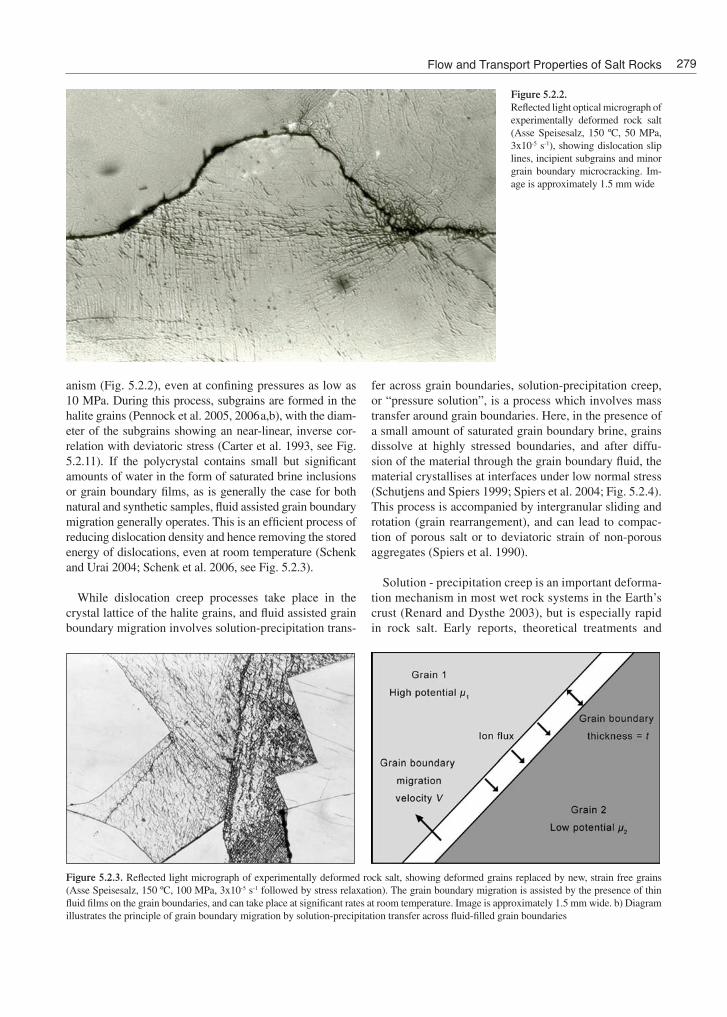
Figure 5.2.2. Reflected light optical micrograph of experimentally deformed rock salt (Asse Speisesalz, 150 ºC, 50 MPa, 3x10⁻⁵ s-1), showing dislocation slip lines, incipient subgrains and minor grain boundary microcracking. Im-age is approximately 1.5 mm wide
Figure 5.2.3. Reflected light micrograph of experimentally deformed rock salt, showing deformed grains replaced by new, strain free grains (Asse Speisesalz, 150 ºC, 100 MPa, 3x10⁻⁵ s-1 followed by stress relaxation). The grain boundary migration is assisted by the presence of thin fluid films on the grain boundaries, and can take place at significant rates at room temperature. Image is approximately 1.5 mm wide. b) Diagram illustrates the principle of grain boundary migration by solution-precipitation transfer across fluid-filled grain boundaries
Flow and Transport Properties of Salt Rocks 279
reviews of solution-precipitation creep in rocks are given by Durney (1976), Rutter (1976), Sprunt and Nur (1977), Rutter (1983) and Tada and Siever (1996). Recent theoretical treatments of the process are given by Lehner (1990) and Kruzhanov and Stöckhert (1998). In brief, the differences in chemical potential μ between points in the
solid at grain boundaries under high stress and those un-der lower stress provide the driving force for dissolution, transport by diffusion in the intergranular fluid, and pre-cipitation (Fig. 5.2.3). Additional driving force (chemical potential drop) both along and across grain boundaries can be provided by internal plastic deformation of the
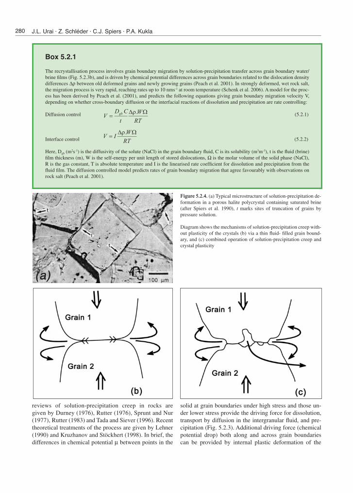
Box 5.2.1
The recrystallisation process involves grain boundary migration by solution-precipitation transfer across grain boundary water/brine films (Fig. 5.2.3b), and is driven by chemical potential differences across grain boundaries related to the dislocation density differences Δρ between old deformed grains and newly growing grains (Peach et al. 2001). In strongly deformed, wet rock salt, the migration process is very rapid, reaching rates up to 10 nms-1 at room temperature (Schenk et al. 2006). A model for the proc-ess has been derived by Peach et al. (2001), and predicts the following equations giving grain boundary migration velocity V, depending on whether cross-boundary diffusion or the interfacial reactions of dissolution and precipitation are rate controlling:
Diffusion control (5.2.1)
Interface control (5.2.2)
Here, Dgb (m2s-1) is the diffusivity of the solute (NaCl) in the grain boundary fluid, C is its solubility (m3m-3), t is the fluid (brine) film thickness (m), W is the self-energy per unit length of stored dislocations, Ω is the molar volume of the solid phase (NaCl), R is the gas constant, T is absolute temperature and I is the linearised rate coefficient for dissolution and precipitation from the fluid film. The diffusion controlled model predicts rates of grain boundary migration that agree favourably with observations on rock salt (Peach et al. 2001).
Figure 5.2.4. (a) Typical microstructure of solution-precipitation de-formation in a porous halite polycrystal containing saturated brine (after Spiers et al. 1990), t marks sites of truncation of grains by pressure solution.
Diagram shows the mechanisms of solution-precipitation creep with-out plasticity of the crystals (b) via a thin fluid- filled grain bound-ary, and (c) combined operation of solution-precipitation creep and crystal plasticity
280 J.L. Urai · Z. Schléder · C.J. Spiers · P.A. Kukla
grains, giving rise to combined grain boundary migration and solution-precipitation creep.
The above processes have been documented in laborato-ry experiments and in naturally deformed salt from a wide range of settings (Urai et al. 1987; Trimby et al. 2000; Ter Heege et al. 2005a,b; Schléder and Urai 2007; Schléder et al. 2007). The relative importance of each process depends strongly on variables such as temperature, con-fining pressure, grain size, solid solution impurities and second phase content, and, importantly, on the presence of sufficient water in grain boundaries to enable solution-precipitation phenomena (Fig. 5.2.5). Fluid assisted grain boundary migration and solution-precipitation processes do not operate in dry salt, i.e., synthetic samples made of carefully dried material (< 5 ppm water, Ter Heege et al. 2005a,b) or natural samples deformed under dilatant conditions which allow intergranular water to evaporate (Peach et al. 2001). The fields in which different defor-mation mechanisms are dominant can be represented in deformation mechanism maps (Ter Heege et al. 2005a,b). Note that published deformation mechanism maps tend to differ in the mechanisms included, depending of the time scales of interest and on whether the effects of water (brine) are included or not.
5.2.3.2 Rheological behaviour – “flow laws”
The rheology of a given crystalline material depends on the dominant deformation mechanism, which in turn depends on the time scale and hence deformation
rate of interest. For rock salt, summaries of behaviour observed in experiments have been published by, for example, Urai et al. (1986b), Cristescu and Hunsche (1998), Hunsche and Hampel (1999) and Ter Heege et al. (2005a,b).
Solution- precipitation creep has been widely recorded in laboratory experiments on wet, fine grained (< 500 μm) polycrystalline halite at temperatures in the range 20-200 °C, leading to quite rapid linear viscous deformation of dense salt (Eq. 5.2.2) and compaction of porous mate-rial (e.g., Urai et al. 1986; Spiers et al. 1990; Renard et al. 2004; Ter Heege et al. 2005b). The process has also been observed at individual halite grain contacts under stress (e.g., Gratier 1993; Schutjens and Spiers 1999; De Meer et al. 2005) and in salt aggregates containing second phases (Renard et al. 2001; Zoubtsov et al. 2004). Possible evidence for pressure solution has also been reported by Berest et al. (2005) in low stress creep experiments on coarse, natural rock salt, in which much faster rates of deformation were observed than expected by extrapolat-ing conventional dislocation creep laws obtained at higher stresses and strain rates (cf. Fig. 5.2.5). In addition, rapid long-term deformation of pillars and galleries in potash mines has been attributed to solution-precipitation creep in rock salt (Campos de Orellana 1998; Lee and de Souza 1998), though such in-situ experiments have not yet been sufficiently documented to allow full quantification of the processes operating (Bekendam and Urai 2007).
However, because of the strong grain size dependence and limited duration of laboratory tests, solution-precipi-tation creep is rarely seen in experiments on natural rock
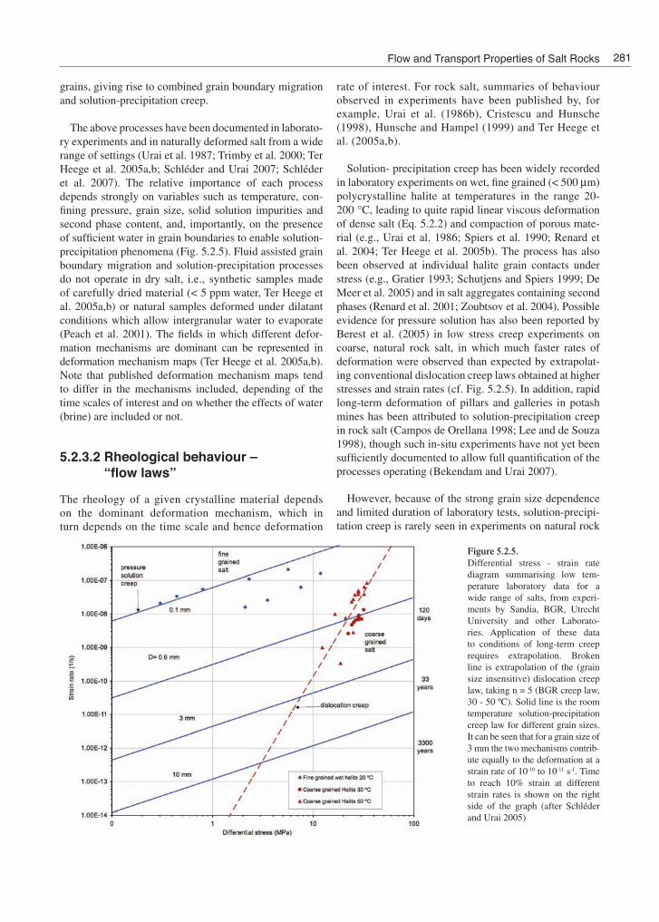
Figure 5.2.5. Differential stress - strain rate diagram summarising low tem-perature laboratory data for a wide range of salts, from experi-ments by Sandia, BGR, Utrecht University and other Laborato-ries. Application of these data to conditions of long-term creep requires extrapolation. Broken line is extrapolation of the (grain size insensitive) dislocation creep law, taking n = 5 (BGR creep law, 30 - 50 ºC). Solid line is the room temperature solution-precipitation creep law for different grain sizes. It can be seen that for a grain size of 3 mm the two mechanisms contrib-ute equally to the deformation at a strain rate of 10-10 to 10-11 s-1. Time to reach 10% strain at different strain rates is shown on the right side of the graph (after Schléder and Urai 2005)
Flow and Transport Properties of Salt Rocks 281

salt (grain size typically 1 cm), and it is therefore not usu-ally included in engineering descriptions of salt rheology (Cristescu and Hunsche 1998; Hunsche and Hampel 1999). Nonetheless, predictions made using equation 5.2.4 suggest that provided the salt contains sufficient water (>10-20 ppm, as most natural salts do), pressure solu-tion creep should become important at strain rates below those reached in experiments (see Fig. 5.2.5 and 5.2.6).
As indicated above, at low confining pressures and high deviatoric stresses, flow of rocksalt is accompanied by
dilatant grain boundary microcracking and rapid perme-ability increase (Cristescu and Hunsche 1998; Peach and Spiers 1996). The mechanical conditions under which this occurs have been accurately delineated by Cristescu and Hunsche (1998) and Cristescu (1998). While the on-set of microcracking has a minor direct effect on creep behaviour, it is important to note that it can strongly in-fluence the effects of water on creep. In salt containing small quantities of water, microcracking disrupts grain boundary films and inhibits both grain boundary migra-tion and pressure solution, particularly if the water can
Box 5.2.2
Considering steady state, non-dilatant deformation, the main classes of equations for the creep strain rate of rock salt are written
for dislocation creep, and
for solution- precipitation creep, with the total strain rate being the sum of the two
In these equations, written in a form appropriate for axially symmetric compressive deformation, A and B are material parameters, QDC and QPS represent (apparent) activation energies for dislocation and pressure solution creep, R is the gas constant, T is absolute temperature, σ1 andσ3 are the maximum and minimum principle compressive stresses, D is grain size, and n and m are the exponents of stress and grain size respectively. Two important differences between equations 5.2.1 and 5.2.2 are firstly the dependence of strain rate on stress (n = 1 for solution-precipitation creep or pressure solution while n > 1 for disloca-tion creep – see figure 5.2.5 and 5.2.6), and secondly the dependence of strain rate on grain size. Note that for dislocation creep deformation is grain size independent, while the exponent m = 3 makes pressure solution creep strongly grain size dependent (Fig. 5.2.5 and 5.2.7).
At 20-200 °C, differential stresses below 15-20 MPa and strain rates below 10-6 s-1, both uniaxial and triaxial experiments on natural and synthetic rock salt show power law dislocation creep behaviour (Eq. 5.2.3) with a stress exponent n of 5-6 at the higher stresses and 3.5-4.5 at lower stresses (Wawersik and Zeuch 1986; Carter et al. 1993; Hunsche and Hampel 1999). The apparent activation energy for creep is unusually low, taking values of 50-80 kJmol-1. Intragranular microstructural signatures including wavy deformation band (slip/sub-boundary) structures suggest that cross-slip of screw dislocations may be the rate controlling process at differential stresses (σ1
-σ3) above 10-15 MPa (n = 5-6), while well formed equiaxed subgrains indicate that climb-controlled recovery becomes dominant at lower stresses (n = 3-4)solid solution, amount and distribution of secondary mineral phases, grainsize, subgrain size, dislocation density and fluids in grain boundaries.
Deformation experiments, performed in the dislocation creep field at confining pressures high enough to suppress dilatancy (> 10-20 MPa), have shown that “wet” samples containing more than 10-20 ppm of water (brine) at grain boundaries undergo rapid dynamic recrystallisation by fluid assisted grain boundary migration, alongside dislocation creep. Compared with dry rocksalt samples (<10 ppm water), this recrystallisation process leads to a reduction in average dislocation density, an associated reduction of flow strength by 25-50% and power law flow behaviour with an n-value of about 4.5 (Peach et al. 2001; Ter Heege et al. 2005b). In addition, during dynamic recrystallisation of wet salt (>10-20 ppm), the grain size evolves such that a systematic relation between grain size, flow stress and temperature is established, with deformation occurring close to the boundary between the dislocation and solution-precipitation or pressure solution creep fields (Ter Heege et al. 2005a; Fig. 5.2.8). The equation relat-ing mean recrystallised grain size (DDRX measured in μm) to differential stress (MPa) and temperature obtained by Ter Heege et al. (2005a) shows only weak temperature dependence and can be viewed as a basis for estimating flow stresses from the dynami-cally recrystallized grain size of natural salt (i.e., as a so-called palaeopiezometer). The relation is given by
where b is the mean Burgers vector for halite (b=3.99 x 10⁻⁴ μm), G is its shear modulus (G=1.5 x 10⁴ MPa), log(K) = -1.55±0.24, p = 1.85 ± 0.23 and the (apparent) activation energy term QDRX/a = 14.2±2.8 kJmol-1.
(5.2.3)
(5.2.4)
(5.2.5)
(5.2.6)
282 J.L. Urai · Z. Schléder · C.J. Spiers · P.A. Kukla
escape from the sample (Peach et al. 2001). On the other hand, under conditions where microcracking allows free brine or water vapor access to the interior of a creeping salt sample, then both recrystallisation and solution-pre-cipitation creep effects can be strongly enhanced.
Note that despite the large amount of data now avail-able on solution-precipitation creep in salt, details of the
microphysics of the process are incompletely understood. This is at least partly due to the difficulties of imaging the fine-scale (1-200 nm) structure of wetted grain bounda-ries during deformation. Approaches applied here include in-situ optical, infrared and electrical resistivity mea-surements, interference microscopy and electron micro-scopy of frozen boundaries using cryo-SEM (Hickman and Evans 1995; Schutjens and Spiers 1999; Spiers et al.
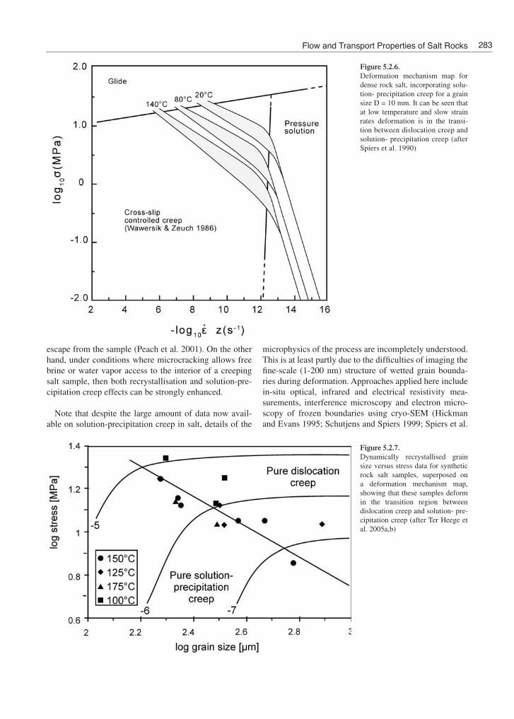
Figure 5.2.6. Deformation mechanism map for dense rock salt, incorporating solu-tion- precipitation creep for a grain size D = 10 mm. It can be seen that at low temperature and slow strain rates deformation is in the transi-tion between dislocation creep and solution- precipitation creep (after Spiers et al. 1990)
Figure 5.2.7. Dynamically recrystallised grain size versus stress data for synthetic rock salt samples, superposed on a deformation mechanism map, showing that these samples deform in the transition region between dislocation creep and solution- pre-cipitation creep (after Ter Heege et al. 2005a,b)
Flow and Transport Properties of Salt Rocks 283

2004; De Meer et al. 2002, 2005; Schenk et al. 2006). In-situ methods applied during active pressure solution in salt indicate that the grain boundary fluid is contained in a non-equilibrium or dynamically wetted island-channel structure, whose thickness varies with the crystallographic orientation and charge of the bounding crystal surfaces (e.g., De Meer et al. 2005). At sufficiently low intergranular effective stresses, however, surface energy driving forces are expected to become large enough, compared to stress-related driving forces, to cause healing of grain boundaries by island or contact growth, forming isolated fluid inclu-sions in the boundary (Schutjens and Spiers 1999). A basis to evaluate the conditions under which this will occur has recently been investigated by Van Noort et al. (2007) but is as yet difficult to apply in practice to a material such as halite. Further work is still needed in this area.
5.2.4 Deformation mechanisms and rheology of carnallite and bischofite
Much less is known about the rheology and deformation mechanisms of other evaporites. Carnallite and bischofite, which can both form layers up to 30 m thick, were inves-
tigated by Urai (1983), van Eekelen et al. (1984), Urai and Boland (1985), Urai (1985), Urai et al. (1986a), Urai (1987a,b) and Schenk and Urai (2005). It was shown that there are many similarities with halite, and dislocation creep, dynamic recrystallisation and solution-precipita-tion processes (Fig. 5.2.9) have been shown to occur both in laboratory samples and in naturally deformed samples. In addition, deformation twinning was shown to occur in both materials. Mechanical data (Fig. 5.2.10) point to a much weaker rheology than halite, while bischofite is much weaker than carnallite.
The rheology of anhydrite under conditions of natural deformation is virtually unknown. Existing studies are all done at high temperature and in dry samples, e.g., Dell‘Angelo and Olgaard (1995), and it is not clear how these can be extrapolated to natural conditions.
5.2.5 Natural laboratories
Studies of rock salt deformation in nature are essential for reliable extrapolation of laboratory data to describe the flow of salt during slow, human-induced or natural flow, because such studies provide a detailed understanding of the deformation mechanisms and microstructural processes
Figure 5.2.8. Steady state strain rate data of fine-grained wet rock salt samples de-forming by solution- precipitation processes, showing a stress expo-nent n close to 1. Gray bands repre-sent the theoretical flow law for this process (Eq. 5.2.4). (after Spiers et al. 1990)
284 J.L. Urai · Z. Schléder · C.J. Spiers · P.A. Kukla

that operate at strain rates well below those accessible in laboratory experiments. In recent years, major advances in this field have been reported, based on developments in microstructural and textural/orientation analysis using electron backscatter diffraction (EBSD), microstructure decoration by gamma-irradiation, Cryo-SEM and other methods. Samples from a wide range subsurface and sur-face locations have been studied (e.g., Schléder and Urai 2005, 2007; Schléder et al. 2007).
In addition there has recently been much progress in measuring the surface displacement field in areas of ac-tive salt tectonics, in salt mining districts, on sediment rafts above mobile salt, on emerging salt diapirs, and in areas where removal of ice sheets has led to a change of overburden load. These data can be inverted using non-linear finite element techniques, to obtain constitutive equations for salt flow during slow natural deformation (Weinberger et al. 2006; unpublished data). Insight into the in-situ rheology of salt on the time scale of years has also been gained by simply adjusting the flow laws used in numerical models of mining-related subsidence to ob-tain a match with surface displacement evolution. Studies of this type, conducted in relation to deep solution min-ing operations at Barradeel in the Netherlands (2-3 km depth), suggest salt flow behaviour involving dislocation creep (n value of 3-4) combined with a linear viscous flow law comparable to that expected for solution-precipitation creep.
Microstructural studies of naturally deformed salt show that low temperature dislocation glide and dislocation creep processes, solution-precipitation creep and water-assisted dynamic recrystallisation are all of major impor-tance (Urai et al. 1987; Schléder and Urai 2005, 2007). The relative importance of these processes varies strong-
ly, as a function of grain size, impurity content, stress path and fluid chemistry. Differential stress, as measured us-ing laboratory-calibrated subgrain-size piezometry (Fig. 5.2.11), is usually less than 2 MPa in rock salt deforming in nature, in agreement with in-situ stress measurements and geologic flow rates (Schléder and Urai 2005). Higher stresses, up to 5 MPa are recorded in the near-surface parts of diapir stems where salt is extruded to the surface (Schléder and Urai 2007).
Microstructural studies of subgrains and recrystallised grains in naturally deformed rocksalt also show, in agree-ment with recent experiments, that during fluid-assisted dynamic recrystallisation of salt in nature (water content >10 ppm), the grain size adjusts itself so that the material deforms close to the boundary between the dislocation and pressure solution creep fields. Power law flow, as meas-ured in recrystallising samples (Ter Heege et al. 2005a,b), with an n-value of about 4.5 is therefore proposed to be a good representation of this behavior. In samples which are sufficiently fine grained, solution-precipitation creep (Eq. 5.2.2), is found to be dominant both in salt glaciers recrystallised after extrusion to the surface, and in very fine grained primary rock salt in the subsurface (Schléder and Urai 2005, 2007). At geologic strain rates, such salt will be orders of magnitude weaker than would be predicted from extrapolation of short-term experiments on coarse-grained rock salt (see Fig. 5.2.5).
The rather high variability of flow strength in layers of rocksalt in nature is in good agreement with the small-scale folding ubiquitously observed in layers of naturally deformed salt. This has not yet been incorporated in nu-merical models of salt tectonics, which typically assume much more homogeneous material properties and accord-ingly produce much less heterogeneous strain fields.
Figure 5.2.9. Mechanical twinning, subgrain ro-tation and grain boundary migra-tion in experimentally deformed Asse carnallitite. Width of image is 4 mm
Flow and Transport Properties of Salt Rocks 285

It is an interesting and as yet unexplained microstructural observation that despite the high rate of fluid-assisted grain boundary migration observed in experiments, most natural-ly deformed rock salt is not completely recrystallised and preserves subgrains. A possible explanation for this is that below some critical difference in driving force for cross-boundary solution-precipitation transfer, surface energy driving forces cause necking or healing of grain boundary
fluid films to form isolated fluid inclusions (or possibly some other structural change), thus rendering the bounda-ries immobile in a manner analogous to that proposed above for cessation of pressure solution at low stresses.
In the following, we consider a number of recent ex-amples of how microstructural studies of natural salt can elucidate operative deformation processes and rheology in nature.
5.2.5.1 Evidence for diffuse dilatancy and fluid flow in rock salt in the deep subsurface
Intact rock salt has an extremely low permeability (< 10-21 m2), which imparts excellent sealing capacity. However, we know from experiments that at sufficiently low effective mean stress, dilatancy and extensional (Mode I) fracture can occur in deforming salt, producing significant perme-ability (Peach and Spiers 1996). If this occurs in nature, fluid flow will be possible. Evidence for fluid flow, in the form of saturated brines of different chemical composi-tion, and of hydrocarbons is frequently found in naturally deformed salt (Schléder et al. 2007; Schoenherr et al. 2007b; Magri et al. this volume). Microstructural evidence suggests that both diffuse dilatancy and Mode I fracturing can occur at very low effective stress conditions, i.e., at near-lithostatic fluid pressures and differential stress of a few MPa, in the deep subsurface, followed by crack heal-ing through precipitation form supersaturated solutions.
Figure 5.2.10. Summary diagram of the mechanical properties of bischofite and carnallite, compared with rock salt. It can be seen that carnallite is much weaker than halite, and bischofite in turn is much weaker than carnallite
Figure 5.2.11. Subgrain-size versus differential stress data from experimentally deformed rock salt, providing the basis for measurement of in-situ differential stress in core samples. Solid dots with error bars are the application of this technique to Hengelo rock salt (after Schléder and Urai 2005)
286 J.L. Urai · Z. Schléder · C.J. Spiers · P.A. Kukla

5.2.5.2 Fluid Flow in Fractures: A case study of the Neuhof Mine Germany
Zechstein (Z1) rocksalt core samples from the immediate vicinity of the Hessen potash bed from the Fulda basin were studied by Schléder et al. (2007). Here the anhydrite and halite are folded into tight, isoclinal folds and (the sequence) is cut by an undeformed, 1 cm thick, coarse-grained halite vein (Fig. 5.2.12). Microstructures were in-vestigated in etched, gamma-irradiated thin sections from both the halite wall rock and from the vein.
The lack of dissolution structures and the widespread occurrence of plate-shaped and hopper grains in the folded halite wall rock suggests that the sedimentary environ-ment was a perennial lake. Deformation microstructures in this folded halite wall rock are in good agreement with the solution-precipitation creep process (5.2.13).
In-situ palaeo-differential stress values are not available for the samples because of the absence of subgrains. This implies however that the differential stress was below 0.3 MPa, because otherwise the fine-grained wet halite de-scribed (grain size D = 0.5-1 mm) would have developed subgrains. Model calculations suggest that this fine-grained salt is very weak as compared to domal salt and it deforms relatively fast ( ε~ 5x10⁻¹⁰ s-1 for T = 353 K and D = 0.5 mm) even at low differential stresses (σ1-σ3 = 0.1-0.3 MPa).
Strength variations in anhydrite-rich and anhydrite-poor layers are accounted for the strong folding in the halite beds. The vein is completely sealed and composed mainly of euhedral to subhedral halite grains, which often overgrow the wall rock grains. Those microstructures, together with the presence of occasional fluid inclusion bands suggest that the crystals grew into a solution-filled open space.
Based on considerations on the maximum value of in-situ differential stress and dilatancy criteria discussed above, and on the amount of released fluids from the pot-ash bed during metamorphism and the volume change, it is proposed that the crack was generated by hydrofractur-ing of the rocksalt due to the presence of the salt metamor-phic fluid at near-lithostatic pressure.
5.2.5.3 Deformation mechanisms in weakly deformed bedded salt in Hengelo, the Netherlands
As an example of a study of deformation mechanisms in natural salt, we briefly review the work done recently by Schléder and Urai (2005) on the bedded salt mined by AKZO at Hengelo in the Netherlands. Deformation of the Hengelo rock salt in the geologic past has taken place probably during Cretaceous tectonic inversion in the area.
The microstructure of core samples from the subhori-zontal, bedded Main Röt Evaporite Member (AKZO well 382, depth interval of 420-460 m) was studied by trans-mitted and reflected light microscopy of gamma-irradia-tion decorated samples. Primary microstructures compare favourably with those found in recent ephemeral salt-pans. In addition, in all layers the grains are rich in deformation-related substructures such as slip bands and subgrains in-dicating strains of a few percent (Fig. 5.2.14). The study of gamma-irradiation decorated thin sections showed that the main recrystallisation mechanism was grain boundary migration (Fig. 5.2.14). This process removes primary fluid inclusions and produces clear, strain-free (subgrain- and slip band free) new grains. Differential stresses as deter-mined by subgrain size piezometry were 0.45 – 0.97 MPa (Fig. 5.2.11).
Figure 5.2.12. Scanned image of the studied core interval from the Neuhof mine, together with the hand-drawing of traced anhydrite layers (black lines). The transparent layer, which cut through the folded layers, is a coarse-grained, halite-filled vein. Note that there is a slight offset in the wall-rock across the vein. After Schléder et al. 2007
Flow and Transport Properties of Salt Rocks 287

The corresponding deformation mechanisms are in-ferred to be a combination of dislocation creep, dynamic recrystallisation and solution- precipitation processes. Solution-precipitation processes are activated by the small amount of brine present in grain boundaries. Inserting the above differential stress values determined from subgrain size into published flow laws for dislocation creep and for pressure solution (Carter et al. 1993) yields transitional strain rates between 10-12 and 10-13 s-1. The data provide a view of very slow deformation of the Hengelo rock salt, up to strains of about 10 %, with a significant role
played by solution-precipitation processes in controlling rheology.
5.2.5.4 Deformation mechanisms in salt domes
Surprisingly few studies are available of the deformation mechanisms and rheology of rock salt under conditions of natural salt tectonic deformation. Microstructures of naturally deformed domal rock salt samples (Speisesalz)
Figure 5.2.13. A) gamma-irradiated thin section from Neuhof scanned with transmitted light. The E-W trending vein is filled with large euhedral grains. Anhydrite and potash mineral is also intercalated (occur as white patches). The places of detail images of B, C and D are indicated with rectangles. B) detail of the wall-vein interface. Note that the crystals are overgrowth of the wall rock grains. The N-S oriented cracks are due to drilling and sample preparation. The white material patch indicates the former place of the potash, which has been dissolved during sample preparation. C) detail of the contact of the coarse grained vein halite and the wall rock. The elongated white lines are grown-in subgrains. Note the growth bands which are parallel to the {100} crystal facets. At the right side, the white patch shows the former place of the intercalated potash. D) additional image illustrating the vein-wall interface. Note that the vein crystals overgrow the wall-rock grains
288 J.L. Urai · Z. Schléder · C.J. Spiers · P.A. Kukla

from the Asse mine in Germany were described by Urai et al. (1987). All samples consistently showed the operation of dislocation creep processes, accompanied by extensive water-assisted grain boundary migration. Grain bounda-ries were shown to contain brine films during recrystalli-sation, and solution-precipitation processes were inferred to have been significant deformation mechanisms. In contrast to the weakly deformed samples from Hengelo, relicts of primary grains in this material were not found, probably because of extensive grain boundary migration.
5.2.5.5 Salt glaciers
Microstructural processes in mylonitic shear zones from extrusions of Eocene-Oligocene rocksalts from the Garm-sar hills and Eyvanekey plateau (central Iran) were recently were studied by Schléder and Urai (2007), using transmit-ted light microscopy of gamma-irradiated thin sections, subgrain size palaeopiezometry of polished and chemically etched samples and texture measurements by EBSD.
The less deformed “protomylonites” found mostly in the stem region of the emerging diapirs comprise 2-6 mm sized grains, occasionally rich in primary fluid inclusions indicative of their primary non-recrystallised state. Abun-dant, well-developed subgrains suggest that the protomy-lonite deformed mainly by dislocation processes. Elon-gated subgrains at grain edges point to recrystallisation by fluid-assisted grain boundary migration. Recrystallised, strain-free grains are common. The material in the highly deformed mylonitic zones found in the salt glaciers is
extremely fine-grained (~0.6 mm). Microstructures such as oriented fibrous overgrowths and growth banding (ob-served in gamma-irradiated sections, figure 5.2.16) sug-gest that the principal deformation mechanism was solu-tion-precipitation creep accompanied by grain boundary migration and grain boundary sliding.
Crystal fabrics measured by EBSD show only a weak crystallographic preferred orientation consistent with solu-tion-precipitation accommodated grain boundary sliding. Using published flow laws for this mechanism (Spiers et al. 1990), plus slope-based estimates of the gravitational shear stress driving glacier flow, the strain rate in the fine-grained mylonites was estimated to be about 10-10 s-1.
5.2.6 Discussion and outlook
Through integration of all available data, it is now possi-ble to provide a rather complete model of the deformation mechanisms and microstructural evolution of evaporites under a wide range of conditions, including strain rates well below those reached in laboratory experiments.
At these low rates, microstructural studies of natural salts and extrapolation, long term in-situ and subsidence mea-surements, and extrapolation of experimental data for fine grained samples indicate that solution-precipitation creep and fluid assisted dynamic recrystallisation are important processes, significantly contributing to the total strain rate.
It is also clear that the rheology of a salt body is much more heterogeneous than previously thought. This explains the common occurrence of m- to km- scale folding in the interior of salt domes but also in weakly deformed flat-lying salt. The rise of salt to the surface through the cold diapir stem leads to high stresses in relatively strong rock, and this in turn enhances dynamic recrystallisation and grain size re-duction when the salt is exposed to rainwater at the surface, so that the strong, cold salt in the diapir stem is dramatically weakened and can flow down the slopes of salt mountains.
The available data provide a reasonable basis for model-ling the mechanical behaviour of salt under geotechnical and natural conditions. However, in many current studies the effects of water-activated grain boundary processes are often neglected, and this omission must lead to errors in prediction of displacement rates, especially over long periods.
Geo-mechanical modelling efforts can thus be signifi-cantly improved by making full use of the data available on the effects of water, and some of the discrepancies seen in experimental data on different salts can probably also be explained in terms of these effects.
Figure 5.2.14. Typical micrograph of Hengelo Rock salt, decorat-ed to show the microstructure, with subgrains (white lines), grain boundaries (dark bands), showing clear evidence for “overgrowth” due to solution-precipitation processes such as pressure solution and and grain boundary migration. Mean grainsize in Hengelo samples is between 5 and 25 mm. Width of image is 7 mm (from Schléder and Urai 2005)
Flow and Transport Properties of Salt Rocks 289
Additional improvements can be made by obtaining a more detailed understanding of the mechanism of both transient and steady state dislocation creep, and by im-proving microphysical models for the effects of solution-precipitation creep, recrystallisation and surface energy driven grain boundary and crack healing on flow and transport properties.
Further work is also needed on deformation mecha-nisms in naturally deformed rock salt from a wider range of geological settings, and in comparing constitutive equations obtained in the laboratory with those obtained from inverting surface displacement data obtained above salt mining sites and salt extrusions.
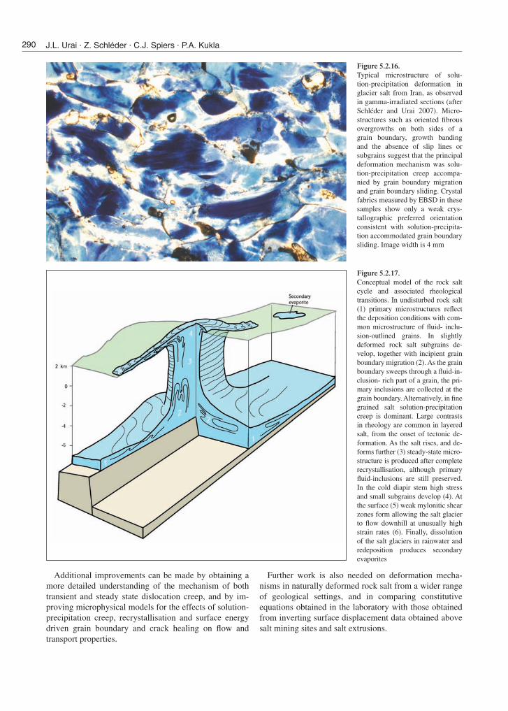
Figure 5.2.16. Typical microstructure of solu-tion-precipitation deformation in glacier salt from Iran, as observed in gamma-irradiated sections (after Schléder and Urai 2007). Micro-structures such as oriented fibrous overgrowths on both sides of a grain boundary, growth banding and the absence of slip lines or subgrains suggest that the principal deformation mechanism was solu-tion-precipitation creep accompa-nied by grain boundary migration and grain boundary sliding. Crystal fabrics measured by EBSD in these samples show only a weak crys-tallographic preferred orientation consistent with solution-precipita-tion accommodated grain boundary sliding. Image width is 4 mm
Figure 5.2.17. Conceptual model of the rock salt cycle and associated rheological transitions. In undisturbed rock salt (1) primary microstructures reflect the deposition conditions with com-mon microstructure of fluid- inclu-sion-outlined grains. In slightly deformed rock salt subgrains de-velop, together with incipient grain boundary migration (2). As the grain boundary sweeps through a fluid-in-clusion- rich part of a grain, the pri-mary inclusions are collected at the grain boundary. Alternatively, in fine grained salt solution-precipitation creep is dominant. Large contrasts in rheology are common in layered salt, from the onset of tectonic de-formation. As the salt rises, and de-forms further (3) steady-state micro-structure is produced after complete recrystallisation, although primary fluid-inclusions are still preserved. In the cold diapir stem high stress and small subgrains develop (4). At the surface (5) weak mylonitic shear zones form allowing the salt glacier to flow downhill at unusually high strain rates (6). Finally, dissolution of the salt glaciers in rainwater and redeposition produces secondary evaporites
290 J.L. Urai · Z. Schléder · C.J. Spiers · P.A. Kukla