flood routing for a specific orientation of … · flood routing for a specific orientation of...
TRANSCRIPT

http://www.iaeme.com/JCIET/index.asp 1 [email protected]
Journal of Civil Engineering and Technology (JCIET) Volume 4, Issue 2, July-December 2017, pp. 1–12, Article ID: JCIET_04_02_001
Available online at http: //www.iaeme.com/jciet/issues.asp?JType=JCIET&VType=4&IType=2
ISSN Print: 2347-4203 and ISSN Online: 2347-4211
© IAEME Publication Scopus Indexed
FLOOD ROUTING FOR A SPECIFIC
ORIENTATION OF PLANNED DEVELOPMENTS
FOR AL-SHAMIYA RIVER IN IRAQ AS CASE
STUDY
Imad Habeeb Obead
Asst. Prof, Civil Engineering Department,
College of Engineering-University of Babylon, Hilla-Iraq
Aliaa Adnan Khodaier
M.Sc. Graduate Student-Civil Engineering
Department-College of Engineering-University of Babylon, Hilla-Iraq
ABSTRACT
Flood routing in branched rivers is an important issue in open channel hydraulic.
Consequently, in this work the simulation of flood waves was performed in Al-Shamiya
branched River, a fully hydraulic approach was involved by solving the Saint Venant
equations using a four-point implicit finite difference scheme as a numerical method.
HEC-RAS software was used to conduct the solution of flood routing problem, the
hydraulic model of Al-Shamiya river included a main channel with total of 12 cross
sections for main channel. The model was calibrated Manning's roughness coefficient
adopted herein of (n=0.04) led to the best agreement between the calculated and
observed data for the Al-Shamiya river in study area for main reach, also the time
weighting factor was (θ=1). The present results indicate that the proposed hydraulic
control approach was by deepening the reach by (0.42 m) and modifying the side slopes
by (5:1, and 7:1) respectively for control section, or constructing compound section by
adding extended berms with filling embankments.
Key words: Flood Routing; Saint Venant Equations; Hydraulic Control; Al-Shamiya
River.
Cite this Article: Imad Habeeb Obead and Aliaa Adnan Khodaier, Flood Routing For
A Specific Orientation of Planned Developments For Al-Shamiya River In Iraq As Case
Study, Journal of Civil Engineering and Technology, 4(2), 2017, pp. 1–12.
//www.iaeme.com/jciet/issues.asp?JType=JCIET&VType=4&IType=2

Imad Habeeb Obead and Aliaa Adnan Khodaier
http://www.iaeme.com/JCIET/index.asp 2 [email protected]
1. HYDRAULIC ROUTING METHODOLOGY
Hydraulic flood routing approaches employ conventional Saint Venant equations with both
continuity and momentum equations. The continuity equation is [1]:
���� + ��
�� = ±q (1)
and the momentum equation is:
���� + �
� ��.��� � + g. A ���
� + S�� = 0 (2)
in which Q is the flow rate; A is the cross-section area; q is lateral inflow/outflow per unit
length; and h is the head of water:
h= z+y, where y is the water depth, and z is the elevation of the river bed bottom above an
arbitrary datum such as mean sea level. x is the distance along the channel; Sf is the friction
slope; and g is the gravitational acceleration; β momentum correction coefficient; and (t) is
time. Equations 1 and 2 represent a system of nonlinear hyperbolic partial differential
equations, for which analytical solutions can only be obtained under certain linearization
assumptions for simple channel geometries and boundary conditions [2].
2. NUMERICAL SOLUTION METHOD
In this research, the weighted four-point implicit finite difference method is selected to solve a
Saint Venant equations for its versatility and computing efficiency. The numerical method was
performed to the Al-Shamiya branched River at the reach from Shamiya Barrage with reach
length of 31.517 Km. to conduct analysis of the following parameters: maximum flood wave
discharge, maximum flood wave elevation, and time of arrival of flood wave to a major section
along the river in a case study as shown in figure (1).
Figure (1) Schematic diagram of the Al-Shamiya branched river
The reach was divided into (55) cross sections, the location of the cross-sections on Shatt-
AL-Shamiya and the lengths of sub reaches were illustrated in Table (1) below.

Flood Routing For A Specific Orientation of Planned Developments For Al-Shamiya River In Iraq As
Case Study
http://www.iaeme.com/JCIET/index.asp 3 [email protected]
Table (1) Location of the cross-sections along AL-Shamiya river [4]
Section No. Station Location (km) Sub-reach Length (m)
1 0+00 1455
5 1+455
10 4+309 3177
15 7+486
20 11+013 3586
25 14+599
30 17+389 4067
35 21+456
40 24+568 3112
45 26+795
50 29+386 2131
55 31+517
The approximations of the derivatives and constant terms in the four point weighted
difference scheme were performed as follows:
(1) The space derivative of Saint-Venant equations approximated as:
���� = � �������������
∆����/� + (1 − �) ����� ����∆����/� (3)
�%�� = � %�������%����
∆����/� + (1 − �) %���� �%��∆����/� (4)
��� �&.��
' � = �(
()*+.,�- .���
���� (()*+.,�
- .����
∆����/� + (1 − �)(
()*+.,�- .���
� � (()*+.,�
- .��
∆����/� (5)
(2) The time derivatives in Saint-Venant equations (Continuity) were approximated as:
�'�/ = '�������'����
0∆/� + '�����'��0∆/� (6)
���/ = �������������
0∆/� + ���������0∆/� (7)
The friction slope Sf is modeled with Manning’s formula:
12 = 13 = ��4�'�56/7 (8)
Where; Sο is the channel bed slope; n is the Manning coefficient, and R is the hydraulic
radius(R=A/P), in which P is the wetted perimeter as shown in figure (2).
Figure (2) Definition sketch of the wetted perimeter P, wetted area A, and top width T of an open
channel cross section

Imad Habeeb Obead and Aliaa Adnan Khodaier
http://www.iaeme.com/JCIET/index.asp 4 [email protected]
There are other ways of representing the Saint-Venant equations which were based upon
the same hypothesis but expressed in terms of different set of dependent variables. Hence, the
water depth (y) in Eq. (2) can be replaced by the water surface elevation (h), The derivative of
(h) with respect to the longitudinal axis (x) along the channel yields:
�%�� = �8
�� + �9�� (9)
Since[�9�� = −1;];
�%�� = �8
�� − 1; (10)
Therefore; the momentum equation can be now expressed in term of (h) by using Eq. (10)
in Eq. (2). Finally, neglecting lateral seepage and lateral overland flow per channel length (q),
the constant terms were approximated as:
12)=>?/0 = 4@��@�'̅�5@6/7 (11)
B@= = ��>����0 (12)
C̅= = '�>'���0 (13)
D@= = '̅�E@� = '̅�
F@� (14)
G@= = F�>F���0 (15)
Substituting the necessary terms in the continuity equation yields:
'�������'����0∆/� + '�����'��0∆/� + � �������������
∆����/� + (1 − �) ����� ����∆����/� = 0 (16)
Multiplying Eq.(16) by (∆xi+1/2) to take the following form:
�HB=>?I>? − B=I>?J + +(1 − �)HB=>?I − B=IJ + ∆����/�0∆/� KHC=>?I>? + C=I>? − C=>?I − C=IJL = 0 (17)
Again, substituting the necessary terms in the momentum equation and by multiplying this
equation with (∆xi+1/2),which yields:
∆����/�0∆/� KB=>?I>? + B=I>? − B=>?I − B=IL + � M(NB0 C⁄ )=>?I>? − (NB0 C⁄ )=I>? + PC̅=I>?(ℎ=>?I>? − ℎ=I>? +
∆R=>�� . 12=>?/0
I>? )T + (1 − �) U(NB0 C⁄ )=>?I − (NB0 C⁄ )=I + PC̅=I V ℎ=>?I + ℎ=I + ∆R=>�� . 12=>�
�I WX = 0
(18)
The terms with subscript (j) in continuity and momentum equations are known either from
initial conditions or from the solution of Saint-Venant equations at the previous time step. Since
cross sectional area (A) and channel top width (B) are functions of water surface elevation (h),
the only unknown terms in these equations are discharge (Q) and water surface elevation (h) at
the (j+1)th time step at nodes (i) and (i+1) [figure 3]. Therefore, there are only four unknowns
in these equations. All remaining terms are either constants or are functions of these unknowns.
As there are N-1 grids in a time line, a total of [2×(N-1)] equations were formed for one
time line between the upstream and downstream boundary. There are two unknowns (Q and h)
in each of the N nodes giving a total of 2N unknown along each time line. The system of 2(N-
1) equations with 2N unknown require two additional equations to be determinate. These two
additional equations are supplied by the upstream and downstream boundary conditions. The

Flood Routing For A Specific Orientation of Planned Developments For Al-Shamiya River In Iraq As
Case Study
http://www.iaeme.com/JCIET/index.asp 5 [email protected]
resulting system of 2N non-linear equations with 2N unknowns was commonly solved by the
Newton-Raphson iterative technique to handle the non-linearity in the equations [3].
Figure (3) Finite difference discretization of (x-t) solution plane representing 1-D flow domain with
respect to time
4. CASE STUDY
The study area adopted herein is Shatt AL-Shamiya. It was part of Euphrates river in Iraq, the
upstream boundary of our study begin from Shamiya Barrage with reach length of 31.517 Km
and an average bed slope range of (7-12cm/km), in which a part of AL-Kifil/AL-Shanafia
irrigation project. The designed discharge for the barrage is 1200 m3/sec, with upstream level
of 23 m.a.s.l., the Barrage consists of radial steel gates, hydroelectric power plant, and
navigation lock. The downstream of the study area was bounded by Al Khwarneq barrage which
is similar to the Shamiya barrage, but its consist of 5 slots. Table 2 includes all the available
hydraulic and spatial information for AL-Shamiya Barrage [4].
Table (2) Hydraulic characteristics for Al-Shamiya barrage
5. RESULTS AND DISCUSSION
In the present work, hydraulic model was developed using HEC-RAS Version 4.1, which
performed unsteady flow analysis for networked channels. The observed flow hydrograph
accompanying to the steady state flow in control section upstream at the head regulator of Al-
Shamiya River was shown in figure (4). The downstream condition used herein considered at
the downstream end of the Al-Shamiya river observed stages hydrograph shown in figure (5).
Details Value
Location Euphrates river/Iraq
No. and Dimension of slots 6 gates of (6.3×12) m
The radius of radial gates 10.5 m
Methods of gates operation Manually/Electrically
Maximum designed discharge 1200 m3/sec
Maximum designed level U/S 23.5 m.a.s.l.
Normal operation discharge U/S 50-200 m3/s
Barrage sill level D/S 16.5 m.a.s.l.
Hydroelectric power 6 MW

Imad Habeeb Obead and Aliaa Adnan Khodaier
http://www.iaeme.com/JCIET/index.asp 6 [email protected]
Figure (4) Inflow hydrograph for upstream boundary (station No. 1) [after (QWRD), 2016]
Figure (5) Stage hydrograph in downstream boundary (station No.55) [after (QWRD, 2016]
Hydraulic approach involves complex numerical equations with high accuracy however
using a lot of data, especially physical data and river specifications. In the study area, the routed
flood hydrograph produced by the Saint Venant model with an acceptable accuracy in flood
routing required parameters which based on the calibration process performed previously by
researchers, such as time step period (∆t = 1 day), Manning’s coefficient (n =0.04), and finite
difference weighing factor(θ=1).
5.1. Steady State Flow Scenario
According to the Directorate of Water Resources in Qadisiyah Governorate/Iraq, the steady
discharge was (70 m3/sec), the water surface elevation compared to both bank elevations and
full bank elevations per each investigated sections along the reach were shown in figure (6)
below.
Figure (6) Variation of river bank, full bank and water surface elevations for all investigated sections
along the study reach for steady flow
The bank-full discharge at a river cross section is the flow which just fills the channel to the
tops of the banks. Such a discharge therefore marks the condition of incipient flooding [5]. As
illustrated from figure (6), almost all sections along reach were sufficient to hold a steady

Flood Routing For A Specific Orientation of Planned Developments For Al-Shamiya River In Iraq As
Case Study
http://www.iaeme.com/JCIET/index.asp 7 [email protected]
discharge. The last Two section (No.50, and 55) were approaches to critical case with maximum
differences in elevations of (0.63m and 0.53 m) respectively. Figures (7, 8, and 9) were
demonstrated the differences between full-bank and flow water elevations for upstream,
downstream control sections and critical cross-section pointed in station No. (50).
Figure (7) Control section (No.1) in Al-Shamiya barrage for steady discharge scenario
Figure (8) Section (No.50) along Al-Shamiya reach for steady discharge scenario
Figure (9) Control section (No.55) for steady discharge scenario
The deficiency in the riverbank's holding capacity corresponding bank-full levels suggested
by author, which can be written as:
YZ = [1 − �\]�8^\] �_ × 100% = [1 − ∆bcde.
\] _ × 100% (19)
Where; ηD is the deficiency of riverbank's holding capacity, YB is the bank-full elevation
(m), and yn is the normal depth for a specified discharge in a channel (m).Table (3) demonstrated
the deficiencies of each section along the reach.
Table (3) Deficiency of riverbank's holding capacity for different channel sections
Section No. ∆∆∆∆Elev.(m) ηηηηD %
1 6.48 73.6
5 1.81 90.3
10 1.7 90.8
15 1.62 91.1
20 1.57 91.3
Imad Habeeb Obead and Aliaa Adnan Khodaier
http://www.iaeme.com/JCIET/index.asp 8 [email protected]
Section No. ∆∆∆∆Elev.(m) ηηηηD %
25 1.5 91.6
30 1.45 91.8
35 1.35 92.2
40 1.21 92.9
45 1.06 93.6
50 0.63 95.9
55 6.93 67.8
If the peak discharge exceeds the riverbank’s holding capacity, then water would be spread
out into the floodplain. Consequently, the more hazard or insufficient section were pointed from
section No. (5) to section No. (50).
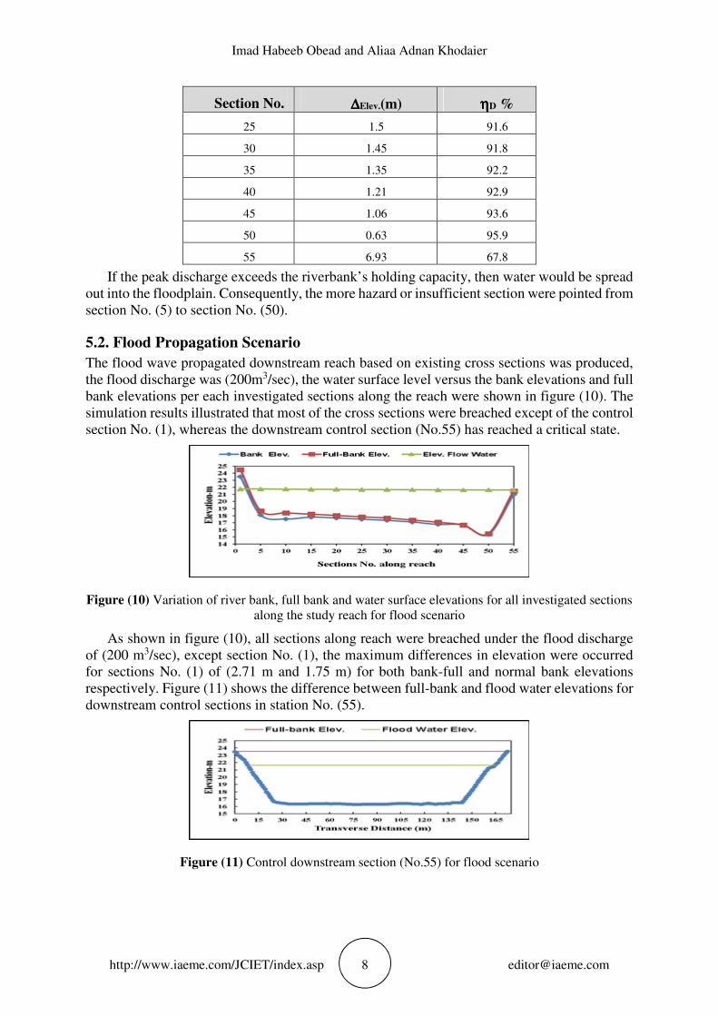
5.2. Flood Propagation Scenario
The flood wave propagated downstream reach based on existing cross sections was produced,
the flood discharge was (200m3/sec), the water surface level versus the bank elevations and full
bank elevations per each investigated sections along the reach were shown in figure (10). The
simulation results illustrated that most of the cross sections were breached except of the control
section No. (1), whereas the downstream control section (No.55) has reached a critical state.
Figure (10) Variation of river bank, full bank and water surface elevations for all investigated sections
along the study reach for flood scenario
As shown in figure (10), all sections along reach were breached under the flood discharge
of (200 m3/sec), except section No. (1), the maximum differences in elevation were occurred
for sections No. (1) of (2.71 m and 1.75 m) for both bank-full and normal bank elevations
respectively. Figure (11) shows the difference between full-bank and flood water elevations for
downstream control sections in station No. (55).
Figure (11) Control downstream section (No.55) for flood scenario

Flood Routing For A Specific Orientation of Planned Developments For Al-Shamiya River In Iraq As
Case Study
http://www.iaeme.com/JCIET/index.asp 9 [email protected]
5.3. Hydraulic Control along Reach
5.3.1. Deepening Critical Sections along the Reach
One of the specified development plan of Al-Shamiya reach involves increasing its lower bound
normal operation upstream discharge from (20 m3/sec) to (75 m3/sec). Figure (12) shows the
critical section corresponding this state of operation, with the most appropriated trapezoidal
section containing the entire existing flow area prior to hydraulic control process. The
inclination angle of left side slope of trapezoidal section is (θ1= 83.3ο), while the inclination
angle of right side slope of trapezoidal section is (θ2=78.7ο), the bed width is (B= 51.6 m), and
the depth of water about (2 m).
Figure (12) Critical section corresponding steady state flow of (75 m3/sec)
To make control on the reach considered in present work, different values of bed levels for
critical cross section No. (50) can be taken and used in the HEC-RAS. Herein, the value was
less than the values of the existing bed levels by (∆=1.047-0.63=0.417m), thus the bed level
was( 12.933 m)and corresponding elevation of flow water was obtained to be (14.41
m).Consequently, the riverbank holding capacity improved by decreasing ηD from 95.9% to
94.1%.
5.3.2 Modifying Channel side slope (H: V)
For practical purposes and implementation requirements, a proper side slope was considered to
be in convenient with downstream control section No. (55) as a sufficient section for steady
flow condition. Figure (13) shows the improved section No. (50) with a combination of
increment in flow depth, and side slopes (, where left side slope of (5:1) and right side slope of
(7:1) respectively.
Figure (13) Improved trapezoidal cross section for steady flow condition
The hydraulic and geometric properties of both existing irregular section and most
appropriated trapezoidal cross section were given in table (4).

Imad Habeeb Obead and Aliaa Adnan Khodaier
http://www.iaeme.com/JCIET/index.asp 10 [email protected]
Table (4) Hydraulic and geometric properties for critical section (No.50) with hydraulic control
5.4. Hydraulic Geometry Due to Flood Flow
By performing HEC-RAS run for flood flow condition for (16 days) and with fixing all the
values of the other parameters, it was found that the flood water level would be (22.02 m.a.s.l.)
in section No. (50) at the beginning of the twelfth day, as shown in figure (14) below.
Figure (14) Obtained stage elevation hydrographs (m.a.s.l.) for different time steps (∆t) during flood
period in critical section No. (50)
Thus, the hydraulic control of breached sections along reach (among many possible options)
will be based on enlarge the improved trapezoidal section shown in figure (13) above to hold
the exceed water quantity produced by flood wave. Otherwise, it would create back water effect
that may endanger the surroundings of the reach. The extra flow area was provided to new
section by mean of fill embankment along the critical sections (from No.5 to No. 50) to provide
berm. The berm was provided in such a way that the bed line and bank line were maintained
parallel:
Gf = g(h2 − hi)g × j? (20)
In which; Bw is the berm width (m), Zf is the fill side slope, Zc is the cut side slope, and d1
is the full bank depth (m). For channels with silt laden water, the actual capacity of the channel
is worked out with 2:1 side slopes in filling, i.e., Zf =2.
Let Bw1 is left side berm width:
Gf? = |(2 − 5)| × 1.98 = 5.94 q
Then, the left side berm width = 6.0 m
Let Bw2 is right side berm width:
Gf0 = |(2 − 7)| × 1.98 = 9.90 q
Section
No.
Cross section
Shape
Full-bank
depth(m)
Water
depth(m)
Wetted
Perimeter P(m)
Flow Area
A(m2)
Hydraulic
Radius
R(m)
Remarks
50
Irregular 1.98 1.98 77.47 101.56 1.31 Non-sufficient
Trapezoidal
(depth increment ) 2.397 1.48 78.67 112.82 1.43 Sufficient, non-applicable
Trapezoidal
(combination) 2.897* 1.30 75.68 199.78 1.66 Sufficient, and applicable
55 Irregular 7.49 1.06 174.08 894.5 5.45 Sufficient for steady and
flood conditions
* with free-board of (0.5m)

Flood Routing For A Specific Orientation of Planned Developments For Al-Shamiya River In Iraq As
Case Study
http://www.iaeme.com/JCIET/index.asp 11 [email protected]
Then, the right side berm width = 10.0 m. therefore, and to approve the implementation
requirements, using the same side berm width of (10.0m). Let the full depth of channel section
is (Df), thus:
Df = flood water level-channel bed level = 22.02-13.35= 8.67 m.
A schematic compound cross section for modified section No.50 of full bank flow condition
was shown in figure (15) below. Some comparative characteristics for sections along studied
reach were summarized in table (5) below.
Figure (15) A typical schematic of improved cross-section (not to scale)
Table 5 Characteristics of breached sections and improved one along studied reach for flood condition
Section No. Flow Area (m2) Wetted perimeter P(m) Hydraulic radius R(m)
5-45* 817.58 127.90 6.40
50 874.20 128.0 6.83
* values are averages for hydraulic parameters.
5.5 Conclusions
From the point of view hydraulic, the relevant treatments of study problem, can be summarized:
• The results obtained herein illustrated that the most applicable hydraulic treatment, would be
deepening the reach by about (0.42m) and modifying exist side slopes of critical cross section
by (5:1, and 7:1) respectively to be sufficient to steady flow conditions (long return period).
• Operating the reach such that the (75 m3/sec) discharge will produce a water level downstream
the AL-Shamiya reach of (14.41 m) at km (29.386).
• Alternative treatment for flood flow (of short return period) scenario was proposed by presented
a compound section adding extended berms and extra flow area to previous cross section by
using fill embankments.

Imad Habeeb Obead and Aliaa Adnan Khodaier
http://www.iaeme.com/JCIET/index.asp 12 [email protected]
REFERENCES
[1] Chanson, H., (2004), Environmental Hydraulics of Open Channel Flows, Elsevier
Butterworth Heinemann, Linacre House, Jordan Hill, Oxford.UK.
[2] Orouji, H., Haddad, O. B., Mehdipour, E. F., and Marino, M. A., (2012), Flood routing in
branched river by genetic programming, Water Management, Proceedings of the Institution
of Civil Engineers, ICE Publishing, http://dx.doi.org/10.1680/wama.12.00006.
[3] Chow, V. T., Maidment, D. R., and Mays, L. M., (1988), Applied Hydrology, McGraw-
Hill, Inc.
[4] QWRD (Qadisiya Water Resource Directorate, Ministry of Water Resources, Iraq.), (2016),
“Report about Shatt Al-Shamyia.
[5] Kalpalatha.Ganamala and P. Sundar Kumar, A Case Study on Flood Frequency Analysis,
International Journal of Civil Engineering and Technology, 8(4), 2017, pp. 1762-1767.
[6] Rituparna Choudhury, B.M. Patil, Vipin Chandra, Uday B. Patil and T. Nagendra,
Assessment of Flood Mitigation Measure For Mithi River – A Case Study, International
Journal of Civil Engineering and Technology, 7(3), 2016, pp. 56–66.
[7] Williams, G. P., (1978), Bank-Full Discharge of Rivers, Water Resources Research,
Volume 14 (6).
[8] Chow, V. T., (1959), Open-Channel Hydraulics, McGraw-Hill Book Company.