floating trail bridges and docks trail bridges and docks. ii table of contents ... most floating...
TRANSCRIPT
Floating Trail Bridges and Docks
United StatesDepartment ofAgriculture
Forest Service
Technology &DevelopmentProgram
2300 RecreationJuly 20020223-2812P-MTDC
In cooperationwith
United StatesDepartment ofTransportation
Federal HighwayAdministration
UN
ITE
D STAT E S O F A MER
ICA
DEP
ARTM
ENT OF TRANSPORTATION
You can order a copy of this document using the order form on the FHWA’s Recreational Trails Program Web site at:
http://www.fhwa.dot.gov/environment/trailpub.htm
Fill out the order form and fax it to the distributor listed on the form. If you do not have Internet access, you can send a fax
request to 202–366–3409, or request by mail from:
USDOT, Federal Highway AdministrationOffice of Human Environment, Room 3301400 7th St. SW • Washington, DC 20590
Produced by:
USDA Forest Service • Missoula Technology and Development Center5785 Hwy. 10 West • Missoula, MT 59808-9361
Phone: 406–329–3978 • Fax: 406–329–3719E-mail: [email protected]
This document was produced in cooperation with the Recre-ational Trails Program of the Federal Highway Administration, U.S. Department of Transportation.
This document is disseminated under the sponsorship of the U.S. Department of Transportation in the interest of information exchange. The United States Government assumes no liability for its contents or use thereof.
The contents of this report reflect the views of the contractor, who is responsible for the accuracy of the data presented herein. The contents do not necessarily reflect the official policy of the Department of Transportation.
This report does not constitute a standard, specification, or regulation. The United States Government does not endorse products or manufacturers. Trade or manufacturer’s names appear herein only because they are considered essential to the object of this document.
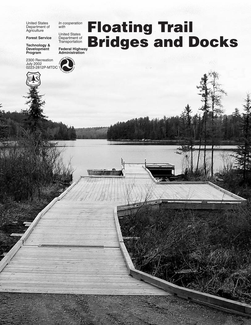
Cover—A boardwalk on the Superior National Forest is used to traverse a bog to a dock on open water (Photo by Daniel Hernesmaa, USDA Forest Service).
UN
ITE
D STAT E S O F A M
ERIC
A
DEP
ARTM
ENT OF TRANSPORTATION

Jasen NeeseNatural Resources Specialist
Merv ErikssonRegional Bridge EngineerUSDA Forest Service, Pacific Northwest Region
Brian VachowskiProject Leader
USDA Forest ServiceTechnology and Development ProgramMissoula, MT
2E22A44—Floating Bridge Used for Multipurpose Trails
July 2002
The Forest Service, United States Department of Agriculture (USDA), has developed this information for the guidance of its employees, its contractors, and its cooperating Federal and State agencies and is not responsible for the interpretation or use of this information by anyone except its own employees. The use of trade, firm, or corporation names in this document is for the information and convenience of the reader and does not constitute an endorsement by the Department of any product or service to the exclusion of others that may be suitable.
The U.S. Department of Agriculture (USDA) prohibits discrimination in all its programs and activities on the basis of race, color, national origin, age, disability, and where applicable, sex, marital status, familial status, parental status, religion, sexual orientation, genetic information, political beliefs, reprisal, or because all or part of an individual’s income is derived from any public assistance program. (Not all prohibited bases apply to all programs.) Persons with disabilities who require alternative means for communication of program information (Braille, large print, audiotape, etc.) should contact USDA’s TARGET Center at (202) 720-2600 (voice and TDD). To file a complaint of discrimination, write to USDA, Director, Office of Civil Rights, 1400 Independence Avenue, S.W., Washington, D.C. 20250-9410, or call (800) 795-3272 (voice) or (202) 720-6382 (TDD). USDA is an equal opportunity provider and employer.
Floating Trail Bridges and Docks

ii
Table of Contents
Introduction ___________________________________________________________________1 Floating Bridges ____________________________________________________________________________ 1 Siting Considerations ________________________________________________________________________ 1 Accessible Trails ____________________________________________________________________________ 2 Accessible Boat Docks _______________________________________________________________________ 2 Military Floating Bridges _____________________________________________________________________ 2 Floating Docks ______________________________________________________________________________ 3
Floating Bridge and Dock Components ____________________________________________4
Floating Dock Materials _________________________________________________________5 Wood ______________________________________________________________________________________ 5 Metal ______________________________________________________________________________________ 6 Alternative Materials _________________________________________________________________________ 7
Modular Floats (Modules) _______________________________________________________10
Alternatives to Floating Structures _______________________________________________ 11 Cantilever Docks ___________________________________________________________________________ 11 Crib Docks ________________________________________________________________________________ 11 Concrete Piers _____________________________________________________________________________ 11 Pile Docks and Piers ________________________________________________________________________ 11 Pipe Docks ________________________________________________________________________________ 12 Suspension Docks _________________________________________________________________________ 12
Design of Floating Structures ___________________________________________________13 Decks ____________________________________________________________________________________ 13 Frames ___________________________________________________________________________________ 13 Floats ____________________________________________________________________________________ 14 Hardware and Connectors ___________________________________________________________________ 15 Anchorage Connections _____________________________________________________________________ 15
Anchorage System Design ______________________________________________________17 Submerged Anchor Cable Systems ____________________________________________________________ 17 Shoreline Anchor Cable Systems _____________________________________________________________ 18 Overhead Anchor Cable Systems _____________________________________________________________ 19 Pile Anchorages ____________________________________________________________________________ 19 Spud Anchorages __________________________________________________________________________ 21 Rail Anchorages ___________________________________________________________________________ 21
Shore Anchorage and Access ___________________________________________________23 Shoreline Access ___________________________________________________________________________ 23 Shoreline Anchorage ________________________________________________________________________ 23
Additional Information _________________________________________________________25 Dock and Float Suppliers ____________________________________________________________________ 25 Wood Preservative Resources and Documents __________________________________________________ 25 Pontoons and Metal Floats ___________________________________________________________________ 26 Military Documents _________________________________________________________________________ 26 References ________________________________________________________________________________ 26
1
TIntroduction
T he Missoula Technology and Development Center (MTDC) was asked to evaluate the use of floating bridges for trail crossings in very wet areas. This
report outlines the basic designs of floating structures. It includes information about floating boat docks, floating bridge designs, anchorage systems, and devices that allow the dock to adjust itself to varying water levels.
Floating bridges are generally not feasible for equestrian and livestock use because the bridges move. Floating bridges should generally be a structure of last resort, used only for crossing ponds, marshes, swamps, bogs, or similar areas that are too wet for more traditional, less costly trail bridges or for other wetland trail construction techniques.
Floating bridges have been used in military operations for the past 2,500 years. Floating docks are more modern, but they are common in all parts of the United States. A dock is essentially a bridge connected to land at only one end. Design concepts and applications for floating docks are applicable for floating bridges. In this report the term “floating structures” will apply to either a floating bridge or a floating dock.
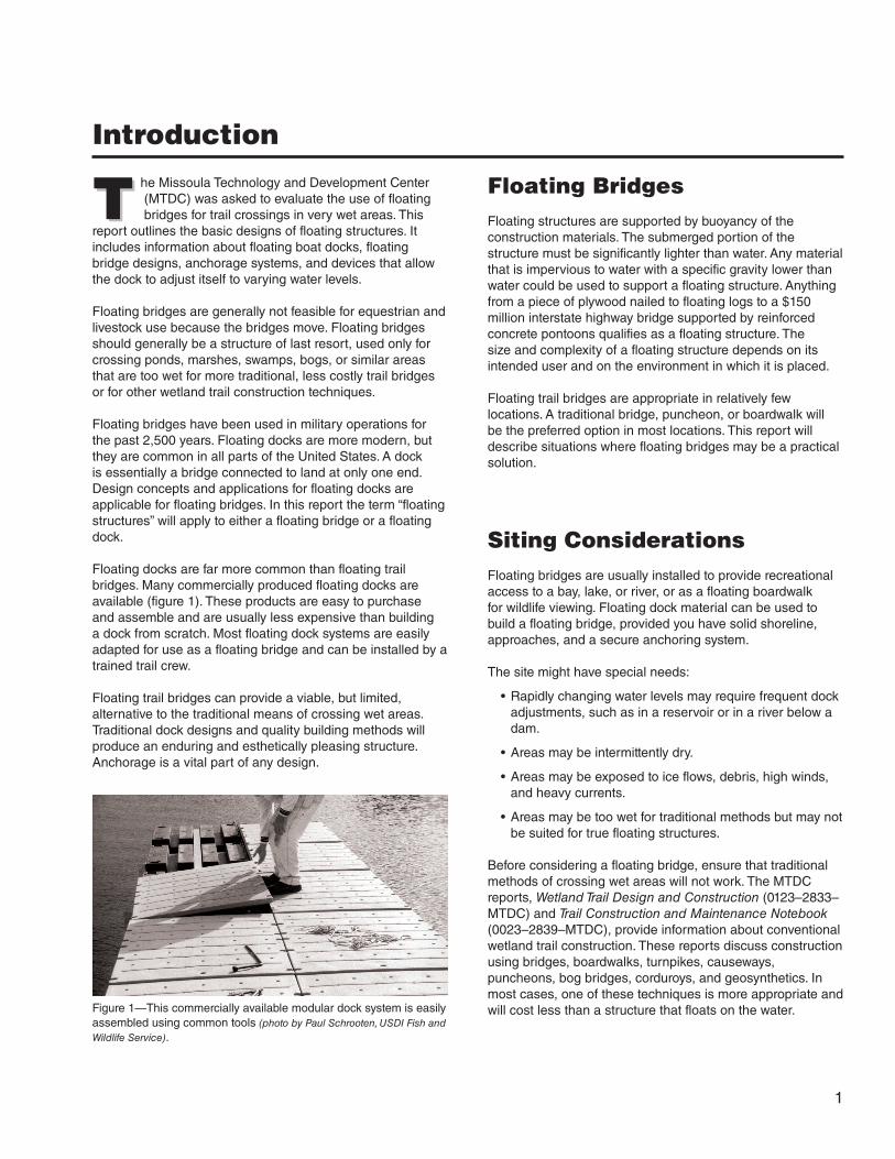
Floating docks are far more common than floating trail bridges. Many commercially produced floating docks are available (figure 1). These products are easy to purchase and assemble and are usually less expensive than building a dock from scratch. Most floating dock systems are easily adapted for use as a floating bridge and can be installed by a trained trail crew.
Floating trail bridges can provide a viable, but limited, alternative to the traditional means of crossing wet areas. Traditional dock designs and quality building methods will produce an enduring and esthetically pleasing structure. Anchorage is a vital part of any design.
Floating BridgesFloating structures are supported by buoyancy of the construction materials. The submerged portion of the structure must be significantly lighter than water. Any material that is impervious to water with a specific gravity lower than water could be used to support a floating structure. Anything from a piece of plywood nailed to floating logs to a $150 million interstate highway bridge supported by reinforced concrete pontoons qualifies as a floating structure. The size and complexity of a floating structure depends on its intended user and on the environment in which it is placed.
Floating trail bridges are appropriate in relatively few locations. A traditional bridge, puncheon, or boardwalk will be the preferred option in most locations. This report will describe situations where floating bridges may be a practical solution.
Siting ConsiderationsFloating bridges are usually installed to provide recreational access to a bay, lake, or river, or as a floating boardwalk for wildlife viewing. Floating dock material can be used to build a floating bridge, provided you have solid shoreline, approaches, and a secure anchoring system.
The site might have special needs:
• Rapidly changing water levels may require frequent dock adjustments, such as in a reservoir or in a river below a dam.
• Areas may be intermittently dry.
• Areas may be exposed to ice flows, debris, high winds, and heavy currents.
• Areas may be too wet for traditional methods but may not be suited for true floating structures.
Before considering a floating bridge, ensure that traditional methods of crossing wet areas will not work. The MTDC reports, Wetland Trail Design and Construction (0123–2833–MTDC) and Trail Construction and Maintenance Notebook (0023–2839–MTDC), provide information about conventional wetland trail construction. These reports discuss construction using bridges, boardwalks, turnpikes, causeways, puncheons, bog bridges, corduroys, and geosynthetics. In most cases, one of these techniques is more appropriate and will cost less than a structure that floats on the water.Figure 1—This commercially available modular dock system is easily
assembled using common tools (photo by Paul Schrooten, USDI Fish and Wildlife Service).
2
If there is too much water for traditional techniques, floating structures should be considered. A floating bridge can be designed to carry trail bridge loads for relatively short distances. The types of environments where floating bridges are feasible include bogs, swamps, lakes, bays, and very slow-moving bodies of water. Conventional bridges are needed to span streams with substantial currents. Floating bridges work best in the following conditions:
• Low flow velocities, usually less than 0.25 feet per second. The upper limit of velocity depends on the structure’s design and the anchorage. Many manufacturers can provide information to calculate the upper limit of flow velocity for a particular design. Military documents listed in the Additional Information section provide detailed discussion on this subject.
• No significant debris flowing in the stream.
• Exposure to no more than gentle wave action. Most designs with proper anchorage can withstand typical waves on lakes and waves caused by boat wakes.
• Minimal ice formation. Unless floating structures are designed specifically to withstand the rigors of icy conditions, most will need to be removed before freezeup.
The site should be mapped and inventoried before a floating structure is constructed. The inventory should include:
• Possible floating bridge locations
• Types and amount of expected use
• Existing recreational, commercial, scientific, or other forest uses
• Water levels (high and low), water depth, wave heights, and current direction and velocity
• Ownership boundaries
• Navigational and recreational hazards
• Prevailing wind direction and strength
• Land and aquatic flora and fauna (especially endangered or threatened species)
• Existing Recreational Opportunity Spectrum classification of the trail and surrounding area
• Environmental concerns
• Anchorage points
To locate the floating bridge in the best possible site, select the trail location last. The bridge is likely to be more expensive and difficult to site than the trail.
Accessible TrailsTrails need to be accessible to people of differing abilities. All trails do not have to be accessible to all people, but accessibility is to be considered for new trail construction and reconstruction of trails managed for pedestrian use. If a segment of a pedestrian trail has a bridge, and that trail segment is intended to be accessible, the bridge also needs to be accessible.
The Federal Access Board’s draft report on Accessibility Guidelines for Outdoor Developed Areas provides general guidance on trail accessibility. It is available at: http://www.access-board.gov/outdoor/outdoor-rec-rpt.htm. The U.S. Department of Agriculture (USDA) Forest Service also has trail accessibility guidelines, intended for use on national forests. These draft guidelines are available at: http://www.fs.fed.us/recreation/accessibility.
Accessible Boat DocksBoat docks are required to be accessible. Accessibility guidelines for boat docks are available through the Federal Access Board at http://www.access-board.gov in Recreation Facilities Accessibility Guidelines, under the Boating and Fishing Facilities subsection. Call the Access Board’s technical assistance unit, at 800–877–2253, for further assistance in locating these guidelines. If the dock is adjacent to a parking area, toilet facility, or other constructed element of the site, those elements must be accessible and connected by accessible routes.
Military Floating BridgesThe United States military has a wide variety of prefabricated bridge designs ready for deployment. Most military bridges are designed for rapid setup and disassembly so troops and equipment can cross rivers or streams.
For the most part, military floating bridges are big, heavy, and expensive. These structures would not be a good choice for Forest Service recreational use because of their limited availability and need for maintenance. In addition, these bridges would not fit well in a backcountry setting. More information is available in the Additional Information section.
v
Introduciton
3
Floating DocksFloating docks can be easily modified to serve as a floating bridge. Resorts use floating docks to allow access to swimming platforms. In Alaska, the Forest Service and U.S. Department of the Interior (USDI) National Park Service use bridges floating on calm water to access bear-viewing
platforms. In addition, many State recreation departments use floating docks as fishing platforms.
Docks are an efficient way of crossing water barriers. They are designed for pedestrian traffic. With the right modifi-cations (width, buoyancy, stability, and anchorage), they can be adapted for other types of traffic, such as off-highway vehicles (OHVs).
Introduction

4
MFloating Bridge and Dock Components
M anufacturers offer floating docks made from many types of materials. Wood and metal are the most common materials, although docks made of
plastics, fiberglass, and structural composites are becoming available.
Any floating structure is made up of three parts (figure 2):
Deck—The deck is the upper portion of the structure that actually supports the user.
Frame—The frame provides the structural support for the deck.
Floats—The floats replace the bridge abutments or foundation. They provide the buoyancy needed to keep the dock and its users dry.
The three main parts of a floating dock may be made of different materials. For instance, a dock may have a polyethylene float, connected to a galvanized iron frame that supports a pressure-treated wooden deck. Some parts may be combined into one piece. Steel tubing, for instance, may function as both the frame and the float.
Deck
Float
Frame
Figure 2—Most floating structures are composed of three main parts: the deck, the frame, and the floats.

5
Floating Dock Materials
Figure 3—Read the consumer information sheet before working with pressure-treated wood.
WoodWood has many advantages for floating structures. It’s attractive, economical, naturally buoyant, and easy and familiar to work with. Pressure-treated wood or a naturally rot-resistant wood like redwood, cypress, or cedar should be used to ensure a long service life. Health and environmental issues should be considered when using pressure-treated wood.
Most water-based wood preservatives are suitable for human contact and can be applied by staining or painting. Common water-based preservatives include chromated copper arsenate (CCA), ammoniacal copper zinc arsenate (ACZA), or alkaline copper quat (ACQ). A consumer information sheet should be included with any pressure-treated lumber (figure 3).
Pressure treatment forms an envelope of pesticide-impregnated wood that may be less than half an inch thick, protecting the untreated interior portion of the wood. Treating the wood after all cuts and holes have been made will help keep the treated envelope intact and extend the useful life of the structure. Eliminating field sawing and drilling is also critical to minimizing the introduction of harmful chemicals into the environment.
Chemically treated wood may last 40 years or more, five times or more longer than untreated wood. It is important to know which chemical treatments are appropriate, and how they may cause adverse health or environmental effects.
The subject of chemical treatments for wood is not only complex, it is an area of continuing research and product development. The Additional Information section includes several good resources. Always follow the recommendations in the Best Management Practices for the Use of Treated Wood in Aquatic Environments (Western Wood Preservers Institute 1996). Other sources of good information are the Guide for Minimizing the Effects of Preservative-Treated Wood on Sensitive Environments (Lebow and Tippie 2001) and Best Management Practices for the Use of Preservative-Treated Wood in Aquatic Environments in Michigan (Pilon 2002).
There are several good reasons to use properly treated wood in wet areas and few reasons not to. All of the treatments that are effective in wet areas must be applied using pressure treatment at a certified treatment facility. Spots where the wood was cut or drilled in the field can be treated by hand brushing several coats of copper naphthenate. Copper naphthenate is not an U.S. Environmental Protection Agency (EPA)-controlled chemical, so it can be purchased and applied by field personnel. Both oil-based and waterborne preservatives are suitable for preserving wood in wet environments. Know the characteristics and effects of each type of preservative before deciding which one to use. Water-soluble preservatives, such as borates, are not suitable for wet environments. The borates do not permanently “fix” to the wood.
The availability and use of some preservative-treated wood products may change. Under a pending agreement between the EPA and representatives of the wood-preservative industry, chromated copper arsenate will be phased out of residential use. Chromated copper arsenate can still be used in bridge construction, but its availability may be limited.
Workers need to take safety precautions when handling or disposing of treated wood. Treated wood should not be burned. Some States and other jurisdictions may also impose additional restrictions on disposal.
6
Floating Dock Materials
Each of the preservatives containing copper imparts a color that disappears over time, normally within 2 years. But, depending on site conditions and exposure, the color may last for several months to 3 or 4 years. Stains can be added to the waterborne preservatives at the time of treatment or at any time afterward. Pigments, stains, and dyes mask the normal color of the preservative. Because these materials will penetrate the wood during treatment, future needs for restaining will be reduced. Treatment plants will be reluctant to apply special stains to wood unless they are processing a very large order.
Generally, use galvanized, powder-coated, or painted metal fasteners on any wood members.
Untreated, painted wood will require more maintenance and will have a shorter service life. The wood will need a new coat of paint every few seasons. Old, deteriorated paint tends to trap moisture and hasten decay. A finish, if used at all, should soak into the wood rather than coating it.
Good design and construction techniques can reduce wood deterioration. Most fungi that decay untreated wood require four basic conditions for survival:
• Moisture levels higher than the fiber saturation point in the wood
• Free oxygen
• Temperatures from 50 to 90 °F
• Food (the wood)
Wood that is continually submerged will not decay because no oxygen is present. In addition to treatment, another way to slow fungal deterioration is to minimize the time that wood has a high moisture content. Provide ventilation through wood frames and decks. Fit fasteners flush with the wood’s surface to prevent water from accumulating. In general, minimize the areas where water can pool.
Decks—Wood decks remain a popular choice because they are attractive, relatively inexpensive, and easy to assemble and repair. Popular choices include pine, redwood, cedar, cypress, and wood-plastic polymers. Many owners do not treat or paint their decks and allow the wood to age naturally. Untreated decks rot quickly. Decks that are treated with a preservative will last five or more times longer than untreated wood decks.
Frames—Wood has increasingly been replaced by aluminum or galvanized metal for framing, but wood is still common and has many advantages. Wood is easy to work with and
workers are often familiar with good construction practices. A rotten wooden frame member is often easier to replace than a comparable section of rusted metal. Wood may also be more attractive and less expensive. A dock’s frame comes into contact with water or may be constantly submerged in water depending on the design and loading weights. Wood used for dock frames should be pressure-treated with a preservative. Untreated wood that gets wet and is allowed to dry frequently may last just 2 to 3 years. Properly pressure-treated wood is recommended for framing.
Floats—As wood becomes saturated with water it loses strength and buoyancy. Wooden floats should only be used for temporary, primitive bridges.
MetalThe most common metals used in dock fabrication are aluminum, stainless steel, and galvanized steel.
Steel should be painted, galvanized, or coated with an epoxy or ceramic layer to extend its service life. For maximum effectiveness, coatings should be applied in the shop, after fabrication, so the coating extends into grooves and holes.
Aluminum is lightweight and naturally corrosion resistant. When aluminum interacts with oxygen, a surface layer of oxide is produced that protects the aluminum from further degradation. Aluminum members must be thicker than a comparable steel member to provide equivalent strength. Aluminum will corrode when it contacts a dissimilar metal. Aluminum components should not be joined to steel components.
Stainless steel provides the strength of steel and the corrosion resistance of aluminum, but costs several times more than galvanized steel.
Decks—Most floating structures have timber decking instead of metal. Metal decking usually weighs more than wood and may not fit esthetically into less developed settings. However, docks for heavy traffic areas in developed settings or for motorized users may benefit from metal grating or aluminum sheeting on decks (figure 4). The grating provides additional traction, especially during wet and muddy conditions, and will last longer than wood under heavy use.

7
Figure 4—This dock at Dworshak Reservoir in Idaho uses metal grating as its deck. Metal decking provides drainage and traction but can still be slick when it is muddy and wet.
Figure 5—Steel tubing should be framed for adequate structural integrity.
Floating Dock Materials
Frames—Metal framing is becoming increasingly popular. Lightweight aluminum is a good choice for pedestrian traffic. Galvanized frames also work, but the added weight will require more (or larger) floats.
Steel tubing is popular. Steel tubing can function as both the float and the frame. Framing brackets and crossmembers are welded at each end, and at intermediate locations for long structures (figure 5). Brackets are usually welded to the tubes to attach the deck.
Coatings can increase the service life of the steel members. Apply coatings in the shop after fabrication to further increase the steel’s service life. Using thicker steel also increases a structure’s usable life, but increases the weight and the cost.
Floats—Metal floats are usually tubes or drums, but almost any closed shape can be used. Metal floats have the advantages of strength, durability and, if properly coated, longevity. Metal floats are generally called pontoons. Most pontoons are aluminum. The wall thickness depends on the pontoons’ size and use. Many manufacturers or suppliers provide custom pontoons. Most pontoons have multiple individually sealed air chambers, which may or may not be filled with foam. Connection points may be built in, bolted on, or welded. A punctured tube can sink an entire structure. Foam-filled tubes can provide insurance against this catastrophe.
Recycled industrial drums should not be used as flotation pontoons. Their walls are not thick enough for durability and they may contain toxic residues. Consult reputable suppliers to find flotation devices.
Alternative MaterialsA wide variety of materials have been used for docks, including plastics, concrete, fiberglass, and wood/plastic composites (figure 6).
Decks—Many distributors offer decking materials made of wood/plastic composites, vinyl, and other plastics engineered to look and behave like wood. Advantages include less maintenance, and less damage from insects, rot, and moisture. In addition, these materials do not twist, cup, or warp as wood decking commonly does. Plastic decking may be made from recycled material. Disadvantages include higher initial purchase price and closer required spacing of supports than wood decking. Some products require extra care because they are more prone to cracking than wood. Holes may need to be drilled. Sawdust from plastic materials will not decompose. Good practices call for cutting these materials away from water and packing out the shavings.

8
Figure 6—A concrete support makes an excellent foundation.
A Note AboutExpanded Polystyrene Foam (EPS)
The trade name Styrofoam is often used incor-rectly when referring to EPS billets. Styrofoam is a specific type of EPS manufactured by the Dow Chemical Co. The three most common types of EPS are:
• Open-cell EPS
• Molten closed-cell EPS
• Extruded closed-cell EPS (Styrofoam)
Open-cell EPS has an open structure that easily lets water into its interior. It becomes water-logged quickly. Molten closed-cell EPS, while water resistant, is weak and breaks into tiny pieces on impact or while being cut. The internal framework of extruded closed-cell EPS is much like wood, giving it additional strength and water resistance. Forest Service floating structures should only use extruded closed-cell EPS and the foam should be encased in a protective covering.
Floating Dock Materials
Frames—Plastic products are available for frames. The advantages of plastic include water and decay resistance. Because frame materials have no standard specifications, different manufacturers sell different types of materials. Plastic products are usually made from polyethylene formed into many different shapes. The materials usually function as both the float and the frame. Plastic frames often have molded indentations, holes, tunnels, grooves, or brackets that accept common wood decking and reinforcing members. If you are considering using plastic materials, be aware of strength and repair issues. Many different types of manufacturing processes and chemical additives influence a plastic’s strength and durability. Check with the supplier to ensure their product will stand up to its intended use. While plastics can often be repaired if they are damaged, some plastics will require skilled labor to match the appearance and strength of the repaired section to the original member.
Floats—Traditional polystyrene foam blocks or billets must be encased in a protective covering. This material provides excellent flotation, but is susceptible to damage from debris, sunlight, chemicals, and burrowing animals.
Plastic Float Drums—Most common docks use plastic float drums. They are typically constructed of polyethylene by rotational or blown molding. Rotationally molded polyethylene is stronger than polyethylene molded by blowing. Plastic float drums are hollow or may be filled with closed-cell EPS or another type of secondary flotation. Secondary flotation helps absorb shocks during impacts and will reduce the loss of buoyancy if the shell is punctured.
Plastic float drums with EPS inside are an excellent means of flotation. The float drum’s tough polyethylene shell has properties that the EPS lacks, including resistance to impact and stress fractures, protection from rodents, and ultraviolet inhibitors that resist breakdown from solar radiation. Plastic does not react with many chemicals and the EPS core provides flotation insurance in case the plastic shell is penetrated. For most applications rotationally molded plastic float drums filled with extruded closed-cell EPS foam are recommended because of their availability and proven functionality.
9
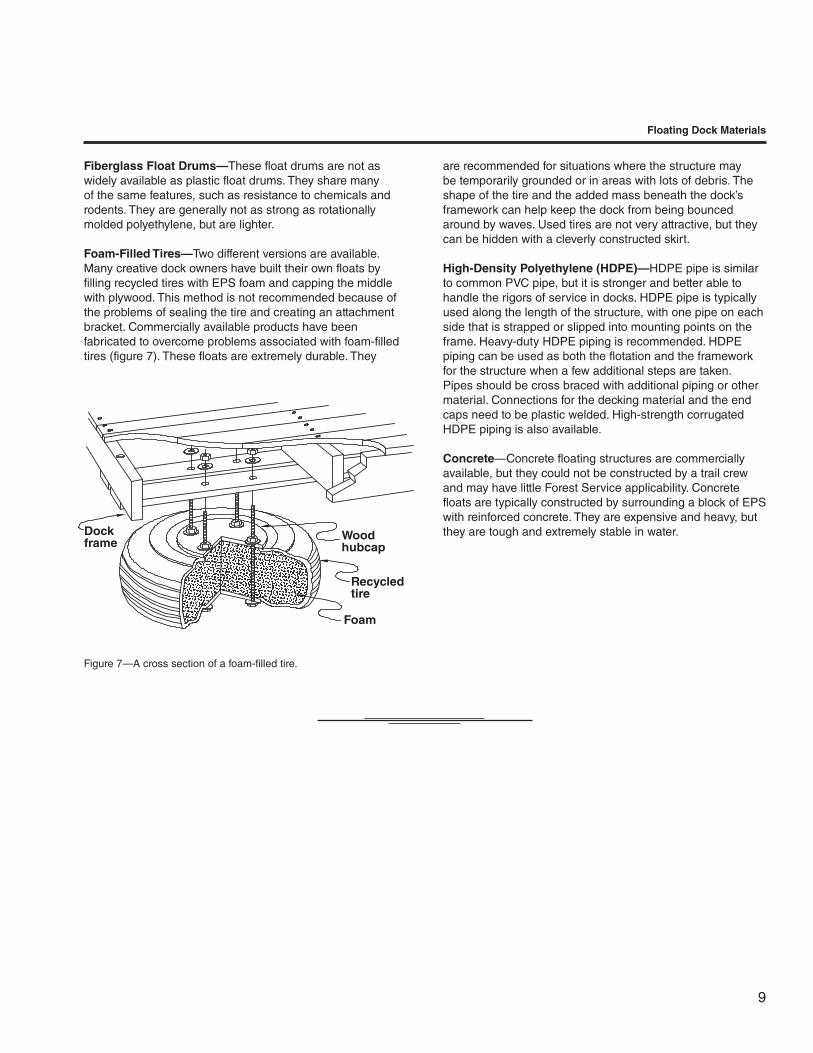
Recycledtire
Dockframe
Woodhubcap
Foam
Figure 7—A cross section of a foam-filled tire.
Floating Dock Materials
Fiberglass Float Drums—These float drums are not as widely available as plastic float drums. They share many of the same features, such as resistance to chemicals and rodents. They are generally not as strong as rotationally molded polyethylene, but are lighter.
Foam-Filled Tires—Two different versions are available. Many creative dock owners have built their own floats by filling recycled tires with EPS foam and capping the middle with plywood. This method is not recommended because of the problems of sealing the tire and creating an attachment bracket. Commercially available products have been fabricated to overcome problems associated with foam-filled tires (figure 7). These floats are extremely durable. They
are recommended for situations where the structure may be temporarily grounded or in areas with lots of debris. The shape of the tire and the added mass beneath the dock’s framework can help keep the dock from being bounced around by waves. Used tires are not very attractive, but they can be hidden with a cleverly constructed skirt.
High-Density Polyethylene (HDPE)—HDPE pipe is similar to common PVC pipe, but it is stronger and better able to handle the rigors of service in docks. HDPE pipe is typically used along the length of the structure, with one pipe on each side that is strapped or slipped into mounting points on the frame. Heavy-duty HDPE piping is recommended. HDPE piping can be used as both the flotation and the framework for the structure when a few additional steps are taken. Pipes should be cross braced with additional piping or other material. Connections for the decking material and the end caps need to be plastic welded. High-strength corrugated HDPE piping is also available.
Concrete—Concrete floating structures are commercially available, but they could not be constructed by a trail crew and may have little Forest Service applicability. Concrete floats are typically constructed by surrounding a block of EPS with reinforced concrete. They are expensive and heavy, but they are tough and extremely stable in water.
10
MModular Floats (Modules)
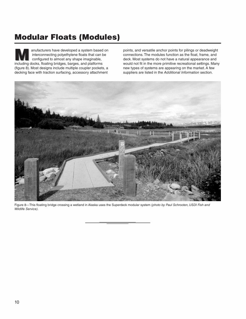
M anufacturers have developed a system based on interconnecting polyethylene floats that can be configured to almost any shape imaginable,
including docks, floating bridges, barges, and platforms (figure 8). Most designs include multiple coupler pockets, a decking face with traction surfacing, accessory attachment
points, and versatile anchor points for pilings or deadweight connections. The modules function as the float, frame, and deck. Most systems do not have a natural appearance and would not fit in the more primitive recreational settings. Many new types of systems are appearing on the market. A few suppliers are listed in the Additional Information section.
Figure 8—This floating bridge crossing a wetland in Alaska uses the Superdeck modular system (photo by Paul Schrooten, USDI Fish and Wildlife Service).
11
SAlternatives to Floating Structures
Some alternatives may be more suitable than floating structures.
Cantilever DocksA cantilever dock typically relies on the shoreline or on a shoreline structure for its entire anchorage (figure 9). Some docks may have intermediate supports very close to the shoreline. The end of a cantilever dock juts out over the water, appearing to float on air. Cantilever docks are suitable for almost any type of environment and have a very small environmental footprint. The shoreline anchorage and framing must be strong enough to support the weight of the dock and its users. Consult a qualified engineer to develop a design suitable for your application.
Figure 9—Cantilever docks do not float on the water.
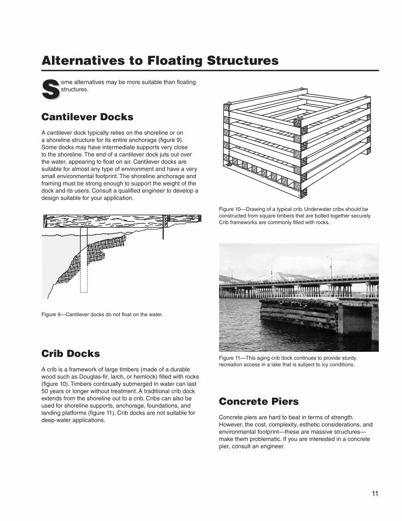
Crib DocksA crib is a framework of large timbers (made of a durable wood such as Douglas-fir, larch, or hemlock) filled with rocks (figure 10). Timbers continually submerged in water can last 50 years or longer without treatment. A traditional crib dock extends from the shoreline out to a crib. Cribs can also be used for shoreline supports, anchorage, foundations, and landing platforms (figure 11). Crib docks are not suitable for deep-water applications.
Figure 10—Drawing of a typical crib. Underwater cribs should be constructed from square timbers that are bolted together securely. Crib frameworks are commonly filled with rocks.
Figure 11—This aging crib dock continues to provide sturdy recreation access in a lake that is subject to icy conditions.
Concrete PiersConcrete piers are hard to beat in terms of strength. However, the cost, complexity, esthetic considerations, and environmental footprint—these are massive structures—make them problematic. If you are interested in a concrete pier, consult an engineer.

12
Alternatives to Floating Structures
Pile Docks and PiersPile docks are very similar to traditional boardwalk structures. They rely on large wood, steel, or concrete piles to support them above the water (figure 12). Piling design must be left to a qualified engineer. The MTDC report, Wetland Trail Design and Construction (0123–2833–MTDC), contains some discussion about installing piles.
Concretepad
Pipe DocksPipe docks are similar to pile docks. However, the deck and frame rest on 1.5- to 3-inch-diameter metal pipes rather than on large piles. The metal pipes rest on supports placed on the bottom of the waterway (softer bottoms need wider supports), as shown in figure 13. Pipe-supported decks are not suitable for deep water. Water depth should not exceed the width of the deck. The frame and deck ride above the water level, making the pipe dock an excellent means of crossing swift water (be aware of possible scouring at the pipe’s base) and areas with environmental concerns. Only the metal legs come in contact with the water. Pipe legs should be cross braced and bracketed on the frame for added support. Most pipe dock designs are easily adjusted and removable.
Figure 14—Suspension docks, when properly designed and built, can provide many years of use. A suspension dock can be designed so it can be raised and lowered.
Figure 13—A drawing of a dock supported by pipe legs. Pipe-leg-based structures are one of the most environmentally gentle ways of crossing wet areas.
Figure 12—Small pile-based docks (finger docks) reaching out from the main dock offer access during periods of high water.
Suspension DocksPicture a suspension bridge cut in half and you have a suspension dock (figure 14). The shoreline end is hinged to a solid landing. Cables are run from a shoreline anchor over a tower to connection points on the dock. Suspension docks are suitable for most settings so long as anchorage is adequate and the structure is strong enough. Use engineering assistance to design a suspension dock.

13
SDesign of Floating Structures
Figure 15—Side extensions to this floating trail bridge provide places where users can stop without obstructing others (photo by Paul Schrooten, USDI Fish and Wildlife Service).
S ite conditions may force you to modify a prefabricated dock or even to design your own floating structure. This report is limited to small,
simple structures and is not intended to cover the details of planning and designing floating bridges. Floating trail bridges should be designed by a qualified engineer. The Forest Service Manual delegates authority for trail bridge design to the forest engineer.
For more information, consult books on dock building, military manuals, and experienced dock builders and engineers. The following sections provide general information about the design of floating structures.
DecksFour elements need to be considered when designing the deck: width, structural adequacy, traction, and appearance. The deck needs to be wide enough to carry its intended users. In most cases decks should be handicapped accessible. A wider deck provides a feeling of security and safety and is more stable. A bridge should be at least as wide as the trail leading to it. The absolute minimum width is 3 feet; 4 feet is the minimum recommended width. If users might congregate on the structure, the deck may need to be wider or an additional section may be attached to the side of the deck to provide room where users can stop while others move by (figure 15).
Decking material must be strong enough to prevent failure and stiff enough to give a feeling of stability. Additional framing support may be needed for plastic or thin wooden decking. Strength is even more important if the decking also serves as the frame or is used to connect to anchorage supports.
Deck material should not be slippery. A floating structure is often muddy and wet. Plastic or metal gratings allow mud and water to flow through, leaving the grating’s surface dry. Timber planks should be spaced at least 1⁄ 2 inch apart to allow for drainage. Planks that are 4 to 8 inches wide generally work best for decking. When additional traction is needed, try painting the planks with an antiskid paint, gluing sand to the deck, securing rubber matting to the deck, or mounting timber cleats on the deck. When designing the deck surface, consider the deck’s intended users, the Recreation Opportunity Spectrum setting, and any accessibility requirements. Make sure that the surfacing will not catch the tires of bicycles or wheelchairs.
Appearance is important. Deck overhangs, which hide the floats, are encouraged, but should not reduce the strength of the decking or the stability of the structure. Decking is the most visible part of a floating bridge or dock. A rustic deck can often hide or disguise the appearance of a modern frame or floats. The Missoula Technology and Development Center’s Trail Bridge Catalog (available to Forest Service and USDI Bureau of Land Management employees at http://fsweb.mtdc.wo.fs.fed.us/bridges and to the public at http://www.fwha.dot.gov/environment/trailpub.htm) contains styles of bridge decks for different Recreation Opportunity Spectrum classes.
FramesIn most designs the frame bears the brunt of the forces placed on the structure. These forces include vertical forces from users and wave action as well as lateral forces from wind, currents, boats, and debris. Connections securing the frame to the floats, and the deck to the frame, are critical.
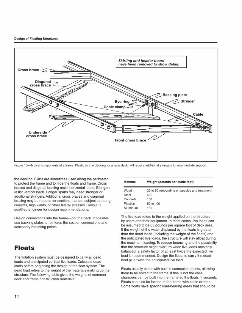
Dock frames are similar to the superstructure of a traditional trail bridge. At least two longitudinal stringers provide the main structural integrity. The stringers’ spacing determines the thickness of the decking (figure 16). Cross braces or floor beams are placed between, or under, the stringers. Cables sometimes are used to brace the frame. Header planks are placed at each end of the section to be flush with the top of
14
Design of Floating Structures
Figure 16—Typical components of a frame. Plastic or thin decking, or a wide deck, will require additional stringers for intermediate support.
the decking. Skirts are sometimes used along the perimeter to protect the frame and to hide the floats and frame. Cross braces and diagonal bracing resist horizontal loads. Stringers resist vertical loads. Longer spans may need stronger or additional stringers. Additional cross braces and diagonal bracing may be needed for sections that are subject to strong currents, high winds, or other lateral stresses. Consult a qualified engineer for design recommendations.
Design connections into the frame—not the deck. If possible use backing plates to reinforce the section connections and accessory mounting points.
FloatsThe flotation system must be designed to carry all dead loads and anticipated vertical live loads. Calculate dead loads before beginning the design of the float system. The dead load refers to the weight of the materials making up the structure. The following table gives the weights of common deck and frame construction materials.
Material Weight (pounds per cubic foot)
Wood 30 to 50 (depending on species and treatment)Steel 490Concrete 150Plastics 80 to 100Aluminum 165
The live load refers to the weight applied on the structure by users and their equipment. In most cases, live loads can be assumed to be 85 pounds per square foot of deck area. If the weight of the water displaced by the floats is greater than the dead loads (including the weight of the floats) and the anticipated live loads, the structure will stay afloat during the maximum loading. To reduce bouncing and the possibility that the structure might overturn when live loads unevenly balanced, a safety factor of at least twice the expected live load is recommended. Design the floats to carry the dead load plus twice the anticipated live load.
Floats usually come with built-in connection points, allowing them to be bolted to the frame. If this is not the case, chambers can be built into the frame so the floats fit securely. Floats can also be lashed to the frame with cable or rope. Some floats have specific load-bearing areas that should be
Skirting and header boardhave been removed to show detail.
Cross brace
Undersidecross brace
Front cross brace
Diagonalcross brace
Eye ring
Backing plate
Stringer
Cable
Cable clamp
15
Design of Floating Structures
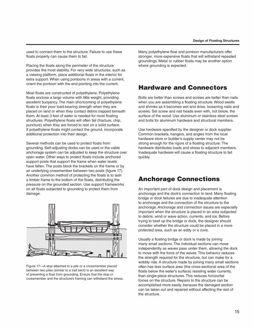
Figure 17—A stop attached to a pile or a crossmember placed between two piles (similar to a trail bent) is an excellent way of preventing a float from grounding. Ensure that the stop or crossmember and the structure’s framing can withstand the stress.
used to connect them to the structure. Failure to use these floats properly can cause them to fail.
Placing the floats along the perimeter of the structure provides the most stability. For very wide structures, such as a viewing platform, place additional floats in the interior for extra support. When using pontoons in areas with a current, orient the pontoon with the end pointing into the current.
Most floats are constructed of polyethylene. Polyethylene floats enclose a large volume with little weight, providing excellent buoyancy. The main shortcoming of polyethylene floats is their poor load-bearing strength when they are placed on land or when they contact debris trapped beneath them. At least 3 feet of water is needed for most floating structures. Polyethylene floats will often fail (fracture, chip, puncture) when they are forced to rest on a solid surface. If polyethylene floats might contact the ground, incorporate additional protection into their design.
Several methods can be used to protect floats from grounding. Self-adjusting docks can be used or the cable anchorage system can be adjusted to keep the structure over open water. Other ways to protect floats include anchored support posts that support the frame when water levels have fallen. The posts block the brackets on the frame or by an underlying crossmember between two posts (figure 17). Another common method of protecting the floats is to lash a timber frame to the bottom of the floats, distributing the pressure on the grounded section. Use support frameworks on all floats subjected to grounding to protect them from damage.
Many polyethylene float and pontoon manufacturers offer stronger, more expensive floats that will withstand repeated groundings. Metal or rubber floats may be another option where grounding is expected.
Hardware and ConnectorsBolts are better than screws and screws are better than nails when you are assembling a floating structure. Wood swells and shrinks as it becomes wet and dries, loosening nails and screws. Set screw and nail heads even with, not below, the surface of the wood. Use aluminum or stainless steel screws and bolts for aluminum hardware and structural members.
Use hardware specified by the designer or dock supplier. Common brackets, hangers, and angles from the local hardware store or builder’s supply center may not be strong enough for the rigors of a floating structure. The hardware distributes loads and stress to adjacent members. Inadequate hardware will cause a floating structure to fail quickly.
Anchorage ConnectionsAn important part of dock design and placement is anchorage and the dock’s connection to land. Many floating bridge or dock failures are due to inadequate attention to anchorage and the connection of the structure to the anchorage. Anchorage and connection issues are especially important when the structure is placed in an area subjected to debris, wind or wave action, currents, and ice. Before trying to beef up the bridge or dock, the designer should consider whether the structure could be placed in a more protected area, such as an eddy or a cove.
Usually a floating bridge or dock is made by joining many small sections. The individual sections can move independently as waves pass under them, allowing the dock to move with the force of the waves. This behavior reduces the strength required for the structure, but can make for a wobbly ride. A structure made by joining many small sections often has less surface area (the cross-sectional area of the floats below the water’s surface) resisting water currents, than single-piece structures. This reduces horizontal forces on the structure. Repairs to the structure can be accomplished more easily, because the damaged section can be taken out and repaired without affecting the rest of the structure.
16
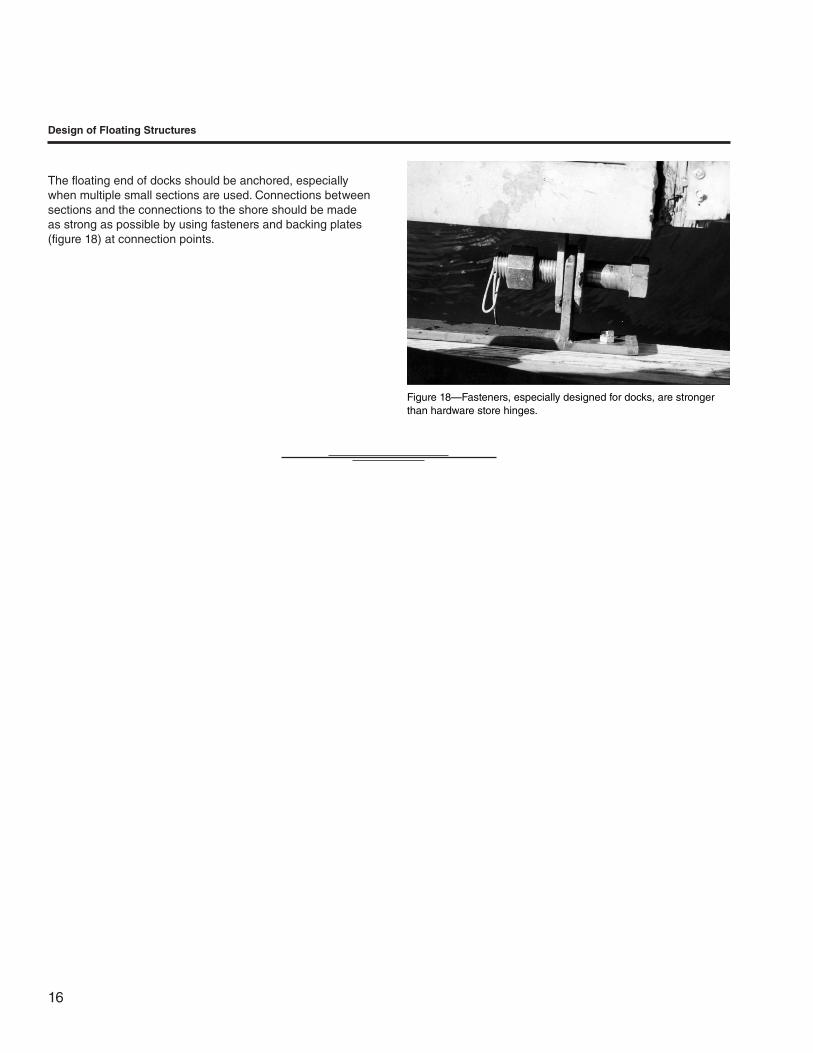
The floating end of docks should be anchored, especially when multiple small sections are used. Connections between sections and the connections to the shore should be made as strong as possible by using fasteners and backing plates (figure 18) at connection points.
Figure 18—Fasteners, especially designed for docks, are stronger than hardware store hinges.
Design of Floating Structures

17
TT he military has traditionally used cable anchorage systems for floating bridges that cross rivers. Only the most basic principles are covered here. Refer
to chapter 8 of Military Float Bridging Equipment for more information. The Web address for that report is listed in the Additional Information section. The main disadvantage of a cable anchorage system is that cables typically need to be adjusted seasonally or more frequently, especially in areas with fluctuating water levels. In addition to the military designs, we have included typical dock and boardwalk anchorage systems suitable for Forest Service applications.
Submerged Anchor Cable SystemsBy far the most common anchorage system is an anchor cable combination. The total weight of the anchorage should be at least twice the weight of the structure being anchored. It is better if the weight of the anchorage is three times (even more when conditions are severe) that of the structure being anchored. Many small anchors will grip the bottom better and can be more easily adjusted than a few large anchors. The anchor line is referred to as the rode. The length of the rode
Anchorage System Design
Rode
Figure 19—Proper layout of a submerged anchor cable system.
is called its scope. Concrete blocks are the most commonly used anchor (do not use common concrete masonry bricks or cinderblocks). Anchor connections are spaced along the length of the floating bridge with more connections in areas subjected to higher stresses, such as section and shoreline connections. An anchor with a connecting rode is dropped off the side at each connection.
Anchors have the most holding power when the angle from the anchor to its attachment point is 45 degrees. Cross-chaining the anchors (attaching the rode to one side of the frame and placing the anchor on the opposite side) provides additional holding power. Rodes should not be under tension. They should provide enough scope so that the cable curves from the anchor to the bridge (figure 19). The curve allows for minor water level changes and bridge movement. Docks should have at least two (one on each side) anchors at the end. Docks exposed to severe weather should have a storm anchor placed in the direction of the prevailing winds with the rode attached to the dock’s end and under slight tension.
Submerged anchor cable systems are not suitable for areas with fluctuating water levels such as reservoirs and tidal areas. Areas with smooth bedrock bottoms and sensitive habitats where anchors may harm desired species are also unsuitable.

18
Figure 20—Running cables—or approach guys—from shore to shore along a floating bridge provides an excellent means of anchorage.
Shoreline Anchor Cable SystemsMilitary floating bridges use a combination of submerged and shoreline anchors. Only a few of the more applicable types are covered here. Approach guys, also known as tension cables, connect the first section of the bridge to the shoreline. Cables run from the opposite corners of each section, preferably at a 45-degree angle, to shoreline anchorage points. If the bridge includes a ramp, these cables would crisscross under the ramp. They hold the bridge against the shoreline and reduce stress on the shoreline hinges or connectors. Tension cables allow for vertical movement and should have turnbuckles so they can be adjusted easily. Very often these cables run the entire length of the bridge to the opposite shoreline and function as the approach guys on both sides (figure 20). The advantage to this system is the tremendous lateral resistance it provides. However, if a section of the bridge needs to be removed the entire cable may need to be removed.
Shore guys are similar to approach guys. The attachment points are farther out on the bridge and farther away along the shoreline. A 45-degree angle provides the most holding
power. Longer shore guys will need flotation along their length to keep the cable or chain above the waterline. A qualified engineer should design approach and shore cable systems that will be under tension often.
Various methods exist for shoreline anchorage. Cribs, retaining walls, and solid structures work well. Holdfasts (natural anchorages such as boulders) also provide adequate holding power. Various types of deadmen (anchors buried on shore) or pickets driven into the ground at least 15 degrees away from the direction of pull will serve as anchors. Be sure that anchorage points will hold during severe conditions and that the design does not invite vandalism.
Anchorage System Design
Cablebracket
Concretelanding
Cable
Cableclamp
U-boltembeddedin concrete
Cable

19
Figure 21—Basic parts of an overhead cable anchorage system.
Overhead Anchor Cable SystemsThis military design may fit some Forest Service applications. Overhead anchor cable systems share features with conventional suspended trail bridges. A cable anchored on both shorelines is run over towers. The towers provide elevation. The elevated anchor cable runs parallel to the floating bridge and is upstream of it. Additional cables, called bridle lines, run from the anchor cable to attachment points on the floating bridge. The overhead cable system helps keep the bridge in position (figure 21), but does not provide lift.
Pile AnchoragesPiles function as many different types of anchors. They can be substituted for submerged anchors. Drive piles close to the floating bridge, then hook the bridge to the pile for anchorage. Place hooks at different heights, have different lengths of cable, or include a turnbuckle on the cable so the bridge’s position can be adjusted for different water levels.
Pile holders can be used to attach the bridge to the piles. External pile holders typically are a hoop or square that surrounds the pile with a solid bracket attached to the edge of the frame (figure 22). Square holders usually have bearings to reduce wear. A simple chain also will work,
Anchorage System Design
Additional anchorage
Anchor cable
Deadman
Bridle lines
Cable tower

20
Figure 22—This dock uses multiple external pile holders for anchorage (photo by Paul Schrooten, USDI Fish and Wildlife Service).
Figure 23—A sleeved pile should have a stop on the exterior of the inside pile or on the interior of the outer pile to keep the outer pile at the desired level.
but the chain may increase wear on the pile. Internal pile holders are also available for piles that are placed inside the perimeter of the bridge. A pile system will reduce twisting forces on the shore connections and on the connections between sections of the floating structure. Piles are an excellent means of support for structures in areas where water levels fluctuate because they allow vertical movement while still providing anchorage. Their shortcoming is that they restrict horizontal movement. This may result in sections close to shore becoming grounded during periods of low water. The structure may be isolated during high water, making it inaccessible. These issues can be addressed by designing the shore access to accommodate changing water levels.
A variety of piles are available. Wood is the most common. Oil-based preservative treatments tend to perform better than water-based treatments when piles are submerged. Some municipalities require both types of treatment for piles used in saltwater areas. Oil-based treatments are not recommended for materials humans will contact and in certain environmental settings (usually very slow flow conditions). Decisions about which type of preservative to use need to be made on a case-by-case basis. Refer to the Additional Information section for more details.
Corrosion-resistant steel piles or concrete piles are also an option for pile anchors. Helical screws are also available. Helical screws are screwed into the ground using equipment that is small and portable.
Piles are set using three common methods. Piles can be driven using a pile-driving hammer, jetted into place by using a high-pressure stream of water to carve a hole, or grouted into holes that have been drilled, usually into bedrock.
Floating bridges and docks that use properly installed pilings and posts as anchors have an excellent chance of staying in place. The required depth and diameter of a pile depends on the size of the bridge and the forces acting on it.
Areas subject to heavy ice formation are vulnerable to pile failure. One national forest reported sinking piles 20 feet into the soil to support a boardwalk. During years of heavy ice formation, ice ripped the boardwalk and piling out of the ground. Tapered piles resist the upward pull of ice.
Another clever approach is to use a sleeved pile. First, set a traditional pile. Fit a hollow pile, with a bearing plate to hold the deck at its normal elevation above the water, over the first pile. As the ice pulls the deck up, the hollow pile will move up with the ice and drop back down as the ice melts (figure 23).
Anchorage System Design
Welded stop plate
21
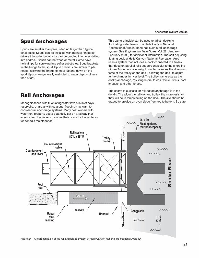
Spud AnchoragesSpuds are smaller than piles, often no larger than typical fenceposts. Spuds can be installed with manual fencepost drivers into softer bottoms or can be grouted into holes drilled into bedrock. Spuds can be wood or metal. Some have helical tips for screwing into softer substrates. Spud brackets tie the bridge to the spud. Spud brackets are similar to pile hoops, allowing the bridge to move up and down on the spud. Spuds are generally restricted to water depths of less than 5 feet.
Rail AnchoragesManagers faced with fluctuating water levels in inlet bays, reservoirs, or areas with seasonal flooding may want to consider rail anchorage systems. Many boat owners with waterfront property use a boat dolly set on a railway that extends into the water to remove their boats for the winter or for periodic maintenance.
Anchorage System Design
This same principle can be used to adjust docks to fluctuating water levels. The Hells Canyon National Recreational Area in Idaho has such a rail anchorage system. See Engineering Field Notes, Vol. 22, January-February (1990) for additional information. The self-adjusting floating dock at Hells Canyon National Recreation Area uses a system that includes a dock connected to a trolley that rides on parallel rails set perpendicular to the shoreline (figure 24). A concrete weight counterbalances the downward force of the trolley on the dock, allowing the dock to adjust to the changes in river level. The trolley frame acts as the dock’s anchorage, resisting lateral forces from currents, boat impacts, and other forces.
The secret to success for rail-based anchorage is in the details. The wider the railway and trolley, the more resistant they will be to forces acting on the dock. The site should be graded to provide an even slope from top to bottom. Be sure
Figure 24—A representation of the rail anchorage system at Hells Canyon National Recreational Area, ID.
Counterweightcable
Counterweightand tower
Foottrail
Upperstair
landing
StairwayHandrail
Trolleyframe
Rail system80' L x 19' W
26' x 30' Floating dock,four-boat capacity
Gangplank
Eb
bfl
ow
Sn
ake R
iver
Sh
ore
lin
eS
ho
reli
ne
22
Anchorage System Design
not to create a runoff path that could erode the support for the railway. The track also should be level from side to side. A concrete ramp, timber ties, or similar supports can be used to level the gradient. The rails themselves should be pinned, bolted, welded or somehow anchored so they do not shift. Backfilling the rails with gravel or rock once the railway is set provides even more holding power. Cross brace and diagonally brace the main steel beams of the frame.
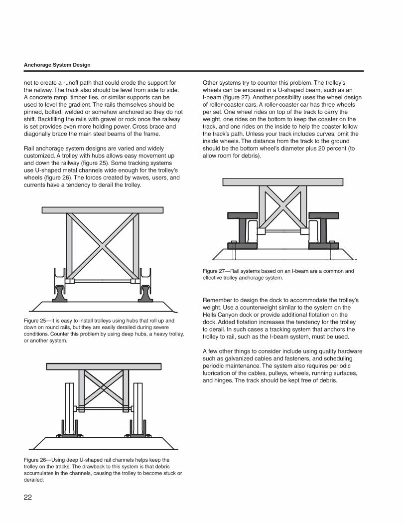
Rail anchorage system designs are varied and widely customized. A trolley with hubs allows easy movement up and down the railway (figure 25). Some tracking systems use U-shaped metal channels wide enough for the trolley’s wheels (figure 26). The forces created by waves, users, and currents have a tendency to derail the trolley.
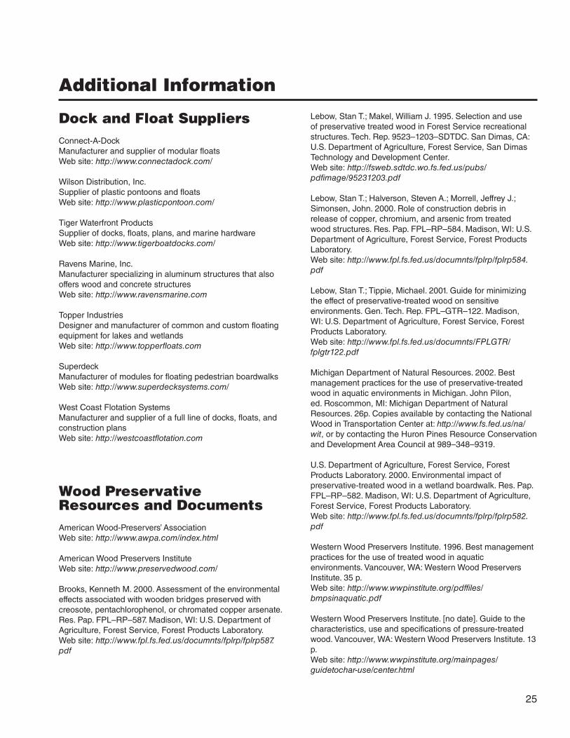
Other systems try to counter this problem. The trolley’s wheels can be encased in a U-shaped beam, such as an I-beam (figure 27). Another possibility uses the wheel design of roller-coaster cars. A roller-coaster car has three wheels per set. One wheel rides on top of the track to carry the weight, one rides on the bottom to keep the coaster on the track, and one rides on the inside to help the coaster follow the track’s path. Unless your track includes curves, omit the inside wheels. The distance from the track to the ground should be the bottom wheel’s diameter plus 20 percent (to allow room for debris).
Figure 25—It is easy to install trolleys using hubs that roll up and down on round rails, but they are easily derailed during severe conditions. Counter this problem by using deep hubs, a heavy trolley, or another system.
Figure 26—Using deep U-shaped rail channels helps keep the trolley on the tracks. The drawback to this system is that debris accumulates in the channels, causing the trolley to become stuck or derailed.
Remember to design the dock to accommodate the trolley’s weight. Use a counterweight similar to the system on the Hells Canyon dock or provide additional flotation on the dock. Added flotation increases the tendency for the trolley to derail. In such cases a tracking system that anchors the trolley to rail, such as the I-beam system, must be used.
A few other things to consider include using quality hardware such as galvanized cables and fasteners, and scheduling periodic maintenance. The system also requires periodic lubrication of the cables, pulleys, wheels, running surfaces, and hinges. The track should be kept free of debris.
Figure 27—Rail systems based on an I-beam are a common and effective trolley anchorage system.
23
TShore Anchorage and Access
T he means of getting from the shore to the floating structure depends on the site. The shoreline access structure often provides additional anchorage or
may provide all of the anchorage. When the shoreline access also provides shoreline anchorage, the connection must be strong enough for both purposes.
Shoreline AccessWhen shoreline anchorage is provided by some means other than the access structure, access is quite simple. Gangways or ramps are the traditional means of access. They allow for moderate water level changes without adjustment. One end of the ramp is on the shoreline and the other is on the bridge or dock. Additional floats may be needed where the ramp joins the floating structure, either on the structure itself or on the ramp if it contacts the water. Sometimes the ramp will need to be connected, usually with hinges, to a landing platform on the shoreline. Ramps may also be hinged to the bridge or dock. Hinging the ramp to the shoreline and structure will provide additional anchorage. Ramps can be mounted on rollers on the end of the structure. This creates a step that may prevent the structure from meeting accessibility standards for persons who are physically challenged. Provide traction on the ramp by placing cleats at 1- to 2-foot intervals (accessibility issues are a concern) or by using metal perforated floors, plastic traction mats, a traction coating, or some other method. In general, the ramp should be as wide as the structure, both for user comfort and to help relieve stress on the hinges, when applicable.
In areas with fluctuating water levels, ramps should be installed so that the ramp is level with the dock during high water.
The ramp angle should never exceed 30 degrees (67- percent slope). An angle of 20 degrees (44-percent slope) is too extreme for some users. The maximum slope of a ramp should be 1:12 or less (8.33 percent) to meet accessibility guidelines. Consult with accessibility interest groups if your structure will be located in an accessible setting. Several ways to decrease the ramp’s angle include lowering the mounting point at the shoreline, raising the mounting point on the bridge, and increasing the length of the ramp.
Shoreline AnchorageOften the shoreline anchorage provides most if not all the anchorage for the floating structure. The forces on the anchorage can be very large. The dock acts as a lever. The force of an impact at the end of a dock can be multiplied many times when it acts on the shoreline anchorage.
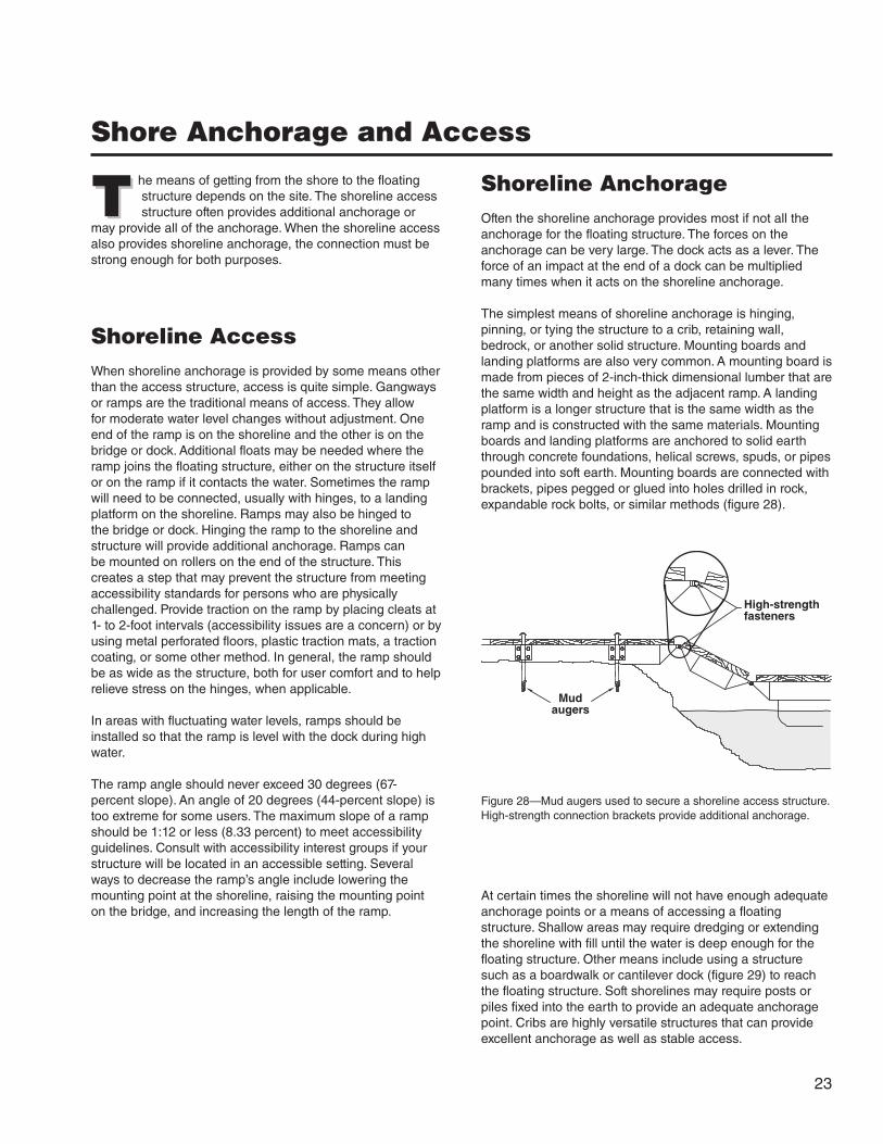
The simplest means of shoreline anchorage is hinging, pinning, or tying the structure to a crib, retaining wall, bedrock, or another solid structure. Mounting boards and landing platforms are also very common. A mounting board is made from pieces of 2-inch-thick dimensional lumber that are the same width and height as the adjacent ramp. A landing platform is a longer structure that is the same width as the ramp and is constructed with the same materials. Mounting boards and landing platforms are anchored to solid earth through concrete foundations, helical screws, spuds, or pipes pounded into soft earth. Mounting boards are connected with brackets, pipes pegged or glued into holes drilled in rock, expandable rock bolts, or similar methods (figure 28).
Figure 28—Mud augers used to secure a shoreline access structure. High-strength connection brackets provide additional anchorage.
At certain times the shoreline will not have enough adequate anchorage points or a means of accessing a floating structure. Shallow areas may require dredging or extending the shoreline with fill until the water is deep enough for the floating structure. Other means include using a structure such as a boardwalk or cantilever dock (figure 29) to reach the floating structure. Soft shorelines may require posts or piles fixed into the earth to provide an adequate anchorage point. Cribs are highly versatile structures that can provide excellent anchorage as well as stable access.
High-strengthfasteners
Mudaugers

24
Existing retaining wall
8" x 8" x 10' Mud sill, treated
Johnson Lake
Edge of wetlands
New retaining wall
4" x 4" Curbing
Edge of wetlandsFill
Scale: 1"= 20'
Access trailSteep bedrock hill
A
C
E
B
B
D2
D2
C
C
C
A= 8' x 10' RampB= 8' x 10' Boardwalk sectionC= 5' x 10' Section
D2= 5' x 15' Floating sectionE= 6' x 6' Filler
D1
D1
D1
D1
F2
F1= 6' x 10' Section
C
C
F1
G
G= 6' x 5' Hinged ramp section
4'
Bedro
ck 12'
12'
08/25/99
F2
4" x 4" Curbing
Hinged
Remove top 4' section
NOTE: Install inside metal cornerbrackets on all sections.
Hinged
D1= 5' x 15' Section
F2= 6' x 10' Floating section
17'
*
*
Johnson Lake Trail—Lake AccessBoardwalk and Floating Dock Structure
Figure 29—The drawing of the dock system on the cover shows how a boardwalk is used to cross a wetland to open water. Other methods could also have been used, depending on the site’s conditions.
Shore Anchorage and Access
25
Additional Information
Dock and Float SuppliersConnect-A-DockManufacturer and supplier of modular floatsWeb site: http://www.connectadock.com/
Wilson Distribution, Inc.Supplier of plastic pontoons and floatsWeb site: http://www.plasticpontoon.com/
Tiger Waterfront ProductsSupplier of docks, floats, plans, and marine hardwareWeb site: http://www.tigerboatdocks.com/
Ravens Marine, Inc.Manufacturer specializing in aluminum structures that also offers wood and concrete structuresWeb site: http://www.ravensmarine.com
Topper IndustriesDesigner and manufacturer of common and custom floating equipment for lakes and wetlandsWeb site: http://www.topperfloats.com
SuperdeckManufacturer of modules for floating pedestrian boardwalksWeb site: http://www.superdecksystems.com/
West Coast Flotation SystemsManufacturer and supplier of a full line of docks, floats, and construction plansWeb site: http://westcoastflotation.com
Wood Preservative Resources and DocumentsAmerican Wood-Preservers’ AssociationWeb site: http://www.awpa.com/index.html
American Wood Preservers InstituteWeb site: http://www.preservedwood.com/
Brooks, Kenneth M. 2000. Assessment of the environmental effects associated with wooden bridges preserved with creosote, pentachlorophenol, or chromated copper arsenate. Res. Pap. FPL–RP–587. Madison, WI: U.S. Department of Agriculture, Forest Service, Forest Products Laboratory.Web site: http://www.fpl.fs.fed.us/documnts/fplrp/fplrp587.pdf
Lebow, Stan T.; Makel, William J. 1995. Selection and use of preservative treated wood in Forest Service recreational structures. Tech. Rep. 9523–1203–SDTDC. San Dimas, CA: U.S. Department of Agriculture, Forest Service, San Dimas Technology and Development Center.Web site: http://fsweb.sdtdc.wo.fs.fed.us/pubs/pdfimage/95231203.pdf
Lebow, Stan T.; Halverson, Steven A.; Morrell, Jeffrey J.; Simonsen, John. 2000. Role of construction debris in release of copper, chromium, and arsenic from treated wood structures. Res. Pap. FPL–RP–584. Madison, WI: U.S. Department of Agriculture, Forest Service, Forest Products Laboratory.Web site: http://www.fpl.fs.fed.us/documnts/fplrp/fplrp584.pdf
Lebow, Stan T.; Tippie, Michael. 2001. Guide for minimizing the effect of preservative-treated wood on sensitive environments. Gen. Tech. Rep. FPL–GTR–122. Madison, WI: U.S. Department of Agriculture, Forest Service, Forest Products Laboratory.Web site: http://www.fpl.fs.fed.us/documnts/FPLGTR/fplgtr122.pdf
Michigan Department of Natural Resources. 2002. Best management practices for the use of preservative-treated wood in aquatic environments in Michigan. John Pilon, ed. Roscommon, MI: Michigan Department of Natural Resources. 26p. Copies available by contacting the National Wood in Transportation Center at: http://www.fs.fed.us/na/wit, or by contacting the Huron Pines Resource Conservation and Development Area Council at 989–348–9319.
U.S. Department of Agriculture, Forest Service, Forest Products Laboratory. 2000. Environmental impact of preservative-treated wood in a wetland boardwalk. Res. Pap. FPL–RP–582. Madison, WI: U.S. Department of Agriculture, Forest Service, Forest Products Laboratory.Web site: http://www.fpl.fs.fed.us/documnts/fplrp/fplrp582.pdf
Western Wood Preservers Institute. 1996. Best management practices for the use of treated wood in aquatic environments. Vancouver, WA: Western Wood Preservers Institute. 35 p.Web site: http://www.wwpinstitute.org/pdffiles/bmpsinaquatic.pdf
Western Wood Preservers Institute. [no date]. Guide to the characteristics, use and specifications of pressure-treated wood. Vancouver, WA: Western Wood Preservers Institute. 13 p.Web site: http://www.wwpinstitute.org/mainpages/guidetochar-use/center.html

26
Pontoons and Metal FloatsAmerican Pontoon BoatsWeb site: http://www.americanboat.com/
Shoco Marine, Inc.Web site: http://www.shocomarine.com
Military DocumentsMilitary float bridging equipment. TC 5–210. 1988. Washington, DC: Department of the Army.Web site: http://www.adtdl.army.mil/cgi-bin/atdl.dll/tc/5-210/toc.htm
Pile construction. FM 5–134. 1985. Washington, DC: Department of the Army.Web site: http://www.adtdl.army.mil/cgi-bin/atdl.dll/fm/5-134/toc.htm
Bailey Bridge. FM 5–277. 1986. Washington, DC: Department of the Army.[Note: The two chapters that are of the most interest to Forest Service users are chapter 16, Bridges on Piers, and chapter 20, Bridges on Barges.]Web site: http://www.adtdl.army.mil/cgi-bin/atdl.dll/fm/5-277/toc.htm
River-crossing operations. FM 90–13. 1998. Washington, DC: Department of the Army, Commandant, U.S. Marine Corps.Web site: http://www.adtdl.army.mil/cgi-bin/atdl.dll/fm/90-13/tocfin.htm
ReferencesBurns, Max. The dock manual. 1999. Pownal, VT: Storey Books. 201 p.
Eriksson, Merv. 2002. Trail bridge catalog. [Available to Forest Service and Bureau of Land Management employees on their internal network at: http:// fsweb.mtdc.wo.fs.fed.us/bridges/] [Available to the public at http://www.fhwa.dot.gov/environment/trailpub.htm]
Hesselbarth, Woody; Vachowski, Brian. 1996 (rev. 2000). Trail construction and maintenance notebook. 0023–2839–MTDC. Missoula, MT: U.S. Department of Agriculture, Forest Service, Missoula Technology and Development Center. 139 p. [Call 406–329–3978 for a printed copy.]
Mahugh, Irvin G. 1990. Hells Canyon boat dock on the Snake River. Engineering Field Notes. 22 (January-February): 33-34. Washington DC: U.S. Department of Agriculture, Forest Service. [Available to Forest Service and Bureau of Land Management employees on their internal network at: http://fsweb.wo.fs.fed.us/eng/pubs/efn/efn-cont.htm]
Mason, Lola. 1990. Portable wetland area and stream crossings. 9024–1203–SDTDC. San Dimas, CA: U.S. Department of Agriculture, Forest Service, San Dimas Technology and Development Center. 110 p. [Call 909–599–1267, ext. 201 for a printed copy. Available to Forest Service and Bureau of Land Management employees on their internal network at: http://fsweb.sdtdc.wo.fs.fed.us/pubs/pdfimage/90241203.pdf]
Steinholtz, Robert T.; Vachowski, Brian. 2001. Wetland trail design and construction. Tech. Rep. 0123–2833–MTDC. Missoula, MT: U.S. Department of Agriculture, Forest Service, Missoula Technology and Development Center. 83 p. [Call 406–329–3978 for a printed copy. Available to Forest Service and Bureau of Land Management employees on their internal network at: http://fsweb.mtdc.wo.fs.fed.us/pubs/lc/lc01232833.htm]
Streeper, Richard J. 1990. Designed natural-appearing cement structures for wet area enhancement. Engineering Field Notes. 22 (July-August): 15-22. U.S. Department of Agriculture, Forest Service. [Available to Forest Service and Bureau of Land Management employees on their internal network at: http://fsweb.wo.fs.fed.us/eng/pubs/efn/efn-cont.htm]
Additional Information

Library CardNeese, Jasen; Eriksson, Merv; Vachowski, Brian. 2002. Floating trail bridges and docks. Tech. Rep. 0223–2812P–MTDC. Missoula, MT: U.S. Department of Agriculture, Forest Service, Missoula Technology and Development Center. 26 p.
Describes the use of floating bridges and docks for Forest Service recreational trails. The report includes information about floating boat docks, floating bridge designs, anchorage systems, and devices that allow the dock to adjust itself to varying water levels. Floating bridges should generally be a structure of last resort, used only for crossing ponds, marshes, swamps, bogs, or similar areas that are too wet for more traditional, less costly trail bridges, or for other wetland trail construction techniques. Floating trail bridges can provide a viable, but limited, alternative to the traditional means of crossing wet areas.
Keywords: Anchorages, anchors, boardwalks, bogs, bridges, cable anchorages, cribs, decks, docks, drainage, flotation, marshes, piers, piles, rails, railway, trail bridges, trails, Styrofoam, swamps, wet areas, wetlands, wood preservatives
About the AuthorsJasen Neese worked as an intern at MTDC while studying for a bachelor’s degree in natural resource conservation at the University of Montana. He has worked on projects including lead-based paint mitigation, energy conservation, and hazardous material regulation compliance. After receiving his degree in 2001, Neese has continued working for MTDC as a freelance project associate.
Merv Eriksson has a bachelor’s degree in civil engineering from the University of North Dakota. He worked as a highway and bridge engineer with the Federal Highway Administration before joining the Forest Service’s Northern Region in 1979 as a structural engineer. He was leader of the Northern Region Bridge Design and Construction Group from 1986 until 1997 when he joined MTDC. While at MTDC, Eriksson acted as the technical coordinator for the Wood in Transportation program and managed a number of
projects for the Forest Service Technology and Development Centers, and the Forest Products Laboratory. Merv is now the Pacific Northwest Forest Service regional bridge engineer in Portland, OR.
Brian Vachowski has been a project leader specializing in recreation, trails, and wilderness projects at MTDC since 1993. He received a bachelor’s of science degree in forestry from the University of Massachusetts and a master’s of science degree in outdoor recreation from Utah State University. He has worked for the Nez Perce, Bighorn, Winema, and Routt National Forests in recreation, wilderness, lands, planning, rural community assistance, special uses, fire, and timber positions. Before coming to MTDC he was an assistant staff officer for wilderness and recreation on the Nez Perce National Forest.
You can order a copy of this document using the order form on the FHWA’s Recreational Trails Program Web site at: http://www.fhwa.dot.gov/environment/trailpub.htmElectronic copies may also be available at this site.
Fill out the order form and fax it to the distributor listed on the form. If you do not have Internet access, you can send a fax request to 202–366–3409 or a mail request to: USDOT, Federal Highway Administration Office of Human Environment, Room 3301 400 7th St. SW. Washington, DC 20590
Forest Service and Bureau of Land Management employees may obtain additional copies from: USDA FS, Missoula Technology and Development Center 5785 Hwy. 10 West Missoula, MT 59808-9361 Phone: 406–329–3978 Fax: 406–329–3719 E-mail: [email protected]
Electronic copies of MTDC’s documents are available to Forest Service and BLM employees on the Forest Service’s FSWeb Intranet at: http://fsweb.mtdc.wo.fs.fed.us
For further technical information, contact Brian Vachowski at MTDC.
Brian Vachowski: Phone: 406–329–3935 Fax: 406–329–3719 Lotus Notes: Brian J Vachowski/WO/USDAFS E-mail: [email protected]