flight path pid controller for propeller-driven fixed ...repository.um.edu.my/31344/1/flight path...
TRANSCRIPT

International Journal of the Physical Sciences Vol. 6(8), pp. 1947-1964, 18 April, 2011 Available online at http://www.academicjournals.org/IJPS ISSN 1992 – 1950 ©2011 Academic Journals Full Length Research Paper
Flight path PID controller for propeller-driven fixed-wing unmanned aerial vehicles
B. M. Albaker* and N. A. Rahim
UMPEDAC Research Centre, Malaya University, Kuala Lumpur, Malaysia.
Accepted 22 March, 2011
The world of the future will be filled with intelligent unmanned aircraft employed to autonomously perform tasks and substituting human efforts in applications where human operation is dangerous, inefficient and/or impossible. Towards this goal, an autonomous flight path state holding for a fixed-wing propeller-driven unmanned aircraft is developed. The development is based on the utilization of a “proportional-integral-derivative” control loops structure. The proposed control loops are turn and turn-rate, airspeed and altitude states holding. The control structure provides a low level control necessarily for mission planning and execution. Details about the UAV dynamics and “propeller-driven modeling” are provided. The control algorithm generates the control law for a UAV while explicitly dealing with their multi-input multi-output non-linear dynamics, input saturation and state constraints. The UAV dynamics response together with controller closed loop response is then presented. Simulations were performed to test the performance of the proposed system and the aircraft succeeded in following the desired states. Simulation results show that the proposed controller can be effectively used for holding desired states of a UAV’s commanded path. Key words: Unmanned aerial vehicle, flight path controller, control and autonomous flight, proportional-integral-derivative.
INTRODUCTION Today, UAVs bring unquestioned list of capabilities and increasing array of critical tasks for military and civil applications. Because of its key characteristics, UAVs are useful for reconnaissance, remote delivery, resource assessment, observing and planning rescue activities in dangerous areas, surveillance, environment monitoring, battlefield monitoring, etc., making it attractive attributes in the near future. These applications are well covered in (DoD, 2010). Recently, there has been a great interest in the development of advanced unmanned aircraft capable of executing missions in complex dynamic environments. Deployment of intelligent UAVs has been made possible through technological advances. Advanced flight control systems for urban navigation should be able to adjust the flight path dynamically with the information on the sur-roundings. These topics have been intensively covered by the robotics community since the late 1970s. Based on these efforts, various algorithms and implementations *Corresponding author. E-mail: [email protected].
are currently available. A flight path control system is designed to manage, command and regulate the UAV dynamic model. The goal is to make a system behave in a desired way and at a desired performance. According to Bekey (2005), “autonomy” refers to systems capable of operating in the real-world environment without any form of external control for extended periods of time. Several software systems and methods that could be used for controlling autonomous vehicles are recently reviewed (Long et al., 2007; Chao et al., 2007). Due to high nonlinearities of the aircraft dynamics, a lot of intelligent control techniques have been used for flight path controller.
Airplanes boast a long history of automatic control and many of these control techniques were applied to autonomous UAVs. Most of the commercial flight path controllers utilized the PID loops structure. The reason behind this is partly because they are effective and partly because they are straightforward to design and implement on aircraft platforms. Researches on flight path controllers for UAVs are also quite active with a lot of modern control strategies used. Several approaches

1948 Int. J. Phys. Sci. have instituted various robust control methods, such as the linear quadratic Gaussian, H�, gain scheduling, sliding mode control, etc. (Hess, 1995; Kaminer et al., 1995, 1998; Chu et al., 1996; Shtessel et al., 1998; Khammash and Zou, 1999; Andrievsky and Fradkov, 2003; Sadraey and Colgren, 2005; Santoso et al., 2007). Fuzzy logic control systems can be used in many applications including flight path controlling (Sugeno et al., 1995; Fernandez et al., 1999; Vascak et al., 2001; Kumon et al., 2006). Adaptive neural network controller can also be used; however it does not require an accurate mathematical model and it is suitable for multi-variable flight control (Johnson and Kannan, 2002; Christophersen et al., 2006; Muse et al., 2009). A variety of UAV structures have also been studied. The size and weight of UAVs are also important factors. Fixed-wing UAVs and Helicopters have been extensively examined in spite of the complex dynamics (Koo and Sastry, 1998; Shim et al., 1998; Montogomery and Bekey, 1998; Albaker and Rahim, 2010, 2011). Grasmeyer and Keennon (1998), Lyshevsk (2001) and Wu et al. (2004) developed a micro aerial vehicle (MAV). Schenato et al. (2003) and Rifai et al. (2009) conducted their research on flapping MAV inspired from natural flight.
Several flight controller products are already comer-cially available. Although, these products enable the user to execute several tasks, such as autonomous flight control, guidance, waypoint navigation, etc, however, they provide limited access to the internal control structures. Therefore, they are most appropriate for higher-levels control tasks. In order to provide maximum flexibility in control of law development and implement-tation, the flight path controller is designed and tested. This paper presents the synthesis of a flight path PID control system for fixed-wing propeller-driven UAVs that endow UAVs with autonomy to independently respond to the desired aircraft states and accessibility by higher-levels control layers if necessary so that they can employ in a versatile, resilient and decentralized system. The remaining part of this paper is organized as follows:
First is an introduction of the UAV dynamics including the propeller driven model. Next is a presentation of the aircraft open-loop dynamics simulation before applying the proposed PID controller. This is then followed by an illustration of the design models carried out for the states holding control system. Three sub-models are developed including turn and turn rate, velocity and altitude hold controllers. The proposed PID controller is then applied to UAV dynamics in a closed-loop, after which simulation results are demonstrated. Concluding remarks are thereafter presented. UNMANNED AIRCRAFT MOTION EQUATIONS Although the complete dynamics of a fixed-wing UAV are complex, a point mass rigid body three degree of
freedom (3DOF) model can provide useful information. It is necessary to categorize the dynamics of a UAV before designing the controller. Let the velocity frame be a Cartesian coordinate system that is attached to the aircraft with the origin located at the center of gravity. The X-axis is aligned with the velocity vector and the Z-axis is oriented downward, goes through the bottom of aircraft. The Y-axis goes through the right side wing and it is defined using a right-hand coordinate system. The velocity vector frame is referenced to the body frame through angle of attach (AoA) and bank angle (�). Let the local frame be a Cartesian coordinate system that is fixed to the ground. The PN-axis and the PE-axis of the local frame are aligned to the north and the east, respectively. The PD-axis is the perpendicular direction oriented down-ward. The velocity of the airplane is denoted as V. The point-mass 3DOF equations of motion are derived with respect to north, east and down (NED) local coordinate system from (Zipfel, 2007).
The aircraft’s velocity response to thrust is also modeled. Using the defined notation, the dynamics of the 3DOF aircraft can be written as follows:
(1)
(2)
(3)
(4)
(5)
(6)
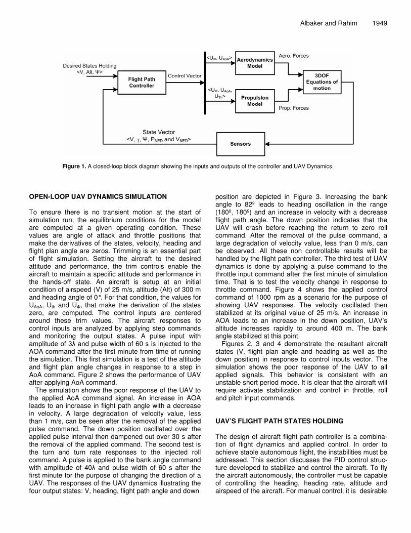
The simulation utilizes standard 3DOF equations of motion where g and m are the gravitational acceleration and aircraft mass respectively. The input control commands are AoA command (UAoA), throttle command (Uth) and the bank angle command (U�). The velocity, flight path angle (�), heading (�), and “north, east and down velocities” and “positions” (VNED, PNED) are the state variables (x). u = [uAoA, uth, u�] 3; x = {x 9| x=(V, � ,� ,VN, VE, VD ,PN, PE, PD) } (7) The dynamic characteristics of interest are the aircraft’s response to step inputs. To understand the response of the aircraft, a model is imported into a simulation environment constructed in Matlab/Simulink. The block diagram of the UAV dynamic model together with the proposed controller is shown in Figure 1.
Albaker and Rahim 1949
Figure 1. A closed-loop block diagram showing the inputs and outputs of the controller and UAV Dynamics.
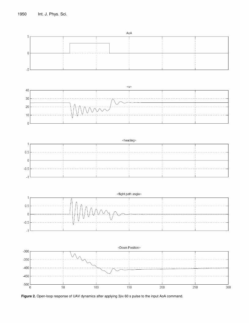
OPEN-LOOP UAV DYNAMICS SIMULATION To ensure there is no transient motion at the start of simulation run, the equilibrium conditions for the model are computed at a given operating condition. These values are angle of attack and throttle positions that make the derivatives of the states, velocity, heading and flight plan angle are zeros. Trimming is an essential part of flight simulation. Setting the aircraft to the desired attitude and performance, the trim controls enable the aircraft to maintain a specific attitude and performance in the hands-off state. An aircraft is setup at an initial condition of airspeed (V) of 25 m/s, altitude (Alt) of 300 m and heading angle of 0°. For that condition, the values for UAoA, Uth and U�, that make the derivation of the states zero, are computed. The control inputs are centered around these trim values. The aircraft responses to control inputs are analyzed by applying step commands and monitoring the output states. A pulse input with amplitude of 3� and pulse width of 60 s is injected to the AOA command after the first minute from time of running the simulation. This first simulation is a test of the altitude and flight plan angle changes in response to a step in AoA command. Figure 2 shows the performance of UAV after applying AoA command.
The simulation shows the poor response of the UAV to the applied AoA command signal. An increase in AOA leads to an increase in flight path angle with a decrease in velocity. A large degradation of velocity value, less than 1 m/s, can be seen after the removal of the applied pulse command. The down position oscillated over the applied pulse interval then dampened out over 30 s after the removal of the applied command. The second test is the turn and turn rate responses to the injected roll command. A pulse is applied to the bank angle command with amplitude of 40� and pulse width of 60 s after the first minute for the purpose of changing the direction of a UAV. The responses of the UAV dynamics illustrating the four output states: V, heading, flight path angle and down
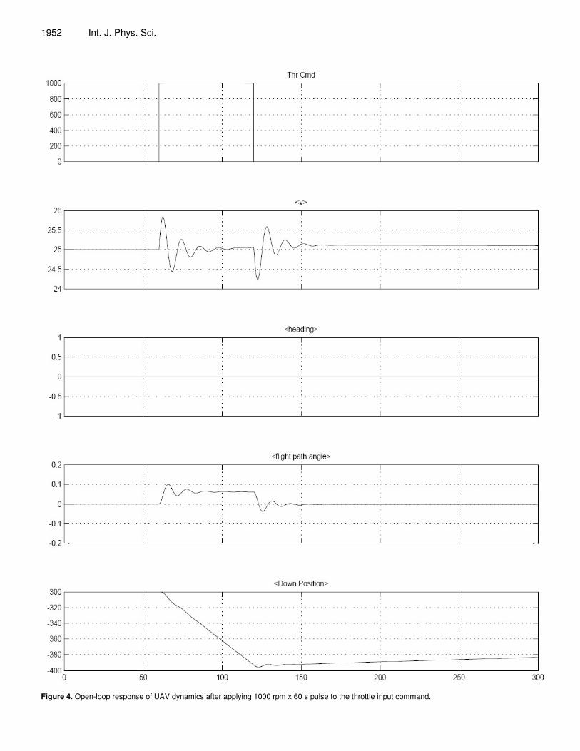
position are depicted in Figure 3. Increasing the bank angle to 82º leads to heading oscillation in the range (180º, 180º) and an increase in velocity with a decrease flight path angle. The down position indicates that the UAV will crash before reaching the return to zero roll command. After the removal of the pulse command, a large degradation of velocity value, less than 0 m/s, can be observed. All these non controllable results will be handled by the flight path controller. The third test of UAV dynamics is done by applying a pulse command to the throttle input command after the first minute of simulation time. That is to test the velocity change in response to throttle command. Figure 4 shows the applied control command of 1000 rpm as a scenario for the purpose of showing UAV responses. The velocity oscillated then stabilized at its original value of 25 m/s. An increase in AOA leads to an increase in the down position, UAV’s altitude increases rapidly to around 400 m. The bank angle stabilized at this point.
Figures 2, 3 and 4 demonstrate the resultant aircraft states (V, flight plan angle and heading as well as the down position) in response to control inputs vector. The simulation shows the poor response of the UAV to all applied signals. This behavior is consistent with an unstable short period mode. It is clear that the aircraft will require activate stabilization and control in throttle, roll and pitch input commands. UAV’S FLIGHT PATH STATES HOLDING The design of aircraft flight path controller is a combina-tion of flight dynamics and applied control. In order to achieve stable autonomous flight, the instabilities must be addressed. This section discusses the PID control struc-ture developed to stabilize and control the aircraft. To fly the aircraft autonomously, the controller must be capable of controlling the heading, heading rate, altitude and airspeed of the aircraft. For manual control, it is desirable
1950 Int. J. Phys. Sci.
Figure 2. Open-loop response of UAV dynamics after applying 3���x 60 s pulse to the input AoA command.

Albaker and Rahim 1951
Figure 3. Open-loop response of UAV dynamics after applying 82� x 60 s pulse to the bank angle input command.
1952 Int. J. Phys. Sci.
Figure 4. Open-loop response of UAV dynamics after applying 1000 rpm x 60 s pulse to the throttle input command.

Albaker and Rahim 1953
Figure 5. Simulink block diagram showing the inputs/outputs of the proposed flight path controller.
that the controller also accepts AOA, bank angle and throttle commands. To accomplish this goal, a controller constructed of nested PID loops has been developed. The airspeed is controlled through inner PID loop that stabilize the throttle, whereas the heading, heading rate and altitude are controlled with outer loops. Figure 5 shows the connections and inputs/outputs of the control loops which are explained in the following as follows: Turn and turn rate hold controller This controller generates the commands for the bank angle. The control loop is responsible for controlling the heading and heading rate of the aircraft, as shown in Figure 6. It generates a bank angle from the heading error if a “turn control” is activated. Otherwise if a turn rate command following is activated, the controller will generate a constant turn rate (TR) based on the Formula 8 given in Clancy (1975):
(8)
Given turn command (Tcmd), PID tuned values (KP, KI and KD), aircraft states and desired turn and turn rate values, the roll angle command law is computed by:
(9) Where Tt is the turn term that is equals to measured in
case if Tcmd = 1. Airspeed hold controller The control variable for speed is throttle. The purpose of

1954 Int. J. Phys. Sci.
Figure 6. Block diagram of the turn hold and turn rate controller.
this loop is to control the aircraft’s airspeed by adjusting the throttle. This loop derives the throttle servo. The control law is to calculate throttle command from velocity and x-axis acceleration feedback as illustrated in Figure 7. Given the minimum and maximum throttle (THmin, THmax), desired velocity (Vd), controller constants (x-axis acceleration (Kud), proportional (Kc1) and integral (Kc1*Kc2) and trimmed throttle value (tTH), the control law is given by:
(10) Altitude hold controller It acts as a feedback regulator to maintain the aircraft’s altitude at a reference value, even in the presence of disturbances. It uses the pitch attitude control system to control climb the UAV until it has reached the required level. When that altitude has been reached, the altitude hold command is selected to maintain that height thereafter. A block diagram representing altitude hold system is shown in Figure 8. The altitude of the aircraft can be seen to be controlled by means of Pitch angle control. For its successful operation, a feedback signal proportional to longitudinal acceleration, vertical velocity, is added. Therefore, this loop generates a commanded pitch angle from the altitude error and normal
acceleration value. Obviously, being a closed loop feedback control system, the altitude hold system may be stable, unstable, oscillatory or over-damped depending upon the values of the controller gains, KVD, KH, KP, KI and KD. The control law to calculate AoA command from altitude and vertical velocity feedback is given by:
(11) Where the saturation function ( ) returns
AoAmax when C�AoAmax and AoAmin; when C<AoAmin. Otherwise the function returns C value. AoAImin and
AoAImax are the intermediate minimum and maximum AoA values, must be less than the absolute values of min/max AoA respectively, chosen for the purpose of limiting the value of AoA command. CLOSED-LOOP FLIGHT CONTROLLER SIMULATION EVALUATION Simulations were conducted to investigate the perfor-mance of the UAV dynamics after applying the proposed flight path controller. The control structure is implemented in Matlab/Simulink. The controller is connected to the UAV dynamic model in a closed-loop as shown in Figure 1. The input to the UAV model is the desired velocity, altitude and heading states. The performances of the

Albaker and Rahim 1955
Figure 7. Block diagram of the velocity hold controller.
Figure 8. Block diagram of the altitude hold controller.
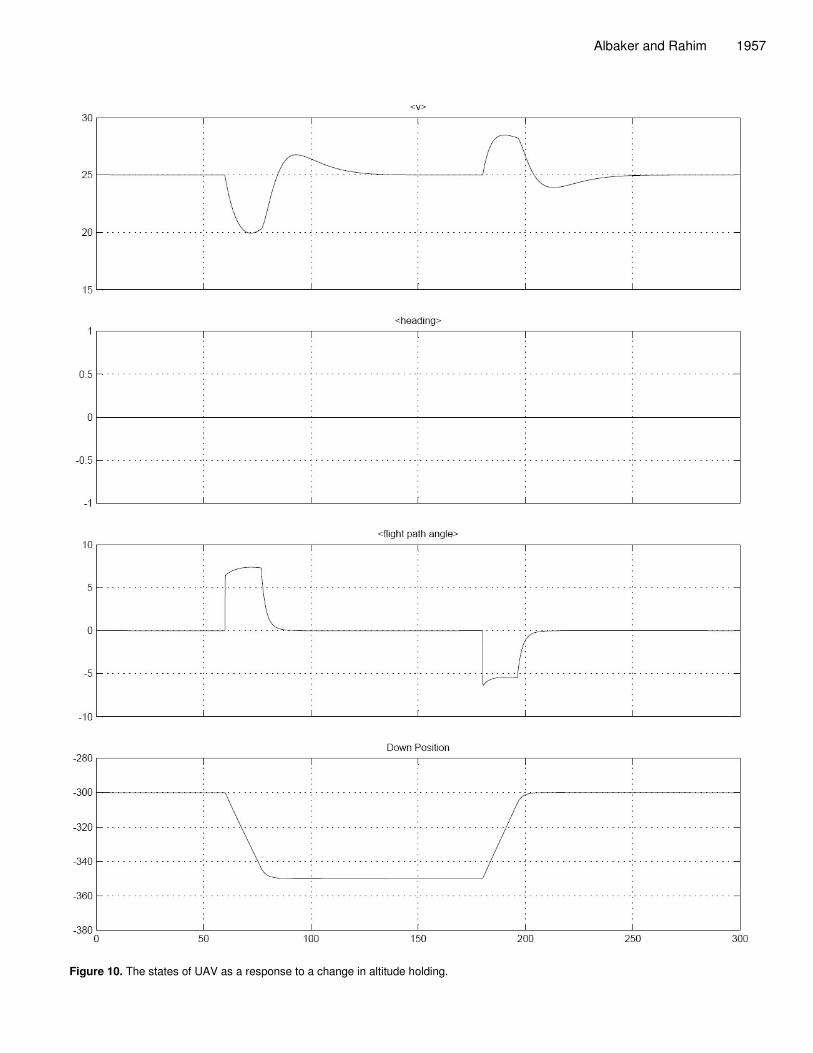
controllers are simulated by changing the desired input states, altitude, heading and velocity commands, in three stages. Each stage was executed for five minutes and includes one desired state change after the first minute of running the simulation program. The simulation is started by executing the simulator with an initial operating condition of 0°C heading, 25 m/s velocity and altitude of 300 m set at its trimmed values with level un-accelerating flight. The altitude command is then issued after the first minute of simulation time to change the state of UAV’s altitude from 300 to 350 m. Another altitude change command is then applied to force a UAV to return back to its earlier altitude level of 300 m. Figure 9 shows the activated control signals from the PID control to UAV for the purpose of following the desired path. Figure 10 illustrates the states of the UAV dynamics as a response to a change in commanded inputs. The heading loop is
simulated by injecting a step input of 82º in the desired heading and keeping other variables without change. A similar procedure is followed to show the effectiveness of the proposed controller. A pulse heading angle command is triggered with value of 82º after the first minute of simulation time with a pulse width of two minutes.
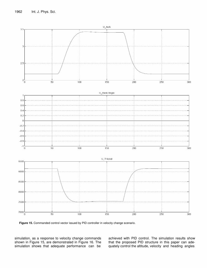
Figures 11 and 12 shows the commanded variables by the controller and the resultant smooth following of the desired turn angle. Next, the turn rate is activated with the heading rate command set at 0.1º/s. Other states are set at their default values. The control vectors together with responses of the UAV dynamics to turn rate change are depicted in Figures 13 and 14. Finally, at the fourth simulation run, the response of the velocity loop is simulated in the same manner by applying a pulse input with a commanded velocity of 20 m/s at the first minute with a pulse width of two minutes. The results of the

1956 Int. J. Phys. Sci.
Figure 9. Commanded control vector issued by PID controller in altitude change scenario.
Albaker and Rahim 1957
Figure 10. The states of UAV as a response to a change in altitude holding.

1958 Int. J. Phys. Sci.
Figure 11. Commanded control vector issued by PID controller in heading change scenario.

Albaker and Rahim 1959
Figure 12. The states of UAV as a response to a change in turn holding.

1960 Int. J. Phys. Sci.
Figure 13. Commanded control vector issued by PID controller in constant heading change scenario.

Albaker and Rahim 1961
Figure 14. The states of UAV as a response to a change in constant turn rate holding.
1962 Int. J. Phys. Sci.
Figure 15. Commanded control vector issued by PID controller in velocity change scenario.
simulation, as a response to velocity change commands shown in Figure 15, are demonstrated in Figure 16. The simulation shows that adequate performance can be
achieved with PID control. The simulation results show that the proposed PID structure in this paper can ade-quately control the altitude, velocity and heading angles

Albaker and Rahim 1963
Figure 16. The states of UAV as a response to a change in airspeed holding.
in response to step inputs. Conclusion
In this paper, a flight path PID controller for a fixed-wing
3DOF UAV is proposed. The proposed control block consists of three PID loops controllers: an airspeed controller, a turn and turn-rate block, and an altitude controller. The system was simulated based on 3DOF fixed-wing equations of motions. This model had lateral

1964 Int. J. Phys. Sci. and longitudinal instabilities that had been corrected with the flight controller using nested PID loops. Simulations were conducted to test the performance of the system. The controller successfully followed the desired path even under small wind disturbance. Although the pro-posed method worked well through various simulations, further improvement will make the system more practical, like it would be a good challenge to introduce adaptive techniques to tune controller parameters in real time. REFERENCES Albaker BM, Rahim NA (2010). Unmanned Aircraft Collision Avoidance
System Using Cooperative Agent-Based Negotiation Approach. Int. J. Simulation, Syst. Sci. Technol., 11(4): 1-8.
Albaker BM, Rahim NA (2011). Autonomous Unmanned Aircraft Collision Avoidance System Based on Geometric Intersection. Int. J. Phys. Sci., 6(3): 391-401.
Andrievsky BR, Fradkov AL (2003). UAV guidance system with combined adaptive autopilot. In the proceedings of the Int. Assoc. Sci. Technol. Dev.. Conf. Intell. Syst. Control, pp. 91–93.
Bekey GA (2005). Autonomous Robots: From Biological Inspiration to Implementation and Control. The MIT Press.
Chao H, Cao Y, Chen Y (2007). Autopilots for small Fixed-Wing Unmanned Air Vehicles: A Survey. In the Proceedings of the IEEE International Conference on Mechatronics and Automation. China, pp 3144-3149.
Christophersen H, Pickell RW, Neidhoefer JC, Koller AA, Kannan SK, Johnson EN (2006). A Compact Guidance, Navigation, and Control System for Unmanned Aerial Vehicles. J. Aerospace Comput. Info. Commun., 3(5): 187-213.
Chu CK, Yu GR, Jonckheere EA (1996). Gain scheduling for flyby-throttle flight control using neural networks. Proc. IEEE Conf. Decis. Control, 2: 1557–1562.
Clancy LJ (1975). Aerodynamics. Pitman Publishing Limited, London. Department of Defense (DoD) (2010). U.S. Army Unmanned Aircraft
Systems Roadmap 2010-2035. Secretary of Defense Office. US Fort Rucker, Alabama.
Fernandez MA, Shram G, Vingerhoeds R, Vebruggen H, Mulder JA (1999). Windshear recovery using fuzzy logic guidance and control. J. Guid. Control Dyn., 22(1): 178–180.
Grasmeyer J, Keennon MT (1998). Development of the black widow micro air vehicle. Proc. IEEE Conf. Decis. Control, pp 3629–3634.
Hess RA (1995). Feedback system design for stable plants with input saturation. J. Guid. Control Dyn., 18(5): 1029–1035.
Johnson EN, Kannan S (2002). Adaptive flight control for an autonomous unmanned helicopter. In AIAA Guidance, Navigation and Control Conference. Monterey, CA, Number AIAA-2002-4439.
Kaminer I, Pascoal AM, Khargonekar PP, Coleman EE (1995). A velocity algorithm for the implementation of gain-scheduled controllers. Automatica, 31(8): 1185–1191.
Kaminer I, Pascoal AM, Hallberg R, Silvestre C (1998). Trajectory tracking for autonomous vehicles:An integrated approach to guidance and control. J. Guid. Control Dyn., 21(1): 29–38.
Khammash M, Zou L (1999). Robust aircraft pitch-axis control
underweight and center of gravity uncertainty. Proc. IEEE Conf. Decis. Control. pp 1970–1975.
Koo TJ, Sastry S (1998). Output tracking control design of a helicopter model based on approximate linearization. Proc. IEEE Conf. Decis. Control, 4: 3635–3640.
Kumon M, Udo Y, Michihira H, Nagata M, Mizumoto I, Iwai Z (2006). Autopilot system for Kiteplane. IEEE/ASME Trans. Mechatronics, 11(5): 615–624.
Long LN, Hanford SD, Janrathitikarn O, Sinsley GL, Miller JA (2007). A Review of Intelligent Systems Software for Autonomous Vehicles. IEEE Symposium on Computational Intelligence for Security and Defense Applications. Hawaii, pp 69 – 76.
Lyshevski SE (2001). Distributed control of MEMS-based smart flight surfaces. Proc. Am. Control Conf., 3: 2351–2356.
Montogomery J, Bekey GA (1998). Learning helicopter control through teaching by showing. Proc. IEEE Conf. Decis. Control. 4: 3647–3652.
Muse J , Tchieu A , Kutay AT, Chandramohan R, Calise AJ, Leonard A (2009). Vortex Model Based Adaptive Flight Control Using Synthetic Jets. AIAA Guidance Navigation and Control Conference. Chicago, Illinois.
Rifai H, Marchand N, Poulin G (2009). Attitude and Position Control of a Flapping Micro Aerial Vehicle. Aerial Vehicles. In-Tech Publication.
Sadraey M, Colgren R (2005). 2 DOF robust nonlinear autopilot design for a small uav using a combination of dynamic inversion and h-infinity loop shaping. In IAA Guidance, Navigation, and Control Conference and Exhibit. San Francisco, California, number AIAA-2005-6402.
Santoso F, Liu M, GK Egan (2007). Linear quadratic optimal control synthesis for a uav. In 12th Australian International Aerospace Congress. AIAC12, Melbourne, Australia, number AIAA- 2002-4439.
Schenato L, Campolo D, Sastry S (2003). Controllability issues in flapping flight for biomimetic micro aerial vehicles(MAVs). In the proceedings of the IEEE Conference Decision Control, 6: 6441–6447.
Shim H, Koo T, Hoffmann F, Sastry S (1998). A comprehensive study of control design for an autonomous helicopter. Proc. IEEE Conf. Decis. Control, 4: 3653–3658.
Shtessel Y, Buffington J, Banda S (1998). Multiple time scale flight control using re-configurable sliding modes. Proc. IEEE Conf. Decis. Control, 4: 4196–4201.
Sugeno M, Hirano I, Nakamura S, Kotsu S (1995). Development of an intelligent unmanned helicopter. Proc. IEEE Int. Fuzzy Syst. Conf., 5: 33–34.
Vascak KHJ, Kovacik P, Sincak P (2001). Performance-based adaptive fuzzy control of aircrafts. Proc. IEEE Int. Fuzzy Syst. Conf., 2: 761–764.
Wu H, Sun D, Zhou Z (2004). Micro air vehicle: Configuration, analysis, fabrication, and test. IEEE/ASME Trans. Mechatronics, 9(1): 108–117.
Zipfel PH (2007). Modeling and Simulation of Aerospace Vehicle Dynamics. 2nd Edition American Institute of Aeronautics and Astronautics, (AIAA).