flight model development of planet-c telecommunication
TRANSCRIPT

Trans. JSASS Aerospace Tech. JapanVol. 8, No. ists27, pp. Tj_17-Tj_22, 2010
Topics
Copyright© 2010 by the Japan Society for Aeronautical and Space Sciences and ISTS. All rights reserved.
Tj_17
Flight Model Development of PLANET-C Telecommunication Subsystem
By Tomoaki TODA, Tomoko HAYASHIYAMA, Yukio KAMATA, Nobuaki ISHII and Masato NAKAMURA
Japan Aerospace Exploration Agency, Institute of Space and Astronautical Science, Sagamihara, Japan
(Received July 3rd, 2009)
PLANET-C (PLC) is the mission of Japan Aerospace Exploration Agency (JAXA) for Venus exploration. It is a successor of HAYABUSA in the history of Japanese deep space missions and is expected to be the first Japanese planetary orbiter. The spacecraft will be launched in the summer of 2010 from Tanegashima Space Center. The mission has demanded new onboard telecommunication instruments. Among them are X-band digital transponder, high gain flat antenna, and low gain wider field of view antenna. Through their developments, new technologies such as deep space regenerative ranging adapted for JAXA ground stations have been successfully incorporated into the PLC system. They are now raedy for their first space-borne demonstration. We will discuss these telecommunication technologies newly introduced for the PLC mission.
Key Words: PLANET-C, Deep Space Telecommunication, Regenerative Ranging, Slot Array Antenna, Lens Antenna
1. Introduction PLANET-C (PLC) is the Venus exploration mission of Japan Aerospace Exploration Agency (JAXA). The spacecraft is sometimes called as Venus Climate Orbiter. Because it aims unveiling climate dynamics hidden in the thick Venusian atmosphere. We are challenged to answer the questions on how today’s Venusian climate is formed. We also expect that discoveries obtained through PLC mission will help us understand more on our planet, Earth1). The spacecraft size is 1.4m (width), 1.45m (depth), and 1.04m (height). It has wings of solar panel of 1.2m2 on the sides (see Fig. 2). The wet mass is 500kg. It will be launched by H-II-A from Tanegashima Space Center in the summer of 2010 and be placed into the orbit directly heading for Venus. After a half a year journey, PLC will be transferred into the Venus orbit. It will stay there at least for 2 years for the continual Venus observations using onboard imagers from infrared to ultra violet. PLC employs newly developed communication instruments for the mission. Among them are X-band digital transponder (X-TRP), high-gain antenna (HGA), low-gain antenna (LGA), traveling wave tube amplifier (TWTA), and so on. They have been developed to support not only PLC, but also JAXA deep space missions in the next decade. Toward the launch of PLC in the next summer, the ground validation of flight models (FMs) of these instruments is being conducted. We will begin our discussion with the design of PLC telecommunication subsystem, and then continues to the development of X-TRP, HGA, and LGA. 2. Telecommunication Subsystem of PLANET-C PLC uses an X-band channel allocated for deep space missions. The channel is a pair of uplink and downlink with their frequency ratio as 749 to 880. 2.0MHz and 3.4MHz bandwidth are given to the uplink and downlink channel respectively. They are for tracking, telemetry and command (TT&C) operations. All the TT&C operations of PLC will be conducted at Usuda Deep Space Center (UDSC) 64m station
with Uchinoura Space Center (USC) 34m station or Deep Space Network as backups. Figure 1 is the PLC onboard telecommunication subsystem. The total mass of the telecommunication subsystem is 25.4kg without taking an ultra stable oscillator (USO) into account. The nominal power consumption is 93.2W when using a TWTA for data transmission. The system is composed of redundant X-TRPs and power amplifiers, a set of antennas including low, medium, and high gain, and a switch matrix connecting them with each other. The LGAs are for the use in the initial checkout phase and a recovery from safe modes. The medium gain antennas (MGAs) are for the telemetry link in safe modes and a backup of HGA operations. The LGA and MGA are used for both uplink and downlink. However, PLC has two HGAs for each uplink and downlink. They are placed on the same aspect of the spacecraft body and function as one. As far as no spacecraft attitude troubles are experienced in the orbit, we use only HGAs for the spacecraft-earth link. PLC has both the TWTA and solid-state power amplifiers (SSPAs). The SSPAs are for the tests on the ground and the link during cruising phase. The TWTA will be activated only after a series of post-launch tests lasting for a month. Once we start using the TWTA, the SSPAs become backups for it. The output power of TWTA is limited by PLC thermal conditions encountered in the Venus orbit. They allow 20W output power for the TWTA, but 10W for the less power-efficient SSPA. Figure 2 is the outside look of PLC together with its schematic antenna coverage. The coordinate of the spacecraft is indicated, too. Note that the spacecraft dimensions in the section 1 are given when we see from the panel toward +Z direction. The HGAs for uplink and downlink are placed on this +Z panel. The larger one is for downlink and the smaller one is for uplink. The MGAs are on the panel of +Y direction with one-axis gimbals beneath it. They cover +Z and –Z direction in the X-Y plane, respectively. The one for +Z direction is more frequently used as a backup for the HGAs. The LGAs are on the +X and –X panel. When each are routed to redundant X-TRPs, they can cover the whole directions while keeping the antenna gain more than -5dBi for reception. PLC transfers to this safe mode configuration in case of a

Trans. JSASS Aerospace Tech. Japan Vol. 8, No. ists27 (2010)
Tj_18
contingency. The link design of PLC to keep 3dB margin is summarized in Fig. 3. The ground station is UDSC. The PLC telecommunication scheme complies with Consultative Committee for Space Data Systems (CCSDS) standards. The CCSDS concatenated coding with interleaving of two is applied to the PLC telemetry link. The highest bit rate of PLC command link and of telemetry link is 1kbps and 32kbps, respectively. In Fig. 3, the results for command link and telemetry link are separately presented just for the convenience of visibility. The discussion of ranging link is taken up in the later section. Figure 3 is the relationship between available bit rate and spacecraft-Earth distance. Based on the worst scenario of PLC, the LGA link in the safe mode and the MGA and HGA link in the nominal mode are presented. Because the spacecraft attitudes in safe modes are different between the cruising phase and the Venus orbiting phase, there are two LGA links in Fig.3. We used arrows in the figure to indicate mission phases. PLC will arrive at Venus when the distance from Earth is around 0.6AU. Thus, the cruising phase is expressed as an arrow from 0AU to 0.6AU in Fig.3. After the arrival at Venus, the spacecraft–Earth distance varies between 0.3AU and 1.7AU during two years observation in the Venus orbit. Hence, the Venus orbiting phase is from 0.3AU to 1.7AU. According to Fig.3, the LGA successfully keeps a command link all the time
of the mission (See CMD LGA Link in Fig.3.). But only the lowest bit rate of 15.625bps is available in most of the Venus orbiting phase. However, we need the MGA to establish an emergency telemetry link (See TLM LGA and MGA Link in Fig.3) during the entire span of the mission. Even then, we must take it into consideration that the available telemetry rate is lowered to 32bps. Anyway, PLC needs both the LGA and MGA to survive the mission. In the nominal case, the HGA helps us to use a higher bit rate link. From Fig.3, we expect the constant 1kbps command link at any time and the telemetry link varying between 4kbps and 32kbps in the Venus orbit (See COM HGA and TLM HGA Link in Fig.3). In this link condition, maximizing the span when the 32kbps telemetry is available is meaningful for the increase of science data acquisition within two years of the mission. This is important when designing the PLC orbit. 3. Newly Developed Telecommunication Instruments for PLANET-C The X-TRP, HGA, and LGA are new. The PLC mission is the first to adopt them as flight components. We anticipated the mass and size reduction, improved power efficiency, and availability of new functions to enlarge link distances through their adoption. We will discuss their benefits in the followings. 3.1. X-Band digital transponder The X-TRP is an in-house product of JAXA. Based on the knowledge accumulated in the past JAXA deep space missions, that is, NOZOMI and HAYABUSA, the compact and versatile digital transponder breadboard model (BBM) was developed2). The effort raising a technology readiness level (TRL) from BBM to FM followed through the PLC mission under supervision of JAXA. Figure 4 is the X-TRP developed for PLC. Among the new properties of the X-TRP are regenerative ranging, an ultra low phase noise performance, and a cost reduction gained from the in-house development. We will take
HGA-R HGA-T LGA-B
MGA-AMGA-B
LGA-A
Fig. 2. PLANET-C and its schematic antenna coverage.
Fig. 1. PLANET-C telecommunication subsystem. Acronyms are as follows. X-TRP: X-band Transponder, USO: Ultra Stable Oscillator, SSPA: Solid State Power Amplifier, LPF: Low Pass Filter, EPC: Electric Power Conditioner, TWTA: Traveling Wave Tube Amplifier, HGA: High Gain
Antenna, MGA: Medium Gain Antenna, and LGA: Low Gain Antenna.

T. TODA et al.: Flight Model Development of PLANET-C Telecommunication Subsystem
Tj_19
up the regenerative ranging in the following. The regenerative ranging was proposed to enhance a ranging link coverage in deep space activities3). We had started our development so soon that our scheme was different from the CCSDS recommendation issued much later4). We thought highly of the compatibility with our existing ranging system when we design our regenerative ranging scheme. This idea successfully suppressed our development and introduction cost for ground stations. Moreover, it is also important to introduce this technology so as to be in time for the PLC mission Thus, it is not always good to stick to standards. Our ranging code is a logical AND product of Pseudo Noise (PN) sequence of 255 and 511. It is never special as a code of PN ranging. Hence, If only ground stations are capable of generating an arbitrary combination of general PN codes for their ranging, our regenerative ranging works in those stations. The onboard regeneration process is our own, too. The solution adopted by oversea agencies is to develop an onboard correlator specific to ranging codes. But a space-borne special device is needed for an onboard rapid correlation process to detect PM code components. The alternative method is a synchronous integration based only on periodicity of ranging codes. This is what we proposed for our regenerative ranging. Periodical components of 255 and 511 of PN codes are embedded in our code. Its signal quality recovery is less efficient than that achieved by the correlation method. But the scheme is so simple that it is easily implemented in a built-in field programmable gate array (FPGA) of the X-TRP. We did not need any more expensive devices to implement our regenerative ranging in our X-TRP. It is also notable that the less efficiency mentioned above is finally recovered at the cost of a longer onboard integration time. Though it causes a longer delay in the turn-around process inside of the X-TRP, it is acceptable in most cases of deep space operations in which a much longer round-trip propagation delay exists. The implementation of our regenerative ranging in our X-TRP BBM is summarized in 2). It is composed of Doppler aiding for ranging codes, synchronous integration, code decision, and code regeneration for retransmission. Comparing with the regeneration process applied to near-earth satellites, the most
distinctive point is Doppler aiding. The long time integration is inevitable for the regeneration of an extraordinary weak ranging signal received by deep space spacecraft. Thus, the X-TRP needs a frequency and phase pinning function over the integration time. This is so called Doppler aiding. Without this function, the signal restoration for regeneration is impossible. For this cancellation, Doppler information extracted from uplink carrier acquisition is utilized based on the fact that the carrier frequency and ranging code chip rate is coherent. The advantage of regenerative ranging was investigated using the X-TRP BBM. Figure 5 is the comparison between our conventional turn-around ranging and regenerative ranging. As far as we know, this is the first experimental result to prove that the deep space regenerative ranging based on the synchronous integration is superior to conventional one. The regenerative ranging works and keeps better accuracy even at much worse signal conditions beyond the conventional limit. The measurement conditions are as indicated in Fig. 5. The integration time was set at 10 seconds. The modulation index was fixed at 1.0 radian for uplink and 0.9 radians for downlink. To simulate realistic onboard turn-around conditions, the uplink and downlink carrier to noise power density ratio (C/No) was selected so that the uplink is always 22dB better
1
1 0
1 0 0
1 0 0 0
1 04
1 05
0 0 .5 1 1 .5 2
TLM LGA Link in Cruising PhaseTLM MGA LinkTLM HGA Link
Ava
ilable
Bit R
ate [
bps]
Spacecraft Distance from Earth [AU]
Cruising Phase Mission Phase in Venus Orbit
Max. TLM bit rate: 32kbps
1
1 0
1 0 0
1 0 0 0
1 04
0 0 .5 1 1 .5 2
CMD LGA Link for Cruising PhaseCMD LGA Link in Venus OrbitCMD MGA LinkCMD HGA Link
Ava
ilable
Bit R
ate [
bps]
Spacecraft Distance from Earth [AU]
Cruising PhaseMission Phase in Venus Orbit
Max. CMD bit rate: 2kbps
Fig. 4. X-band Digital Transponder developed for PLANET-C.
Fig. 3. Link design of the PLANET-C mission. Available bit rates for LGA, MGA, and HGA link with 3dB margin left are indicated as lines when the spacecraft–Earth distance varies from 0AU to 1.7AU. The left one is for command (CMD) link and the right one for telemetry (TLM) link.

Trans. JSASS Aerospace Tech. Japan Vol. 8, No. ists27 (2010)
Tj_20
than the downlink. It corresponds to the condition that we usually experience when we operate our spacecraft at UDSC. The theoretical accuracy of ranging and carrier to noise power density ratio is related with the following formula.
TCLN
r ⋅⋅= 0
4πλσ
,where σr is an accuracy of ranging, λ is a wavelength of ranging subcarrier, C/No is a downlink carrier to noise power density ratio, L comes from a total loss experienced during turn-around process, and T is an integration time. In this expression, the modulation loss is also included in L. The difference between the regenerative ranging and the conventional turn-around ranging is produced from L. Due to an uplink degradation, L for the conventional turn-around ranging is smaller than that for the regenerative ranging. While the uplink degradation is negligible (See the region with C/No more than 40dBHz in Fig.5), the difference of L is negligible. However, the uplink degradation gradually makes difference between them. The L for the regenerative ranging is basically determined only by a downlink modulation loss. Thus, the behavior of the regenerative ranging in Fig.5 is linear when C/No varies. The results of both ranging schemes well fit to the theoretical lines. Both are measured to the limits defined later in this paragraph while decreasing the downlink C/No step by step. In both ranging, the ranging code acquisition starts failing below the limits. The integration time more than 10 seconds is needed for a better performance beyond them. At each measurement point, we carried out 50 times ranging. The number of failure gradually increases when lowering C/No. In this experiment, the limit was defined as C/No where no raging failure was occurred in the 50 times trials. The regenerative ranging was
successfully conducted to the level of 14.5dBHz keeping 10 m accuracy, and the turn-around ranging was to the level of 26.5dBHz keeping the same 10m accuracy. We can say that the 12dB of regenerative gain was obtained at the 10 m accuracy. Here, we defined the regenerative gain as a difference of required downlink C/No at the same accuracy between the turn-around and regenerative ranging, while keeping other conditions such as a modulation index equal. Figure 6 is the integration time T in the formula against downlink C/No required to achieve the corresponding ranging accuracies. The same ranging conditions as Fig. 5 except for the integration time applies to Fig. 6. According to them, the 1m accuracy demands an integration time of around 180 seconds for the regenerative ranging when the received downlink C/No is 20dBHz. However, the turn-around ranging demands 17000 seconds for the same performance. This integration time is no more a realistic value in the spacecraft operation. Figure 6 simply let us know how strongly the regenerative ranging of our X-TRP supports ranging operations of PLC when C/No is degraded.
Fig. 5. The comparison of accuracy between JAXA regenerative ranging and conventional turn-around ranging. The theoretical lines and experimental results using X-TRP BBM show good accordance between them.
Fig. 6. Required integration time against downlink C/No. The result of regenerative ranging (upper) and conventional turn-around ranging (lower) are indicated. The same calculation conditions as Fig. 5 are applied to Fig. 6.
1
10
100
1000
0 10 20 30 40 50 60
σr = 0.1mσr = 0.5mσr = 1mσr = 5mσr = 10mσr = 50mσr = 100m
Inte
grat
ion
Tim
e [s
]
Downlink Carrier to Noise Power Density Ratio [dBHz]
0.01
0.1
1
10
10 20 30 40 50 60
Regenerative RangingTurn-Around RangingTheoretical (Regenerative)Theoretical (Turn-Around)D
evi
atio
n σ
r[m]
Downlink Carrier to Noise Power Density Ratio [dBHz]
Uplink Received C/No - Downlink Received C/No = 22dB.
Uplink Mod. Index = 1.0rad. Downlink Mod. Index = 0.9rad.
Ranging Subcarrier(SC) Frequency = 436.942kHz.
Ranging Signal : PN511∩PN255. 1/4 Rate of SC.
Ranging Integration Time = 10s.
Onboard Turn-Around Filter Bandwidth = 1MHz.
1
10
100
1000
0 10 20 30 40 50 60
σr = 0.1mσr = 0.5mσr = 1mσr = 5mσr = 10mσr = 50mσr = 100m
Inte
grat
ion T
ime [
s]
Downlink Carrier to Noise Power Density Ratio [dBHz]
T. TODA et al.: Flight Model Development of PLANET-C Telecommunication Subsystem
Tj_21
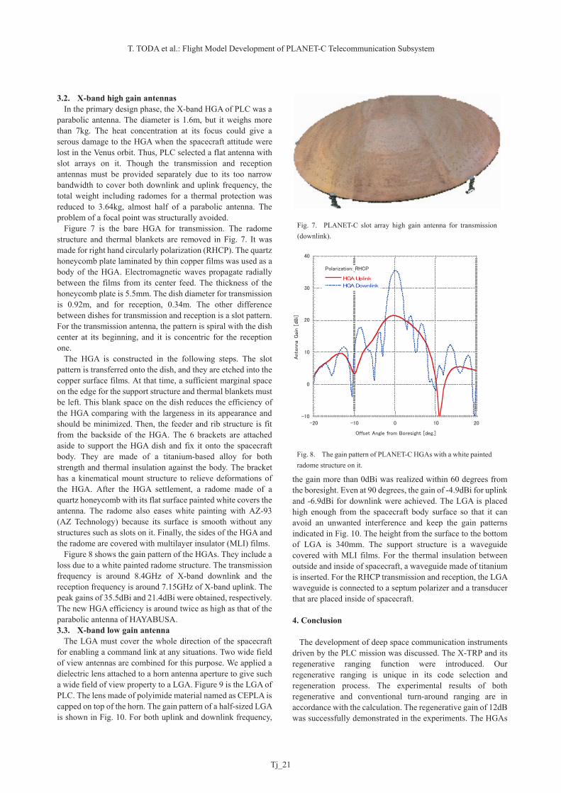
3.2. X-band high gain antennas In the primary design phase, the X-band HGA of PLC was a parabolic antenna. The diameter is 1.6m, but it weighs more than 7kg. The heat concentration at its focus could give a serous damage to the HGA when the spacecraft attitude were lost in the Venus orbit. Thus, PLC selected a flat antenna with slot arrays on it. Though the transmission and reception antennas must be provided separately due to its too narrow bandwidth to cover both downlink and uplink frequency, the total weight including radomes for a thermal protection was reduced to 3.64kg, almost half of a parabolic antenna. The problem of a focal point was structurally avoided. Figure 7 is the bare HGA for transmission. The radome structure and thermal blankets are removed in Fig. 7. It was made for right hand circularly polarization (RHCP). The quartz honeycomb plate laminated by thin copper films was used as a body of the HGA. Electromagnetic waves propagate radially between the films from its center feed. The thickness of the honeycomb plate is 5.5mm. The dish diameter for transmission is 0.92m, and for reception, 0.34m. The other difference between dishes for transmission and reception is a slot pattern. For the transmission antenna, the pattern is spiral with the dish center at its beginning, and it is concentric for the reception one. The HGA is constructed in the following steps. The slot pattern is transferred onto the dish, and they are etched into the copper surface films. At that time, a sufficient marginal space on the edge for the support structure and thermal blankets must be left. This blank space on the dish reduces the efficiency of the HGA comparing with the largeness in its appearance and should be minimized. Then, the feeder and rib structure is fit from the backside of the HGA. The 6 brackets are attached aside to support the HGA dish and fix it onto the spacecraft body. They are made of a titanium-based alloy for both strength and thermal insulation against the body. The bracket has a kinematical mount structure to relieve deformations of the HGA. After the HGA settlement, a radome made of a quartz honeycomb with its flat surface painted white covers the antenna. The radome also eases white painting with AZ-93 (AZ Technology) because its surface is smooth without any structures such as slots on it. Finally, the sides of the HGA and the radome are covered with multilayer insulator (MLI) films. Figure 8 shows the gain pattern of the HGAs. They include a loss due to a white painted radome structure. The transmission frequency is around 8.4GHz of X-band downlink and the reception frequency is around 7.15GHz of X-band uplink. The peak gains of 35.5dBi and 21.4dBi were obtained, respectively. The new HGA efficiency is around twice as high as that of the parabolic antenna of HAYABUSA. 3.3. X-band low gain antenna The LGA must cover the whole direction of the spacecraft for enabling a command link at any situations. Two wide field of view antennas are combined for this purpose. We applied a dielectric lens attached to a horn antenna aperture to give such a wide field of view property to a LGA. Figure 9 is the LGA of PLC. The lens made of polyimide material named as CEPLA is capped on top of the horn. The gain pattern of a half-sized LGA is shown in Fig. 10. For both uplink and downlink frequency,
the gain more than 0dBi was realized within 60 degrees from the boresight. Even at 90 degrees, the gain of -4.9dBi for uplink and -6.9dBi for downlink were achieved. The LGA is placed high enough from the spacecraft body surface so that it can avoid an unwanted interference and keep the gain patterns indicated in Fig. 10. The height from the surface to the bottom of LGA is 340mm. The support structure is a waveguide covered with MLI films. For the thermal insulation between outside and inside of spacecraft, a waveguide made of titanium is inserted. For the RHCP transmission and reception, the LGA waveguide is connected to a septum polarizer and a transducer that are placed inside of spacecraft. 4. Conclusion The development of deep space communication instruments driven by the PLC mission was discussed. The X-TRP and its regenerative ranging function were introduced. Our regenerative ranging is unique in its code selection and regeneration process. The experimental results of both regenerative and conventional turn-around ranging are in accordance with the calculation. The regenerative gain of 12dB was successfully demonstrated in the experiments. The HGAs
Fig. 7. PLANET-C slot array high gain antenna for transmission (downlink).
Fig. 8. The gain pattern of PLANET-C HGAs with a white painted radome structure on it.
-10
0
10
20
30
40
-20 -10 0 10 20
HGA Uplink
HGA Downlink
Ante
nna
Gai
n [
dBi]
Offset Angle from Boresight [deg.]
Polarization: RHCP

Trans. JSASS Aerospace Tech. Japan Vol. 8, No. ists27 (2010)
Tj_22
and LGAs were also developed for the PLC mission. The flat HGA based on the quartz honeycomb material for deep space missions was demonstrated for the first time. The wide field of view lens antenna was introduced as the LGA. The flight model of these components are now settled in the PLC spacecraft and waiting for its launch. It will be their first space-borne demonstration. Acknowledgement Authors would like to appreciate Mr. Osamu Amano and his colleagues for their contribution to the development of HGAs and LGAs. We also would like to express gratitude to Mr. Hideho Tomita and Mr. Hajime Ishimaru for their support to conduct a series of tests on the regenerative and turn-around ranging of X-TRP.
Reference 1) Imamura, T., Nakamura, M., Ueno, M., Iwagami, N., Satoh, T.,
Watanabe, S., Taguchi, M., Takahashi, Y., Suzuki, M., Abe, T., Hashimoto, G.L., Sakanoi, T., Okano, S., Kasaba, Y., Yoshida, J., Yamada, M., Ishii, N., Yamada, T., and Oyama, K.-I.: PLANET-C: Venus Climate Orbiter mission of Japan, Planet. Space Sci., 55 (2007), pp.1831-1842.
2) Toda, T., Saito, H., Yamamoto, Z., Tomita, H., Sagawa, K., Yamada, S., and Sugiyama, K.,: X-Band Deep Space Digital Transponder and Regenerative Ranging, JAXA Research and Development Report, JAXA-RR-04-005E (2004).
3) Berner, J.B., Layland, J.M., Kinman, P.W. and Smith, J.R.,: Regenerative Pseudo-Noise Ranging for Deep Space Applications, JPL TMO Progress Report, 42-137 (1999), pp.1-18.
4) Pseudo-Noise (PN) Ranging Systems, CCSDS 414.1-B-1, Blue Book, Issue 1 (2009).
-80
-60
-40
-20
0
20
015
30
45
60
75
90
105
120
135
150
165180
195
210
225
240
255
270
285
300
315
330
345
Uplink 7.15GHz
Downlink 8.4GHz
Annte
na
Gai
n [
dBi]
Polarization: RHCP
Fig. 10. The gain patterns of half-sized PLANET-C LGA.
Fig. 9. PLANET-C low gain lens antenna on top of the waveguide structure.