flight manual ash 31 mi flight manual - alexander schleicher · flight manual ash 31 mi flight...
TRANSCRIPT

Flight Manual ASH 31 Mi Flight Manual
2.3 Airspeed Indicator Markings Airspeed indicator markings and their colour-code significance are shown below.
Marking IAS value or range Significance
White Arc 90 – 160 km/h 49 – 86 kts 56 – 99 mph
Positive Flap Operating Range
Green Arc 99 – 200 km/h 53 – 108 kts 62 – 124 mph
Normal Operating Range (neutral flap setting)
Yellow Arc 200 – 270 km/h108 – 146 kts 124 – 168 mph
Manoeuvres must be con-ducted with caution and only in smooth air
Red Line 270 km/h 146 kts 168 mph
Maximum speed for all op-erations
Yellow Triangle 105 km/h 57 kts 65 mph
Approach speed at max. weight without water ballast
Blue Line 97 km/h 52 kts 60 mph
Best rate-of-climb speed vy
Issue: 01.10.2011 mh App. Revision:
2.5

Flight Manual ASH 31 Mi Flight Manual
2.4 Power-Plant Engine: IAE50R-AA
Maximum power,
take-off: 37.3 kW (3 minute limit) 7750 rpm
continuous: 35.8 kW 7100 rpm
Maximum take-off revs: 7750 rpm
Maximum continuous revs: 7100 rpm
Maximum overspeed revs: (20 sec.) 8000 rpm Maximum coolant temperature: 100°C 212°F Maximum coolant temperature, take-off: 90°C 194°F
Minimum coolant temperature, take-off: 60°C 140°F
Maximum rotor cooling air temperature: 130°C 266°F NOTE: The above stated take-off performance refers to the
minimum value as given in the engine data sheet. A nominal performance of 41 kW is typical on the other hand.
Lubricant: Total loss oil lubrication at ratio 1:60 approximately Transmission: Toothed belt transmission with 1:2.68 reduction ratio. The following types of propeller are approved: Manufacturer: Alexander Schleicher GmbH Propeller: AS2F1-1/R153-92-N1
App. Issue: 01.10.2011 mh Revision: TN 04 / 05 01.04.2015 mm
2.6

Flight Manual ASH 31 Mi Flight Manual
2.5 Power-Plant Control Unit Markings The following table shows the markings of the digital ILEC Engine Con-trol Unit and explains the meaning of the LED colours in relation to the rpm indication:
1 Green LED
Normal Operating Range
2700 to 7100 rpm
2 Yellow LED
Caution Range, LED blinks after 3 minutes
7100 to 7750 rpm
3 Red LED
Upper limit LC-Display blinks
7750 and higher rpm
Internal Cooling Air Temperature
[°C]
Liquid Coolant Temperature
[°C]
LC-D
ispl
ay
RPM Indication [U/min]
Fuel Quantity [Liter]
1 2 3
For additional display elements see Section 7.9 Power-Plant "Descrip-tion of ILEC Engine Control Unit".
Issue: 01.10.2011 mh App. Revision: TN 04 16.03.2015 mm
2.7

Flight Manual ASH 31 Mi Flight Manual
2.6 Mass (Weight)
Wing span version 18 m 21 m Maximum take-off mass: with water ballast 630 kg 1389 lb 700 kg 1543 lb without water ballast
and with fuel in wing 630 kg 1389 lb 640 kg 1411 lb
Maximum landing mass: 630 kg 1389 lb 700 kg 1543 lbMaximum mass of all non-lifting parts: 365 kg 805 lb 365 kg 805 lb
Maximum mass in baggage compartment: 15 kg 33 lb 15 kg 33 lb
2.7 Centre of Gravity The limits of the C.G. range are as follows:
Wing span version 18 m 21 m forward limit (aft of datum [BP]) 0.29 m 0.95 ft 0.29 m 0.95 ftaft limit (aft of datum [BP]) 0.41 m 1.35 ft 0.38 m 1.25 ft
"BP" (German: Bezugspunkt) stands in this context for "Reference Datum" which is identical with the wing leading edge at the wing root rib. One example of calculating C.G. positions is given in Section 6 of the ASH 31 Mi Maintenance Manual. 2.8 Approved Manoeuvres This powered sailplane is approved for normal sailplane and powered sailplane operation (Airworthiness Category "Utility").
App. Issue: 01.10.2011 mh Revision:
2.8

Flight Manual ASH 31 Mi Flight Manual
the propeller rotates sufficiently for an engine start. Keep in mind to activate the ignition! (5) Insufficient fuel pressure In case the Red LED blinks on the ILEC Engine Control Unit and the display indicates "FUELPRES", first check the position of the fuel cock. Then activate the additional electrical fuel pump. Should the fuel pres-sure still be insufficient, it is permitted to continue powered flight until a safe altitude has been reached and engine temperature limits have not been exceeded. If the internal cooling air temperature remains within the normal range, the engine can be further operated but the fuel sys-tem needs to be checked prior to the next flight. (6) Excessive Engine Temperatures The Red LED blinks on the ILEC Engine Control Unit and the display indicates "AIR 126°" or "H2O 110°". Reduce power settings and check the fuel pressure. Should the tem-perature increase further, stop the engine after having reached a safe altitude and after having carried out an adequate cooling run, retract the engine in accordance with the normal checklist. Continue the flight in the normal gliding configuration. Prior to the next flight the engine has to be checked and maintenance performed if necessary. (7) Cable Fire If possible, stop the power plant and retract it as per check list. On the engine operating console, turn off the main switch and the power plant main switch as well as the avionics main switch in the instrument panel. In case the propeller cannot be retracted, it should be put into a vertical position by means of the propeller stopper. Open the sliding window to allow fresh air into the cockpit.
Issue: 01.10.2011 mh App. Revision: TN 04 16.03.2015 mm
3.11

Flight Manual ASH 31 Mi Flight Manual
(8) Generator warning lamp illuminates If the Red LED "GEN" illuminates on the ILEC Engine Control Unit, the battery voltage has dropped below 12.8 volt. There are three possible reasons:
(1) Too much power consumption is lowering the on-board voltage. Turn off the additional electrical fuel pump after having reached a safe altitude.
(2) The engine battery is in poor condition. (3) The generator has failed.
In case (2): Continue the flight in the normal gliding configuration, but keep in mind that a later engine restart might no longer be possible. In case (3): Climb until a safe altitude has been reached or try to main-tain it. Keep in mind that both fuel pumps and the ignition are now pow-ered by the engine battery. Depending on the charging status and the general condition of the battery, the engine might only remain opera-tional for a short period of time. 3.10 Other Emergencies (1) Jammed Elevator Control System If the flap control is jammed, the ASH 31 Mi is converted into an aircraft with fixed wing profile. However, in case of an emergency with the ele-vator control jammed, the pilot will not always think of the fact that the flaps at least will allow him some degree of pitch control in order to improve his position for bailing out or to avoid it at all. When selecting a more negative flap setting, the pitch angle and the airspeed increase. When selecting a positive flap setting, the pitch angle reduces and the airspeed decreases. It is recommended occasionally to practice this working principle of the flap system while keeping the elevator control fixed.
App. Issue: 01.10.2011 mh Revision: TN 04 / 05 01.04.2015 mm
3.12

Flight Manual ASH 31 Mi Flight Manual
4.4 Pre-Flight Checks The following Check List containing the most important points is affixed within easy view of the pilot.
Issue: 01.10.2011 mh App. Revision:
4.11

Flight Manual ASH 31 Mi Flight Manual
4.5 Normal Operation and Recommended Speeds 4.5.1 Power-Plant Control and Self-Launch Checklist, extending propeller and starting engine - Fuel valve: OPEN - Power-plant main switch: ON (ILEC in operation) - Switch "Extend Propeller" engaged upwards - Green LED "Propeller extended" on ? - Propeller stop disengaged ? - Ignition: ON - Fuel pump 2 OFF - Check fuel pump 1 (must be heard)! - Fuel pressure okay ? No warning message on the ILEC? - ECU ready? (ECU-LED steady RED)? Cold and warm start on the ground (not too cold) - Propeller CLEAR ? - Set THROTTLE to "IDLE" (at lowest position). - Push STARTER button max. 5 seconds - If the engine fails to start, push STARTER button again, after a short
recovery for starter battery. - choose a throttle position at which the engine runs smoothly - Is the red ECU-LED off or constantly on? - Allow the engine to warm up at 4000 rpm for 2 minutes (or up to a
coolant-temperature of 40 °C (104°F)). - Check ignition circuits at 6200 rpm. Maximum drop 300 rpm.
App. Issue: 01.10.2011 mh Revision: TN 04 16.03.2015 mm
4.12

Flight Manual ASH 31 Mi Flight Manual
Cold start (very cold, strongly cooled engine) - Propeller CLEAR ? - Set THROTTLE to "IDLE" (at lowest position). - Push STARTER button max. 5 seconds - If the engine fails to start, push STARTER button again, after a short
recovery for starter battery. - choose a throttle position at which the engine is running smoothly. - Is the red ECU-LED extinct or constantly on? - Allow the engine to warm up at 4000 rpm for 2 to 3 minutes (or up
to a coolant-temperature of 40 °C (104°F)). - Check ignition circuits at 6200 rpm. Maximum drop 300 rpm. Cold and warm start in flight - Air speed 100 to 110 km/h (54 to 59 kts, 62 to 68 mph) - Set THROTTLE to "IDLE" (at lowest position). - Push STARTER button. - Is the red ECU-LED extinct or permanent on ? - If possible, allow engine to warm through. - Reduce airspeed and move throttle to Wide Open Throttle (WOT).
(Watch rate of revolutions!)
Issue: 01.10.2011 mh App. Revision:
4.13

Flight Manual ASH 31 Mi Flight Manual
Checklist stopping engine and retracting propeller - Air speed: 100 - 110 km/h (54 - 59 kts, 62 - 68 mph) - Throttle: IDLE (bottom position). Wait until low rpm have stabilized. - Ignition: OFF - Let engine revs. die down - Engage propeller stop lever (bottom position). When engaging the
stop the propeller must not stand directly above the stop block. - Wait until propeller moves against the propeller stop block - Check vertical position of the propeller by means of the mirror - Press "RETRACT" switch down and hold. Propeller travels into cool-
ing position (beep). After the engine is sufficiently cooled, the LC-display indicates "RETRACT" (pulsating beep). Press the "RE-TRACT" switch again until the ILEC LED "Propeller retracted" lights
- Fuel valve: SHUT - Switch off Power-Plant Main Switch by pushing the red key next to
it. Revolution Rates (rpm) and Speeds Best climb: at vy = 97 km/h = 52 kts = 60 mph (blue line) Cruising speed: 130 to 140 km/h (70 to 76 kts, 81 to 87 mph)
at 7100 rpm Maximum -take-off revs: at 7750 rpm for maximum 3 minutes Maximum -take-off revs: at 7100 rpm The power plant of the ASH 31 Mi gives the possibility to self-launch with good climbing performance, extending the operational range of a pure sailplane. It is advisable to familiarize oneself with the extending and starting procedures initially within safe reach of an airfield, before attempting a cross-country flight. The power plant of a powered sail-plane must not be regarded as a life insurance, for instance when crossing unlandable areas. One should always be prepared for the possibility that the power plant will fail to deliver the hoped-for propul-sion. This may not necessarily be due to a technical shortcoming, but might be caused by nervous tension of the pilot (mistakes in carrying out starting procedure). The engine and its reliability should be re-garded in the same light as that of a sailplane pilot not always finding a thermal when it is most urgently needed. The engines of powered sail-planes are not subject to quite such stringent production and test regu-
App. Issue: 01.10.2011 mh Revision: TN 04 16.03.2015 mm
4.14

Flight Manual ASH 31 Mi Flight Manual
lations as normal aviation engines, and therefore cannot be expected to be quite as reliable. A minimum safe height for extending the propeller and starting the en-gine must be met. The criterion is that it must be possible to retract the propeller again and carry out a normal sailplane out landing if the en-gine cannot be started. A general valid value for this minimum safe height is about 300 meters (980 feet); however, this also depends strongly on pilot ability and geographic factors. The powerplant can be extended and operated at an altitude of 5000 Meter (16,000 ft). Special starting procedures are not required. Even in unfavourable conditions - such as an inexperienced pilot - the loss of altitude is in the order of 50 Meter (150 feet). Idling the engine at 4100 rpm and flying at vY = 97 km/h (52 kts, 60 mph) with a maximum wing loading the rate of sink is approximately 1m/s (2 kts). If it becomes necessary to warm the engine up, a further loss of height of 150 to 200 Meter (500 to 650 feet) should be allowed for. In exceptional cases a cold engine can be operated between 5500 and 6500 rpm which already allows climbing. (1) Extending the propeller Proceed as per checklist.
If the red ECU LED remains off after the ignition is switched on and is followed by a flash code after 10 seconds, then an error has occurred in part of the engine control unit. This has to be repaired prior to the next take-off. In addition, the LC-Display will show an error description in plain text. Further information concerning these error messages is given in section 7.9 of this Flight Manual or in the Engine Manual. If, after turning on the ignition, the Red LED on the ILEC Engine Control Unit blinks and the LC-Display indicates "FUELPRES", there is insufficient fuel pressure for the fuel injection system
Issue: 01.10.2011 mh App. Revision: TN 04 16.03.2015 mm
4.15

Flight Manual ASH 31 Mi Flight Manual
to work properly, causing the engine to develop less than full power. The reason can be a faulty fuel pump or pressure regulator or even a leaking fuel line.
WARNING: In this case the engine must be stopped at once and no self-launching must be attempted.
If the problem occurs during take off at a self-launch it might be possible to restore normal fuel pressure by acti-vating fuel pump number 2. After reaching a safe height the engine has to be shut down and a landing is to be ini-tiated. Prior to the next launch the problem must be fixed.
Do not extend the propeller under higher g-loads. G-forces can in-crease, for instance while circling. In such a case the G-forces can be so high that the electrical jack can extend the propeller only very slowly or fails to do so fully. Speed ranges for extending and retracting the propeller are given in Section 2. (2) Starting the Engine WARNING: A test run of the power plant must under no circum-
stances be performed without the aircraft being com-pletely rigged and safely chocked! In addition, a competent person must be seated in the cockpit.
CAUTION: The local conditions for a safe take-off should be
checked prior to take-off in accordance with the data given in Section 5 of this manual.
Proceed in accordance with checklist. If the engine fails to start, check it over as recommended in the Engine Manual. It makes no sense to press the starter button for more then 5 seconds, as thereby the starter battery is unnecessarily stressed. The mixture generation through an injection system normally permits
App. Issue: 01.10.2011 mh Revision: TN 04 16.03.2015 mm
4.16

Flight Manual ASH 31 Mi Flight Manual
an un-problematic start of the engine. In case of problems, last but not least, an operating error may be assumed. A closed fuel cock is most often the cause of the engine not starting. The red ECU-LED normally remains off when the engine is running. If it is permanently on as long as the engine is running and the LC-Display indicates an error message in plain text, an error has occurred in part of the engine control unit, which has to be repaired prior to the next take-off. If the error message appears during flight and the engine per-forms normally, the flight can be continued. As some sensors do have a backup, an error message does not necessarily immediately affect the power output of the engine. However, as long as an error message is shown, all available values on display should be continually monitored to make sure they are within operating limiting. NOTE: Correction of the indicated error is necessary prior to
the next take-off. At ambient temperatures on the ground, the power plant should warm up for 2 to 4 minutes at 4000 rpm, until the indicator of the coolant tem-perature reacts and indicates about 40°C (104)°F. This will ensure that the engine accelerates smoothly to maximum rpm. If the operating temperature (internal cooling air) is too low, the electronic injection sys-tem automatically reduces the rpm. A safe self launch cannot be made until a static speed of at least 7000 rpm is achieved and the engine is running smoothly. NOTE: In the case of tailwind a lower static rpm will be ob-
served. A headwind will increase the rpm and tailwind will reduce them.
The engine should not be started in temperatures below -10 C (14°F) because there is the danger with a very cold engine that the lubricant oil is too thick and thus the oil feed into the engine could be interrupted.
Issue: 01.10.2011 mh App. Revision: TN 04 16.03.2015 mm
4.17

Flight Manual ASH 31 Mi Flight Manual
(3) Self-Launch - ECU LED OFF ? - Fuel pump 2 as a precaution ON - After approaching a safe altitude: fuel pump 2 OFF - Reduce, after 3 minutes, the maximum take off power to 7100 rpm For a safe self-launch maximum engine, revolutions should come up to 7000 rpm on the ground. With lower revolutions, the pilot must face longer take-off distances than indicated in Section 5.2.3. WARNING: If maximum revolutions on ground are below 7000 rpm,
the aircraft must not take off. First a system check to-gether with a ground run has to be accomplished. In case of doubt, contact the manufacturer.
Experienced pilots should start their take-off run at the most negative Flap setting 1. This Flap setting affords excellent lateral control. At an indicated air speed of about 50 km/h (27 kts, 31 mph) the Flap should be increased to Flap 5 (+10 °). For the following climb Flap 5 should be maintained. For pilots without experience on Flapped aircraft, we recommend Flap setting 5 both during take-off and throughout the climb. For the acceleration run and actual lift-off, the following practices apply for different runway characteristics: Concrete runways: Accelerate with "Wide Open" throttle in Flap setting 1 and slightly push the stick until the tail wheel is unloaded. Up to a speed of about 65 km/h (35 kts, 40 mph) acceleration continues on the main wheel, then set Flap 6 and at the same time gently pull the stick until the aircraft lifts off. After lift-off, climb to between 1 m and 2 m (3 and 6 ft) and acceler-ate slowly to vy = 97 km/h = 52 kts = 60 mph (blue line on ASI scale). Above a minimum safe height of 150 m (500 ft) change to Flap set-ting 5.
App. Issue: 01.10.2011 mh Revision:
4.18
Flight Manual ASH 31 Mi Flight Manual
Nevertheless, in case of cross wind the procedure differs and the tail wheel is loaded by slightly pulling the stick in order to increase direc-tional stability during the ground run. Soft surface runways: Accelerate with wide open throttle at Flap setting 1 and after having gained aileron control, change the flap setting to position 6. Pull the stick back to keep the tail wheel in contact with the ground in order to increase directional stability. Try to lift-off as soon as possible by gently pulling the stick back. Climb afterwards to 1 to 2 m (3 to 6 ft) altitude and accelerate then slowly up to vy. When a safe altitude of 150 m (~500 ft) is reached, switch Flaps to position 5. Maximum acceptable crosswind components are stated in Section 5.3.1. (4) Climbing Flight During climbing flight, the engine should be run at maximum 7750 rpm and at vy. Remember that this take-off power is only allowed for a max-imum of 3 minutes. (5) Cruising Flight This can be carried out in a saw-tooth pattern (climb followed by straight glide with propeller retracted), or in horizontal flight at about 7100 rpm and an air speed of 130 to 140 km/h (70 to 76 kts, 81 to 87 mph ). Monitor fuel reserves and open wing tank valve when neces-sary CAUTION: The wing tank(s) valve will switch off automatically only
if the tank selector switch is set to the "Autom." posi-tion. With manual position "ON" selected, the valve will not close when the fuselage tank is full and fuel will be lost via the overflow vent! Therefore, the fuel level indi-cator must be monitored and the wing tank(s) valve closed in good time.
Issue: 01.10.2011 mh App. Revision: TN 04 16.03.2015 mm
4.19

Flight Manual ASH 31 Mi Flight Manual
CAUTION: If wing fuel tank(s) is(are) fitted, check that the oil sup-ply is sufficient for the completely intended fuel con-tents. Monitor oil warning light!
A detailed description of the ILEC engine control unit is given under Section 7.9. (6) Stopping the Power-Plant CAUTION: To prevent damage to the propeller, the procedures de-
scribed hereafter must be met! With normal outside air and engine temperatures, the flight-testing has shown that there is no need for a longer cooling run. Only with very high engine and outside air temperatures, it is actually necessary to do a longer cooling run – about 1 to 2 minutes- which must then be done in fast level flight. The engine revs must be adjusted between 6400 and 6600 rpm at a speed of about 130 km/h (70 kts, 81 mph). Contrary to a cooling run with the engine idling, the cooling water pump and cooling air fan still operate efficiently at this rpm. A longer cooling flight at lower flight speeds and with the engine idling must not be done, because then the exhaust heats up strongly (the Venturi at the exhaust pipe does no longer supply sufficient cooling air through the outer shroud of the exhaust). The higher temperature of the exhaust silencer does not mean a prob-lem per se for the structure of the fuselage, but if after this cooling run the propeller is at once completely retracted without further waiting time, the hot air from the exhaust silencer may damage the propeller and reduce its service life.
App. Issue: 01.10.2011 mh Revision:
4.20

Flight Manual ASH 31 Mi Flight Manual
(7) Retracting the Propeller The propeller stop block must be swivelled into the arc of the propeller only after the engine rpm have almost completely died down and the propeller is only windmilling. Max. speed is 120 km/h (65 kts, 75 mph). The step by step retraction of the propeller is indispensable to protect the propeller. This procedure serves to cool down the power plant and the exhaust silencer more quickly. Particularly with high outside air temperatures, the pilot must not do without this.
NOTE: While the RETRACT switch is pressed down, the re-traction of the propeller is automatically interrupted af-ter 2/3 of the travel (cooling position). A short signal is audible when this position is reached. The pilot must press the RETRACT switch again in order to retract the propeller entirely.
In practice, the following procedure has been proven effective: After engine shut-off, the liquid coolant temperature first increases a little, because the coolant is no longer being circulated and because the temperature sensor is fitted directly on the engine housing where it immediately indicates its temperature. This temperature must be moni-tored closely and only when the maximum value has dropped by about 2 °C (4 °F) may the propeller be completely retracted without any prob-lems. With the ignition switched off, the internal cooling air temperature value is no longer available, as the engine control unit (ECU), which provides this value to the ILEC Engine Control Unit is no longer active. NOTE: After the engine is sufficiently cooled In the propeller
cooling position the LC-Display indicates "RETRACT" and an additional acoustic signal (pulsating beep) is heard as a reminder that the retraction process has not yet been finished.
Issue: 01.10.2011 mh App. Revision: TN 04 16.03.2015 mm
4.21

Flight Manual ASH 31 Mi Flight Manual
4.5.2 Winch Launch The C.G. tow release at the landing gear must be used for winch launching and Flap setting 4 (+10°) is recommended. For powerful winches capable of providing a high initial acceleration Flap setting 3 should be used. Experienced pilots may change to Flap setting 4 after lift off. CAUTION: Because of its high positive deflection the Flap setting 5
and 6 must not be used. WARNING: The winch driver must be informed to apply a gentle
acceleration. This is especially important with winches featuring a torque converter. Plastic ropes can further enhance acceleration. Use at least Flap setting 3 at the beginning of the launch.
Trim should be set neutral to nose-heavy at any C.G. position. At this trim setting the ASH 31 Mi will assume a gentle climb attitude. With high-powered winches which tend to jerky accelerations, the trim should always be set nose-heavy. Above a minimum safe height the climb should be steepened by applying back pressure on the stick. A weak link of 850 daN ± 10% (Tost No. 2 brown) must be incorpo-rated in the launch cable. Maximum acceptable crosswind component is 20 km/h (10.8 kts, 12.4 mph). NOTE: The wheel CANNOT be retracted during the launch. CAUTION: Winch launching with water ballast is not recommended
at less than 20 km/h (10.8 kts, 12.4 mph) headwind component. The winch driver must be informed of the total Take-Off Mass.
App. Issue: 01.10.2011 mh Revision:
4.22

Flight Manual ASH 31 Mi Flight Manual
7.9 Power Plant The propeller of the power plant unit - when retracted - is accommo-dated in the engine bay in the fuselage behind the wing. It is extended and retracted by means of an electric jack. The following controls are provided for the power plant: - the Control Console (below the instrument panel), - the ILEC Control Unit (fitted in the instrument panel), - the Power Plant Main Switch (fitted in the instrument panel), - the Fuel Valve (left of the seat pan), - the switch for fuel pump 2 (on the instrument panel), - the Rear View Mirror for Propeller Positioning (on the front instru-
ment panel cover or on the instrument panel), - and the Fire Warning Light (red blinking light diode in the instru-
ment panel). - Tank selector switch (next to the ILEC Engine Control Unit)
Issue: 01.10.2011 mh. Revision: TN 04 16.03.2015 mm
7.13
Flight Manual ASH 31 Mi Flight Manual
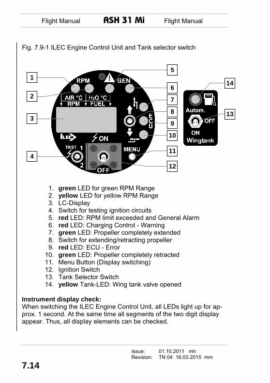
Fig. 7.9-1 ILEC Engine Control Unit and Tank selector switch
12
11
10
9
8
7
6
5
4
3
2
1 14
13
1. green LED for green RPM Range 2. yellow LED for yellow RPM Range 3. LC-Display 4. Switch for testing ignition circuits 5. red LED: RPM limit exceeded and General Alarm 6. red LED: Charging Control - Warning 7. green LED: Propeller completely extended 8. Switch for extending/retracting propeller 9. red LED: ECU - Error 10. green LED: Propeller completely retracted 11. Menu Button (Display switching) 12. Ignition Switch 13. Tank Selector Switch 14. yellow Tank-LED: Wing tank valve opened
Instrument display check: When switching the ILEC Engine Control Unit, all LEDs light up for ap-prox. 1 second. At the same time all segments of the two digit display appear. Thus, all display elements can be checked.
Issue: 01.10.2011 mh Revision: TN 04 16.03.2015 mm
7.14

Flight Manual ASH 31 Mi Flight Manual
Description of ILEC Engine Control Unit
The figures given in the square brackets refer to the numbering in the preceding ILEC Overall View Fig. 7.9-1 Switch for extending and retracting the propeller [8]: The propeller is actuated by the extending/retracting switch, located on the right side of the unit. The switch remains in its “Propeller Extended” position, that is to say the propeller extends fully, when the pilot has given the command. The switch does not have a detent-setting in direc-tion “Propeller Retracted”. This means that the electric jack stops im-mediately (the propeller stops retracting) when the pilot stops pushing the switch. NOTE: While the "Retract" switch is pressed the retraction
process is automatically interrupted after 2/3 of the travel (cooling position). The pilot must press the switch again, if he wants the entire retraction to occur at this point.
When the engine is in the "cooling position", the ILEC constantly moni-tors the Liquid Coolant Temperature. If this temperature drops 2°C from its maximum value or after 6 minutes after ignition is switched off, the exhaust has cooled down enough and the propeller can be retracted completely. The LC-Display message "RETRACT" and a pulsating tone provide a reminder for that. Limit switches fixed at the engine communicate to the micro controller once the end position “retracted” or “extended” is reached. The micro controller then switches off the electric jack. The micro controller prohibits the retraction of the propeller unit as long as the ignition is on in order to prevent dangerous situations. But the propeller can be extended when the ignition is on, the starter however remains deactivated until the propeller is fully extended. To indicate the actual position of the propeller unit to the pilot, two green LED’s [7 and 11] have been positioned above and below the switch respectively. If the propeller is fully retracted, the lower LED [10] is permanently on whereas the upper LED [7] is permanently on once the propeller is fully extended.
Issue: 01.10.2011 mh. Revision: TN 04 16.03.2015 mm
7.15

Flight Manual ASH 31 Mi Flight Manual
At positions between fully extended and fully retracted neither of the LEDs is illuminated since the limit switch signals are missing. NOTE: With ignition ON [12], the propeller can be extended,
but not retracted. Ignition: The ignition is switched on or off by the ignition switch [12]. The ignition switch is protected against unintended activation by means of a safety bracket. The engine can only be retracted when ignition is switched off. With the ignition circuit test switch [4] to the left of the ignition switch, the functioning of the ignition circuits 1 and 2 can be tested separately. For that the ignition circuit 2 is interrupted in switch position 1. Con-versely, the ignition circuit 1 is interrupted in position 2. Fuel pumps: The fuel pump 1 is switched on at the same time as the ignition. In addition, the second fuel pump can be switched on by means of a switch on the instrument panel. However, it is only supplied with current when the ignition is switched on. RPM Measuring: At about 400 RPM the RPM is displayed in four digits at the lower left of the LC-Display [3]. The RPM display has a resolution of 10 RPM. At 7750 RPM the RPM reading starts flashing. To signal that the RPM are approaching the maximum permissible RPM limit, a green [1] and a yellow [2] LED are installed above the RPM display. Each respective LED is on while the RPM are in the cor-responding range. Reaching the yellow range, the green LED extin-guishes and the yellow LED [2] illuminates. Reaching the red range, the yellow LED extinguishes and the Red LED [5] on its right blinks. The latter occurs parallel to the blinking of the RPM-reading. If the speed of 7100 RPM is exceeded for more than 3 minutes, the yellow LED [2] starts to blink and a continuous audible signal will be gener-ated. The RPM ranges are: Green 2700 to 7100 RPM Yellow over 7100 to 7750 RPM Rot over 7750 RPM
Issue: 01.10.2011 mh Revision: TN 04 16.03.2015 mm
7.16

Flight Manual ASH 31 Mi Flight Manual
Fuselage Tank Fuel gauge: The amount of fuel is displayed three digits in litres at lower right (FUEL) on the LC-Display [3]. If the motorglider is equipped with fuel tanks in the wing, the magnetic valve is opened if the fuel level falls below 6 litres. The fuselage tank is now filled up automatically out of the wing tanks. For that to happen, the tank selector switch [13] has to be in the “Automatic” position. If the fuel level in the fuselage tank ap-proaches 12 litres, the valve is closed automatically. The automatic control of the magnetic valve can be switched off (OFF) by the tank selector switch [13] or switched to manual mode (ON). As soon as the magnetic valve opens, the yellow Tank-LED [14] blinks. If the fuel level in the fuselage tank falls below 4 litres, an alarm signal is heard and the LC-display indicates the fuel reserve (FUEL 3L, blink-ing). The alarm signal can be switched off by pressing the menu button [11], but after 4 minutes it will come on again automatically. Calibration of the fuel gauge: With the ignition off, propeller retracted and topped up fuselage tank, the LCD-display can be put into "Calibr.?"(calibration) mode by press-ing the menu button [11] 8 times. Then press the same button [11] for 5 seconds. If the LC-display indicates a calibration value (for example [100]), the calibration procedure is completed. Now the fuselage tank sensor is calibrated to the type of fuel in the reservoir. This calibration value is electronically stored. The calibration has to be repeated when-ever a change of the type of fuel (e.g. from Mogas to Avgas) is under-taken. Recalibrating fuel gauge to include the wing tanks: Turn off ignition, retract engine and top off the fuselage tank. With the menu button [11] the mode "FUEL" is chosen (press 6 times). Then press the same button [11] for 5 seconds. The indication "FUEL" in the LC-display starts blinking. As well, if the menu button is not pushed for 5 seconds, it is now possible to log the total amount of fuel (fuselage and wing tanks) in the aircraft. If during flight the total amount of fuel in the fuselage tank sinks below 4 litres, the number of litres in the wing tank will be reset to zero.
Issue: 01.10.2011 mh. Revision: TN 04 16.03.2015 mm
7.17

Flight Manual ASH 31 Mi Flight Manual
Moving through the pages of the LC-display [3]: LC-display:
Internal Cooling Air Temperature
[°C]
Liquid Coolant Temperature
[°C]
Mai
n pa
ge
RPM Indication [U/min]
Fuel Quantity [Liter]
(comes up automatically after 5 seconds)
Display after pressing the menu button [11]:
Liquid Coolant Temperature [°C]
pres
s 1
time
Range of indication 40°C to 120°C with a resolution of 1°C.
Internal Cooling Air Temperature [°C]
pres
s 2
times
Range of indication 40°C to 128°C with a resolution of 1°C.
Current Fuel Consumption [L/h]
pres
s 3
times
The measured data, provided by the ECU, are indicated as current fuel consumption per hour
Engine Battery Voltage [Volt]
pres
s 4
times
Issue: 01.10.2011 mh Revision: TN 04 16.03.2015 mm
7.18
Flight Manual ASH 31 Mi Flight Manual
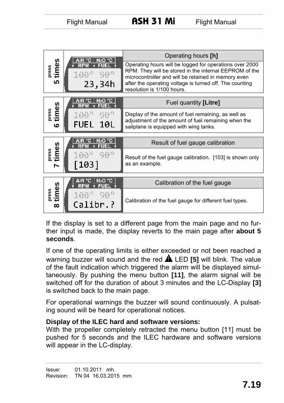
Operating hours [h] pr
ess
5 tim
es
Operating hours will be logged for operations over 2000 RPM. They will be stored in the internal EEPROM of the microcontroller and will be retained in memory even after the operating voltage is turned off. The counting resolution is 1/100 hours.
Fuel quantity [Litre]
pres
s 6
times
Display of the amount of fuel remaining, as well as adjustment of the amount of fuel remaining when the sailplane is equipped with wing tanks.
Result of fuel gauge calibration
pres
s 7
times
Result of the fuel gauge calibration. [103] is shown only as an example.
Calibration of the fuel gauge
pres
s 8
times
Calibration of the fuel gauge for different fuel types.
If the display is set to a different page from the main page and no fur-ther input is made, the display reverts to the main page after about 5 seconds.
If one of the operating limits is either exceeded or not been reached a warning buzzer will sound and the red LED [5] will blink. The value of the fault indication which triggered the alarm will be displayed simul-taneously. By pushing the menu button [11], the alarm signal will be switched off for the duration of about 3 minutes and the LC-Display [3] is switched back to the main page.
For operational warnings the buzzer will sound continuously. A pulsat-ing sound will be heard for operational notices.
Display of the ILEC hard and software versions: With the propeller completely retracted the menu button [11] must be pushed for 5 seconds and the ILEC hardware and software versions will appear in the LC-display.
Issue: 01.10.2011 mh. Revision: TN 04 16.03.2015 mm
7.19

Flight Manual ASH 31 Mi Flight Manual
Notices and warning displays in connection with the red blinking LED [5] and the buzzer:
Display flashes, Buzzer: pulsating tone The engine is in cooling mode and it has cooled suffi-ciently that the propeller can be completely retracted by pushing the retraction switch [8].
Display flashes, Buzzer: pulsating tone
The retraction switch [8] was pushed while the ignition [12] was on.
Display flashes, Buzzer: pulsating tone The starter button was pushed while the propeller was fully extended and the ignition [12] was off.
Display flashes, Buzzer: pulsating tone The starter button was pushed while the ignition [12] was on but the propeller was not fully extended. The starter is disabled until the propeller is fully extended.
Display flashes, Buzzer.: continuous. tone, LED "GEN": flashes red
The on-board voltage has declined to under 11.5 V (at any level of RPM). This is an indication of generator failure. Required power can possibly be supplied by the on-board batteries.
WARNING: The engine may stop at any time.
LED "GEN": lights up red
The LED “GEN” [6] will light as a charging warning as soon as either the RPM drop below 2000 or the battery voltage drops below 12.8 V.
WARNING: Depending on the battery voltage, the pilot has to assume the risk that the igni-tion and the injection unit will fail and the engine stops running.
Display flashes, Buzzer: continuous tone The air cooling temperature has reached 126 °C, which is 4 °C under the maximum permissible temperature. This can be confirmed by pushing menu button [11].
Issue: 01.10.2011 mh Revision: TN 04 16.03.2015 mm
7.20
Flight Manual ASH 31 Mi Flight Manual
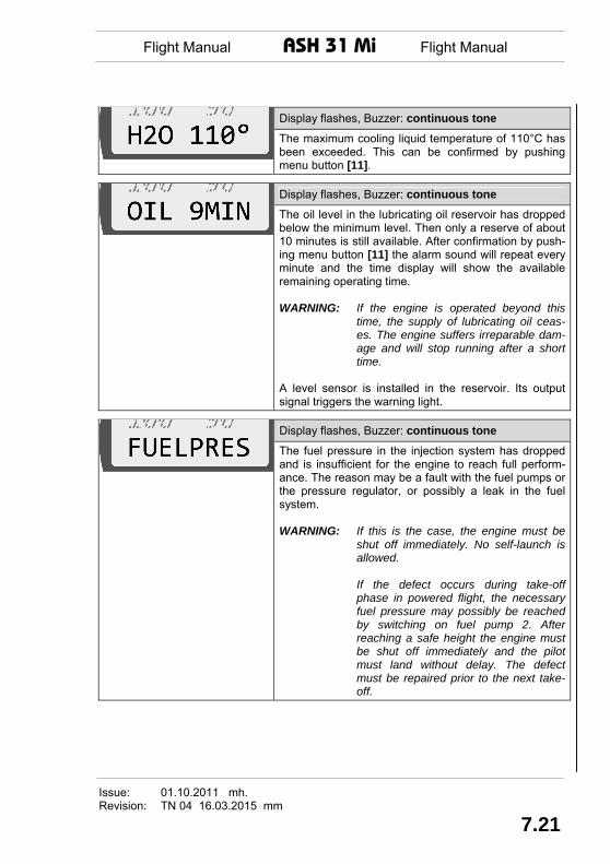
Display flashes, Buzzer: continuous tone The maximum cooling liquid temperature of 110°C has been exceeded. This can be confirmed by pushing menu button [11].
Display flashes, Buzzer: continuous tone The oil level in the lubricating oil reservoir has dropped below the minimum level. Then only a reserve of about 10 minutes is still available. After confirmation by push-ing menu button [11] the alarm sound will repeat every minute and the time display will show the available remaining operating time. WARNING: If the engine is operated beyond this
time, the supply of lubricating oil ceas-es. The engine suffers irreparable dam-age and will stop running after a short time.
A level sensor is installed in the reservoir. Its output signal triggers the warning light.
Display flashes, Buzzer: continuous tone The fuel pressure in the injection system has dropped and is insufficient for the engine to reach full perform-ance. The reason may be a fault with the fuel pumps or the pressure regulator, or possibly a leak in the fuel system. WARNING: If this is the case, the engine must be
shut off immediately. No self-launch is allowed.
If the defect occurs during take-off
phase in powered flight, the necessary fuel pressure may possibly be reached by switching on fuel pump 2. After reaching a safe height the engine must be shut off immediately and the pilot must land without delay. The defect must be repaired prior to the next take-off.
Issue: 01.10.2011 mh. Revision: TN 04 16.03.2015 mm
7.21

Flight Manual ASH 31 Mi Flight Manual
Display flashes, Buzzer: continuous tone The fuel tank level is below 4 liters. This can be con-firmed by pushing menu button [11].
Display flashes, Buzzer: continuous tone If this notice appears during the fuel tank calibration procedure, the value for the tank calibration is outside the valid limits. The reason could be a partially filled fuselage fuel tank. This can be confirmed by pushing menu button [11].
Display flashes, Buzzer: continuous tone The propeller extraction process is monitored over time. If after a certain time no signal is received from the limit switch, the ILEC unit shows an error condition. If, nevertheless, the propeller has been complete ex-tracted but the spindle has not been shut off by the limit switch, the automated safety system in the instrument panel (main switch) will break the electrical connection.
Display flashes, Buzzer: continuous tone The retraction process is similarly monitored. If, after a certain time no signal arrives from the retraction limit switch, the ILEC unit will signal an error condition. Here also the continued operation of the spindle can be interrupted by the automated safety system in the instrument panel. This can be confirmed by pushing menu button [11].
Display flashes, Buzzer: continuous tone This signals an error condition which indicates that both the retraction and the extraction limit switches are closed which cannot normally be the case. After a confirmation using menu button [11] and an optical verification that the propeller has been completely extracted, the motor may be started.
Display flashes, Buzzer: continuous tone This indicates the presence of a program error and prevents operation of the engine.
Issue: 01.10.2011 mh Revision: TN 04 16.03.2015 mm
7.22

Flight Manual ASH 31 Mi Flight Manual
Red LED "ECU " [9] and error messages of the ECU (Elec-tronic Engine Control Unit) in the ILEC LC-display:
The red LED "ECU" [9] serves to indicate an error when problems oc-cur with a sensor or the Electronic Engine Control Unit (ECU) itself. If there are no errors, this red LED is on as soon as the Power-Plant Main Switch is pressed, i.e. the ILEC Control Unit is switched on. If the ignition is switched on, the LED remains on until the engine starts to run. When the engine is running the light will be off if there are no er-rors. A continued illumination of this LED while the engine is running indi-cates a sensor or ECU error condition. The ILEC can also show the exact nature of the error but this is only possible if the engine is turned off, followed by turning the ignition back on. Only then will the LED “ECU” produce a blinkcode. In addition, the ILEC LC-display will show a short description of the error. The following errors can be shown: LC-display (alternating)
Blink codeECU-LED Affected System
ECU / MAP1 1 pause 1 Manifold Press 1 Sensor (MAP) ECU / MAP2 1 pause 2 Manifold Press 2 Sensor (MAP) ECU / AIR TEMP 1 pause 3 Internal Cooling Air Temperature Sensor ECU / COOLTEMP 1 pause 4 Liquid Coolant Temperature Sensor ECU / VOLTAGE 2 pause 1 Supply Voltage ECU / TIMGSEN1 2 pause 2 Engine Speed 1 ECU / TIMGSEN2 2 pause 3 Engine Speed 2 ECU / CHECKSUM 2 pause 4 Checksum Error ECU / OVRSPEED 3 pause 1 RPM >12700 ECU / MAP DIFF 3 pause 2 MAP difference ECU / CLOCK 4 pause 2 Clock failure ECU / REGISTER 4 pause 3 Program run away ECU / ROM 4 pause 4 Program Checksum Error
The pair of numbers shown in the column "Blink code" is counted out in flashes according to which sensor has failed. If there is, for example, an error in the Internal Cooling Air Temperature Sensor, the red ECU-LED
Issue: 01.10.2011 mh. Revision: TN 04 16.03.2015 mm
7.23

Flight Manual ASH 31 Mi Flight Manual
goes on when the Power-Plant Main Switch is set and after the ILEC Control Unit has finished its start-up check. If the ignition is now switched on, the LED extinguishes and after about 10 seconds it will start with the error code. (E.g. the code for 1 pause 3 means that the light will flash once and after a delay of one second will then flash three times). This error code is repeated once. If more than one sensor is damaged, then each code will be flashed in sequence with 5 seconds between codes. Systems which are driven by the core system of the engine control unit (ECU), for example injection valve and ignition coils, are not subjected to an error checking. That means a failure of these systems is not indi-cated by flashing of the red ECU-LED [9]. For more detailed information refer to the Engine Manual.
Issue: 01.10.2011 mh Revision: TN 04 16.03.2015 mm
7.24

Flight Manual ASH 31 Mi Flight Manual
Fig. 7.9-2 Power-Plant Control Console
1 2
4
5
6
3
1. Master switch for engine battery 2. Propeller stop 3. Pin for engaging propeller stop 4. Starter 5. Adjusting lever for throttle friction brake 6. Throttle
Issue: 01.10.2011 mh. Revision: TN 04 16.03.2015 mm
7.25
Flight Manual ASH 31 Mi Flight Manual
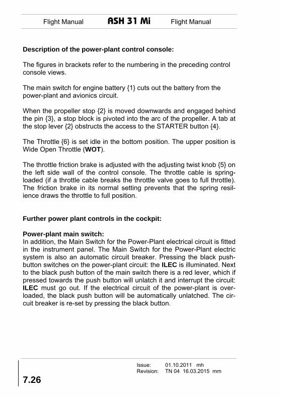
Description of the power-plant control console: The figures in brackets refer to the numbering in the preceding control console views. The main switch for engine battery {1} cuts out the battery from the power-plant and avionics circuit. When the propeller stop {2} is moved downwards and engaged behind the pin {3}, a stop block is pivoted into the arc of the propeller. A tab at the stop lever {2} obstructs the access to the STARTER button {4}. The Throttle {6} is set idle in the bottom position. The upper position is Wide Open Throttle (WOT). The throttle friction brake is adjusted with the adjusting twist knob {5} on the left side wall of the control console. The throttle cable is spring-loaded (if a throttle cable breaks the throttle valve goes to full throttle). The friction brake in its normal setting prevents that the spring resil-ience draws the throttle to full position. Further power plant controls in the cockpit: Power-plant main switch: In addition, the Main Switch for the Power-Plant electrical circuit is fitted in the instrument panel. The Main Switch for the Power-Plant electric system is also an automatic circuit breaker. Pressing the black push-button switches on the power-plant circuit: the ILEC is illuminated. Next to the black push button of the main switch there is a red lever, which if pressed towards the push button will unlatch it and interrupt the circuit: ILEC must go out. If the electrical circuit of the power-plant is over-loaded, the black push button will be automatically unlatched. The cir-cuit breaker is re-set by pressing the black button.
Issue: 01.10.2011 mh Revision: TN 04 16.03.2015 mm
7.26

Flight Manual ASH 31 Mi Flight Manual
Fuel valve: The fuel valve is next to the seat pan on the left cockpit wall.
In the forward position the fuel valve is open. Rear position is shut.
CAUTION: Prior to attempting to start the engine the position of the
fuel valve has to be checked and where necessary moved to its foremost position.
Fire warning light: A temperature sensor is fitted in the engine compartment which triggers the fire warning at a temperature above 140 °C (284 °F). The fire warn-ing is a red blinking diode in the instrument panel with the following placard:
If a fire warning is given, proceed as per 3.8 in Section 3 "Emergency Procedures". Rear View Mirror for propeller setting: This mirror is fitted on the front instrument panel cover or in the instru-ment panel on the right within the view of the pilot. By means of this mirror, the vertical position of the propeller must be checked prior to retracting it. Switch for fuel pump 2: As the fuel pumps consume a relatively large amount of current for producing a fuel pressure of minimum 3 bar (43.5 psi), the engine start procedure should be carried out with only one active fuel pump. For
Issue: 01.10.2011 mh. Revision: TN 04 16.03.2015 mm
7.27

Flight Manual ASH 31 Mi Flight Manual
this reason the fuel pump 2 is activated only temporarily with this switch during take-off until a safe height is reached. The pump is activated if both the ignition switch and the switch "Fuel Pump 2" are "ON". NOTE: When the fuel pump 2 is constantly on, the charging
current of the generator is just not sufficient to keep the battery voltage constant for a longer time. As a conse-quence the generator warning light at the ILEC control unit will go on; this may happen generally also if the battery voltage is too low.
7.10 Fuel and Oil Tank System See also Fig.7.10-2 at the end of this Section. The fuel system consists of a fuselage tank, mounted in the wheel well, with a fuel capacity for about 1 hour of engine operation. The ASH 31 Mi can also be optionally delivered with one or two fuel tank(s) fitted in the wings. The fuel drainer is located at the rear end of the left fuselage tank and is easily accessible when the landing gear is down. The fuel tank vent is fitted on the left-hand side of the fin, above the tail wheel. The vent of the wing tank is linked back into the fuselage tank. The tank for the oil loss lubrication is fitted in the engine compartment between engine block and exhaust silencer and is accessible when the propeller is extended. WARNING: The rotary engine uses an oil loss lubrication system. If
no oil is refilled into the oil tank or if the oil supply is in-terrupted, this will inevitably destroy the engine.
Issue: 01.10.2011 mh Revision: TN 04 16.03.2015 mm
7.28

Flight Manual ASH 31 Mi Flight Manual
The oil consumption has to be checked. The following reference values are given for this purpose (consumption depends on rpm):
a) 0.21 litre oil/h (7.1 ounces/h) at revolutions of about 7100 rpm b) 0.23 litre oil/h (7.8 ounces/h) at revolutions of about 7750 rpm c) or a bit more than 0.015 Litre (0.51 ounces) oil per 1 litre of fuel.
(1) Fuel Filling Systems Filling of the fuel tanks in fuselage and wings must be carried out only by means of the standard fuel refilling equipment. The electric refuelling equipment mainly comprises the fuel hose connectors, a fuel pump with electrical plug, a fuel filter and a hose, which is inserted into a fuel con-tainer when filling-up. The electrical plug fits the socket mounted in the instrument panel for this purpose. The ASH 31 Mi can be equipped with an on board refuelling system as an optional extra. For further details please refer to (4) below. (2) Filling of Fuselage and Wing Fuel Tanks The fuel hoses of the tanks may only be connected with the filling sys-tem outside the fuselage - the fuel hoses are long enough. This pre-vents fuel from dripping into the fuselage.
Issue: 01.10.2011 mh. Revision: TN 04 16.03.2015 mm
7.29

Flight Manual ASH 31 Mi Flight Manual
Filling the Fuselage Tank: Connect the external fuel refilling equipment with the fuel hose which is located in the baggage compartment in front of the spar and leading to the fuselage tank. Plug the electric connector of the fuel pump into the socket of the instrument panel. After all connections have been done activate the switch next to the socket. When filling the fuselage tank, monitor the fuel level indicator and switch off the electric filling system at the latest when 16 litres are indi-cated. When equipped additionally with fuel tanks in the wing: Prior to switching on the external refilling equipment the Tank Selector Switch [13] to the right of the ILEC engine control unit needs to be switched to „ON“. This will open the solenoid valve and allows the flow of fuel into the fuselage tank (refer to figure 7.10-2). CAUTION: Disconnect the wing tanks prior to refuelling the fuse-
lage tank in order to only fill fuel from the refilling equipment into the fuselage tank and not inadvertently fuel from the wing tanks as well. The vent line always remains connected.
After refuelling the fuselage tank turn the Tank Selector Switch back to „OFF“ in order to close the solenoid valve and to avoid unintentional drainage of wing fuel and overfilling the fuselage tank. This amount of fuel would be drained and lost through the fuselage tank vent. Filling the Wing Tanks: The optional wing tanks are not only interconnected by the refuelling connectors located in the baggage compartment in front of the main spar but also with the fuselage tank. These connectors are fuel tight, even when disconnecting them from full fuel tanks. For refuelling a wing tank place the fuel hose outside of the glider -the fuel hose is suffi-ciently long - and connect it to the refilling system.
Issue: 01.10.2011 mh Revision: TN 04 16.03.2015 mm
7.30

Flight Manual ASH 31 Mi Flight Manual
Plug the electric connector of the fuel pump into the socket of the in-strument panel. After all connections have been done activate the switch next to the socket. WARNING: The vent for the flexible wing tanks must be connected
while rigging regardless whether the wing tanks are in use or not.
CAUTION: Filling of fuel may only be carried out either by means
of the standard external electric refilling equipment or by means of the optional internal fuel filling system. More powerful pumps could burst the wing shell while filling the wing tanks! The fuel filter in the filling hose must not be removed.
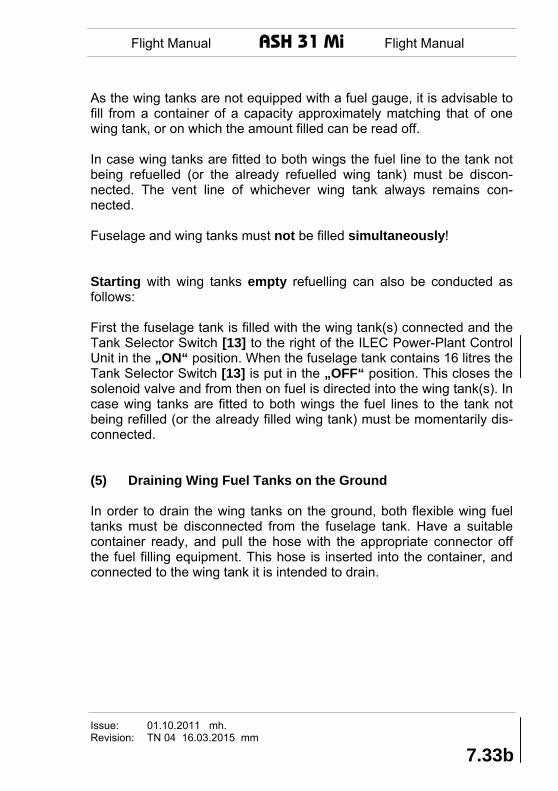
As the wing tanks are not equipped with a fuel gauge, it is advisable to fill from a container of a capacity approximately matching that of one wing tank, or on which the amount filled can be read off. Level the wings during filling. Fuselage and wing tanks must not be filled simultaneously! When fuelling has been completed, the filling equipment is discon-nected and the wing tanks are re-connected with the fuselage tank. Now verify in any case that the Tank Selector Switch [13] to the right of the ILEC control unit is re-set to position "OFF". If it remains in position "ON", fuel from the wing tank(s) would be fed into the fuselage tank and then overflow through the tank vent.
Issue: 01.10.2011 mh. Revision: TN 04 16.03.2015 mm
7.31

Flight Manual ASH 31 Mi Flight Manual
(3) Filling the Fuselage Tank in Flight The engine is fed with fuel exclusively by the fuselage tank. The wing tanks merely serve to refuel the fuselage tank. If, therefore, the fuselage tank is to be refuelled with fuel from the wing tanks in flight, the magnetic valve of the wing tanks must be opened with the Tank Selector Switch [13] to the right of the ILEC control unit (switch must be set to "ON" or "Autom."). The blinking yellow Tank LED [14] signals that the solenoid valve is open. In the switch position “Autom.“ the solenoid valve will open automatically if there are at least 6 liters of fuel in the fuselage tank. When the fuel level in the fuel tank reaches 12 liters the solenoid valve automatically closes and the Tank LED [14] goes out. WARNING: With the switch in position "ON" care should be taken
to close the wing tanks again in good time in order to prevent the fuselage tank being overfilled, causing fuel to be lost by overflowing through the tank vent. Monitor fuel level indicator!
CAUTION: It is recommended to use the Tank Selector Switch [13]
only in setting "Autom." because this makes it less likely that the fuselage tank will be overfilled. In any case, the fuel level indicator must always be monitored!
(4) Optional internal refilling system: As an optional extra the external refilling system can be permanently integrated into the fuselage. The refuelling pump is then located below the two fuel pumps for the engine between undercarriage and fire wall. The hose of the intake side runs to the barograph compartment where it can be connected to the fuel container via a fuel filter integrated into the refuelling hose. The pressure side of the pump is connected to the fuel line between solenoid valve and wing tank connection (see Fig. 7.10-1).
Issue: 01.10.2011 mh Revision: TN 04 16.03.2015 mm
7.32

Flight Manual ASH 31 Mi Flight Manual
The ASH 31 Mi can also be optionally equipped with an automatic shut off feature for the permanently installed refilling system. This prevents accidental overfilling of the fuselage fuel tank. This is accomplished by means of a sensor in the expansion tank which shuts off the re-fueling system when the fuselage tank is full. Procedures which are altered because of the installation of the auto-matic shut-off system are described below inside this boxes.
Filling the Fuselage Tank: The refilling system is activated via the switch on the instrument panel. When filling the fuselage tank, monitor the fuel level indicator and switch off the electric filling system at the latest when 16 litres are indi-cated. With the automatic fuel filling shut-off system The fuel re-filling system switch located in the instrument panel (don’t confuse this with the fuel tank selection switch beside the ILEC Power-Plant Control Unit) has three settings:
OFF: Fuel re-filling system is switched off AUTOMATIC: The fuel re-filling system is active and will be automati-
cally shut off when the fuselage tank is full Manual: The automatic shut-off feature will be de-activated and
the re-filling process must be accomplished manually. Refilling with optional wing tanks installed: When refuelling the optional wing tanks with the external refilling sys-tem it is necessary to select additionally „ON“ on the Tank Selector Switch [13] to the right of the ILEC Power-Plant Control Unit. This opens the solenoid valve and allows the fuel to flow into the fuselage tank. (see Fig. 7.10-1). CAUTION: Disconnect the wing tanks prior to refuelling
the fuselage tank in order to only fill up fuel from the refilling equipment into the fuselage tank and not inadvertently fuel from the wing
Issue: 01.10.2011 mh. Revision: TN 04 16.03.2015 mm
7.33

Flight Manual ASH 31 Mi Flight Manual
7.34
tanks as well. The vent line always remains connected.
After refuelling the fuselage tank turn the Tank Selector Switch back to „OFF“ in order to close the solenoid valve and to prevent drainage of wing fuel and overfilling the fuselage tank. This amount of fuel would be drained and lost through the fuselage tank vent. Filling the Wing Tanks: The optional wing tanks are not only interconnected by the refuelling connectors located in the baggage compartment in front of the main spar but also with the fuselage tank. The Tank Selector Switch [13] to the right of the ILEC Power-Plant Control Unit has to be in position „OFF“ to close the solenoid valve and prevent fuel draining inadvertently into the fuselage tank. The re-filling system is activated via a switch on the instrument panel. Ensure that the wings are kept level during refuelling. With automatic shutting off of the fuel re-filling system The fuel re-filling system switch in the instrument panel can be set to “AUTOMATIC” or “MANUAL”. However, the shut off feature does not function when re-filling the wing tanks. Consequently the amount of fuel being filled must be monitored in the usual manner.
Note: In case the fuel re-filling system has already been shut
off by the sensor while filling the fuselage tank, it is possible that when attempting to fuel the wing tanks, the fuel re-filling system can only be activated by setting the switch to “MANUAL”.
Issue: 01.10.2011 mh Revision: TN 04 16.03.2015 mm
7.33a
Flight Manual ASH 31 Mi Flight Manual
7.35
As the wing tanks are not equipped with a fuel gauge, it is advisable to fill from a container of a capacity approximately matching that of one wing tank, or on which the amount filled can be read off. In case wing tanks are fitted to both wings the fuel line to the tank not being refuelled (or the already refuelled wing tank) must be discon-nected. The vent line of whichever wing tank always remains con-nected. Fuselage and wing tanks must not be filled simultaneously! Starting with wing tanks empty refuelling can also be conducted as follows: First the fuselage tank is filled with the wing tank(s) connected and the Tank Selector Switch [13] to the right of the ILEC Power-Plant Control Unit in the „ON“ position. When the fuselage tank contains 16 litres the Tank Selector Switch [13] is put in the „OFF“ position. This closes the solenoid valve and from then on fuel is directed into the wing tank(s). In case wing tanks are fitted to both wings the fuel lines to the tank not being refilled (or the already filled wing tank) must be momentarily dis-connected. (5) Draining Wing Fuel Tanks on the Ground In order to drain the wing tanks on the ground, both flexible wing fuel tanks must be disconnected from the fuselage tank. Have a suitable container ready, and pull the hose with the appropriate connector off the fuel filling equipment. This hose is inserted into the container, and connected to the wing tank it is intended to drain.
Issue: 01.10.2011 mh. Revision: TN 04 16.03.2015 mm
7.33b

Flight Manual ASH 31 Mi Flight Manual
Empty Page
Issue: 01.10.2011 mh Revision: TN 04 16.03.2015 mm
7.367.33c

Flight Manual ASH 31 Mi Flight Manual
Sw
itch
setti
ng „O
FF“
Sol
enoi
d va
lve
is c
lose
d,
Win
g ta
nk is
refu
elle
d S
witc
h se
tting
„ON
“ S
olen
oid
valv
e is
ope
n,
Fuse
lage
tank
is re
fuel
led
Setti
ng o
f the
Tan
k Se
lect
or S
witc
h
Fig. 7.10-1 Internal Refilling System
Issue: 01.10.2011 mh. Revision: TN 04 16.03.2015 mm
7.377.33d

Flight Manual ASH 31 Mi Flight Manual
7.11 Electrical System Refer also to Fig 7.11-1 and 7.11-2 at the end of this Section. (1) Soaring Flight On-Board Circuit The electrical system is supplied by a 12V battery. A main switch {1} is installed in the power-plant control console which is turning on the board system. Each electrical appliance is protected by its own fuse. There are different possible configurations to supply the electrical on-board system. Refer also to Fig.7.11-1. (2) Power-Plant Current Supply The power-plant circuit is fused through the Power-Plant Main Switch. Only the engine battery is being charged during powered flight. It is depending on the charge of the engine battery whether the propel-ler can be extended or retracted.
Issue: 01.10.2011 mh Revision:
7.34

Maintenance Manual ASH 31 Mi Maintenance Manual
Fuselage Length 7.10 m (23.29 ft)Height (Fin and Tail Wheel) 1.505 m (4.93 ft)Cockpit width 0.66 m (2.16 ft)Cockpit hight 0.877 m (2.87 ft) Vertical Tail (fin) Surface area 1.064 m² (11.45 sqft)Airfoil section DU 86-131/30 Rudder Airfoil section 0.352 m² (3.78 sqft) Horizontal Tail Span 2.850 m (9.35 ft)Surface area 0.988 m² (10.63 sqft)Aspect ratio 7.644 Airfoil section DU 92-131/25 Elevator Surface area 0.232 m² (2.49 sqft) Winglet Height 0,50 m (1,64 ft)Surface area (one winglet) 0,071 m² (0,76 sqft)Aspect ratio 3.52 Sweep back of leading edge 30° Airfoil DU 99-125 Airbrake Blades (Schempp-Hirth-type, top surface only) Length 1.40 m (4.59 ft)Surface area (both together) 0.355 m² (3.82 sqft)Max. height above wing top surface 0.13 m (0.42 ft)
Issue: 01.10.2011 mh / mm Revision:
1.5

Maintenance Manual ASH 31 Mi Maintenance Manual
Power-Plant Engine: IAE 50R-AA Max. power, take-off: 37.3 kW (3 minute limit) 7750 rpm Max. cont. power: 35.8 kW 7100 rpm Max. take-off revs: 7750 rpm Max. continuous revs: 7100 rpm Max. overspeed revs (20 sec.): 8000 rpm Min. idle revs: 2800 rpm
Max. coolant temp., take-off: 90 °C (194°F) Min. coolant temp., take-off: 40 °C (104°F) Max. coolant temp., continuous: 100 °C (212°F) Max. rotor cooling air temp.: 130 °C (266°F) Note: The above stated take-off performance refers to the minimum
value as given in the engine data sheet. A nominal perform-ance of 41 kW is typical on the other hand.
Lubrication: Total loss oil lubrication at ratio: 1:60 approx. Oil and fuel grades: see Flight Manual Section 2.12 Transmission: Toothed belt transmission with 1:2.78 reduction ratio. The following types of propeller are approved: Manufacturer: Alexander Schleicher GmbH & Co. Propeller: AS2F1-1/R153-92-N1
Issue: 01.10.2011 mh / mm Revision: TN 04 / 05 01.04.2015 mm
1.6

Maintenance Manual ASH 31 Mi Maintenance Manual
Issue: 01.10.2011 mh / mm Revision:
2.85
Fig. 2.8-2 Page 3 of 6 ECU Circuit Diagram

Maintenance Manual ASH 31 Mi Maintenance Manual
Fig. 2.8-2 Page 4 of 6
Regulator wiring diagramif two-wire alternator is used
Ducati BOR 0153
Alternator≈
yello
w
yello
w
red
whi
te
blac
k
red
+
-
1 2Diode 600V 25A
Circuitbreaker
15 A
22000µF40-65 V
ILEC Pin Assignment
Pin DSUB 25-polig Pin DSUB 9-polig 1 ECU-Error 1 Ignition 1 2 2 Ignition +12V 3 3 Current fuel consumption 4 Propeller retract, Signal 4 5 5 6 Solenoid valve wing fuel tank 6 Ignition 2 7 7 Temperature Air Cooling 8 RPM 8 9 5V Tank signal (orange) 9 Fuel pump 1
10 Limit switch "extended" 11 Fuel pressure 12 Oil level sensor 13 Earth 14 15 Temperature Liquid Coolant 16 Starter relay 17 Propeller extend, Signal 18 Fuel pump 2 19 Buzzer 20 21 Starter 22 Tank signal (purple) 23 Limit switch "retracted" 24 25 12V Input
Issue: 01.10.2011 mh / mm Revision: TN 04 16.03.2015 mm
2.86

Maintenance Manual ASH 31 Mi Maintenance Manual
Manufacturer Type Data Sheet Spec. No.
Measuring Range Ref. No.
Power-Plant Instrument
ILEC
Engine Control Unit, Type MCU ASH 31 Mi
Compass
Air path C 2300 - - -
Büscher KP.010 KP.013
- -
- -
- -
Ludolph
FK 5 FK 16 FK 16/83B FK 16/83S FK 16/83SB
10.410/1 10.410/3 10.410/7 10.410/7 10.410/7
- - - - -
- - - - -
PZL BS 1 B 13/KJ KI 13A
- - -
- - -
- - -
Schanz SK 75 SK 80
- -
- -
- S7039
Precision Aviation
PAI-700-14 - - -
Hamilton H I 400 TSO C7c Tp1 - - Bohli 46-MFK-1 not approved, only as secondary equipment
Issue: 01.10.2011 mh / mm Revision: TN 04 16.03.2015 mm
12.5
Maintenance Manual ASH 31 Mi Maintenance Manual
Manufacturer Type Data Sheet Spec. No.
Measuring Range Ref. No.
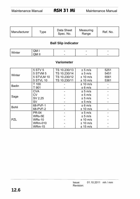
Ball Slip indicator
Winter QM I
QM II - -
- -
- -
Variometer
Winter
5 STV 5 5 STVM 5 5 STVLM 10 5 STVL 10
TS 10.230/13 TS 10.230/14 TS 10.230/12 TS 10.230/11
± 5 m/s ± 5 m/s
± 10 m/s ± 10 m/s
5251 5451 5561 5361
Badin T 100 T 901
- -
± 10 m/s ± 6 m/s
- -
Sage
CVA CV SV 2.25 SV
- - - -
± 5 m/s ± 5 m/s ± 5 m/s ± 5 m/s
- - - -
Bohli 68-PVF-1 68-PVF-2
- -
± 6 m/s ± 10 m/s
-
PZL
PR-04 WRs-5E WRs-10 WRm-010 WRm-15
- - - - -
± 5 m/s ± 5 m/s
± 10 m/s ± 10 m/s ± 15 m/s
- - - - -
Issue: 01.10.2011 mh / mm Revision:
12.6

Maintenance Manual ASH 31 Mi Maintenance Manual
Issue: 01.10.2011 mh / mm Revision: TN 04 16.03.2015 mm
Fig. 2.4-1 Fuel System
2.73

Maintenance Manual ASH 31 Mi Maintenance Manual
Revision: TN 04 16.03.2015 mm
Fig. 2.4-1-1 Circuit Diagram "Automatically shut off refuelling system"
Issue: 01.10.2011 mh / mm
2.74

Maintenance Manual ASH 31 Mi Maintenance Manual
Issue: 01.10.2011 mh / mm Revision: TN 04 16.03.2015 mm
Fig. 2.8-2 Page 1 of 6 Engine Circuit Diagram
2.83