flht front end lowering kit - hdonlineshop.de ... 2 1 is00154 1. vise grip 2. rubber pad 3. plastic...
TRANSCRIPT

-J02546 REV. 2007-11-30
FLHT FRONT END LOWERING KIT
GENERALKit Number
54628-06
Models
For model fitment information, please see the P&A Retail Cat-alog or the Parts and Accessories section of www.harley-davidson.com (English only).
Additional Parts Required
This kit is not designed to be used with Sidecar installed.Any attempt to use this front suspension kit with sidecarcan adversly affect stability and handling. (00430b)
This Front End Lowering Kit cannot be used independently.It must be used with an appropriate Low Rear SuspensionKit or handling and cornering can be affected, which coulddistract the rider, causing loss of control and death orserious injury. (00429b)
Proper installation of this kit also requires the following specialtools: Fork Tube Holder (HD-41177), Fork Seal/Bushing Tool(HD-34634), Front Fork Oil Level Gauge (HD-59000B) andFok Spring Compressing Tool (HD-45966).
Proper installation of this kit may also requires the replacementof the following parts:
Table 1. Replacement Parts
PartNumber
Item (Quantity)
45845-77O-ring (2)
45733-48Quad ring seal (2)
45866-84Fork tube bushing (2)
45859-77AWear ring
45940-84Slider bushing (2)
45875-84AFork oil seal (2)
45405-75AScrew with copper crush washer, 6 mm (2)
99884-80Harley-Davdison® Fork oil
The rider's safety depends upon the correct installationof this kit. Use the appropriate service manual procedures.If the procedure is not within your capabilities or you donot have the correct tools, have a Harley-Davidson dealerperform the installation. Improper installation of this kitcould result in death or serious injury. (00333a)
NOTE
This instruction sheet references Service Manual information.A Service Manual for your model motorcycle is required forthis installation and is available from a Harley-Davidson Dealer.
Kit Contents
See Figure 10 and Table 2.
1
2
3
is04971
1. Fork cap bolt2. Fork stop3. Pinch bolt
Figure 1. Loosen Pinch Bolt on Lower Fork Bracket
-J02546 1 of 9
Ro
stoc
k n.e. Germany
w
ww.h donlinesho
p.d
e
3
2
1
is00154
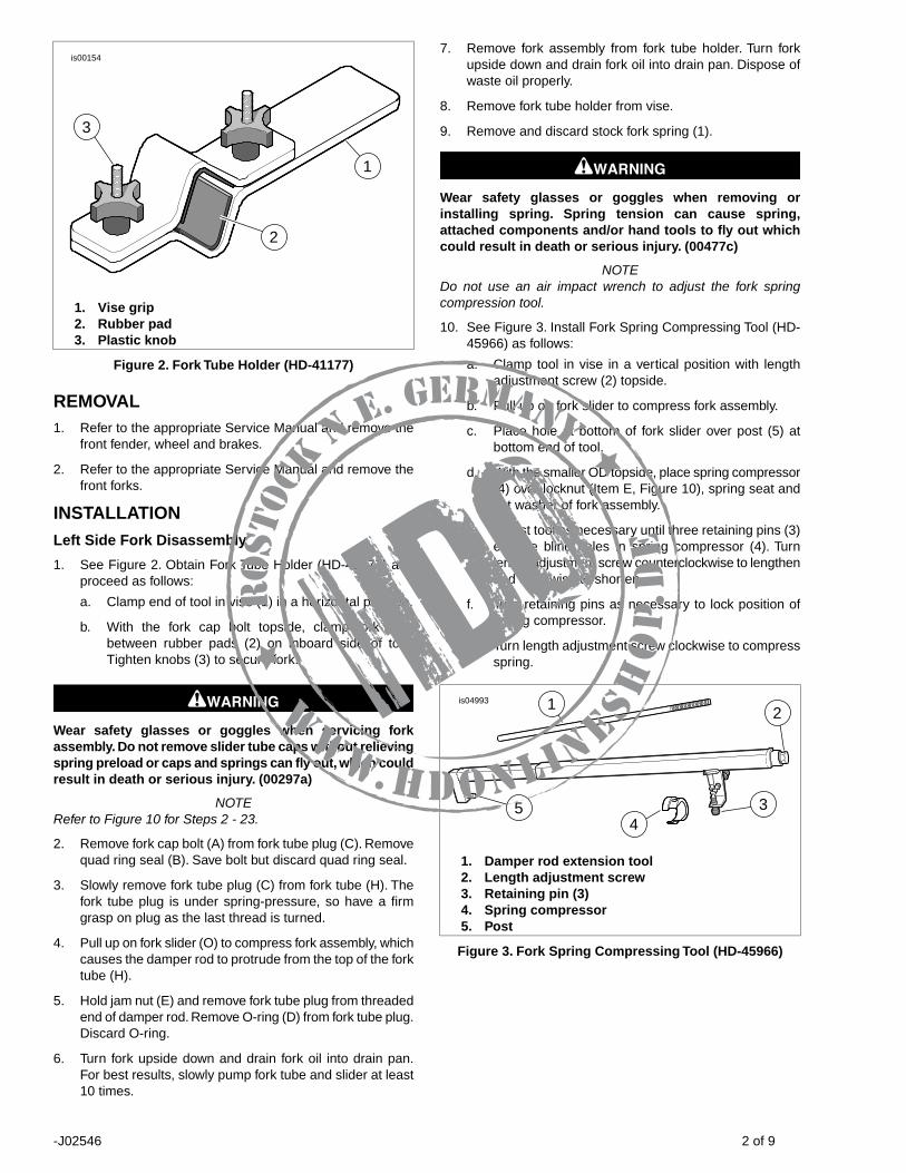
1. Vise grip2. Rubber pad3. Plastic knob
Figure 2. Fork Tube Holder (HD-41177)
REMOVAL1. Refer to the appropriate Service Manual and remove the
front fender, wheel and brakes.
2. Refer to the appropriate Service Manual and remove thefront forks.
INSTALLATIONLeft Side Fork Disassembly
1. See Figure 2. Obtain Fork Tube Holder (HD-41177) andproceed as follows:
a. Clamp end of tool in vise (1) in a horizontal position.
b. With the fork cap bolt topside, clamp fork tubebetween rubber pads (2) on inboard side of tool.Tighten knobs (3) to secure fork.
Wear safety glasses or goggles when servicing forkassembly. Do not remove slider tube caps without relievingspring preload or caps and springs can fly out, which couldresult in death or serious injury. (00297a)
NOTERefer to Figure 10 for Steps 2 - 23.
2. Remove fork cap bolt (A) from fork tube plug (C). Removequad ring seal (B). Save bolt but discard quad ring seal.
3. Slowly remove fork tube plug (C) from fork tube (H). Thefork tube plug is under spring-pressure, so have a firmgrasp on plug as the last thread is turned.
4. Pull up on fork slider (O) to compress fork assembly, whichcauses the damper rod to protrude from the top of the forktube (H).
5. Hold jam nut (E) and remove fork tube plug from threadedend of damper rod. Remove O-ring (D) from fork tube plug.Discard O-ring.
6. Turn fork upside down and drain fork oil into drain pan.For best results, slowly pump fork tube and slider at least10 times.
7. Remove fork assembly from fork tube holder. Turn forkupside down and drain fork oil into drain pan. Dispose ofwaste oil properly.
8. Remove fork tube holder from vise.
9. Remove and discard stock fork spring (1).
Wear safety glasses or goggles when removing orinstalling spring. Spring tension can cause spring,attached components and/or hand tools to fly out whichcould result in death or serious injury. (00477c)
NOTEDo not use an air impact wrench to adjust the fork springcompression tool.
10. See Figure 3. Install Fork Spring Compressing Tool (HD-45966) as follows:
a. Clamp tool in vise in a vertical position with lengthadjustment screw (2) topside.
b. Pull up on fork slider to compress fork assembly.
c. Place hole at bottom of fork slider over post (5) atbottom end of tool.
d. With the smaller OD topside, place spring compressor(4) over locknut (Item E, Figure 10), spring seat andflat washer of fork assembly.
e. Adjust tool as necessary until three retaining pins (3)engage blind holes in spring compressor (4). Turnlength adjustment screw counterclockwise to lengthenand clockwise to shorten.
f. Turn retaining pins as necessary to lock position ofspring compressor.
g. Turn length adjustment screw clockwise to compressspring.
1
34
5
2is04993
1. Damper rod extension tool2. Length adjustment screw3. Retaining pin (3)4. Spring compressor5. Post
Figure 3. Fork Spring Compressing Tool (HD-45966)
-J02546 2 of 9
Ro
stoc
k n.e. Germany
w
ww.h donlinesho
p.d
e
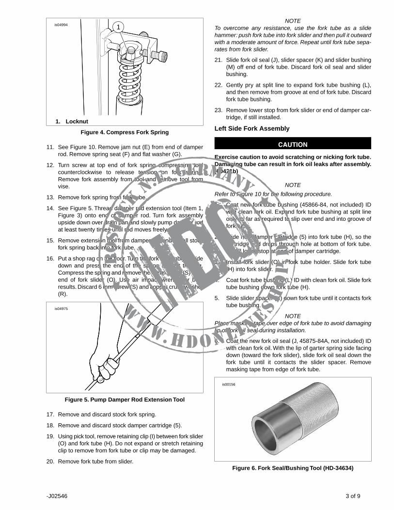
1is04994
1. Locknut
Figure 4. Compress Fork Spring
11. See Figure 10. Remove jam nut (E) from end of damperrod. Remove spring seat (F) and flat washer (G).
12. Turn screw at top end of fork spring compressing toolcounterclockwise to release tension on fork spring.Remove fork assembly from tool and remove tool fromvise.
13. Remove fork spring from fork tube.
14. See Figure 5. Thread damper rod extension tool (Item 1,Figure 3) onto end of damper rod. Turn fork assemblyupside down over drain pan and slowly pump damper rodat least twenty times until rod moves freely.
15. Remove extension tool from damper rod and install stockfork spring back into fork tube.
16. Put a shop rag on the floor.Turn the fork assembly upsidedown and press the end of the spring against the rag.Compress the spring and remove the 6 mm screw (S) fromend of fork slider (O). Use air impact wrench for bestresults. Discard 6 mm screw (S) and copper crush washer(R).
is04975
Figure 5. Pump Damper Rod Extension Tool
17. Remove and discard stock fork spring.
18. Remove and discard stock damper cartridge (5).
19. Using pick tool, remove retaining clip (I) between fork slider(O) and fork tube (H). Do not expand or stretch retainingclip to remove from fork tube or clip may be damaged.
20. Remove fork tube from slider.
NOTETo overcome any resistance, use the fork tube as a slidehammer: push fork tube into fork slider and then pull it outwardwith a moderate amount of force. Repeat until fork tube sepa-rates from fork slider.
21. Slide fork oil seal (J), slider spacer (K) and slider bushing(M) off end of fork tube. Discard fork oil seal and sliderbushing.
22. Gently pry at split line to expand fork tube bushing (L),and then remove from groove at end of fork tube. Discardfork tube bushing.
23. Remove lower stop from fork slider or end of damper car-tridge, if still installed.
Left Side Fork Assembly
Exercise caution to avoid scratching or nicking fork tube.Damaging tube can result in fork oil leaks after assembly.(00421b)
NOTE
Refer to Figure 10 for the following procedure.
1. Coat new fork tube bushing (45866-84, not included) IDwith clean fork oil. Expand fork tube bushing at split lineonly as far as required to slip over end and into groove offork tube.
2. Slide new damper cartridge (5) into fork tube (H), so thecartridge end drops through hole at bottom of fork tube.Install lower stop at end of damper cartridge.
3. Install fork slider (O) in fork tube holder. Slide fork tube(H) into fork slider.
4. Coat fork tube bushing (L) ID with clean fork oil. Slide forktube bushing down fork tube (H).
5. Slide slider spacer (K) down fork tube until it contacts forktube bushing.
NOTEPlace masking tape over edge of fork tube to avoid damaginglip of fork oil seal during installation.
6. Coat the new fork oil seal (J, 45875-84A, not included) IDwith clean fork oil. With the lip of garter spring side facingdown (toward the fork slider), slide fork oil seal down thefork tube until it contacts the slider spacer. Removemasking tape from edge of fork tube.
is00156
Figure 6. Fork Seal/Bushing Tool (HD-34634)
-J02546 3 of 9
Ro
stoc
k n.e. Germany
w
ww.h donlinesho
p.d
e

is00157
Figure 7. Install Fork Oil Seal
7. See Figure 6. Obtain the Fork Seal/Bushing Tool (HD-34634) and proceed as follows:
a. Slide the fork seal installer down the fork tube until itcontacts the fork oil seal.
b. See Figure 7. Using the tool like a slide hammer, drivefork oil seal (with slider spacer and guide bushing)down the fork tube until retaining clip groove is visiblein fork slider ID.
c. Slide the retaining clip (I) down the fork tube until itcontacts the fork oil seal. Install retaining clip in thefork slider groove. Do not expand or stretch retainingclip to install on fork tube or clip may be damaged.
NOTEEnsure the fork spring is installed with dense section of coilsto the bottom.
8. Obtain shorter fork spring (1) from the kit. Install new forkspring into fork tube.
9. Remove fork assembly from fork tube holder.
10. Place a shop rag on the floor, and turning fork assemblyupside down, press end of spring against rag.
11. Install new screw (S) with copper crush washer (R, 45405-75A, not included). Slide screw through hole at bottom offork slider and start into end of damper cartridge.
12. Compress spring to prevent rotation of damper cartridgeand tighten the screw to 11-18 ft-lbs (15-24 Nm).
13. Remove fork spring from fork tube.
14. With the fork tube topside, clamp fork slider (not the forktube) into fork tube holder.
NOTEInstall the drain screw at the bottom of the fork slider, ifremoved. Tighten the screw to 72-96 in-lbs (8-11 Nm).
15. Fill the fork tube as follows:
a. Thread jam nut onto damper rod until it fully seats onshoulder.
b. See Figure 5. Thread extension tool onto end ofdamper rod.
c. Pour 5 ounces (147.9 ml) of Harley-Davidson TypeE Fork Oil into the fork tube.
d. Slowly pump the damper rod until resistance is feltand then pump five more times.
e. Place the damper rod in the fully bottomed position.
f. Pour another 6 ounces (177.5 ml) of fork oil into thefork tube.
g. Remove the extension tool from the end of thedamper rod.
is00158
Figure 8. Front Fork Oil Level Gauge (HD-59000B)
is00159
Figure 9. Remove Excess Fork Oil
Incorrect amount of fork oil can adversely affect handlingand lead to loss of vehicle control, which could result indeath or serious injury. (00298a)
-J02546 4 of 9
Ro
stoc
k n.e. Germany
w
ww.h donlinesho
p.d
e

16. Adjust the fork oil level, so that it is 6.14 inches (156 mm)from the top of the fork tube with the fork tube compressedand the fork spring removed. Proceed as follows:
a. See Figure 8. Obtain the Front Fork Oil Level Gauge(HD-59000B).
b. Loosen thumbscrew on metal ring and move it up ordown the rod until the bottom of the ring is 6.14 inches(156 mm) from the bottom of the rod. Tighten thumb-screw.
c. Push the handle on the cylinder all the way in.
d. See Figure 9. Insert rod into top of fork tube untilmetal ring rests flat on top of fork tube.
e. Pull handle to remove fork oil from fork tube. Observefork oil through transparent tube to ensure oil is beingdrawn from cylinder.
f. Remove rod from fork tube. Push handle into cylinderto eject excess fork oil into suitable container.
g. If necessary, repeat Steps 16(c) through 16(f). Levelis correct when no fork oil is observed being drawnthrough transparent tube.
17. Install fork spring into the fork tube with the dense enddown.
18. Pull up on fork slider to compress fork assembly, whichcauses the damper rod and spring to protrude from thetop of the fork tube.
19. Thread extension tool onto end of damper rod.
Wear safety glasses or goggles when removing orinstalling spring. Spring tension can cause spring,attached components and/or hand tools to fly out whichcould result in death or serious injury. (00477c)
NOTEDo not use an air impact wrench to adjust the fork springcompression tool.
20. See Figure 3. Install fork spring compression tool as fol-lows:
a. Clamp tool in vise in a vertical position with lengthadjustment screw (2) topside.
b. Pull up on fork slider to compress fork assembly.
c. Place hole at bottom of fork slider over post (5) atbottom end of tool.
d. Place flat washer (Item G, Figure 10), rounded sideup, over the damper rod extension tool and on top ofspring. Place spring seat (Item F, Figure 10), concaveside up, on top of the flat washer. With the smallerOD topside, place spring compressor (4) over springseat and flat washer.
e. Adjust tool as necessary until three retaining pins (3)engage blind holes in spring compressor (4). Turnlength adjustment screw counterclockwise to lengthenand clockwise to shorten.
f. Turn retaining pins as necessary to lock position ofspring compressor.
g. Turn length adjustment screw in a clockwise directionto compress spring.
21. After a number of turns, pull up on extension tool to raisedamper rod. If threaded portion of rod cannot be pulledcompletely out of spring, compress spring further. Repeatuntil threaded portion of rod can can be pulled completelyout of spring.
22. Remove extension tool, while holding the damper rod.
23. Thread locknut (E) onto the damper rod until it contactsthe shoulder.
24. Install new O-ring (D, 45845-77, not included) onto forktube plug. Thread fork tube plug onto threaded end of roduntil it bottoms. Turn jam nut counterclockwise until itmakes firm contact with the fork tube plug. Tighten jamnut to 13-20 ft-lbs (18-27 Nm).
25. Turn the length adjustment screw at top end of fork springcompressing tool counterclockwise to release tension onfork spring. Loosen retaining pins and remove springcompressor. Remove fork assembly from tool and removetool from vise.
26. Install fork tube holder in vise. Clamp fork tube into forktube holder.
NOTEDo NOT overtighten or O-ring damage may occur.
27. Thread fork tube plug (C) into fork tube. Tighten fork tubeplug to 22-59 ft-lbs (30-79 Nm).
28. Install new quad ring seal (B, 45733-48, not included) ontofork cap bolt. Thread fork cap bolt (A) into fork tube plugto prevent loss of fork oil while handling.
29. Remove the fork assembly from the fork tube holder.
Right Side Fork Disassembly
1. Obtain right fork assembly removed in earlier step.
2. Remove nuts, lockwashers, flat washers and axle holderfrom studs at end of fork slider.
-J02546 5 of 9
Ro
stoc
k n.e. Germany
w
ww.h donlinesho
p.d
e

3. See Figure 2. Install fork in Fork Tube Holder (HD-41177)as follows:
a. Clamp end of tool (1) in vise in a horizontal position.
b. With the fork cap bolt topside, clamp fork tubebetween rubber pads (2) on inboard side of tool.Tighten knobs (3) until fork tube is securely held.
Wear safety glasses or goggles when servicing forkassembly. Do not remove slider tube caps without relievingspring preload or caps and springs can fly out, which couldresult in death or serious injury. (00297a)
NOTERefer to Figure 10 for Steps 4 - 17.
4. Remove fork cap bolt (A) from fork tube plug. Removequad ring seal (B). Save bolt but discard quad ring seal.
5. Slowly remove fork tube plug (C) from fork tube (H). Beaware that fork tube plug is under spring-pressure, sohave a firm grasp on plug as the last thread is turned.
6. Pull up on fork slider (V) to compress fork assembly, whichcauses the damper rod to protrude from the top of the forktube (H).
7. Remove the fork spring (2) from the fork tube.
8. Remove fork assembly from fork tube holder. Turn forkupside down and drain fork oil into drain pan. For bestresults, slowly pump fork tube and slider at least 10 times.
9. Install fork spring back into fork tube.
10. Put a shop rag on the floor.Turn the fork assembly upsidedown and press the end of the spring against the rag.Compress the spring and remove the 6 mm screw (S) fromend of fork slider (V). Use air impact wrench for bestresults. Discard 6 mm screw (S) and copper crush washer(R).
11. Remove fork spring (2) and damper tube (3) from forktube. Discard fork spring.
12. Remove wear ring (T) and rebound spring (4) from dampertube. Save wear ring but discard rebound spring anddamper tube.
13. Using pick tool, remove retaining clip (I) between fork slider(V) and fork tube (H). Do not expand or stretch retainingclip to remove from fork tube or clip may be damaged.
NOTETo overcome any resistance, use the fork tube as a slidehammer: Push fork tube into fork slider and then pull it outwardwith a moderate amount of force. Repeat this sequence untilfork tube separates from fork slider.
14. Remove fork tube from fork slider.
15. Slide fork oil seal (J), slider spacer (K) and slider bushing(M) off end of fork tube. Discard fork oil seal and sliderbushing.
16. Gently pry at split line to expand fork tube bushing (L),and then remove from groove at end of fork tube. Discardfork tube bushing.
17. Remove the lower stop (U) from the fork slider.
Right Side Fork Assembly
Exercise caution to avoid scratching or nicking fork tube.Damaging tube can result in fork oil leaks after assembly.(00421b)
NOTE
Refer to Figure 10 for the following procedure.
1. Coat new fork tube bushing (45866-84, not included) IDwith clean fork oil. Expand fork tube bushing at split lineonly so far as required to slip over end and into groove offork tube.
2. Obtain new damper tube (3). If necessary, install new wearring (T, 45859-77A, not included) in groove at top of newdamper tube. Install new rebound spring (4) and install onopposite end of damper tube.
3. With the wear ring topside, slide new damper tube (3) intofork tube, so that tube end drops through hole at bottomof fork tube (H). Install lower stop (U) at end of dampertube.
4. Install fork slider (V) in fork tube holder. Slide fork tubeinto fork slider.
5. Coat slider bushing (M) ID with clean fork oil. Slide sliderbushing down fork tube.
6. Slide slider spacer (K) down fork tube until it contacts sliderbushing.
NOTEPlace masking tape over edge of fork tube to avoid damaginglip of fork oil seal during installation.
7. Coat the new fork oil seal (J, 45875-84A, not included) IDwith clean fork oil. With the lip of garter spring side facingdown (toward the fork slider), slide fork oil seal (J) downfork tube until it contacts the slider spacer. Removemasking tape from edge of fork tube.
8. See Figure 6. Obtain the Fork Seal/Bushing Tool (HD-34634) and proceed as follows:
a. Slide the fork seal installer down the fork tube until itcontacts the fork oil seal.
b. See Figure 7. Using the tool like a slide hammer, drivefork oil seal (with slider spacer and guide bushing)down the fork tube until retaining clip groove is visiblein fork slider ID.
c. Slide the retaining clip (I) down the fork tube until itcontacts the fork oil seal. Install retaining clip in thefork slider groove. Do not expand or stretch retainingclip to install on fork tube or clip may become bent ordistorted.
NOTEEnsure the fork spring is installed with dense section of coilsto the bottom.
9. Obtain longer fork spring (2). Install new fork spring intofork tube.
10. Remove fork assembly from fork tube holder.
-J02546 6 of 9
Ro
stoc
k n.e. Germany
w
ww.h donlinesho
p.d
e

11. Place a shop rag on the floor, turn fork assembly upsidedown and press end of spring against rag.
12. Install new screw (S) with copper crush washer (R, 45405-75A, not included). Slide screw through hole at bottom offork slider (V) and start into end of damper tube.
13. While compressing spring to prevent rotation of dampertube, tighten the screw to 11-18 ft-lbs (15-24 Nm).
14. Remove fork spring from fork tube.
15. With the fork tube topside, clamp fork slider (not the forktube) into fork tube holder.
NOTEInstall the drain screw at the bottom of the fork slider, ifremoved. Tighten the screw to 72-96 in-lbs (8-11 Nm).
16. Pour 11.1 ounces (328 ml) of Harley-Davidson Type EFork Oil into the fork tube.
17. Adjust the fork oil level, so that it is 4.92 inches (125 mm)from the top of the fork tube with the fork tube compressed,the main spring removed and the blow valve installed.Proceed as follows:
a. See Figure 8. Obtain the Front Fork Oil Level Gauge(Part Number HD-59000B).
b. Loosen thumbscrew on metal ring and move it up ordown the rod until the bottom of the ring is 4.92 inches(125 mm) from the bottom of the rod. Tighten thumb-screw.
c. Push the handle on the cylinder all the way in.
d. See Figure 9. Insert rod into top of fork tube untilmetal ring rests flat on top of fork tube.
e. Pull handle to remove fork oil from fork tube. Observefork oil through transparent tube to ensure oil is beingdrawn from cylinder.
f. Remove rod from fork tube. Push handle into cylinderto eject excess fork oil into suitable container. Disposeof waste properly.
g. If necessary, repeat Steps 17(c) through 17(f). Levelis correct when no fork oil is observed being drawnthrough transparent tube.
18. Install fork spring into the fork tube with the dense enddown.
NOTEDo NOT overtighten or O-ring damage may occur.
19. Install new O-ring (D, 45845-77, not included) onto forktube plug (B). Compressing fork spring with end of forktube plug, thread fork tube plug into fork tube.Tighten forktube plug to 22-59 ft-lbs (30-79 Nm).
Fork Installation
1. Remove fork cap bolt from front fork.
2. Refer to the appropriate Service Manual and install thefront forks.
After repairing the brake system, test brakes at low speed.If brakes are not operating properly, testing at high speedscan cause loss of control, which could result in death orserious injury. (00289a)
3. Refer to the appropriate Service Manual and install thefront fender, wheel and brakes.
-J02546 7 of 9
Ro
stoc
k n.e. Germany
w
ww.h donlinesho
p.d
e

SERVICE PARTS
5
1
2
3
4
A
C
E
G
B
C
D
F
H
I
K
M
O
J
L
N
A
D
B
T
I
J
L
U
K
M
HV
W
X
Y
ZR
S
P
QP
Q
R
S
is04976
Figure 10. Service Parts for Profile Low Front End Lowering Kit
Table 2. Service Parts Table
Part NumberDescription (Quantity)Item
54134-02Fork spring service kit
Not Sold Separately• Fork spring, left (short)1
Not Sold Separately• Fork spring, right (long)2
Not Sold Separately• Damper tube3
Not Sold Separately• Rebound spring4
46269-02Damper cartridge5
-J02546 8 of 9
Ro
stoc
k n.e. Germany
w
ww.h donlinesho
p.d
e

Table 2. Service Parts Table
Part NumberDescription (Quantity)Item
Items mentioned in text, but not included in kit:
Fork cap bolt (2)A
Quad ring seal (2)B
Fork tube plug (2)C
O-ring (2)D
Jam nutE
Spring seatF
Washer, flatG
Fork tube (2)H
Retaining clip (2)I
Fork oil seal (2)J
Slider spacer (2)K
Bushing, fork tube (2)L
Bushing, slider (2)M
Lower stopN
Fork slider, leftO
Washer, flat (2)P
Plug (2)Q
Washer, copper, crush (2)R
Screw, 6 mm (2)S
Wear ringT
Lower stopU
Fork slider, rightV
Axle holderW
Washer, flat (2)X
Lockwasher (2)Y
Nut (2)Z
-J02546 9 of 9
Ro
stoc
k n.e. Germany
w
ww.h donlinesho
p.d
e