flexoglobal tm 2008.pdf · be a good time to reconsider if the best methods for ink handling and...
TRANSCRIPT

• ColorPerception
• NewBenchmarkinPressPerformance
• DigitalFlexoDeliversCompetitiveEdge
• MinimumDotforPhotopolymerflexoDefined
• Viscosity,yourlastDollar
• PackagingDown
Under
...andmore!
Broughttoyouby
SalmonCreekPublishing
September2008
YourPortaltotheGlobalFlexographicIndustry
FlexoGlobalTM
FocusonTechnology

2 www.flexoglobal.com september2008FlexoGlobal
Features
FlexoGlobalTM
FlexoGlobalTM
FlexoGlobal’s e-magazine is brought to you by FlexoGlobal,
your portal to the global flexographic industry.
FlexoGlobal’s mission is to deliver to the global flexographic community topnotch technical
articles authored by industry experts, industry updates on an
international level, and overviews of business practices to improve
operating efficiencies.
Publisher & Editor-in-ChiefLaura Wayland-Smith Hatch
Volume 1 No. 3FlexoGlobal
Editorial, Advertising, & Circulation Office
Salmon Creek Publishing7580 Salmon Creek Road
Williamson, NY [email protected]
315.589-8879
Copyright © 2008 Salmon Creek Publishing.
All rights reserved. None of the materials in this publication may be used, reproduced, or transmitted, in whole or in part, in any form or by
any means, electronic or mechanical, including photocopying, recording, or the use of any information storage and retrieval system without permission in
writing from the publisher.
Contents
Looking Ahead .............................................................................6 Laura Wayland-Smith Hatch, FlexoGlobalFlexoGlobal launched just last March as an independent organization with its goal to promote the flexographic industry’s players, not compete with them! It’s been six months now, and I’m amazed at how quickly time as flown by and how overwhelmingly positive the response has been from the industry as a whole.
Color Perception ..........................................................................8 Dimitris PloumidisPrinting has traditionally relied on density for quality and process control. Density is what most people are familiar and comfortable with, but even if it still holds good for a number of applications, color technology is providing answers to the areas where den-sity falls short. Moreover, it comes down to a matter of mathematical calculations to relay print quality attributes with either a densitometric or colorimetric value, or both.
OMET’s X-FLEX Press: New Benchmark in Press Performance! ................................................................20OMET’s innovative new X-FLEX press was chosen as the leading Technical Innovation of 2008 by the Flexographic Technical Association at the FTA Infoflex Forum. “We are proud and honored by this award,” said Angelo Bartesaghi, President OMET Srl.
Digital Flexo Delivers Competitive Edge to Autumn Graphics & Its Customers ........................................................................24Autumn Graphics of London, Ontario, Canada, leverages the latest digital equipment from Kodak to offer the highest quality prepress and platemaking services to its custom-ers. An independent, privately owned firm, founded in 1982, Autumn Graphics special-izes in prepress production, plate production, and graphics management services for consumer products goods companies, converters, printers, and advertising agencies.
Minimum Dot for Photopolymer Flexo Defined ................................28Kern Cox & Rory Marsoun, Clemson UniversityThe minimum dot is a topic of interest and mystery for many in flexography. It can bring the production floor to a screeching halt while people begin troubleshooting or cleaning plates if the characteristic hard edge in the print can’t be recognized. A flexo-graphic printing plate that doesn’t hold a minimum dot is easy to identify once you know what to look for. It is a phenomenon that has always been an issue, but warrants explanation for those new to the flexographic process.

Get the new Kodak Flexcel NX Digital Flexographic System and challenge the traditional boundaries of flexo printing. Now you can print jobs never before possible with flexo. And help grow your business in ways you never imagined. Outstanding results. No compromises. Just gravure class quality in a revolutionary system that will change the way you look at flexo printing. Only from Kodak. Giving you the power to get more business.
Visit kodak.com/go/flex©Kodak, 2008. Kodak and Flexcel are trademarks of Kodak.
Call 1-866-563-2533

4 www.flexoglobal.com september2008FlexoGlobal
FlexoGlobalTM
Contents
Viscosity, your last dollar... ..........................................................32 Joseph K. Steingraeber, Steingraeber LLC Industrial ViscosityDo liquid media, ink, or coatings get this priority in printing processes? Too often, viscosity is the most questioned and least-controlled process in printing. In many cases, ink costs have increased from 3 percent to nearly 6 percent of the printed product, and solvents continue to rise and are near $7.00 a gallon. With these cost increases, now may be a good time to reconsider if the best methods for ink handling and options for ink control are being utilized in your process.
NatureFlex™ Part of Packaging First Down Under ..........................40
Innovia Films’ biodegradable, compostable, and flexible packaging material, Nature-Flex™, is an integral part of a packaging first for an Australian gingerbread biscuit
producer.
All Eyes on Printed Electronics .....................................................42Printed and potentially printed electronics were first seen as a way of sharply reducing the cost of everything from lighting to personal electronics. That remains an objective. However, it is also proving to be a way of providing electronic and electrical devices that were previously impossible to manufacture. This includes transparent displays, tran-sistors, lighting, loudspeakers, photovoltaics, sensors, and batteries. There are devices working in the terahertz band and wide-area devices such as sensors, ac electrolumines-cent, and other displays and photovoltaics. And they are increasingly deposited on top of each other.
Founding Platinum Sponsors:FLXON, Inc. .................................................................................5Harper Corporation ............................................................. 7 & 27Eastman Kodak ................................................................... 3 & 29
Platinum Sponsor:EskoArtwork ................................................................................9

phone: 704.844.2434 / 800.756.6474fax: 704.844.2437 / 888.756.6474www.flxon.com
CONTACT US TODAY FOR A FREE CONSULTATIVE EVALUATION OF YOUR DOCTOR BLADE NEEDS
Swedcut® Premium Brand Doctor Blades, from concept to shippingcontainer, are designed, engineered and manufactured under a strictISO 9001 Certified Quality Assurance Program in Sweden by SwedevAB (Swedish Development Company). In North America, Swedcut®blades are serviced and distributed exclusively by FLXON Inc.
Print efficiency through advanced technology products
“WE DELIVER
QUALITYPRINT...
everyday”
“Our customers will acceptnothing but the best qualityand the best service, that’swhy we go the extra mileevery day! That’s why we runSWEDCUT® Doctor Blades” Rob Layng,
Process ManagerSHOREWOOD PACKAGINGBrockville, Ontario, CANADA
People who know Rob Layng will tellyou he’s one of those guys who seemsto never lose his cool. Rob started atBrockville more than 20 years ago, hisfirst real job. He learned gravure print-ing from the ground up and today is incharge of plant wide quality systemsand process improvement. For Rob,the position is a natural. He is highlyorganized and has an uncanny abilityto get to the core of an issue.
Rob will tell you…”At Brockville, weface multiple challenges each dayprinting packaging for the food, bever-age and tobacco industries. We printon stocks ranging all the way from11pt. to 19pt. at speeds more than 220meters per minute. Nothing happenseasily. Our success is no mistake!”
Rob quickly adds…“Quality doesn’t justhappen. It starts with a top down com-mitment and requires everyone’s partic-ipation. Quality is truly knowing, con-trolling and monitoring every element ofthe process. For years we suffered withcommon tick marks or drag outs andstreaking in vignettes. That was, untilFlxon introduced us to theirMicrokote® blade. The blade solditself! We have enjoyed significantgains in operational efficiency. Ouroperators love them!”
“The best way to solve print prob-lems is to prevent them from hap-pening in the first place! That’s whywe run Swedcut® doctor blades.”
Rob may be contacted about the performance of SWEDCUT® blades [email protected]
At FLXON Inc our commitment is topresent printers with unique products,technical support and superior servicenecessary to genuinely improve theirprocess, their productivity and their bot-tom line. Other quality products offeredby FLXON include… viscosity controlsystems, ink pumps, anti-ghosting cham-bered blade metering systems,100%defect detection systems and vacuum &pin plate mounting systems.

6 www.flexoglobal.com september2008FlexoGlobal
Editorial
Laura Wayland-Smith HatchPublisher & Editor-in-Chief
FlexoGlobal launched just last March as an independent organization with
its goal to promote the flexographic indus-try’s players, not compete with them! It’s been six months now, and I’m amazed at how quickly time as flown by and how overwhelmingly positive the response has been from the industry as a whole.
Care has been taken to make sure that the pages of e-FlexoGlobal carry a variety of technical, business, and educational arti-cles of interest to the international flexo-graphic industry. We’ve run features on new technologies, training, and market trends, as well as success stories focusing on the successful implementation of new products or business practices.
With FlexoGlobal’s e-newsletter, we try to keep the industry up on the latest indus-try news and opportunities, and with the Web site we serve as an information portal
housing all industry press releases, online versions of our e-magazine, and an every-growing Resource Guide and an extensive Flexo Glossary that are accessed daily.
And, most important, we regularly receive queries from individuals and companies looking for help in locating suppliers, finding technical information, etc., and we respond. That’s what we’re here for—to serve as your portal to the world of flexo!
As you begin your planning for 2009, I hope that you’ll keep FlexoGlobal in mind for a couple reasons. First, we are always looking for feature articles from around the world, so if you would like to take advantage of the opportunity to increase your visibility in the industry as a flexo printer/converter, supplier, or educator and increase your business on a global basis, then we’d like to talk with you about the possibilities.
And, if you are interested in maximiz-ing your exposure to the international flexographic community, give us a call to learn more about FlexoGlobal’s outstand-ing promotional opportunities available through its Sponsorship program— a fully integrated media and marketing program that is unmatched in the flexo-graphic industry.
As FlexoGlobal moves toward its first anniversary, the plan is to continue to be responsive to our readers and visitors, acting on their suggestions to improve products and services. Because, that’s what it’s all about—by servicing the flexo-graphic industry with top-quality infor-mation and services, we help it grow!
For more information about FlexoGlobal, please e-mail me at [email protected]. I’d love to hear from you!
Looking Ahead!

7www.flexoglobal.comSeptember2008 FlexoGlobal
To learn more, call 704.588.3371or Toll Free 800.438.3111
Print SHarper with Harper™
ANILOX & COATING ROLLS DIVISION
HARPERIMAGE.COMAmericas • Europe • Asia
XLT Anilox Rolls are 100% Performance Guaranteed.
Our SHarper System™
makes printing with them foolproof.
Call for our free booklet today—800.438.3111
Achieve unprecedented consistency and control in Flexographic printingwith 100% Performance Guaranteed Anilox Rolls and the provenSHarper System™. Developed by the industry’s leading innovator, ourrolls and “by the numbers” printing will deliver proven results at less cost.
©2008
To learn more, call 704.588.3371or Toll Free 800.438.3111
Harper GraphicSolutions is an entire division of expert Flexo consultants dedicated to helping you run
your entire plant more efficiently.
Call for details today—800.438.3111
Anilox Rolls Are Just Part Of The Story.
The team of experts that make up Harper’s GraphicSolutions Division canevaluate your pressroom’s hardware, software, workflow systems andprocedures, then develop a customized plan to cut costs, increase yourproduction and improve results. For proven solutions, call 800.438.3111.
GRAPHICSOLUTIONS DIVISION
HARPERIMAGE.COMAmericas • Europe • Asia
©2008

8 www.flexoglobal.com september2008FlexoGlobal
STandards
Color Perception Part II of an ongoing Color Management Series By Dimitris Ploumidis
Printing has traditionally relied on den-sity for quality and process control.
Density is what most people are familiar and comfortable with, but even if it still holds good for a number of applications, color technology is providing answers to the areas where density falls short. Moreover, it comes down to a matter of mathematical calculations to relay print quality attributes with either a densito-metric or colorimetric value, or both. The main concern with color, expressed usu-ally in the CIELAB color space, is that it is three-dimensional, whereas density is one-dimensional, and, thus, easier to work with. However, the industry is offer-ing value services in providing consistent color appearance through different plat-forms, and, for this reason, the ability to unambiguously communicate color dic-tates the prominence of color technolo-
gies in a variety of applications. After all, what we sell to our customers is color, not the amount of ink film on a substrate.
Color is not a physical attribute, but a psy-chophysical one. It is a combination of the light source, the object, and the human observer. This is a fundamental concept, which means that if any of these three vari-ables changes, so does the perception of color. So, for industrial applications, rely-ing on the color judgment of a single indi-vidual would introduce bias through any of these factors. For this reason, there was a need to develop the science and instru-mentation that would quantify color, specify, and objectively communicate it. This science is called “colorimetry,” which means “measuring color,” and it is a rela-tively new science, with its foundations at the beginning of the 20th century.
Sources of lightLight is energy—the part of electromag-netic radiation that stimulates our vision system. It is the visible part of the same family that includes X-rays, gamma rays, ultraviolet light, radio waves, and infra-red radiation. Light comes in waves and is described by the length of those waves, or wavelength, measured in nanometers (nm), or one billionth of a meter. The length of the waves can better be under-stood as the distance between the peak of each wave; the shorter the distance between the peaks, the higher the radiant power of the light.
A complete description of any light source would be in terms of the relative power (energy per second) that is emitted at each wavelength, resulting in the spectral power distribution of the light source. Figure 2

www.enfocus.com
Ef� ciency makes the difference in business. State of the art tools are not enough any more: your pro� ts come from people and processes working together, fast and � awlessly. The way you connect people, processes, systems and tools is crucial. Connect with customers, suppliers and partners around the globe. Connect the teams within your company. Connect hardware, software and expert know-how. Connect and streamline all the steps in packaging and printing pre-production. Connect to EskoArtwork.
[email protected] www.esko.com
Connect More !
EskoArtwork USA 8.5x11.indd 1 6/23/2008 4:30:06 PM

10 www.flexoglobal.com september2008FlexoGlobal
STandards
Figure 2: Spectral power distribution of different light sources
describes the spectral power distributions of the light of the sky, the sun, or the day (combined light of sun and day) at a dif-ferent time. The sunset sky, for example, has a reddish color because the sun’s light
has to pass through a denser atmospheric concentration and, thus, the shorter wave-lengths are scattered. This information is captured by Figure 2, where the orange spectral distribution curve of the sunset
sky peaks at the red region of the spectrum. Similarly, we can see that illuminant D65 has a more bluish appearance than D55 that peaks at the longer wavelengths. The color of the same object viewed under these two light sources, would appear bluish under D65 and reddish under D55 illumination.
To avoid ambiguities in the appearance of the color, CIE (International Commission on Illumi-nation) has standardized certain light sources. For example, illuminant D65 stands for standard Day-
light at a color temperature of 6500K. The most commonly used illuminants are D65, which is the standard illuminant for paints, textiles, and plastics, and D50, which has been standardized for printing, graphic arts, and computers.
Human visionThe world is imaged onto the back of our eyes on the retina, which is composed of light receptors known as rods and cones that are laid down in what could be described as a mosaic pattern. The rods are responsible for capturing low levels of light, and the signals they send to the brain make up a monochromatic repre-sentation of the world. This is why we cannot see color during nighttime. Rods gradually cease to respond as the light increases. Then, it is the cones that are stimulated when sensitized by light and transmit color information.
The cones can be separated into three types, each of them being sensitive to dif-ferent light wavelengths. The three types are L, M, and S. The L cones are sensitive

11www.flexoglobal.comSeptember2008 FlexoGlobal
Figure 3: Normalized spectral sensitivity of the L, M, and S cones
to longer wavelengths (red part of the spectrum), the M cones to middle wave-lengths (green part), and the S cones to short wavelengths (blue part). The L and M cones are mainly found on a tiny spot called the fovea of the eye and the S cones are spread around the retina. Each cone type has a different population: about 64 percent are L type, about 32 percent M type, and about 2 percent S type.
The light of all the wavelengths incident on the cones is summed up to three sig-nals, one for each type of cones. This is termed trichromacy and it is the founda-tion of colorimetry. The importance of trichromacy is that since the responses are simplified to three signals, different spec-
tral outputs could result in the perception of the same color. This simplification is named “metamerism,” and it means that we are able to match color among objects with different spectral properties. This type of color matching is termed “meta-meric,” in contrast with the spectral match that would refer to the spectral outputs of two stimuli being identical.
There are three types of metamerism—object metamerism, where the different spectral outputs of two objects are simpli-fied into three identical signals; observer metamerism, where the spectral sensitivi-ties of two observers are simplified into three identical cone sensitivities; and illu-minant metamerism where the same holds
true for two light sources. When it comes down to pigment mixing and printing applications, this natural simplification is fundamental in our ability to reproduce colors across different printing devices.
Figure 3 describes the sensitivity of each cone type at each light wavelength as a proportion of the peak sensitivity. The responses of the cones overlap, particu-larly of the L and M cones. The height of figure 3 is normalized, but it is believed that the sensitivity of the blue cones is greater, in a way accounting for their less dense concentration. The fact that the cones’ responses overlap means that the integrated light doesn’t exclusively stimu-late a single cone type, but all of them at different proportions, and the overall product of the simulation results in dif-ferent color hues. If the cone sensitivities didn’t overlap, our ability to discriminate color would be limited, and we would be able to see only red, blue, and green.
The stimuli of each cone type don’t reach the brain independently of each other. Rather, they interconnect within the retina by addition and subtraction, form-ing three receptive fields, or opponent channels. The first such channel is the one that determines luminance, and it is made up of the addition of L and M cones. The other two channels are the chromatic channels. The red-green channel is formed through subtraction of M cones from L cones. The blue-yellow channel is made up of the subtraction of S cones from the sum of L and M cones. The opponent color theory can be better understood if we think that there is no reddish-green color, or bluish-yellow, but we can talk of a bluish-red. Historically, the trichromatic and opponent color theories were under-stood to be unrelated or even contradict-ing, but it has been lately understood that they complement each other. This under-

12 www.flexoglobal.com september2008FlexoGlobal
STandards
values, are given by the following equa-tions, where the spectral reflectance (or transmittance) of the sample is given by S(λ) and the spectral power distribution of the reference illuminant by I(λ), over the sum ∑ of the wavelengths.
The 1931 standard observer was derived from experiments conducted with a 2-degree field of view. In 1964, experi-ments conducted with a 10-degree field of view resulted in the 1964 standard observer. These are thought to be more accurate because more people participated in the experiments, and, therefore, the sampling of the information is thought to be better. The main difference between the two standard observers is that the 2-degrees observer includes mainly the fovea of the eye, where the 10-degrees observer includes a larger region. For prac-tical purposes, it makes sense to prefer the 10-degree observer for evaluating color of uniform areas larger than 4-degrees, like spot colors, because it correlates better with the judgments made by an individual with normal vision.
The chromaticity diagramThe spectral data and the derived CIEXYZ values, provide the basis for
standing gave rise to the development of the color spaces we use today.
As we stated earlier, color is a psychophys-ical property. This means that the same object under the same light would be perceived differently from two different observers or even by the same observer at a different time. Therefore, in order to specify color, it is important to eliminate this variability. The cone sensitivities for each person are different. If, however, we could average the way a number of indi-viduals with normal color vision perceive color, we could have a standard observer. This was done by the International Com-mission on Illumination (CIE) during the 1920s and resulted in the 1931 standard observer, or the 2o degree observer, since the experiments that were performed to calculate the color matching functions of an average individual used a 2o degree field of view.
The color matching functions are the numerical descriptions of a chromatic response for a standard observer—a char-
acterization of how a typical individual would react to a certain stimuli. They can be thought of as spectral response curves of the typical human eye. The main differ-ence between figures 3 and 4 is that in the latter the sensitivities of each cone type are scaled in proportion to their contri-bution to color perception. It was under-stood, that since the S cones, accounting for the blue region of the spectrum, where proportionally less than the red and green cones in our retina, but yet they contrib-uted equally to our perception of color, the S cones would be more responsive to stimuli of short wavelength.
The cone sensitivities are in an equation with the spectral power distribution of the light source and the spectral reflection of an object to specify a color at a given color space. The specification would be expressed in terms of a set of primary colors or X, Y, and Z tristimulus values (roughly corresponding to L, M and S cone sensitivities or Red, Green, and Blue primary colors) that would be needed to match that color. XYZ, or the tristimulus
Figure 3: Normalized spectral sensitivity of the L, M, and S cones

Interested in making a splash in the flexo industry?
Become a FlexoGlobal Sponsor& reach out around the world!
Contact us at [email protected] to learn about the opportunities.

14 www.flexoglobal.com september2008FlexoGlobal
STandards
CIELAB is a color space based on the opponent color theory. In CIELAB, the lightness func-tion (L*) provides a scale of neutral color scaled from black to white (0 to 100 L* units), and the chro-maticity of a color is defined in relation to the neutral axis which would have a value of zero (0) chroma. CIE a* is the coor-dinate for redness-greenness, and CIE b* is the coordinate for yellowness-blueness. CIELAB, or LAB as it is commonly referred, is the main color space used in printing, with appli-cations in ink formulation, process and quality control (Figure 7). As it can be seen, each color is specified in terms of its lightness and chromaticity by three points in each axis.
In order to arrive at the CIELAB color space the calculations above need to take place, using the XYZ tristimulus values for the object and the white point of the
illuminant (Xn, Yn, Zn). In addition, it is possible to calculate the chroma (CIE C*) and hue (CIE h) of each color based on the a* and b* values. These calculations result in the CIELCh color space, which is identical with CIELAB, but the chromatic values are expressed in terms of chroma and hue instead. Hue is the main attribute of the color, and it lets us know whether it is green, red, orange, and so on. It is specified in a radius from 0 to 360 degrees, starting from the positive side of the a* axis and moving counterclockwise. Chroma is to be understood as the intensity, or vivid-ness, of a hue that increases as the speci-fied color moves further away from the grey axis. The higher the value of chroma, the more pure, vivid, or saturated the color is. The fact that color perception is three-dimensional means that each color speci-fication coordinate is affected by the other
Figure 6: The CIELUV chromaticity diagram
to the colors of the other device. This is a fundamental principle for any color man-agement application.
Perceptually uniform color spacesThe main purpose of the chromaticity diagram, and of the color spaces derived from it, is to let us know whether two colors match or not. However, we are not able to tell the degree of color mismatch, because the color space is not perceptu-ally uniform. This means that, for exam-ple, the same amount of difference in the yellow and purple region of the color space would not translate to equal amounts of perceptible color difference. This led to the further development of color spaces with uniform perceptual spacing. One of the main goals of color science today is to provide a color space that correlates with color perception, but there lies a prob-lem—color perception itself is not equally spaced.
In order to accomplish this goal ,however, the CIEXYZ color space had to be dis-torted. The result was the formation of the CIELUV and CIELAB color spaces. CIELUV was the first uniform-chromatic-ity space scale (Figure 6). Its development involved the linear distortion of the 1931 chromaticity diagram to be more uniform in terms of perceived color. We can easily see that the large green region of the 1931 chromaticity diagram is contracted for example. CIELUV was created in 1960 and revised in 1976 with a better scaling of the lightness function (L*). Today, it is used mainly in the television industry. Its limitation lies in its lack of perceptual uniformity with relation to luminance, because it was found that as the lightness of a color differs, the chromaticity differ-ences are not constant.

15www.flexoglobal.comSeptember2008 FlexoGlobal
the calculation of any other color space. CIEXYZ is a three-dimensional color space where all real colors are depicted. However, only the Y relates to an attribute of a color (lightness), where X and Z by themselves do not relate information of hue and saturation. Excluding the specifi-cation of lightness and dividing X and Y over the sum of the tristimulus values can however provide a relative specification of color in a two dimensional space. This is achieved by plotting the color space on an x and y axis with the following equations.
The resulting graph (Figure 5) would be called a “chromaticity” diagram, and it is
Figure 5: The 1931 chromaticity diagram and device gamut representation
commonly used to depict the chromatic-ity of all the colors observable by a human being with normal color vision. It repre-sents the color gamut of human vision. All perceptible, or real, colors can be shown in relation with the x and y coordinates. The horseshoe shape formed by all the colors is the spectral locus, and all points outside of it do not represent real colors. Including the lightness function Y resulted in the CIExyY color space.
Since it was realized that the perceived color depends on the illuminant, it was possible to plot the white point of the illuminant on the chromaticity diagram. Each of the illuminants has its own spec-tral power distributions, and those could be transformed in x and y coordinates and plotted in the chromaticity diagram. The white point’s inclusion is of great signifi-cance, as it is used in the specification of colors relative to their light source.
One common use of chromaticity dia-grams is for plotting a device’s gamut. By gamut we mean all the colors that a device is capable of reproducing. This is accom-plished by connecting the xy coordinates of the primaries of each device with a straight line. It can be easily understood that this representation of color gamut is limited by the fact that chromaticity dia-grams convey information about only two dimensions, where in reality every device reproduces color in three dimensions. As it can be seen from figure 5, the smaller triangle within the spectral locus of the 1931 chromaticity diagram represents all the colors that a given device, a typical CRT monitor in this case, can reproduce. All of the other colors are not achievable. Similarly, two devices would occupy dif-ferent spaces within the spectral locus, and the difference between their gamut would determine how accurate and feasible it would be to map the colors of one device

16 www.flexoglobal.com september2008FlexoGlobal
STandards
two. This means a color’s hue would shift to a certain degree when its lightness or chroma changes. The magenta ink’s hue, for example, would not remain constant as its chroma increases or decreases. This shift in hue is closely related to the purity of the pigments that we discussed in the previous article.
The three-dimensionality of the CIELAB and CIELCh color spaces also make them more difficult to use in everyday process applications. There is a balance between the need for an accurate specification of color that is offered by color theory and the ease of use that is offered by den-sity. Nevertheless, density variations of cyan, magenta, and yellow correlate with chroma (C*), and density variations of the black ink correlate with the L* coordi-nate. Modern instruments that sample the wavelengths of a measured sample at set intervals (every 5, 10, or 20 nanometers) can easily translate the spectral informa-tion to color or density.
Figure 7: CIELAB color space
Color difference equationsThe main purpose of the CIELAB color space was to determine as accurately as possible the magnitude of perceptual color difference between a standard color and a sample. As we have discussed, human color vision differs from indi-vidual to individual, and it is affected by a number of external parameters like the lightning conditions or the surrounding color. Moreover, the human eye has an excellent ability to determine whether there is a color difference, but its ability to quantify the magnitude of that difference is poor. Having instruments that are able to measure two colors and unambiguously determine the magnitude of difference has significant benefits.
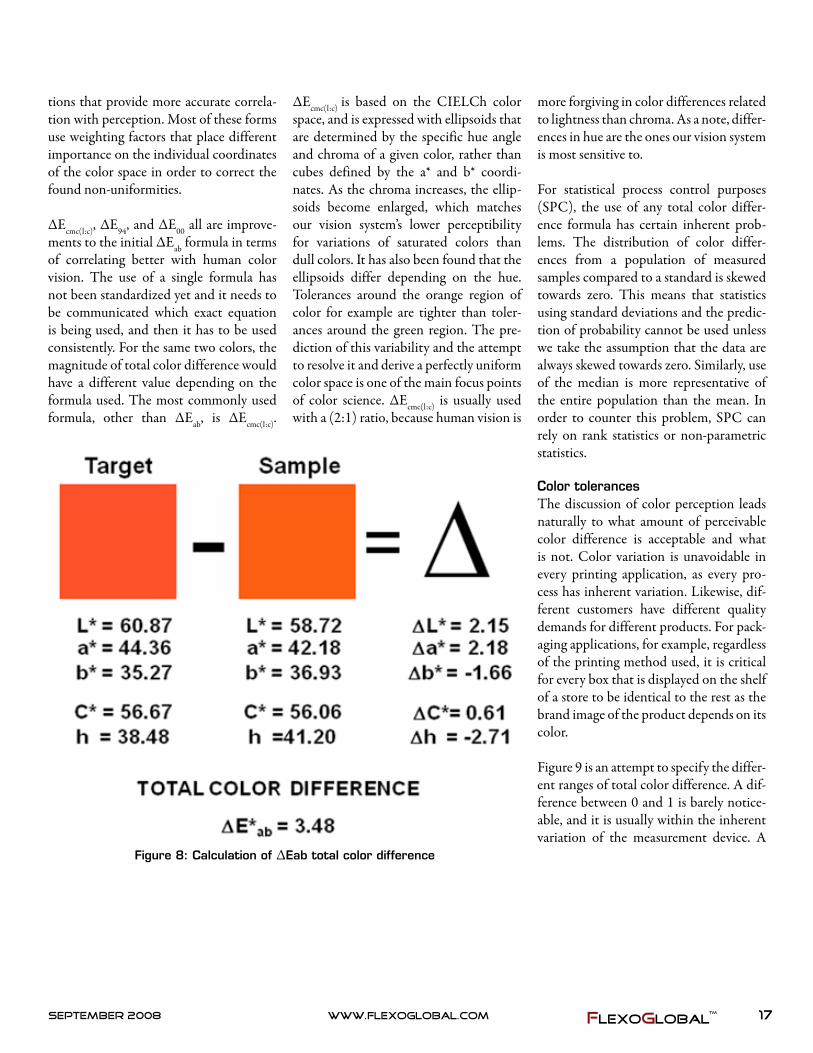
The color difference between two mea-sured colors can be expressed as their dif-ference (∆) in lightness (∆L* = L*1 – L*2), redness-greenness (∆a* = a*1 – a*2), and blueness-yellowness (∆b* = b*1 – b*2). These provide the difference in the light-ness and each of the chromatic dimen-
sions independently of each other. In order to get a measure of the magnitude of total color difference, the ∆Eab color difference formula is being used (ΔEab = [(L*1–L*2)^2+(a*1–a*2)^2+(b*1–b*2)^2]1/2). It is important to note that the ΔEab value can only be positive and it doesn’t take into account where the difference takes place. Two colors might have the same amount of total color difference from a standard, but the difference between them can be greater, the same, or less depending on the differences of the coordinates. In Figure 8, we see that the target is lighter, redder, and bluer than the sample, and the magnitude of the difference is 3.48 ΔEab.
The ΔEab total color difference formula, however, is not very accurate in predicting the color difference for samples that have differences in chroma. As the chroma value changes, the same amount of color difference correlates with perceptual dif-ferences that are not similar. In order to correct for this, CIE has developed a number of total color difference calcula-
17www.flexoglobal.comSeptember2008 FlexoGlobal
more forgiving in color differences related to lightness than chroma. As a note, differ-ences in hue are the ones our vision system is most sensitive to.
For statistical process control purposes (SPC), the use of any total color differ-ence formula has certain inherent prob-lems. The distribution of color differ-ences from a population of measured samples compared to a standard is skewed towards zero. This means that statistics using standard deviations and the predic-tion of probability cannot be used unless we take the assumption that the data are always skewed towards zero. Similarly, use of the median is more representative of the entire population than the mean. In order to counter this problem, SPC can rely on rank statistics or non-parametric statistics.
Color tolerancesThe discussion of color perception leads naturally to what amount of perceivable color difference is acceptable and what is not. Color variation is unavoidable in every printing application, as every pro-cess has inherent variation. Likewise, dif-ferent customers have different quality demands for different products. For pack-aging applications, for example, regardless of the printing method used, it is critical for every box that is displayed on the shelf of a store to be identical to the rest as the brand image of the product depends on its color.
Figure 9 is an attempt to specify the differ-ent ranges of total color difference. A dif-ference between 0 and 1 is barely notice-able, and it is usually within the inherent variation of the measurement device. A
Figure 8: Calculation of ΔEab total color difference
tions that provide more accurate correla-tion with perception. Most of these forms use weighting factors that place different importance on the individual coordinates of the color space in order to correct the found non-uniformities.
ΔEcmc(l:c), ΔE94, and ΔE00 all are improve-ments to the initial ΔEab formula in terms of correlating better with human color vision. The use of a single formula has not been standardized yet and it needs to be communicated which exact equation is being used, and then it has to be used consistently. For the same two colors, the magnitude of total color difference would have a different value depending on the formula used. The most commonly used formula, other than ΔEab, is ΔEcmc(l:c).
ΔEcmc(l:c) is based on the CIELCh color space, and is expressed with ellipsoids that are determined by the specific hue angle and chroma of a given color, rather than cubes defined by the a* and b* coordi-nates. As the chroma increases, the ellip-soids become enlarged, which matches our vision system’s lower perceptibility for variations of saturated colors than dull colors. It has also been found that the ellipsoids differ depending on the hue. Tolerances around the orange region of color for example are tighter than toler-ances around the green region. The pre-diction of this variability and the attempt to resolve it and derive a perfectly uniform color space is one of the main focus points of color science. ΔEcmc(l:c) is usually used with a (2:1) ratio, because human vision is

18 www.flexoglobal.com september2008FlexoGlobal
STandards
About the Author:Dimitri Pou-midis finished his Master of Science in Print Media from the Rochester Insti-tute of Technology, with a concentra-tion on Color Sci-ence. His thesis
dealt with the consistent reproduction of spot colors. During his studies, he worked in the Color Management System’s labs at the School of Print Media and did an internship with Graphics Microsystems. Upon graduation, Dimitri moved to California to work for Pacific Southwest Container as a Color Assurance Engineer (www.teampsc.com). Prior to his studies at Rochester, he completed a Bachelor’s of Science in Marketing in Greece, and worked as a printer, designer, and photog-rapher.
Please, submit any comments, questions, or topics you would like to discuss
on printcolor.blogspot.com under the post of the respective article.
Dimitri can also be contacted on [email protected].
tolerance between 1 and 3 is just notice-able and it is this range that commercial applications try to adhere to in produc-ing repeatable color. Tolerances above 3 ΔEab units are usually not acceptable, at least not within the same production run. It is a paradox, however, that the interna-tional standards for inks and process con-trol specify a ΔEab tolerance of 5.00 units for the primary colors, mainly because it would be difficult to standardize all the inks (and pigments) that are produced by different manufacturers. This does leave a rather big window for printers to con-form to the standards, with the drawback
Figure 9: A rough classification of a range of color tolerances
of allowing for color deviation between printers using inks from different suppli-ers.
ConclusionThe focus of this article was to provide a basic understanding of color theory and the elements that comprise it. The practi-cal application of color theory can be sum-marized on an understanding of CIELAB, color difference formulas, and color toler-ances. However, there is so much more to be said in these areas in relation with their actual application in the industry that it would be impossible to talk about both the science and its use in the same article. Having provided an outline of the science would allow us to talk and discuss the particular applications, without open-ing a parenthesis on what is the standard observer for example or what is status T density.
With that, I appreciate your patience in going through the theory, and I hope you have found some use for it. Now we can start discussing the applications of science to printing.

Balancing Between
Change and Tradition
Visit GravurExchangeTM Web Shop at http://gravurexchange.com/store/page2.html order your copy today !http://www.rit.edu/~gravure/
Balancing Between
Change and Tradition
RIT’s latest collaborative effort exploring the use of scientific method for color imaging & process control.
Given that change is essential, change itself does not always lead to better outcome. On the other hand, ‘more of the same’ or ‘tradition’ is not necessarily a bad thing. ‘Change’ or ‘more of the same’ also frequently surfaced when contemplating what to include in Test Targets 7.0. Test Targets 7.0 contains three broad sections: Articles, Gallery of Visual Interest (GVI), and Test Forms. In this edition of GVI showcases, we explored the synergy between graphic design and print with the idea of folded panels. The Folded panels not only provide extra ‘real estate’ for printed matter, but also support graphic design and communication in an interesting manner. Now
Available
Test Targets
7.0

20 www.flexoglobal.com september2008FlexoGlobal
Technology
OMET’s X-FLEX Press: New Benchmark in Press Performance!
OMET’s innovative new X-FLEX press was chosen as the leading
Technical Innovation of 2008 by the Flexographic Technical Association at the FTA Infoflex Forum. “We are proud and honored by this award,” said Angelo Bar-tesaghi, President OMET Srl.
The OMET X-FLEX press was first introduced at Labelexpo Europe 2007 and is considered to be a new benchmark in press performance!
Simplicity, Straight-ThruThe X-FLEX press represents new levels of automation and waste reduction. Its innovative design offers:
• Astableprintplatform• Superiorchangeovertimes• Userfriendliness
Using only 5.5 feet of web per print sta-tion, the X-FLEX press boasts the shorted web path of any flexo press on the market today!
One key feature of the X-FLEX press is its uniquely engineered print station that combines the impression cylinder and chill roll. This is the core source of the abbreviated web path. It is also one reason the press is able to average only 98 ft. of startup waste on an 8-color X-FLEX press!
In a UV configuration, the web path on the X-FLEX press is essentially a “straight-

21www.flexoglobal.comSeptember2008 FlexoGlobal
thru” design. The web travels over the combination impression-chill roll under the UV lamp, then straight to the next print station. This “Straight-thru” web path ensures print register stability and print quality at all speeds (from 0 to 660 fpm).
The Magic ButtonAnother factor in reducing waste on the X-FLEX press is the incorpora-tion of OMET’s exclusive “Vision” fully automatic register control system. This system automatically preregisters each print sleeve, and then fully registers every print station in both machine and lateral directions. This eliminates operator vari-able interference in registering each print job and virtually eliminates waste in job changeovers. OMET’s “Vision” system is so effective that some customers who are using it are already calling it “the magic button.”
Flexibility & ProductivityIn addition to its waste reduction capabil-ity, the X-FLEX press can handle substrates from ½-mil unsupported film to 10-mil carton board with equal ease. Using print sleeves, the X-FLEX press offers infinitely variable print repeats (metric or American sizes), and print changes can be accom-plished in a matter of seconds. Further enhancements include an innovative new ink pan design that requires only 8 ounces of ink to run a station (important for pan-tone, metallic, and expensive specialty inks). The ink pans are fully removable and anilox are gearless and incorporate an automatic cleaning function. All these fea-tures are part of OMET’s “Zero-Waste” concept that simplifies all press functions and offers exceptional productivity.
One of the key benefits of the X-FLEX press is that the operator is eliminated in the registration phase, which allows for standardization of time and waste costs for each job, independent of operator skills.
In addition to rapid changeovers, the
X-FLEX provides the same register stabil-ity at startup through acceleration/decel-eration and at production speeds up to 660 fpm.
X-FLEX vs. DigitalWith registration and control this pre-cise, the X-FLEX begs a comparison to digital presses. According to Steve Leibin, agent of Omet, “The initial investment, compared to digital, is very similar. If you were to buy an HP Indigo and a finishing machine, the cost is close to $1 million. A fully-equipped X-FLEX is about the same.”
Leibin professed that X-FLEX’s greatest strengths far outshine those of any digital
press; namely, ease of use, less waste, and cost-effective short runs. “For starters, your pressmen don’t have to learn digital printing, which some have said is a real problem. Printers have taken up to a year or more to become profitable with digital presses. But X-FLEX can run jobs as low as a few hundred feet and still be profit-able.”
On a short run, the waste generated by the X-FLEX is even less than on larger jobs. You wouldn’t even need to run the press that fast on a short run, which means your waste would be even less. A lot of printers struggle to be profitable at less than 10,000 ft. Older presses won’t even make money on an order of that size. And as jobs get

22 www.flexoglobal.com september2008FlexoGlobal
Technology
shorter and shorter, people are asking for only 5,000 ft. or sometimes just the pro-verbial 500 labels. The X-FLEX can run that length and still be profitable.
Omet’s new X-Flex press is now shipping to customers who ordered what they see as a new benchmark in narrow-web technol-ogy, according to Sales Director, Marco Calcagni. “Label printers have fallen for its innovative design that gives it unequalled production flexibility,” he said, “which allows them to realize an infinite range of products from film labels to complex multi-web applications.”
“We have received many compliments from companies who saw the X-Flex dem-onstrations in Brussels and from those who have come to our Demo Centre in Lecco. They seem most impressed by the innova-tive features on the X-Flex,” explained Mr. Calcagni.
Among the comments, one company believes “the X-Flex is unique in its design”, and another rates it as “the best solution in today’s label printing market.” Yet another company, which has carried out comparative print tests against rival machines, has no doubt that the “X-Flex is better under equal conditions,” while most rate its short web path and Vision-1 system as major breakthroughs in down-time and waste reductions.
One of the first X-Flex installations fol-lowing Labelexpo was at Label It SpA in Venice, whose CEO Giuseppe Picello commented, “The X-Flex is state-of-the-art innovation for today’s market. We like its top print quality, the way it can make fast format changes, which reduces expensive stoppages, and the way it cuts down substrate waste.” In times when
the competitiveness of a company is mea-sured more and more by these factors, it is important that the press operator concen-trates on printing in the knowledge that the machine will do the rest.
Omet’s innovative X-FLEX press is set-ting new standards for reduced makeready times and waste. The new X-FLEX press will be on display at LabelExpo Ameri-cas 2008 (Chicago, IL; September 9-11, 2008). Please stop by to see the most inno-vative press of 2008!
For more information, visit www.omet.com or contact Matik North America P:860-232-2323 email: [email protected]

23www.flexoglobal.comSeptember2008 FlexoGlobal
— theplacetobelisted—theplacetobelisted,whetheryou’reaflexographicprinter,printbuyer,supplier,tradeassociation,consultant,oreducator.
Simply visit:http://www.flexoglobal.com/flexoguideform.htm
orfill out the form below and mail it to:
FlexoGlobal, 7580 Salmon Creek Road, Williamson, NY 14589-9510
Company Information:
Company Name:
Main Address:
City, State, Zip, Country & Postal Code:
Phone: Fax:
E-mail: Web Site:
Sign-Off:Print your Name and Title:
Signature: Date:
FlexoGlobal’sResourceGuide
q anilox rollsq consultantsq consumer product companiesq educational institutionsq environmental equipment &
servicesq equipment manufacturersq graphic design services
q inks, pigments, coatingsq mounting tapesq packaging printer/convertersq plate manufacturersq prepress servicesq prepress softwareq press manufacturers q product/speciality printers
q quality inspection equipmentq substrate supplierq supplies & servicesq testing equipment manufacturerq transportationq workflow management
What Company Does: Our company offers the following products and/or services . . . (100 words maximum)
Company Category:
FlexoGlobalTM

24 www.flexoglobal.com september2008FlexoGlobal
Technology
Digital Flexo Delivers Competitive Edge to Autumn Graphics & Its Customers
A Success Story

25www.flexoglobal.comSeptember2008 FlexoGlobal
Autumn Graphics of London, Ontario, Canada, leverages the latest digital
equipment from Kodak to offer the high-est quality prepress and platemaking ser-vices to its customers. An independent, privately owned firm, founded in 1982, Autumn Graphics specializes in prepress production, plate production, and graph-ics management services for consumer products goods companies, converters, printers, and advertising agencies.
“We’ve been at this a long time. Every day we learn more about the flexo platemak-ing process and bring that growing knowl-edge to the services we offer our custom-ers,” says Ben Abray, president, Autumn Graphics. “With the variety of jobs that we handle, our operators know the most efficient approach to produce plates will yield high quality, repeatable results on press, while at the same time greatly reduce the need for on press adjustments and compensations.”
Abray notes that customers benefit because their platemaking costs are fixed, meaning they only pay for the plates and services they need and don’t have to carry an equipment investment that may or may not achieve the desired ROI as technol-ogy continues to change. Working with a partner that understands the technology and is able to serve as a dedicated resource leaves the customer free to address the other issues that play a role in the print job.
Whether the goal is to produce a label, tape or package where low cost is the most important feature, or to produce a top-quality package where color, appear-ance and compliance are critical, Autumn Graphics can utilize the most appropriate equipment to meet the customer need.
“Whereas some print service providers or converters view the plate production process as a formulaic step in production, we, as an outside supplier, must offer the very best for our customers,” adds Abray. “The offerings in the industry for imaging plates are always improving with each new generation, and we follow those develop-
ments very closely, investing in the right technology at the right time and imple-menting those solutions to provide the best plates for our customers.”
Because the flexo market is predominantly centered on narrow- and mid-web presses, Autumn Graphics does most of its work for those press formats. Abray points out that flexo printing is actually on the rise in the packaging market, and his com-pany’s expertise in imaging flexo plates is playing a role in its growth and success. With so much ongoing improvement in products and solutions in this market seg-ment, Abray is always looking for the next advantage.
Autumn Graphics has employed a variety of imaging devices, plates, and workflows to meet customer demands, evaluating each job individually, and finding the per-fect balance of quality, throughput and cost. Two of the primary devices in pro-duction over the past few years include the Kodak Thermoflex Narrow Plateset-ter and the Kodak Thermoflex Mid Pla-tesetter, both producing plates at the high quality needed for each job.
The ability to hold highlight dots as small as 10 microns enables the Flexcel NX digital flexographic plate to deliver gravure-class quality on press.
Ben Abray, President Autumn Graphics, LLC, says, “The Flexcel NX
System is a technology that helps our customers do a better job. That
makes them listen to what we have to offer.”
26 www.flexoglobal.com september2008FlexoGlobal
Technology
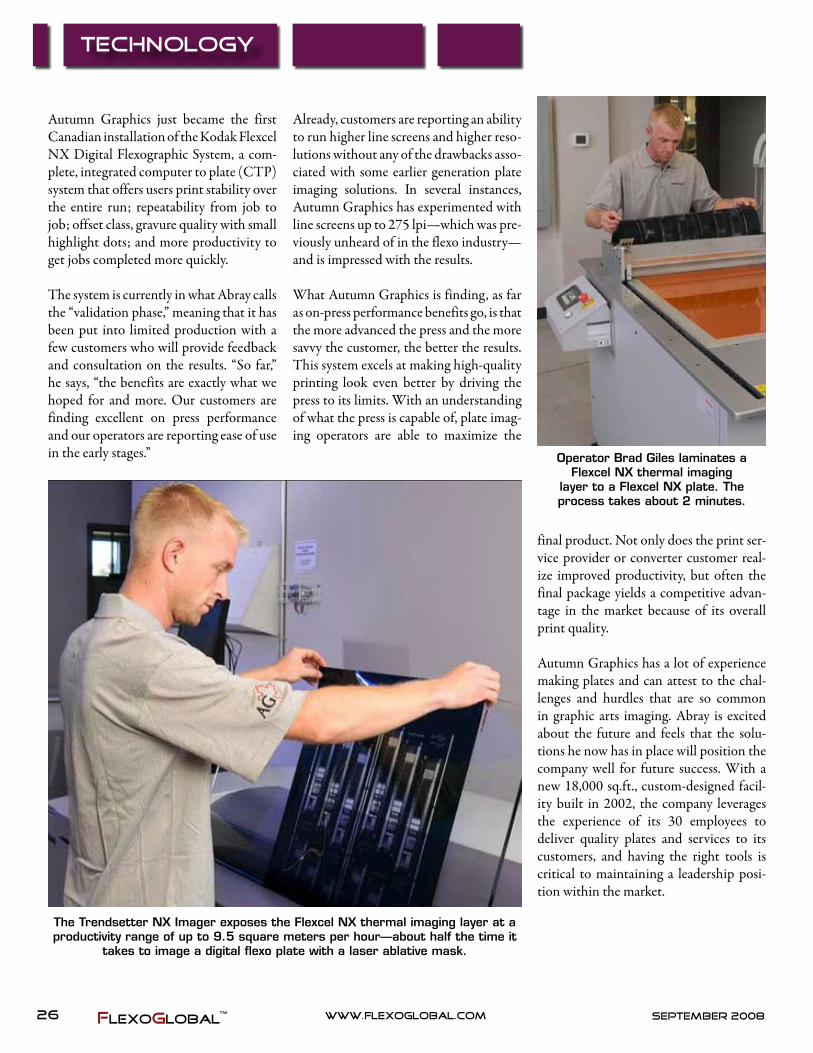
Autumn Graphics just became the first Canadian installation of the Kodak Flexcel NX Digital Flexographic System, a com-plete, integrated computer to plate (CTP) system that offers users print stability over the entire run; repeatability from job to job; offset class, gravure quality with small highlight dots; and more productivity to get jobs completed more quickly.
The system is currently in what Abray calls the “validation phase,” meaning that it has been put into limited production with a few customers who will provide feedback and consultation on the results. “So far,” he says, “the benefits are exactly what we hoped for and more. Our customers are finding excellent on press performance and our operators are reporting ease of use in the early stages.”
final product. Not only does the print ser-vice provider or converter customer real-ize improved productivity, but often the final package yields a competitive advan-tage in the market because of its overall print quality.
Autumn Graphics has a lot of experience making plates and can attest to the chal-lenges and hurdles that are so common in graphic arts imaging. Abray is excited about the future and feels that the solu-tions he now has in place will position the company well for future success. With a new 18,000 sq.ft., custom-designed facil-ity built in 2002, the company leverages the experience of its 30 employees to deliver quality plates and services to its customers, and having the right tools is critical to maintaining a leadership posi-tion within the market.
The Trendsetter NX Imager exposes the Flexcel NX thermal imaging layer at a productivity range of up to 9.5 square meters per hour—about half the time it
takes to image a digital flexo plate with a laser ablative mask.
Operator Brad Giles laminates aFlexcel NX thermal imaging
layer to a Flexcel NX plate. The process takes about 2 minutes.
Already, customers are reporting an ability to run higher line screens and higher reso-lutions without any of the drawbacks asso-ciated with some earlier generation plate imaging solutions. In several instances, Autumn Graphics has experimented with line screens up to 275 lpi—which was pre-viously unheard of in the flexo industry—and is impressed with the results.
What Autumn Graphics is finding, as far as on-press performance benefits go, is that the more advanced the press and the more savvy the customer, the better the results. This system excels at making high-quality printing look even better by driving the press to its limits. With an understanding of what the press is capable of, plate imag-ing operators are able to maximize the

27www.flexoglobal.comSeptember2008 FlexoGlobal
To learn more, call 704.588.3371or Toll Free 866.588.8686
No one has more environmentally-friendly, Aluminum-safe ways to clean your anilox rolls than HarperScientific.
Call one of our cleaning specialists today—866.588.8686
Protect Your Anilox Investment.
Our Anilox Roll Cleaners are not only backed by a 100% performanceguarantee, they are both safe for your rolls, and safe for the world.Whether you need water based or solvent based products; in powders orliquids; by the gallon, box, tub or drum, we’ve got the proven solution.
HARPERSCIENTIFIC DIVISION
HARPERIMAGE.COMAmericas • Europe • Asia
©2008
To learn more, call 704.588.3371or Toll Free 800.438.3111
This Is What Total Commitment to Flexo Looks Like.
XLT Anilox Rolls are 100% performance guaranteed for quality and consistencyand supported by the most knowledgeable sales technicians in the industry.
ANILOX & COATING ROLLS DIVISION
A team of Flexo experts with knowledge of every aspect of the business. Provensolutions to make your plant run more efficiently from our Consulting Division.
GRAPHICSOLUTIONS DIVISION
Protect your Anilox investment with environmental-friendly, roll-safe cleaners, rollcovers, racks and accessories. Handproofers that save ink, substrate & press time.
HARPERSCIENTIFIC DIVISION
Free seminars at our advanced facility or coming to a city near you.
ROAD SHOWS & WALKINGSEMINARS
Scholarships, grants and funds invested in the future of the Flexographic Industry.
THE HARPER EDUCATION PROJECT
HARPERIMAGE.COMAmericas • Europe • Asia
©2008

28 www.flexoglobal.com september2008FlexoGlobal
Education
Introduction
The minimum dot is a topic of inter-est and mystery for many in flexog-
raphy. It can bring the production floor to a screeching halt while people begin trou-bleshooting or cleaning plates if the char-acteristic hard edge in the print can’t be recognized. A flexographic printing plate that doesn’t hold a minimum dot is easy to identify once you know what to look for. It is a phenomenon that has always been an issue, but warrants explanation for those new to the flexographic process.
MechanicsThe minimum dot phenomenon origi-nates from the fact that light energy must pass through a negative or mask to harden the photopolymer enough to form a dot. The opening in the mask must be large enough to allow enough light to react with the plate polymer for a given expo-sure time. If the opening is too small, the
Minimum Dot for Photopolymer Flexo Defined By Kern Cox & Rory Marsoun, Clemson University
flexo dot will not fully form, which people tend to refer to as “drop off.”
ImportanceWhy is minimum dot such a big concern for flexographic printing? Two hand-in-hand reasons: tone break and dot gain. To
explain further, the opening in the nega-tive might, for example, need a minimum opening size of 20 microns to allow enough light to pass through and sufficiently react with the photopolymer. Let’s say this size opening corresponds to a 3 percent dot in the electronic file. Therefore, the mini-
Spots on the plate where dots are completely missing.

29www.flexoglobal.comSeptember2008 FlexoGlobal
What is print? It’s how we communicate. How enterprises are enabled and individuals influenced. Here, there, and everywhere. Kodak provides answers for a dynamic, diverse marketplace. See for yourself at Drupa. Kodak solutions are here. Print is powerful.
Visit kodak.com/go/packagingSee the power of Kodak innovation at Drupa, Hall 5.©Kodak, 2008. Kodak is a trademark.
here
here aquí
aquíici
hier
hier
qui
here
47888_KGCG_DrupaAd_CM.indd 1 3/6/08 3:32:22 PM

30 www.flexoglobal.com september2008FlexoGlobal
Education
mum dot would be a 3 percent file dot. Any image element smaller than 3 percent in the electronic image (like highlights in a person’s face or features in a sky) will dis-appear altogether because the plate won’t hold it. Therefore, a sudden tone break
is noticeable in the printed image that is objectionable to the viewer.
ExampleDot gain now comes into effect and com-pounds the issue of tone break. Here’s
how it works using a simple one color on white substrate as an example. The substrate is the brightest highlight (0 percent) that can be achieved. The next highlight tone after the substrate is the minimum dot that can be held on the printing plate. This minimum plate dot might correspond to a 3 percent file dot. This minimum dot then grows as result of dot gain to something like a 13 percent printed dot. The eye detects a harsh tran-sition from 0 percent to 13 percent and the viewer interprets this as a defect in the image. To compound this, ink drying can occur at this minimum dot edge and cause a build up of ink that appears as an even darker edge in the print.
Forms of Minimum DotThis brings up a very real issue that can get overlooked in handling a minimum dot. There are actually two forms of mini-mum dot a plate provider must be aware of. First is what we have been discussing all along—the physical minimum dot that can be held on the printing plate. Second is the production minimum dot. This dot is the on the plate that will dynami-cally hold up during a production press run. Most commonly, this can relate to the drying speed of the ink. If the press crew prints with a fast-drying ink, the 3 percent file dot could realistically dry up,
The black dots in the sky drop off leaving a noticeable hard edge.
Notice the significant jump in density from white substrate to smallest black dot.
Distinct drop of the cyan dot in the red ball leaves a noticeable edge.

31www.flexoglobal.comSeptember2008 FlexoGlobal
meaning it may not be the best choice as a minimum dot. A press characterization will not always recognize this because the press run is too short. That is why running control targets on all jobs is important. They give long-run, “live” print data.
Digital BumpWith the growing popularity of digital flexo plates, the minimum dot is still a concern that must be addressed. The term used in digital plates is “bump.” Digi-tal dots shrink (aka sharpen) during UV exposure. Because of this, the mask open-ing is “bumped” open wider so a mini-mum physical plate dot is held. Usually RIP output is manipulated so a 1 percent file dot is bumped up to, as an example, a 7
percent corresponding dot opening in the mask. That 7 percent mask opening will sharpen back down to a very small (some-times less than 1 percent) dot on the plate. This takes care of the physical plate; how-ever, the electronic file dot must still be handled to ensure there is no dot less than 1 percent in the image. This is why the separator or plate maker must always take care to set a minimum electronic dot in the artwork even when using digital plates. It is also important to mention that an ICC profile does not recognize a minimum dot and this must still be manually set after
conversion from RGB to CMYK.
The minimum dot is a topic that has mul-tiple discussion elements we can go into; however, the fundamental mechanics have been related in this article.
Clemson University’s Department of Graphic Communications hosts a variety of training programs for the printing and packaging industry through its Print/Con Center. For more information please visit www.clemson.edu/printcon or call 864-646-5749.
Vignettes or Gradients require special care since they inherently fade to 0 percent or substrate and show the
hard edge.
One of many ways to set a minimum dot is with curves in Photoshop. Notice an input value of 0 percent is forced to an output value of 1 percent.

32 www.flexoglobal.com september2008FlexoGlobal
Technology
Viscosity, your last dollar.... By Joseph K. Steingraeber, Steingraeber LLC Industrial Viscosity
During a recent PLGA conference, a leading color expert described vis-
cosity as “your last dollar in the printing process.” This professor tells his students, “It is your last chance to get it right.” Thank you, Dr. Chung, for this clear per-spective of viscosity relative to achieving color results.
Do liquid media, ink, or coatings get this priority in printing processes? Too often, viscosity is the most questioned and least-controlled process in printing. In many cases, ink costs have increased from 3 percent to nearly 6 percent of the printed product, and solvents continue to rise and are near $7.00 a gallon. With these cost increases, now may be a good time to reconsider if the best methods for ink handling and options for ink control are being utilized in your process.
Is your operation reactively or proactively managing inks?Whether the print process is flexo, gra-vure, or offset, our quality demands require expensive ancillary equipment and components designed to make the print process consistent and repeatable. Significantly, investment in premium doctor blades, anilox rolls, spectropho-tometers, vision systems, and a multitude of other ancillaries is the norm. Finally, there is a struggle for QC and production to afford a few new, precisely machined cups to replace bent-up Zahn cups parked in a bucket of slurry awaiting their next deployment.
Plant-wide, ink management is crucial to achieving not only quality initiatives, but

33www.flexoglobal.comSeptember2008 FlexoGlobal
Accountability for manually checking viscosity every 15 minutes and correcting with smaller incremental quantities of sol-vent is a good step to better viscosity con-trol. This is a simple solution and begins with test cups, a stopwatch, and a chart to track changes.
Test Cup and Stopwatch
Start with the Right Test Cups for Manual Viscosity MeasurementViscosity measurement with a test cup remains the basic procedure to manage liquid ink media on the printing press. The corresponding flow rates (in seconds) are used for scales in most automatic con-trols and devices. In order to accurately
Examples of Test Cups worldwide:DIN 53211 for lab measurements
OC-DIN (*) for production usage FORD (ASTM) (*) Zahn Cups (ASTM) (*) ISO
2431 (*) … and many more.
(*) Various nozzle sizes are available to function with the working range for
each application.
also cost initiatives. Your knowledge of viscosity control principles and systems is your last dollar when it comes to main-taining consistent color. Viscosity changes color, and thicker viscosity increases ink usage and cause undesirable effects in the resultant print quality. Modern high-speed presses take a greater toll on inks, and vis-cosity will exponentially increase with every cycle through the press. For gravure, flexo, and offset coating towers, viscosity is an ongoing challenge to manage.
Today, there are many solutions available in manual viscosity cups relative to size, design, and speed. There are also many automatic controls including rotational, falling ball, and others. Inherently, all vis-cometers, regardless of their design, will work, but choosing the correct device that will best function in your production environment is the key.
Understanding the foundational basics of viscosity measurement—where it started, who was the first to measure viscosity, and current solutions available—is a good place to start. Let’s begin with the world’s first-known viscometer.
In the beginningThe father of viscosity was Sir Isaac Newton. Yes, the man who was hit in the head with an apple was instrumental in the development of viscosity measure-ment.For lab and process, Newton chose to measure liquid media using two plates with liquid media between theses plates, as shown in example 1. The speed and shear rate were obtained from his test apparatus.
The only problem with the plates was that measurement ended with the length of the base plate. Later, this challenge was overcome with a rotating system using a torque meter, as shown in example 2.
The Wrong Side of the Viscosity CurveWhen the ink room sends a five-gallon kit of ink reading 28-32 seconds on a Zahn 2 cup to a CI press the color repeatability is often lost in the first cut when a gallon of solvent overcorrects the ink. A few min-utes later, the press is back online with over-adjusted ink at 17-19 seconds, where it needed to be 22 seconds. The press runs 15-30 minutes and the lead operator looks at his vision system, pulls a sample, and informs the helper to check that kit again. The helper finds the viscosity now rose to 26 seconds and makes another massive correction causing a temporary washout. If it is white ink, there can be a loss in opac-ity; if it is a red ink, color repeatability just fell off the chart. If this scenario sounds familiar, more routine viscosity checks with smaller, incremental corrections can help stabilize the process.

34 www.flexoglobal.com september2008FlexoGlobal
Technology
regulate viscosity, measurements must be done with clean cups on a consistent basis along with incremental corrections to maintain viscosity. Worldwide, there are more than 50 different types of test cups available, which have a wide range of different nozzles and volumes and pro-vide unique values when tested in a single liquid. When considering flow time, the type of cup and nozzle must be evaluated to best meet your process.
It is important to recognize that not all types of cups deliver precise measurement results. While different types of cups are more or less recommended, it is the operator using estimations based on his/her own habits of measurement relative to the start and end of flow time that can change the results. The individual opera-tion of stopwatch and the behavior of the viscosity cup is a challenge that can often complicate what is often perceived to be a simple procedure.
A common mistake when using cups is the viscosity range. Test cups are recom-mended for flow times of more than 20 sec. But in practice, there are many opera-tions that make measurements in the range of 10-15 sec. The relative inaccu-racy is then much too high. In such a case, it is urgently recommended to change to a
smaller nozzle size. Getting an expert rec-ommendation regarding the proper test cup to use in your process is a good first step to improve viscosity control.
The most accurate viscosity cup remains subject to the operator. With different operators handling these cups, the manual nature of this measuring process can inter-fere with producing the desired color results. When manual measurement with viscosity cups is not consistent with your process, there are a multitude of automatic systems available to provide precise viscos-ity control.
General Ideas: Automatic Sensor & Control TypesWhen manual checking is not practical or not sufficient to maintain quality, auto-matic controls can be a good solution. For those printing gravure, flexo or offset with flexo coating towers, automatic con-trols can help you with color repeatability. In the coating applications, these devices help to improve gloss and maintain closer tolerances with slide angle specifications.
Viscosity Sensor TypesAutomatic viscosity controls are most reli-able when they operate in “real time” con-stant measurement. Simple set-point and actual display of the specific cup values with no conversion chart are most conve-nient for operators. Keep it simple, choose a system that requires a single utility like 110V electricity that can be installed without a service technician. In order to make full use of viscosity controls, they need to have user-friendly actual and set-point control. Cleanup should require no more effort than what is needed to wash up a Zahn cup. Following these principles will grow operator confidence and assure full usage of the ink controls. Try before you buy—viscosity controls are one of the few ancillary controls that can be tested in your operation with minimal efforts.

35www.flexoglobal.comSeptember2008 FlexoGlobal
Bypass Tank Installation
Inline Rotational Viscometer Alternatives
Dip sensors are simple to install
Inline Sensors
Rotation Dip Sensors Rotation sensors for use in the main tank or in a bypass system are very popular due to their simple handling, installation, and reliability. The sensors are dipped verti-cally into the liquid assuring convenient availability for checking. When changing ink, sensors conveniently store in a quiver filled with solvent for cleaning and stor-age.
Dip Sensors, even like this (not recommended), can work safely and
accurately!
Inline SensorsThese inline rotational sensors utilize a patented magnetic clutch system without bearings or a spindle in the ink chamber. Inline sensors are best used in environ-ments where ink is contamination free. This type of device is often used in print-
ing, paint, and a multitude of other liquid media environments that require closed inline viscosity control. These inline type sensors install into a bypass line or directly into the main line.
36 www.flexoglobal.com september2008FlexoGlobal
Technology
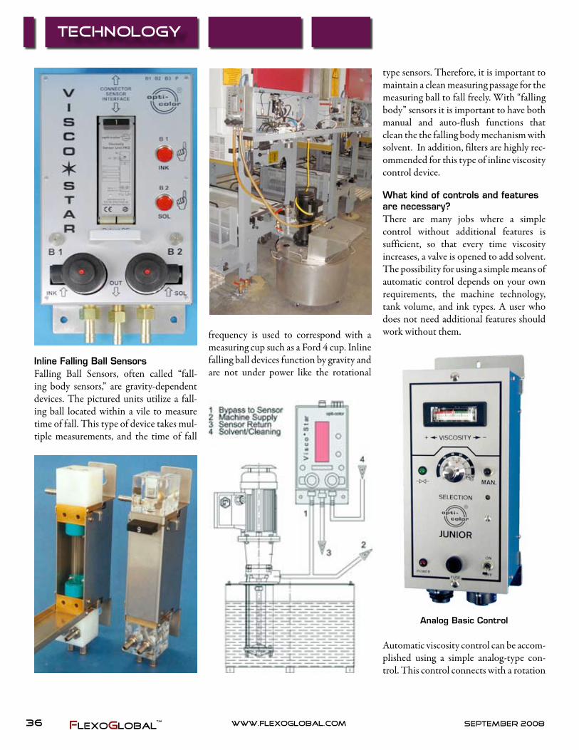
Inline Falling Ball SensorsFalling Ball Sensors, often called “fall-ing body sensors,” are gravity-dependent devices. The pictured units utilize a fall-ing ball located within a vile to measure time of fall. This type of device takes mul-tiple measurements, and the time of fall
frequency is used to correspond with a measuring cup such as a Ford 4 cup. Inline falling ball devices function by gravity and are not under power like the rotational
type sensors. Therefore, it is important to maintain a clean measuring passage for the measuring ball to fall freely. With “falling body” sensors it is important to have both manual and auto-flush functions that clean the the falling body mechanism with solvent. In addition, filters are highly rec-ommended for this type of inline viscosity control device.
What kind of controls and features are necessary?There are many jobs where a simple control without additional features is sufficient, so that every time viscosity increases, a valve is opened to add solvent. The possibility for using a simple means of automatic control depends on your own requirements, the machine technology, tank volume, and ink types. A user who does not need additional features should work without them.
Analog Basic Control
Automatic viscosity control can be accom-plished using a simple analog-type con-trol. This control connects with a rotation

37www.flexoglobal.comSeptember2008 FlexoGlobal
sensor and valve to create a fully automatic system. With this type of control unit, the operator can bring the ink to color, turn on the switch, and adjust a potentionme-ter to set the level to control the viscos-ity. Each notch on the readout indicates about 1 second on the viscosity cup. The green side is thin viscosity and the red side is thick viscosity and will automatically add solvent when it thickens over your set point. When the unit is set on the edge of the green, it will maintain the ink color or coating for the duration of the run. Basic analog viscosity controls have been in operation for decades and remain popular today due to their simplicity.
Junior VC Control
Fully digital automatic controls such as the Junior VC connect with rotation or falling ball sensors. The unit was designed as a straightforward control to be used in print and liquid media applications where viscosity and valve timing control is paramount to the process. The valve timing has precise controls for delay, on, and off times. This functionality allows the ink to be checked without overreact-ing to coagulated bodies of thick ink that
can pass through the measuring device. Once the unit determines that viscosity has increased, a set amount of solvent is added. After the new solvent is added, the valve timing has a set-off time to allow the ink to properly mix with the newly added solvent. Timed Incremental solvent cor-rections are made possible with this type of control This unit has fully adjustable features and is popular in flexo and gra-vure printing.
When using large volume tanks or inks with special behaviors in regard to common viscosity curves, then additional features are necessary and intensive tech-nical evaluation of your process is a must. For demanding applications, units such as the Multi VC controls with interface to oc-4000 software is a solution. These units provide multiple control channels that will simultaneously measure three different values such as viscosity, tem-perature, and pH-values. Multiple lines of solvents can also be controlled using this type of device. The universal control pictured below can be adapted to nearly every viscosity control application in exis-tence today.
MultiVC Universal Control
Scale functionAutomatic viscosity control systems are most comfortable to work with when the
display contains the same values as the cup. This helps to make a smooth transi-tion from manual to automatic control and gives operators confidence in the devices.
Internal Functions of Control UnitsViscosity control devices and systems have internal differences in values as revolutions or time of falls are counted. The values are displayed on a scale. Many devices are equipped with only one fixed scale, which refers to one type of cup and one specified range of viscosity. When there are new cups and inks that differ from the stan-dard or when a change is made to another type of cup, often there is no chance to adapt the control device’s display to the new situation. Control units such as the Multi VC contain up to 50 or more dif-ferent scales, and it is possible to generate new scales for adaption to the cup values with the Multi VC. Scale adaptability is essential in cases where either rotation or a falling body system are used. Changes in scaling—i.e., from ZAHN cup to another type like FORD or from one size cup (ZAHN 2) to another (ZAHN #3)—are immediately available within the Multi VC control unit program. The possibil-ity to change to other scales and adapt to various measuring application requires a universal kind of unit. The purpose of having a Multi VS type unit is to address a multitude of different viscosities and have flexibility to add additional capability when needed.
Data transfer, printer function and interfacesFor system integration and data transfer, the corresponding interfaces are necessary. The Multi VC type control is designed to operate with open interfaces to connect within the system’s integrated printer pro-tocols. There are times when it can help to have an interval printout to document viscosity during the print job. The opera-
38 www.flexoglobal.com september2008FlexoGlobal
Technology
tor is then able to show documentation of viscosity when it becomes necessary. For data transfer to other systems and cen-tral computers—also for remote control of device, (i.e., with the opti-color 4000 software—there is a serial interface avail-able. With central control software, the entire MultiVC system is centralized on a singe touch-screen control the can store jobs and track performance throughout your runs.
Interval function for dosing valve When having high volumes or bypass installation (at rotation or falling body sensors), there is an adjustable delay in control. It takes some time from adding solvent up to the point of mixing it into the complete system, and it is only after this time delay that it can be determined whether additional solvent is required. For this purpose, a control of valve open-ing time is required that makes it possible to set the minimum or maximum volume of added solvent. There is the delay time
before the control starts. Then follows an opening time, which delivers a specified solvent volume. After this comes a clos-ing time. In this time, the added solvent can be mixed into the system. Otherwise, the valve would open for too long caus-ing low ink viscosity. Incremental solvent correction is the best practice when man-aging the ink kits. Valve timing controls allow for grams and ounce stabilization compared to the drastic shock effects that result from pint and quart corrections.
TemperatureTemperature influences various factors in the printing process. The correct start temperature is optimal for the starting vis-cosity of the above-mentioned controls, but normally not for the viscosity control itself. A heated liquid has lower viscosity values compared to the same liquid that is in a cool condition. Temperature is critical for high viscosity UV, aqueous coatings, and certain water-based ink applications.
Temperature fluctuations also increase or decrease foaming problems in the coating circulation. Water-based coatings often result in foam caused by the circulation, stirrers, and micro air bubbles brought in by the anilox roller. When we find separate macro-foam (bigger bubbles and foam swimming on the surface of liquids in the tanks) and micro-foam (smaller air “particles” within the volume of the liquid), this causes problems resulting in a poor printing result. When a printing unit transfers coatings with micro-foam, and especially when gloss or gold effects are required, the printing and coating results are dull, and the gold is not brilliant. The reason is that the micro-foam opened up holes, and the final print surface ends up looking like moon craters. The shine or gloss can be lost without the use of some form of temperature control and proper mixing.
Coating suppliers have developed some highly concentrated water dispersions with viscosities up to 120 seconds (DIN 4 mm), and development continues. The highest levels of gloss are normally only achieved with a UV-coating. In order to work with high-viscosity water-based coating dispersions, the starting tempera-ture of the water-based media is normally even higher compared to UV-media. Here
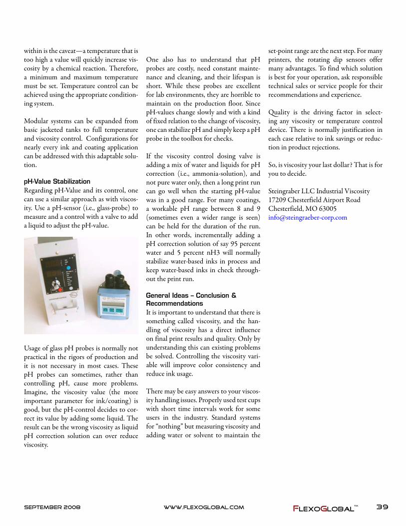
39www.flexoglobal.comSeptember 2008 FlexoGlobal
within is the caveat—a temperature that is too high a value will quickly increase vis-cosity by a chemical reaction. Therefore, a minimum and maximum temperature must be set. Temperature control can be achieved using the appropriate condition-ing system.
Modular systems can be expanded from basic jacketed tanks to full temperature and viscosity control. Configurations for nearly every ink and coating application can be addressed with this adaptable solu-tion.
pH-Value StabilizationRegarding pH-Value and its control, one can use a similar approach as with viscos-ity. Use a pH-sensor (i.e., glass-probe) to measure and a control with a valve to add a liquid to adjust the pH-value.
Usage of glass pH probes is normally not practical in the rigors of production and it is not necessary in most cases. These pH probes can sometimes, rather than controlling pH, cause more problems. Imagine, the viscosity value (the more important parameter for ink/coating) is good, but the pH-control decides to cor-rect its value by adding some liquid. The result can be the wrong viscosity as liquid pH correction solution can over reduce viscosity.
One also has to understand that pH probes are costly, need constant mainte-nance and cleaning, and their lifespan is short. While these probes are excellent for lab environments, they are horrible to maintain on the production floor. Since pH-values change slowly and with a kind of fixed relation to the change of viscosity, one can stabilize pH and simply keep a pH probe in the toolbox for checks.
If the viscosity control dosing valve is adding a mix of water and liquids for pH correction (i.e., ammonia-solution), and not pure water only, then a long print run can go well when the starting pH-value was in a good range. For many coatings, a workable pH range between 8 and 9 (sometimes even a wider range is seen) can be held for the duration of the run. In other words, incrementally adding a pH correction solution of say 95 percent water and 5 percent nH3 will normally stabilize water-based inks in process and keep water-based inks in check through-out the print run.
General Ideas – Conclusion & RecommendationsIt is important to understand that there is something called viscosity, and the han-dling of viscosity has a direct influence on final print results and quality. Only by understanding this can existing problems be solved. Controlling the viscosity vari-able will improve color consistency and reduce ink usage.
There may be easy answers to your viscos-ity handling issues. Properly used test cups with short time intervals work for some users in the industry. Standard systems for “nothing” but measuring viscosity and adding water or solvent to maintain the
set-point range are the next step. For many printers, the rotating dip sensors offer many advantages. To find which solution is best for your operation, ask responsible technical sales or service people for their recommendations and experience.
Quality is the driving factor in select-ing any viscosity or temperature control device. There is normally justification in each case relative to ink savings or reduc-tion in product rejections.
So, is viscosity your last dollar? That is for you to decide.
Steingraber LLC Industrial Viscosity17209 Chesterfield Airport RoadChesterfield, MO [email protected]

40 www.flexoglobal.com september2008FlexoGlobal
FlexoHighlight
Innovia Films’ biodegradable, com-postable, and flexible packaging mate-
rial, NatureFlex™, is an integral part of a packaging first for an Australian ginger-bread biscuit producer.
Based in the Blue Mountains in New South Wales, Gingerbread Folk is the brainchild of former architect turned biscuit-maker, Karen Sharman, and her husband, Dominic Mason. Two years ago, they decided to make their gingerbread business as sustainable as possible from the sourcing of the ingredients through to the packaging.
The NatureFlex™ pack used for the Gin-gerbread Folk range of biscuits is the first of its kind in Australia to be certified com-postable and carries the “seedling” logo to confirm this. To be certified, the mate-rial must undergo a stringent test regime, carried out by independent accredited laboratories only, in order to confirm that their inclusion will have no negative effect
on soil or compost quality.
NatureFlex™ was an obvious solution for the packaging as the film begins life as a natural product—wood and breaks down in a home compost bin (or industrial compost environment) within a matter of weeks—yet also offers advantages for packing and converting such as inherent deadfold and anti-static properties, high gloss and transparency, resistance to grease and oil, good barrier to gases and aromas, and a wide heat-seal range.
Outlining why Gingerbread Folk opted for NatureFlex™, Karen said, “We were looking for environmentally sound pack-aging to compliment our all natural gin-gerbread and ethical business philoso-phy. We tried many films, but loved the look and feel of NatureFlex™ and found the material’s properties the most suit-able for our purposes. The key factor was home compostability because we wanted to show the Australian public that it was
okay to put these bags in their own home compost bins.”
All NatureFlex™ films are cellulose based, derived from renewable wood pulp and are certified to meet both the European EN13432 and American ASTM D6400 standards for compostable packaging. The wood pulp is sourced from managed plantations from referenced suppliers operating Good Forestry principals (FSC or equivalent). NatureFlex™ films typi-cally have a renewable biobased content of some 95 percent by weight of material.
Packsys, an Australian based company, is the converter of the NatureFlex™ film in this application and achieved the certi-fied compostable status for the Ginger-bread Folk pack. Clive Jacobs of Packsys said, “Being one of the first Australasian companies to achieve the DinCertco cer-tification shows our commitment to com-postable packaging. As a plastic packag-
NatureFlex™ Part of Packaging First Down Under

41www.flexoglobal.comSeptember2008 FlexoGlobal
ing converter, we have an obligation and responsibility to promote and advise our customers of the compostable and sus-tainable substrates available. NatureFlex™ out of all the available materials suits itself extremely well to automated produc-tion like flow-wrapping or bag making. The material requires very little machine adjustment and can run in harmony with conventional materials through the same machine. NatureFlex™ is also a very easy material to print and convert. Speeds are
not reduced so conversion costs remain on par with other substrates.”
For more information on Gingerbread Folk visit www.gingerbreadfolk.com. For more information on Packsys visit www.packsys.com.au.
Innovia Films Ltd, is a major producer of Biaxially Oriented Polypropylene (BOPP) and cellulose (Cellophane™) films with production sites in the UK (based at
Wigton in Cumbria), USA, Belgium and Australia. It holds a leading global posi-tion in the markets for labels and security films, coated packaging, overwrap and bio-degradable and compostable films under the brand-name NatureFlex™, employing some 1,400 people worldwide (900 staff are based at Wigton in Cumbria). Nature-Flex™ is a registered trademark of Innovia Films Group. For more information on Innovia Films Group, visit www.innovia-films.com.
ANSI/CGATS TR 011-2002An ANSI Technical Report Prepared by Committee for Graphic Arts Technologies Standards (CGATS)
Graphic Technology — Package Development Workflow — Design Concept Through Approved Production File
Now Available through FlexoGlobalat http://gravurexchange.com/store/page2.html
FlexoGlobalTM

42 www.flexoglobal.com september2008FlexoGlobal
Technology
All Eyes on Printed Electronics
Source: Industry statistics
Printed and potentially printed elec-tronics were first seen as a way of
sharply reducing the cost of everything from lighting to personal electronics. That remains an objective. However, it is also proving to be a way of providing electronic and electrical devices that were previously impossible to manufacture. This includes
transparent displays, transistors, lighting, loudspeakers, photovoltaics, sensors, and batteries. There are devices working in the terahertz band and wide-area devices such as sensors, ac electroluminescent, and other displays and photovoltaics. And they are increasingly deposited on top of each other. This is leading to components
and products that can re-invigorate the markets below:
Little wonder, then, that analysts see printed electronics rising exponentially to around $300 billion in twenty years’ time, with the demand for conductive inks alone reaching several billion dol-lars yearly in little more than five years from now. Little wonder that over 1,500 organizations across the world are now doing major work in this area, about half of them being academic. That is about twice the level of interest and investment of only three years ago, and it goes beyond the well-publicized organic electronics—indeed, half the materials being developed and used for printed electronics are inor-ganic. The number of patents in all aspects is sharply increasing as giant corporations down to startups announce a raft of excit-ing new inventions.
The conventional silicon chip is hitting the buffers. Major problems include the cost of the research and development sup-

43www.flexoglobal.comSeptember2008 FlexoGlobal
porting improved production rising expo-nentially and the cost of silicon factories rising exponentially. This is what Profes-sor Neil Gershenfeld of Massachusetts Institute of Technology calls the “Inverse Moore’s law.” Making small quantities of chips is already expensive, and design and production changes are slow and expen-sive. The next step down in transistor size (to reduce cost and provide cleverer circuits) results in short chip life. In addi-tion, making chips ever smaller means you cannot subsume large components such as displays, batteries, antennas, micro-phones, etc. They cannot be put on top of the tiny chip, so they all have to be con-nected alongside, thus creating something big and unreliable. Printed electronics can get over almost all of these problems and can also take us into a new world.
Here we have the magic of the new meta-materials, with their negative refractive index and other surreal properties prom-ising previously impossible devices, from the cloak of invisibility to unusually small RFID labels. For example, some metama-terials are flexographically printed to give the necessary microscopic three-dimen-sional patterns over a wide area, such as split ring resonators on microwires.
We now have the reduction in melting point of metals by a factor of ten achieved by printing them in particles of only a few nanometers across. They can then be annealed on something as delicate as acetate film. What are the new products soon to be launched in biodegradable paper electronics and in electrophoretics where the display uses no electricity until it is changed? The leaders are being eagerly followed as they push the boundaries for-ward, from tightly rollable electronics and power to edible electronics.
Development of exciting new materials is central to this revolution, there being
rapid advances in performance thanks to the new nanosilicon semiconductors in printed transistors and photovoltaics, new organic materials printed in the form of batteries, inorganic compounds both as semiconductors and as photovoltaic films, some of which work off heat as well as light. Will printed copper finally replace the printed silver used in everything from touchpads and testers on Duracell batter-ies to smart skin patches for drug deliv-ery? Where will the new concept of ori-gami electronics take us beyond the fold-able two-meter disco light shown below? Packaging that is refolded after use into a useful electronic or electrical product is one hot idea for brand enhancement while enhancing environmental credentials.
The end result is the replacement of bill-boards, posters, and books with repro-grammable printed electronic film. Smart packaging will inform, prompt, warn, entertain, and record when you took your pills thanks to printed logic, moving color displays, light, sound, and electronically
triggered aromas. Medical test instruments will become everyday disposables kept in your pocket. The move of healthcare from hospital to home and on the move is also facilitated with printed diagnostic patches and other affordable inventions.
The effects can be multiplied when elec-tronics and electrics are printed onto smart substrates. These include self-heal-ing plastic recently developed in France and “Polymer based Ultrasonic Paper PUP” from ITRI Taiwan. Physiotherapy and large area motion detectors are envis-aged that will use the latter. Polymers have recently been demonstrated that change electric properties when stretched and electroactive polymers change shape under electrical bias.
The exciting new frontiers of science and product development will be aired at the conference “Printed Electronics Asia” in Tokyo Japan on October 8-9. There will be visits to local centres of excellence in printed electronics, optional Masterclasses

44 www.flexoglobal.com september2008FlexoGlobal
Technology
and an exhibition. This truly global event will be double the size of last year’s meet-ing, reflecting the burgeoning interest in the subject. Once again, it will be univer-sal in coverage, giving equal emphasis to both inorganic and organic materials and devices. The best speakers will fly in from all over the world.
For example, there will be presentations from Kodak, Toppan Forms, Sony and the University of Cambridge in the UK where light emitting polymers were first
discovered. We shall hear from e-ink of the USA, Samsung of Korea, Thin Film Electronics of Sweden, with its printed organic mega memory, and NXT of the UK with its transparent film loudspeak-ers. Waseda University of Japan will give the latest on its new translucent organic batteries deposited on polymer film and the latest research at the Institute of Materials Research and Engineering and display leader Bridgestone in Japan will be presented. A further stream of new products will be revealed by the Univer-
sity of Tokyo and Toppan Forms. Hitachi of Japan, H.C. Starck of Germany and other experts will discuss their remark-able advances in materials and production machinery will also be covered. Kovio will come from California to present on how their ink jet printed nanosilicon transistor circuits can meet silicon chip specifica-tions at a fraction of the cost.
For further information, please contact Chris Clare at [email protected]
FlexoGlobal is a “Hot“ Publication!
Just look for the typed out hyperlinks or blue text in the body of articles and click! .And don’t forget that all advertisements are “hot” as well. Just slide your mouse over the page and off you go!

45www.flexoglobal.comSeptember2008 FlexoGlobal
Fox Valley Technical College (FVTC) & Association of Independent
Corrugated Converters (AICC) Seminars
Fundamentals of Improved Flexographic Printing & Rotary Die Cutting Seminars
Monday, Tuesday & Wednesday
June 23-25, 2008
August 18-20, 2008
Who should attend: Press operators, press supervisors, sales representatives, and other plant personnel.
What you’ll learn: This 3-day graphics and die cutting program combines hands-on press work in printing and die cutting 2 and 3 color jobs using a WORKHORSE 3-color flexo rotary die cutter with interactive classroom analysis and discussion. You will acquire new skills to improve operations back at the plant. $1,250 AICC members, $1,450 nonmembers
Digital Production for Containers and Displays
Wednesday & Thursday
October 8-9, 2008
Who should attend: Customer service, pre-production, production, supervisors and line management
What you’ll learn: This NEW intensive workshop teaches digital production and processes. The program covers digital workflows, coordination of the various production components; equipment utilized, and includes live on-site demonstrations. The agenda covers corrugated manufacturing in a digital world, workflow and component coordination, equipment and processes, demonstration of digital production flow, putting the digital production puzzle together, and making it happen back when you return to your workplace. $995 AICC members, $1095 nonmembers
Sell to Your Manufacturing Capabilities
Thursday & Friday
May 8-9, 2008
Who should attend: Sales people and designers
What you’ll learn: This NEW program teaches trends in graphic communications; markets of opportunities for converters; case study of one company’s approach to selling digital; business development selling strategies; and creating a plan using specific strategies and tactics that meet appropriate client needs. $995 AICC members, $1095 nonmembers
Seminars are held at FVTC, Appleton WI
Register with the AICC at (877) 836-2422 or (703) 836-2422
http://www.aiccbox.org/
For additional information visit
http://www.fvtcedu/flexo or call FVTC at 920-735-4755

46 www.flexoglobal.com september2008FlexoGlobal
2008 Flexographic PrintingTraining Opportunities
FUNDAMENTALS OF WIDE WEB PRESS OPERATION
JULY 14 – 16 | NOV 3-5 The goal of this 3-day seminar is to give the participant equal instruction between theory and
hands-on activities in the area of flexo platemounting and wide web press operation.
Topics covered: Flexographic printing theory, press components and operation, ink handling and
management, print setting adjustments, register, and tension control, mounting, anilox rolls,
doctor blades and chambered blade assembly and maintenance, press set-up, run, and clean-up
and documentation. $795/person/ includes all materials, morning breaks, noon lunches & extras.
FF UNDAMENTALS OF UNDAMENTALS OF NNARROW ARROW WW EB EB PP RESS RESS OO PERATION PERATION
JUNE 9 -12, | SEPT 29-OCT. 2 This 3 day seminar provides the basic information necessary for the production of quality
flexographic printing. Instruction will consist of lectures, demonstrations and operation of
machinery in the various subject areas.
Topics covered: Flexographic art and copy, line, tone, and process printing, prepress functions,
plates, press components and operation, anilox rolls, substrates, inks, solvents, inline converting
and troubleshooting. $795/person/ includes all materials, morning breaks, noon lunches & extras.
FVTCFVTC IS YOUR TRAINING SO IS YOUR TRAINING SO UU RCE FOR ALL FLEXO RCE FOR ALL FLEXO
APPLICATIONSAPPLICATIONS
VV ISIT US ISIT US ATAT WWWWWW .. FVTCFVTC .. EDUEDU // FLEXOFLEXO
OR CALL OR CALL
920920 --735735 --47554755 FOR FOR RR EGISTEGISTRATION RATION II NFORMATIONNFORMATION
FF OX OX VVALLEY ALLEY TT ECHNICAL ECHNICAL CCOLLEGE OLLEGE && FF LEXOGRAPHIC LEXOGRAPHIC TT ECHNICAL ECHNICAL AA SSOCIATIONSSOCIATION
AACHIECHIE VING VING CCONSISTENCY IN ONSISTENCY IN PP ROCESS ROCESS PP RINTING RINTING 20082008
Choose your training date
• June 16-19
• October 6-9
Register with the FTA
(631) 737-6026
www.flexography.org
This seminar deals with the concepts and tools involved in
the production of high quality, repeatable process printing.
Lectures, demonstrations, a field trip, and printing a four-
color process job on an 8-color, central impression gearless
press are included.
Topics covered: Process color theory, image assembly and
prepress proofing, densitometry and Spectrophotometry,
plate making, press operation, characterization and
documentation, process ink handling, anilox usage and
maintenance.