flexible & powerful - efes otomasyon - endüstriyel … · 2013-01-05 · 284 800-334-3040...
TRANSCRIPT
284
www.emersonct.com
800-334-3040
Fincor
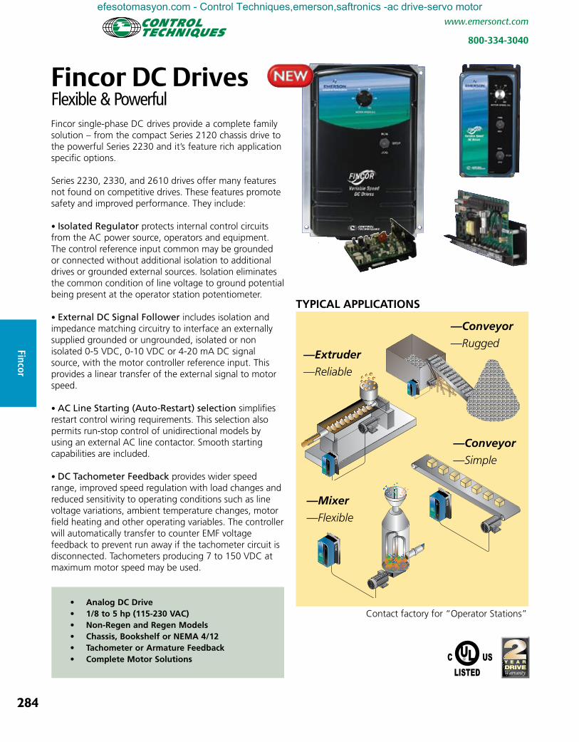
Fincor DC DrivesFlexible & Powerful Fincor single-phase DC drives provide a complete family solution – from the compact Series 2120 chassis drive to the powerful Series 2230 and it’s feature rich application specific options.
Series 2230, 2330, and 2610 drives offer many features not found on competitive drives. These features promote safety and improved performance. They include:
• Isolated Regulator protects internal control circuits from the AC power source, operators and equipment. The control reference input common may be grounded or connected without additional isolation to additional drives or grounded external sources. Isolation eliminates the common condition of line voltage to ground potential being present at the operator station potentiometer.
• External DC Signal Follower includes isolation and impedance matching circuitry to interface an externally supplied grounded or ungrounded, isolated or non isolated 0-5 VDC, 0-10 VDC or 4-20 mA DC signal source, with the motor controller reference input. This provides a linear transfer of the external signal to motor speed.
• AC Line Starting (Auto-Restart) selection simplifies restart control wiring requirements. This selection also permits run-stop control of unidirectional models by using an external AC line contactor. Smooth starting capabilities are included.
• DC Tachometer Feedback provides wider speed range, improved speed regulation with load changes and reduced sensitivity to operating conditions such as line voltage variations, ambient temperature changes, motor field heating and other operating variables. The controller will automatically transfer to counter EMF voltage feedback to prevent run away if the tachometer circuit is disconnected. Tachometers producing 7 to 150 VDC at maximum motor speed may be used.
• Analog DC Drive • 1/8 to 5 hp (115-230 VAC)• Non-Regen and Regen Models• Chassis, Bookshelf or NEMA 4/12• Tachometer or Armature Feedback• Complete Motor Solutions
RUN
JOGSTOP
2230
MOTOR SPEED (%)
RUN
JOGSTOP
2610
MOTOR SPEED (%)
RUN
JOGSTOP
2330
MOTOR SPEED (%)
—Conveyor
—Rugged—Extruder
—Reliable
—Mixer
—Flexible
—Conveyor
—Simple
TYPICAL APPLICATIONS
RUN
JOGSTOP
2610
MOTOR SPEED (%)
Contact factory for “Operator Stations”
efesotomasyon.com - Control Techniques,emerson,saftronics -ac drive-servo motor

285
www.emersonct.com
800-334-3040
Finc
or
Order String
Operator Controls: 0 = No Controls 1 = Speed Pot, Run-Stop-Jog 2 = Speed Pot, Run-Stop-Jog, & Fwd-Rev Switch Reversing 3 = Speed Pot, Run-Stop-Jog, & Fwd-Rev Contactor Reversing 7 = Speed Pot, Run-Stop-Jog, & Auto-Manual
Enclosure: No Letter = Chassis, P = Enclosed (top cover)
Armature Contactor: No Letter = None, A = Armature Contactor Reversing with DB, B = Armature Contactor with DB
Current Step
Drive Series Revision Level
1 = 2120 Ultra Compact, 2 = 2230 Regen Feature Rich, 3 = 2330 Non-Regen Full Featured, 6 = 2610 Non-Regen Feature Rich
2 = Single Phase Input Drive Model
2 x x x x x x
CHOOSE NON-REGEN OR REGENERATIVENon-regenerative drives are used when friction or a dynamic brake stopping is adequate. A contactor may be used to achieve reversing operation. Non-regen drives are less expensive than Regen drives when reversing is not required.
Regenerative drives include static reversing and are used when you need four quadrant control or Forward & Reverse operation from a bidirectional control signal (+/- 10 VDC). It will stop the load smoothly and faster than a dynamic brake for fast stop or emergency stop requirements and it will regenerate power to the supply if the load is overhauling (wanting to go faster than the motor set speed).
CHOOSE DRIVE SERIESNow choose the drive series from either Non-Regen or Regen product pages. The chart below compares features and horsepower ratings, with the simplest and least expensive drive at the top and highest horsepower range and flexibility towards the bottom.
Reg
ener
ativ
e
Series
2120
2330
2610
2230
Horsepower
Non
-Reg
ener
ativ
e
Basic DriveNon-isolated Speed Input
Full FeaturedIsolated Speed & Torque Input
Feature RichIsolated Speed & Torque Input with Monitoring Output
Feature RichIsolated Speed & Torque Input with Monitoring Output
Fincor Single Phase DC Selection Chart
Contact your local Distributor, Control Techniques’ Representative or see www.emersonct.com for upgrade and cross reference information regarding Focus, Puma or Lynx series DC drives.
efesotomasyon.com - Control Techniques,emerson,saftronics -ac drive-servo motor

286
www.emersonct.com
800-334-3040
Fincor
Non-regenerative drives are typically used on applications which primarily motor in one direction and stopping is achieved through friction or infrequent use of a dynamic braking resistor. These drives may provide speed or torque control from a potentiometer or unidirectional (0-10 VDC or 4-20 mA) control signal. Reversing requires a switch or
contact closure to initiate the change. Upon the reversing signal, the drive will allow the motor to coast to a stop (or perform a control stop under a decel ramp with control stop option) or utilize a dynamic braking resistor to pull it to a stop before switching the motor leads with a contactor and starting the motor in the opposite direction.
Fincor Series 2100 drives feature compact size and lowest pricing. Chassis units are dimensionally interchangeable with many competitive units and are ideal for the OEM or panel builder who builds a custom system by integrating the drive into an enclosure with special logic or auxiliary control devices. NEMA 1 enclosed units are complete self-contained packages ready for wall or machine mounting.
• 1/8 to 3 hp (115 -230V) • Budget Priced • Speed Control • Current Limit • UL Listed
Fincor Series 2120
Fincor Non-Regen Drives
RATINGS: 1/8 TO 3 hp (115-230 VAC)Series 2100 Non-Regenerative DC Drives
ModelMotor
HP 2
Input Output RUN-STOP
AC Volts Amps DC Volts Amps
Order Code Arm Field Arm Field
Chassis1
1/8-1/2 115 8.7 90 50/100 5.4 1.0 21211/8-1/2 115 8.7 90 50/100 5.4 1.0
21221/2-1.0 230 8.8 180 100/200 5.5 1.01/8-1.0 115 15 90 50/100 10.5 1.0
2122H1/2-2.0 230 15.8 180 100/200 11.6 1.01/8-1.0 115 15 90 50/100 10.5 1.0
21231/2-3.0 230 24 180 100/200 16 1.0
NEMA 1 Enclosed1/8-1/2 115 8.7 90 50/100 5.4 1.0 2121P11/2-1.0 230 8.7 180 100/200 5.4 1.0 2122P1
(2) Units may be easily recalibrated using trimpots for any standard rating within the hp range.
Option Description Order Code
Knob and Dial Plate Kit — This option provides a knob and a dial face graduated 0-100% for use with the potentiometer provided with Series 2120 chassis drives.
106409401
External Signal Follower/Isolation — For use with isolated or non isolated 4-20 mA DC, 0-10 VDC signals. Includes a scaling potentiom-eter for offset adjustment. Dimensions 1.5” (38) X 3.38” (86) X .75” (19).
2067109
2123
2122H
2121 & 2122
Enclosed
efesotomasyon.com - Control Techniques,emerson,saftronics -ac drive-servo motor

287
www.emersonct.com
800-334-3040
Finc
or
Fincor Series 2120 DIMENSIONS
1.87”(48 mm)
Weight (Chassis)1 lb. .45 kg
7”(178 mm)
4.25”(108 mm)
2123 Chassis
1.64”(42 mm)
Weight (Chassis).5 lb. .23 kg
4.25”(108 mm)
3.55”(90 mm)
2121 & 2122 SPECIFICATIONS: Operating Conditions Horsepower 1/8 thru 3 hp , Trim Pot Selectable
Line Voltage 115-230 VAC ±10%, Bi Voltage Input* Rated Frequency 50/60 Hz ±2%
Enclosure Chassis, NEMA 1
Ambient Temperature 0 – 40°C (32°F - 104°F) (Enclosed)
0 – 55°C (32°F - 131°F) (Chassis)
Altitude 1000 m (3,300 ft)
Relative Humidity 95% Non condensing
Overload Capacity 150% for 1 minute
Standard Features Regulator Function Speed Regulated
Power Conversion 2 SCR plus Freewheeling Diode
Field Supply Full Wave
Protection MOV Voltage Transient Suppression High Interrupting Capacity Line Fuse
Speed Regulation Armature or DC Tach Feedback*
Control Control Logic Power Common for Maintained Switch
Speed Potentiometer 5K Ohms, ½ Watt
Input Reference 0 – 10 VDC
Speed Regulation 2% with Armature Feedback (95% Load Change) 1% with Tachometer Feedback*
Adjustments Maximum Speed 60% – 100% of Motor Base Speed
Minimum Speed 0% – 40% of Motor Base Speed
Current Limit 0 – 150% of Full Load
IR Compensation 0 – 100% Boost
Acceleration/Deceleration 0-4 Seconds*
Efficiency Controller (only) 98%
With Motor (typical) 85%
Approvals & Listings UL and cUL
* The 2121, 2121P1 and 2122P1 are single input voltage (115, 115 & 230 VAC respectively), do not offer DC Tach Feedback, and have fixed acceleration and deceleration rates.
Weight (Chassis).5 lb. .23 kg
4.25”(108 mm)
3.55”(90 mm)
2”(50.8 mm)
Enclosed 3.00 ”
(76.2 mm)
9.00”(228.6 mm)
3.12”(79.25 mm)
Weight (Enclosed)1 lb. .45 kg
2330
RUN
STOP
Variable SpeedDC Drives
FUSE TYPEMDA1010A, 250V2122H Chassis
Chassis
efesotomasyon.com - Control Techniques,emerson,saftronics -ac drive-servo motor
288
www.emersonct.com
800-334-3040
Fincor
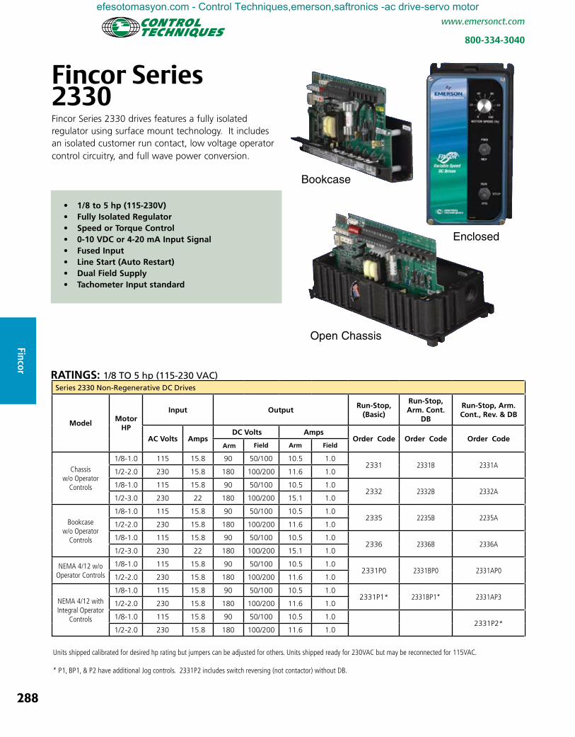
Fincor Series 2330Fincor Series 2330 drives features a fully isolated regulator using surface mount technology. It includes an isolated customer run contact, low voltage operator control circuitry, and full wave power conversion.
Enclosed
Open Chassis
Bookcase
• 1/8 to 5 hp (115-230V)• Fully Isolated Regulator• Speed or Torque Control• 0-10 VDC or 4-20 mA Input Signal• Fused Input• Line Start (Auto Restart)• Dual Field Supply• Tachometer Input standard
RATINGS: 1/8 TO 5 hp (115-230 VAC)Series 2330 Non-Regenerative DC Drives
ModelMotor
HP
Input OutputRun-Stop,
(Basic)
Run-Stop, Arm. Cont.
DB
Run-Stop, Arm. Cont., Rev. & DB
AC Volts Amps DC Volts Amps
Order Code Order Code Order Code Arm Field Arm Field
Chassisw/o Operator
Controls
1/8-1.0 115 15.8 90 50/100 10.5 1.02331 2331B 2331A
1/2-2.0 230 15.8 180 100/200 11.6 1.0
1/8-1.0 115 15.8 90 50/100 10.5 1.02332 2332B 2332A
1/2-3.0 230 22 180 100/200 15.1 1.0
Bookcase w/o Operator
Controls
1/8-1.0 115 15.8 90 50/100 10.5 1.02335 2235B 2235A
1/2-2.0 230 15.8 180 100/200 11.6 1.0
1/8-1.0 115 15.8 90 50/100 10.5 1.02336 2336B 2336A
1/2-3.0 230 22 180 100/200 15.1 1.0
NEMA 4/12 w/o Operator Controls
1/8-1.0 115 15.8 90 50/100 10.5 1.02331P0 2331BP0 2331AP0
1/2-2.0 230 15.8 180 100/200 11.6 1.0
NEMA 4/12 with Integral Operator
Controls
1/8-1.0 115 15.8 90 50/100 10.5 1.02331P1* 2331BP1* 2331AP3
1/2-2.0 230 15.8 180 100/200 11.6 1.0
1/8-1.0 115 15.8 90 50/100 10.5 1.02331P2*
1/2-2.0 230 15.8 180 100/200 11.6 1.0
Units shipped calibrated for desired hp rating but jumpers can be adjusted for others. Units shipped ready for 230VAC but may be reconnected for 115VAC.
* P1, BP1, & P2 have additional Jog controls. 2331P2 includes switch reversing (not contactor) without DB.
efesotomasyon.com - Control Techniques,emerson,saftronics -ac drive-servo motor
289
www.emersonct.com
800-334-3040
Finc
or
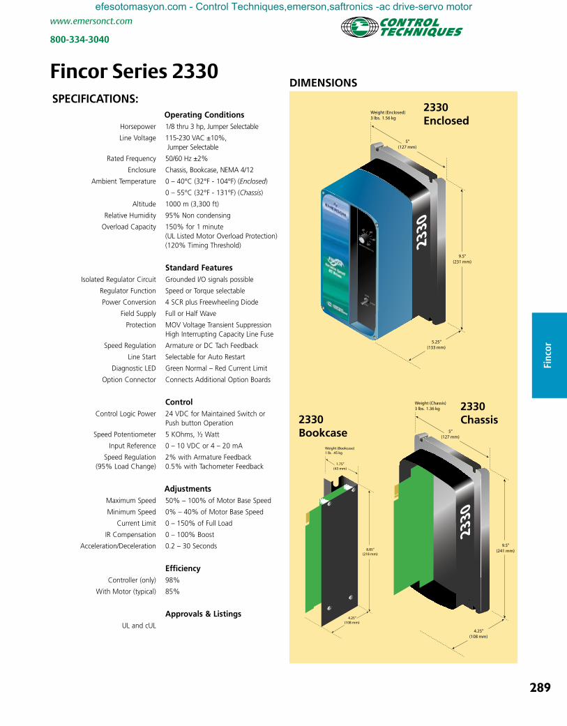
Fincor Series 2330DIMENSIONS
5”(127 mm)
9.5”(231 mm)
5.25”(133 mm)
Weight (Enclosed)3 lbs. 1.56 kg
RUN
JOGSTOP
2330
MOTOR SPEED (%)
5”(127 mm)
9.5”(241 mm)
4.25”(108 mm)
Weight (Chassis)3 lbs. 1.36 kg
2330
1.75”(43 mm)
8.85”(218 mm)
4.25”(108 mm)
Weight (Bookcase)1 lb. .45 kg
2330 Enclosed
2330 Chassis2330
Bookcase
SPECIFICATIONS: Operating Conditions Horsepower 1/8 thru 3 hp, Jumper Selectable
Line Voltage 115-230 VAC ±10%, Jumper Selectable
Rated Frequency 50/60 Hz ±2%
Enclosure Chassis, Bookcase, NEMA 4/12
Ambient Temperature 0 – 40°C (32°F - 104°F) (Enclosed)
0 – 55°C (32°F - 131°F) (Chassis)
Altitude 1000 m (3,300 ft)
Relative Humidity 95% Non condensing
Overload Capacity 150% for 1 minute (UL Listed Motor Overload Protection) (120% Timing Threshold)
Standard Features Isolated Regulator Circuit Grounded I/O signals possible Regulator Function Speed or Torque selectable
Power Conversion 4 SCR plus Freewheeling Diode
Field Supply Full or Half Wave
Protection MOV Voltage Transient Suppression High Interrupting Capacity Line Fuse
Speed Regulation Armature or DC Tach Feedback
Line Start Selectable for Auto Restart
Diagnostic LED Green Normal – Red Current Limit
Option Connector Connects Additional Option Boards
Control Control Logic Power 24 VDC for Maintained Switch or Push button Operation
Speed Potentiometer 5 KOhms, ½ Watt
Input Reference 0 – 10 VDC or 4 – 20 mA
Speed Regulation 2% with Armature Feedback (95% Load Change) 0.5% with Tachometer Feedback
Adjustments Maximum Speed 50% – 100% of Motor Base Speed
Minimum Speed 0% – 40% of Motor Base Speed
Current Limit 0 – 150% of Full Load
IR Compensation 0 – 100% Boost
Acceleration/Deceleration 0.2 – 30 Seconds
Efficiency Controller (only) 98%
With Motor (typical) 85%
Approvals & Listings UL and cUL
efesotomasyon.com - Control Techniques,emerson,saftronics -ac drive-servo motor
290
www.emersonct.com
800-334-3040
Fincor
Minimum Speed
+10V RefExt Current Ref Input
Circuit Common
Tachometer Fdbk InputRun Enable Input (+24 VDC)
+24 VDCRun Relay N.O. ContactsRun Relay N.O. Contacts
Current Loop Follower Input
Speed Ref Input
Motor Armature
Speed Ref Pot
Torque Ref Pot
4-20 mA
HalfWaveField
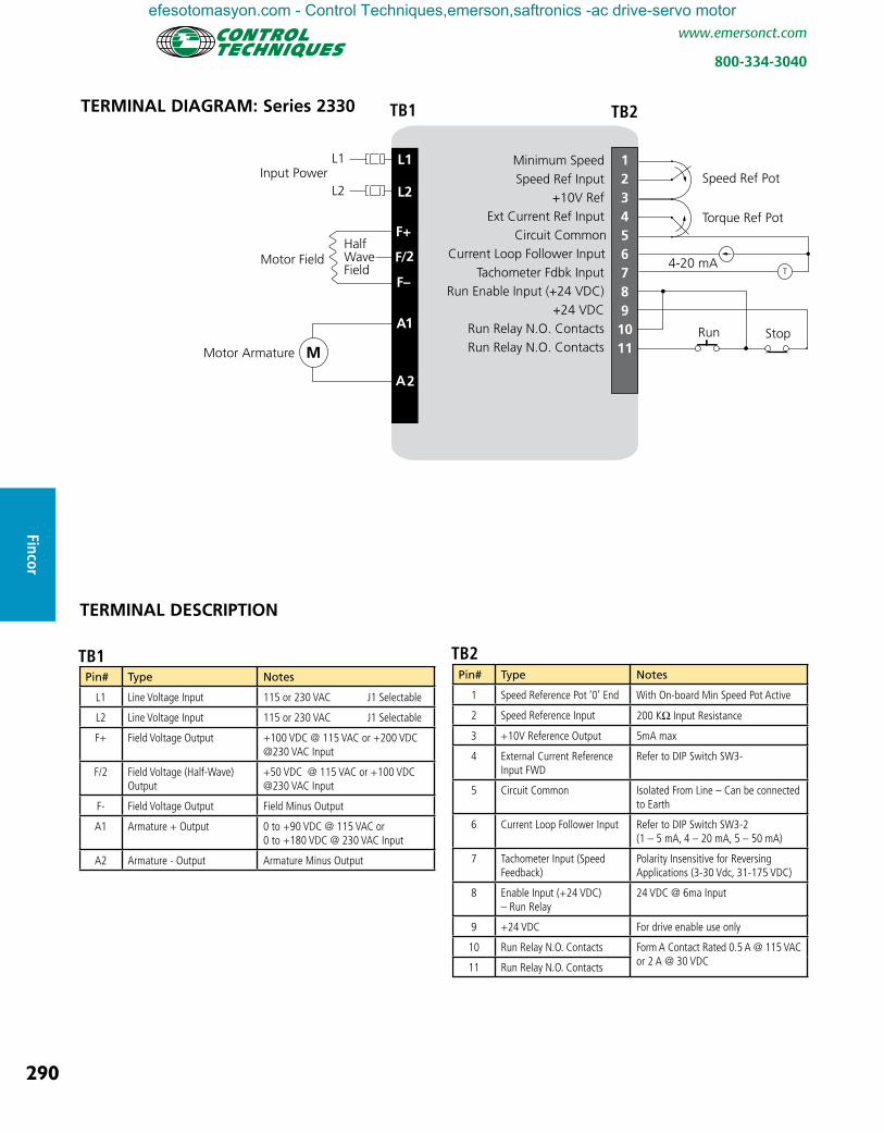
TERMINAL DIAGRAM: Series 2330
TERMINAL DESCRIPTION
Pin# Type Notes
L1 Line Voltage Input 115 or 230 VAC J1 Selectable
L2 Line Voltage Input 115 or 230 VAC J1 Selectable
F+ Field Voltage Output +100 VDC @ 115 VAC or +200 VDC @230 VAC Input
F/2 Field Voltage (Half-Wave) Output
+50 VDC @ 115 VAC or +100 VDC @230 VAC Input
F- Field Voltage Output Field Minus Output
A1 Armature + Output 0 to +90 VDC @ 115 VAC or 0 to +180 VDC @ 230 VAC Input
A2 Armature - Output Armature Minus Output
TB1Pin# Type Notes
1 Speed Reference Pot ‘0’ End With On-board Min Speed Pot Active
2 Speed Reference Input 200 KΩ Input Resistance
3 +10V Reference Output 5mA max
4 External Current Reference Input FWD
Refer to DIP Switch SW3-
5 Circuit Common Isolated From Line – Can be connected to Earth
6 Current Loop Follower Input Refer to DIP Switch SW3-2 (1 – 5 mA, 4 – 20 mA, 5 – 50 mA)
7 Tachometer Input (Speed Feedback)
Polarity Insensitive for Reversing Applications (3-30 Vdc, 31-175 VDC)
8 Enable Input (+24 VDC) – Run Relay
24 VDC @ 6ma Input
9 +24 VDC For drive enable use only
10 Run Relay N.O. Contacts Form A Contact Rated 0.5 A @ 115 VAC or 2 A @ 30 VDC11 Run Relay N.O. Contacts
TB2
TB1 TB2
efesotomasyon.com - Control Techniques,emerson,saftronics -ac drive-servo motor

291
www.emersonct.com
800-334-3040
Finc
or
2610 Enclosed Fincor Series 2610 drives feature a fully isolated regulator using surface mount technology. It includes additional inputs and outputs with advanced control capabilities.
Fincor Series 2610
• 1/8 to 5 hp (115 – 230 VAC) • Fully Isolated Regulator • Speed or Torque Control • 0 – 10 VDC or 4 – 20 mA input signal • PID / Speed Trim Control • Monitoring Output (0 – 10 VDC or 4 – 20 mA) • Line Start /Auto Restart Enable/Disable • Dual Field Supply • DC-Tachometer Input
Open ChassisRATINGS: 1/8 TO 5 hp (115-230 VAC)
Series 2610 Non-Regenerative DC Drives
Model MotorHP
Input OutputRun-Stop,
(Basic)
Run-Stop, Arm. Cont.
DB
Run-Stop, Arm. Cont., Rev. & DB
AC Volts Amps DC Volts Amps Order Code Order Code Order Code
Arm Field Arm Field
Chassis
1/8-1.0 115 15.8 90 50/100 10.5 1.02611 2611B 2611A
1/2-2.0 230 15.8 180 100/200 11.6 1.01/8-1.0 115 15.8 90 50/100 10.5 1.0
2612 2612B 2612A1/2-3.0 230 22 180 100/200 15.1 1.51/8-1.0 115 15.8 90 50/100 10.5 1.0
2613 2613B 2613A1/2 -5.0 230 32 180 100/200 25 2.0
Bookcase w/o Operator
Controls
1/8-1.0 115 15.8 90 50/100 10.5 1.02615 2615B 2615A
1/2-2.0 230 15.8 180 100/200 11.6 1.0
NEMA 4/12 w/o Integral Operator
Controls
1/8-1.0 115 15.8 90 50/100 10.5 1.02611P0 2611BP0 2611AP0
1/2-2.0 230 15.8 180 100/200 11.6 1.01/8-1.0 115 15.8 90 50/100 10.5 1.0
2613P0 2613BP0 2613AP01/2-5.0 230 32 180 100/200 25 2.0
NEMA 4/12 with Integral Operator
Controls
1/8-1.0 115 15.8 90 50/100 10.5 1.02611P1* 2611BP1* 2611AP3*
1/2-2.0 230 15.8 180 100/200 10.5 1.01/8-1.0 115 15.8 90 50/100 10.5 1.0
2613P1* 2613BP1 2613AP3*1/2-5.0 230 32 180 100/200 25 2.01/8-1.0 115 15.8 90 50/100 10.5 1.0
2611P2*1/2-2.0 230 15.8 180 100/200 11.6 1.01/8-1.0 115 15.8 90 50/100 10.5 1.0
2611P7 2611BP7Manual / Auto
Switch.
1/2-2.0 230 22 180 100/200 15.1 1.51/8-1.0 115 15.8 90 50/100 10.5 1.0
2613P7 2613BP71/2-5.0 230 32 180 100/200 25 2.0
Units shipped calibrated for desired hp rating but jumpers can be adjusted for others. Units shipped ready for 230 VAC but may be reconnected for 115 VAC.
* P1, PB1, AP3, P2 have additional Jog controls. 2611P2 includes switch reversing (not contactor) without DB.
efesotomasyon.com - Control Techniques,emerson,saftronics -ac drive-servo motor

292
www.emersonct.com
800-334-3040
Fincor
DIMENSIONSFincor Series 2610
2610 Enclosed
2610 Chassis
5”(127 mm)
9.5”(241 mm)
5.25”(133 mm)
Weight (Enclosed)3.25 lbs. 1.48 kg
RUN
JOGSTOP
2610
MOTOR SPEED (%)
5”(127 mm)
9.5”(241 mm)
4.25”(108 mm)
Weight (Chassis)3 lbs. 1.36 kg
2610
1.75”(43 mm)
8.85”(218 mm)
4.25”(108 mm)
Weight (Bookcase)1 lb. .45 kg
2615Bookcase
SPECIFICATIONS: Operating Conditions Horsepower 1/8 thru 5 hp, Jumper Selectable
Line Voltage 115-230 VAC ±10%, Jumper Selectable
Rated Frequency 50/60 Hz ±2%
Enclosure Chassis, Bookcase, NEMA 4/12
Ambient Temperature 0 – 40°C (32°F - 104°F) (Enclosed)
0 – 55°C (32°F - 131°F) (Chassis)
Altitude 1000 m (3,300 ft)
Relative Humidity 95% Non condensing
Overload Capacity 150% for 1 minute (UL Listed Motor Overload Protection – File # E184521) (120% Timing Threshold)
Standard Features Isolated Regulator Function Grounded I/O signals possible
Regulator Function Speed or Torque selectable
Power Conversion 4 SCR plus Freewheeling Diode
Field Supply Full or Half Wave Protection MOV Voltage Transient Suppression High Interrupting Capacity Line Fuse
Speed Regulation Armature or DC Tach Feedback
Line Start Selectable for Auto-Restart
Controlled Stop Provides ramp to stop function
Zero Speed Indication Open Collector – Active Low
Speed Regulation Node External PID Input or Speed Trim
Speed Outputs 0 – 10 VDC and 4 – 20 mA
Torque Outputs 0 – 10 VDC and 4 – 20 mA
Diagnostic LED Green Normal – Red Current Limit
Option Connector Connects Additional Option Boards
Control Control Logic Power 24 VDC for Maintained Switch or Push button Operation Speed Potentiometer 5 kOhms, ½ Watt
Input Reference 0 – 10 VDC or -10 – +10 VDC Speed Regulation 2% with Armature Feedback (95% Load Change) 0.5% with Tachometer Feedback Adjustments Maximum Speed 50% – 100% of Motor Base Speed
Minimum Speed 50% – 40% of Motor Base Speed Current Torque Limit 0% – 150% of Full Load
IR Compensation 0 – 10% Boost
Acceleration/Deceleration 0.1 – 30 Seconds Voltage (Speed) Stability Speed Gain Fine Tune Current (Torque) Stability Current Gain Fine Tune
Efficiency Controller (only) 98%
With Motor (typical) 85%
Approvals & Listings UL and cUL
2613Px Enclosed and 2613 Chassis see page 293
efesotomasyon.com - Control Techniques,emerson,saftronics -ac drive-servo motor
293
www.emersonct.com
800-334-3040
Finc
or
MOTOR SPEED (%)
0
20
100
80
40
60
RUN
JOG
STOP
MOTOR SPEED (%)
0
20
100
80
40
60
RUN
JOG
STOP
2613 2233 Enclosed
2613 2233Chassis
DIMENSIONS
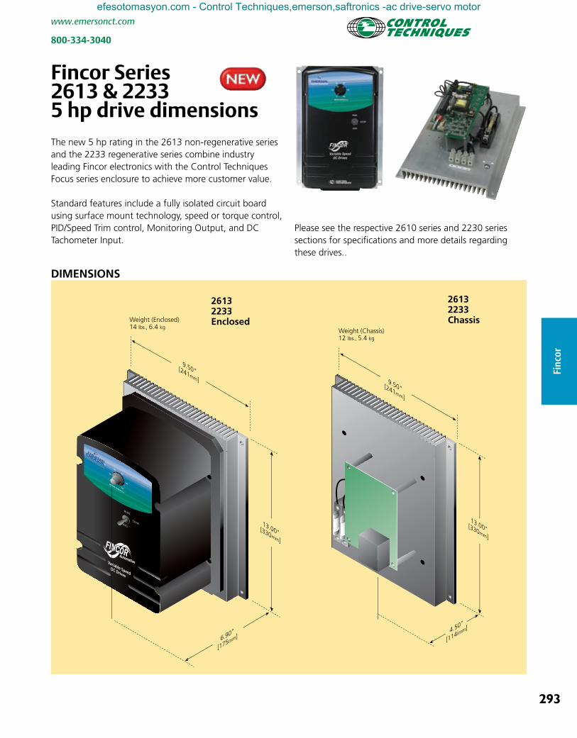
The new 5 hp rating in the 2613 non-regenerative series and the 2233 regenerative series combine industry leading Fincor electronics with the Control Techniques Focus series enclosure to achieve more customer value.
Standard features include a fully isolated circuit board using surface mount technology, speed or torque control, PID/Speed Trim control, Monitoring Output, and DC Tachometer Input.
Please see the respective 2610 series and 2230 series sections for specifications and more details regarding these drives..
Fincor Series 2613 & 2233 5 hp drive dimensions
efesotomasyon.com - Control Techniques,emerson,saftronics -ac drive-servo motor

294
www.emersonct.com
800-334-3040
Fincor
Min Speed
+10V RefExt Current Ref Input
Current Common
Tachometer Fdbk InputRun Enable Input (+24 VDC)
+24 VDCRun Relay N.O. ContactsRun Relay N.O. Contacts
Controlled Stop Input
Speed Reg Node InputCur. (4 to 20 mA) Output Speed
Circuit Common0 to +10 VDC Output Speed
Zero Speed Output
Current Loop Follower Input
Speed Ref Input
Circuit Common
Circuit Common0 to +10 VDC Output Torque
Circuit Common
Cur. (4 to 20 mA) Output Torque
Speed Ref Pot
Torque Ref Pot
K
Controlled Stop
HalfWaveField
Motor Armature
4-20 mA
TERMINAL DIAGRAM: Series 2610
TERMINAL DESCRIPTION
Pin# Type Notes
L1 Line Voltage Input 115 or 230 VAC J1 Selectable
L2 Line Voltage Input 115 or 230 VAC J1 Selectable
F+ Field Voltage Output +100 VDC @ 115 VAC or +200 VDC @230 VAC Input
F/2 Field Voltage (Half-Wave) Output
+50 VDC @ 115 VAC or +100 VDC @230 VAC Input
F- Field Voltage Output Field Minus Output
A1 Armature + Output 0 to +90 VDC @ 115 VAC or 0 to +180 VDC @ 230 VAC Input
A2 Armature - Output Armature Minus Output
TB1 TB2
TB1
Pin# Type Notes
8 Enable Input (+24 VDC) – Run Relay
24 VDC @ 6 mA Input
9 +24 VDC For drive enable use only
10 Run Relay N.O. Contacts Form A Contact Rated 0.5A @ 115 VAC or 2A @ 30 VDC11 Run Relay N.O. Contacts
12 Controlled Stop Input (+24 VDC)
Momentary +24 VDC Input to Initiate Controlled (Ramp) to Stop
13 Zero Speed Indication Output Open Collector, Active Low, Rated 24 VDC @ 50 mA
14 Speed Regulator Node Input Speed Trim or External PID Input (Bypasses Accel/Decel Ramps)
15 Current Loop Output 4 to 20 mA – Speed (Arm Volts)
16 Current Loop Output 4 to 20 mA – Speed (Arm Volts)
17 Voltage Output 0 to 10 VDC – Speed (Arm Volts)
18 Voltage Output Common Isolated From Line – Can be connected to Earth
19 Current Loop Output 4 to 20 mA – Torque (Arm Amps)20 Current Loop
21 Voltage Output 0 to 10 VDC – Load (Arm Amps)
22 Voltage Output Common Isolated From Line – Can be connected to Earth
TB2Pin# Type Notes
1 Speed Reference Pot ‘0’ End With On-board Min Speed Pot Active
2 Speed Reference Input 200 KΩ Input Resistance
3 +10V Reference Output 5ma max
4 External Current Reference Input
Refer to DIP Switch SW3-2 (1 – 5 mA, 4 – 20 mA, 5 – 50 mA)
5 Circuit Common Isolated From Line – Can be connected to Earth
6 Current Loop Follower Input Refer to DIP Switch SW3-2 (1 – 5 mA, 4 – 20 mA, 5 – 50 mA)
7 Tachometer Input (Speed Feedback)
Polarity Insensitive for Reversing Applications (3-30 VDC, 31-175 VDC)
TB2 Continued
efesotomasyon.com - Control Techniques,emerson,saftronics -ac drive-servo motor
295
www.emersonct.com
800-334-3040
Finc
or
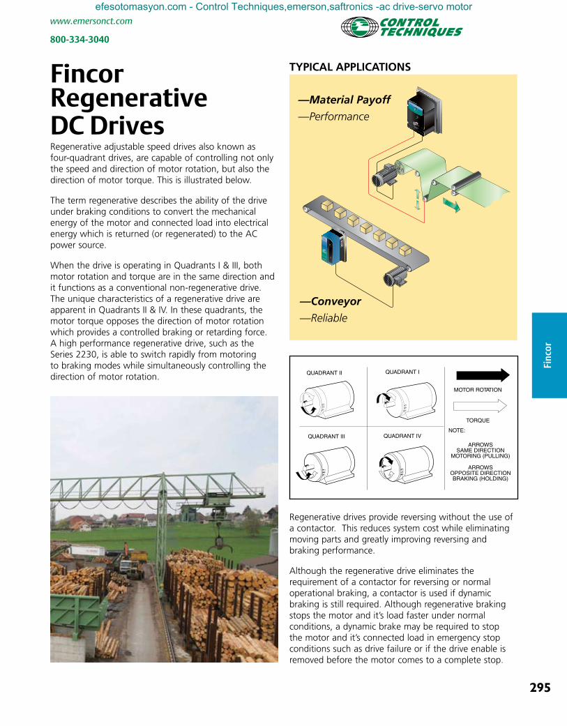
Fincor Regenerative DC Drives Regenerative adjustable speed drives also known as four-quadrant drives, are capable of controlling not only the speed and direction of motor rotation, but also the direction of motor torque. This is illustrated below.
The term regenerative describes the ability of the drive under braking conditions to convert the mechanical energy of the motor and connected load into electrical energy which is returned (or regenerated) to the AC power source.
When the drive is operating in Quadrants I & III, both motor rotation and torque are in the same direction and it functions as a conventional non-regenerative drive. The unique characteristics of a regenerative drive are apparent in Quadrants II & IV. In these quadrants, the motor torque opposes the direction of motor rotation which provides a controlled braking or retarding force. A high performance regenerative drive, such as the Series 2230, is able to switch rapidly from motoring to braking modes while simultaneously controlling the direction of motor rotation.
MOTOR ROTATION
TORQUE
NOTE:
QUADRANT I
QUADRANT III
QUADRANT II
QUADRANT IV
ARROWSSAME DIRECTION
MOTORING (PULLING)
ARROWSOPPOSITE DIRECTIONBRAKING (HOLDING)
—Material Payoff
—Performance
—Conveyor
—Reliable
TYPICAL APPLICATIONS
MOTOR SPEED (%)
0
20
100
80
40
60
RUN
JOG
STOP
RUN
JOGSTOP
2610
MOTOR SPEED (%)
Regenerative drives provide reversing without the use of a contactor. This reduces system cost while eliminating moving parts and greatly improving reversing and braking performance.
Although the regenerative drive eliminates the requirement of a contactor for reversing or normal operational braking, a contactor is used if dynamic braking is still required. Although regenerative braking stops the motor and it’s load faster under normal conditions, a dynamic brake may be required to stop the motor and it’s connected load in emergency stop conditions such as drive failure or if the drive enable is removed before the motor comes to a complete stop.
efesotomasyon.com - Control Techniques,emerson,saftronics -ac drive-servo motor

296
www.emersonct.com
800-334-3040
Fincor
Fincor Series 2230 regenerative drives are ideal for your more demanding application with ratings up to 5 horsepower. Regenerative drives handle reversing without contactors and are able to stop faster. They feature a fully isolated regulator using surface mount technology.
Open Chassis Bookcase
Fincor Series 2230
• 1/8 to 5 hp (115-230V) • Fully Isolated Regulator • Speed or Torque Control • 0-10 VDC or +/- 10 VDC Input Signal • PID / Speed Trim Control • Current Stability Adjust • Speed or Current Monitoring (0-10 VDC or 4-20 mA) • Fused Input • Line Start / Auto Restart Enable / Disable • Dual Field Supply • DC Tachometer Input • Diagnostic LED
RATINGS: 1/8 TO 5 hp (115-230 VAC)Series 2230 Regenerative DC Drives
Model MotorHP
Input Output Run-Stop- Jog *
Run-Stop-Jog, DB **
AC Volts Amps DC Volts Amps Order Code Order Code
Arm Field Arm Field
Chassis w/o Integral Operator Controls
1/8 - 1.0 115 15.8 90 50/100 10.5 1.02231 2231B
1/2 - 2.0 230 15.8 180 100/200 11.6 1.0
1/8 - 1.0 115 15.8 90 50/100 10.5 1.02232 2232B
1/2 - 3.0 230 22 180 100/200 15.1 1.0
1/8 - 1.0 115 15.8 90 50/100 10.5 1.02233 2233B
1/2 - 5.0 230 32 180 100/200 25 2.0
Book Case w/o Integral Operator
Controls
1/8 - 1.0 115 15.8 90 50/100 10.5 1.02235 2235B
1/2 - 2.0 230 15.8 180 100/200 11.6 1.0
1/8 - 1.0 115 15.8 90 50/100 10.5 1.02236 2236B
1/2 - 3.0 230 22 180 100/200 15.1 1.0
NEMA 4/12 w/o Operator Controls
1/8 - 1.0 115 15.8 90 50/100 10.5 1.02231P0 2231BP0
1/2 - 2.0 230 15.8 180 100/200 11.6 1.0
1/8 - 1.0 115 15.8 90 50/100 10.5 1.02233P0 2233BP0
1/2 - 5.0 230 32 180 100/200 25 2.0
NEMA 4/12 with Integral Operator
Controls
1/8 - 1.0 115 15.8 90 50/100 10.5 1.02231P1 2231BP1
1/2 - 2.0 230 15.8 180 100/200 11.6 1.0
1/8 - 1.0 115 15.8 90 50/100 10.5 1.02233P1 2233BP1
1/2 - 5.0 230 32 180 100/200 25 2.0
Units shipped calibrated for desired hp rating but jumpers can be adjusted for others. Units shipped ready for 230 VAC but may be reconnected for 115 VAC.
* Run-Stop-Jog with Static (Contactor-less) Reversing using -100 to 100% Speed Potentiometer ** Run-Stop-Jog with Armature Contactor and Dynamic Braking. Reversing uses -100 to 100% Speed Potentiometer
2230 Enclosed
efesotomasyon.com - Control Techniques,emerson,saftronics -ac drive-servo motor
297
www.emersonct.com
800-334-3040
Finc
or
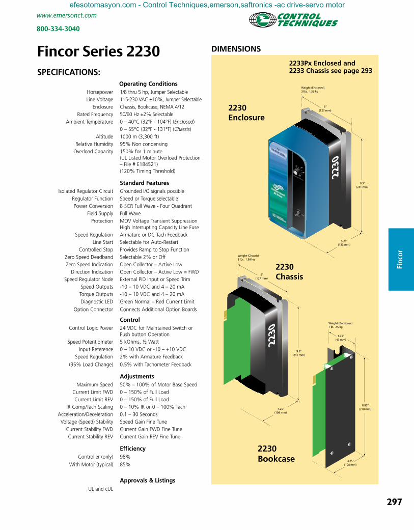
Fincor Series 2230 DIMENSIONS
2230 Enclosure
2230 Bookcase
2230 Chassis
RUN
JOGSTOP
5”(127 mm)
9.5”(241 mm)
5.25”(133 mm)
Weight (Enclosed)3 lbs. 1.36 kg
2230
MOTOR SPEED (%)
5”(127 mm)
9.5”(241 mm)
4.25”(108 mm)
Weight (Chassis)3 lbs. 1.36 kg
2230
1.75”(43 mm)
8.85”(218 mm)
4.25”(108 mm)
Weight (Bookcase)1 lb. .45 kg
SPECIFICATIONS: Operating Conditions Horsepower 1/8 thru 5 hp, Jumper Selectable Line Voltage 115-230 VAC ±10%, Jumper Selectable Enclosure Chassis, Bookcase, NEMA 4/12 Rated Frequency 50/60 Hz ±2% Selectable Ambient Temperature 0 – 40°C (32°F - 104°F) (Enclosed) 0 – 55°C (32°F - 131°F) (Chassis) Altitude 1000 m (3,300 ft) Relative Humidity 95% Non condensing Overload Capacity 150% for 1 minute (UL Listed Motor Overload Protection – File # E184521) (120% Timing Threshold)
Standard Features Isolated Regulator Circuit Grounded I/O signals possible Regulator Function Speed or Torque selectable Power Conversion 8 SCR Full Wave - Four Quadrant Field Supply Full Wave Protection MOV Voltage Transient Suppression High Interrupting Capacity Line Fuse Speed Regulation Armature or DC Tach Feedback Line Start Selectable for Auto-Restart Controlled Stop Provides Ramp to Stop Function Zero Speed Deadband Selectable 2% or Off Zero Speed Indication Open Collector – Active Low Direction Indication Open Collector – Active Low = FWD Speed Regulator Node External PID Input or Speed Trim Speed Outputs -10 – 10 VDC and 4 – 20 mA Torque Outputs -10 – 10 VDC and 4 – 20 mA Diagnostic LED Green Normal – Red Current Limit
Option Connector Connects Additional Option Boards
Control Control Logic Power 24 VDC for Maintained Switch or Push button Operation Speed Potentiometer 5 kOhms, ½ Watt Input Reference 0 – 10 VDC or -10 – +10 VDC Speed Regulation 2% with Armature Feedback
(95% Load Change) 0.5% with Tachometer Feedback
Adjustments Maximum Speed 50% – 100% of Motor Base Speed Current Limit FWD 0 – 150% of Full Load Current Limit REV 0 – 150% of Full Load IR Comp/Tach Scaling 0 – 10% IR or 0 – 100% Tach Acceleration/Deceleration 0.1 – 30 Seconds Voltage (Speed) Stability Speed Gain Fine Tune Current Stability FWD Current Gain FWD Fine Tune Current Stability REV Current Gain REV Fine Tune
Efficiency Controller (only) 98%
With Motor (typical) 85%
Approvals & Listings UL and cUL
2233Px Enclosed and 2233 Chassis see page 293
efesotomasyon.com - Control Techniques,emerson,saftronics -ac drive-servo motor
298
www.emersonct.com
800-334-3040
Fincor
Circuit Common
+10V Ref-10V Ref
Ext Current Ref Input FWD
Tachometer Fdbk InputRun Enable Input (+24 VDC)
+24 VDCRun Relay N.O. ContactsRun Relay N.O. Contacts
Controlled Stop Input
Speed Reg Node InputCur. (4 to 20 mA) Output Speed
Circuit Common-10 to +10 VDC Output Speed
Zero Speed Output
Ext Current Ref Input REV
Speed Ref Input
Direction Output
Circuit Common-10 to +10 VDC Output Torque
Circuit Common
Cur. (4 to 20 mA) Output Torque
Speed Ref Pot
TorqueRef PotFWD
TorqueRef Pot
REV
K
K
Controlled Stop
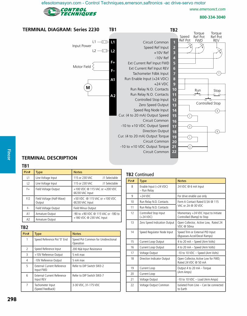
TERMINAL DESCRIPTION
Pin# Type Notes
L1 Line Voltage Input 115 or 230 VAC J1 Selectable
L2 Line Voltage Input 115 or 230 VAC J1 Selectable
F+ Field Voltage Output +100 VDC @ 115 VAC or +200 VDC @230 VAC Input
F/2 Field Voltage (Half-Wave) Output
+50 VDC @ 115 VAC or +100 VDC @230 VAC Input
F- Field Voltage Output Field Minus Output
A1 Armature Output -90 to +90 VDC @ 115 VAC or -180 to +180 VDC @ 230 VAC InputA2 Armature Output
TB1 TB2
TB1
Pin# Type Notes
1 Speed Reference Pot ‘0’ End Speed Pot Common for Unidirectional Operation
2 Speed Reference Input 200 KΩ Input Resistance
3 +10V Reference Output 5 mA max
4 -10V Reference Output 5 mA max
5 External Current Reference Input FWD
Refer to DIP Switch SW3-2
6 External Current Reference Input REV
Refer to DIP Switch SW3-7
7 Tachometer Input (Speed Feedback)
3-30 VDC, 31-175 VDC
TB2
TERMINAL DIAGRAM: Series 2230
Pin# Type Notes
8 Enable Input (+24 VDC) – Run Relay
24 VDC @ 6 mA Input
9 +24 VDC For drive enable use only
10 Run Relay N.O. Contacts Form A Contact Rated 0.5A @ 115 VAC or 2A @ 30 VDC11 Run Relay N.O. Contacts
12 Controlled Stop Input (+24 VDC)
Momentary +24 VDC Input to Initiate Controlled (Ramp) to Stop
13 Zero Speed Indication Output Open Collector, Active Low, Rated 24 VDC @ 50ma
14 Speed Regulator Node Input Speed Trim or External PID Input (Bypasses Accel/Decel Ramps)
15 Current Loop Output 4 to 20 mA – Speed (Arm Volts)
16 Current Loop Output 4 to 20 mA – Speed (Arm Volts)
17 Voltage Output -10 to 10 VDC – Speed (Arm Volts)
18 Direction Indicator Output Open Collector, Active Low for FWD; Rated 24 VDC @ 50 mA
19 Current Loop Output 4 to 20 mA – Torque (Arm Amps)20 Current Loop
21 Voltage Output -10 to 10 VDC – Load (Arm Amps)
22 Voltage Output Common Isolated From Line – Can be connected to Earth
TB2 Continued
efesotomasyon.com - Control Techniques,emerson,saftronics -ac drive-servo motor