flexible machine tool control for direct, in-process
TRANSCRIPT

Brigham Young University Brigham Young University
BYU ScholarsArchive BYU ScholarsArchive
Theses and Dissertations
2004-07-08
Flexible machine tool control for direct, in-process dimensional Flexible machine tool control for direct, in-process dimensional
part inspection part inspection
Tyler Addison Davis Brigham Young University - Provo
Follow this and additional works at: https://scholarsarchive.byu.edu/etd
Part of the Mechanical Engineering Commons
BYU ScholarsArchive Citation BYU ScholarsArchive Citation Davis, Tyler Addison, "Flexible machine tool control for direct, in-process dimensional part inspection" (2004). Theses and Dissertations. 139. https://scholarsarchive.byu.edu/etd/139
This Thesis is brought to you for free and open access by BYU ScholarsArchive. It has been accepted for inclusion in Theses and Dissertations by an authorized administrator of BYU ScholarsArchive. For more information, please contact [email protected], [email protected].

FLEXIBLE MACHINE TOOL CONTROL FOR DIRECT,
IN-PROCESS DIMENSIONAL PART INSPECTION
by
Tyler A. Davis
A thesis submitted to the faculty of
Brigham Young University
in partial fulfillment of the requirements for the degree of
Master of Science
Department of Mechanical Engineering
Brigham Young University
August 2004

BRIGHAM YOUNG UNIVERSITY
GRADUATE COMMITTEE APPROVAL
of a thesis submitted by
Tyler A. Davis
This thesis has been read by each member of the following graduate committee and by majority vote has been found to be satisfactory.
Date
Date
Date
W. Edward Red, Chair
C. Greg Jensen
Timothy W. McLain

BRIGHAM YOUNG UNIVERSITY
As chair of the candidate’s graduate committee, I have read the dissertation of Tyler A. Davis in its final form and have found that (1) its format, citations, and bibliographical style are consistent and acceptable and fulfill university and department style requirements; (2) its illustrative materials including figures, tables, and charts are in place; and (3) the final manuscript is satisfactory to the graduate committee and is ready for submission to the university library.
Date
Accepted for the Department
Accepted for the College
W. Edward Red Chair, Graduate Committee
Brent L. Adams Graduate Coordinator
Douglas M. Chabries Dean, Ira A. Fulton College of Engineering & Technology

ABSTRACT
FLEXIBLE MACHINE TOOL CONTROL FOR DIRECT,
IN-PROCESS DIMENSIONAL PART INSPECTION
Tyler A. Davis
Department of Mechanical Engineering
Masters of Science
For some time now coordinate measuring machines have been an integral part of the shop
floor. The goal has been to make coordinate measuring machines (CMMs) into tools that can
easily be used by machinists to improve their manufacturing capabilities. The value of a CMM as
a quality control tool is undisputed. Now efforts are being made to further reduce the time and
cost of measurement by reducing the physical distance between machining and measuring
processes. The ability to reduce that distance to zero and measure a part directly on the chip-
making machine has been a goal for many years.
Dimensional inspection of parts is primarily conducted by coordinate measuring
machines operating on motion instructions from task planning software. The research in direct
machining and control (DMAC) at BYU has identified a potential application of CMM
technologies on existing machine tools. To prove that a machine tool can be controlled as a
CMM with the DMAC controller, this research will integrate the software package PC-DMIS
provided by Wilcox Associates, Inc. with a DMAC controller provided by Direct Controls, Inc.
to conduct in-process dimensional inspection of parts as they are being machined. This process is
referred to as DirectCMM because it will link the DMAC controller directly to PC-DMIS
without need for post-processing. This thesis will lay the groundwork for future efforts at
developing systems that utilize in-process part inspection to dynamically correct computer aided
manufacturing (CAM) process plans.
To aid future efforts at dynamic CAM process updating, a software interface
specification will be created for passing measurement data between CMM and CAD/CAM
software packages. A CMM control specification will also be created to provide a standard
method for controlling coordinate measuring machines with the DMAC controller. Possible
methods for dynamic CAD/CAM updating will be explored.

ACKNOWLEDGEMENTS
Thanks go to BYU, Wilcox Associates, Inc., Direct Controls, Inc., and Sugino Machine,
Inc. for providing the software, hardware, and support necessary for completion of this thesis.
Special thanks are given for my wife and her support.
vii
TABLE OF CONTENTS
CHAPTER 1 Introduction..........................................................................................................1
1.1 Manufacturing Process ..........................................................................................................2
1.1.1 CAD/CAM Development ...............................................................................................2
1.1.2 Post Processing ...............................................................................................................4
1.1.3 Part Cutting .....................................................................................................................4
1.1.4 Part Inspection ................................................................................................................5
1.2 In-Process Inspection.............................................................................................................6
1.2.1 Advantages......................................................................................................................6
1.2.2 Disadvantages .................................................................................................................8
1.3 DMAC ...................................................................................................................................8
1.3.1 High Level Architecture .................................................................................................9
1.3.2 Device Driver Paradigm..................................................................................................9
1.3.3 COM Interface ..............................................................................................................11
1.4 DirectCMM..........................................................................................................................12
1.4.1 Connecting DMAC to PC-DMIS..................................................................................12
1.4.2 Development of Standard CMM Interface ...................................................................13

viii
1.4.3 Passing Measurement Data ...........................................................................................13
1.4.4 Future Efforts in Automatic Process Updating .............................................................13
CHAPTER 2 Literature Review...............................................................................................14
2.1 CMM Control Types............................................................................................................15
2.1.1 Hardware Control..........................................................................................................15
2.1.2 Microcomputer Control ................................................................................................16
2.1.3 Software Control ...........................................................................................................16
2.2 Current CMM Technology ..................................................................................................17
2.2.1 In-Process Inspection ....................................................................................................17
2.2.2 Dynamic Process Updating...........................................................................................20
2.2.3 Open-Architecture Controllers......................................................................................21
2.2.4 DMAC System..............................................................................................................23
2.3 Conclusion ...........................................................................................................................25
CHAPTER 3 Method—Connecting DMAC to PC-DMIS ......................................................27
3.1 Design Objectives ................................................................................................................27
3.2 Software Architecture ..........................................................................................................28
3.2.1 PC-DMIS ......................................................................................................................28
3.2.2 WADriver .....................................................................................................................33
3.2.3 WAILLDriver ...............................................................................................................36
ix
3.2.4 CMMInterface...............................................................................................................37
3.2.5 DMAC...........................................................................................................................39
3.3 Programming Strategies.......................................................................................................40
3.3.1 WADriver Setup ...........................................................................................................40
3.3.2 WAILLDriver Setup .....................................................................................................41
3.3.3 Test Tools......................................................................................................................42
3.3.4 Polling vs. Events..........................................................................................................52
3.3.5 Measurement Data Transfer..........................................................................................55
3.4 Hardware Configuration ......................................................................................................56
3.4.1 Sugino 3-Axis Mill .......................................................................................................57
3.4.2 Renishaw MP7 Probe....................................................................................................59
3.4.3 Renishaw OMM and MI12 ...........................................................................................60
3.4.4 DMAC Controller .........................................................................................................61
3.4.5 Installation Difficulties .................................................................................................61
CHAPTER 4 The Standard DMAC Interface for CMM .........................................................63
4.1 Interface Overview ..............................................................................................................63
4.2 Function Listing...................................................................................................................64
4.3 Programming Methods ........................................................................................................67
4.3.1 Create a New ATL/COM Project .................................................................................67

x
4.3.2 Create a DMAC COM Interface ...................................................................................68
4.3.3 Write CMM Execution Code ........................................................................................70
CHAPTER 5 Results................................................................................................................75
5.1 Interface ...............................................................................................................................75
5.2 Data Transfer .......................................................................................................................77
5.3 DirectCMM Control ............................................................................................................77
5.4 Coordinate Measuring Machine Tools ................................................................................79
5.5 Automatic Process Updating ...............................................................................................81
CHAPTER 6 Summary and Conclusions ................................................................................82
6.1 Overview of Problem and Solution .....................................................................................82
6.2 Contributions .......................................................................................................................83
6.2.1 Architectural Additions.................................................................................................83
6.2.2 Interface API .................................................................................................................83
6.2.3 Move-Until Motion Planning........................................................................................84
6.2.4 Interface to PC-DMIS ...................................................................................................84
6.2.5 Foundations for Future Research ..................................................................................84
6.3 Future Directions .................................................................................................................84
Bibliography……. .........................................................................................................................87
Appendix I—Programming Example ............................................................................................91

xi
LIST OF FIGURES
Figure 1-1 Typical CAD model with tool paths. .......................................................................3
Figure 1-2 Current machining process. .....................................................................................4
Figure 1-3 The device driver paradigm reduces the complexity in connecting
CMM process planning software to a device.........................................................................10
Figure 2-1 Hardware configuration with programmable logic control. ..................................15
Figure 2-2 Using a remote personal computer to integrate the probe system to
a CNC controller. ...................................................................................................................16
Figure 2-3 Software configuration with DMAC controller.....................................................17
Figure 2-4 A 3D solid model in Unigraphics. .........................................................................18
Figure 2-5 3D solid models can be directly imported into modern CMM software
such as PC-DMIS...................................................................................................................19
Figure 2-6 Current open-loop CMM use compared with proposed closed-loop use. .............21
Figure 2-7 DMAC system architecture....................................................................................24
Figure 3-1 Flow of information from PC-DMIS to DMAC. ...................................................28
Figure 3-2 Probe Utilities dialog used to define and edit measurement probe
models in PC-DMIS...............................................................................................................29
Figure 3-3 The Import Data dialog used to load CAD models into PC-DMIS. ......................30

xii
Figure 3-4 Creating an alignment in PC-DMIS.......................................................................31
Figure 3-5 Taking hits on a CAD model in PC-DMIS to measure a plane. ............................32
Figure 3-6 Typical DMIS file generated by PC-DMIS. ..........................................................32
Figure 3-7 Dialog used to execute a measurement program in PC-DMIS. .............................33
Figure 3-8 Standard driver configuration for PC-DMIS. ........................................................34
Figure 3-9 The open-architecture driver for PC-DMIS searches for predefined
functions that will control a CMM.........................................................................................35
Figure 3-10 The WAILLDriver separates PC-DMIS from the CMM controller
through a common interface. .................................................................................................36
Figure 3-11 The WAILLDriver connects with the DMAC controller through a
COM based plug-in called iCMM. ........................................................................................38
Figure 3-12 The iCMM interface is one of multiple COM-based control plug-ins
that can be used with DMAC.................................................................................................38
Figure 3-13 Overall architecture of DMAC. .............................................................................39
Figure 3-14 The debug log is enabled by setting the appropriate value as shown
above using the PC-DMIS settings editor..............................................................................42
Figure 3-15 The TestBox program used to test the WAILLDriver functions. ..........................43
Figure 3-16 Execution of the Machine_InManual() function returns a Boolean
result. True implies that the machine is currently in manual mode. ......................................44
Figure 3-17 Machine_GetMachineStatus has addition information returned
through variable pointers that are inputs to the function. ......................................................45
xiii
Figure 3-18 Dialog used to call and enter information for the
Machine_AutomaticallyMeasure function.............................................................................47
Figure 3-19 The iCMM interface will be created when starting the DMAC
controller if desired by selecting the appropriate check box. ................................................48
Figure 3-20 Communication between the CMM Interface and DMAC occurs
as needed with events. Communication between the CMM Interface and
PC-DMIS requires the use of a polling cycle. .......................................................................54
Figure 3-21 Information flows from the DMAC Controller to the machine tool
where the probe is mounted. Measurement information then returns to the controller. ........57
Figure 3-22 The Sugino V9. ......................................................................................................58
Figure 3-23 The Renishaw MP7................................................................................................59
Figure 3-24 The Renishaw MI12...............................................................................................60
Figure 3-25 The Renishaw OMM handles communication with the MP7 probe......................60
Figure 3-26 The adapter for the Sugino V9 is mounted to the top of the MP7 probe. ..............62
Figure 4-1 Creating a new COM project with Visual Studio 6.0. ...........................................67
Figure 4-2 Choosing the COM program type..........................................................................68
Figure 5-1 PC-DMIS running with DMAC.............................................................................76
Figure 5-2 Sugino mill measuring a part. ................................................................................78
Figure 5-3 Test measurement part. ..........................................................................................78
xiv
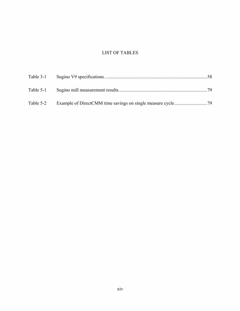
LIST OF TABLES
Table 3-1 Sugino V9 specifications. ......................................................................................58
Table 5-1 Sugino mill measurement results. ..........................................................................79
Table 5-2 Example of DirectCMM time savings on single measure cycle............................79

1
For some time now coordinate measuring machines have been an integral part of the shop
floor. The goal has been to make coordinate measuring machines (CMMs) into tools that can
easily be used by machinists to improve their manufacturing tolerances. The value of a CMM as
a quality control tool is undisputed. Now efforts are being made to further reduce the time and
cost of measurement by reducing the physical distance between machining and measuring
processes. For many years manufacturers have had the goal of reducing that distance to zero and
measuring a part directly on the chip-making machine.
Dimensional inspection of parts is primarily conducted by coordinate measuring
machines operating on motion instructions from task planning software. The research in direct
machining and control (DMAC) at BYU has identified a potential application of CMM
technologies on existing machine tools. To prove that a machine tool can be controlled as a
CMM with the DMAC controller, this research will integrate the software package PC-DMIS
provided by Wilcox Associates, Incorporated (WAI) with a DMAC controller provided by Direct
Controls, Incorporated (DCI) to conduct in-process dimensional inspection of parts as they are
being machined. This process is referred to as DirectCMM because it will link the DMAC
controller directly to PC-DMIS without need for post-processing. This thesis will lay the
CHAPTER 1 INTRODUCTION

2
groundwork for future efforts at developing systems that utilize in-process part inspection to
dynamically correct computer aided manufacturing (CAM) process plans.
To aid future efforts at dynamic CAM process updating, a software interface
specification will be created for passing measurement data between CMM, Computer-Aided
Design (CAD) and CAM software packages. A CMM control specification will also be created
to provide a standard method for controlling coordinate measuring machines with the DMAC
controller. Possible methods for dynamic CAD/CAM updating will be explored.
In-process inspection and its advantages can be more fully understood after a brief
introduction to the current methods for part manufacturing and inspection. This chapter will give
a short overview of the manufacturing process and its relation to in-process inspection. The basic
structure and advantageous capabilities of the DMAC motion controller will then be discussed.
Finally, the goals and tasks of this thesis will be explained.
1.1 Manufacturing Process
Current machine tool manufacturing technology consists of four main steps: CAD/CAM
part process development, post processing, part cutting, and part inspection. This section will
describe how these steps are completed.
1.1.1 CAD/CAM Development
Every manufacturable part starts out with an idea, or a set of specifications. From these
guidelines a part will be modeled in a 3D CAD/CAM (computer aided design / computer aided
manufacturing) package such as Unigraphics or ProE. The modeling phase of design allows the
designer to check for blatant design flaws and visualize the final product. In addition CAD

3
models are usually integrated with finite-element-analysis software to help with the functional
design of the part.
Once the part is modeled to the designer’s satisfaction, a process for cutting the part must
be developed. This consists of planning what machine tool and cutting tools will be used, and
planning the tool paths that the machine tool will follow. See Figure 1-1.
Figure 1-1 Typical CAD model with tool paths.
The tool paths that are created will necessarily be dependant on the type of machine tool
to be used (3-axis mill, 4-axis mill, lathe, etc.), due to the differing capabilities of each type of
machine tool. However, the tool paths will generally be independent of the brand or model of
machine tool selected. Due to the vast number of variations in machine tools, no current software
package is capable of knowing the physical capabilities and limits of each. As a result, the person
planning the manufacturing process must ensure that the plan does not violate any such
limitations.

4
1.1.2 Post Processing
At this point the generic plan is completed. The next step towards production is to create
commands that will instruct a specific machine to follow the tool paths that were created during
the CAD/CAM phase of design. This is generally a two step process. The first step converts the
tool paths to machine independent commands that are stored in a file using the Automatic
Programmed Tools (APT) format. This file is then read by a post-processor that converts the
APT commands to machine control data for a specific controller. The resulting file consists of
geometry and motion commands in the form of line commands commonly known as M&G code.
See Figure 1-2.
Figure 1-2 Current machining process.
M&G codes vary slightly among individual types of machine controllers. The variation
requires that a post-processor corresponding to each different machine controller be developed.
If a manufacturing plant has many different machine tools, a large number of post processors
must be made available for use by the process design software.
1.1.3 Part Cutting
Finally, the file containing the M&G data is loaded onto the specified machine tool, and
the process is allowed to run. If the resulting process has any errors, or if the part does not meet

5
specifications, the process plan must be modified. Simple modifications can be made by
manually editing the M&G file, while major process plan changes must generally be made by
revising the original CAD/CAM files and process plans. Any changes to the original plan will
require that a new M&G file be created through the post-processing procedure.
1.1.4 Part Inspection
It is necessary at times to measure a part to ensure that the manufacturing process is
producing acceptable results. Dimensional part inspection is primarily conducted by coordinate
measuring machines (CMMs). These machines provide a high degree of accuracy and precision
when measuring a part. Consequently, for the part to be measured it must be removed from the
machine tool and placed in the measuring machine, before any measurements can be made.
If the resulting measurements show that the part is outside of the tolerances given by the
designer, then the process must be modified to compensate for the manufacturing error. This
error can stem from worn tools, machine tool vibration, excessive heat, and a number of other
unpredictable environmental conditions. If the error is of a predictable nature, the process can be
modified to compensate for such error. However if the error is unpredictable, then each part must
be separately measured and corrected.
The advantages of out-of-process inspection relate directly to the advantages of part
measurement. By monitoring a part’s final dimensions a process engineer is able to track part
dimension trends and make corresponding process updates as needed. The benefits of part
process quality control are undisputed.
Disadvantages of out-of-process inspection are almost all related to expenses in time and
labor. Before measuring can begin a part must be removed from the cutting tool and placed on

6
the measurement machine. A measuring process plan that has been developed in a method
similar to the CAD/CAM process is then executed to measure the part. A process engineer must
analyze the resulting measurement data before any manufacturing process updates can be made.
If the part being manufactured was measured prior to the final cut, it will be re-fixtured in the
cutting machine, the process will be modified with the newly acquired measurement data, and
the final cuts will be made. Alternatively, if the part is being mass produced, measurements will
generally take place after the final cuts have been made. In this case, the process is modified to
account for the measurement data, and the updated process will be resumed to continue the
manufacture of acceptable parts.
1.2 In-Process Inspection
It is possible to measure a part while it is still fixtured on the cutting machine, using the
machine itself as a measurement device. This form of measurement is referred to as in-process
inspection, meaning that the measurement takes place as a step during the manufacturing
process. In-process inspection should not be confused with in-cycle inspection. In-cycle
inspection refers to measurement of either the part being manufactured, or a tool or other
manufacturing implement, during the actual cutting process. The advantages and disadvantages
of in-process inspection will be discussed in the following sections.
1.2.1 Advantages
There are numerous advantages associated with in-process inspection. Foremost among
them is CAM process updating. With measurement taking place on the same machine that is
performing the manufacturing operations, errors discovered through measurement can be
compensated by directly updating the process plan.

7
Another advantage of in-process inspection is the potential for reduced manufacturing
time. By measuring a part on the actual cutting machine the time and labor associated with
moving the part to the coordinate measuring machine and back is eliminated. This saves money
associated with operator labor, as well as reducing the time required by each machine during the
manufacturing process.
A general improvement in part tolerances can also be realized through in-process
inspection. By dramatically reducing the time and cost associated with part inspection, process
planners can measure every part manufactured before the final cut is made. By taking advantage
of the measurement data, it is possible to ensure that every part is manufactured to tolerances that
are at the maximum of the cutting machine’s capabilities.
In-process inspection can also reduce the additional operations required to reach the part
target dimensions. Rather than apply general or average measurement offsets to the overall
process plan, in-process inspection allows the offsets to be specific to each part being
manufactured. As a result, corrective post process operations can be reduced or eliminated
completely.
In-process inspection will lower manufacturing costs in a number of ways. Savings can
be obtained by eliminated the need for expensive specialized measurement machines. The
associated CMM operation and training costs will also be eliminated. Additionally, the time and
labor that would normally be used for measuring parts on a separate machine can be used for
other productive manufacturing responsibilities.
Reduced manufacturing costs can also stem from automatic fixturing and part alignment
performed by in-process inspection. By finding the exact location of a part prior to executing the

8
process plan, less work piece material allowance is needed. As a result, less material is used for
each part, and manufacturing savings are realized.
1.2.2 Disadvantages
One complication that is preventing most machine tools from adequately implementing
in-process inspection is the issue of machine control. In-process inspection requires unique
capabilities from the controller. Specifically, measurement commands such as moving until a hit
is detected must be performed by the controller. Most current machine tool controllers do not
include such capability, and modification of the controller to allow for such commands is
extremely difficult, if not impossible.
To fully take advantage of in-process inspection, it is necessary for the controller to
communicate with the controlling process to allow for modification and improvement of the
manufacturing process. This is out of the question for most controllers, since the controlling
process is simply a file of M&G commands, and no information about the part being
manufactured is present. In addition the controller has no logic or intelligence that will allow it to
take advantage of the measurement information it would obtain.
1.3 DMAC
The research in direct machining and control (DMAC) at BYU has provided a unique
solution to the shortcomings of typical machine tool controllers described above. The DMAC
controller is software-based and very flexible. As a result it is highly suited for integration with
the machine tool based measurement environment. This section will discuss the high-level
architecture of DMAC, its device driver paradigm, and its use of the COM standard for interface
implementation.

9
1.3.1 High Level Architecture
The first major difference with the DMAC controller is the method of motion input. In
place of the usual M&G style commands, the DMAC controller is given entity path information.
This can be in the form of position target moves, line moves, arc moves, or NURBS moves. As a
result, CAM packages are not required to tessellate complex curves into miniscule arcs and line
segments. This results in improved path accuracy, and provides the controller with complex path
planning and blending algorithms [1].
The path information is then passed to the trajectory generator, which is responsible for
planning the positions, velocities, and accelerations necessary for executing the path as quickly
and smoothly as possible. This path information is then converted to joint information and
checked against the machine’s physical capabilities and limits.
Once the desired joint information is determined, the servo control passes it to the actual
motors that drive the machine tool. The controller is directly connected to the motors via high-
speed fiber optic wires to allow for the control loop to be contained in the controlling software.
This allows for very flexible control and adaptability of the machine tool [2].
1.3.2 Device Driver Paradigm
The device driver paradigm is the concept of standardizing the interface for a particular
device. This eases the burden of programming specific control code for each machine that must
be controlled by allowing the software interface to remain the same for each different machine.
The controlling process can obtain information describing the capabilities of limitations of the
machine under control through this interface. It also sends all commands to this interface, and
10
retrieves results in the same way [3], [4], [5]. This opposes the current standard form of machine
control where a specific control interface must be used for each different machine under control.
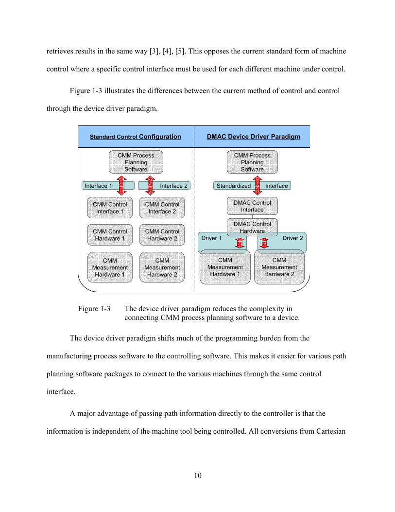
Figure 1-3 illustrates the differences between the current method of control and control
through the device driver paradigm.
Driver 2Driver 1
Standardized InterfaceInterface 2Interface 1
CMM Process Planning Software
CMM ControlHardware 2
CMM Control Interface 2
CMMMeasurementHardware 2
CMM Process Planning Software
DMAC ControlHardware
DMAC ControlInterface
CMMMeasurementHardware 1
CMM ControlHardware 1
CMM Control Interface 1
CMMMeasurementHardware 1
DMAC Device Driver ParadigmStandard Control Configuration
CMMMeasurementHardware 2
Figure 1-3 The device driver paradigm reduces the complexity in connecting CMM process planning software to a device.
The device driver paradigm shifts much of the programming burden from the
manufacturing process software to the controlling software. This makes it easier for various path
planning software packages to connect to the various machines through the same control
interface.
A major advantage of passing path information directly to the controller is that the
information is independent of the machine tool being controlled. All conversions from Cartesian

11
space to joint space are executed within the DMAC controller. As a result, applications such as
CAM packages are not required to perform post processing of the path data before execution.
1.3.3 COM Interface
The interface to the DMAC controller is accomplished using COM (Component Object
Model), a software-interfacing standard that allows various programs to communicate through a
common interface. COM specifications are such that the programming language used to write the
interface is independent of the interface itself. This way, any program that is written to COM
specifications is able to use the interface, regardless of the programming language used.
To allow process programs to connect to the DMAC controller a COM interface is
exposed to the computer environment. The specifications of the interface are also “published” to
the computer environment. Programs that need to connect to the DMAC controller and are aware
of the COM interface can then search the computing environment for the interface. Once found
the two processes open communications and the process planning software is able to use the
exposed functionality of the DMAC controller.
Another advantage of the COM specification is that changes are always backward
compatible. Once an interface is “published” its format may never change. This does not mean
however, that changes and improvements are forbidden. Revisions to a COM interface can be
made, and the revised interface is published as an entirely new interface. However, all of the
functionality contained in the previous interface must exist in the new interface. This allows an
older program to continue functioning properly if an improved interface is created.

12
1.4 DirectCMM
The marriage of the DMAC controller with current CMM technology in the form of
DirectCMM can lead to major improvements in the measurement environment. To prove that
DirectCMM is possible and advantageous, this thesis will describe a proof-of-concept
experiment. The four main areas of research to be addressed by this thesis are: connecting
DMAC to PC-DMIS, development of a standard CMM interface for DMAC, handling
measurement data, and future efforts in automatic process updating. These topics are described
below.
1.4.1 Connecting DMAC to PC-DMIS
The majority of work in the research for this thesis will be in interfacing PC-DMIS with
the DMAC controller. PC-DMIS, made by Wilcox Associates, Inc. is one of the most common
and well-accepted CMM process planning software packages available in the world. It is used by
many major manufacturing companies, and was recently acquired by Brown and Sharpe (makers
of CMMs). The developers at Wilcox Associates, Inc. (WAI) helped create an interface
compatible with the DMAC controller.
This thesis documents the implementation of a new DMAC COM interface for CMM
activities. A proof-of-concept was produced by mounting Renishaw measurement hardware,
(obtained with the help of WAI) to a Sugino 3-axis mill being controlled with the DMAC
controller. It is shown that the mill can be controlled in the form of a CMM directly from PC-
DMIS when using the DMAC controller.
13
1.4.2 Development of Standard CMM Interface
The work done in the research for this thesis has lead to the development of a
standardized CMM interface for the DMAC controller. The interface allows for any suitable
program to control DMAC in the mode of a CMM. The interface is documented to allow other
CMM software packages to make use of the DMAC controller and DirectCMM.
1.4.3 Passing Measurement Data
To use measurement data that is obtained with CMM process software, various control
processes must be able to communicate measurement information. This research has developed
and implemented methods for passing information between two separate control processes that
are simultaneously connected to the DMAC controller. Results and a description of the method
are included in this thesis.
1.4.4 Future Efforts in Automatic Process Updating
The next step in CMM process improvement is automatically updating a manufacturing
process with information obtained from in-process inspection. A brief review of current
automatic process updating techniques is included in this thesis. Alternate methods for process
updating are discussed and suggestions for future implementation efforts are made.

14
It is apparent that in-process inspection is a goal that many manufacturers are gravitating
towards. Checking the feature dimensions of a part prior to finish machining is normally only
available to the manual machine operator using calipers or some other measuring device. The
necessity of removing a part from the machine tool prior to measurement on a CMM, and then
re-fixturing in the machine tool for finish machining, is simply too time consuming to be of any
practical value to a manufacturer of mass produced parts. Integrating manufacturing and
measurement promises reduced cycle times, scrap reduction, optimized tool usage, improved
safety, and more accurate lead-time prediction [6].
As computer control of machinery becomes less expensive and more available, the
number of implementations and research programs aimed at applying the related advantages of
computer control to CMMs is growing. Despite the idea’s exciting possibilities, implementations
of the idea are limited by the technology currently available to the consumer. This chapter will
relate the current state of this technology.
CHAPTER 2 LITERATURE REVIEW

15
2.1 CMM Control Types
Currently many applications of in-process inspection are in use in industry. The methods
used to implement in-process inspection can be divided into three distinct types: hardware
control, remote microcomputer control, and software control.
2.1.1 Hardware Control
Simply put, this method uses an external programmable logic controller (PLC) to perform
measurement tasks during a production cycle. Control is temporarily transferred from the
machine tool controller to the PLC, which then performs the measurement tasks and returns a
result and control to the machine controller. While this type of solution is easy and cheap to
implement, it is inflexible and requires large amounts of setup time if changes are made to the
process plan [7]. See Figure 2-1.
ProbeInterface Relays
CNC ControllerControl Panel
ToolPosition
Workpiece
Probe
Figure 2-1 Hardware configuration with programmable logic control.

16
2.1.2 Microcomputer Control
This method is similar to hardware control in that during the measurement process
control is temporarily switched from the standard controller to a separate controller for CMM
movement. However, the PLC of hardware control is replaced by a much more flexible
microcomputer. This arrangement is shown in Figure 2-2. While this setup is much more flexible
than PLC control, it is still hampered by the necessity of multiple hardware connections and
difficult process coordination between various control systems. A working case study of this
method is discussed by Zhou et al. [7].
ProbeInterface
PersonalComputer
CNC MachineController
Machine ToolTable Logic Control System
Figure 2-2 Using a remote personal computer to integrate the probe system to a CNC controller.
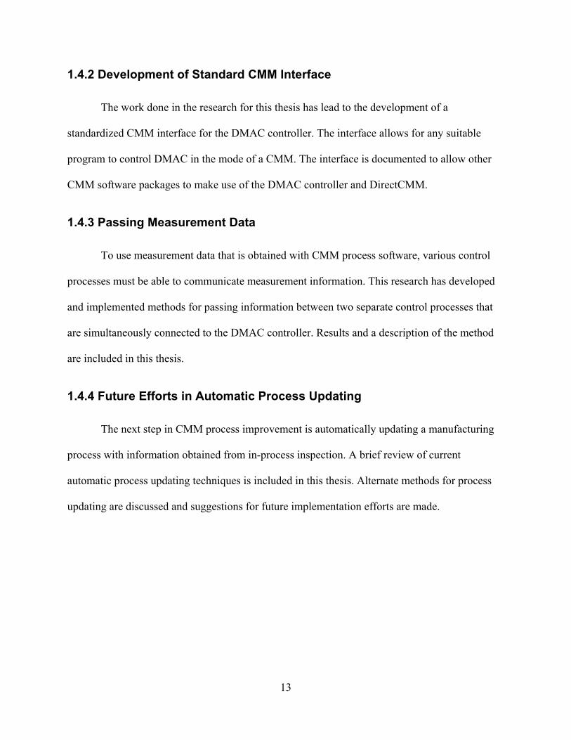
2.1.3 Software Control
The simplest and most flexible case is to use software control. In this case all of the
commands for machine control can be made available to the driving systems of both the
manufacturing process and the measurement process (see Figure 2-3). Typically, this option is
unavailable because control manufacturers do not provide programming APIs or any other
method of customization for the controller. DMAC is a perfect solution for this problem. The
DMAC controller is completely software-based and easily customized. In addition, Wilcox
Associates, Incorporated has recently expressed interest in developing a software-based generic
CMM driver for their PC-DMIS software package. Together, these two software packages
provide opportunities allowing for the software control case to become a reality.
17
ProbeInterface
DMAC Software BasedCNC Machine Controller
Machine ToolTable
CAD/CAM CMM
Figure 2-3 Software configuration with DMAC controller.
2.2 Current CMM Technology
The current state of technology in the CMM community will be discussed in this section.
In particular, four areas will be addressed: in-process inspection, dynamic process updating,
open-architecture controllers, and the DMAC system.
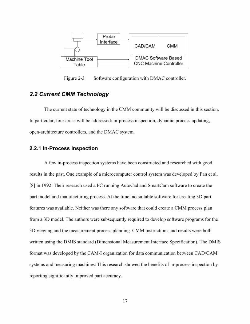
2.2.1 In-Process Inspection
A few in-process inspection systems have been constructed and researched with good
results in the past. One example of a microcomputer control system was developed by Fan et al.
[8] in 1992. Their research used a PC running AutoCad and SmartCam software to create the
part model and manufacturing process. At the time, no suitable software for creating 3D part
features was available. Neither was there any software that could create a CMM process plan
from a 3D model. The authors were subsequently required to develop software programs for the
3D viewing and the measurement process planning. CMM instructions and results were both
written using the DMIS standard (Dimensional Measurement Interface Specification). The DMIS
format was developed by the CAM-I organization for data communication between CAD/CAM
systems and measuring machines. This research showed the benefits of in-process inspection by
reporting significantly improved part accuracy.

18
Figure 2-4 A 3D solid model in Unigraphics.
Since then CAD/CAM software has improved dramatically in capability. Three-
dimensional solid model part creation and viewing is commonplace in CAD packages such as
Unigraphics, ProE, and Catia (see Figure 2-4). Solid modeling also allows for feature-based
modeling and parametric control of CAD models. CMM software has also greatly improved. PC-
DMIS is capable of creating CMM process plans in the DMIS format from solid CAD models
imported directly from common CAD packages, including Unigraphics, as well as from the
standard array of 3D model file formats such as IGES and STEP (see Figure 2-5).
19
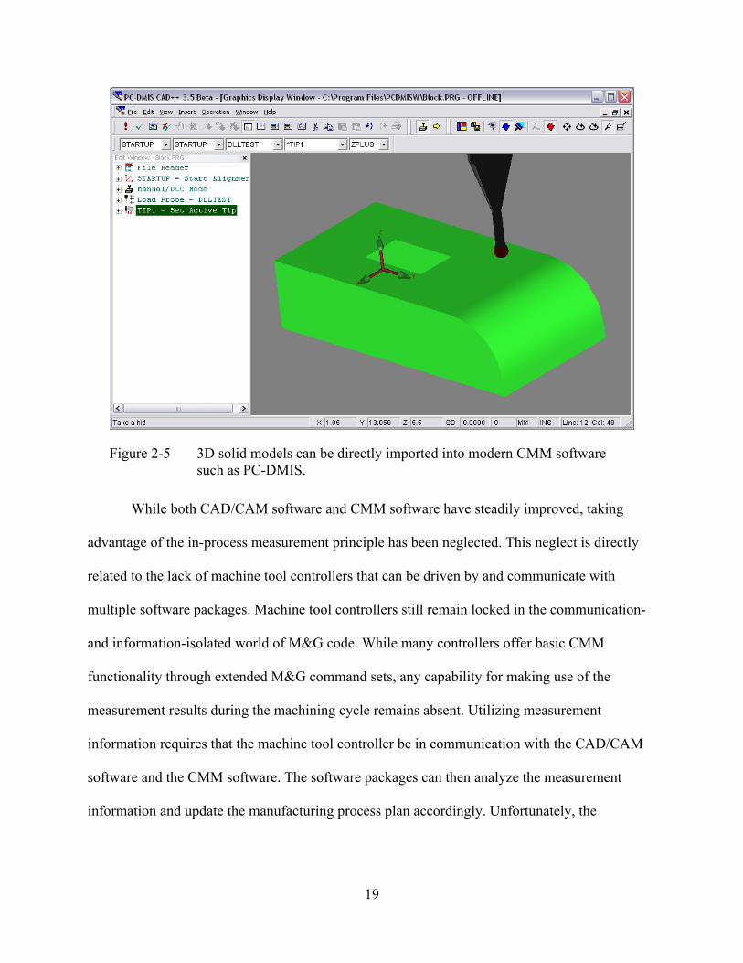
Figure 2-5 3D solid models can be directly imported into modern CMM software such as PC-DMIS.
While both CAD/CAM software and CMM software have steadily improved, taking
advantage of the in-process measurement principle has been neglected. This neglect is directly
related to the lack of machine tool controllers that can be driven by and communicate with
multiple software packages. Machine tool controllers still remain locked in the communication-
and information-isolated world of M&G code. While many controllers offer basic CMM
functionality through extended M&G command sets, any capability for making use of the
measurement results during the machining cycle remains absent. Utilizing measurement
information requires that the machine tool controller be in communication with the CAD/CAM
software and the CMM software. The software packages can then analyze the measurement
information and update the manufacturing process plan accordingly. Unfortunately, the
20
proprietary and hardware based nature of current machine tool controllers makes intelligent
communication with an external software package extremely difficult if not impossible.
In recent years the previously separate fields of CAD and CAM have been integrated
with software. Integrating CMM capabilities and software with CAD/CAM is the next logical
step toward a complete manufacturing software package. The financial and time related
advantages of process integration through software have been known for some time now
(Harrison et al. [9]). However, the technology to make such integration easily possible is not
readily available.
In-process inspection requires that sensors be attached to a machine tool. Sensor
technologies range from non-contact laser probing to the common Touch Trigger Probe (TTP)
systems. TTP systems have become the most commonly used sensors due to their flexibility and
low price [7], [10].
2.2.2 Dynamic Process Updating
The use of CMMs has progressed from a simple way to accurately check the work of an
individual operator to a tool that can be used for quality control applications, waste reduction,
and functional performance improvement. Integration with CAD provides dramatic
improvements in speed and quality for CMMs, but the one-way link achieves a small amount of
the potential that could be gained by a full dialogue between the systems. Such communication is
dependant on the open data transfer systems that do not currently exist in commercial controllers
[11].

21
CAMProcess
CMMProcess
CMMResults
? CAMProcess
CMMProcess
CMMResults
Open Loop Process Closed Loop Process
Figure 2-6 Current open-loop CMM use compared with proposed closed-loop use.
Methods for use of the measurement information are the current subject of research.
Cochran et al. [12] developed a method for describing error sources that are compensated by
adjustment in machining during setup and manufacturing. They also determine that significant
improvements can be made to cycle time, part location error, tooling error, and machine tool
calibration. However, no solution is offered for software or hardware that can close the loop
between part manufacturing and part measurement (see Figure 2-6). The desire for integrated
CMM and CAD/CAM control remains present, while a suitable solution has yet to be found.
2.2.3 Open-Architecture Controllers
Open-architecture controllers are only now beginning to be researched due to the
increasing performance capabilities of computers. Research efforts can be found in the principles
of open-architecture control (OAC) and manufacturing. Three active industrial consortiums, the
OSE [13] (Open System Environment for controller) of Japan, the OSACA [14], [15] (Open

22
System Architecture for Controls within Automation systems) of Europe, and the OMAC [16]
(Open Modular Architecture Controllers) consortium of the U.S., define and promote the use of
open-architecture controllers to replace the old closed CNC systems. In academia, several
research projects have been undertaken in an attempt to open CNC control. Wright et al. [17],
[18] proposed the MOSAIC (Machine Tool Open System Advanced Intelligent Controller)
architecture in 1988. Koren et al. [19] at the Engineering Research Center for Reconfigurable
Machining Systems at the University of Michigan proposed an open CNC system, named
UMOAC. Yellowley et al. [20] at the University of British Columbia proposed and developed a
UBC open-architecture controller.
Despite all of these efforts by industry and research institutes, to this day there is no
standard interface that is agreed on by all machine manufacturers, control vendors, software
developers, and machine tool end users. In addition, the lack of associativity between CAD
model, CAM system, CMM system, and CNC machine still remains as the greatest limitation in
these architectures.
While most OACs are developed for machine tool control, control for CMMs has not
been excluded entirely. Chang et al. have developed a software-based open-architecture
controller for CMMs that operates on a dedicated Pentium-based PC with a real-time operating
system [21]. Communication with the controller is accomplished using a TCP/IP link to a
separate computer dedicated for the user interface. The user interface computer can be used to
modify controller parameters, to send motion commands, and to record measurement data. While
flexible enough to support multiple probe types, this controller is lacking motion commands
capable enough for manufacturing use and so is limited to CMM control.
23
2.2.4 DMAC System
The DMAC system developed at BYU is the most thoroughly developed open-
architecture controller available. It offers many motion types, such as target and joint moves, and
path moves that can be defined by lines, arcs, or NURBS. The open-architecture allows
programmers to connect the DMAC system with any software package that can issue suitable
move commands.
The hardware system consists of a PC with dual Pentium processors. The non real-time
Windows CAD/CAM application runs on one processor and all real-time applications, such as
motion control and servo loop control, run on the second processor (see Figure 2-7).
Sitting between the software-based DMAC controller and the physical digital drives and
I/O is a software layer called the Digital Control Interface (DCI). Evans et al. [2] discuss the
DCI. Currently, an ISA-bus card that connects to proprietary fiber optic lines forms a network
that is used to communicate between the software controller and the digital drives. A commercial
version uses an IEEE 1394 network. The modular structure of the system makes it easy to
replace the existing ISA card and fiber optic lines with any new PC communication cards and
protocols, such as PCI based fiber-optics, IEEE Fire wire 1394, or USB2.
Each distributed networked drive consists of a digital motor interface, an amplifier, and a
motor. Each drive is connected to the ISA-bus card through two fiber optic lines. The digital
motor interface receives torque set points from the software controller through one fiber optic
line. It converts the torque set point into an analog signal, which is then amplified to drive the
motor. Actual torque, position, velocity, and acceleration signals are sensed and put into digital
form to be relayed back to the software controller through the other fiber optic line.

24
CAD/CAM/CMM
Application
Process Plan
Current System Information
Commanded
Control Laws
I/O
Servo Controller
τ
Digital Control Interface
CPU-1Windows NT
CPU-2RTX
PC
Motion Planner
Direct Machining Interface
θ ,θ
TXX ,,
Figure 2-7 DMAC system architecture.
All of the control software is written in object-oriented C++ code. The software system is
divided into three layers - CAD/CAM/CMM application, Motion Planner, and Servo Controller.
The C++ language was used because it creates fast code that runs in the native language of the
computer. In addition, most CAD/CAM/CMM software systems provide C++ application
programming interfaces (APIs). These interfaces provide the opportunity for DMAC interfaces
to communicate with each software package.
The user interface or top layer of the DMAC system is a customized commercial
CAD/CAM or CMM application. With tool path data correctly prepared in the CAD/CAM or
CMM application, the real-time system (or second processor) gains access via the shared
memory queue of the Direct Machine Interface layer. The shared memory queue acts as a bi-
25
directional link between the two CPUs. It also allows a near real-time simulation of the actual
milling process back on the Windows CPU.
Motion commands and settings (coolant on/off, feed rate, spindle speed, etc.) are
generated in the Direct Machining Plug-in and are packed into motion or I/O data. This data will
then be passed to the Motion Planner through Direct Machine Interface. Red et al. discuss the
DMAC Motion Planner architecture in [4]. The Motion Planner is composed of a trajectory
generator and a kinematics object. An adaptive optimal trajectory generator [1] is used in our
architecture to generate position, speed, acceleration, and jerk values for each trajectory step,
based on a distance parameter such as total distance along a path. Each joint’s position, speed,
and acceleration can be found by calling an inverse kinematics routine. To drive a motor each
joint position, speed, and acceleration value must first be mapped into actuator space and then
converted into a torque set point. This torque set point is fed into the Servo Controller.
The Servo Controller [2] receives the torque set point from the Motion Planner and
performs the servo control functions for each actuator in the system. Currently, a feed forward
proportional-integral-derivative (PID) control law is implemented on the Servo Controller.
Because of the flexibility and modularity of our system architecture, any new servo control laws
can be easily implemented to replace the existing PID control.
2.3 Conclusion
While the need and the desire for an integrated CAD/CAM/CMM package is real, the
technology required for such integration has been unavailable until now. The DMAC system
offers capabilities sufficient for both manufacturing and CMM needs. The DMAC controller is
an open-architecture system that can easily communicate with any suitable software system.

26
Communication occurs with CAD packages such as Unigraphics as easily as with CMM
packages such as PC-DMIS.
The flexible nature of DMAC allows a manufacturing process to be easily interrupted for
a measurement cycle by allowing control of the machine tool to be switched from one software
package to another. In addition, the measurement information is readily available from the CMM
software to be utilized in a suitable manner for manufacturing process modification. Once the
manufacturing process has been updated, control is simply switched back to the CAD/CAM
software to allow completion of the cutting process.

27
To demonstrate the viability of in-process inspection with DMAC, a proof of concept
software package was developed. The proof of concept consists of a series of software
components that together allow PC-DMIS to control a CMM or another suitable machine
through DMAC. Development was performed using software simulation packages while final
testing was performed using an actual 3-axis machine tool. A description of the software
developed for this proof of concept is given in this chapter.
3.1 Design Objectives
Before any software package can be of any use, a set of inputs and outputs must be
defined. For this thesis, those inputs and outputs are defined by the requirements of the
individual software packages involved, as well as the overall objectives of the functioning whole.
Since DMAC is already a fully-functional machine tool controller, some additions must
be made to allow for CMM control. These changes relate mostly to adding the capabilities
required to handle measurement probe hardware. All of the functionality must then be exposed to
maintain the open-architecture of the DMAC controller.
In addition, other requirements are created by the interaction between multiple software
packages. The DMAC controller must be able to accept control commands from multiple
CHAPTER 3 METHOD—CONNECTING DMAC
TO PC-DMIS

28
sources, while maintaining control of the motions and position of the machine. The DMAC
controller must be able to coordinate the motion commands and communicate information
between itself and the various software packages that are currently connected to it.
The design objectives of this thesis were driven by the requirements outlined above. The
software architecture that was developed to satisfy these objectives will be discussed in the
following sections.
3.2 Software Architecture
The majority of this thesis is centered on the connection between PC-DMIS and DMAC.
A diagram of the steps between PC-DMIS and DMAC can be seen in Figure 3-1. This section
will describe each part of the information flow between PC-DMIS and DMAC in detail. The
software used to enable the information flow, and the development procedures used to create and
test the software will also be discussed.
Desktop Computer
PC-DMIS WADriver.dll WAILLDriver.dll iCMM DMAC
CMM
Figure 3-1 Flow of information from PC-DMIS to DMAC.
3.2.1 PC-DMIS
PC-DMIS is a software package that is used to write and execute CMM process plans. It
can easily create feature-based measurement commands, alignments, and motion commands. The
process plans can be written by actually moving a connected CMM to various positions and

29
measuring a master part, or by performing the same actions in a virtual manner with an imported
CAD model. The CAD model can be imported through a generic file format such as IGES or
STEP, or through a direct CAD interface that uses the built in file reading capabilities of a CAD
package. Once a process plan is completed, it is executed using PC-DMIS to control a CMM to
measure additional parts. A report of the measurement results are then stored in a file.
Figure 3-2 Probe Utilities dialog used to define and edit measurement probe models in PC-DMIS.
PC-DMIS uses the DMIS file format to store both the process plan program and the
measurement results. This file format is designed to be independent of the type of CMM being
controlled. All motion commands and feature descriptions are defined without using commands
that are specific to any particular machine. Part features are described explicitly in the DMIS file

30
and contain nominal dimensions and positions. This allows measurement results to be associated
with, and compared to, the specified feature dimensions.
To create a process plan, the user must first define a probe. This can be done using the
editing dialog shown in Figure 3-2. The probe model is necessary to describe achievable
measurement positions, and to compensate for any positional offsets from the end of the CMM
arm.
The next step in creating a process plan is to import a CAD model. PC-DMIS offers
many methods for importing a model, and is capable of reading generic 3D file formats such as
IGES and STEP. At the time of this research, the most reliable method for importing models
from Unigraphics NX was to use the file conversion capability included in PC-DMIS. This
method does not actually use the UG file reading capabilities, but converts the UG file into a
format that PC-DMIS can understand. See Figure 3-3.
Figure 3-3 The Import Data dialog used to load CAD models into PC-DMIS.
Once the file is imported, the part must be located relative to the machine through the use
of a part alignment. The alignment is created by selecting various features on the imported CAD
model such as a plane, line, and point, to locate and orient a certain point. All other positions and

31
dimensions are measured from this defined point. The alignment procedure can be seen in Figure
3-4.
Figure 3-4 Creating an alignment in PC-DMIS.
Using the above method, routines for measuring individual features can now be created.
PC-DMIS automates this process by allowing the user to pick the type of feature to be
measured—a line, plane, or circle for example—and then selecting the associated feature to be
measured on the imported CAD model. Once a feature is selected, nominal feature dimensions
can be determined by reading the CAD model. Features often require the user to specify
locations for measurement hits, as well as various parameters such as the clearance plane,
measurement retract distance, and measurement speed. Figure 3-5 illustrates the process of
taking hits on a CAD model to define a feature measurement.

32
Figure 3-5 Taking hits on a CAD model in PC-DMIS to measure a plane.
As each feature is added to the process plan, PC-DMIS writes the DMIS code necessary
to perform each action in a measurement sequence. An example file is shown in Figure 3-6.
$$ $$DATE=10/14/2003 TIME=2:21:24 PMDMISMN/'Block',04.0$$ PCD_PART_PROGRAM: PC-DMIS for Windows generated DMIS file$$REV NUMBER : $$SER NUMBER : $$STATS COUNT : 1UNITS/MM,ANGDECINCLUD/DMIS,'PCD_DMIS_DEFINES.DMI'…
…SNSLCT/SA(TIP1)
F(PLN1)=FEAT/PLANE,CART,0,0,0,0,0,1MEAS/PLANE,F(PLN1),0ENDMES
ENDFIL$$ END OF MEASUREMENT FOR$$ PN=Block DWG= SN=$$ TOTAL # OF MEAS =0 # OUT OF TOL =0 # OF HOURS =00:00:00
Figure 3-6 Typical DMIS file generated by PC-DMIS.

33
While this example described the process of creating a measurement plan, programs can
be created with a real part in a similar manner. The only real difference being that the actual
machine is moved to physically measure a master part when defining the process plan in place of
measuring an idea CAD model.
The resulting DMIS file can then be used to control the CMM when the user desires to
measure a new part. This is done simply by opening the same process file with PC-DMIS in a
mode that allows it to communicate with the connected CMM. The user clicks the execute
button, and the measurement process is carried out (see Figure 3-7). Measurement results are
then stored in an accompanying DMIS file for the user to read and analyze.
Figure 3-7 Dialog used to execute a measurement program in PC-DMIS.
3.2.2 WADriver
In order for PC-DMIS to operate in a generic domain—that is, not in a manner to fulfill
specific requirements of a particular CMM—it must issue all commands and receive all
responses in a generic format. However, in reality each particular CMM that PC-DMIS could

34
hope to control is indeed different and will assuredly have unique control syntax. It may be that
one CMM requires different command formats than another. Or perhaps one CMM
communicates with the computer via a serial port, while another uses a proprietary control card.
To allow the various communication protocols to interact with PC-DMIS, it is necessary to build
a device driver specific to each CMM. The device driver acts as interpreter between the generic
commands issued by PC-DMIS and the machine specific commands expected by any particular
CMM as shown in Figure 3-8.
Desktop Computer
PC-DMIS
CMM Driver
CMM
CMMController
Figure 3-8 Standard driver configuration for PC-DMIS.
Upon starting PC-DMIS, the user can select between two CMM connection modes:
online and offline. PC-DMIS will connect to the CMM when started in online mode, and will not
connect when in offline mode. When offline, the user is able to define probes, import CAD data,
and do other tasks necessary to create measurement programs. In online mode, the user is able to
do all of the same tasks that are available in offline mode, and can also create measurement
programs based on actual parts that are measured with the CMM. In addition, in online mode one
can execute available programs to measure a new part and report the results.
When starting in online mode, PC-DMIS connects to the CMM by searching for a file
named “interfac.dll” within its program directory that will act as the device driver for the CMM.
PC-DMIS includes drivers that will function with the majority of CMMs available to industry

35
such as Faro, and Leica, etc. but by default no particular driver is called “interfac.dll”. The user
is able to select which driver PC-DMIS will use simply by renaming the appropriate driver file to
“interfac.dll”.
Desktop Computer
PC-DMIS
WADriver.dll
Control functions providedby CMM controller
CMM
CMMController
Figure 3-9 The open-architecture driver for PC-DMIS searches for predefined functions that will control a CMM.
While this method is flexible and effective, it requires that a driver file be created by the
software developers at Wilcox Associates Incorporated for each type of CMM that will be
controlled by PC-DMIS. To provide a more open-architecture for future CMMs, the developers
at Wilcox Associates Inc. have developed a generic software-based driver called
“WADriver.dll”. This generic driver communicates with PC-DMIS in the same manner as the
other drivers, but rather than connecting directly to a CMM it searches for a set of functions that
will provide control for the CMM. The functions required by this driver are extremely specific in
functionality and are described by a document provided by Wilcox Associates, Inc. In this way,
the driver provides an open-architecture interface that allows a developer of an open-architecture
controller (such as DMAC) to write a companion driver that will connect with PC-DMIS. The
information flow originally depicted in Figure 3-8 becomes open ended as shown in Figure 3-9.

36
The control functions provided by the CMM controller must be made available in an
application extension file called “WAILLDriver.dll”—meaning Wilcox Associates, Inc. Low-
Level Driver. Building a version of this file compatible with DMAC integrates many of the
previously mentioned goals for this thesis.
3.2.3 WAILLDriver
The low-level driver must expose certain functions to the WADriver to allow PC-DMIS
to control the CMM. Since the low-level driver will be communicating with the controller in the
its native language, the syntax of the controller commands are irrelevant as long as the functions
exposed for PC-DMIS look and perform as described in the specification document provided by
Wilcox Associates, Inc. In this way the low-level driver separates the controller from PC-DMIS
while still allowing full inter-communication (see Figure 3-10).
WADriver.dll WAILLDriver.dll(Low-Level driver)
Open ArchitectureController
Written by PC-DMIS developers
Written by controller developers
Common interface
Figure 3-10 The WAILLDriver separates PC-DMIS from the CMM controller through a common interface.
In operation the driver also acts to reconcile incompatibilities between PC-DMIS and the
controller. For example, PC-DMIS does not assign identification numbers to each motion
command, but in DMAC each has a unique identification number. To account for this difference,
37
the low-level driver will automatically assign a move number to each move that is requested by
PC-DMIS before transferring the move data to DMAC.
While PC-DMIS and DMAC both recognize the same defining characteristics of a move,
the format in which they are described can vary significantly. The low-level driver exists to
account for these differences.
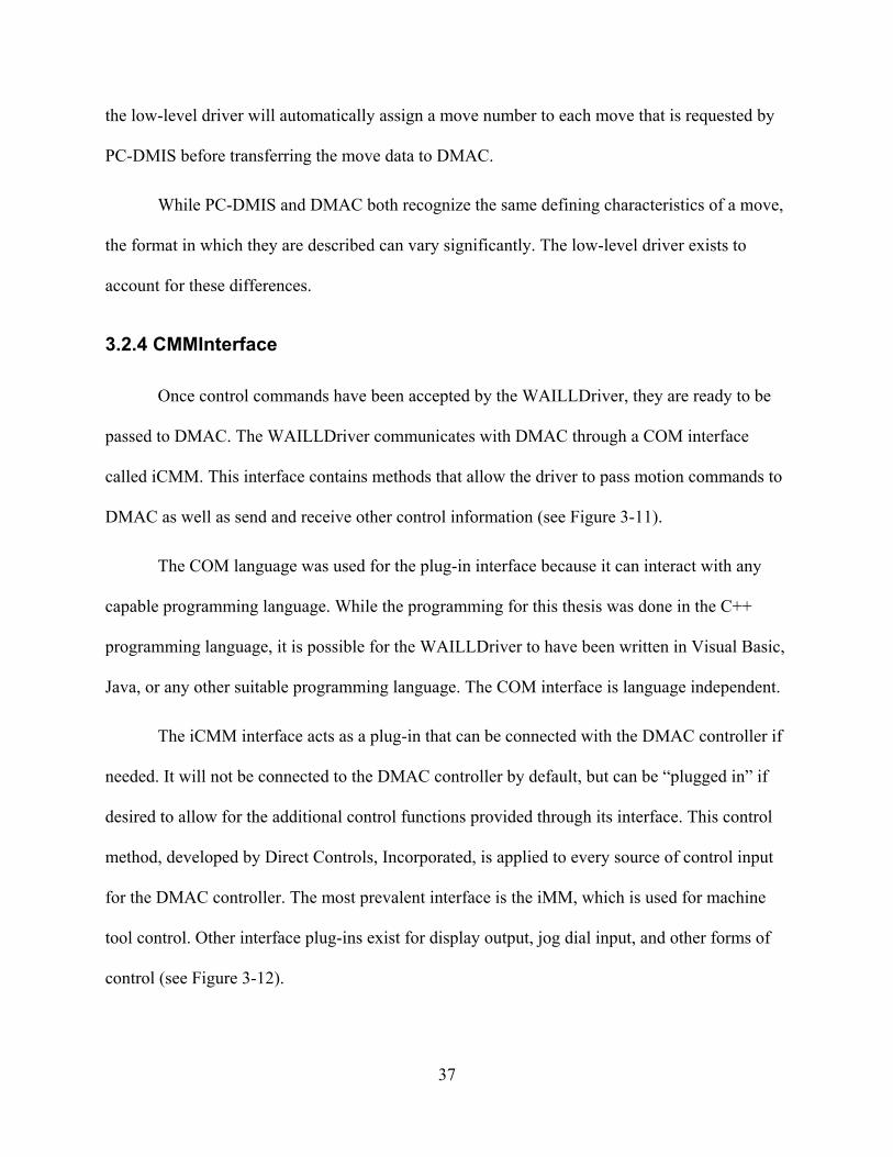
3.2.4 CMMInterface
Once control commands have been accepted by the WAILLDriver, they are ready to be
passed to DMAC. The WAILLDriver communicates with DMAC through a COM interface
called iCMM. This interface contains methods that allow the driver to pass motion commands to
DMAC as well as send and receive other control information (see Figure 3-11).
The COM language was used for the plug-in interface because it can interact with any
capable programming language. While the programming for this thesis was done in the C++
programming language, it is possible for the WAILLDriver to have been written in Visual Basic,
Java, or any other suitable programming language. The COM interface is language independent.
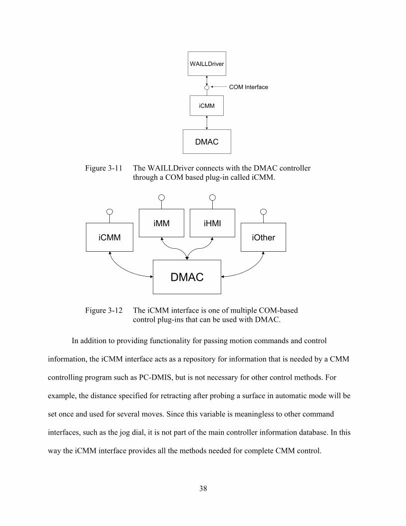
The iCMM interface acts as a plug-in that can be connected with the DMAC controller if
needed. It will not be connected to the DMAC controller by default, but can be “plugged in” if
desired to allow for the additional control functions provided through its interface. This control
method, developed by Direct Controls, Incorporated, is applied to every source of control input
for the DMAC controller. The most prevalent interface is the iMM, which is used for machine
tool control. Other interface plug-ins exist for display output, jog dial input, and other forms of
control (see Figure 3-12).
38
DMAC
iCMM
WAILLDriver
COM Interface
Figure 3-11 The WAILLDriver connects with the DMAC controller through a COM based plug-in called iCMM.
DMAC
iCMM
iHMI
iOther
iMM
Figure 3-12 The iCMM interface is one of multiple COM-based control plug-ins that can be used with DMAC.
In addition to providing functionality for passing motion commands and control
information, the iCMM interface acts as a repository for information that is needed by a CMM
controlling program such as PC-DMIS, but is not necessary for other control methods. For
example, the distance specified for retracting after probing a surface in automatic mode will be
set once and used for several moves. Since this variable is meaningless to other command
interfaces, such as the jog dial, it is not part of the main controller information database. In this
way the iCMM interface provides all the methods needed for complete CMM control.

39
3.2.5 DMAC
The DMAC controller is a software-based motion control package that has software
components running on two processors. One processor is operating in real-time to allow safe and
accurate motion control, while the other is operating in the usual non-real-time manner to handle
inter-process communication and the graphical user interface. The overall architecture of the
DMAC controller can be seen in Figure 3-13.
CAD/CAM/CMMApplication
Direct Machine Interface
Motion Planner
PC
CPU-1Windows NT
CPU-2RTX
τ
τ
θ θ’
I/O
ServoController
Digital Control Interface
Set Points CommandedX, X’, T
Digital Drives
Figure 3-13 Overall architecture of DMAC.
Once motion commands are received from a control interface, they are processed by the
motion planner. The motion planner is used to calculate velocity profiles and set points for each

40
axis (or motor) under control. Once the set points are determined, they are sent through the
digital control interface to the motors.
Since any command interface is equally valid, commands from any input can be handled
at the same time. If a machine is to be controlled by both a CAD/CAM package and a CMM
package, one package is paused and the current move buffer is stored. The other control package
then takes control until its tasks are complete. The first simply waits while the other drives the
machine. When the second package is done, the first move buffer of the motion controller is
restored to working order and the process continues as it was before the measurement.
3.3 Programming Strategies
The most difficult part to create in this series of software components was the
WAILLDriver. This was due to the fact that the driver handles communication between the PC-
DMIS and DMAC and must reconcile all differences in programming structure if the two are to
communicate properly. This section describes the problems encountered during the creation of
the DMAC compatible WAILLDriver and the methods used to overcome them.
3.3.1 WADriver Setup
Before the WADriver can be used successfully, it must be renamed to “interfac.dll”
within the PC-DMIS program files directory. After a standard installation of PC-DMIS the file
will be called WADriver.dll. Other drivers exist for the control of specific CMMs within the
same directory, while the WADriver exists for generic CMM control. By renaming the desired
driver file to “interfac.dll” the user is, in effect, specifying which driver PC-DMIS should use.

41
Since PC-DMIS sends motion commands to the DMAC controller, certain default motion
parameters must be set before the WADriver can be properly used. These parameters are:
• MoveAccelerationMax • MoveSpeedMax • TouchAccelerationMax • TouchSpeedMax
By default, these parameters are all set to zero and will cause PC-DMIS to command
moves of zero speed and zero acceleration. For this research the parameters were set to values
near 50 (i.e. 50 mm/s, and 50 mm/s2). These parameters are set by using a utility program
developed by PC-DMIS called “SettingsEditor.exe”. A picture of this program can be seen in
Figure 3-14.
If the user wishes to see debug output from the WADriver, the debug option must be set
appropriately as shown in Figure 3-14. By setting this parameter to true, PC-DMIS will create a
file called “debug.txt” within its program files directory. The name and location of the file can be
changed by the user.
3.3.2 WAILLDriver Setup
In order for the WAILLDriver to function properly, it must be stored in a directory that is
included in the system path of the computer. For this research, the file was placed in the
Windows\System32 folder. No other parameters or settings need to be initialized for proper
operation.

42
Figure 3-14 The debug log is enabled by setting the appropriate value as shown above using the PC-DMIS settings editor.
3.3.3 Test Tools
Two main difficulties existed in the programming of the WAILLDriver: First, the
interface was unchangeable. While some required functions easily pass simple information
between the two interacting programs, some functions do not lend themselves to being easily
implemented in the DMAC structure. However, if communication is to successfully occur
between PC-DMIS and DMAC they must fill the requirements of the interface specification. The
second difficulty is debugging the driver. The PC-DMIS program available to the public does not
include debugging symbols or code fragments that the developers of open-architecture

43
controllers can use to discover and resolve programming bugs and problems. As a result, it
became necessary that a separate application be built to test out the functionality of the low-level
driver.
Figure 3-15 The TestBox program used to test the WAILLDriver functions.
An application called “TestBox” was developed that could exercise each of the functions
exposed by the WAILLDriver to help debug the program. A picture of the TestBox application
can be seen in Figure 3-15.
The TestBox application simply calls functions that are exposed by the WAILLDriver
and displays the results of the called functions for the user to see. Functions are separated into
three groups: functions that require no input parameters, functions that require non-changing
inputs and functions that require specific changeable inputs. In addition, the TestBox can

44
simulate the probe’s response to hitting a part to test the functions that relate to events that occur
during the measurement process.
Figure 3-16 Execution of the Machine_InManual() function returns a Boolean result. True implies that the machine is currently in manual mode.
Functions with no parameters can be executed without needing to specify any input
information, or providing a variable for output data. The only function results come from the
function return value, which can be true or false. Figure 3-16 shows the results of the
Machine_InManual() function being called. This function simply returns true if the machine is
currently in manual mode and false if in automatic mode. The function results are displayed in
the text box area of the dialog. The provided functions with no input parameters are:
• Machine_OpenComms • Machine_SetCalibratedPartFrame • Machine_CloseComms

45
• Machine_InManual • Machine_InitCompensation • Machine_Home • Machine_StopNow • Machine_ManuallyMeasure • Machine_Scan • Machine_ReadWrist • Machine_EnterManualMode
Figure 3-17 Machine_GetMachineStatus has addition information returned through variable pointers that are inputs to the function.
Functions with non-changing inputs typically have an input point that can be used by the
function to store data. In this case TestBox results from both the function return value and the
input values are displayed for the user. For example, Figure 3-17 shows the return value of the
function, as well as the information that was stored in the variables that were made available to
the function through calling it. Functions available with non-changing inputs are:
• Machine_GetMachineStatus
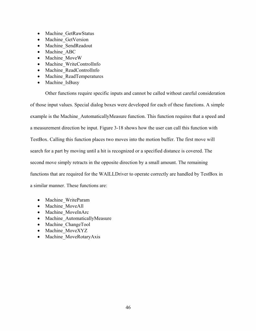
46
• Machine_GetRawStatus • Machine_GetVersion • Machine_SendReadout • Machine_ABC • Machine_MoveW • Machine_WriteControlInfo • Machine_ReadControlInfo • Machine_ReadTemperatures • Machine_IsBusy
Other functions require specific inputs and cannot be called without careful consideration
of those input values. Special dialog boxes were developed for each of these functions. A simple
example is the Machine_AutomaticallyMeasure function. This function requires that a speed and
a measurement direction be input. Figure 3-18 shows how the user can call this function with
TestBox. Calling this function places two moves into the motion buffer. The first move will
search for a part by moving until a hit is recognized or a specified distance is covered. The
second move simply retracts in the opposite direction by a small amount. The remaining
functions that are required for the WAILLDriver to operate correctly are handled by TestBox in
a similar manner. These functions are:
• Machine_WriteParam • Machine_MoveAll • Machine_MoveInArc • Machine_AutomaticallyMeasure • Machine_ChangeTool • Machine_MoveXYZ • Machine_MoveRotaryAxis

47
Figure 3-18 Dialog used to call and enter information for the Machine_AutomaticallyMeasure function.
Since the WAILLDriver is a dynamic link library, it is important to call all functions in
the same manner. For this program, all functions were called simply by referencing the function
name and relying on the library to find the function. This ensures that all functions will be
referring to the same copy in the memory address space of the library, and that no new copies
will be created for this program. It is important to call all of the functions from the same address
space to avoid creating multiple copies of library variables that affect function execution. For
example, the variable storing the initialization state of the driver could be different in separate
copies of the dll in memory if only one copy of the library was initialized. The multiple copies of
the library will function differently and cause error-prone behavior as a result. Avoiding this
problem requires only that the function calling the driver be consistent in its calling method.

48
3.3.3.1 Initialization
Before the WAILLDriver can be used the Machine_OpenComms() function must be
called. This function connects the driver to the iCMM interface for DMAC. Once
communication between the interfaces is established, a variable is set declaring that the driver is
initialized. All other function calls check this variable before completing any action. If this
variable is not set, all other function calls will fail.
Figure 3-19 The iCMM interface will be created when starting the DMAC controller if desired by selecting the appropriate check box.
Only one copy of the iCMM COM interface is created. It can be enabled or disabled by
choosing whether to create the interface when starting up the DMAC controller (see Figure
3-19). Creating one copy avoids problems that can arise when multiple sources attempt to access
the controller at the same time. As a result, each program that desires to connect to DMAC
through the iCMM interface is given a handle to the same object. For example, both the TestBox
49
application and PC-DMIS can be running at the same time, using separate copies of the
WAILLDriver, but will be connected to the same copy of the iCMM interface.
When the interface is opened, the machine will attempt to switch on the measurement
probe. For the Renishaw MP7 probe being used for this research the switching is accomplished
by spinning the probe at 500 RPM for half of a second. This engages a centrifugal switch that
turns the probe on. When the measurement process is completed and the interface is closed, the
probe is spun again to switch it back off.
Once started, it is important to switch the DMAC user interface to part frame display
mode. Since all commands sent from PC-DMIS are in part frame coordinates, and all joint values
sent from DMAC are in whatever frame is currently being displayed, using part frame display on
the DMAC UI is essential to proper positioning.
3.3.3.2 Move Buffering
Since CMM control does not require the complex path generation and blending
techniques used in machining, PC-DMIS generally does not require advanced move buffering.
However, PC-DMIS will often send a series of commands containing both parameter changes
and motion commands without waiting for a particular machine state. To handle this situation, a
simple buffer was implemented using the standard C++ STL list class. All commands are stored
in the list when sent to the WAILLDriver. After storing the command, the driver checks to see if
any commands are currently being executed. If the machine is idle, the buffered command will
be executed. If the machine is busy, the buffered command simply waits. Upon the completion of
each buffered command, the driver will check to see if any more commands are waiting in the
buffer. If so, the next command is executed.

50
3.3.3.3 Automatic Measuring
Automatic measuring occurs frequently throughout a part measuring process plan. The
measurement command consists of two moves: the actual measurement move, and a retract
move. Before calling this function, the user must specify the search distance, and the retract
distance. The search distance describes how far the machine will move before assuming it has
missed the part, and the retract distance describes how far the machine will move back after
hitting a part. These values are set by calling the Machine_WriteParam function prior to calling
the Machine_AutomaticallyMeasure function. Once they are set, they will remain unchanged
until overwritten by future calls to the function.
When calling the automatic measure function, the user inputs a speed and a target point
for the move. The DMAC controller then performs a directional step jog after determining the
direction based on the current position and the target point. The move will either end naturally
when the specified distance has been traveled, or will stop prematurely if a part is hit. A hit is
sensed by a signal that is sent from the measurement probe to the DMAC controller. When this
signal is received the DMAC controller will stop the current move. Receiving this signal will
then cause the iCMM interface to automatically add a retract motion command to move the
probe tip away from the part. To calculate the retract move, first the direction opposite of the
automatic measure’s direction is found. Then a point is located at the specified retract distance
away from the automatic measure’s target point along that direction. This allows that the
machine’s position after the retract move will not be affected by the actual location of the hit
point. Retracting to a known point allows following moves to start in the correct, predetermined
position.

51
A function to stop any current move was added to the DMAC controller to allow for
automatic measuring moves. Upon stopping the move it is imperative to correctly store the
current position parameters in the controller so that the following move can be correctly
calculated. Stopping the current move without clearing the move buffer is also potentially
dangerous. The next move could be expecting to start at the previously determined end point of
the current move. If this were to happen, a large instantaneous change in position would be
required, and would inevitably cause undesirable results. Accordingly, the function for stopping
the current move is not generally made available to controlling software packages. The iCMM
interface only allows its use if the current move is specified as an automatic measure move.
3.3.3.4 Manual Measuring
A conflict between DMAC and PC-DMIS existed in the way that PC-DMIS sends a
request for a manual hit. When requesting a manual hit, PC-DMIS requires that the
WAILLDriver switch into manual mode. It also expects that the request for a manual hit will be
handled in the same manner as a function that causes motion, such as
Machine_AutomaticallyMeasure. As a result, the driver will enter a mode where the machine is
considered “busy.” This executes a move until a hit is taken or the Machine_StopNow function is
called. In normal operation, PC-DMIS will cycle between requesting a manual measure and
calling Machine_StopNow to end the manual move.
The difficulty arose because a manual move does not actually cause motion directly; no
moves are immediately loaded into the motion buffer. With no moves in the buffer, the machine
was not considered busy, and PC-DMIS assumed that a hit had occurred to cause the end of the
manual move.

52
Solving this problem was a simple matter of keeping track of when a manual measure has
been requested within the iCMM module. If such a request has been made, the driver will
assume that it is busy until a hit is taken, or the measure is ended by a call to Machine_StopNow
even if no commands are actually stored in the command buffer.
3.3.4 Polling vs. Events
Two predominant software strategies exist that determine when an event has occurred.
The first is called polling. With this strategy the software checks or polls a list of variables for
their current status with a timed regularity. Certain actions will occur after each polling cycle
depending on the observed state of the variables. Changes to the variables may occur as a result
of functions that are called following the previous polling.
The downfall of polling is that as the list grows full of variables that must be checked, the
processing time required to complete the task can become excessive. In programming situations
where the processor time is a limited resource, another strategy must be used. The second
strategy is called “event handling”. With this strategy the main program simply waits until it is
notified of the occurrence of an event. When an event occurs, an interrupt is generated and sent
to the main program. The program then executes a block of code that has previously been
designated as the proper response to a particular event. This strategy relieves the main program
of the task of checking for every possible situation, and allows it to react only to the events that it
deems necessary, and only when those events occur.
Because the DMAC motion controller is software-based and must operate in real-time,
processor resources are extremely limited. The controller is accordingly built around the event
handling strategy. PC-DMIS, however, is built around the polling strategy. The difference

53
between the two software packages must be reconciled by the WAILLDriver. Some of these
differences are described below.
3.3.4.1 Checking the Machine Status
An obvious example of the differences between polling and event handling is the
Machine_IsBusy() function. This function is regularly called by PC-DMIS to monitor the status
of the CMM under control. For example, if PC-DMIS calls for an automatic measure move, any
subsequent calls to Machine_IsBusy() will return true until the automatic measure has
completed. By calling this function, PC-DMIS is able to determine when the move has finished,
and whether the machine is executing any other moves. Unfortunately, to implement this
function in a manner that communicates directly with the DMAC motion planner would require a
large number of time consuming function calls. This cannot be allowed since the processing time
reserved for the real-time portion of the controller is very limited.
Fortunately, a simple solution to this problem exists. The CMM interface of the DMAC
controller is able to maintain a variable that mirrors the state of the motion planner. This state
variable is only changed when an event is received from the motion planner. In the case of the
automatic measure move, the state variable is notified of each move command that is sent to the
motion planner. Then, as each move is completed, the motion planner will send an event stating
that the current move has completed. The CMM interface listens for these events and upon
receiving one will decrease the number of moves known to be executing, or in queue. As the
addition and completion of moves occurs rarely in comparison with the time spent processing a
move, the processing overhead for such notification is extremely low.

54
DMAC PC-DMISiCMM
Event-based communication
occurring as needed
Poll-based communication occurring at regularly timed
intervals
Figure 3-20 Communication between the CMM Interface and DMAC occurs as needed with events. Communication between the CMM Interface and PC-DMIS requires the use of a polling cycle.
Since the CMM interface software is executed on the non-real-time side of the DMAC
controller, repeated calls to it are costly but less critical. Calls to the Machine_IsBusy function
are simply answered by checking the current value of the state variable. The number of function
calls is minimized, the processing time is minimized, and the differences between the event
strategy and polling strategy are accounted for. See Figure 3-20.
3.3.4.2 Probe Latching
Another good example of how the event strategy is used in DMAC is the method for
determining when and where a hit occurred while measuring. A typical polling system would
simply make regular checks of the I/O signal associated with the probe, and when it changed
would note the position. Again this strategy suffers from large processing time requirements. If
too much processor time is required the polling cycle must be slowed—resulting in less accurate
measurements.
When an I/O signal is changed in the event driven method of the DMAC motion planner,
a hardware interrupt is generated and certain code segments are executed as a result. The first bit
of code executed sends the event to the rest of the software system along with the current joint

55
values. As a result, at the instant the signal changed the joint values are available for use at the
same time the event is sent. This allows the CMM interface to store the joint values at the instant
the probe was tripped. Any probe over-travel that occurs as the machine slows to a stop after
tripping the probe will not be of consequence, since the measured joint values are already
recorded. Using the event driven method of communication, the DMAC architecture is able to
conserve processor time and enhance joint measurement accuracy simultaneously.
3.3.5 Measurement Data Transfer
The DMIS format was chosen as the best method for data transfer between measurement
programs and CAD programs due to its generic and comprehensive format. An excellent
description of the DMIS standard can be found on the CAM-I website—the DMIS regulating
body [22]:
The objective of the Dimensional Measuring Interface Standard (DMIS) is to provide a
standard for the bi-directional communication of inspection data between computer systems and
inspection equipment. The standard is a vocabulary of terms, which establishes a neutral format
for inspection programs and inspection results data.
While primarily designed for communication between automated equipment, DMIS is
designed to be both man-readable and man-writable, allowing inspection programs to be written
and inspection results to be analyzed without the use of computer aids. With the enhancement of
the High Level Language extensions, DMIS can function and be implemented as a DME
(Dimensional Measuring Equipment) language.
DMIS provides the vocabulary to pass inspection programs to dimensional measuring
equipment and to pass measurement and process data back to an analysis, collection, and/or
archiving system. A piece of equipment which interfaces to others, using the DMIS vocabulary,

56
may do so directly or it may have a pre-processor to convert its own native data formats into the
DMIS format and/or a postprocessor to convert the DMIS format into its own data structure.
In essence, the DMIS file format can be used to describe a measurement program, as well
as the measurement results. Each measurement command is associated with a unique part feature
that can be directly associated with part features within a CAD/CAM package. Resulting
measurements are also directly associated with the part features. The feature association allows
various software packages to easily read and utilize the information stored within this file. PC-
DMIS takes advantage of this format and uses it to write all of its measurement programs and
measurement results.
By using the DMIS format, the results from measurements taken with DMAC and PC-
DMIS will lend themselves to easy use for future efforts in automated CAM process updating
regardless of which CAD/CAM package is used.
3.4 Hardware Configuration
A description of the hardware configuration used to test this system will be given here.
The overall connectivity between the probe and the DMAC controller can be seen in Figure 3-21.

57
DMAC Controller
Sugino V9
RenishawOMM
RenishawMI12
RenishawMP7
Figure 3-21 Information flows from the DMAC Controller to the machine tool where the probe is mounted. Measurement information then returns to the controller.
3.4.1 Sugino 3-Axis Mill
The physical mill used for this research is a Sugino V9 donated for research by Sugino
Machine, Inc. of Japan. It is used for research of the DMAC controller by Direct Controls, Inc.
Its use has been made available for the additional research related to the thesis. It is the first
commercial sized machine tool to be completely controlled by the DMAC controller. While its
workspace is limited to smaller parts, its speed and precision capabilities are impressive. The
Sugino V9 is shown in Figure 3-22, and its physical specifications are listed in Table 3-1.

58
Table 3-1 Sugino V9 specifications.
X-axis mm 200 Y-axis mm 200
Stroke
Z-axis mm 250 Working Area mm 300×500
Allowable Load kg 300 Table
Distance from table surface to spindle nose
mm 150~395
Spindle taper - NT20 Standard min-1 17,000 1.5kW
(Continuous rating)
Spindle
High speed min-1 22,000 1.5kW Rapid feed rate m/min 30 (X,Y,Z-axis)
Cutting feed rate m/min Max. 10 Feed
Min. programmable unit
mm 0.001
Positioning mm 0.006 (in full travel) AccuracyRepeatability mm ±0.003
Number of tools - 9 Tool to tool sec 0.7 Tool shank - JBS S20T (Pull stud
S20R-2) Max. tool dimension mm Ø32×160
Max. tool weight kg 0.5
ATC
Tool selection - Memory random Width × Length ×
Height mm 1100×2035×2150 Machine
Weight kg 1800 Power supply - 3PH200V±10%,50/60Hz
Power capacity kVA Max.20 Air pressure MPa 0.4~0.6
Power sources
Air consumption L/min(ANR) Max.90
Figure 3-22 The Sugino V9.

59
3.4.2 Renishaw MP7 Probe
The probe used for the testing during this research is a Renishaw MP7. A picture of the
MP7 is shown in Figure 3-23. This is an older probe made for use on machining centers. To
avoid complicated and expensive wiring, the probe uses optical signal transmission. It can be
mounted to a normal machine tool shank. If enough clearance is available, it can be mounted or
removed from the spindle using a machine tool’s automatic tool changer. The probe is switched
on by spinning it for a brief period of time. It is switched off in the same manner.
Figure 3-23 The Renishaw MP7.
The probe has graciously been made available for this research by the Precision Machine
Shop at BYU. Unfortunately the probe is quite large and will limit the size of measurable objects
that can be mounted without interference in the Sugino mill. However, the size limitation does
not affect the validity of the results from this research.

60
3.4.3 Renishaw OMM and MI12
The probe’s optical transmissions are interpreted by an optical transceiver called the
OMM (Optical Machine Module). The OMM in turn communicates with the signal processing
board called the MI12 (Machine Interface). The MI12 is shown in Figure 3-24.
Figure 3-24 The Renishaw MI12. Figure 3-25 The Renishaw OMM handles communication with the MP7 probe.
The OMM is mounted on the machine tool itself in a place that allows it an unobstructed
view of the probe at all times. Signals from the probe are received whenever the probe turns on
or off, or if the stylus is deflected from its neutral position far enough to “unseat” the probe (see
Figure 3-25). These signals are simply relayed to the MI12, which then converts the signals to a
form that can be recognized by a standard I/O module. The signals are passed to the DMAC I/O
module via wires, and are then used within the software system.

61
3.4.4 DMAC Controller
Each motor is controlled by an ORMEC ServoWire SM digital drive. Communication
between the DMAC controller and each motor drive is handled by the IEEE 1394 protocol. The
IEEE 1394 protocol can send information fast enough to allow control of multiple motors at rates
above 4000 Hz.
I/O connections are handled through an ICP DAS data acquisition system. The system
consists of a PCI card (model no: PIO-D48) that is mounted in the host computer and a daughter
board (model no: DB-24P) that connects to the PCI card and provides the I/O connections. All
communication to the I/O or the motor drives is handled by the VenturCom RTX Windows
subsystem. RTX is a real time subsystem that allows computers running a Windows operating
system to perform calculation in real time.
3.4.5 Installation Difficulties
Mounting the probe to a spindle shank compatible with the Sugino V9 was a cause of
some difficulty. Renishaw manufactures and sells shanks that will mount the MP7 probe, but all
of the shanks use tapers that are common to machine tools used in America. The Sugino
machines are not common within the United States, so finding shanks that match the S20T taper,
let alone S20T shanks that will accept an MP7, proved prohibitively difficult.
The solution was to make an adapter that would fit the MP7 probe to one of the tool
shanks that are currently used on the Sugino mill. The adapter was made from stainless steel by
the Research Machine Shop at BYU. It fits onto an existing tool shank by removing the collet
and collet securing nut from the shank and simply screwing the adapter on in place of the collet

62
nut. The MP7 then mounts directly to the adapter using screws as it would to a Renishaw-made
shank. The adapter is shown in Figure 3-26.
Figure 3-26 The adapter for the Sugino V9 is mounted to the top of the MP7 probe.
The length of the probe and adapter is a large portion of the Sugino’s work volume. As a
result, it was necessary to remount some of the fixturing within the Sugino mill’s workspace.
The Renishaw equipment was mounted to the Sugino mill with mounts manufactured for
the OMM and the MI12 to secure them in suitable locations to the mill itself. Power and signal
wires were then connected to the Renishaw equipment on the Sugino mill.

63
During the development of the driver files that interface between DMAC and PC-DMIS,
a set of functions were developed that provide all the functionality needed for communication
and control data to pass between the two programs. Those functions are equally applicable for
other programs that would connect to DMAC with the intent of controlling it in the manner of a
CMM. The resulting collection of functions collectively forms the standard DMAC interface for
CMM. This interface will be described in this chapter.
4.1 Interface Overview
All of the functions used to control the DMAC controller in the manner of a CMM are
made available through a single interface. This interface is a COM object that can be used by any
program that is running on the same computer as the DMAC controller. Such a program would
find the interface by searching a lookup table for a known identifying number called the Globally
Unique Identifier (GUID) that specifies the location of the interface object on the computer.
Once that location is determined, the program can connect to the interface and begin using its
functions.
CHAPTER 4 THE STANDARD DMAC
INTERFACE FOR CMM

64
To comply with the COM standard, each interface is given a name. For the CMM
interface the selected name is "IDMAC_CMM". Within this interface all of the functions for
CMM control are made available for any process wishing to use them.
4.2 Function Listing
A brief description of each function that is available in the IDMAC_CMM interface will
be given below.
CurrentPosition([out, retval] double pVal[5]); Assigns the machine’s current joint values to pVal.
LastHitPosition([out, retval] double pVal[5]); Assigns the machine’s joint values at the time of the last recorded hit to pVal.
NumMovesInBuffer([out, retval] long *pVal); Sets pVal equal to the number of moves currently stored in the DMAC motion buffer.
ControlMode([out, retval] long *pVal); Sets pVal equal to the current CMM control mode. Suitable values are: MODE_MANUAL MODE_AUTOMATIC_MOVE MODE_AUTOMATIC_MEASURE MODE_INACTIVE MODE_STARTUP MODE_SHUTDOWN
ControlMode([in] long newVal); Sets the current CMM control mode equal to the value of newVal.
Parameter([in] long ParamNumber, [out, retval] double *pVal); Sets pVal equal to the value of the control parameter defined by ParamNumber. Suitable values for ParamNumber are: MACH_PREHIT_DISTANCE MACH_SEARCH_DISTANCE MACH_RETRACT_DISTANCE MACH_SCAN_SPEED

65
Parameter([in] long ParamNumber, [in] double newVal); Sets the value of the control parameter specified by ParamNumber equal to newVal. Suitable values for ParamNumber are listed above.
DriverVersion([out, retval] BSTR *pVal); Sets pVal equal to the IDMAC_CMM interface version.
StatusMajorCode([out, retval] unsigned int *pVal); Sets pVal equal to the current value of the StatusMajorCode. Suitable values for StatusMajorCode are: MACHINE_SUCCESS MACHINE_ERROR
StatusMajorCode([in] unsigned int newVal); Sets the StatusMajorCode equal to newVal.
StatusMinorCode([out, retval] unsigned int *pVal); Sets pVal equal to the current value of the StatusMinorCode. Suitable values for StatusMinorCode are: MACHINE_ERR_UNKNOWN MACHINE_ERR_EMERGENCY_STOP MACHINE_ERR_NO_AIR MACHINE_ERR_TRAVEL_LIMIT MACHINE_ERR_SPEED_LIMIT MACHINE_ERR_ACCELERATION_LIMIT MACHINE_ERR_PROBE_NOT_ARMED MACHINE_ERR_SCALE MACHINE_ERR_PART_NOT_FOUND MACHINE_ERR_UNEXPECTED_HIT MACHINE_ERR_COMM_TIMEOUT MACHINE_ERR_RESPONSE_TIMEOUT MACHINE_ERR_INVALID_PARAMETER MACHINE_ERR_INVALID_PARAMETER_VALUE MACHINE_ERR_COMMAND_QUEUE_FULL MACHINE_ERR_UNSUPPORTED_OPERATION MACHINE_ERR_OTHER
StatusMinorCode([in] unsigned int newVal); Sets the StatusMinorCode equal to newVal.
Ok([out, retval] BOOL* pVal); Sets pVal equal to true if no errors have occurred on the machine, false otherwise.

66
NewHit([out, retval] BOOL* pVal); Sets pVal equal to true if a hit has occurred since the calling program lasted updated position values, false otherwise.
ProbeActive([out, retval] BOOL* pVal); Sets pVal equal to true if the probe is powered on and is communicating with the controller successfully.
Home([out, retval] BOOL* pVal); Sends all of the joints to their home position.
StopNow(); Stops a manual measure move, and clears the command buffer. This function should stop the machine as well, if possible.
MoveToXYZ([in] long MoveID, [in] double x, [in] double y, [in] double z, [in] double Speed, [out, retval] BOOL* pVal); Moves the machine to the specified X, Y, Z location at the input speed.
MoveRotaryAxis([in] long MoveID, [in] long JointNum, [in] double JointPose, [in] long Direction, [in] double Speed, [out, retval] BOOL* pVal); Moves the specified rotary axis to the specified position.
AutoMeasure([in] long MoveID, [in] double x, [in] double y, [in] double z, [in] double Speed, [out, retval] BOOL* pVal); Makes the machine move toward the specified point with the specified speed until a hit occurs. If a hit occurs, the machine will back up from the specified point in the opposite direction a distance that is specified by previous calls to the interface.
MoveInArc([in] long MoveID, [in] double x, [in] double y, [in] double z, [in] double CenterX, [in] double CenterY, [in] double CenterZ, [in] double i, [in] double j, [in] double k, [in] double Speed, [out, retval] BOOL* pVal); Moves the machine from it current position in an arc defined by the included parameters.
MoveAllAxis([in] long MoveID, [in] double Position[5], [in] double LinearSpeed, [out, retval] BOOL* pVal); Performs a joint move to the specified joint positions at the specified speed.
SendConditionChangedEvent([in] double JointValues[5], [in] long NumJoints, [in] unsigned __int64 Mask, [in] unsigned __int64 Condition, [out, retval] BOOL* pVal); Simulates a probe hit for use when the machine is offline.

67
SetCalibratedPartFrame(); Sets the current part frame such that all joint values read zero at the current position.
ManualMeasure(); Puts the machine into manual control mode and specifies that a probe hit is expected.
SpinProbe([in] double RPM, [in] double Seconds, [out, retval] BOOL* pVal); Used to switch the probe on or off by momentarily spinning the spindle.
4.3 Programming Methods
To use the iCMM interface, a program must create a COM object of the type iCMM. The
COM object can then be used as any other class object would be used in normal programming.
Since this thesis was completed using C++ and Microsoft Visual Studio 6.0, an example
measurement program created in Visual Studio is included below.
Figure 4-1 Creating a new COM project with Visual Studio 6.0.
4.3.1 Create a New ATL/COM Project
The simplest way to make a program COM compliant is to use the new project wizard in
Visual Studio to create the program structure automatically. Simply click File, New and then
select “ATL/COM AppWizard” as shown in Figure 4-1.

68
The wizard will then ask if the project should create a dynamic link library (dll) or an
executable (exe). For this example, an executable was created (see Figure 4-2).
Figure 4-2 Choosing the COM program type.
4.3.2 Create a DMAC COM Interface
The interfaces used in the DMAC program are handled differently from typical COM
interfaces in that the creation routines are handled by the DMAC code rather than standard code.
DMAC creates only one COM object with multiple connections to it when more than one
program connects to the COM interface. This differs from standard COM interfaces that simply
create multiple instances of the COM object. By using only one COM interface the DMAC
system avoids problems that can occur when multiple programs attempt to control DMAC.
A few header files must be included in the code to allow the use of the DMAC COM
interface system. They are DMACsubsystemids.h and CMMConstants.h. In addition, two
program files must be imported: wcm.exe and WCMPlugin_CMM.dll. This should be done as
shown below.

69
#include "DMACsubsystemids.h" #include "CMMConstants.h" #import "wcm.exe" no_namespace #import "WCMPlugin_CMM.dll" no_namespace
By including and importing these files, the COM project will have access to all of the
functions necessary for creating a COM interface with the DMAC system.
For the purpose of this example, a single function will perform all of the testing actions.
This function is _tWinMain(), which is the COM equivalent of a typical “Main” function. Visual
Studio has already created this function and filled it with some code to create a COM interface in
the typical manner. The pre-built code will be replaced with DMAC compatible code for this
example.
The first portion of the function, shown below, creates the COM interface.
// Make a pointer to the CMM interface IDMAC_CMM *g_pCMM = NULL; // Initialize COM on this thread HRESULT hres = CoInitializeEx(NULL, COINIT_MULTITHREADED); // Create the DMAC interface which will allow us to query for the CMM // interface IDMACPtr pDMAC = IDMACPtr(__uuidof(DMAC)); IDispatch* pDisp= NULL; if(pDMAC) { // Got the DMAC interface, now ask for the CMM interface pDMAC->get_PluginComInterface(SUBSYSTEMID_CMM, NULL,
(IDispatch**)&pDisp); if(NULL == pDisp) { MessageBox(NULL, _T("Don't have a CMM subsystem pointer!"),
_T("COMTest Error"), MB_OK|MB_ICONEXCLAMATION); return false; } else { HRESULT rVal = pDisp->QueryInterface(__uuidof(IDMAC_CMM),
(void**)&g_pCMM); if(NULL == g_pCMM)

70
{ // Couldn't create the CMM interface MessageBox(NULL, _T("Don't have a CMM interface
pointer!"), _T("COMTest Error"), MB_OK|MB_ICONEXCLAMATION);
return false; } } }
This above example code will vary only by how the errors are handled, and by the
variable names in a particular project, and should be copied as directly as possible when creating
a new CMM project.
This code now has a working COM object that accesses the DMAC CMM interface. The
DMAC system automatically handles the destruction of any connections to a DMAC COM
interface, so no further code need be devoted to the use of the COM interface.
4.3.3 Write CMM Execution Code
The remaining body of code will be used for the actual control of the machine as a CMM.
In this example, the machine simply moves to a point and the measures another point.
Methods for using probes vary among the many different measurement probes available.
Any code that satisfies the special needs of any particular probe, such as tool changing,
switching on probe power, or probe positioning, must be included at the beginning of a CMM
process. To switch the MP7 probe used during this research on or off, the spindle must be
accelerated to 500 rpm for about 1 second. When the probe switches on, its I/O signal will
change states from low to high. The example code below is written to simulate the probe’s
response so that the program can be executed without needing a physical machine for testing.
The DMAC CMM system must first be put into startup mode so that any signals from the
probe will not be considered erroneous. This is done with the following lines of code:
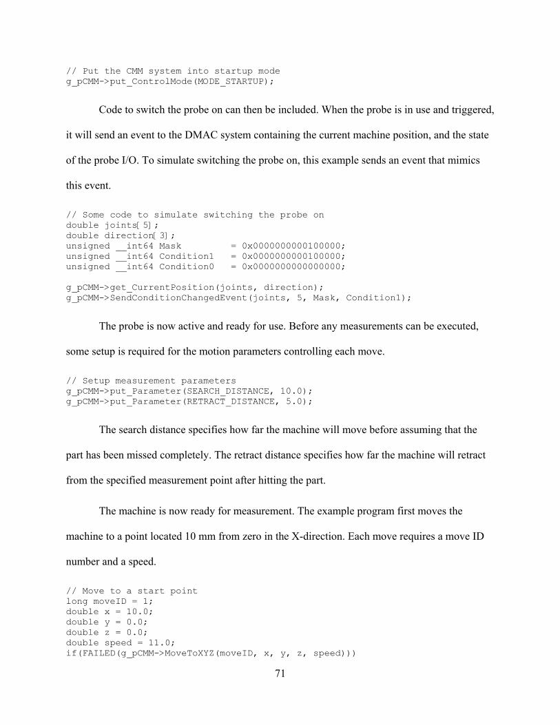
71
// Put the CMM system into startup mode g_pCMM->put_ControlMode(MODE_STARTUP);
Code to switch the probe on can then be included. When the probe is in use and triggered,
it will send an event to the DMAC system containing the current machine position, and the state
of the probe I/O. To simulate switching the probe on, this example sends an event that mimics
this event.
// Some code to simulate switching the probe on double joints[5]; double direction[3]; unsigned __int64 Mask = 0x0000000000100000; unsigned __int64 Condition1 = 0x0000000000100000; unsigned __int64 Condition0 = 0x0000000000000000; g_pCMM->get_CurrentPosition(joints, direction); g_pCMM->SendConditionChangedEvent(joints, 5, Mask, Condition1);
The probe is now active and ready for use. Before any measurements can be executed,
some setup is required for the motion parameters controlling each move.
// Setup measurement parameters g_pCMM->put_Parameter(SEARCH_DISTANCE, 10.0); g_pCMM->put_Parameter(RETRACT_DISTANCE, 5.0);
The search distance specifies how far the machine will move before assuming that the
part has been missed completely. The retract distance specifies how far the machine will retract
from the specified measurement point after hitting the part.
The machine is now ready for measurement. The example program first moves the
machine to a point located 10 mm from zero in the X-direction. Each move requires a move ID
number and a speed.
// Move to a start point long moveID = 1; double x = 10.0; double y = 0.0; double z = 0.0; double speed = 11.0; if(FAILED(g_pCMM->MoveToXYZ(moveID, x, y, z, speed)))

72
{ MessageBox(NULL, "MoveToXYZ::Failed.", "COMTest error",
MB_OK|MB_ICONEXCLAMATION); return false; }
Once the machine has reached that point, an automatic move is executed in the negative
X-direction.
// Do an automatic move moveID = 2; x = 5.0; if(FAILED(g_pCMM->AutoMeasure(moveID, x, y, z, speed))) { MessageBox(NULL, "AutoMeasure::Failed.", "COMTest error",
MB_OK|MB_ICONEXCLAMATION); return false; }
The measurement direction is calculated by determining the direction from the current
point to the specified measurement point. The following automatic retract move will be
calculated from the specified measurement point even if the actual measured point is in a
different location.
For the purpose of simulation, this example program gives the user the option of
simulating a hit, or letting the machine miss the part (no hit).
// Simulate a hit int retVal = MessageBoxEx(NULL, "Simulate a hit?", "COMTest question",
MB_YESNO, 0x0409); if(IDYES == retVal) { g_pCMM->get_CurrentPosition(joints, direction); g_pCMM->SendConditionChangedEvent(joints, 5, Mask, Condition0); //
Simulates probe hit g_pCMM->SendConditionChangedEvent(joints, 5, Mask, Condition1); //
Simulates probe reseating }
The program sends an event mimicking the probe I/O switching off, and then back on, as
the MP7 does in normal operation. The program can then check to see if a hit has occurred.
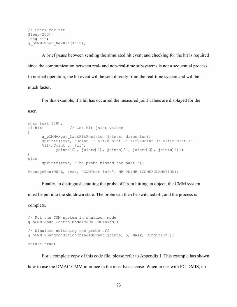
73
// Check for hit Sleep(200); long hit; g_pCMM->get_NewHit(&hit);
A brief pause between sending the simulated hit event and checking for the hit is required
since the communication between real- and non-real-time subsystems is not a sequential process.
In normal operation, the hit event will be sent directly from the real-time system and will be
much faster.
For this example, if a hit has occurred the measured joint values are displayed for the
user.
char text[100]; if(hit) // Get hit joint values { g_pCMM->get_LastHitPosition(joints, direction); sprintf(text, "Joint 1: %lf\nJoint 2: %lf\nJoint 3: %lf\nJoint 4:
%lf\nJoint 5: %lf", joints[0], joints[1], joints[2], joints[3], joints[4]); } else sprintf(text, "The probe missed the part!"); MessageBox(NULL, text, "COMTest info", MB_OK|MB_ICONEXCLAMATION);
Finally, to distinguish shutting the probe off from hitting an object, the CMM system
must be put into the shutdown state. The probe can then be switched off, and the process is
complete.
// Put the CMM system in shutdown mode g_pCMM->put_ControlMode(MODE_SHUTDOWN); // Simulate switching the probe off g_pCMM->SendConditionChangedEvent(joints, 5, Mask, Condition0); return true;
For a complete copy of this code file, please refer to Appendix I. This example has shown
how to use the DMAC CMM interface in the most basic sense. When in use with PC-DMIS, no

74
programming outside of the PC-DMIS software is required since the WAILLDriver handles all
communication with DMAC

75
Throughout this research, the best methods for interfacing a CMM software package to
the DMAC controller have been sought. The results of the decisions made during this research
will be discussed in this chapter. The new CMM interface for DMAC, the chosen method of data
transfer, test measurement results, and future methods of automatic process updating are
discussed.
5.1 Interface
The interface between DMAC and any controlling software is based on the COM
standard because COM works efficiently and directly with any Win32 programming language
available. As a result, a programmer may directly call executable code from the program being
developed regardless of whether that program is being written with Visual Basic, C++, C#, Java,
or any other suitable programming language. The executable code operates efficiently because it
is running in the computer’s native language. No runtime translation is necessary.
An added benefit of the COM standard is the requirement that all future revisions of an
interface maintain the exposed functionality of the original interface. This requirement allows
that, as the interface is improved and revised, programs that currently use older versions of the
interface will not be adversely affected. The old programs will continue to operate correctly,
CHAPTER 5 RESULTS

76
while new or revised programs can take advantage of the improved functionality of the new
interface. The interface exposes all of the commands necessary for CMM control. If a
programmer desires additional functionality, the other standard DMAC interfaces, such as the
interface used for part machining, may be used. In addition, if the programmer needs
functionality that is currently not exposed, relatively easy software changes can be made to
accommodate those needs.
PC-DMIS
DMAC
Figure 5-1 PC-DMIS running with DMAC.
As a result, the DMAC controller provides a way for all CMM control packages to use its
functionality. Since the DMAC controller can be used to control virtually any type of robot,
machine tool, or other computer controlled machine, a CMM software package that utilizes the
DMAC controller will be able to control all of those machines through the same standard DMAC
interface.

77
The flexibility of the interface is demonstrated by its successful application to PC-DMIS.
Figure 5-1 shows PC-DMIS running simultaneously with DMAC, and communicating through
the COM interface.
5.2 Data Transfer
All measurement programs and results will be written in the DMIS format. This format
was chosen as the best method for data transfer between measurement programs and CAD
programs due to its generic and comprehensive format. By using the DMIS format, the results
from measurements through DMAC and PC-DMIS will be compatible with most commercial
CMM software packages. The measurement results will also be used easily for future efforts in
automated CAM process updating.
5.3 DirectCMM Control
Experiments where the Sugino Mill has been successfully controlled by PC-DMIS
through the DMAC controller as a CMM prove that direct CMM control is possible. Figure 5-2
shows the Sugino mill measuring a part while being driven by PC-DMIS through DMAC.
To demonstrate that the interface works as desired, a test part was measured on the
Sugino mill and on a Brown and Sharpe CMM owned by BYU, which also uses PC-DMIS. The
measured dimensions are illustrated in Figure 5-3, while the resulting measurements can be seen
in Table 5-1. Using the CMM in the Crabtree building for comparison, the Sugino errors were
very minimal. Considering that the Sugino mill uses relative motor encoders and does not
currently have any ball-screw error compensation, the measurement results are quite satisfactory.

78
Figure 5-2 Sugino mill measuring a part.
Dist 2Dist 1
Diameter
Figure 5-3 Test measurement part.

79
Table 5-1 Sugino mill measurement results.
BYU CMM Sugino with probe
calibration Calibrated
measurement error Circle diameter 30.050 mm 30.068 mm .018 mm
Distance 1 12.019 mm 12.046 mm .027 mm Distance 2 12.045 mm 12.066 mm .021 mm
The majority of the time saved by the DirectCMM capability result from the reduction of
setup time between part cutting and measurement processes. An example of DirectCMM use in
comparison with the standard technique of using separate machine tools and CMMs is shown in
Table 5-2. The fixture times vary to estimate differences between automated and manual part
fixturing techniques. The time savings associated with the use of DirectCMM is impressive.
Significant cost savings can also be realized through the reduction of labor time and
measurement equipment. Labor for use in the case shown in Table 5-2, if done five times a day
for a year at $35 per hour, would cost $30,333. In addition, a CMM can easily cost over $50,000.
Clearly, the time and money saving advantages of DirectCMM are significant.
Table 5-2 Example of DirectCMM time savings on single measure cycle
DirectCMM Stand alone CMM Cut ** **
Fixture 0 min 5-20 min Measure ** ** Fixture 0 min 5-20 min
Cut ** ** Time Savings: 10-40 min
5.4 Coordinate Measuring Machine Tools
Similarities between machine tools and coordinate measuring machines are obvious. The
both typically use at least three axes in a prismatic configuration, they are both computer
controlled, and they are both useful tools on the manufacturing floor. Using a machine tool as a
CMM is not a new idea, but is an idea that until now could not readily be implemented. Two

80
major limitations have traditionally held back the use of machines tools are CMMs:
Programming and control issues and accuracy.
The problem of control is simply that machine tools are typically controlled by static
M&G code. Control processes written in M&G are limited to the simple measurement
commands that the machine tool controller has implemented, and offer no way for process
modification. This thesis has shown that the programming flexibility of the DMAC controller has
eliminated this obstacle. Any machine tool controlled by DMAC can be just as flexible and
responsive as a typical CMM.
The limitations imposed by machine tool accuracy remain a problem. This problem is not
likely to go away soon because of the necessary compromise between robust machine tools built
to withstand machining forces, and dimensionally stable CMMs designed for a high degree of
accuracy. A machine tool will simply never be as accurate as a CMM. However, an adequate
level of accuracy can be obtained from a machine tool for most manufacturing processes. In the
worst case, a machine tool can measure just as accurately as it can cut. Since the machine tool
will not be subjected to machining loads during measurement, the measurement will most likely
be more accurate than cutting.
Several methods for improving the accuracy of machine tools exist. For example the ball
screws can be mapped for errors, the workspace can be tested for perpendicularity, and
algorithms can be implemented to counteract dynamic forces that may affect accuracy. None of
these methods were implemented on the Sugino test mill during the research conducted for this
thesis, and yet the measurement results were still very good as can be seen in Table 5-1. With the
application of accuracy improving methods, even better results could be obtained.

81
5.5 Automatic Process Updating
Truly impressive time savings and improvements in accuracy stand to be made with the
future implementation of automatic process updating made possible by DirectCMM. This
capability takes advantage of the fact that both the CAD/CAM software and CMM software are
running simultaneously on the same computer. DMAC makes it possible to pause a
manufacturing process after a near-finish cut and switch to a measuring process. When the
measuring process is complete, the measurement data can be used to dynamically update the
CAD model and related CAM process. By dynamically updating the CAM process, large gains
in process efficiency and accuracy can be made. This technology is not yet available, and is the
subject of current research.

82
To summarize the research conducted for this thesis, an overview of the issues addressed
and their related solutions will be given in this chapter. In addition, a synopsis of the
contributions made by this research and a description of the directions for possible future
research will be provided.
6.1 Overview of Problem and Solution
A major problem with CMMs in a modern manufacturing environment is the difficulty
associated with taking advantage of the measurement results. CMMs are typically separate from
the cutting machines, slow and expensive to operate, and have no automated means for
measurement-results-based process modification. This thesis describes a new interface for the
DMAC controller that will allow communication with CMM software packages. By opening
software communication channels between the DMAC controller and CMM software, the
capability for directly controlled, in-process measurement and automated manufacturing process
updating has been achieved.
By providing CMM software connectivity to the DMAC controller, any machine being
controlled by the DMAC controller can be controlled as a CMM. This flexibility provides an
inexpensive CMM solution for those who own a CNC machine but cannot afford a CMM. It also
CHAPTER 6 SUMMARY AND CONCLUSIONS

83
provides CMM and CNC manufacturers with a new and exciting option for flexible machine
control. While this research was completed using PC-DMIS as the driving CMM software, the
interface provides functions that can be used by any suitable CMM software.
Controlling a machine directly from both CAD/CAM software and CMM software on the
same computer provides unique opportunities for data transfer and use. By reporting
measurement results in the standard DMIS format, any process currently running on the driving
computer will be able to immediately use the measurement information.
6.2 Contributions
A summary of the accomplishments and contributions made by the research conducted
for this thesis is provided in this section.
6.2.1 Architectural Additions
A new plug-in for the DMAC controller was developed to provide CMM motion and
interfacing capability. This plug-in provides the COM functionality necessary for exposing the
DMAC interface API to external programs. In addition, it adds unique CMM motion capabilities
to the DMAC controller. Within the DMAC code base it is referred to as the
“WCMPlugin_CMM”.
6.2.2 Interface API
A set of functions that is used as the interface API for CMM capability within DMAC
was developed for this thesis. These functions provide all the commands necessary for
controlling a machine tool in the manner of a CMM. They also provide methods for passing
measurement information to and from the DMAC controller.

84
6.2.3 Move-Until Motion Planning
New move functionality was added to the DMAC controller to allow for “move-until”
moves. These moves are used for automatic measurements when the machine moves in a
specified direction until a hit is sensed, or until a specified distance has been traveled. When a hit
is sensed, the machine will stop immediately, pass the current position information back to the
controller, and then back up a specified distance.
6.2.4 Interface to PC-DMIS
An interface to the PC-DMIS generic driver was developed for this thesis. The interface
allows PC-DMIS to fully command the DMAC controller in the same manner it commands a
typical CMM. As a result, the DMAC controller can now be used as a normal CMM controller,
and any mill with appropriate hardware can be used to perform measurement actions. The
measurement actions can be planned and executed using the professional planning software
provided by PC-DMIS.
6.2.5 Foundations for Future Research
By providing CMM control on the DMAC controller, research in the area of automatic
process updating is now possible. The unique capabilities of the DMAC controller have been
expanded, and a solid base for measurement control and research has been created.
6.3 Future Directions
An issue affecting dynamic process updating that must be addressed concerns the relation
of measurement information to the original CAD model. Various methods for updating the
CAD/CAM process are currently being explored at BYU. This research is developing techniques

85
to automatically create a “variational model” that is deformed slightly to adjust for measured
manufacturing errors.
When inspecting a part for correct dimensions and tolerances the CMM software
generates an inspection report containing any machining error. This error will automatically be
fed back to the CAD/CAM software and a variational CAD model will be produced containing
adjustments for this error. To accomplish this, information regarding the measured feature (such
as the feature’s name, orientation, nominal and measured dimensions, etc.) and type of
dimension/tolerance will be accessed from the CMM software’s inspection report. This
information will then be used in creating the variational model.
The variational CAD model will be created by utilizing modeling functions in the
CAD/CAM software’s Application Programming Interface. Once the variational CAD model is
produced, the manufacturing process plan will automatically be updated to reflect the changes
made to the CAD model while preserving the original CAD model.
The most promising technique under consideration is a feature based method. In this
situation, the identity and information about features of the measured part are maintained in both
the CAD/CAM software and the CMM software. This allows measurement error for a particular
feature to be related back to the CAD model. As a result, any errors that are discovered during
measurement can be compensated for on a feature-by-feature basis within the CAD model.
Another issue for future work is the maintenance of the adjusted model. Two significant
methods are currently under consideration: machine-deformed models, and master model
deformation. In the machine-deformed model situation a part file is maintained on each machine
that is cutting that particular part. Since the file is used only on one particular machine, most of
the measured cutting errors will be related to the machine itself. In this case, the adjustments for

86
measured error will essentially be accommodating the machine’s construction errors such as axis
misalignment, ball-screw error, or friction. In master model deformation the master file would be
modified to account for measurement errors. This case would be more suitable for accounting for
process errors induced from factors such as tool flex, feed rate, spindle speed, and material
properties.
Most likely, the ultimate solution will be a combination of all of these techniques and
others that have yet to be considered. Although that solution is not yet discovered, the promise of
improved manufacturing cycles remains very real.
Additional efforts should be directed toward improving the control process used in the in-
process measurement cycle, and in automating control hand-off. Improved control switching
would also be of great advantage in easing the use of, and decreasing the time required for, the
DMAC controller as a CMM in an automated environment.
As WAI makes improvements to the WAI generic CMM drive, revisions of the
WAILLDriver can be made to take advantage of more advanced CMM control methods such as
scanning and volumetric compensation.

87
[1] Red E. A dynamic optimal trajectory generator for Cartesian Path following. Robotica
2000;18:451-458.
[2] Evans MS, Red WE, Jensen CG, McBride C, Ghimire G. Open Architecture for Servo
Control using a Digital Control Interface. Proceedings of the IASTED International
Conference on Control and Applications 2000;339-344.
[3] Bassett CP, Jensen CG, Red WE, Evans MS. Direct Machining: a New Paradigm for
Machining Data Transfer. Proceedings of DETC2000/DFM-14298: ASME 5th Design
for Manufacturing Conference, Baltimore, Maryland, September 10-13, 2000.
[4] Red E, Evans M, Jensen G, Bosley J, Luo Y. Architecture for Motion Planning and
Trajectory Control of a Direct Machining Application. Proceedings of the IASTED
International Conference on Control and Applications 2000;484-489.
[5] Bassett CP, Jensen CG, Bosley JE, Luo Y, Red WE, Evans MS. Direct Machining
Architectures Using CAD-CAM Generative Methods. Proceedings of the IASTED
International Conference on Control and Applications 2000;287-295.
[6] Grosvenor RI, Kharpoutly C, Martin KF. In-process measurement problems in machine
tool applications. Int. J. Prod. Res. 1991;29:357-374.
BIBLIOGRAPHY…….

88
[7] Zhou EP, Harrison DK, Link D. Effecting in-cycle measurement with preteritic CNC
machine tools. Computers in Industry 1996;28:95-102.
[8] Fan KC, Chen LC, Lu SS. A CAD-directed in-cycle gauging system with accuracy
enhancement by error compensation scheme. Proceedings of the 1992 Japan-USA
Symposium on Flexible Automation 1992:1015-1021.
[9] Harrison DK, Primrose PL, Leonard R. Identifying the financial advantages of linking
computer systems within manufacturing companies. The international journal of
advanced manufacturing technology 1986;1:5-15.
[10] Smith G, Hill TM, Rockliffe S, Harris J. Geometric assessment of sculptured features.
Advances in manufacturing technology VIII; proceedings of the Tenth National
Conference on Manufacturing Research, Loughborough University of Technology
1994:663-667.
[11] Medland AJ, Mullineux G, Butler C, Jones BE. The integration of coordinate measuring
machines within a design and manufacturing environment. Proc. Instn. Mech. Engrs.
1993;207:91-98.
[12] Cochran DS, Swinehart K. The total source error of adjustment model: a methodology for
the elimination of setup and process adjustment. Int. J. Prod. Res. 1991;29:1423-1435.
[13] Fujita S, Yoshida T. OSE: Open System Environment for Controller. 7th International
Machine Tool Engineers Conference 1996;234-243.
[14] Lutz P, Sperling W. OSACA – The vendor neutral control architecture. Proceedings of
the European Conference on Integration in Manufacturing. Dresden, Germany
1997;10pp.

89
[15] Pritschow G, Lutz P. Open System Controllers – a Challenge for the Future of the
Machine Tool Industry. Annals of the CIRP 1993;42:449-452.
[16] OMAC Users Group, http://www.arcweb.com/omac.
[17] Wright P, Schofield S. Open Architecture Controllers for Machine Tools, Part 1: Design
Principles. Journal of Manufacturing Science and Engineering 1998;120:417-424.
[18] Wright P, Wang FC. Open Architecture Controllers for Machine Tools, Part 2: A Real
Time Quintic Spline Interpolator. Journal of Manufacturing Science and Engineering
1998;120:425-432.
[19] Koren Y, Pasek Z.J, Ulsoy A.G, Benchetrit U. Real-Time Open Control Architectures
and System Performance. Annals of the CIRP 1996;45:377-380.
[20] Oldknow KD, Yellowley I. Design, Implementation, and Validation of a System for the
Dynamic Reconfiguration of Open Architecture Machine Tool Controls. International
Journal of Machine Tools & Manufacture 2001;41:795-808.
[21] Chang D, Spence A, Bigg S, Heslip J, Peterson J. An open architecture CMM motion
controller. Sensors and Controls for Intelligent Manufacturing II, Proceedings of SPIE
4563 2001:1-9.
[22] Consortium for Advanced Manufacturing, International. DMIS 4.0. http://www.cam-
i.org/ 2003.

90
APPENDIX

91
// COMTest.cpp : Implementation of WinMain // Note: Proxy/Stub Information // To build a separate proxy/stub DLL, // run nmake -f COMTestps.mk in the project directory. #include "stdafx.h" #include "resource.h" #include <initguid.h> #include "COMTest.h" #include "COMTest_i.c" #include "DMACsubsystemids.h" #include "CMMConstants.h" #import "wcm.exe" no_namespace #import "WCMPlugin_CMM.dll" no_namespace const DWORD dwTimeOut = 5000; // time for EXE to be idle before shutting down const DWORD dwPause = 1000; // time to wait for threads to finish up // Passed to CreateThread to monitor the shutdown event static DWORD WINAPI MonitorProc(void* pv) { CExeModule* p = (CExeModule*)pv; p->MonitorShutdown(); return 0; } LONG CExeModule::Unlock() { LONG l = CComModule::Unlock(); if (l == 0) { bActivity = true; SetEvent(hEventShutdown); // tell monitor that we transitioned to
zero } return l; }
APPENDIX I—PROGRAMMING EXAMPLE

92
//Monitors the shutdown event void CExeModule::MonitorShutdown() { while (1) { WaitForSingleObject(hEventShutdown, INFINITE); DWORD dwWait=0; do { bActivity = false; dwWait = WaitForSingleObject(hEventShutdown, dwTimeOut); } while (dwWait == WAIT_OBJECT_0); // timed out if (!bActivity && m_nLockCnt == 0) // if no activity let's really
bail { #if _WIN32_WINNT >= 0x0400 & defined(_ATL_FREE_THREADED) CoSuspendClassObjects(); if (!bActivity && m_nLockCnt == 0) #endif break; } } CloseHandle(hEventShutdown); PostThreadMessage(dwThreadID, WM_QUIT, 0, 0); } bool CExeModule::StartMonitor() { hEventShutdown = CreateEvent(NULL, false, false, NULL); if (hEventShutdown == NULL) return false; DWORD dwThreadID; HANDLE h = CreateThread(NULL, 0, MonitorProc, this, 0, &dwThreadID); return (h != NULL); } CExeModule _Module; BEGIN_OBJECT_MAP(ObjectMap) END_OBJECT_MAP() LPCTSTR FindOneOf(LPCTSTR p1, LPCTSTR p2) { while (p1 != NULL && *p1 != NULL) { LPCTSTR p = p2; while (p != NULL && *p != NULL) { if (*p1 == *p) return CharNext(p1); p = CharNext(p); } p1 = CharNext(p1); } return NULL;

93
} /////////////////////////////////////////////////////////////////////// // extern "C" int WINAPI _tWinMain(HINSTANCE hInstance, HINSTANCE /*hPrevInstance*/, LPTSTR lpCmdLine, int /*nShowCmd*/) { // Make a pointer to the CMM interface IDMAC_CMM *g_pCMM = NULL; // Initialize COM on this thread HRESULT hres = CoInitializeEx(NULL, COINIT_MULTITHREADED); // Create the DMAC interface which will allow us to Query for the CMM
interface IDMACPtr pDMAC = IDMACPtr(__uuidof(DMAC)); IDispatch* pDisp= NULL; if(pDMAC) { // Got the DMAC interface, now ask for the CMM interface pDMAC->get_PluginComInterface(SUBSYSTEMID_CMM, NULL,
(IDispatch**)&pDisp); if(NULL == pDisp) { MessageBox(NULL, _T("Don't have a CMM subsystem pointer!"),
_T("COMTest Error"), MB_OK|MB_ICONEXCLAMATION); return false; } else { HRESULT rVal = pDisp->QueryInterface(__uuidof(IDMAC_CMM),
(void**)&g_pCMM); if(NULL == g_pCMM) { // Couldn't create the CMM interface MessageBox(NULL, _T("Don't have a CMM interface
pointer!"), _T("COMTest Error"), MB_OK|MB_ICONEXCLAMATION); return false; } } } // Put the CMM system into startup mode g_pCMM->put_ControlMode(MODE_STARTUP); // Some code to simulate switching the probe on double joints[5]; double direction[3]; unsigned __int64 Mask = 0x0000000000100000; unsigned __int64 Condition1 = 0x0000000000100000; unsigned __int64 Condition0 = 0x0000000000000000; g_pCMM->get_CurrentPosition(joints, direction); g_pCMM->SendConditionChangedEvent(joints, 5, Mask, Condition1);
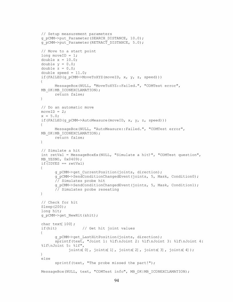
94
// Setup measurement parameters g_pCMM->put_Parameter(SEARCH_DISTANCE, 10.0); g_pCMM->put_Parameter(RETRACT_DISTANCE, 5.0); // Move to a start point long moveID = 1; double x = 10.0; double y = 0.0; double z = 0.0; double speed = 11.0; if(FAILED(g_pCMM->MoveToXYZ(moveID, x, y, z, speed))) { MessageBox(NULL, "MoveToXYZ::Failed.", "COMTest error",
MB_OK|MB_ICONEXCLAMATION); return false; } // Do an automatic move moveID = 2; x = 5.0; if(FAILED(g_pCMM->AutoMeasure(moveID, x, y, z, speed))) { MessageBox(NULL, "AutoMeasure::Failed.", "COMTest error",
MB_OK|MB_ICONEXCLAMATION); return false; } // Simulate a hit int retVal = MessageBoxEx(NULL, "Simulate a hit?", "COMTest question",
MB_YESNO, 0x0409); if(IDYES == retVal) { g_pCMM->get_CurrentPosition(joints, direction); g_pCMM->SendConditionChangedEvent(joints, 5, Mask, Condition0);
// Simulates probe hit g_pCMM->SendConditionChangedEvent(joints, 5, Mask, Condition1);
// Simulates probe reseating } // Check for hit Sleep(200); long hit; g_pCMM->get_NewHit(&hit); char text[100]; if(hit) // Get hit joint values { g_pCMM->get_LastHitPosition(joints, direction); sprintf(text, "Joint 1: %lf\nJoint 2: %lf\nJoint 3: %lf\nJoint 4:
%lf\nJoint 5: %lf", joints[0], joints[1], joints[2], joints[3], joints[4]); } else sprintf(text, "The probe missed the part!"); MessageBox(NULL, text, "COMTest info", MB_OK|MB_ICONEXCLAMATION);

95
// Put the CMM system in shutdown mode g_pCMM->put_ControlMode(MODE_SHUTDOWN); // Simulate switching the probe off g_pCMM->SendConditionChangedEvent(joints, 5, Mask, Condition0); return true; }