flexible conductors product overview product range … eriflex flexibar insulated flexible busbar...
TRANSCRIPT
Flexible ConduCtors Flexible ConduCtors overview
Spec-01138 CEQUIPMENT PROTECTIONSUBJECT TO CHANGE WITHOUT NOTICEPower and GroundinG ConneCtivity1
Spec-01138c763.422.2211763.422.2600
Power and GroundinG ConneCtivityFlexible ConduCtorsFlexible ConduCtors overview
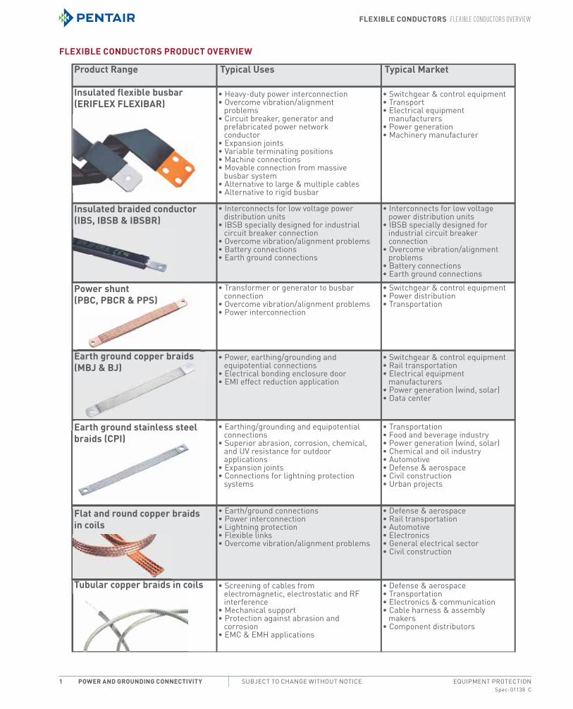
Flexible ConduCtors ProduCt overview
Product Range
Insulated flexible busbar(ERIFLEX FLEXIBAR)
Insulated braided conductor (IBS, IBSB & IBSBR)
Power shunt (PBC, PBCR & PPS)
Earth ground copper braids (MBJ & BJ)
Earth ground stainless steel braids (CPI)
Flat and round copper braidsin coils
Tubular copper braids in coils
Typical Uses
• Heavy-duty power interconnection• Overcome vibration/alignment
problems• Circuit breaker, generator and
prefabricated power network conductor
• Expansion joints• Variable terminating positions• Machine connections• Movable connection from massive
busbar system• Alternative to large & multiple cables• Alternative to rigid busbar
• Interconnects for low voltage power distribution units
• IBSB specially designed for industrial circuit breaker connection
• Overcome vibration/alignment problems• Battery connections• Earth ground connections
• Transformer or generator to busbar connection
• Overcome vibration/alignment problems• Power interconnection
• Switchgear & control equipment• Power distribution• Transportation
• Power, earthing/grounding and equipotential connections
• Electrical bonding enclosure door• EMI effect reduction application
• Switchgear & control equipment• Rail transportation• Electrical equipment
manufacturers• Power generation (wind, solar)• Data center
• Switchgear & control equipment• Transport• Electrical equipment
manufacturers• Power generation• Machinery manufacturer
• Interconnects for low voltage power distribution units
• IBSB specially designed for industrial circuit breaker connection
• Overcome vibration/alignment problems
• Battery connections• Earth ground connections
• Earthing/grounding and equipotential connections
• Superior abrasion, corrosion, chemical, and UV resistance for outdoor applications
• Expansion joints• Connections for lightning protection
systems
• Transportation • Food and beverage industry• Power generation (wind, solar)• Chemical and oil industry• Automotive• Defense & aerospace• Civil construction• Urban projects
• Earth/ground connections• Power interconnection• Lightning protection• Flexible links• Overcome vibration/alignment problems
• Defense & aerospace• Rail transportation• Automotive• Electronics• General electrical sector• Civil construction
• Screening of cables from electromagnetic, electrostatic and RF interference
• Mechanical support• Protection against abrasion and
corrosion• EMC & EMH applications
• Defense & aerospace• Transportation• Electronics & communication• Cable harness & assembly
makers• Component distributors
Typical Market
Flexible ConduCtors Flexible ConduCtors overview
Spec-01138 CPH 763.422.2211 • FAX 763.422.2600 • PentAirProtect.comEQUIPMENT PROTECTION Power and GroundinG ConneCtivity 2
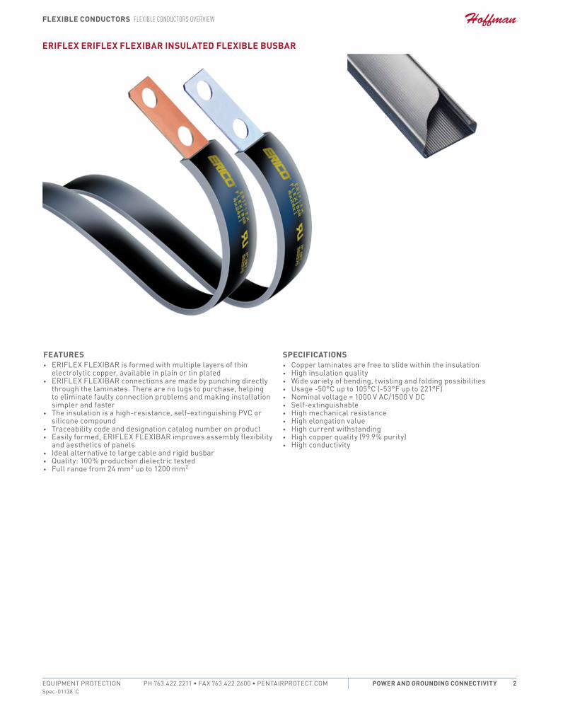
eriFlex eriFlex Flexibar insulated Flexible busbar
Features• eriFLeX FLeXiBAr is formed with multiple layers of thin
electrolytic copper, available in plain or tin plated• eriFLeX FLeXiBAr connections are made by punching directly
through the laminates. there are no lugs to purchase, helping to eliminate faulty connection problems and making installation simpler and faster
• the insulation is a high-resistance, self-extinguishing PVc or silicone compound
• traceability code and designation catalog number on product• easily formed, eriFLeX FLeXiBAr improves assembly flexibility
and aesthetics of panels• ideal alternative to large cable and rigid busbar• Quality: 100% production dielectric tested• Full range from 24 mm2 up to 1200 mm2
sPeCiFiCations• copper laminates are free to slide within the insulation• High insulation quality• Wide variety of bending, twisting and folding possibilities• Usage -50°c up to 105°c (-53°F up to 221°F) • nominal voltage = 1000 V Ac/1500 V Dc • Self-extinguishable• High mechanical resistance• High elongation value• High current withstanding• High copper quality (99.9% purity)• High conductivity
Flexible ConduCtors eriFlex FlexibAr busbArs And ACCessories
Spec-01138 CEQUIPMENT PROTECTIONSUBJECT TO CHANGE WITHOUT NOTICEPower and GroundinG ConneCtivity3
eriFlex FlexibAr busbArs And ACCessories
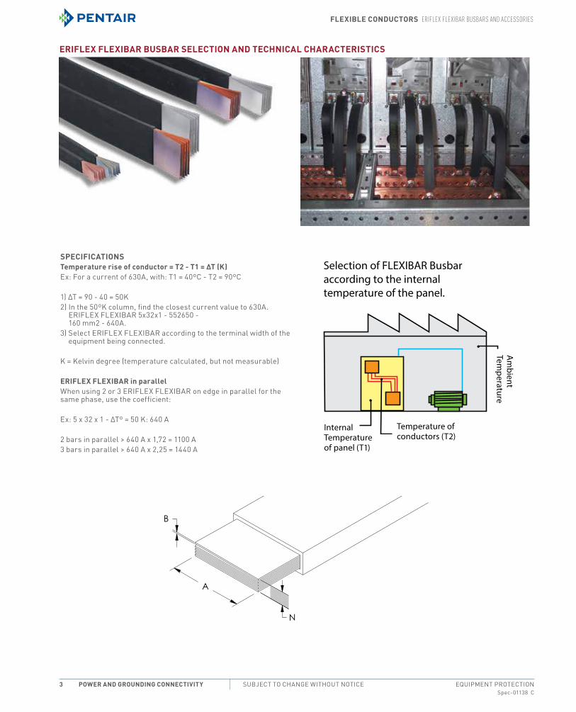
eriFlex Flexibar busbar seleCtion and teChniCal CharaCteristiCs
sPeCiFiCationstemperature rise of conductor = t2 - t1 = Δt (K)ex: For a current of 630A, with: t1 = 40ºc - t2 = 90ºc
1) ∆t = 90 - 40 = 50K2) in the 50ºK column, find the closest current value to 630A.
eriFLeX FLeXiBAr 5x32x1 - 552650 - 160 mm2 - 640A.
3) Select eriFLeX FLeXiBAr according to the terminal width of the equipment being connected.
K = Kelvin degree (temperature calculated, but not measurable)
eriFlex Flexibar in parallelWhen using 2 or 3 eriFLeX FLeXiBAr on edge in parallel for the same phase, use the coefficient:
ex: 5 x 32 x 1 - ∆tº = 50 K: 640 A
2 bars in parallel > 640 A x 1,72 = 1100 A3 bars in parallel > 640 A x 2,25 = 1440 A
Selection of FLEXIBAR Busbaraccording to the internal temperature of the panel.
Internal Temperature of panel (T1)
Temperature of conductors (T2)
Am
bient Tem
perature

Flexible ConduCtors eriFlex FlexibAr busbArs And ACCessories
Spec-01138 CPH 763.422.2211 • FAX 763.422.2600 • PentAirProtect.comEQUIPMENT PROTECTION Power and GroundinG ConneCtivity 4
typical application
Current rating
eriFlex Flexibar
CompositionΔt 20° C (a)
Δt 30° C (a)Δt 35° C (a) Δt 40° C (a)
Δt 45° C (a)Δt 50° C (a)
Δt 60° C (a)Δt 65° C (a) Δt 70° C (a)“neC
310-16 75° C”
“neC 310-16 90° C”
“neC 310-16 60° C”
125 A
3 9 0.8 101 126 138 148 158 167 185 193 2013 13 0.5 102 128 139 150 160 169 187 195 2032 15.5 0.8 121 152 166 178 190 201 222 232 2416 13 0.5 150 188 205 221 235 249 275 287 2996 9 0.8 153 192 210 226 241 255 281 293 305
250 A
2 20 1 168 211 229 247 263 279 307 321 3344 15.5 0.8 178 223 243 262 279 295 326 340 3542 24 1 195 244 266 286 305 323 357 373 3883 20 1 210 263 286 308 328 347 383 400 4166 15.5 0.8 225 282 308 331 353 374 412 430 4483 24 1 243 304 331 356 379 402 443 463 4824 20 1 246 308 336 361 385 408 450 470 4892 32 1 248 311 338 364 388 411 454 474 493
400 A
5 20 1 280 351 382 411 438 464 512 535 5564 24 1 285 356 388 418 445 472 520 543 5652 40 1 301 376 409 440 470 497 549 573 5963 32 1 308 385 419 451 481 510 562 587 6116 20 1 311 390 424 457 487 516 569 594 6185 24 1 322 403 439 472 504 534 589 615 6406 24 1 357 448 487 524 559 592 653 682 7104 32 1 359 449 489 526 561 594 655 684 7123 40 1 371 464 505 544 580 614 677 707 7365 32 1 405 507 552 594 633 671 740 773 8048 24 1 424 531 578 622 663 702 775 809 8414 40 1 432 541 589 633 675 715 789 824 8576 32 1 448 561 611 657 701 742 819 855 8893 50 1 449 562 612 658 702 743 820 856 891
10 24 1 484 606 660 710 757 802 885 924 9615 40 1 486 608 662 712 759 804 887 926 964
800 A
4 50 1 521 651 709 763 813 861 950 992 10328 32 1 525 657 715 770 821 869 959 1001 10426 40 1 535 669 728 784 835 885 976 1019 10613 63 1 549 687 747 804 857 907 1002 1046 10885 50 1 583 730 794 855 911 965 1065 1112 11576 45 1 588 736 801 862 919 973 1074 1121 1167
10 32 1 595 745 811 873 931 986 1088 1136 11828 40 1 628 786 855 920 981 1039 1146 1197 12464 63 1 633 792 861 927 988 1046 1155 1205 12556 50 1 641 802 873 940 1002 1061 1171 1222 12723 80 1 675 844 918 988 1053 1115 1231 1285 1337
10 40 1 702 879 956 1029 1097 1162 1282 1338 13935 63 1 706 883 961 1033 1102 1167 1288 1344 13998 50 1 741 927 1009 1085 1157 1226 1352 1412 1469
1200 A
6 63 1 772 966 1051 1130 1205 1276 1408 1470 15304 80 1 776 970 1056 1136 1211 1282 1415 1477 1538
10 50 1 831 1040 1132 1217 1298 1375 1517 1584 16485 80 1 861 1077 1172 1260 1344 1423 1570 1640 17068 63 1 886 1108 1205 1297 1383 1464 1616 1687 17566 80 1 938 1172 1275 1372 1463 1549 1709 1785 1858
10 63 1 985 1232 1341 1442 1538 1628 1797 1876 1953
1600 A
5 100 1 1041 1301 1416 1523 1624 1719 1898 1982 20628 80 1 1073 1341 1460 1570 1674 1773 1956 2043 21266 100 1 1132 1414 1539 1655 1765 1869 2062 2153 2241
10 80 1 1187 1484 1614 1736 1851 1960 2164 2259 23518 100 1 1279 1598 1739 1870 1994 2111 2330 2433 2532
2000 A10 100 1 1413 1765 1921 2066 2203 2332 2574 2688 279712 100 1 1537 1920 2089 2247 2396 2537 2800 2924 3043
ADMISSIBLE CURRENTS: This table indicates the temperature rise produced by chosen current in the given section. This calculation does not take into account the heat dissipation from the switch gear.∆T = Temperature of conductors – Internal temperature of panel.UL, UR, cUL, cUR, cULus and cURus are registered certification marks of UL LLC.NEC is a registered trademark of, and National Electrical Code (NEC) standard is a copyright of the National Fire Protection Association, Inc.

Flexible ConduCtors eriFlex FlexibAr busbArs And ACCessories
Spec-01138 CEQUIPMENT PROTECTIONSUBJECT TO CHANGE WITHOUT NOTICEPower and GroundinG ConneCtivity5
eriFlex Flexibar, tinned CoPPer
industry standards
certification Details: UL 67, UL 758
cSA c22.2 no. 0 and 210complies With: iec 60439.1, iec 61439.1, iec 61439.1 class ii
Features• thin layers of tinned electrolytic copper formed into a stack• insulated by high-resistance, self-extinguishing PVc with less
than 20% contact with conductor for high flexibility• easily bent, folded, and twisted, improving assembly flexibility,
shortening connections, and decreasing footprint• Dramatically smaller and more flexible than comparable cable
based on ampacity• Better power density than cable with lower skin effect ratio• connections made by punching and bolting directly through the
copper laminates, clamping onto the end of the eriFLeX• eriFLeX FLeXiBAr, or welding using cADWeLD• no lugs needed, reducing installation time and improving
resistance to vibration• Weight savings and material savings compared to wire
alternatives• reduces total installation cost• traceability codes and designation part numbers printed on
insulation• 100% production dielectric tested• UL 758 Appliance Wiring material requirements for cold Bend
testing at -40°c and -50°c (-40°F and -58°F)• GoSt compliant• roHS compliant
sPeCiFiCations• material: copper, Polyvinyl chloride• Dielectric Strength: 20 kV/mm• Flammability rating: UL 94V-0• insulation elongation: 370 %• insulation thickness: 0.08”• nominal Voltage, UL/iec: 1,000 VAc, 1,500 VDc• operating temperature: -58 to 221 °F• Forming temperature: 32 – 131 °F
Finish• Finish: tinned

Flexible ConduCtors eriFlex FlexibAr busbArs And ACCessories
Spec-01138 CPH 763.422.2211 • FAX 763.422.2600 • PentAirProtect.comEQUIPMENT PROTECTION Power and GroundinG ConneCtivity 6
typical Application current rating: 125 A
Catalog Number L (Ft.) .T 30 K (A) .T 45 K (A) .T 60 K (A) N (in.) A (in.) B (in.) Cross Section (kcmil) 2 Bar Current Coefficient 3 Bar Current Coefficient Qty.
FLEX2MTC3X9X08 6.56 126 158 185 3 0.354 0.031 42.63 1.72 2.25 1
FLEX2MTC3X13 6.56 128 160 187 3 0.512 0.02 38.48 1.72 2.25 1
FLEX2MTC2X155 6.56 152 190 222 2 0.61 0.031 48.94 1.72 2.25 1
FLEX2MTC6X13 6.56 188 235 275 6 0.512 0.02 77 1.72 2.25 1
FLEX2MTC6X9X08 6.56 192 241 281 6 0.354 0.031 85.26 1.72 2.25 1
ADMISSIBLE CURRENTS: This table indicates the temperature rise produced by chosen current in the given section. This calculation does not take into account the heat dissipation from the switch gear.
ΔT = Temperature of conductors – Internal temperature of panel.
typical Application current rating: 250 A
Catalog Number L (Ft.) .T 30 K (A) .T 45 K (A) .T 60 K (A) N (in.) A (in.) B (in.) Cross Section (kcmil) 2 Bar Current Coefficient 3 Bar Current Coefficient Qty.
FLEX2MTC4X16 6.56 223 279 326 4 0.61 0.031 97.89 1.72 2.25 1
FLEX2MTC6X16 6.56 282 353 412 6 0.61 0.031 146.83 1.72 2.25 1
FLEX3MTC2X20X1 9.84 211 263 307 2 0.787 0.039 78.94 1.72 2.25 1
FLEX3MTC2X24X1 9.84 244 305 357 2 0.945 0.039 94.73 1.72 2.25 1
FLEX3MTC3X20X1 9.84 263 328 383 3 0.787 0.039 118.41 1.72 2.25 1
FLEX3MTC3X24X1 9.84 304 379 443 3 0.945 0.039 142.1 1.72 2.25 1
FLEX3MTC4X20X1 9.84 308 385 450 4 0.787 0.039 157.88 1.72 2.25 1
FLEX3MTC2X32X1 9.84 311 385 454 2 1.26 0.039 126.3 1.72 2.25 1
ADMISSIBLE CURRENTS: This table indicates the temperature rise produced by chosen current in the given section. This calculation does not take into account the heat dissipation from the switch gear.
ΔT = Temperature of conductors – Internal temperature of panel.
typical Application current rating: 400 A
Catalog Number L (Ft.) .T 30 K (A) .T 45 K (A) .T 60 K (A) N (in.) A (in.) B (in.) Cross Section (kcmil) 2 Bar Current Coefficient 3 Bar Current Coefficient Qty.
FLEX3MTC5X20X1 9.84 351 438 512 5 0.787 0.039 197.35 1.72 2.25 1
FLEX3MTC4X24X1 9.84 356 445 520 4 0.945 0.039 189.46 1.72 2.25 1
FLEX3MTC2X40X1 9.84 376 470 549 2 1.575 0.039 157.88 1.72 2.25 1
FLEX3MTC3X32X1 9.84 385 481 562 3 1.26 0.039 189.46 1.72 2.25 1
FLEX3MTC6X20X1 9.84 390 487 569 6 0.787 0.039 236.8 1.72 2.25 1
FLEX3MTC5X24X1 9.84 403 504 589 5 0.945 0.039 236.8 1.72 2.25 1
FLEX3MTC6X24X1 9.84 448 559 653 6 0.945 0.039 284.19 1.72 2.25 1
FLEX3MTC4X32X1 9.84 449 561 665 4 1.26 0.039 252.6 1.72 2.25 1
FLEX3MTC3X40X1 9.84 464 580 677 3 1.575 0.039 236.8 1.72 2.25 1
FLEX3MTC5X32X1 9.84 507 633 740 5 1.26 0.039 315.7 1.72 2.25 1
FLEX3MTC8X24X1 9.84 531 663 775 8 0.945 0.039 378.9 1.72 2.25 1
FLEX3MTC4X40X1 9.84 541 675 789 4 1.575 0.039 315.7 1.72 2.25 1
FLEX3MTC6X32X1 9.84 561 701 819 6 1.26 0.039 378.9 1.72 2.25 1
FLEX3MTC3X50X1 9.84 562 702 820 3 1.969 0.039 296.03 1.72 2.25 1
FLEX3MTC10X24X1 9.84 606 757 885 10 0.945 0.039 473.65 1.72 2.25 1
FLEX3MTC5X40X1 9.84 608 759 887 5 1.575 0.039 394.7 1.72 2.25 1
ADMISSIBLE CURRENTS: This table indicates the temperature rise produced by chosen current in the given section. This calculation does not take into account the heat dissipation from the switch gear.
ΔT = Temperature of conductors – Internal temperature of panel.
Flexible ConduCtors eriFlex FlexibAr busbArs And ACCessories
Spec-01138 CEQUIPMENT PROTECTIONSUBJECT TO CHANGE WITHOUT NOTICEPower and GroundinG ConneCtivity7
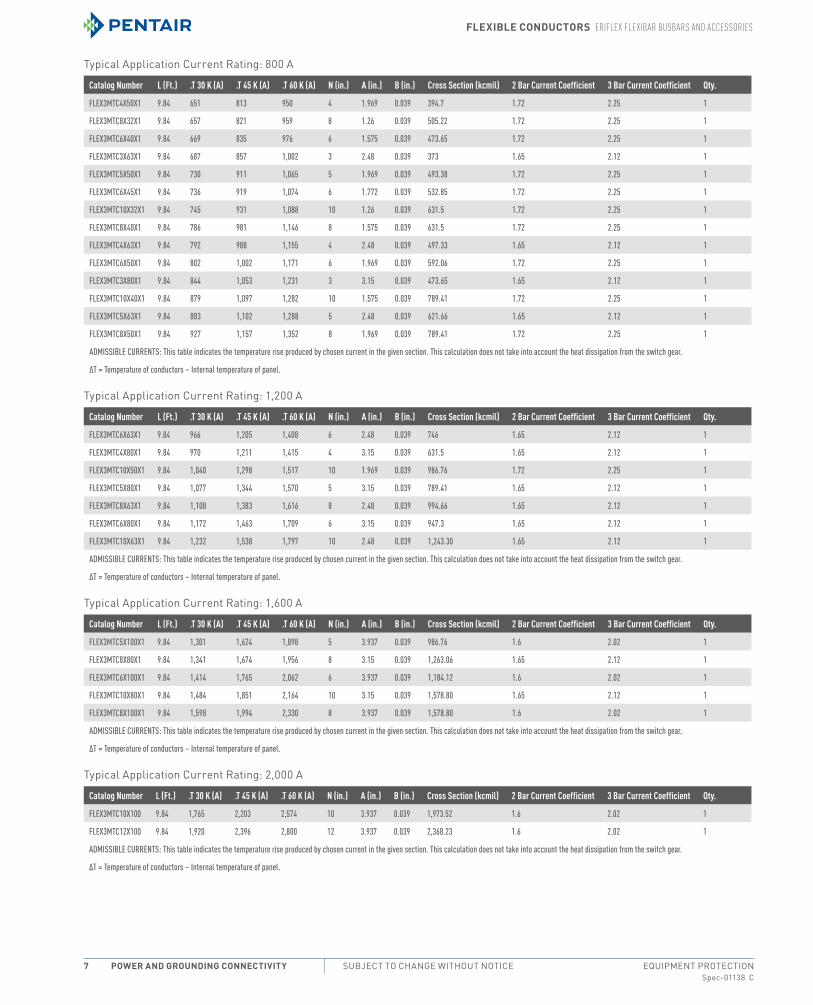
typical Application current rating: 800 A
Catalog Number L (Ft.) .T 30 K (A) .T 45 K (A) .T 60 K (A) N (in.) A (in.) B (in.) Cross Section (kcmil) 2 Bar Current Coefficient 3 Bar Current Coefficient Qty.
FLEX3MTC4X50X1 9.84 651 813 950 4 1.969 0.039 394.7 1.72 2.25 1
FLEX3MTC8X32X1 9.84 657 821 959 8 1.26 0.039 505.22 1.72 2.25 1
FLEX3MTC6X40X1 9.84 669 835 976 6 1.575 0.039 473.65 1.72 2.25 1
FLEX3MTC3X63X1 9.84 687 857 1,002 3 2.48 0.039 373 1.65 2.12 1
FLEX3MTC5X50X1 9.84 730 911 1,065 5 1.969 0.039 493.38 1.72 2.25 1
FLEX3MTC6X45X1 9.84 736 919 1,074 6 1.772 0.039 532.85 1.72 2.25 1
FLEX3MTC10X32X1 9.84 745 931 1,088 10 1.26 0.039 631.5 1.72 2.25 1
FLEX3MTC8X40X1 9.84 786 981 1,146 8 1.575 0.039 631.5 1.72 2.25 1
FLEX3MTC4X63X1 9.84 792 988 1,155 4 2.48 0.039 497.33 1.65 2.12 1
FLEX3MTC6X50X1 9.84 802 1,002 1,171 6 1.969 0.039 592.06 1.72 2.25 1
FLEX3MTC3X80X1 9.84 844 1,053 1,231 3 3.15 0.039 473.65 1.65 2.12 1
FLEX3MTC10X40X1 9.84 879 1,097 1,282 10 1.575 0.039 789.41 1.72 2.25 1
FLEX3MTC5X63X1 9.84 883 1,102 1,288 5 2.48 0.039 621.66 1.65 2.12 1
FLEX3MTC8X50X1 9.84 927 1,157 1,352 8 1.969 0.039 789.41 1.72 2.25 1
ADMISSIBLE CURRENTS: This table indicates the temperature rise produced by chosen current in the given section. This calculation does not take into account the heat dissipation from the switch gear.
ΔT = Temperature of conductors – Internal temperature of panel.
typical Application current rating: 1,200 A
Catalog Number L (Ft.) .T 30 K (A) .T 45 K (A) .T 60 K (A) N (in.) A (in.) B (in.) Cross Section (kcmil) 2 Bar Current Coefficient 3 Bar Current Coefficient Qty.
FLEX3MTC6X63X1 9.84 966 1,205 1,408 6 2.48 0.039 746 1.65 2.12 1
FLEX3MTC4X80X1 9.84 970 1,211 1,415 4 3.15 0.039 631.5 1.65 2.12 1
FLEX3MTC10X50X1 9.84 1,040 1,298 1,517 10 1.969 0.039 986.76 1.72 2.25 1
FLEX3MTC5X80X1 9.84 1,077 1,344 1,570 5 3.15 0.039 789.41 1.65 2.12 1
FLEX3MTC8X63X1 9.84 1,108 1,383 1,616 8 2.48 0.039 994.66 1.65 2.12 1
FLEX3MTC6X80X1 9.84 1,172 1,463 1,709 6 3.15 0.039 947.3 1.65 2.12 1
FLEX3MTC10X63X1 9.84 1,232 1,538 1,797 10 2.48 0.039 1,243.30 1.65 2.12 1
ADMISSIBLE CURRENTS: This table indicates the temperature rise produced by chosen current in the given section. This calculation does not take into account the heat dissipation from the switch gear.
ΔT = Temperature of conductors – Internal temperature of panel.
typical Application current rating: 1,600 A
Catalog Number L (Ft.) .T 30 K (A) .T 45 K (A) .T 60 K (A) N (in.) A (in.) B (in.) Cross Section (kcmil) 2 Bar Current Coefficient 3 Bar Current Coefficient Qty.
FLEX3MTC5X100X1 9.84 1,301 1,624 1,898 5 3.937 0.039 986.76 1.6 2.02 1
FLEX3MTC8X80X1 9.84 1,341 1,674 1,956 8 3.15 0.039 1,263.06 1.65 2.12 1
FLEX3MTC6X100X1 9.84 1,414 1,765 2,062 6 3.937 0.039 1,184.12 1.6 2.02 1
FLEX3MTC10X80X1 9.84 1,484 1,851 2,164 10 3.15 0.039 1,578.80 1.65 2.12 1
FLEX3MTC8X100X1 9.84 1,598 1,994 2,330 8 3.937 0.039 1,578.80 1.6 2.02 1
ADMISSIBLE CURRENTS: This table indicates the temperature rise produced by chosen current in the given section. This calculation does not take into account the heat dissipation from the switch gear.
ΔT = Temperature of conductors – Internal temperature of panel.
typical Application current rating: 2,000 A
Catalog Number L (Ft.) .T 30 K (A) .T 45 K (A) .T 60 K (A) N (in.) A (in.) B (in.) Cross Section (kcmil) 2 Bar Current Coefficient 3 Bar Current Coefficient Qty.
FLEX3MTC10X100 9.84 1,765 2,203 2,574 10 3.937 0.039 1,973.52 1.6 2.02 1
FLEX3MTC12X100 9.84 1,920 2,396 2,800 12 3.937 0.039 2,368.23 1.6 2.02 1
ADMISSIBLE CURRENTS: This table indicates the temperature rise produced by chosen current in the given section. This calculation does not take into account the heat dissipation from the switch gear.
ΔT = Temperature of conductors – Internal temperature of panel.

Flexible ConduCtors eriFlex FlexibAr busbArs And ACCessories
Spec-01138 CPH 763.422.2211 • FAX 763.422.2600 • PentAirProtect.comEQUIPMENT PROTECTION Power and GroundinG ConneCtivity 8
eriFlex eriFlex Flexibar end Cover
• end cover for eriFLeX FLeXiBAr and insulated Power Braid• Allows for visual inspection of connection• easy fitting after fixing• roHS compliant• material: Polycarbonate• Flammability rating: UL 94V-0
Catalog Number Conductor Width (in.) Unit Weight (lb.) Qty.ENDCOV20 0.79 0.42 12ENDCOV24 0.94 0.48 12ENDCOV32 1.26 0.57 12
Flexible sPaCer ClamPsFeatures• easy to install• Provides support• Allows for proper cooling
uFs eriFlex Flexibar and ibsb suPPort Kit • Kit includes one rail and 24 retaining blocks• create up to three 650 mm (25.6”) supports capable of holding
four eriFLeX FLeXiBAr• retaining blocks are halogen free• roHS compliant
Catalog Number Conductor Thickness (in.)
Conductor Width (in.)
Height H (in.)
Length L (Ft.)
Width W (in.) A (in.) B (in.) Unit Weight (lb.) Qty.
UFSKIT 0.08 – 0.39 0.61 – 4.72 2.27 6.56 1.18 0.95 0.59 5.07 1
Flexible ConduCtors eriFlex FlexibAr busbArs And ACCessories
Spec-01138 CEQUIPMENT PROTECTIONSUBJECT TO CHANGE WITHOUT NOTICEPower and GroundinG ConneCtivity9
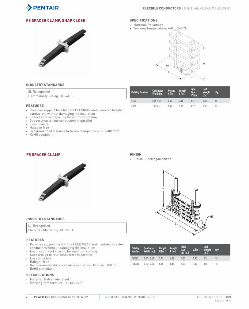
Fs sPaCer ClamP, snaP Close
industry standards
UL recognizedFlammability rating: UL 94HB
Features• Provides support for eriFLeX FLeXiBAr and insulated braided
conductors without damaging the insulation• ensures correct spacing for optimum cooling• Supports up to four conductors in parallel• easy to install• Halogen free• recommended distance between clamps: 15.75 in. (400 mm)• roHS compliant
sPeCiFiCations• material: Polyamide• Working temperature: -40 to 266 °F
Catalog Number ConductorWidth (in.)
HeightH (in.)
LengthL (in.)
HoleSizeHS (in.)
UnitWeight(lb.)
Qty.
FS24 0.95 Max 2.04 1.18 0.27 0.03 25
FS32 1.25 Max 2.04 1.49 0.27 0.04 25
Fs sPaCer ClamP
industry standards
UL recognizedFlammability rating: UL 94HB
Features• Provides support for eriFLeX FLeXiBAr and insulated braided
conductors without damaging the insulation• ensures correct spacing for optimum cooling• Supports up to four conductors in parallel• easy to install• Halogen free• recommended distance between clamps: 15.75 in. (400 mm)• roHS compliant
sPeCiFiCations• material: Polyamide, Steel• Working temperature: -40 to 266 °F
Finish• Finish: electrogalvanized
CatalogNumber
ConductorWidth (in.)
Height H (in.)
Length L (in.)
HoleSize HS (in.)
A (in.)UnitWeight(lb.)
Qty.
FS4063 1.57 – 2.48 3.74 6.54 0.33 5.90 0.22 10
FS80100 3.15 – 3.94 5.51 8.82 0.33 7.87 0.55 10

Flexible ConduCtors eriFlex FlexibAr busbArs And ACCessories
Spec-01138 CPH 763.422.2211 • FAX 763.422.2600 • PentAirProtect.comEQUIPMENT PROTECTION Power and GroundinG ConneCtivity 10
rFs reinForCed eriFlex Flexibar suPPort
• Supports up to eight conductors in parallel• ensures correct spacing for optimum cooling• easy to install• Spacers are halogen free• roHS compliant
Catalog Number Conductor Width (in.) D (in.) H (in.) W (in.) HS (in.) TS A (in.) B (in.) C (in.) Unit Weight (lb.) Qty.
RFS4063 1.57 – 2.48 1.57 8.26 6.89 0.35 M8 5.9 4.72 3.54 0.53 1
RFS80100 3.15 – 3.94 1.57 8.26 8.86 0.35 M8 7.87 6.69 5.51 0.66 1
Flexible ConduCtors insulAted brAided ConduCtors
Spec-01138 CEQUIPMENT PROTECTIONSUBJECT TO CHANGE WITHOUT NOTICEPower and GroundinG ConneCtivity11
insulAted brAided ConduCtors
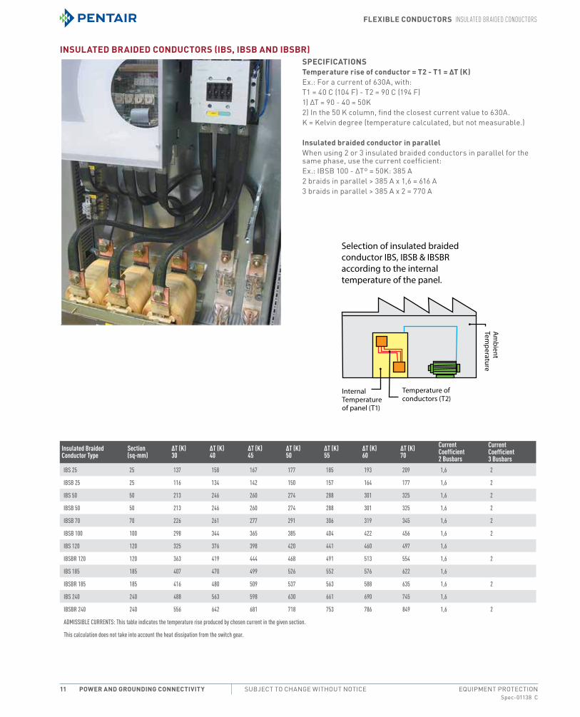
insulated braided ConduCtors (ibs, ibsb and ibsbr)sPeCiFiCationstemperature rise of conductor = t2 - t1 = Δt (K)ex.: For a current of 630A, with:t1 = 40 c (104 F) - t2 = 90 c (194 F)1) Δt = 90 - 40 = 50K2) in the 50 K column, find the closest current value to 630A.K = Kelvin degree (temperature calculated, but not measurable.)
insulated braided conductor in parallelWhen using 2 or 3 insulated braided conductors in parallel for the same phase, use the current coefficient:ex.: iBSB 100 - Δtº = 50K: 385 A2 braids in parallel > 385 A x 1,6 = 616 A3 braids in parallel > 385 A x 2 = 770 A
Selection of insulated braided conductor IBS, IBSB & IBSBR according to the internal temperature of the panel.
Internal Temperature of panel (T1)
Temperature of conductors (T2)
Am
bient Tem
perature
Insulated BraidedConductor Type
Section(sq-mm)
ΔT (K)30
ΔT (K)40
ΔT (K)45
ΔT (K)50
ΔT (K)55
ΔT (K)60
ΔT (K)70
CurrentCoefficient2 Busbars
CurrentCoefficient3 Busbars
IBS 25 25 137 158 167 177 185 193 209 1,6 2
IBSB 25 25 116 134 142 150 157 164 177 1,6 2
IBS 50 50 213 246 260 274 288 301 325 1,6 2
IBSB 50 50 213 246 260 274 288 301 325 1,6 2
IBSB 70 70 226 261 277 291 306 319 345 1,6 2
IBSB 100 100 298 344 365 385 404 422 456 1,6 2
IBS 120 120 325 376 398 420 441 460 497 1,6
IBSBR 120 120 363 419 444 468 491 513 554 1,6 2
IBS 185 185 407 470 499 526 552 576 622 1,6
IBSBR 185 185 416 480 509 537 563 588 635 1,6 2
IBS 240 240 488 563 598 630 661 690 745 1,6
IBSBR 240 240 556 642 681 718 753 786 849 1,6 2
ADMISSIBLE CURRENTS: This table indicates the temperature rise produced by chosen current in the given section.
This calculation does not take into account the heat dissipation from the switch gear.
Flexible ConduCtors insulAted brAided ConduCtors
Spec-01138 CPH 763.422.2211 • FAX 763.422.2600 • PentAirProtect.comEQUIPMENT PROTECTION Power and GroundinG ConneCtivity 12
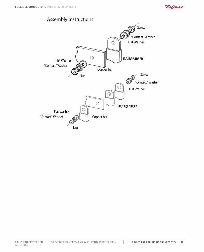
Flat Washer“Contact” Washer
Nut
Screw
“Contact” WasherFlat Washer
IBS/IBSB/IBSBR
Copper bar
Flat Washer“Contact” Washer
Nut
Screw
“Contact” Washer
Flat Washer
IBS/IBSB/IBSBR
Copper bar
Assembly Instructions
Flexible ConduCtors insulAted brAided ConduCtors
Spec-01138 CEQUIPMENT PROTECTIONSUBJECT TO CHANGE WITHOUT NOTICEPower and GroundinG ConneCtivity13
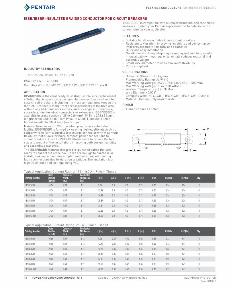
ibsb/ibsbr insulated braided ConduCtor For CirCuit breaKers
industry standards
certification Details: UL 67, UL 758
cSA c22.2 no. 0 and 210complies With: iec 60439.1, iec 61439.1, iec 61439.1 class ii
aPPliCationiBSB/iBSBr is the ideal ready-to-install flexible wire replacement solution that is specifically designed for connections to all molded case circuit breakers, including the most compact breakers on the market. it connects to the front access terminals of the breakers without any additional accessories, such as angular connectors, spreaders, ring terminal connectors or extenders. iBSB/iBSBr is available in cross section of 25 to 240 mm² (49.34 to 273.65 kcmil), lengths from 230 to 1,030 mm (9.06” to 40.55”), and 80 to 350 A tinned and 400 to 630 A bare (red) copper.manufactured in an iSo 9001 certified proprietary automated facility, iBSB/iBSBr is formed by weaving high-quality electrolytic copper wire to form a durable low voltage connector with maximum flexibility that allows for more compact power connections to circuit breakers. the iBSB/iBSBr allows users to reduce the total size and weight of the installation, improving both design flexibility and assembly aesthetics.the iBSB/iBSBr features integral pre-punched palms that are ready to connect out of the box. there are no lugs to purchase or install, making connections simpler and faster and eliminating faulty connections due to vibration or fatigue. the insulation is a high-resistance self-extinguishing PVc.
iBSB/iBSBr is compatible with all major brand molded case circuit breakers. contact your Pentair representative to determine the correct size for your application.
Features• Suitable for all main molded case circuit breakers• resistant to vibration, improving reliability and performance• improves assembly flexibility and aesthetics• Quick and easy installation• no additional cutting, stripping, crimping and punching needed• integral palm without lugs or terminals reduces material and
assembly weight• Small wire diameter provides maximum flexibility• roHS compliant
sPeCiFiCations• Dielectric Strength: 20 kV/mm• Flammability rating: UL 94V-0• max Working Voltage, iec/UL 758: 1,000 VAc, 1,500 VDc• max Working Voltage, UL 67: 600 VAc/Dc• Working temperature: 221 °F max• Wire Diameter: 0.006”• complies With: iec 60439.1, iec 61439.1, iec 61439.1 class ii• material: copper, Polyvinylchloride
Finish• tinned or bare as noted
typical Application current rating: 125 – 160 A – Finish: tinned
Catalog NumberCrossSection(kcmil)
ConductorWidth(in.)
ConductorThickness(in.)
L (in.) A (in.) B (in.) C (in.) D (in.) HS1 (in.) HS2 (in.) Qty.
IBSB25230 49.34 0.47 0.11 9.06 0.3 0.3 0.71 0.35 0.26 0.26 10
IBSB25330 49.34 0.47 0.11 12.99 0.3 0.3 0.71 0.35 0.26 0.26 10
IBSB25430 49.34 0.47 0.11 16.93 0.3 0.3 0.71 0.35 0.26 0.26 10
IBSB25530 49.34 0.47 0.11 20.87 0.3 0.3 0.71 0.35 0.26 0.26 10
IBSB25630 49.34 0.47 0.11 24.8 0.3 0.3 0.71 0.35 0.26 0.26 10
IBSB25830 49.34 0.47 0.11 32.68 0.3 0.3 0.71 0.35 0.26 0.26 10
IBSB251030 49.34 0.47 0.11 40.55 0.3 0.3 0.71 0.35 0.26 0.26 10
typical Application current rating: 250 A – Finish: tinned
Catalog NumberCrossSection(kcmil)
ConductorWidth(in.)
ConductorThickness(in.)
L (in.) A (in.) B (in.) C (in.) D (in.) HS1 (in.) HS2 (in.) Qty.
IBSB50230 98.68 0.79 0.12 9.06 0.35 0.43 1.06 0.35 0.33 0.41 10
IBSB50330 98.68 0.79 0.12 12.99 0.35 0.43 1.06 0.35 0.33 0.41 10
IBSB50430 98.68 0.79 0.12 16.93 0.35 0.43 1.06 0.35 0.33 0.41 10
IBSB50530 98.68 0.79 0.12 20.87 0.35 0.43 1.06 0.35 0.33 0.41 10
IBSB50630 98.68 0.79 0.12 24.8 0.35 0.43 1.06 0.35 0.33 0.41 10
IBSB50830 98.68 0.79 0.12 32.68 0.35 0.43 1.06 0.35 0.33 0.41 10
IBSB501030 98.68 0.79 0.12 40.55 0.35 0.43 1.06 0.35 0.33 0.41 10
Flexible ConduCtors insulAted brAided ConduCtors
Spec-01138 CPH 763.422.2211 • FAX 763.422.2600 • PentAirProtect.comEQUIPMENT PROTECTION Power and GroundinG ConneCtivity 14
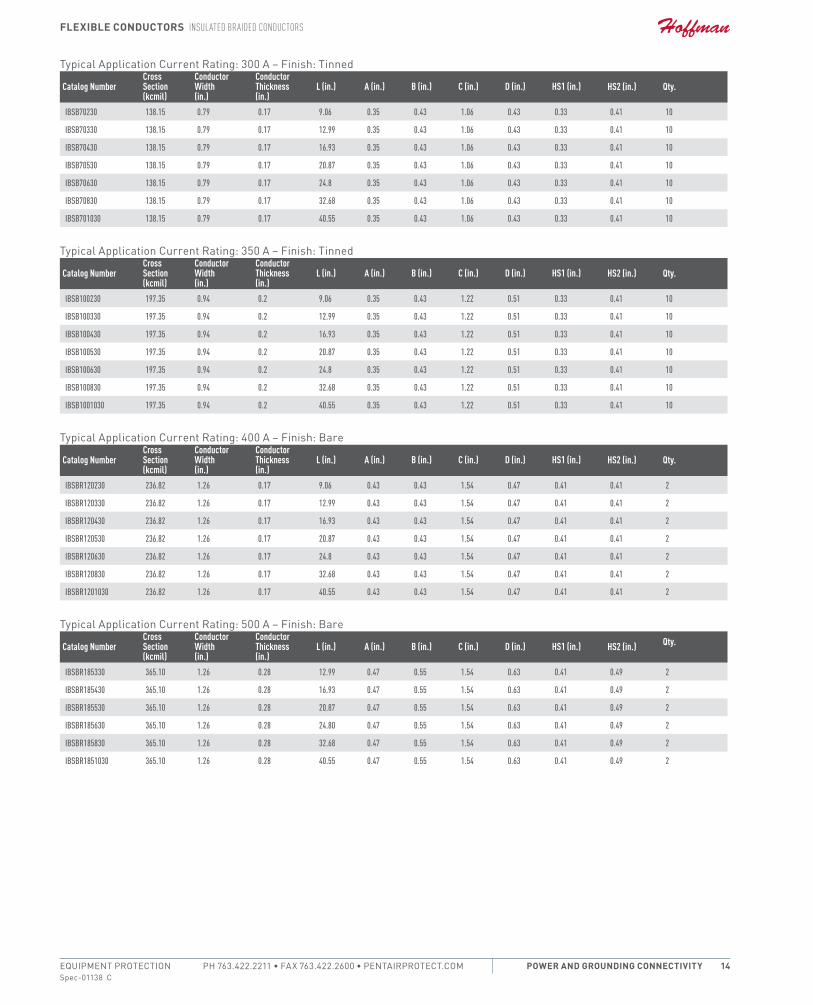
typical Application current rating: 300 A – Finish: tinned
Catalog NumberCrossSection(kcmil)
ConductorWidth(in.)
ConductorThickness(in.)
L (in.) A (in.) B (in.) C (in.) D (in.) HS1 (in.) HS2 (in.) Qty.
IBSB70230 138.15 0.79 0.17 9.06 0.35 0.43 1.06 0.43 0.33 0.41 10
IBSB70330 138.15 0.79 0.17 12.99 0.35 0.43 1.06 0.43 0.33 0.41 10
IBSB70430 138.15 0.79 0.17 16.93 0.35 0.43 1.06 0.43 0.33 0.41 10
IBSB70530 138.15 0.79 0.17 20.87 0.35 0.43 1.06 0.43 0.33 0.41 10
IBSB70630 138.15 0.79 0.17 24.8 0.35 0.43 1.06 0.43 0.33 0.41 10
IBSB70830 138.15 0.79 0.17 32.68 0.35 0.43 1.06 0.43 0.33 0.41 10
IBSB701030 138.15 0.79 0.17 40.55 0.35 0.43 1.06 0.43 0.33 0.41 10
typical Application current rating: 350 A – Finish: tinned
Catalog NumberCrossSection(kcmil)
ConductorWidth(in.)
ConductorThickness(in.)
L (in.) A (in.) B (in.) C (in.) D (in.) HS1 (in.) HS2 (in.) Qty.
IBSB100230 197.35 0.94 0.2 9.06 0.35 0.43 1.22 0.51 0.33 0.41 10
IBSB100330 197.35 0.94 0.2 12.99 0.35 0.43 1.22 0.51 0.33 0.41 10
IBSB100430 197.35 0.94 0.2 16.93 0.35 0.43 1.22 0.51 0.33 0.41 10
IBSB100530 197.35 0.94 0.2 20.87 0.35 0.43 1.22 0.51 0.33 0.41 10
IBSB100630 197.35 0.94 0.2 24.8 0.35 0.43 1.22 0.51 0.33 0.41 10
IBSB100830 197.35 0.94 0.2 32.68 0.35 0.43 1.22 0.51 0.33 0.41 10
IBSB1001030 197.35 0.94 0.2 40.55 0.35 0.43 1.22 0.51 0.33 0.41 10
typical Application current rating: 400 A – Finish: Bare
Catalog NumberCrossSection(kcmil)
ConductorWidth(in.)
ConductorThickness(in.)
L (in.) A (in.) B (in.) C (in.) D (in.) HS1 (in.) HS2 (in.) Qty.
IBSBR120230 236.82 1.26 0.17 9.06 0.43 0.43 1.54 0.47 0.41 0.41 2
IBSBR120330 236.82 1.26 0.17 12.99 0.43 0.43 1.54 0.47 0.41 0.41 2
IBSBR120430 236.82 1.26 0.17 16.93 0.43 0.43 1.54 0.47 0.41 0.41 2
IBSBR120530 236.82 1.26 0.17 20.87 0.43 0.43 1.54 0.47 0.41 0.41 2
IBSBR120630 236.82 1.26 0.17 24.8 0.43 0.43 1.54 0.47 0.41 0.41 2
IBSBR120830 236.82 1.26 0.17 32.68 0.43 0.43 1.54 0.47 0.41 0.41 2
IBSBR1201030 236.82 1.26 0.17 40.55 0.43 0.43 1.54 0.47 0.41 0.41 2
typical Application current rating: 500 A – Finish: Bare
Catalog NumberCrossSection(kcmil)
ConductorWidth(in.)
ConductorThickness(in.)
L (in.) A (in.) B (in.) C (in.) D (in.) HS1 (in.) HS2 (in.) Qty.
IBSBR185330 365.10 1.26 0.28 12.99 0.47 0.55 1.54 0.63 0.41 0.49 2
IBSBR185430 365.10 1.26 0.28 16.93 0.47 0.55 1.54 0.63 0.41 0.49 2
IBSBR185530 365.10 1.26 0.28 20.87 0.47 0.55 1.54 0.63 0.41 0.49 2
IBSBR185630 365.10 1.26 0.28 24.80 0.47 0.55 1.54 0.63 0.41 0.49 2
IBSBR185830 365.10 1.26 0.28 32.68 0.47 0.55 1.54 0.63 0.41 0.49 2
IBSBR1851030 365.10 1.26 0.28 40.55 0.47 0.55 1.54 0.63 0.41 0.49 2
Flexible ConduCtors insulAted brAided ConduCtors
Spec-01138 CEQUIPMENT PROTECTIONSUBJECT TO CHANGE WITHOUT NOTICEPower and GroundinG ConneCtivity15
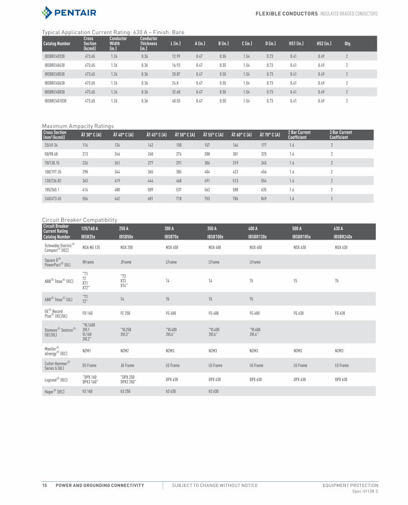
typical Application current rating: 630 A – Finish: Bare
Catalog NumberCrossSection(kcmil)
ConductorWidth(in.)
ConductorThickness(in.)
L (in.) A (in.) B (in.) C (in.) D (in.) HS1 (in.) HS2 (in.) Qty.
IBSBR240330 473.65 1.26 0.36 12.99 0.47 0.55 1.54 0.73 0.41 0.49 2
IBSBR240430 473.65 1.26 0.36 16.93 0.47 0.55 1.54 0.73 0.41 0.49 2
IBSBR240530 473.65 1.26 0.36 20.87 0.47 0.55 1.54 0.73 0.41 0.49 2
IBSBR240630 473.65 1.26 0.36 24.8 0.47 0.55 1.54 0.73 0.41 0.49 2
IBSBR240830 473.65 1.26 0.36 32.68 0.47 0.55 1.54 0.73 0.41 0.49 2
IBSBR2401030 473.65 1.26 0.36 40.55 0.47 0.55 1.54 0.73 0.41 0.49 2
maximum Ampacity ratingsCross Section (mm²/kcmil) ÄT 30° C (A) ÄT 40° C (A) ÄT 45° C (A) ÄT 50° C (A) ÄT 55° C (A) ÄT 60° C (A) ÄT 70° C (A) 2 Bar Current
Coefficient3 Bar Current Coefficient
25/49.34 116 134 142 150 157 164 177 1.6 2
50/98.68 213 246 260 274 288 301 325 1.6 2
70/138.15 226 261 277 291 306 319 345 1.6 2
100/197.35 298 344 365 385 404 422 456 1.6 2
120/236.82 363 419 444 468 491 513 554 1.6 2
185/365.1 416 480 509 537 563 588 635 1.6 2
240/473.65 556 642 681 718 753 786 849 1.6 2
circuit Breaker compatibilityCircuit Breaker Current Rating 125/160 A 250 A 300 A 350 A 400 A 500 A 630 ACatalog Number IBSB25x IBSB50x IBSB70x IBSB100x IBSBR120x IBSBR185x IBSBR240x
Schneider Electric® Compact® (IEC) NSA NG 125 NSX 250 NSX 400 NSX 400 NSX 400 NSX 630 NSX 630
Square D® PowerPact® (UL) HFrame JFrame LFrame LFrame LFrame
ABB® Tmax® (IEC)"T1 T2 XT1 XT2"
"T3 XT3 XT4"
T4 T4 T5 T5 T5
ABB® Tmax® (UL) "T1 T2" T4 T5 T5 T5
GE® Record Plus® (IEC/UL) FD 160 FE 250 FG 400 FG 400 FG 400 FG 630 FG 630
Siemens® Sentron® (IEC/UL)
"VL160X 3VL1 VL160 3VL2"
"VL250 3VL3"
"VL400 3VL4"
"VL400 3VL4"
"VL400 3VL4"
Moeller® xEnergy® (IEC) NZM1 NZM2 NZM3 NZM3 NZM3 NZM3 NZM3
Cutler Hammer® Series G (UL) EG Frame JG Frame LG Frame LG Frame LG Frame LG Frame LG Frame
Legrand® (IEC) "DPX 160 DPX3 160"
"DPX 250 DPX3 250" DPX 630 DPX 630 DPX 630 DPX 630 DPX 630
Hager® (IEC) h3 160 h3 250 h3 630 h3 630

Flexible ConduCtors insulAted brAided ConduCtors
Spec-01138 CPH 763.422.2211 • FAX 763.422.2600 • PentAirProtect.comEQUIPMENT PROTECTION Power and GroundinG ConneCtivity 16
ibs Flat insulated braided ConduCtor
industry standards
certification Details: UL 67, UL 758
cSA c22.2 no. 0 and 210complies With: iec 60439.1, iec 61439.1, iec 61439.1 class ii
aPPliCationiBS Flat insulated Braided conductors are the ideal ready-to-install flexible wire replacement solution. they connect directly to the front access terminals of an electrical device without the need for additional accessories, such as angular connectors, spreaders, ring terminal connectors or extenders. iBS Flat insulated Braided conductors are available in cross section of 25 and 50 mm² (49.34 and 98.68 kcmil), lengths from 230 to 1,030 mm (9.06” to 40.55”), and amperages ranging from 177 to 274 A.manufactured in an iSo 9001 certified proprietary automated facility, iBS Flat insulated Braided conductors are formed by weaving high-quality electrolytic copper wire to form a durable low voltage connector with maximum flexibility that allows for more compact power to electrical device. the iBS Flat insulated Braided conductor allows users to reduce the total size and weight of the installation, improving both design flexibility and assembly aesthetics.the iBS Flat insulated Braided conductor features integral pre-punched palms that are ready to connect out of the box. there are no lugs to purchase or install, making connections simpler and faster and eliminating faulty connections due to vibration or fatigue. the insulation is a high-resistance self-extinguishing PVc.
Features• Suitable for all main electrical devices• resistant to vibration, improving reliability and performance• improves assembly flexibility and aesthetics• Quick and easy installation• no additional cutting, stripping, crimping and punching needed• integral palm without lugs or terminals reduces material and
assembly weight• Small wire diameter provides maximum flexibility• roHS compliant
sPeCiFiCations• Dielectric Strength: 20 kV/mm• Flammability rating: UL 94V-0• max Working Voltage, iec/UL 758: 1,000 VAc, 1,500 VDc• max Working Voltage, UL 67: 600 VAc/Dc• Working temperature: 221 °F max• Wire Diameter: 0.006 (in.)• material: copper, Polyvinylchloride
Finish• Finish: tinned
typical Application current rating: 160 A
Catalog NumberCrossSection(kcmil)
ConductorWidth(in.)
ConductorThickness(in.)
L (in.) A (in.) B (in.) C (in.) D (in.) HS1 (in.) HS2 (in.) Qty.
IBS25230810 49.34 0.79 0.07 9.06 0.39 0.47 0.98 0.24 0.33 0.41 10
IBS25330810 49.34 0.79 0.07 12.99 0.39 0.47 0.98 0.24 0.33 0.41 10
IBS25430810 49.34 0.79 0.07 16.93 0.39 0.47 0.98 0.24 0.33 0.41 10
IBS25530810 49.34 0.79 0.07 20.87 0.39 0.47 0.98 0.24 0.33 0.41 10
IBS25630810 49.34 0.79 0.07 24.8 0.39 0.47 0.98 0.24 0.33 0.41 10
IBS25830810 49.34 0.79 0.07 32.68 0.39 0.47 0.98 0.24 0.33 0.41 10
IBS251030810 49.34 0.79 0.07 40.55 0.39 0.47 0.98 0.24 0.33 0.41 10
typical Application current rating: 250 A
Catalog NumberCrossSection(kcmil)
ConductorWidth(in.)
ConductorThickness(in.)
L (in.) A (in.) B (in.) C (in.) D (in.) HS1 (in.) HS2 (in.) Qty.
IBS5023010 98.68 0.79 0.15 9.06 0.47 0.47 0.98 0.3 0.41 0.41 10
IBS5033010 98.68 0.79 0.15 12.99 0.47 0.47 0.98 0.3 0.41 0.41 10
IBS5043010 98.68 0.79 0.15 16.93 0.47 0.47 0.98 0.3 0.41 0.41 10
IBS5053010 98.68 0.79 0.15 20.87 0.47 0.47 0.98 0.3 0.41 0.41 10
IBS5063010 98.68 0.79 0.15 24.8 0.47 0.47 0.98 0.3 0.41 0.41 10
IBS5083010 98.68 0.79 0.15 32.68 0.47 0.47 0.98 0.3 0.41 0.41 10
IBS50103010 98.68 0.79 0.15 40.55 0.47 0.47 0.98 0.3 0.41 0.41 10

Flexible ConduCtors insulAted brAided ConduCtors
Spec-01138 CEQUIPMENT PROTECTIONSUBJECT TO CHANGE WITHOUT NOTICEPower and GroundinG ConneCtivity17
maximum Ampacity ratingsCross Section (mm²/kcmil) ÄT 30° C (A) ÄT 40° C (A) ÄT 45° C (A) ÄT 50° C (A) ÄT 55° C (A) ÄT 60° C (A) ÄT 70° C (A) 2 Bar Current
Coefficient3 Bar Current Coefficient
25/49.34 137 158 167 177 185 193 209 1.6 2
50/98.68 213 246 260 274 288 301 325 1.6 2
circuit Breaker compatibilityCircuit Breaker Current Rating 125/160 A 250 ACatalog Number IBS25x IBS50x
Schneider Electric® Compact® (IEC) "NSX 100 NSX 160" NSX 250
Square D® PowerPact® (UL) JFrame JFrame
ABB® Tmax® (IEC)"T3 XT3 XT4"
ABB® Tmax® (UL) T3 T4
GE® Record Plus® (IEC/UL) FE 160 FE 250
Siemens® Sentron® (IEC/UL) "VL250 3VL3"
Moeller® xEnergy® (IEC) NZM2
Cutler Hammer® Series G (UL) JG Frame JG Frame
Legrand® (IEC) "DPX 250 DPX3 250"
Hager® (IEC) h3 250
ibs round insulated braided ConduCtor
industry standards
certification Details: UL 67, UL 758
cSA c22.2 no. 0 and 210complies With: iec 60439.1, iec 61439.1, iec 61439.1 class ii
aPPliCationiBS round insulated Braided conductors are the ideal ready-to-install flexible wire replacement solution. they connect to the terminals of an electrical device without the need for additional accessories, such as angular connectors, spreaders, ring terminal connectors or extenders. iBS round insulated Braided conductors are available in cross sections of 120, 185 and 240 mm² (236.82, 365.10, and 473.65 kcmil), lengths from 330 to 1,030 mm (9.06” to 40.55”), and amperages ranging from 420 to 630 A.manufactured in an iSo 9001 certified facility, iBS round insulated Braided conductors are formed by weaving high-quality electrolytic copper wire to form a durable low voltage connector with maximum flexibility that allows for more compact power connections. the iBS round insulated Braided conductor allows users to reduce the total size and weight of the installation, improving both design flexibility and assembly aesthetics.
the iBS round insulated Braided conductor features pre-punched palms that are ready to connect out of the box. there are no lugs to purchase or install, making connections simpler and faster and eliminating faulty connections due to vibration or fatigue. the insulation is a high-resistance self-extinguishing PVc.
Features• resistant to vibration, improving reliability and performance• improves assembly flexibility and aesthetics• Quick and easy installation• no additional cutting, stripping, crimping and punching needed• Small wire diameter provides maximum flexibility• roHS compliant
sPeCiFiCations• Dielectric Strength: 20 kV/mm• Flammability rating: UL 94V-0• max Working Voltage, iec/UL 758: 1,000 VAc, 1,500 VDc• max Working Voltage, UL 67: 600 VAc/Dc• Working temperature: 221 °F max• Wire Diameter: 0.006 (in.)• material: copper, Polyvinylchloride
Finish• Finish: tinned

Flexible ConduCtors insulAted brAided ConduCtors
Spec-01138 CPH 763.422.2211 • FAX 763.422.2600 • PentAirProtect.comEQUIPMENT PROTECTION Power and GroundinG ConneCtivity 18
typical Application current rating: 400 ACatalog Number Cross Section Conductor
Width (in.)ConductorThickness (in.)
LengthL (in.) A (in.) Diameter
Ø (in.)Hole SizeHS (in.) Qty.
IBS12033010 236.82 kcmil 0.94 0.39 12.99 0.47 1.06 0.41 2
IBS12043010 236.82 kcmil 0.94 0.39 16.93 0.47 1.06 0.41 2
IBS12053010 236.82 kcmil 0.94 0.39 20.87 0.47 1.06 0.41 2
IBS12063010 236.82 kcmil 0.94 0.39 24.80 0.47 1.06 0.41 2
IBS12083010 236.82 kcmil 0.94 0.39 32.68 0.47 1.06 0.41 2
IBS120103010 236.82 kcmil 0.94 0.39 40.55 0.47 1.06 0.41 2
typical Application current rating: 500 ACatalog Number Cross Section Conductor
Width (in.)ConductorThickness (in.)
LengthL (in.) A (in.) Diameter
Ø (in.)Hole SizeHS (in.) Qty.
IBS18533010 365.10 kcmil 0.94 0.59 12.99 0.47 1.22 0.41 2
IBS18543010 365.10 kcmil 0.94 0.59 16.93 0.47 1.22 0.41 2
IBS18553010 365.10 kcmil 0.94 0.59 20.87 0.47 1.22 0.41 2
IBS18563010 365.10 kcmil 0.94 0.59 24.80 0.47 1.22 0.41 2
IBS18583010 365.10 kcmil 0.94 0.59 32.68 0.47 1.2 0.41 2
IBS185103010 365.10 kcmil 0.94 0.59 40.55 0.47 1.22 0.41 2
typical Application current rating: 630 ACatalog Number Cross Section Conductor
Width (in.)ConductorThickness (in.)
LengthL (in.) A (in.) Diameter
Ø (in.)Hole SizeHS (in.) Qty.
IBS24033012 473.65 kcmil 1.26 0.59 12.99 0.51 1.42 0.49 2
IBS24043012 473.65 kcmil 1.26 0.59 16.93 0.51 1.42 0.49 2
IBS24053012 473.65 kcmil 1.26 0.59 20.87 0.51 1.42 0.49 2
IBS24063012 473.65 kcmil 1.26 0.59 24.80 0.51 1.42 0.49 2
IBS24083012 473.65 kcmil 1.26 0.59 32.68 0.51 1.42 0.49 2
IBS240103012 473.65 kcmil 1.26 0.59 40.55 0.51 1.42 0.49 2
maximum Ampacity ratings"Cross Section (mm²/kcmil)" ÄT 30° C (A) ÄT 40° C (A) ÄT 45° C (A) ÄT 50° C (A) ÄT 55° C (A) ÄT 60° C (A) ÄT 70° C (A) 2 Bar Current
Coefficient120/236.82 325 376 398 420 441 460 497 1.6
185/365.10 407 470 499 526 552 576 622 1.6
240/473.65 488 563 598 630 661 690 745 1.6
Flexible ConduCtors eArth Ground brAids
Spec-01138 CEQUIPMENT PROTECTIONSUBJECT TO CHANGE WITHOUT NOTICEPower and GroundinG ConneCtivity19
eArth Ground brAids
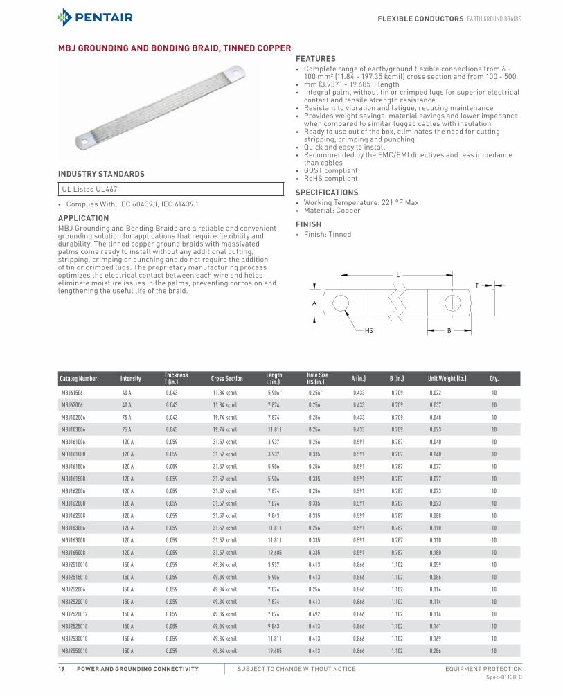
mbJ GroundinG and bondinG braid, tinned CoPPer
industry standards
UL Listed UL467
• complies With: iec 60439.1, iec 61439.1
aPPliCationmBJ Grounding and Bonding Braids are a reliable and convenient grounding solution for applications that require flexibility and durability. the tinned copper ground braids with massivated palms come ready to install without any additional cutting, stripping, crimping or punching and do not require the addition of tin or crimped lugs. the proprietary manufacturing process optimizes the electrical contact between each wire and helps eliminate moisture issues in the palms, preventing corrosion and lengthening the useful life of the braid.
Features• complete range of earth/ground flexible connections from 6 -
100 mm² (11.84 - 197.35 kcmil) cross section and from 100 - 500• mm (3.937” - 19.685”) length• integral palm, without tin or crimped lugs for superior electrical
contact and tensile strength resistance• resistant to vibration and fatigue, reducing maintenance• Provides weight savings, material savings and lower impedance
when compared to similar lugged cables with insulation• ready to use out of the box, eliminates the need for cutting,
stripping, crimping and punching• Quick and easy to install• recommended by the emc/emi directives and less impedance
than cables• GoSt compliant• roHS compliant
sPeCiFiCations• Working temperature: 221 °F max• material: copper
Finish• Finish: tinned
Catalog Number Intensity Thickness T (in.) Cross Section Length
L (in.)Hole Size HS (in.) A (in.) B (in.) Unit Weight (lb.) Qty.
MBJ61506 40 A 0.043 11.84 kcmil 5.906" 0.256" 0.433 0.709 0.022 10
MBJ62006 40 A 0.043 11.84 kcmil 7.874 0.256 0.433 0.709 0.037 10
MBJ102006 75 A 0.043 19.74 kcmil 7.874 0.256 0.433 0.709 0.048 10
MBJ103006 75 A 0.043 19.74 kcmil 11.811 0.256 0.433 0.709 0.073 10
MBJ161006 120 A 0.059 31.57 kcmil 3.937 0.256 0.591 0.787 0.040 10
MBJ161008 120 A 0.059 31.57 kcmil 3.937 0.335 0.591 0.787 0.040 10
MBJ161506 120 A 0.059 31.57 kcmil 5.906 0.256 0.591 0.787 0.077 10
MBJ161508 120 A 0.059 31.57 kcmil 5.906 0.335 0.591 0.787 0.077 10
MBJ162006 120 A 0.059 31.57 kcmil 7.874 0.256 0.591 0.787 0.073 10
MBJ162008 120 A 0.059 31.57 kcmil 7.874 0.335 0.591 0.787 0.073 10
MBJ162508 120 A 0.059 31.57 kcmil 9.843 0.335 0.591 0.787 0.088 10
MBJ163006 120 A 0.059 31.57 kcmil 11.811 0.256 0.591 0.787 0.110 10
MBJ163008 120 A 0.059 31.57 kcmil 11.811 0.335 0.591 0.787 0.110 10
MBJ165008 120 A 0.059 31.57 kcmil 19.685 0.335 0.591 0.787 0.180 10
MBJ2510010 150 A 0.059 49.34 kcmil 3.937 0.413 0.866 1.102 0.059 10
MBJ2515010 150 A 0.059 49.34 kcmil 5.906 0.413 0.866 1.102 0.086 10
MBJ252006 150 A 0.059 49.34 kcmil 7.874 0.256 0.866 1.102 0.114 10
MBJ2520010 150 A 0.059 49.34 kcmil 7.874 0.413 0.866 1.102 0.114 10
MBJ2520012 150 A 0.059 49.34 kcmil 7.874 0.492 0.866 1.102 0.114 10
MBJ2525010 150 A 0.059 49.34 kcmil 9.843 0.413 0.866 1.102 0.141 10
MBJ2530010 150 A 0.059 49.34 kcmil 11.811 0.413 0.866 1.102 0.169 10
MBJ2550010 150 A 0.059 49.34 kcmil 19.685 0.413 0.866 1.102 0.286 10
Flexible ConduCtors eArth Ground brAids
Spec-01138 CPH 763.422.2211 • FAX 763.422.2600 • PentAirProtect.comEQUIPMENT PROTECTION Power and GroundinG ConneCtivity 20
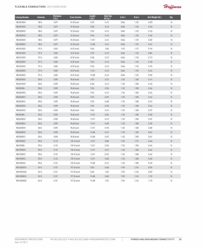
Catalog Number Intensity Thickness T (in.) Cross Section Length
L (in.)Hole Size HS (in.) A (in.) B (in.) Unit Weight (lb.) Qty.
MBJ3010010 180 A 0.079 59.20 kcmil 3.937 0.413 0.866 1.102 0.070 10
MBJ3015010 180 A 0.079 59.20 kcmil 5.906 0.413 0.866 1.102 0.103 10
MBJ3020010 180 A 0.079 59.20 kcmil 7.874 0.413 0.866 1.102 0.136 10
MBJ3025010 180 A 0.079 59.20 kcmil 9.843 0.413 0.866 1.102 0.165 10
MBJ3030010 180 A 0.079 59.20 kcmil 11.811 0.413 0.866 1.102 0.202 10
MBJ3050010 180 A 0.079 59.20 kcmil 19.685 0.413 0.866 1.102 0.341 10
MBJ3525025 197 A 0.059 69.07 kcmil 9.843 1.004 1.575 1.772 0.196 10
MBJ3510010 197 A 0.083 69.07 kcmil 3.937 0.413 0.866 1.102 0.081 10
MBJ3515010 197 A 0.083 69.07 kcmil 5.906 0.413 0.866 1.102 0.119 10
MBJ3520010 197 A 0.083 69.07 kcmil 7.874 0.413 0.866 1.102 0.158 10
MBJ3525010 197 A 0.083 69.07 kcmil 9.843 0.413 0.866 1.102 0.196 10
MBJ3530010 197 A 0.083 69.07 kcmil 11.811 0.413 0.866 1.102 0.242 10
MBJ3550010 197 A 0.083 69.07 kcmil 19.685 0.413 0.866 1.102 0.396 10
MBJ5010010 250 A 0.098 98.68 kcmil 3.937 0.413 1.102 1.300 0.114 10
MBJ5015010 250 A 0.098 98.68 kcmil 5.906 0.413 1.102 1.300 0.169 10
MBJ502006 250 A 0.098 98.68 kcmil 7.874 0.256 1.102 1.300 0.264 10
MBJ5020010 250 A 0.098 98.68 kcmil 7.874 0.413 1.102 1.300 0.264 10
MBJ5020012 250 A 0.098 98.68 kcmil 7.874 0.492 1.102 1.300 0.264 10
MBJ5020016 250 A 0.098 98.68 kcmil 7.874 0.650 1.102 1.300 0.242 10
MBJ5020018 250 A 0.098 98.68 kcmil 7.874 0.728 1.102 1.300 0.242 10
MBJ5025010 250 A 0.098 98.68 kcmil 9.843 0.413 1.102 1.300 0.279 10
MBJ503006 250 A 0.098 98.68 kcmil 11.811 0.256 1.102 1.300 0.330 10
MBJ5030010 250 A 0.098 98.68 kcmil 11.811 0.413 1.102 1.300 0.337 10
MBJ5030016 250 A 0.098 98.68 kcmil 11.811 0.650 1.102 1.300 0.330 10
MBJ5030018 250 A 0.098 98.68 kcmil 11.811 0.728 1.102 1.300 0.308 10
MBJ5050010 250 A 0.098 98.68 kcmil 19.685 0.413 1.102 1.300 0.561 10
MBJ5050012 250 A 0.098 98.68 kcmil 19.685 0.492 1.102 1.300 0.561 10
MBJ7030022 290 A 0.110 138.15 kcmil 11.811 0.886 1.575 1.772 0.440 10
MBJ703006 290 A 0.133 138.15 kcmil 11.811 0.256 1.102 1.300 0.462 10
MBJ7030010 290 A 0.133 138.15 kcmil 11.811 0.413 1.102 1.300 0.462 10
MBJ7030012 290 A 0.133 138.15 kcmil 11.811 0.492 1.102 1.300 0.462 10
MBJ7030016 290 A 0.133 138.15 kcmil 11.811 0.650 1.102 1.300 0.440 10
MBJ7050010 290 A 0.133 138.15 kcmil 19.685 0.413 1.102 1.300 0.748 10
MBJ10025016 349 A 0.157 197.35 kcmil 9.843 0.650 1.969 2.165 0.559 10
MBJ10025030 349 A 0.157 197.35 kcmil 9.843 1.201 1.969 2.165 0.559 10
MBJ10050016 349 A 0.157 197.35 kcmil 19.685 0.650 1.969 2.165 1.118 10
MBJ10050030 349 A 0.157 197.35 kcmil 19.685 1.201 1.969 2.165 1.118 10

Flexible ConduCtors eArth Ground brAids
Spec-01138 CEQUIPMENT PROTECTIONSUBJECT TO CHANGE WITHOUT NOTICEPower and GroundinG ConneCtivity21
CPi GroundinG and bondinG braid, stainless steel
industry standards• certification Details: UL 467• complies With: iec 60439.1, iec 61439.1
aPPliCationHigh-quality cPi stainless steel grounding and bonding braids can be installed in extremely corrosive environments, like offshoreapplications or coastal applications. the full range of cPi braids are ideal for applications using stainless steel pipe or tanks, like the food and beverage industry, building industry, transportation, oil and chemical industry.Hoffman offers 316L stainless steel braids and lugs, one of the highest resistant stainless steel options on the market. Proprietary manufacturing process has been optimized to provide the best braiding, crimping, cutting and punching.
Features• Superior abrasion, corrosion, chemical and UV resistance make
cPi braids ideal for outdoor applications• Great for expansion joints where constant movement requires a
flexible and durable solution• ready to use out of the box, eliminates the need for cutting,
stripping, crimping and punching• Quick and easy to install• resistant to vibration and fatigue, reducing maintenance• Will not rust or discolor, so the appearance will never fade or
change• excellent electrical contact• no additional lugs or terminals needed• non-magnetic material• recommended by the emc/emi directives• GoSt compliant• roHS compliant
sPeCiFiCations• material: Stainless Steel 316L (en 1.4404)
Catalog Number Cross Section Length L (in.)
Hole Size HS (in.) A (in.) B (in.) C (in.) D (in.) Unit Weight (lb.) Qty.
CPI161508 31.57 kcmil 5.906 0.335 0.689 0.787 0.394 0.118 0.068 10
CPI162008 31.57 kcmil 7.874 0.335 0.689 0.787 0.394 0.118 0.082 10
CPI162508 31.57 kcmil 9.843 0.335 0.689 0.787 0.394 0.118 0.095 10
CPI163008 31.57 kcmil 11.811 0.335 0.689 0.787 0.394 0.118 0.11 10
CPI164008 31.57 kcmil 15.748 0.335 0.689 0.787 0.394 0.118 0.137 10
CPI166008 31.57 kcmil 23.622 0.335 0.689 0.787 0.394 0.118 0.192 10
CPI2515010 49.34 kcmil 5.906 0.413 1.043 1.181 0.591 0.138 0.128 10
CPI2520010 49.34 kcmil 7.874 0.413 1.043 1.181 0.591 0.138 0.15 10
CPI2525010 49.34 kcmil 9.843 0.413 1.043 1.181 0.591 0.138 0.172 10
CPI2530010 49.34 kcmil 11.811 0.413 1.043 1.181 0.591 0.138 0.194 10
CPI2540010 49.34 kcmil 15.748 0.413 1.043 1.181 0.591 0.138 0.238 10
CPI2560010 49.34 kcmil 23.622 0.413 1.043 1.181 0.591 0.138 0.324 10
CPI3515012 69.07 kcmil 5.906 0.512 1.043 1.181 0.591 0.157 0.157 10
CPI3520012 69.07 kcmil 7.874 0.512 1.043 1.181 0.591 0.157 0.187 10
CPI3525012 69.07 kcmil 9.843 0.512 1.043 1.181 0.591 0.157 0.218 10
CPI3530012 69.07 kcmil 11.811 0.512 1.043 1.181 0.591 0.157 0.247 10
CPI3540012 69.07 kcmil 15.748 0.512 1.043 1.181 0.591 0.157 0.309 10
CPI3560012 69.07 kcmil 23.622 0.512 1.043 1.181 0.591 0.157 0.43 10
CPI5015012 98.68 kcmil 5.906 0.512 1.181 1.181 0.591 0.197 0.245 10
CPI5020012 98.68 kcmil 7.874 0.512 1.181 1.181 0.591 0.197 0.287 10
CPI5025012 98.68 kcmil 9.843 0.512 1.181 1.181 0.591 0.197 0.331 10
CPI5030012 98.68 kcmil 11.811 0.512 1.181 1.181 0.591 0.197 0.375 10
CPI5040012 98.68 kcmil 15.748 0.512 1.181 1.181 0.591 0.197 0.461 10
CPI5060012 98.68 kcmil 23.622 0.512 1.181 1.181 0.591 0.197 0.635 10

Flexible ConduCtors eArth Ground brAids
Spec-01138 CPH 763.422.2211 • FAX 763.422.2600 • PentAirProtect.comEQUIPMENT PROTECTION Power and GroundinG ConneCtivity 22
Catalog Number Cross Section Length L (in.)
Hole Size HS (in.) A (in.) B (in.) C (in.) D (in.) Unit Weight (lb.) Qty.
CPI70110012 138.15 kcmil 43.307 0.512 1.181 1.181 0.591 0.228 1.464 10
CPI7015012 138.15 kcmil 5.906 0.512 1.181 1.181 0.591 0.228 0.306 10
CPI7020012 138.15 kcmil 7.874 0.512 1.181 1.181 0.591 0.228 0.368 10
CPI7025012 138.15 kcmil 9.843 0.512 1.181 1.181 0.591 0.228 0.428 10
CPI7030012 138.15 kcmil 11.811 0.512 1.181 1.181 0.591 0.228 0.489 10
CPI7040012 138.15 kcmil 15.748 0.512 1.181 1.181 0.591 0.228 0.611 10
CPI7060012 138.15 kcmil 23.622 0.512 1.181 1.181 0.591 0.228 0.855 10
CPI7080012 138.15 kcmil 31.496 0.512 1.181 1.181 0.591 0.228 1.098 10
bJ round braid with CrimPed luGs
Features• ready to use out of the box, saving installation time and labor• • recommended by the emc directives• • Allows for bending very close to the contact area• • roHS compliant
sPeCiFiCations• material: copper• Working temperature: 221 °F max
Finish• Finish: tinned
Catalog Number Intensity Cross Section Length L (in.) Wire Diameter (in.) Hole SizeHS (in.) Unit Weight(lb.) Qty.
BJ6150S 45 A 11.84 kcmil 5.91 0.006 0.26 0.02 10
BJ6200S 45 A 11.84 kcmil 7.87 0.006 0.26 0.03 10
BJ10300S 75 A 19.74 kcmil 11.81 0.006 0.26 0.07 10
Flexible ConduCtors Power shunts
Spec-01138 CEQUIPMENT PROTECTIONSUBJECT TO CHANGE WITHOUT NOTICEPower and GroundinG ConneCtivity23
Power shunts
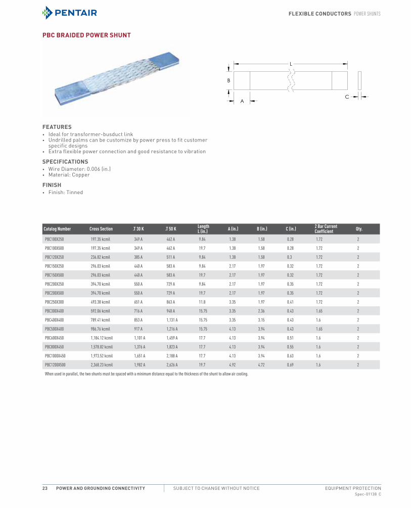
PbC braided Power shunt
Features• ideal for transformer-busduct link• Undrilled palms can be customize by power press to fit customer
specific designs• extra flexible power connection and good resistance to vibration
sPeCiFiCations• Wire Diameter: 0.006 (in.)• material: copper
Finish• Finish: tinned
Catalog Number Cross Section .T 30 K .T 50 K Length L (in.) A (in.) B (in.) C (in.) 2 Bar Current
Coefficient Qty.
PBC100X250 197.35 kcmil 349 A 462 A 9.84 1.38 1.58 0.28 1.72 2
PBC100X500 197.35 kcmil 349 A 462 A 19.7 1.38 1.58 0.28 1.72 2
PBC120X250 236.82 kcmil 385 A 511 A 9.84 1.38 1.58 0.3 1.72 2
PBC150X250 296.03 kcmil 440 A 583 A 9.84 2.17 1.97 0.32 1.72 2
PBC150X500 296.03 kcmil 440 A 583 A 19.7 2.17 1.97 0.32 1.72 2
PBC200X250 394.70 kcmil 550 A 729 A 9.84 2.17 1.97 0.35 1.72 2
PBC200X500 394.70 kcmil 550 A 729 A 19.7 2.17 1.97 0.35 1.72 2
PBC250X300 493.38 kcmil 651 A 863 A 11.8 3.35 1.97 0.41 1.72 2
PBC300X400 592.06 kcmil 716 A 948 A 15.75 3.35 2.36 0.43 1.65 2
PBC400X400 789.41 kcmil 853 A 1,131 A 15.75 3.35 3.15 0.43 1.6 2
PBC500X400 986.76 kcmil 917 A 1,216 A 15.75 4.13 3.94 0.43 1.65 2
PBC600X450 1,184.12 kcmil 1,101 A 1,459 A 17.7 4.13 3.94 0.51 1.6 2
PBC800X450 1,578.82 kcmil 1,376 A 1,823 A 17.7 4.13 3.94 0.55 1.6 2
PBC1000X450 1,973.52 kcmil 1,651 A 2,188 A 17.7 4.13 3.94 0.63 1.6 2
PBC1200X500 2,368.23 kcmil 1,982 A 2,626 A 19.7 4.92 4.72 0.69 1.6 2
When used in parallel, the two shunts must be spaced with a minimum distance equal to the thickness of the shunt to allow air cooling.
Flexible ConduCtors FlAt brAids
Spec-01138 CPH 763.422.2211 • FAX 763.422.2600 • PentAirProtect.comEQUIPMENT PROTECTION Power and GroundinG ConneCtivity 24
FlAt brAids
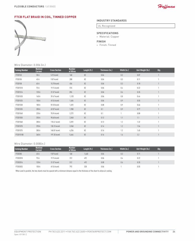
FtCb Flat braid in Coil, tinned CoPPerindustry standards
UL recognized
sPeCiFiCations• material: copper
Finish• Finish: tinned
Wire Diameter: 0.006 (in.)
Catalog Number NominalCurrent Cross Section Number
of Wires Length (ft.) Thickness (in.) Width (in.) Unit Weight (lb.) Qty.
FTCB153 30 A 5.92 kcmil 168 82 0.04 0.2 0.07 1
FTCB155 45 A 9.87 kcmil 288 82 0.04 0.3 0.11 1
FTCB158 65 A 15.78 kcmil 456 82 0.06 0.3 0.18 1
FTCB1510 75 A 19.74 kcmil 576 82 0.06 0.4 0.22 1
FTCB1516 120 A 31.57 kcmil 896 82 0.06 0.6 0.35 1
FTCB1520 140 A 39.47 kcmil 1,120 82 0.06 0.8 0.44 1
FTCB1525 150 A 49.34 kcmil 1,404 82 0.06 0.9 0.55 1
FTCB1530 180 A 59.20 kcmil 1,692 82 0.08 0.9 0.66 1
FTCB1535 200 A 69.07 kcmil 1,980 82 0.1 0.9 0.77 1
FTCB1540 220 A 78.94 kcmil 2,272 82 0.1 1 0.88 1
FTCB1550 250 A 98.68 kcmil 2,848 82 0.12 1.1 1.1 1
FTCB1560 280 A 118.41 kcmil 3,392 82 0.12 1.2 1.32 1
FTCB1570 290 A 138.15 kcmil 3,968 82 0.14 1.2 1.54 1
FTCB1575 300 A 148.01 kcmil 4,256 82 0.16 1.2 1.65 1
FTCB15100 360 A 197.35 kcmil 5,664 82 0.16 1.6 2.2 1
Wire Diameter: 0.008(in.)
Catalog Number NominalCurrent Cross Section Number
of Wires Length (ft.) Thickness (in.) Width (in.) Unit Weight (lb.) Qty.
FTCB205 45 A 9.87 kcmil 168 1,640 0.04 0.3 0.11 1
FTCB2010 75 A 19.74 kcmil 312 492 0.06 0.4 0.22 1
FTCB2016 120 A 31.57 kcmil 512 492 0.08 0.6 0.35 1
FTCB2025 150 A 49.34 kcmil 792 328 0.06 1 0.55 1
When used in parallel, the two shunts must be spaced with a minimum distance equal to the thickness of the shunt to allow air cooling.
Flexible ConduCtors FlAt brAids
Spec-01138 CEQUIPMENT PROTECTIONSUBJECT TO CHANGE WITHOUT NOTICEPower and GroundinG ConneCtivity25
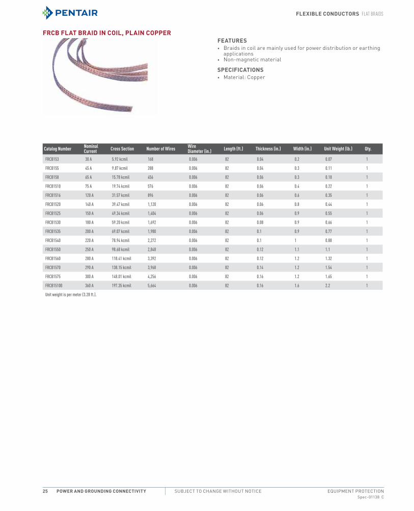
FrCb Flat braid in Coil, Plain CoPPerFeatures• Braids in coil are mainly used for power distribution or earthing
applications• non-magnetic material
sPeCiFiCations• material: copper
Catalog Number Nominal Current Cross Section Number of Wires Wire
Diameter (in.) Length (ft.) Thickness (in.) Width (in.) Unit Weight (lb.) Qty.
FRCB153 30 A 5.92 kcmil 168 0.006 82 0.04 0.2 0.07 1
FRCB155 45 A 9.87 kcmil 288 0.006 82 0.04 0.3 0.11 1
FRCB158 65 A 15.78 kcmil 456 0.006 82 0.06 0.3 0.18 1
FRCB1510 75 A 19.74 kcmil 576 0.006 82 0.06 0.4 0.22 1
FRCB1516 120 A 31.57 kcmil 896 0.006 82 0.06 0.6 0.35 1
FRCB1520 140 A 39.47 kcmil 1,120 0.006 82 0.06 0.8 0.44 1
FRCB1525 150 A 49.34 kcmil 1,404 0.006 82 0.06 0.9 0.55 1
FRCB1530 180 A 59.20 kcmil 1,692 0.006 82 0.08 0.9 0.66 1
FRCB1535 200 A 69.07 kcmil 1,980 0.006 82 0.1 0.9 0.77 1
FRCB1540 220 A 78.94 kcmil 2,272 0.006 82 0.1 1 0.88 1
FRCB1550 250 A 98.68 kcmil 2,848 0.006 82 0.12 1.1 1.1 1
FRCB1560 280 A 118.41 kcmil 3,392 0.006 82 0.12 1.2 1.32 1
FRCB1570 290 A 138.15 kcmil 3,968 0.006 82 0.14 1.2 1.54 1
FRCB1575 300 A 148.01 kcmil 4,256 0.006 82 0.16 1.2 1.65 1
FRCB15100 360 A 197.35 kcmil 5,664 0.006 82 0.16 1.6 2.2 1
Unit weight is per meter (3.28 ft.).

Flexible ConduCtors FlAt brAids
Spec-01138 CPH 763.422.2211 • FAX 763.422.2600 • PentAirProtect.comEQUIPMENT PROTECTION Power and GroundinG ConneCtivity 26
FtCbi insulated Flat braid in Coil, tinned CoPPerFeatures• Braids in coil are mainly used for power distribution or earthing
applications• non-magnetic material• tinned finish provides a theft-deterrent appearance
sPeCiFiCations• material: copper, Polyvinylchloride
Finish• Finish: tinned
Catalog Number Nominal Current Cross Section Number of Wires Wire
Diameter (in.) Length (in.) Thickness (in.) Width (in.) Unit Weight (lb.) Qty.
FTCBI16 120 A 31.57 kcmil 896 0.006 82 0.14 0.7 0.4 1
FTCBI1516 120 A 31.57 kcmil 896 0.006 328 0.14 0.7 0.4 1
FTCBI25 150 A 49.34 kcmil 1,404 0.006 82 0.14 1 0.64 1
FTCBI1525 150 A 49.34 kcmil 1,404 0.006 328 0.14 1 0.64 1
FTCBI35 200 A 69.07 kcmil 1,980 0.006 82 0.18 1 0.88 1
FTCBI50 250 A 98.68 kcmil 2,848 0.006 82 0.2 1.2 1.32 1
Insulation Thickness (in.) Insulation Voltage Temperature Flammability Rating0.04 450 V 158 °F Max UL 94V0
Unit weight is per meter (3.28 ft.).
Fssb Flat braid in Coil, stainless steelindustry standards
UL recognized
Features• High-quality durable stainless steel 316L provides superior
abrasion, corrosion, chemical, and UV resistance for outdoor and• corrosive applications• non-magnetic material• Duribility of product lengthens cycle time between maintainance
sPeCiFiCations• material: Stainless Steel 316L (en 1.4404)
Catalog Number Cross Section Wire Diameter (in.) Length (ft.) Thickness (in.) Width (in.) Unit Weight(lb.) Qty.FSSB2516 31.57 kcmil 0.01 82 0.06 0.6 0.3 1
FSSB2525 49.34 kcmil 0.01 82 0.06 0.9 0.49 1
FSSB2550 98.68 kcmil 0.01 82 0.12 1.2 0.97 1
Unit weight is per meter (3.28 ft.).

Flexible ConduCtors round brAids
Spec-01138 CEQUIPMENT PROTECTIONSUBJECT TO CHANGE WITHOUT NOTICEPower and GroundinG ConneCtivity27
round brAids
rtCb round braid in Coil, tinned CoPPerindustry standards
UL recognized
sPeCiFiCations• material: copper
Finish• Finish: tinned
Catalog Number Nominal Current Cross Section Number of Wires Wire Diameter (in.) Length (ft.) Diameter (in.) Unit Weight (lb.) Qty.
RTCB156 45 A 11.84 kcmil 352 0.006 82 0.157 0.13 1
RTCB158 65 A 15.78 kcmil 464 0.006 82 0.177 0.18 1
RTCB1510 75 A 19.74 kcmil 560 0.006 82 0.197 0.22 1
RTCB1510HL 75 A 19.74 kcmil 560 0.006 328 0.197 0.22 1
RTCB1516 120 A 31.57 kcmil 900 0.006 82 0.236 0.35 1
RTCB1516HL 120 A 31.57 kcmil 900 0.006 328 0.236 0.35 1
RTCB1525 150 A 49.34 kcmil 1,416 0.006 82 0.315 0.55 1
RTCB1525HL 150 A 49.34 kcmil 1,416 0.006 328 0.295 0.55 1
RTCB1530 180 A 59.20 kcmil 1,680 0.006 82 0.354 0.66 1
RTCB1530HL 180 A 59.20 kcmil 1,680 0.006 246 0.31 0.66 1
RTCB1550 250 A 98.68 kcmil 2,820 0.006 82 0.433 1.1 1
RTCB1575 300 A 148.01 kcmil 4,236 0.006 82 0.531 1.65 1
RTCB15100 360 A 197.35 kcmil 5,652 0.006 82 0.669 2.2 1
Unit weight is per meter (3.28 ft.).
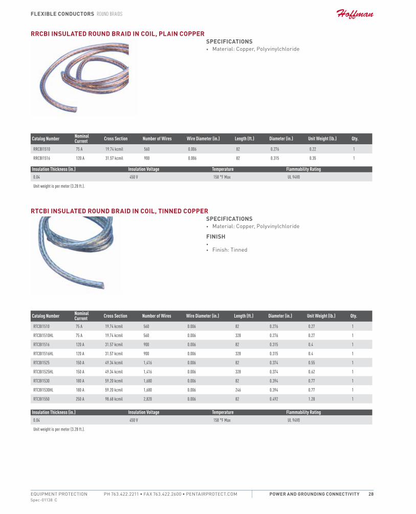
rrCb round braid in Coil, Plain CoPPerFeatures• Braids in coil are mainly used for power distribution or earthing
applications• non-magnetic material
sPeCiFiCations• material: copper
Catalog Number Nominal Current Cross Section Number of Wires Wire Diameter (in.) Length (ft.) Diameter (in.) Unit Weight (lb.) Qty.
RRCB156 45 A 11.84 kcmil 352 0.006 82 0.157 0.13 1
RRCB158 65 A 15.78 kcmil 464 0.006 82 0.177 0.18 1
RRCB1510 75 A 19.74 kcmil 560 0.006 82 0.197 0.22 1
RRCB1516 120 A 31.57 kcmil 900 0.006 82 0.236 0.35 1
RRCB1525 150 A 49.34 kcmil 1,416 0.006 82 0.315 0.55 1
RRCB1530 180 A 59.20 kcmil 1,680 0.006 82 0.354 0.66 1
RRCB1550 250 A 98.68 kcmil 2,820 0.006 82 0.433 1.1 1
RRCB1575 300 A 148.01 kcmil 4,236 0.006 82 0.551 1.65 1
RRCB15100 360 A 197.35 kcmil 5,652 0.006 82 0.709 2.2 1
Unit weight is per meter (3.28 ft.).
Flexible ConduCtors round brAids
Spec-01138 CPH 763.422.2211 • FAX 763.422.2600 • PentAirProtect.comEQUIPMENT PROTECTION Power and GroundinG ConneCtivity 28
rrCbi insulated round braid in Coil, Plain CoPPersPeCiFiCations• material: copper, Polyvinylchloride
Catalog Number Nominal Current Cross Section Number of Wires Wire Diameter (in.) Length (ft.) Diameter (in.) Unit Weight (lb.) Qty.
RRCBI1510 75 A 19.74 kcmil 560 0.006 82 0.276 0.22 1
RRCBI1516 120 A 31.57 kcmil 900 0.006 82 0.315 0.35 1
Insulation Thickness (in.) Insulation Voltage Temperature Flammability Rating0.04 450 V 158 °F Max UL 94V0
Unit weight is per meter (3.28 ft.).
rtCbi insulated round braid in Coil, tinned CoPPersPeCiFiCations• material: copper, Polyvinylchloride
Finish• • Finish: tinned
Catalog Number Nominal Current Cross Section Number of Wires Wire Diameter (in.) Length (ft.) Diameter (in.) Unit Weight (lb.) Qty.
RTCBI1510 75 A 19.74 kcmil 560 0.006 82 0.276 0.27 1
RTCBI1510HL 75 A 19.74 kcmil 560 0.006 328 0.276 0.27 1
RTCBI1516 120 A 31.57 kcmil 900 0.006 82 0.315 0.4 1
RTCBI1516HL 120 A 31.57 kcmil 900 0.006 328 0.315 0.4 1
RTCBI1525 150 A 49.34 kcmil 1,416 0.006 82 0.374 0.55 1
RTCBI1525HL 150 A 49.34 kcmil 1,416 0.006 328 0.374 0.62 1
RTCBI1530 180 A 59.20 kcmil 1,680 0.006 82 0.394 0.77 1
RTCBI1530HL 180 A 59.20 kcmil 1,680 0.006 246 0.394 0.77 1
RTCBI1550 250 A 98.68 kcmil 2,820 0.006 82 0.492 1.28 1
Insulation Thickness (in.) Insulation Voltage Temperature Flammability Rating0.04 450 V 158 °F Max UL 94V0
Unit weight is per meter (3.28 ft.).
Flexible ConduCtors round brAids
Spec-01138 CEQUIPMENT PROTECTIONSUBJECT TO CHANGE WITHOUT NOTICEPower and GroundinG ConneCtivity29
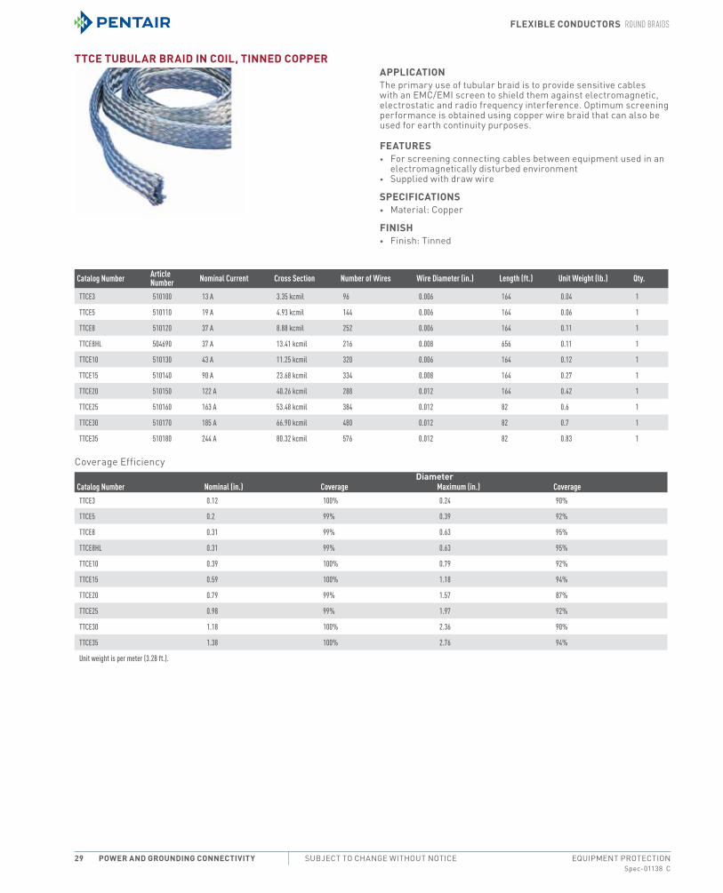
ttCe tubular braid in Coil, tinned CoPPeraPPliCationthe primary use of tubular braid is to provide sensitive cables with an emc/emi screen to shield them against electromagnetic, electrostatic and radio frequency interference. optimum screening performance is obtained using copper wire braid that can also be used for earth continuity purposes.
Features• For screening connecting cables between equipment used in an
electromagnetically disturbed environment• Supplied with draw wire
sPeCiFiCations• material: copper
Finish• Finish: tinned
Catalog Number Article Number Nominal Current Cross Section Number of Wires Wire Diameter (in.) Length (ft.) Unit Weight (lb.) Qty.
TTCE3 510100 13 A 3.35 kcmil 96 0.006 164 0.04 1
TTCE5 510110 19 A 4.93 kcmil 144 0.006 164 0.06 1
TTCE8 510120 37 A 8.88 kcmil 252 0.006 164 0.11 1
TTCE8HL 504690 37 A 13.41 kcmil 216 0.008 656 0.11 1
TTCE10 510130 43 A 11.25 kcmil 320 0.006 164 0.12 1
TTCE15 510140 90 A 23.68 kcmil 334 0.008 164 0.27 1
TTCE20 510150 122 A 40.26 kcmil 288 0.012 164 0.42 1
TTCE25 510160 163 A 53.48 kcmil 384 0.012 82 0.6 1
TTCE30 510170 185 A 66.90 kcmil 480 0.012 82 0.7 1
TTCE35 510180 244 A 80.32 kcmil 576 0.012 82 0.83 1
coverage efficiencydiameter
Catalog Number Nominal (in.) Coverage Maximum (in.) CoverageTTCE3 0.12 100% 0.24 90%
TTCE5 0.2 99% 0.39 92%
TTCE8 0.31 99% 0.63 95%
TTCE8HL 0.31 99% 0.63 95%
TTCE10 0.39 100% 0.79 92%
TTCE15 0.59 100% 1.18 94%
TTCE20 0.79 99% 1.57 87%
TTCE25 0.98 99% 1.97 92%
TTCE30 1.18 100% 2.36 90%
TTCE35 1.38 100% 2.76 94%
Unit weight is per meter (3.28 ft.).
Flexible ConduCtors MAke Your own brAided ConneCtions
Spec-01138 CPH 763.422.2211 • FAX 763.422.2600 • PentAirProtect.comEQUIPMENT PROTECTION Power and GroundinG ConneCtivity 30
MAke Your own brAided ConneCtions
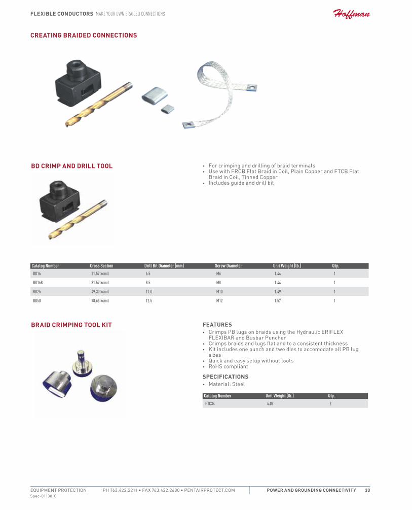
CreatinG braided ConneCtions
bd CrimP and drill tool • For crimping and drilling of braid terminals• Use with FrcB Flat Braid in coil, Plain copper and FtcB Flat
Braid in coil, tinned copper• includes guide and drill bit
Catalog Number Cross Section Drill Bit Diameter (mm) Screw Diameter Unit Weight (lb.) Qty.BD16 31.57 kcmil 6.5 M6 1.44 1
BD168 31.57 kcmil 8.5 M8 1.44 1
BD25 49.30 kcmil 11.0 M10 1.49 1
BD50 98.68 kcmil 12.5 M12 1.57 1
braid CrimPinG tool Kit Features• crimps PB lugs on braids using the Hydraulic eriFLeX
FLeXiBAr and Busbar Puncher• crimps braids and lugs flat and to a consistent thickness• Kit includes one punch and two dies to accomodate all PB lug
sizes• Quick and easy setup without tools• roHS compliant
sPeCiFiCations• material: Steel
Catalog Number Unit Weight (lb.) Qty.HTC34 4.09 2
Flexible ConduCtors MAke Your own brAided ConneCtions
Spec-01138 CEQUIPMENT PROTECTIONSUBJECT TO CHANGE WITHOUT NOTICEPower and GroundinG ConneCtivity31
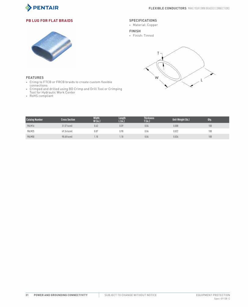
Pb luG For Flat braids
Features• crimp to FtcB or FrcB braids to create custom flexible
connections• crimped and drilled using BD crimp and Drill tool or crimping
tool for Hydraulic Work center• roHS compliant
sPeCiFiCations• material: copper
Finish• Finish: tinned
Catalog Number Cross Section Width W (in.)
Length L (in.)
Thickness T (in.) Unit Weight (lb.) Qty.
PALM16 31.57 kcmil 0.63 0.59 0.04 0.008 100
PALM25 49.34 kcmil 0.87 0.98 0.04 0.022 100
PALM50 98.68 kcmil 1.18 1.18 0.04 0.034 100

Flexible ConduCtors MAke Your own brAided ConneCtions
Spec-01138 CPH 763.422.2211 • FAX 763.422.2600 • PentAirProtect.comEQUIPMENT PROTECTION Power and GroundinG ConneCtivity 32
notes