flexible and efficient computer-aided design tool...
TRANSCRIPT
1
Article published in Int. Journal of RF and Microwave Computer-Aided Engineering, vol. 25, pp. 696-708, 2015
Flexible and Efficient Computer-Aided Design Tool for Advanced Comb-Line Rectangular Waveguide Filters
A. A. San-Blas1, A. Vidal2, A. A. Muller2, P. Soto2, F. Mira3,
J. Pérez-Soler4, B. Gimeno5, and V. E. Boria2
1Departamento de Ingeniería de Comunicaciones, Universidad Miguel Hernández de Elche, Elche, Spain (Corresponding author: [email protected])
2Departamento de Comunicaciones - iTEAM, Universidad Politécnica de Valencia, Valencia, Spain ([email protected], [email protected], [email protected], [email protected])
3Centre Tecnològic de Telecomunicacions de Catalunya, Barcelona, Spain ([email protected])
4Aurora Software and Testing S. L., Valencia, Spain ([email protected]) 5Departamento de Física Aplicada y Electromagnetismo – ICMUV Universidad de Valencia, Valencia, Spain ([email protected])
Abstract ─ A very flexible and efficient computer-aided design (CAD) tool, specifically suited for advanced comb-line rectangular waveguide filters, is presented in this work. The developed software tool, which makes use of a full-wave analysis technique based on the Boundary Integral - Resonant Mode Expansion method, permits to load the considered comb-line resonators with any number of radially symmetrical partial-height metallic posts. The implemented CAD tool also allows for dealing with coupling windows of arbitrary cross-section, thus drastically enhancing the flexibility of the computer-aided design process. The excitation of the analyzed components, which is performed by using generalized coaxial probes, has also been integrated in the implemented software tool, thus achieving a full-wave electromagnetic characterization of the whole component. Furthermore, a novel simple procedure to efficiently connect all the obtained wide-band matrices is proposed. In order to validate the accuracy and efficiency of this novel CAD tool, several new designs concerning advanced band-pass comb-line waveguide filters are presented. The accuracy of the developed CAD tool has been successfully validated by comparing the obtained results with numerical data provided by a commercial tool based on the finite-element method. Index Terms – CAD tool, comb-line rectangular waveguide filters, full-wave analysis methods, wide-band matrices. I. INTRODUCTION
Rectangular waveguide components are frequently used in current space
communications devices in both microwave and millimeter wave range [1], [2]. The well-known comb-line topology is commonly used in critical receiver front-end applications, and it represents an excellent option for the input and output stages of current satellite payloads [3]. Besides, this waveguide technology offers some interesting advantages: a very compact size, a relatively low manufacturing cost, a great facility to adjust the center frequency of the passband of the filter over a wide frequency range, and a frequency response almost free of spurious [4]–[7]. Classical comb-line waveguide filters are composed of the interconnection of several boxed cavities generally loaded with partial-height metallic posts with a rectangular or a cylindrical geometry [8]. The electromagnetic coupling between the resonators of such filters is
2
achieved by introducing a set of irises whose cross-section usually has a rectangular geometry [8]. Furthermore, microwave researchers frequently resort to a cross-coupling configuration when designing folded comb-line filters with the aim of introducing additional transmission zeros. In this case, rectangular waveguide irises are also commonly used in order to increase the electric coupling level between the desired resonators [9].
In this manuscript, we present a novel and very flexible CAD tool (based on a
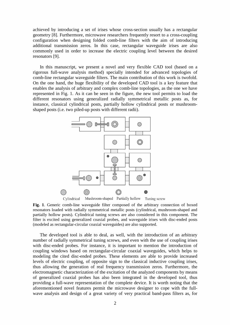
rigorous full-wave analysis method) specially intended for advanced topologies of comb-line rectangular waveguide filters. The main contribution of this work is twofold. On the one hand, the huge flexibility of the developed CAD tool is a key feature that enables the analysis of arbitrary and complex comb-line topologies, as the one we have represented in Fig. 1. As it can be seen in the figure, the new tool permits to load the different resonators using generalized radially symmetrical metallic posts as, for instance, classical cylindrical posts, partially hollow cylindrical posts or mushroom-shaped posts (i.e. two piled-up posts with different radii).
Fig. 1. Generic comb-line waveguide filter composed of the arbitrary connection of boxed resonators loaded with radially symmetrical metallic posts (cylindrical, mushroom-shaped and partially hollow posts). Cylindrical tuning screws are also considered in this component. The filter is excited using generalized coaxial probes, and waveguide irises with disc-ended posts (modeled as rectangular-circular coaxial waveguides) are also supported.
The developed tool is able to deal, as well, with the introduction of an arbitrary
number of radially symmetrical tuning screws, and even with the use of coupling irises with disc-ended probes. For instance, it is important to mention the introduction of coupling windows based on rectangular-circular coaxial waveguides, which helps to modeling the cited disc-ended probes. These elements are able to provide increased levels of electric coupling, of opposite sign to the classical inductive coupling irises, thus allowing the generation of real frequency transmission zeros. Furthermore, the electromagnetic characterization of the excitation of the analyzed components by means of generalized coaxial probes has also been integrated in the developed tool, thus providing a full-wave representation of the complete device. It is worth noting that the aforementioned novel features permit the microwave designer to cope with the full-wave analysis and design of a great variety of very practical band-pass filters as, for
3
instance, those based on conductor post insert reentrant coaxial resonators [5]. Even though the developed CAD tool is specially suited for the analysis and design of comb-line waveguide filters, it is important to indicate that it is able to cope, as well, with classical diplexers formed by side-coupled coaxial resonators [10]–[12], and with more advanced topologies of diplexers and multiplexers (for instance, those based on multiple connections among loaded resonators, recently proposed in [13], [14] but for empty boxed cavities). To the author’s knowledge, all the previously cited modifications with respect to the more classical geometries of comb-line filters, have not been investigated so far in the technical literature concerning the full-wave modal analysis of this type of components, and they can contribute to an optimum design of such structures, as it will be verified in the results section.
On the other hand, the second main contribution of this work is that, to the best
knowledge of the authors, the 3D Boundary Integral-Resonant Mode Expansion (BI-RME) method [15] has been used, for the first time, for the rigorous full-wave analysis of comb-line boxed resonators with an arbitrary number of ports (up to four) with a non-rectangular cross-section. For instance, a boxed cavity with two non-rectangular ports has been represented in the arbitrary topology shown in Fig. 1 (upper left hand side of the figure): one port is the coaxial line used to excite the component, and the other port is based on a rectangular-circular coaxial waveguide for modelling a disc-ended probe. To this respect, it should be pointed out that authors’ previous contributions concerning the full-wave analysis of waveguide filters by means of the 3D BI-RME technique, were restricted to the consideration of only one non-rectangular port (i.e. just the coaxial line) [16]. This key factor of the novel proposed CAD tool, which has required a considerable theoretical effort, notably enhances the flexibility of the developed software.
Furthermore, the wide-band matrices provided by the full-wave modal techniques
used to characterize the analyzed components are efficiently connected by means of a novel and simple procedure, thus generating a very efficient CAD tool in terms of consumed CPU resources. In order to validate the precision of the proposed CAD tool, several new designs of advanced comb-line waveguide filters are presented in this work. The obtained results are successfully compared to the simulated data provided by a commercial tool based on the finite-element method, thus demonstrating the accuracy of the implemented software tool.
II. FULL-WAVE ANALYSIS OF ADVANCED COMB-LINE WAVEGUIDE FILTERS LOADED WITH RADIALLY SYMMETRICAL POSTS
Next, the main capabilities of the new developed CAD tool are firstly described. Afterwards, the rigorous analysis of advanced comb-line waveguide filters using full-wave modal methods is presented in detail, and a novel and simple approach for the efficient connection of the obtained wide-band matrices is finally proposed.
A. Description of the developed CAD tool
The main aim of the implemented simulation tool is the full-wave modal analysis of
comb-line rectangular waveguide filters composed of an arbitrary number of boxed resonators, as it has been represented in Fig. 1. The different cavities can be

4
interconnected in any desired pattern, thus providing a very flexible CAD tool able to deal with the full-wave analysis of advanced topologies recently proposed for microwave devices [13]. The comb-line resonators can be loaded with radially symmetrical partial-height metallic posts, such as cylindrical posts, partially hollow posts and mushroom-shaped posts, as illustrated in Fig. 2 (note that more complex posts could be also considered). These loading posts can be located on any face of the boxed resonator, and there is no restriction about the number of considered posts. The comb-line resonators can also include an arbitrary number of radially symmetrical tuning screws as, for instance, the cylindrical tuning screw depicted in Fig. 2(c). It is worth mentioning that such topology (partially hollow post with an inserted tuning screw) is frequently used to design conductor post insert reentrant coaxial resonators [5].
The comb-line resonators are interconnected using coupling irises which can be
located at any lateral face of the cavities, thus allowing for the design of folded topologies with the option of including cross-couplings. Although classical comb-line filters are usually designed using rectangular waveguide coupling windows, a remarkable feature of the developed CAD tool is that it is able to consider waveguide irises of arbitrary cross-section.
(a) (b) (c)
Fig. 2. Radially symmetrical partial-height metallic posts supported by the implemented CAD tool: (a) cylindrical, (b) mushroom-shaped, and (c) partially hollow post. Note that a cylindrical tuning screw has been included in (c) to cope with the analysis of conductor post insert reentrant coaxial resonators, and that an arbitrary number of radially symmetrical tuning screws can be added in the cavities of (a) and (b).
For instance, a coupling iris based on a rectangular coaxial waveguide whose inner conductor has a circular geometry, has been represented in Fig. 3. In this example, the cited inner circular conductor couples the two desired resonators by means of disc-ended cylindrical posts.
Fig. 3. Example of a coupling iris between two adjacent resonators based on a rectangular coaxial waveguide with an inner circular conductor (for modeling a disc-ended probe).
5
Finally, with regard to the excitation of the component, the developed CAD tool is able to consider an arbitrary number of waveguide access ports, all of them of arbitrary cross-section. As classical comb-line waveguide filters are usually fed using collinear coaxial lines, the implemented CAD tool is, therefore, able to cope with generalized coaxial configurations as, for instance, the disc-ended coaxial probe displayed on the lower left hand side of Fig. 1.
B. Full-wave electromagnetic analysis of comb-line resonators
In recent years, the authors proposed a novel approach to analyze comb-line
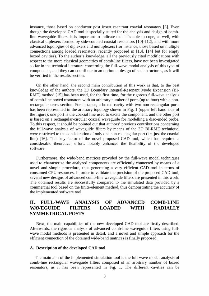
waveguide filters using full-wave methods [16]. It is important to mention that the tool presented in [16] was not able to cope with the analysis of boxed resonators loaded on its base surface with generalized radially symmetrical posts. In fact, all the designs presented in [16] were restricted to filters whose resonators were loaded with the classical cylindrical posts, as the electric current on the surface of the cited posts was represented using a set of entire-domain basis functions, which were suitable to deal only with such geometry [17]. In this work, the new set of basis functions proposed in [18] have been implemented, thus allowing for the rigorous modeling of the electric current present in generalized radially symmetrical posts. Additionally, the waveguide irises used in the designs presented in [16] were limited to a classical rectangular geometry. This new contribution eliminates this restriction, and coupling irises of arbitrary cross-section (i.e. a disc-ended probe) can be considered. As a result, this contribution represents a significant extension of the work developed in [16].
Fig. 4. Key building blocks of the developed CAD tool. Rectangular resonators loaded with generalized radially symmetrical posts, and with an integrated collinear coaxial line excitation. Waveguide irises of arbitrary cross-section can be also considered.
The key building blocks used to cope with the full-wave analysis of the advanced
comb-line waveguide filters under analysis are shown in Fig. 4, where two generic comb-line resonators loaded with generalized radially symmetrical posts have been depicted. In this case, one resonator is loaded with a mushroom-shaped metallic post, while the other cavity implements a conductor post insert reentrant coaxial resonator. It is important to remember that, in this work, the waveguide irises that may be present in the considered component can have an arbitrary cross-section (thus allowing to consider disc-ended coupling probes). To this respect, a coupling window based on a rectangular coaxial waveguide with an inner circular conductor has been depicted in Fig. 4. Besides, a collinear coaxial line access port has also been considered in this key building block to take into account the excitation of the structure, thus achieving a rigorous electromagnetic characterization of the whole component.

6
The strategy followed to address the multimodal characterization of the previously
described key building blocks combines the application of two highly efficient modal analysis methods: the integral equation technique [19], and the Boundary Integral-Resonant Mode Expansion (BI-RME) method (in its 2D and 3D versions) [15], [20], [21]. On the one hand, the 3D BI-RME method is used for the full-wave analysis of the rectangular resonators loaded with radially symmetrical posts [15]. This method is very efficient from a computational point of view, and it is frequently used in the analysis of lossless microwave devices with an arbitrary 3D geometry. The method provides an electromagnetic characterization of the analyzed structure in terms of a generalized admittance matrix (GAM) in the form of pole expansions:
,1 '
122
)()(3
∑= −
++=M
i i
iT
iBA
kkyyjkYjkY
jkY
ηηη (2)
where ik represents the i-th resonant wavenumber related to the considered rectangular resonator after short-circuiting its waveguide access ports. The definition of the frequency-independent matrices AY and BY , as well as the expression of the vector
)(iy , are fully detailed in [15].
At this point, it should be pointed out that, for the first time, the 3D BI-RME method has been employed for the modal analysis of comb-line boxed resonators with an arbitrary number (up to four) of non-rectangular waveguide access ports. For instance, note that the resonator presented on the left side of Fig. 4 includes three non-rectangular waveguide ports: a coaxial line, a rectangular-circular coaxial port, and a third waveguide port of arbitrary geometry. The multimodal analysis of the cited resonator starts from expanding the vector mode functions of each arbitrary waveguide port in terms of the vector mode functions of the canonical rectangular cavity port to which the arbitrary waveguide is connected. To this aim, the 2D BI-RME technique [20], [21] has been properly implemented, where the cited standard rectangular cavity ports have been used as the external canonical waveguides. Proceeding in this way, the 2D BI-RME method directly provides us with the modal coupling coefficients needed to perform the aforementioned modal expansion. In fact, this is the same strategy that the authors used in [16] to overcome the singularity problems associated to the divergent behaviour of the scalar and dyadic Green’s functions of the boxed resonators (but in such a past work, only one non-rectangular waveguide port –in particular, a coaxial waveguide excitation–, was considered). Note that the cited problems arise when computing the contribution of the arbitrary waveguide access ports to the generalized admittance matrix of the considered resonator by means of the 3D BI-RME method. Once the vector mode functions of the non-rectangular ports have been expressed following this procedure, the singularity of the 3D BI-RME matrices can be easily removed as in the case of the standard rectangular waveguide access ports [18]. Finally, the Y-matrix in the form of (2) can be readily obtained for the considered comb-line resonator.
Note that, if any rectangular port is present in the analyzed comb-line resonator (see,
for instance, the rectangular ports of the resonator displayed on the right side of Fig. 4), the aforementioned modal expansion strategy is no longer applied. In this particular case, it is more efficient to consider the lateral rectangular face of the resonator to which the rectangular iris is connected as an auxiliary rectangular port, and first compute the

7
corresponding Y-matrix referred to such auxiliary port. Afterwards, a planar waveguide junction between the two involved standard rectangular waveguides must be considered, as highlighted with dashed blue lines in Fig. 5, which shows the two different planar junctions present in the component of Fig. 4. The electromagnetic characterization of this type of planar waveguide junction is very efficient from a computational point of view, since closed-form analytical expressions can be derived.
With the aim of characterizing the cited planar junctions between waveguides with a
rectangular cross-section, the integral equation technique described in [19] has been implemented, thus providing a representation of the junction in terms of an equivalent generalized impedance matrix (GIM) in the form:
=
==∑=
∗
2, if
1 if ,
),(
1,
),(),(),(
ξα
ξα
γ
γγξ
nm
Q
qqm
nq
nm
AZ (1)
where 2 ,1),( =γξ denotes the two ports of the junction; qmA , represents the modal coupling coefficients between two modes (m-th and q-th) of the waveguides involved in the considered planar junction; ),( γα n
q are a set of expansion coefficients used to represent the transversal magnetic field in the plane of the junction, and Q is the number of the considered expansion coefficients (see all details for this formulation in [19]). In the present contribution, the planar junctions arise at the interface of the different resonators when the coupling windows are implemented by means of irises with an standard rectangular cross-section (see dashed lines in Fig. 5).
Fig. 5. 2D view of the planar waveguide junctions present in Fig. 4. Additionally, in complex designs where waveguide irises of arbitrary cross-section
are employed, the 2D BI-RME technique must be used in order to obtain a wide-band matrix representation of the uniform waveguide section related to the arbitrary waveguide (see Fig. 5). To this respect, it is important to point up that no more calculations need to be performed, since the arbitrary waveguide has been already characterized when obtaining the GAM of the considered resonator by means of the 3D BI-RME method. With regard to the particular case of the rectangular-circular coaxial waveguide represented in Fig. 5, note that a dielectric medium is needed in this particular topology in order to support the inner circular conductor. In this case, the modal chart of the arbitrary waveguide can be derived using the 2D BI-RME technique by assuming that the arbitrary waveguide is air-filled. Afterwards, the cutoff frequencies of the arbitrary waveguide can be readily re-computed by properly taking into account the relative permittivity of the dielectric medium.
8
C. Efficient connection of generalized admittance and impedance matrices In a previous work presented by the authors, a novel procedure was introduced to
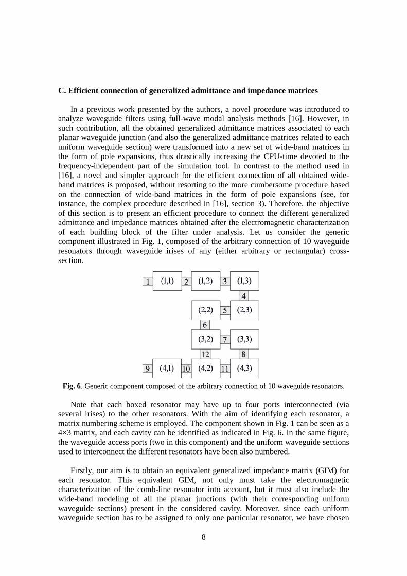
analyze waveguide filters using full-wave modal analysis methods [16]. However, in such contribution, all the obtained generalized admittance matrices associated to each planar waveguide junction (and also the generalized admittance matrices related to each uniform waveguide section) were transformed into a new set of wide-band matrices in the form of pole expansions, thus drastically increasing the CPU-time devoted to the frequency-independent part of the simulation tool. In contrast to the method used in [16], a novel and simpler approach for the efficient connection of all obtained wide-band matrices is proposed, without resorting to the more cumbersome procedure based on the connection of wide-band matrices in the form of pole expansions (see, for instance, the complex procedure described in [16], section 3). Therefore, the objective of this section is to present an efficient procedure to connect the different generalized admittance and impedance matrices obtained after the electromagnetic characterization of each building block of the filter under analysis. Let us consider the generic component illustrated in Fig. 1, composed of the arbitrary connection of 10 waveguide resonators through waveguide irises of any (either arbitrary or rectangular) cross-section.
Fig. 6. Generic component composed of the arbitrary connection of 10 waveguide resonators.
Note that each boxed resonator may have up to four ports interconnected (via several irises) to the other resonators. With the aim of identifying each resonator, a matrix numbering scheme is employed. The component shown in Fig. 1 can be seen as a 4×3 matrix, and each cavity can be identified as indicated in Fig. 6. In the same figure, the waveguide access ports (two in this component) and the uniform waveguide sections used to interconnect the different resonators have been also numbered.
Firstly, our aim is to obtain an equivalent generalized impedance matrix (GIM) for
each resonator. This equivalent GIM, not only must take the electromagnetic characterization of the comb-line resonator into account, but it must also include the wide-band modeling of all the planar junctions (with their corresponding uniform waveguide sections) present in the considered cavity. Moreover, since each uniform waveguide section has to be assigned to only one particular resonator, we have chosen
9
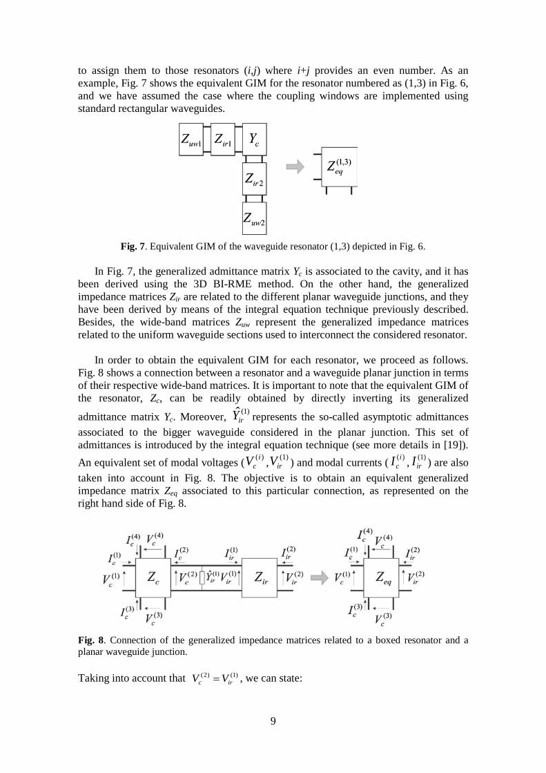
to assign them to those resonators (i,j) where i+j provides an even number. As an example, Fig. 7 shows the equivalent GIM for the resonator numbered as (1,3) in Fig. 6, and we have assumed the case where the coupling windows are implemented using standard rectangular waveguides.
Fig. 7. Equivalent GIM of the waveguide resonator (1,3) depicted in Fig. 6.
In Fig. 7, the generalized admittance matrix Yc is associated to the cavity, and it has
been derived using the 3D BI-RME method. On the other hand, the generalized impedance matrices Zir are related to the different planar waveguide junctions, and they have been derived by means of the integral equation technique previously described. Besides, the wide-band matrices Zuw represent the generalized impedance matrices related to the uniform waveguide sections used to interconnect the considered resonator.
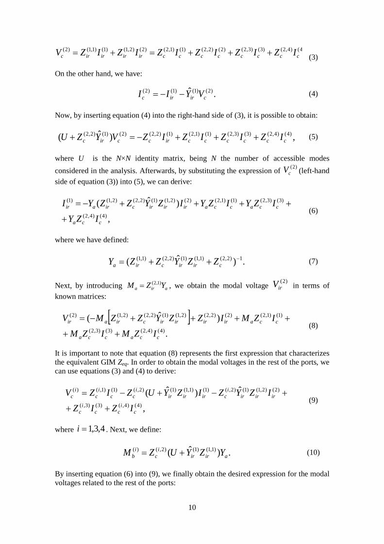
In order to obtain the equivalent GIM for each resonator, we proceed as follows.
Fig. 8 shows a connection between a resonator and a waveguide planar junction in terms of their respective wide-band matrices. It is important to note that the equivalent GIM of the resonator, Zc, can be readily obtained by directly inverting its generalized
admittance matrix Yc. Moreover, )1(irY represents the so-called asymptotic admittances
associated to the bigger waveguide considered in the planar junction. This set of admittances is introduced by the integral equation technique (see more details in [19]). An equivalent set of modal voltages ( )(i
cV , )1(irV ) and modal currents ( )(i
cI , )1(irI ) are also
taken into account in Fig. 8. The objective is to obtain an equivalent generalized impedance matrix Zeq associated to this particular connection, as represented on the right hand side of Fig. 8.
Fig. 8. Connection of the generalized impedance matrices related to a boxed resonator and a planar waveguide junction. Taking into account that )1()2(
irc VV = , we can state:
10
4()4,2()3()3,2()2()2,2()1()1,2()2()2,1()1()1,1()2(cccccccciriririrc IZIZIZIZIZIZV +++=+=
(3)
On the other hand, we have:
.ˆ )2()1()1()2(cirirc VYII −−= (4)
Now, by inserting equation (4) into the right-hand side of (3), it is possible to obtain:
,)ˆ( )4()4,2()3()3,2()1()1,2()1()2,2()2()1()2,2(ccccccirccirc IZIZIZIZVYZU +++−=+ (5)
where U is the N×N identity matrix, being N the number of accessible modes considered in the analysis. Afterwards, by substituting the expression of )2(
cV (left-hand side of equation (3)) into (5), we can derive:
,
)ˆ()4()4,2(
)3()3,2()1()1,2()2()2,1()1()2,2()2,1()1(
cca
ccaccairirircirair
IZYIZYIZYIZYZZYI
+
++++−= (6)
where we have defined:
.)ˆ( 1)2,2()1,1()1()2,2()1,1( −++= cirircira ZZYZZY (7)
Next, by introducing aira YZM )1,2(= , we obtain the modal voltage )2(
irV in terms of known matrices:
[ ].
)ˆ()4()4,2()3()3,2(
)1()1,2()2()2,2()2,1()1()2,2()2,1()2(
ccacca
ccairirirircirair
IZMIZMIZMIZZYZZMV
++
++++−= (8)
It is important to note that equation (8) represents the first expression that characterizes the equivalent GIM Zeq. In order to obtain the modal voltages in the rest of the ports, we can use equations (3) and (4) to derive:
,
ˆ)ˆ()4()4,()3()3,(
)2()2,1()1()2,()1()1,1()1()2,()1()1,()(
ci
cci
c
iririri
ciririri
cci
ci
c
IZIZIZYZIZYUZIZV
++
+−+−= (9)
where 4,3,1=i . Next, we define:
.)ˆ( )1,1()1()2,()(airir
ic
ib YZYUZM += (10)
By inserting equation (6) into (9), we finally obtain the desired expression for the modal voltages related to the rest of the ports:
11
[ ]
4,3,1 , )(
)()(
)ˆˆ(
)4()4,2()()4,(
)3()3,2()()3,()1()1,2()()1,(
)2()2,1()1()2,()2,1()1()2,2()2,1()()(
=−+
−+−+
−+=
icci
bi
c
cci
bi
ccci
bi
c
iririri
cirirciri
bi
c
IZMZIZMZIZMZ
IZYZZYZZMV
(11)
It is important to point up that this simple algorithm can be applied iteratively, as
many times as needed, to finally yield the desired equivalent GIM of the considered resonator. For instance, in the particular case depicted in Fig. 7, this procedure has to be applied four times to absorb the two matrices Zir related to the planar junctions, and the two matrices Zuw associated to the uniform waveguide sections. In the particular case where the matrix to absorb is related to a uniform waveguide section, note that the
asymptotic admittances )1(irY are no longer present in the formulation, and a very similar
algorithm can be easily found. Once each resonator has been characterized in terms of an equivalent generalized
impedance matrix, the obtained set of wide-band matrices must be properly connected to yield the electrical response of the analyzed component. To this aim, the inward modal electric currents present in the considered access ports and in the uniform waveguide sections can be selected as the unknowns of the problem. For example, in the particular case of the generic component depicted in Fig. 6, a system of linear equations with 12 unknowns (as many as the sum of the number of uniform waveguide sections and access ports) can be set up. Finally, the solution of this system of linear equations provides the scattering parameters of the whole device. III. RESULTS AND DISCUSSION
The accuracy of the implemented CAD tool has been validated through the analysis
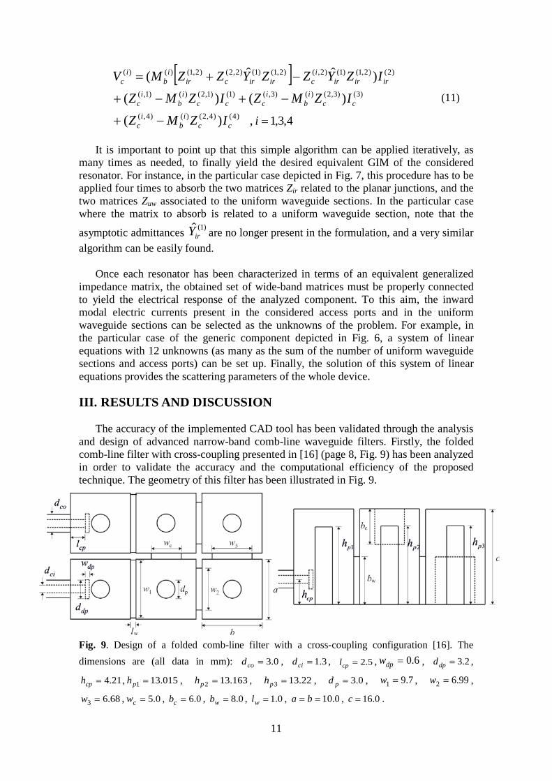
and design of advanced narrow-band comb-line waveguide filters. Firstly, the folded comb-line filter with cross-coupling presented in [16] (page 8, Fig. 9) has been analyzed in order to validate the accuracy and the computational efficiency of the proposed technique. The geometry of this filter has been illustrated in Fig. 9.
Fig. 9. Design of a folded comb-line filter with a cross-coupling configuration [16]. The dimensions are (all data in mm): 0.3=cod , 3.1=cid , 5.2=cpl , 6.0=dpw , 2.3=dpd ,
21.4=cph , 015.131 =ph , 163.132 =ph , 22.133 =ph , 0.3=pd , 7.91 =w , 99.62 =w ,
68.63 =w , 0.5=cw , 0.6=cb , 0.8=wb , 0.1=wl , 0.10== ba , 0.16=c .
12
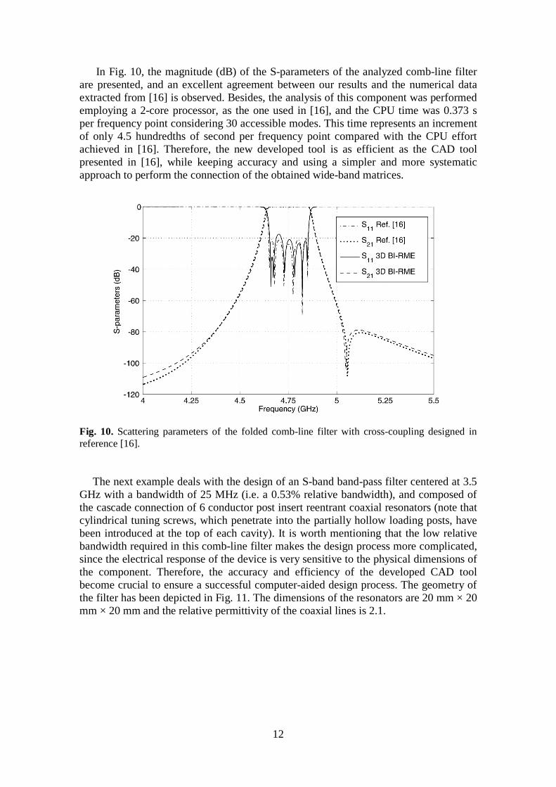
In Fig. 10, the magnitude (dB) of the S-parameters of the analyzed comb-line filter are presented, and an excellent agreement between our results and the numerical data extracted from [16] is observed. Besides, the analysis of this component was performed employing a 2-core processor, as the one used in [16], and the CPU time was 0.373 s per frequency point considering 30 accessible modes. This time represents an increment of only 4.5 hundredths of second per frequency point compared with the CPU effort achieved in [16]. Therefore, the new developed tool is as efficient as the CAD tool presented in [16], while keeping accuracy and using a simpler and more systematic approach to perform the connection of the obtained wide-band matrices.
Fig. 10. Scattering parameters of the folded comb-line filter with cross-coupling designed in reference [16].
The next example deals with the design of an S-band band-pass filter centered at 3.5
GHz with a bandwidth of 25 MHz (i.e. a 0.53% relative bandwidth), and composed of the cascade connection of 6 conductor post insert reentrant coaxial resonators (note that cylindrical tuning screws, which penetrate into the partially hollow loading posts, have been introduced at the top of each cavity). It is worth mentioning that the low relative bandwidth required in this comb-line filter makes the design process more complicated, since the electrical response of the device is very sensitive to the physical dimensions of the component. Therefore, the accuracy and efficiency of the developed CAD tool become crucial to ensure a successful computer-aided design process. The geometry of the filter has been depicted in Fig. 11. The dimensions of the resonators are 20 mm × 20 mm × 20 mm and the relative permittivity of the coaxial lines is 2.1.

13
Fig. 11. Design of a band-pass filter composed of conductor post insert reentrant coaxial resonators. The dimensions are (all data in mm): 2.4=cod , 27.1=cid , 817.3=pl ,
208.912 =w , 019.823 =w , 862.734 =w , 0.121 =pd , 0.102 =pd , 5.101 =ph , 0.32 =ph ,
344.121 =th , 509.122 =th , 533.123 =th , 0.3=td , 5.9=ch , 0.2=il , 0.8=ih . The scattering parameters of the designed filter have been represented in Fig. 12, and a very good agreement is observed between our simulated results and the numerical data provided by Ansys HFSS. The analysis of this band-pass filter was performed using 30 accessible modes, and it needed 12.45 s (2-core processor) per frequency point (Ansys HFSS needed about 160.4 s per frequency point to achieve convergent results in a 20-core processor).
Fig. 12. Scattering parameters of the S-band filter designed in Fig. 11. The last validation example addresses the design of an advanced L-band folded
comb-line filter with a cross-coupling configuration, as depicted in Fig. 13.
14
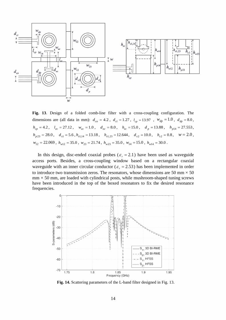
Fig. 13. Design of a folded comb-line filter with a cross-coupling configuration. The dimensions are (all data in mm): 2.4=cod , 27.1=cid , 97.13=cpl , 0.1=dpw , 0.8=dpd ,
2.4=cph , 12.27=ecl , 0.1=ecw , 0.8=ecd , 0.15=ech , 88.13=pd , 553.2714 =ph ,
0.2823 =ph , 6.51 =sd , 18.1314,1 =sh , 644.1223,1 =sh , 0.102 =sd , 8.02 =sh , 0.2=w ,
069.2212 =w , 0.3512 =wh , 74.2123 =w , 0.3523 =wh , 0.1514 =w , 0.3014 =wh . In this design, disc-ended coaxial probes ( 1.2=rε ) have been used as waveguide
access ports. Besides, a cross-coupling window based on a rectangular coaxial waveguide with an inner circular conductor ( 53.2=rε ) has been implemented in order to introduce two transmission zeros. The resonators, whose dimensions are 50 mm × 50 mm × 50 mm, are loaded with cylindrical posts, while mushroom-shaped tuning screws have been introduced in the top of the boxed resonators to fix the desired resonance frequencies.
Fig. 14. Scattering parameters of the L-band filter designed in Fig. 13.
15
The electrical response of the designed L-band band-pass filter (centre frequency of 1.85 GHz and a bandwidth of 20 MHz) has been represented in Fig. 14, where an excellent agreement is again observed between authors’ simulations and Ansys HFSS numerical data. Note that a sharp selectivity has been reached with this design due to the two transmission zeros provided by the electrical cross-coupling topology. In this case, the analysis of the filter needed 9 s per frequency point using a 6-core processor. The simulation with Ansys HFSS needed 18 s per frequency point in order to achieve convergent results, and it was performed in a more powerful workstation composed of 20 cores. It is worthy to mention that the increase of the simulation time devoted to the last two designed band-pass filters is mainly due to the complexity of such structures, which demands a very high density meshing of the resonators to properly represent the strong variation of the electromagnetic fields inside the considered components. Moreover, note that the required low relative bandwidths of the designed comb-line filters also have a strong influence on the sensitivity of the electrical performance of the filter, and this fact affects, as well, to the density of the applied meshing.
IV. CONCLUSION
A very flexible CAD tool specially suited for the full-wave analysis and design of advanced comb-line waveguide filters has been presented. The proposed simulation tool is able to cope with the electromagnetic characterization of generalized radially symmetrical posts, thus allowing for the efficient and accurate analysis of a great variety of practical microwave filters, such as those based on conductor post insert reentrant coaxial resonators. The developed CAD tool is able to deal, as well, with coupling windows of arbitrary cross-section (in order to consider disc-ended electrical probes), hence enhancing the flexibility of the design process. The full-wave analysis of the investigated microwave filters is performed by combining an integral equation technique for characterizing the planar waveguide junctions present in the analyzed component, and the Boundary Integral – Resonant Mode Expansion technique (2D and 3D versions). Moreover, a novel and simple procedure to efficiently connect the obtained wide-band generalized matrices has been proposed. The accuracy of the developed CAD tool has been successfully validated through several designs of advanced comb-line rectangular waveguide filters (some of them with very narrow passbands).
Acknowledgments
This work has been supported by the Ministerio de Economía y Competitividad, Spanish Government, under the Research Projects TEC2013-47037-C5-1-R and TEC2013-47037-C5-4-R, as well as by the FP7 PCIG11-2012-322162 Marie Curie CIG grant.
16
REFERENCES
[1] J. Uher, J. Bornemann, and U. Rosenberg, Waveguide components for antenna feed systems: theory and CAD, Artech House, Norwood, 1993.
[2] V. E. Boria and B. Gimeno, Waveguide filters for satellites, IEEE Microwave Magazine 8, no. 5 (2007) , 60–70
[3] K. Shamsaifar, T. Rodriguez, and J. Haas, High-power combline diplexer for space,
IEEE Transactions on Microwave Theory and Techniques 61, no. 5 (2013), 1850–1860.
[4] C. Wang, K. A. Zaki, A. E. Atia, and T. G. Dolan, Dielectric combline resonators and filters, IEEE Transactions on Microwave Theory and Techniques 46, no. 12 (1998), 2501–2506.
[5] K. Wu, R. R. Mansour, and H. Wang, A full wave analysis of a conductor post insert reentrant coaxial resonator in rectangular waveguide combline filters, 1996 IEEE MTT-S International Microwave Symposium Digest, pp. 1639-1642.
[6] R. Levy and J. D. Rhodes, A comb-line elliptic filter, IEEE Transactions on Microwave Theory and Techniques 19 (1971), 26–29.
[7] G. L. Matthaei, Comb-line band-pass filters of narrow or moderate bandwidth, Microwave Journal 6 (1963), 82–91.
[8] M. El Sabbagh, K. A. Zaki, H. Yao, and M. Yu, Full-wave analysis of coupling between combline resonators and its application to combline filters with canonical configurations, IEEE Transactions on Microwave Theory and Techniques 49, no. 12 (2001), 2384–2393.
[9] H. Yao, K. A. Zaki, A. E. Atia, and R. Hershtig, Full-wave modeling of conducting posts in rectangular waveguides and its applications to slot coupled combline filters, IEEE Transactions on Microwave Theory and Techniques 43, no. 12 (1995), 2824–2830.
[10] A. V. G. Subramanyam, D. Sivareddy, V. V. Srinivasan, and V. K. Hariharan, Multipaction-free combline diplexer for deep space applications, 2014 IEEE International Microwave and RF Conference, pp. 217–220.
[11] A. Morini, G. Venanzoni, M. Farina, and T. Rozzi, Modified adaptive prototype inclusive of the external couplings for the design of coaxial filters, IEEE Transactions on Microwave Theory and Techniques 55, no. 9 (2007), 1905–1911.
[12] A. Morini, G. Venanzoni, and T. Rozzi, A new adaptive prototype for the design of side-coupled coaxial filters with close correspondence to the physical structure, IEEE Transactions on Microwave Theory and Techniques 54, no. 3 (2006), 1146–1153.
[13] X. Shang, Y. Wang, W. Xia, and M. J. Lancaster, Novel multiplexer topologies based on all-resonator structures, IEEE Transactions on Microwave Theory and Techniques 61, no. 11 (2013), 3838–3845.
[14] Y. Wang and M. J. Lancaster, An investigation on the coupling characteristics of a novel multiplexer configuration, Proceedings of the 2013 European Microwave Conference, pp. 900–903.
[15] P. Arcioni, M. Bozzi, M. Bressan, G. Conciauro, and L. Perregrini, Frequency/time domain modeling of 3D waveguide structures by a BI-RME approach, International Journal of Numerical Modelling: Electronic Networks, Devices and Fields 15 (2002), 3–21.
[16] F. Mira, A. A. San Blas, V. E. Boria, L. J. Roglá, and B. Gimeno, Wideband generalized admittance matrix representation for the analysis and design of waveguide filters with coaxial excitation, Radio Science 48, no. 11 (2013), 1–11.
17
[17] M. Bressan, F. Mira, G. Conciauro, V. E. Boria, and B. Gimeno, S-domain modeling of conducting post in rectangular waveguides by the BI-RME method, Proceedings of the 2002 European Microwave Conference, pp. 1–4.
[18] F. Mira, M. Bressan, G. Conciauro, B. Gimeno, and V. E. Boria, Fast S-domain modeling of rectangular waveguides with radially symmetric metal insets, IEEE Transactions on Microwave Theory and Techniques 53, no. 4 (2005), 1294–1303.
[19] G. Gerini, M. Guglielmi, and G. Lastoria, Efficient integral equation formulations for the computation of the multimode admittance or impedance matrix of planar waveguide junctions, 1998 IEEE MTT-S International Microwave Symposium Digest 3, pp. 1747–1750.
[20] G. Conciauro, M. Bressan, and C. Zuffada, Waveguide modes via an integral equation leading to a linear matrix eigenvalue problem, IEEE Transactions on Microwave Theory and Techniques 32, no. 11 (1984), 1495–1504.
[21] S. Cogollos, S. Marini, V. E. Boria, P. Soto, A. Vidal, H. Esteban, J. V. Morro, and B. Gimeno, Efficient modal analysis of arbitrarily shaped waveguides composed of linear, circular, and elliptical arcs using the BI-RME method, IEEE Transactions on Microwave Theory and Techniques 51, no. 12 (2003), 2378–2390.
18
BIOGRAPHIES
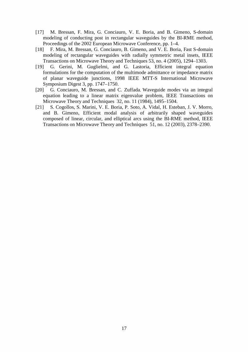
Ángel A. San Blas was born in Valencia, Spain, in 1976. He received the Ingeniero de Telecomunicación degree and the Doctor Ingeniero de Telecomunicación degree from the Universidad Politécnica de Valencia, Valencia, Spain, in 2000 and 2008, respectively. In 2001, he became a Researcher with the Departamento de Comunicaciones, Universidad Politécnica de Valencia, where he was involved in the development of simulation tools for the analysis and design of
waveguide devices. From November 2001 to March 2002, he was a Researcher at Dipartimento di Elettronica, Università degli Studi di Pavia, Pavia (Italy), in the framework of the European Network MMCODEF (Millimetre-wave and Microwave Components Design Framework for Ground and Space Multimedia Network, V European Framework Programme). Since 2003, he has been an Associate Professor with the Departamento de Ingeniería de Comunicaciones, Universidad Miguel Hernández de Elche, Elche (Spain). His current research interests include numerical methods for the efficient analysis and design of passive and active waveguide components.
Ana Vidal was born in Valencia, Spain, in 1970. She received the Telecommunication Engineering degree and the Doctor Ingeniero de Telecomunicación degree from the Universidad Politécnica de Valencia, Valencia, Spain, in 1993 and 2013, respectively. She spent one year with the University of Strathclyde, Glasgow, U.K., in 1993 under an international exchange program. She was also a Trainee involved in broadband communications development in the main
research center of Telecom Portugal in Aveiro, Portugal. She joined the European Space Agency for two years as a Research Trainee, where her main activity was the study and implementation of software for synthetic aperture radar (SAR) image processing. In 1996, she returned to the Universidad Politécnica de Valencia, where she held several lecturing positions. Since 2001, she has been an Associate Professor with the Universidad Politécnica de Valencia. Her current interests are SAR data processing, Remote Sensing classification for Earth Observation, and numerical method development for the analysis of microwave structures.
Andrei A. Muller was born in Bucharest (Romania). He received a M.S degree in Mobile Communications and a Ph.D. degree in Microwave Engineering from the Polytechnic University of Bucharest (2011). Andrei performed a Post Doc in Brest (France) with the Lab-STIC Group (2012) in the frame of SIW filter design. Since 2013 he started the work in the Microwave Applications Group, Telecommunications Institute of Valencia – iTeam (Spain) obtaining
a Marie Curie Integration Grant from the European Commission. Andrei received the Gheorghe Cartianu prize of the Romanian Academy (December 2013) for the articles on the 3D Smith chart concept, which he presented in invited talks in United Kingdom, Germany and Spain. Throughout his career he spent 7 months (2010) in the Pure and Applied Mathematics Institute of Valencia (Spain), 3 months (2009) in the CEFIM Institute (South Africa) working on antenna design, and 18 months (2007) in HFT Munich (Germany), working on rearrangeable switching networks design.
19
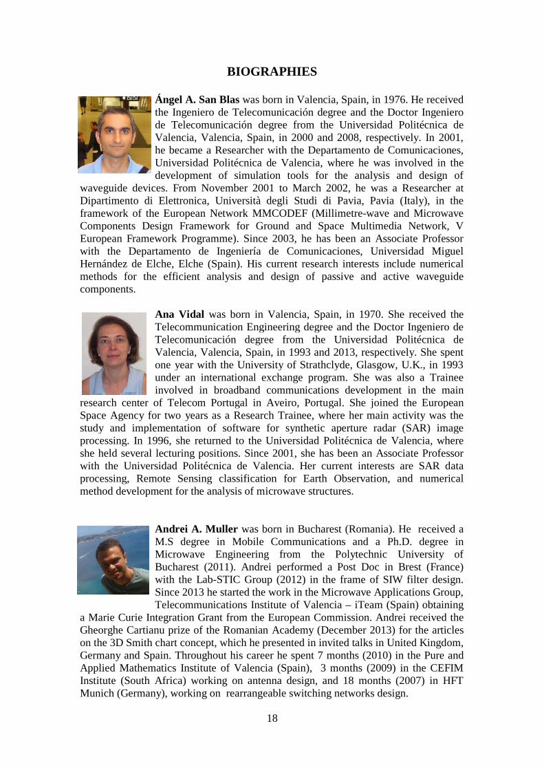
Pablo Soto was born in 1975 in Cartagena, Spain. He received the M.S. degree and Ph.D. degree (cum Laude) in Telecommunication Engineering from the Universidad Politécnica de Valencia in 1999 and 2012, respectively. In 2000 he joined the Departamento de Comunicaciones, Universidad Politécnica de Valencia, where he is Associate Professor since 2012. In 2000 he was a fellow with the European Space Research and Technology Centre (ESTEC-ESA),
Noordwijk, the Netherlands. His research interests comprise numerical methods for the analysis, synthesis and automated design of passive components in waveguide and planar technologies, as well as the development and design of novel hardware for satellite applications. Dr. Soto received the 2000 and 2012 COIT/AEIT national award to the best Master Thesis and best Ph. D. Thesis, respectively. He serves as reviewer of IEEE Transactions on Microwave Theory and Techniques and IEEE Microwave and Wireless Component Letters.
Fermín Mira received the Telecommunications Engineering degree and the PhD degree in Telecommunications from the Technical University of Valencia in 2000 and 2005, respectively. In 2001, he joined the Department of Electronics, Università degli Studi di Pavia, Italy, where he was a Pre-Doctoral Fellow (2001-2004) involved with a research project financed by the European Community under the framework of a Marie Curie Action of the 5th Program Marco
"Millimeter-Wave and Microwave Components Design Framework for Ground and Space Multimedia Network (MMCODEF)", aimed at the development of a CAD tools for the design passive microwave components and with the participation of the European Space Agency. In May 2004, he joined the Department of Communications, Universidad Politécnica de Valencia, working toward his PhD degree. In January 2006 he joined the CTTC as researcher in the division of Communication Technologies. He has published 25 works, including book chapters, journals and international conferences. His current research interests include numerical methods for electromagnetic modelling of microwave and millimeter-wave components, and design of waveguide and planar filters, especially substrate integrated circuits (SIC).
Francisco Javier Pérez Soler was born in Murcia, Spain. In 2004, he received the degree in Electrical Engineering at the Technical University of Cartagena. He joined there the Group of Electromagnetics Applied to Telecommunications for 4 years, while he developed his Ph. D. in numerical methods for electromagnetics. Currently, he works as software developer of fast numerical methods for analysis of microwave devices in Aurora Software and Testing S.L.
20
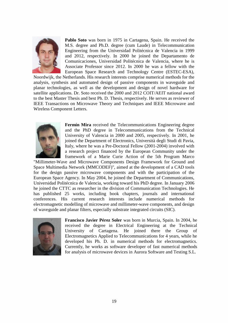
Benito Gimeno was born in Valencia, Spain, on January 29, 1964. He received the Licenciado degree in Physics in 1987 and the PhD degree in 1992, both from the Universidad de Valencia, Spain. He was a Fellow at the Universidad de Valencia from 1987 to 1990. Since 1990 he served as Assistant Professor in the Departamento de Física Aplicada y Electromagnetismo and ICMUV (Instituto de Ciencia de Materiales) at the Universidad de Valencia, where he
became Associate Professor in 1997 and Full Professor in 2010. He was working at ESA/ESTEC (European Space Research and Technology Centre of the European Space Agency) as a Research Fellow during 1994 and 1995. In 2003 he obtained a Fellowship from the Spanish Government for a short stay at the Università degli Studi di Pavia (Italy) as a Visiting Scientific. His current research interests include the areas of computer-aided techniques for analysis of microwave and millimetre-wave passive components for space applications, waveguides and cavities structures including dielectric objects, electromagnetic band-gap structures, frequency selective surfaces, and non-linear phenomena appearing in power microwave subsystems and particle accelerators (multipactor effect, corona effect and passive inter-modulation phenomena).
Vicente E. Boria was born in Valencia, Spain, on May 18, 1970. He received his “Ingeniero de Telecomunicación” degree (with first-class honors) and the “Doctor Ingeniero de Telecomunicación” degree from the Universidad Politécnica de Valencia, Valencia, Spain, in 1993 and 1997, respectively. In 1993 he joined the “Departamento de Comunicaciones”, Universidad Politécnica de Valencia, where he has
been Full Professor since 2003. He has authored or co-authored 7 chapters in technical textbooks, 75 papers in refereed international technical journals, and over 150 papers in international conference proceedings. His current research interests are focused on the analysis and automated design of passive components, left-handed and periodic structures, as well as on the simulation and measurement of power effects in passive waveguide systems. Dr. Boria is member of the Editorial Boards of the IEEE Transactions on Microwave Theory and Techniques, IEEE Microwave and Wireless Components Letters, Proceeding of the IET (Microwaves, Antennas and Propagation), IET Electronics Letters and Radio Science. Since 2013, he serves as Associate Editor of IEEE Microwave and Wireless Components Letters. He is also a member of the Technical Committees of the IEEE-MTT International Microwave Symposium and of the European Microwave Conference.