flex-vey · understand the potential danger of someone getting too close or trying to make repairs...
TRANSCRIPT
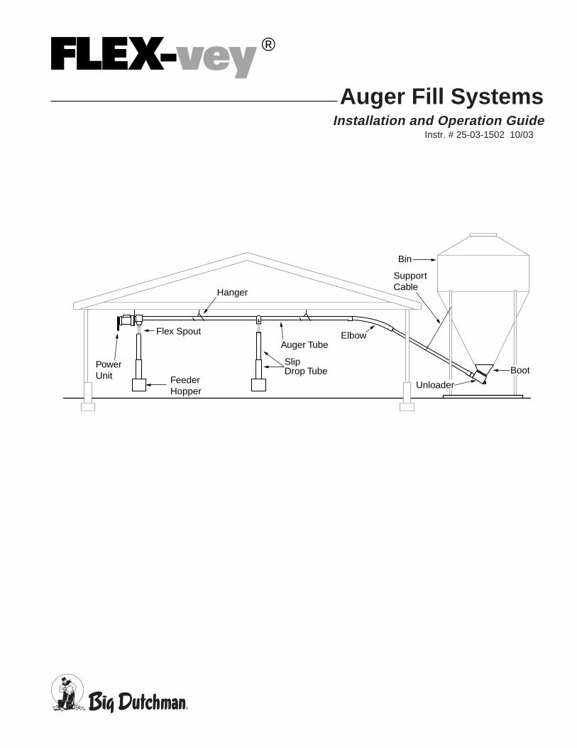
Auger Fill SystemsInstallation and Operation Guide
Instr. # 25-03-1502 10/03
PowerUnit
Flex Spout
SlipDrop Tube
Auger TubeElbow
Hanger
Bin
SupportCable
FeederHopper
Boot
Unloader
FLEX-vey ®
2 Instr. # 25-03-1502 10/03
MAKE SURE ALL PERSONNELUNDERSTAND THE POTENTIAL DANGERof someone getting too close or trying to makerepairs or adjustments while the machine isrunning. This equipment has several AREASWHERE INJURIES COULD OCCUR.
KEEP ALL COVERS AND GUARDS INPLACE WHILE EQUIPMENT IS INOPERATION.
Observe the following precautions whenservicing the Flex-vey Fill System:• Do not remove guards except when
performing maintenance.• Do not operate the machine when guards or
covers are removed.• When performing maintenance or repairs
make sure the local control switch is OFFand the main power control panel is OFFand tagged "DO NOT OPERATE."
• Make all adjustments with the power OFF.• NEVER reach into the machine while the
system is operating. Keep hands out of themachine and belt or auger areas. Keep allguards and covers in place when power ison.
• Work carefully and give the work you aredoing your undivided attention. Do not lookaway, talk or play around. Careless acts cancause SERIOUS INJURY.
Warnings, Cautions and Notes
This manual contains Warnings,Cautions, and Notes in addition to theassembly and operating instructions. Thesecomments offer helpful hints to aid in assemblyof the Flex-vey Fill System and alerts to warnof situations where the possibility of personalinjury exists.
Please take the time to read andunderstand this manual before beginningassembly.
CAREFULLY FOLLOW THE SAFETYAND START-UP OPERATINGINSTRUCTIONS in this manual.
Observe the following precautions whenworking on or near the Flex-vey Fill System:• Understand the limitations and hazards
associated with operating this equipmentbefore using.
• Wear appropriate eye protection whenassembling and operating this equipment
• Do not wear loose clothing, jewelry, etc.• Keep sleeves rolled above the elbows.• Confine long hair.• Always wear approved protective footwear.
Instr. # 25-03-1502 10/03 3
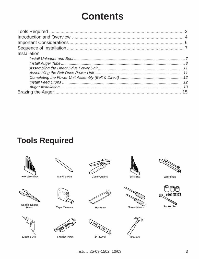
Tools Required
Hex Wrenches Cable Cutters Drill Bits
Electric Drill
Hacksaw
Hammer24" Level
Marking Pen Wrenches
Needle NosedPliers Screwdrivers Socket SetTape Measure
Locking Pliers
ContentsTools Required .......................................................................................................... 3Introduction and Overview ........................................................................................ 4Important Considerations .......................................................................................... 6Sequence of Installation ............................................................................................ 7Installation
Install Unloader and Boot ...................................................................................................... 7Install Auger Tube .................................................................................................................. 8Assembling the Direct Drive Power Unit .............................................................................. 11Assembling the Belt Drive Power Unit ................................................................................. 11Completing the Power Unit Assembly (Belt & Direct) .......................................................... 12Install Feed Drops ............................................................................................................... 12Auger Installation ................................................................................................................. 13
Brazing the Auger.................................................................................................... 15

4 Instr. # 25-03-1502 10/03
Introduction andOverview
Direct Drive Belt Drive
PowerUnit
Flex Spout
SlipDrop Tube
Auger TubeElbow
Hanger
Bin
SupportCable
FeederHopper
Boot
Unloader
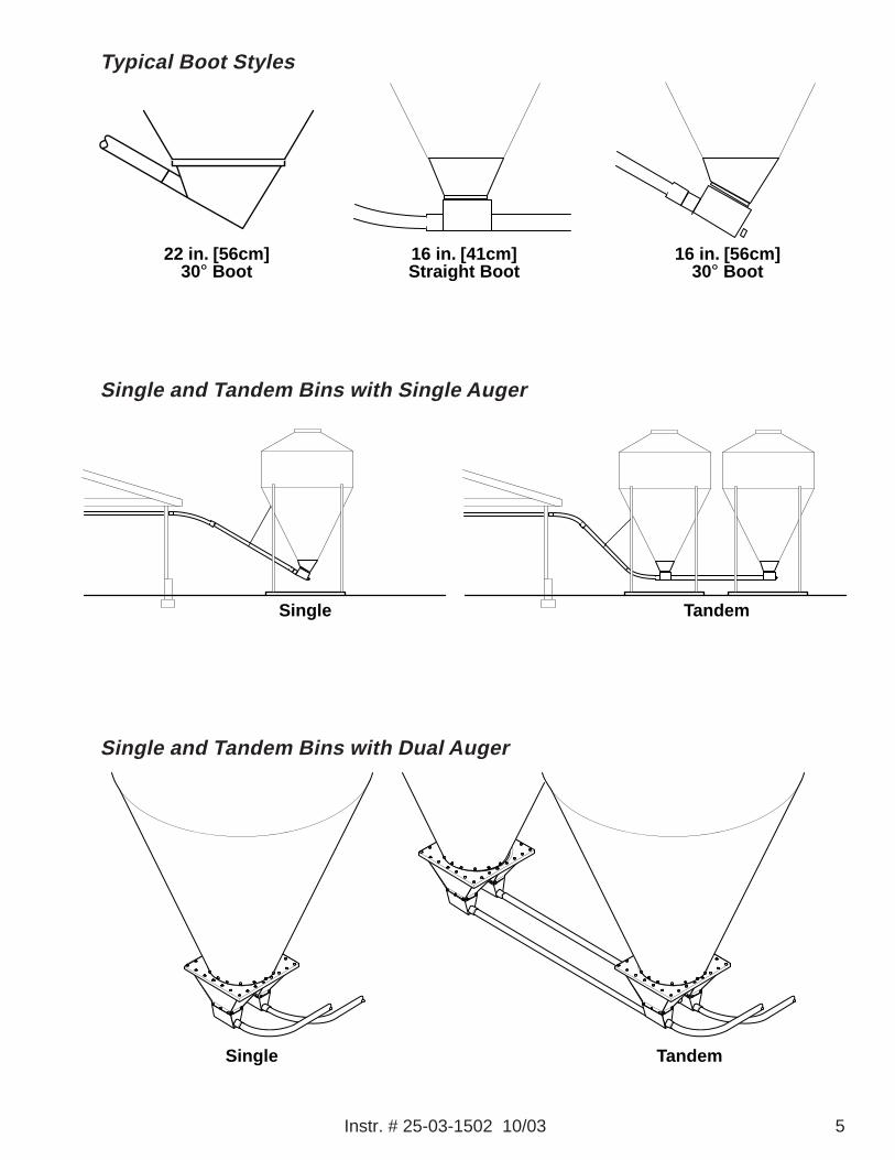
The Flex-vey Fill System includeseverything between the Bin and the FeedHopper(s). Starting at the Bin, a Boot isattached at the bottom of the bin. There isusually an Unloader valve installed on thisboot, but in the case of the 22 inch opening bin,the boot is also the unloader.
The Auger and Auger Tube begin at theunloader. If the unloader is level with theground, an Elbow is installed at the unloader.Usually the unloader is mounted to a boot at a30 degree angle, so an elbow is not needed.The auger tube then rises into the building.
Depending on the placement of the bin,the next elbow is either inside or outside of thebuilding. This elbow brings the auger tube leveland near the ceiling of the building.
The auger tube is suspended near theceiling and continues toward the first feedhopper. A Drop is installed at the feed hopper.A short length of flexible tube is installed at thedrop. A Coupler is used if the auger tubeneeds to be joined and there is no belled endavailable.
It is important to plan ahead. Please read this entire manual before you begin the actualassembly and installation. Taking the time to read all of the instructions may help you avoid costlyerrors during the assembly and installation process.
This manual covers general installation of all Flex-vey fill systems offered by Big Dutchman. Inan attempt to make this manual work for all systems, drawings were chosen to be the mostinformative. The system you are installing may look slightly different than the illustrations in thismanual. Refer to the Parts Book furnished with the equipment for the actual parts in your system.
Power Units
The drop at the last feed hopper is part ofthe Power Unit. The power units may be belt ordirect drive. Flex-vey fill systems are availablein several diameters. You may have any of thefollowing configurations:
• Single Auger, Single Bin• Single Auger, Tandem Bins• Dual Augers, Single Bin• Dual Augers, Tandem BinsThe fill system may be supplying feed to
two hoppers in a broiler house or as many astwenty five hoppers in a large layer house. Allsystems share similar parts with the samefunctions.
Typical Installation
Instr. # 25-03-1502 10/03 5
TandemSingle
Single Tandem
16 in. [41cm]Straight Boot
22 in. [56cm]30° Boot
16 in. [56cm]30° Boot
Typical Boot Styles
Single and Tandem Bins with Single Auger
Single and Tandem Bins with Dual Auger

6 Instr. # 25-03-1502 10/03
CL
45 ° ELBOW
30° ELBOW
A
BC
EACH SQUARE EQUALS 1 ft. [304.8mm]CL
3-1/8 in. [80mm] Direct-Drive6-5/8 in. [169mm] Belt-Drive
Minimum Distance from Ceiling
NOTE: All measurements assumeBin Pad and House Floor are samelevel and 8 ft. [2.44m] ceiling.
30° Rise –6 15/16 in. [176.2mm]Vertical for every 12 in. [304.8mm] Horizontal
45° Rise –12 in. [304.8mm] Vertical for every 12 in. [304.8mm] Horizontal
16 in. [41cm] Boots
PLACEMENT CHART
Bins
Common Measurement fromBottom Bin to Pad
Length from Center of Binto Wall (45° Rise)
Length from Center of Binto Wall (30° Rise)
6 ft. [1.8m]
32 7/8 in[.835m]
9 ft.- 7 in.[2.95m]
13 ft.- 9 in.[4.24m]
7 ft. [2.1m]
36 1/2 in.[.927m]
9 ft.- 5 in.[2.89m]
13 ft.- 5 in.[4.11m]
9 ft. [2.7m]
32 5/8 in.[.830m]
9 ft.- 7 in.[2.95m]
13 ft.- 9 in.[4.24m]
12 ft. [3.7m]
35 3/4 in.[.908m]
9 ft.- 5 in.[2.89m]
13 ft.- 5 in.[4.11m]
A
B
C
22 in. [56cm] Boots
Bins
Common Measurement fromBottom Bin to Pad
Length from Center of Binto Wall (45° Rise)
Length from Center of Binto Wall (30° Rise)
6 ft. [1.8m]
32 7/8 in.[.835m]
8 ft.-10 1/2 in.[2.705m]
12 ft.[3.658m]
7 ft. [2.1m]
36 1/2 in.[.927m]
8 ft.- 8 1/2 in.[2.654m]
11 ft.- 8 9/32in.[3.563m]
9 ft. [2.7m]
32 5/8 in.[.830m]
8 ft.-10 1/2 in.[2.705m]
12 ft.[3.658m]
12 ft. [3.7m]
35 3/4 in.[.908m]
8ft.- 8 27/32in.[2.663m]
11 ft.- 8 3/8 in.[3.566m]
A
B
C
Important ConsiderationsDistance between the bin and the building
When locating the concrete foundation forthe bin, the location of the first feed dropand the height at which the tube will enterthe building must be considered.
Position of feed drop tubesThe drop locations should be determinedaccurately.
Amount of overhead clearance requiredinside the building
The minimum clearance to the top of thetube must be 3 1/8 in. [80mm] when using adirect drive power unit or 6 5/8 in. [169mm]when using a belt drive power unit.
IMPORTANT: When considering overheadclearance, remember some modelsof power units require access to thetop of the switch housing forattaching auger.
Instr. # 25-03-1502 10/03 7
Sequence of Installation
Boot
22 in. Boot
Feed Shut-offSlide Adapter KitBoot Adapter
Slide ShieldAssembly
Plastic Boot
16 in. Boot and Unloader
Installation
Install Unloader and Boot
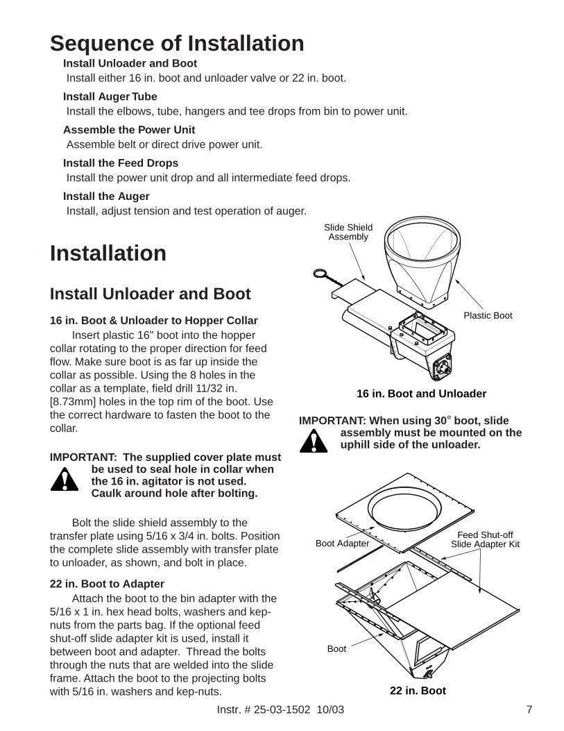
16 in. Boot & Unloader to Hopper CollarInsert plastic 16" boot into the hopper
collar rotating to the proper direction for feedflow. Make sure boot is as far up inside thecollar as possible. Using the 8 holes in thecollar as a template, field drill 11/32 in.[8.73mm] holes in the top rim of the boot. Usethe correct hardware to fasten the boot to thecollar.
IMPORTANT: The supplied cover plate mustbe used to seal hole in collar whenthe 16 in. agitator is not used.Caulk around hole after bolting.
Bolt the slide shield assembly to thetransfer plate using 5/16 x 3/4 in. bolts. Positionthe complete slide assembly with transfer plateto unloader, as shown, and bolt in place.
22 in. Boot to AdapterAttach the boot to the bin adapter with the
5/16 x 1 in. hex head bolts, washers and kep-nuts from the parts bag. If the optional feedshut-off slide adapter kit is used, install itbetween boot and adapter. Thread the boltsthrough the nuts that are welded into the slideframe. Attach the boot to the projecting boltswith 5/16 in. washers and kep-nuts.
Install Unloader and BootInstall either 16 in. boot and unloader valve or 22 in. boot.
Install Auger TubeInstall the elbows, tube, hangers and tee drops from bin to power unit.
Assemble the Power UnitAssemble belt or direct drive power unit.
Install the Feed DropsInstall the power unit drop and all intermediate feed drops.
Install the AugerInstall, adjust tension and test operation of auger.
IMPORTANT: When using 30° boot, slideassembly must be mounted on theuphill side of the unloader.

8 Instr. # 25-03-1502 10/03
Install Auger Tube1. Locate the point at which the tube will enter
the building. This is done by marking avertical chalk line on the outside wall of thebuilding directly opposite the bin spout. Theheight of the hole is found by running astring from the top of the spout to the wall atthe angle of the auger tube if the elbow is tobe inside the building. When the elbow is tobe outside the building, the hole is locatedat the height of the auger tube inside thebuilding.
IMPORTANT: Remember to allow roomunder the ceiling for the power unit.If there is no ceiling, the tube mayenter directly under the eaves orthrough the top face board.
Elbow(Outside)
Elbow(Inside)
MinimumDistance
MinimumDistance
Location of Elbow
Neoprene Seal
Sealing Plate
Weather Seal Kit
2. Cut a hole large enough to pass the augertube through the sidewall of the building.Install weather seal kit over this opening.
3. Push the belled end of the first section oftube over the boot spout. Secure the tube tothe boot spout with the clamp provided.
Instr. # 25-03-1502 10/03 9
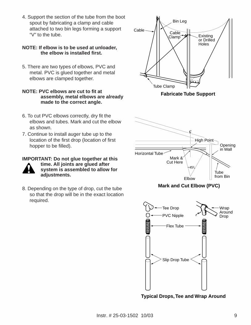
4. Support the section of the tube from the bootspout by fabricating a clamp and cableattached to two bin legs forming a support“V” to the tube.
NOTE: If elbow is to be used at unloader,the elbow is installed first.
5. There are two types of elbows, PVC andmetal. PVC is glued together and metalelbows are clamped together.
NOTE: PVC elbows are cut to fit atassembly, metal elbows are alreadymade to the correct angle.
6. To cut PVC elbows correctly, dry fit theelbows and tubes. Mark and cut the elbowas shown.
7. Continue to install auger tube up to thelocation of the first drop (location of firsthopper to be filled).
IMPORTANT: Do not glue together at thistime. All joints are glued aftersystem is assembled to allow foradjustments.
8. Depending on the type of drop, cut the tubeso that the drop will be in the exact locationrequired.
Elbow
Horizontal Tube
Openingin Wall
Tubefrom Bin
45°
Mark &Cut Here
High Point
CL
Mark and Cut Elbow (PVC)
Cable
Bin Leg
CableClamp
Tube Clamp
Existingor DrilledHoles
Fabricate Tube Support
Flex Tube
Tee Drop WrapAroundDropPVC Nipple
Slip Drop Tube
Typical Drops, Tee and Wrap Around
10 Instr. # 25-03-1502 10/03
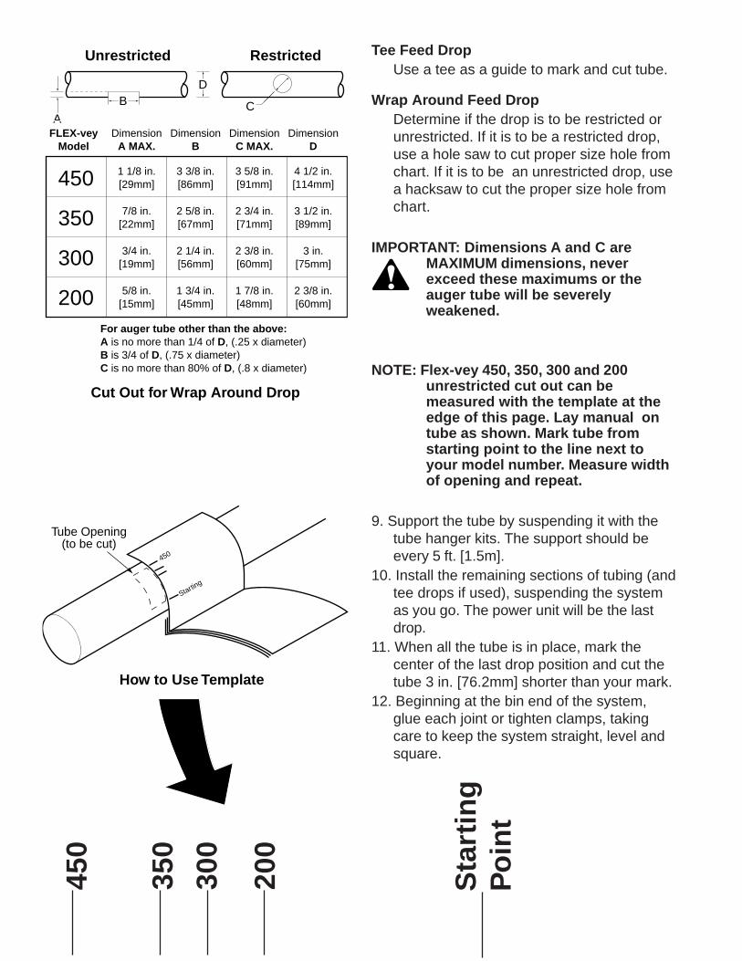
Tee Feed DropUse a tee as a guide to mark and cut tube.
Wrap Around Feed DropDetermine if the drop is to be restricted orunrestricted. If it is to be a restricted drop,use a hole saw to cut proper size hole fromchart. If it is to be an unrestricted drop, usea hacksaw to cut the proper size hole fromchart.
IMPORTANT: Dimensions A and C areMAXIMUM dimensions, neverexceed these maximums or theauger tube will be severelyweakened.
NOTE: Flex-vey 450, 350, 300 and 200unrestricted cut out can bemeasured with the template at theedge of this page. Lay manual ontube as shown. Mark tube fromstarting point to the line next toyour model number. Measure widthof opening and repeat.
9. Support the tube by suspending it with thetube hanger kits. The support should beevery 5 ft. [1.5m].
10. Install the remaining sections of tubing (andtee drops if used), suspending the systemas you go. The power unit will be the lastdrop.
11. When all the tube is in place, mark thecenter of the last drop position and cut thetube 3 in. [76.2mm] shorter than your mark.
12. Beginning at the bin end of the system,glue each joint or tighten clamps, takingcare to keep the system straight, level andsquare.
ACB
D
RestrictedUnrestricted
FLEX-veyModel
DimensionA MAX.
DimensionB
DimensionC MAX.
DimensionD
1 1/8 in.[29mm]
3 3/8 in.[86mm]
3 5/8 in.[91mm]
4 1/2 in.[114mm]
7/8 in.[22mm]
2 5/8 in.[67mm]
2 3/4 in.[71mm]
3 1/2 in.[89mm]
3/4 in.[19mm]
2 1/4 in.[56mm]
2 3/8 in.[60mm]
3 in.[75mm]
5/8 in.[15mm]
1 3/4 in.[45mm]
1 7/8 in.[48mm]
2 3/8 in.[60mm]
450
350
300
200For auger tube other than the above:A is no more than 1/4 of D, (.25 x diameter)B is 3/4 of D, (.75 x diameter)C is no more than 80% of D, (.8 x diameter)
Cut Out for Wrap Around Drop
450
350
300
200
Sta
rtin
gP
oin
tTube Opening
(to be cut)
Manual
450
Starting
How to Use Template
Instr. # 25-03-1502 10/03 11
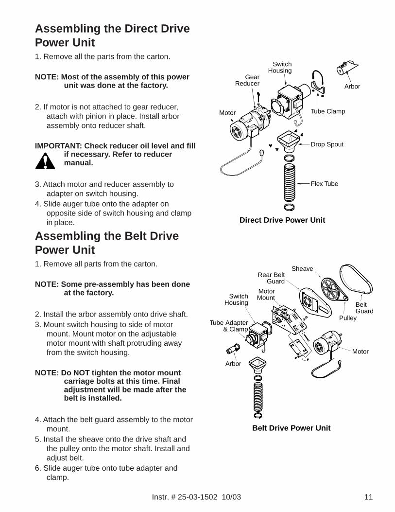
Assembling the Direct DrivePower Unit1. Remove all the parts from the carton.
NOTE: Most of the assembly of this powerunit was done at the factory.
2. If motor is not attached to gear reducer,attach with pinion in place. Install arborassembly onto reducer shaft.
IMPORTANT: Check reducer oil level and fillif necessary. Refer to reducermanual.
3. Attach motor and reducer assembly toadapter on switch housing.
4. Slide auger tube onto the adapter onopposite side of switch housing and clampin place.
Assembling the Belt DrivePower Unit1. Remove all parts from the carton.
NOTE: Some pre-assembly has been doneat the factory.
2. Install the arbor assembly onto drive shaft.3. Mount switch housing to side of motor
mount. Mount motor on the adjustablemotor mount with shaft protruding awayfrom the switch housing.
NOTE: Do NOT tighten the motor mountcarriage bolts at this time. Finaladjustment will be made after thebelt is installed.
4. Attach the belt guard assembly to the motormount.
5. Install the sheave onto the drive shaft andthe pulley onto the motor shaft. Install andadjust belt.
6. Slide auger tube onto tube adapter andclamp.
Drop Spout
Flex Tube
Arbor
Tube Clamp
SwitchHousing
GearReducer
Motor
Direct Drive Power Unit
SwitchHousing
Tube Adapter& Clamp
Arbor
MotorMount
BeltGuard
Pulley
Rear BeltGuard
Sheave
Motor
Belt Drive Power Unit
12 Instr. # 25-03-1502 10/03
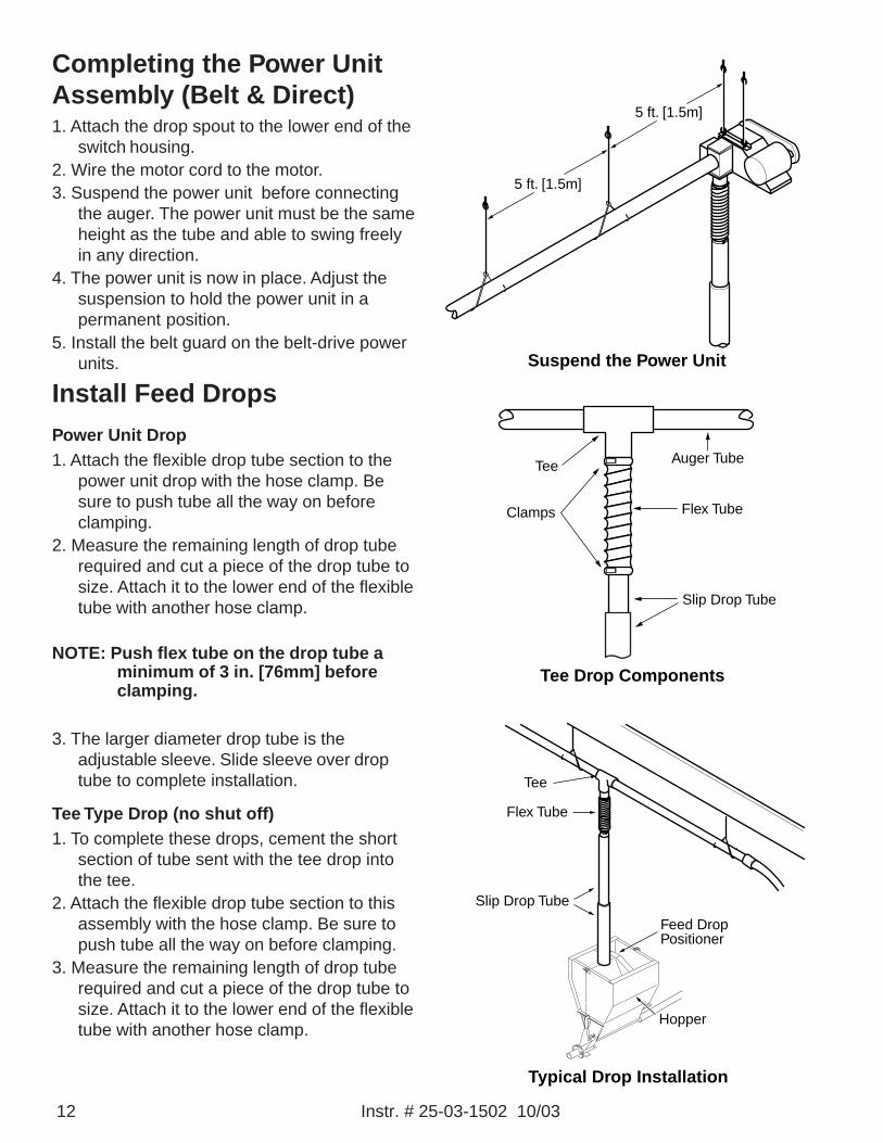
Completing the Power UnitAssembly (Belt & Direct)1. Attach the drop spout to the lower end of the
switch housing.2. Wire the motor cord to the motor.3. Suspend the power unit before connecting
the auger. The power unit must be the sameheight as the tube and able to swing freelyin any direction.
4. The power unit is now in place. Adjust thesuspension to hold the power unit in apermanent position.
5. Install the belt guard on the belt-drive powerunits.
Install Feed Drops
Power Unit Drop1. Attach the flexible drop tube section to the
power unit drop with the hose clamp. Besure to push tube all the way on beforeclamping.
2. Measure the remaining length of drop tuberequired and cut a piece of the drop tube tosize. Attach it to the lower end of the flexibletube with another hose clamp.
NOTE: Push flex tube on the drop tube aminimum of 3 in. [76mm] beforeclamping.
3. The larger diameter drop tube is theadjustable sleeve. Slide sleeve over droptube to complete installation.
Tee Type Drop (no shut off)1. To complete these drops, cement the short
section of tube sent with the tee drop intothe tee.
2. Attach the flexible drop tube section to thisassembly with the hose clamp. Be sure topush tube all the way on before clamping.
3. Measure the remaining length of drop tuberequired and cut a piece of the drop tube tosize. Attach it to the lower end of the flexibletube with another hose clamp.
Tee
Clamps Flex Tube
Slip Drop Tube
Auger Tube
Tee Drop Components
Hopper
Feed DropPositioner
Flex Tube
Slip Drop Tube
Tee
Typical Drop Installation
Suspend the Power Unit
5 ft. [1.5m]
5 ft. [1.5m]
Instr. # 25-03-1502 10/03 13
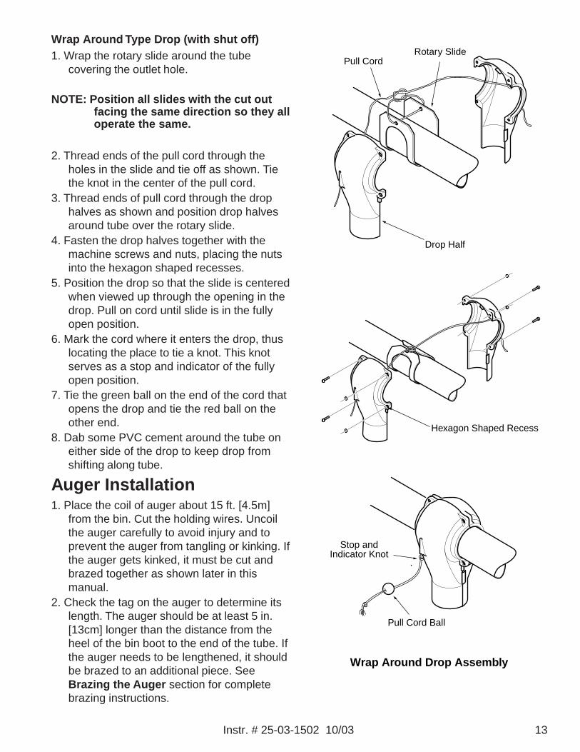
Wrap Around Type Drop (with shut off)1. Wrap the rotary slide around the tube
covering the outlet hole.
NOTE: Position all slides with the cut outfacing the same direction so they alloperate the same.
2. Thread ends of the pull cord through theholes in the slide and tie off as shown. Tiethe knot in the center of the pull cord.
3. Thread ends of pull cord through the drophalves as shown and position drop halvesaround tube over the rotary slide.
4. Fasten the drop halves together with themachine screws and nuts, placing the nutsinto the hexagon shaped recesses.
5. Position the drop so that the slide is centeredwhen viewed up through the opening in thedrop. Pull on cord until slide is in the fullyopen position.
6. Mark the cord where it enters the drop, thuslocating the place to tie a knot. This knotserves as a stop and indicator of the fullyopen position.
7. Tie the green ball on the end of the cord thatopens the drop and tie the red ball on theother end.
8. Dab some PVC cement around the tube oneither side of the drop to keep drop fromshifting along tube.
Auger Installation1. Place the coil of auger about 15 ft. [4.5m]
from the bin. Cut the holding wires. Uncoilthe auger carefully to avoid injury and toprevent the auger from tangling or kinking. Ifthe auger gets kinked, it must be cut andbrazed together as shown later in thismanual.
2. Check the tag on the auger to determine itslength. The auger should be at least 5 in.[13cm] longer than the distance from theheel of the bin boot to the end of the tube. Ifthe auger needs to be lengthened, it shouldbe brazed to an additional piece. SeeBrazing the Auger section for completebrazing instructions.
Wrap Around Drop Assembly
Pull Cord
Drop Half
Rotary Slide
Hexagon Shaped Recess
Stop and Indicator Knot
Pull Cord Ball
14 Instr. # 25-03-1502 10/03
IMPORTANT: Keep all brazed joints towardsthe bin end of the system wheneverpossible.
3. Push one end of the auger into the tubethrough the back end of the unloader valve.Continue to push auger into tube all the wayto power unit.
4. Rotate the power unit shaft to thread theauger into the locking clamp. It may benecessary to cut or file the end of the augerfirst so that it will fit into the clamp.
NOTE: With some models, it may benecessary to disconnect the switchhousing from the power unit toattach the auger.
5. When the auger is snugly fitted to the clamp,tighten the screw. Secure the tube to thepower unit with the clamp provided.
6. From unloader end, pull slack out of augerthen release. Cut auger flush with the endof the unloader.
7. Loosen set screw on clamp pin and installunloader arbor into auger until it touchesbearing thrust washer. Tighten clamp pinset screw. Insert the arbor into the back ofthe unloader and clamp.
CAUTION: Never get your fingers tangled inthe auger when it can move in thetube.
IMPORTANT: Do NOT stretch auger. Wearprotective gloves while pullingauger.
IMPORTANT: Check the inside of the binboot and unloader to be sure notools, parts or debris are in theboot.
8. Run the unit in 10 second bursts a few times.If the unit runs freely, tighten the motormount bolts and run the system about 10minutes without feed. This will de-burr thesystem and equalize the auger tension.
9. With the system shut off, fill the bulk bin.10. Run the Flex-vey Fill System.11. Check the feed drop(s) and switches to
make sure the system is functioningproperly.
12. After the slide is opened all the way, andthe feed is all the way to the far end of theauger and the system shuts off, close thefeed slide.
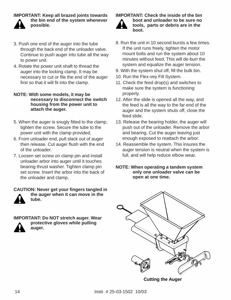
13. Release the bearing holder, the auger willpush out of the unloader. Remove the arborand bearing. Cut the auger leaving justenough exposed to reattach the arbor.
14. Reassemble the system. This insures theauger tension is neutral when the system isfull, and will help reduce elbow wear.
NOTE: When operating a tandem systemonly one unloader valve can beopen at one time.
Cutting the Auger

Instr. # 25-03-1502 10/03 15
Braze Joint
Brazing the AugerBig Dutchman auger is made of a specially
hardened steel that requires specificprocedures during the brazing process. Thefollowing instructions should be followedcarefully to assure a strong, smooth joint.
Equipment needed for brazing:• Welding Torch• Bronze Brazing Rod with Flux• 2 ft. [.6m] length of Angle Iron• 2 Locking Pliers• Approx. 1 qt. [1liter] of near boiling water
1. File the rough ends of the auger smooth.Clean oily coating from last full turn ofauger.
2. Align and clamp the two auger ends on alength of angle iron.
3. Butt the two ends of the auger approximatelyhalf a turn.DO NOT:• apply any pressure that couldcause misalignment• hook the auger ends inside eachother• butt more than 3/4 of a turn.
4. Use a brazing torch to uniformly heat the firsttwo full turns of auger, one turn in eachdirection from the joint.
5. Heat the brazing rod tip and dip it in the flux,while continuing to heat the auger to nearlywhite hot. Apply brazing rod. The near whiteheat stage should allow the brazing materialto flow into the joint. It will appear to bedrawn into the joint.
NOTE: Do NOT add unnecessary amountsof rod. Excessive material on theauger will interfere with the flow offeed.
6. When brazing is completed, reheat the area(two turns of the auger) uniformly to cherryred. Quench with near boiling water.
7. To complete the job, the brazed area must betempered. Uniformly reheat the two-turnarea for a short time (to a straw color). Thiswill draw the steel from a very hardcondition to a desirable spring temper.
CAUTION: Do NOT heat auger to red hotduring this tempering process. Toomuch heat at this point will softenthe steel. If the auger is overheatedduring this process, repeat thetempering process.
8. After the joint has cooled, file off any burrs orexcessively high spots.
IMPORTANT: Keep all brazed joints towardsthe bin end of the system wheneverpossible.
Braze Joint
YES NO

Big Dutchman, Inc. Limited Warranty1. Big Dutchman warrants to the original purchaser that as to any product of its manufacture proving to be defective in
material or workmanship under normal and intended use and service within one year from date of purchase thereof BigDutchman will, at its option, (a) repair or replace such product free of charge, or (b) in lieu of repair or replacement, refundto the original purchaser the original purchase price less the reasonable value of the product’s use to the originalpurchaser.
2. Any component parts that are not manufactured by Big Dutchman, such as electrical motors and controls, are excludedfrom this warranty, although such parts may be covered by separate warranties of the respective manufacturers. Copies ofthose other warranties, if any, may be obtained through Big Dutchman.
3. This warranty does not apply if all components of a system are not supplied by Big Dutchman, or if the product is notpurchased from and installed by an authorized Big Dutchman distributor or company warehouse, or installed and operatedin accordance with Big Dutchman specifications and instructions.
4. This warranty does not cover malfunctions or failures resulting from misuse, abuse, negligence, alterations, unauthorizedor improper repairs, accident, damage while in transit, or lack of authorized or proper maintenance or installation. Inaddition, this warranty does not cover normal wear and tear or any problem with a product not caused by a defect in BigDutchman materials or workmanship.
5. The obligations of Big Dutchman under this warranty do not include shipping charges, labor (whether for dismantling,installing, replacing or repairing), travel and subsistence allowance.
6. This warranty applies only to systems for the care of poultry and livestock. It does not apply to industrial or commercialinstallation. In addition, with respect to Big Dutchman’s breeder nest system, Big Dutchman makes no warranty orguarantee that individual birds or any given population of birds will utilize the nests.
7. Warranty claims must be made in writing to Big Dutchman within 20 days of discovery and In accordance with BigDutchman’s published return-goods procedures, a copy of which may be obtained from Big Dutchman. For this warrantyto apply, the product must be returned to a facility specified by Big Dutchman, freight prepaid and insured with proof oforiginal purchase and date.
8. The acceptance by Big Dutchman of any product for repair, replacement or refund will not be deemed an admission byBig Dutchman that the product is defective or in violation of any warranty. Products that are replaced or for which a refundis issued become the property of Big Dutchman.
9. The rights and obligations of the purchaser under this warranty may neither be assigned nor delegated without the priorwritten permission of an authorized officer of Big Dutchman.
10. This warranty contains the entire warranty agreement between Big Dutchman and the purchaser, and the terms andconditions of this warranty supersede any and all other understandings, representations or proposals between BigDutchman and the purchaser with respect to the matters covered by this warranty. This warranty shall not be modified byany custom or practice of the trade or of the parties, nor by any instances of Big Dutchman’s waiver of or failure toenforce any of the provisions of this warranty.
11. This warranty may be modified or amended only in writing signed by both the purchaser and an authorized officer of BigDutchman, and no other agent, employee, salesman, representative, dealer or distributor is authorized to make or to bindBig Dutchman to any representation, affirmation or warranty concerning the products in any manner whatsoever.
12. If Big Dutchman fails to fulfill its obligations in this warranty, or if Big Dutchman is determined to be liable to the purchaseror any other person for any reason related to any product covered by this warranty or the sale of that product, themaximum amount of damages, whether arising out of tort, contract, negligence or otherwise, recoverable from BigDutchman by the purchaser shall be limited to the purchase price of the product with respect to which Big Dutchman’sobligations or liability arises, less the reasonable value of the product’s use to the purchaser.
13. THE OBLIGATIONS AND LIABILITIES OF BIG DUTCHMAN AND THE RIGHTS AND REMEDIES OF THE PURCHASERUNDER THIS WARRANTY ARE EXCLUSIVE AND IN LIEU OF ALL OTHER WARRANTIES, GUARANTEES,OBLIGATIONS, LIABILITIES, RIGHTS AND REMEDIES, EXPRESSED OR IMPLIED, ARISING BY LAW OROTHERWISE, INCLUDING BUT NOT LIMITED TO THE IMPLIED WARRANTY OF MERCHANTABILITY, THE IMPLIEDWARRANTY OF FITNESS FOR A PARTICULAR PURPOSE, AND ANY IMPLIED OR EXPRESSED WARRANTYARISING FROM THE COURSE OF PERFORMANCE, COURSE OF DEALING OR USAGE OR TRADE. BIGDUTCHMAN SHALL HAVE NO OBLIGATION OR LIABILITY, WHETHER UNDER THIS WARRANTY OR OTHERWISE,FOR INCIDENTAL, CONSEQUENTIAL OR SPECIAL DAMAGES, LOST PROFITS, REVENUE OR OTHER INCOME,LOSS OF USE, DAMAGES FOR INJURY TO PERSONS OR PROPERTY, OR ANY OTHER DAMAGES.
14. Some states do not allow limitations on how long an implied warranty lasts or the exclusion or limitation of incidental orconsequential damages, so the above limitations and exclusions may not apply to each purchaser. This warranty gives thepurchaser specific legal rights, and the purchaser may have other rights that vary from state to state.
GermanyP.O. Box 11 63 • D-49360 Vechta • Germanytel +49 (0) 44 47 801 0 • fax +49 (0) 44 47 801 237www.bigdutchman.com • [email protected]. 25 Jalan Pemberita (U1/49), Temasya Industrial Park40150 Shah Alam • Selangor Darul Ehsan • Malaysiatel +603 5569 2320 • fax +603 5569 [email protected]
USAP.O. Box 1017 • Holland, MI 49422-1017 • USAtel +1 616 392 5981 • fax +1 616 392 6188www.bigdutchman.com • [email protected] Postal 84 Rua Victorio Milani, 125 Caxias do Sul, RS 95095-107 Brasiltel +55 (0) 54 226 2200 • fax +55 (0) 54 226 1424www.bigdutchman.com.br [email protected]
•
•
•