flex series universal controller
TRANSCRIPT

CONNECT SYSTEMS INCORPORATED 1802 Eastman Ave., Suite 116
Ventura, Ca. 93003
Phone (805) 642-7184 Fax (805) 642-7271
FLEX SERIES UNIVERSAL CONTROLLER
Hardware Reference Manual
Made in U.S.A. Copyright 2003 By Connect Systems Inc.
Connect Systems Inc. – Hardware Reference Manual Page 1

CONNECT SYSTEMS INCORPORATED 1802 Eastman Ave., Suite 116
Ventura, Ca. 93003
Phone (805) 642-7184 Fax (805) 642-7271
FLEX SERIES UNIVERSAL CONTROLLER
Hardware Reference Manual
VERSION 1.00 Made in U.S.A. Copyright 2003 By Connect Systems Inc.
Connect Systems Inc. – Hardware Reference Manual Page 2

TABLE OF CONTENTS
TEN POSITION SCREW TYPE OF TERMINAL BLOCK 4 FRONT PANEL DB9 CONNECTOR (FEMALE) 6 BACK PANEL DB9 CONNECTOR (MALE) 6 BACK PANEL PROGRAMMING JACK 7 BACK PANEL TELEPHONE JACK 7 ADJUSTMENTS 8 JUMPER STRAP OPTIONS 10 GENERAL CIRCUIT DESCRIPTION 12 REVISION HISTORY 15 PARTS LIST 16 SCHEMATICS 23
Connect Systems Inc. – Hardware Reference Manual Page 3

TEN POSITION SCREW TYPE OF TERMINAL BLOCK RX AUDIO For the products detecting CTCSS, DCS, or LTR, or
products that use the internal squelch, the RX AUDIO must be connected to the discriminator of the radio. For all other products the RX AUDIO can be connected to the discriminator, high side of the volume control, or the speaker.
TX AUDIO For products that generate CTCSS, DCS, or LTR, the TX
AUDIO must be connected directly to the modulator of the transmitter. For LTR and DCS, the modulator must be true FM. For CTCSS the modulator can be phase modulated or FM modulated. For all other applications, connections to the high side of the microphone is acceptable.
It should be noted that in most communication controllers there is a separate line for voice audio and a separate line for the CTCSS, DCS, or LTR signals. This is because to combine the two the controller has to have a limiter on the voice line to prevent over modulation and other undesirable side effects. The Flex Series Controllers has a built in limiter thereby not requiring separate lines.
PTT The PTT normally hooks to the PTT of the transmitter. If
you are using a Hand Held with the PTT sharing a common connection with the transmit audio, then attach a resistor with a value between 2.4K and 4.7K from the PTT to the TX Audio and attach the TX audio line to the center conductor of the microphone cable. In most product that use the PTT, the AUX relay can also be used as a PTT connection. This has the advantage of allowing positive keying or other situations where the normal open collector PTT does not work.
COS Connect to a point that has a good voltage swing when
the squelch is opened/closed. The best point to connect is to the collector of the transistor that controls the busy light (if the receiver has one). Otherwise you may connect to the squelch control voltage. The minimum voltage for the COS is about 0 volts and the Maximum voltage is the supply voltage.
Some radios have that point coming out the back of the
radio. It sometimes goes under the name of squelch detect, sq det, or COR. In some case a pull up or pull down resistor is necessary.
The polarity and other parameters associated with the COS is contained within the programming parameters
Connect Systems Inc. – Hardware Reference Manual Page 4

described later. It should be noted that in most cases, the COS can be replaced with the internal squelch.
SENSE This point is used as an auxiliary input for specialized
purposes in certain products. As an example, this input may be used to detect the presence of a CTCSS/DCS signal in an LTR system. The minimum voltage for the sense input is about 0 volts and the Maximum voltage is the supply voltage.
The polarity and other parameters associated with the
SENSE is contained within the programming parameters if used.
AUX RELAY These two points connects to the center contact and
normally open contact of the relay. The use if any depends upon the product.
+12 VDC Connect to a source of 12 volts to 15 volts DC. The Flex
Series Controllers are reverse polarity protected, so a polarity mistake will not damage the product. Connect the return lead to ground.
GND The two grounds in the system are internally connected
to each other.
Connect Systems Inc. – Hardware Reference Manual Page 5

FRONT PANEL DB9 CONNECTOR (Female) This connector is used for programming the system using a lap top computer or a desk top computer or as a serial output port for certain products such as the Communication decoder. Programming will be via a Microsoft windows based program that will be available at no charge sometime next year. Pin 1: -6 volts Pin 2: transmit (data from flex to P.C.) Pin 3: receive (data from P.C. to flex) Pin 4: not used Pin 5: ground Pin 6: -6 volts Pin 7: not used Pin 8: -6 volts Pin 9: not used
BACK PANEL DB9 CONNECTOR (Male) This connector is used for programming the system via an external odem. m Programming will be via a Microsoft windows based program that will be available at no charge sometime next year. Pin 1: not used Pin 2: receive (data from P.C. to flex) Pin 3: transmit (data from flex to P.C.) Pin 4: -6 volts Pin 5: ground Pin 6: not used Pin 7: not used Pin 8: not used Pin 9: not used
Connect Systems Inc. – Hardware Reference Manual Page 6

BACK PANEL PROGRAMMING JACK This jack serves three purposes:
1. By plugging a telephone in the back, the user can program the various parameters as allowed by the system by means of the 12 position keypad on the telephone.
2. The mouth piece of the telephone can be used for storing voice prompts in the system.
3. Can be used for communications with other Flex Series Controllers via a RS485 Interface.
Pin 1: not used Pin 2: RS485 Connection Pin 3: Tip for telephone Pin 4: Ring for telephone Pin 5: RS485 Connection P in 6: not used
BACK PANEL TELEPHONE JACK This jack connect to the telephone line and is used for the following purposes:
1. Remote programming via a telephone 2. Telephone to radio and radio to telephone connection as in
a phone patch 3. Input device for a paging terminal to allow the remote
telephone to initiate a page.
Pin 1: not used Pin 2: not used Pin 3: Tip for telephone Pin 4: Ring for telephone Pin 5: not used Pin 6: not used
Connect Systems Inc. – Hardware Reference Manual Page 7

ADJUSTMENTS P1 HYB BAL The Hybrid Balance control is used to null out the
mobile return audio in full duplex mode. The alignment must take place on one of the phone lines the Flex Series controller will be serving. (This alignment can not be done at the shop prior to delivery to the site.)
Have a mobile place a call through the Flex Series Controller. The party answering the called phone should leave the phone off hook during the alignment procedure.
Monitor the transmitter output with a service
monitor or connect an oscilloscope to the "TX OUTPUT" terminal on the rear of the Flex Series Controller. Place all four Dip switches in the off position.
Have the mobile simultaneously press digits 3 and 6 on his touch tone keypad. This will result in the transmission of a single 1477 Hz tone.
Adjust the "HYB BAL" Potentiometer to produce the least audio output. Try all possible dip position combinations and null each time. The combination which gives the minimum output is the correct position to use.
Changes made within the telephone company or rerouting of telephone lines could occasionally require re-adjustment of the hybrid.
P3 TEL VOX Used for detection of call progress tones and
sensitivity to voice in Vox operated applications. Turning the pot clockwise increases its sensitivity.
P4 PREAMP The preamp control is used to match the audio level
from your receiver to the Flex Series controller. To adjust, a signal containing 100 Hz CTCSS with about 600 Hz deviation should be applied to the receiver. Adjust the preamp control until a level of 3 volts peak to peak is observed at test point 6. If an oscilloscope is not available, read 1 volt RMS using a VOM.
P5 RX VOX Used in VOX mode only. Sets RX audio triggering
sensitivity. Should be fully clockwise in VOX simplex applications. Reduce setting when used through repeaters if land line cannot respond to
Connect Systems Inc. – Hardware Reference Manual Page 8

mobile during hang time due to noise or tone on the repeater carrier.
P6 AUDIO OUT Adjust the maximum level going to the transmitter.
When turned fully clockwise, an output voltage of about five volts peak to peak is obtained. In most case the output level can also be set in the programming mode.
P7 CONTRAST Sets the contrast of the LCD. Adjust to what is
most pleasing to the individual. P8 SQUELCH Advance clockwise to a point just beyond where the
front panel display "Rx" message disappears. Not all products will display the Rx message.
Connect Systems Inc. – Hardware Reference Manual Page 9

JUMPER STRAP OPTIONS JP1 Line In Use Detector. When inserted, enables line
in use detection. That allows the system to detect if another phone in parallel with the controller is off hook. Will only work with a phone system where the nominal on hook voltage is about 48 volts.
JP2,JP18 Preamp Gain. With jumper 18 not installed and
Jumper 2 not installed, gain is 100 with flat audio.
With jumper 18 not installed and Jumper 2 in “A” position, gain is 10 with flat audio. With Jumper 18 not installed and Jumper 2 in “B” position, gain is 10 with a 3 db roll off starting at 300 Hz. With jumper 18 installed and Jumper 2 not installed, gain is 100 with 3 db roll off starting at 300 Hz. With jumper 18 installed and jumper 2 in “A” position, has a gain of 10 with 3 db roll off starting at 3 KHz. With jumper 18 installed and jumper 2 in “B” position, has a gain of 10 with a 3 db roll off starting at 300 Hz.
JP3 Product Specific. See product manual JP4 Product Specific. See product manual JP5 Product Specific. See product manual JP6 Product Specific. See product manual JP7 Product Specific. See product manual JP8 Product Specific. See product manual JP9 Product Specific. See product manual JP10 Product Specific. See product manual JP11 Selects the radio audio source to be either pre-
emphasized or flat JP12,JP13 RS232 Source. Determines if the source of the RS232
port is from the internal UART of the microprocessor or from two general I/O pins. Used for future products.
JP14 When connected, this allows a secondary D/A
converter to be connected to pin 9 of the 10 position screw type of terminal block. When used in this mode, the aux relay cannot be used.
Connect Systems Inc. – Hardware Reference Manual Page 10
JP15 The terminating resistor when used for RS485
communication. Only use one per system. JP16 When inserted, allows the TX Audio output to be DC
coupled. JP17 Connects pin 6 of 10 position screw type of
terminal block to the internal circuitry of the system. Should normally be connected. Only used for testing purposes.
JP18 See JP2 JP19 Selects the audio source for the voice recorder to
be either from the telephone/programming jack or the radio
JP20 Selects the telephone audio source to be either
pre-emphasized or flat
Connect Systems Inc. – Hardware Reference Manual Page 11

GENERAL CIRCUIT DESCRIPTION
Telephone Interface Telephone call comes in Telco Jack J1. If the voltage exceeds about 250 volts, the two varistors, V1 and V2 will conduct and blow the two fuses F1 and F2. This protects against lightning and other high voltage transients on the telephone line. If the systems gets a ringing voltage, the optoisolator Q1 will conduct and the output RD1 will present a square wave at the microprocessor whose frequency is the same as the incoming ringing frequency. The microprocessor will determine if it’s a valid ringing signal. The optoisolator Q2 determines if the voltage on the telephone is about 48 volts. If it is the signal LB1 will be grounded. If the voltage goes below about 48 volts that point will be high. When the telephone line is connected and the line relay is pulled in, then the two optoisolaters Q3 and Q4 will indicate the presence of loop current and the direction of the current. This circuit allows the system to determine if the phone line has been hung up by a momentary loss of loop current of a reversal of the loop current. The hybrid transformers T1 and T2 along with the balancing network allows the system to separate the receive and transmit audio. This is only necessary in a full duplex phone patch. Receive Telephone Audio The output of T1 is presented to U1D where the Op-Amp provides an anti-aliasing filter to the Voice storage chip U17 and the DTMF decoder U3. The receive telephone audio passes to the Analog to Digital Converter on the microprocessor as the signal AD_TELCO and to the circuitry surrounding U1A where the function of Telephone Vox is implemented. U18-C will pre-emphasize the telephone audio if the audio out is going to directly feed the modulator of the transmitter. Transmit Telephone Audio The output of the Digital to Analog Converter from the microprocessor (DA_TELCO) is passed to U19 which forms a five pole low pass filter. This circuitry is needed properly reconstruct the data coming from the microprocessor. U1B provides gain before being outputted to the telephone line. Voice Storage Chip
Connect Systems Inc. – Hardware Reference Manual Page 12

The voice storage chip is used to store up to two minutes of voice from either the telephone, programming port, or the radio. The connection from the radio to the voice storage chip is not always direct (dependent on Jumper 19). To accomplish this task, the unit digitizes the voice from the radio and then outputs it to the telephone. If the telephone line relay is not pulled in or the system is not connected to the telephone line, then the hybrid is not balanced and the audio to the telephone output will be reflected back to the telephone audio input where it then has a clear path to the voice storage chip. Telephone DTMF Decoder The audio from the telephone is decoded by the DTMF decoder U3. When pin 15 on the DTMF decoder chip is high, it signals to the microprocessor pin that data is waiting where it is then read. Radio Receive Audio U5A provides a low pass filter used to get rid of high frequency garbage from the radio. U5B provides the de-emphasis network. The audio from U5B goes to the RX-VOX, DTMF decoder, zero crossing detector, and the 6 pole high pass filter consisting of U10A, U10B, and U10D. The output of the filter is used to remove sub audible CTCSS,DCS, or LTR tones from the radio before being presented to the microprocessors A/D converter. U5-D will pre-emphasize the radio audio if the receive out is going to directly feed the modulator of the transmitter. The receive audio also goes to U13A-U13D, U18A and U18B which is a squelch detector. The squelch detector is used to determine the presence of squelch noise from the radio receiver. Radio Transmit Audio The output of the microprocessors D/A converter is reconstructed by U20, a five pole low pass filter. U4C is used to get rid of any high frequency clock noise from the audio and U4D is used to amplify the results before being presented as transmit audio. Squelch Detector U13A and U13B act as a four pole high pass filter to remove any low frequency signals below about 11KHz. U13 act as a gain stage where it is then detected by U13D. R110 and C92 act as a smoothing filter where it is then presented to the microprocessor via U18B Zero Crossing Detector U6D and U6C act as a four pole low pass filter designed to pass only the CTCSS, DCS or LTR subaudible signals. U6A and U6B along
Connect Systems Inc. – Hardware Reference Manual Page 13

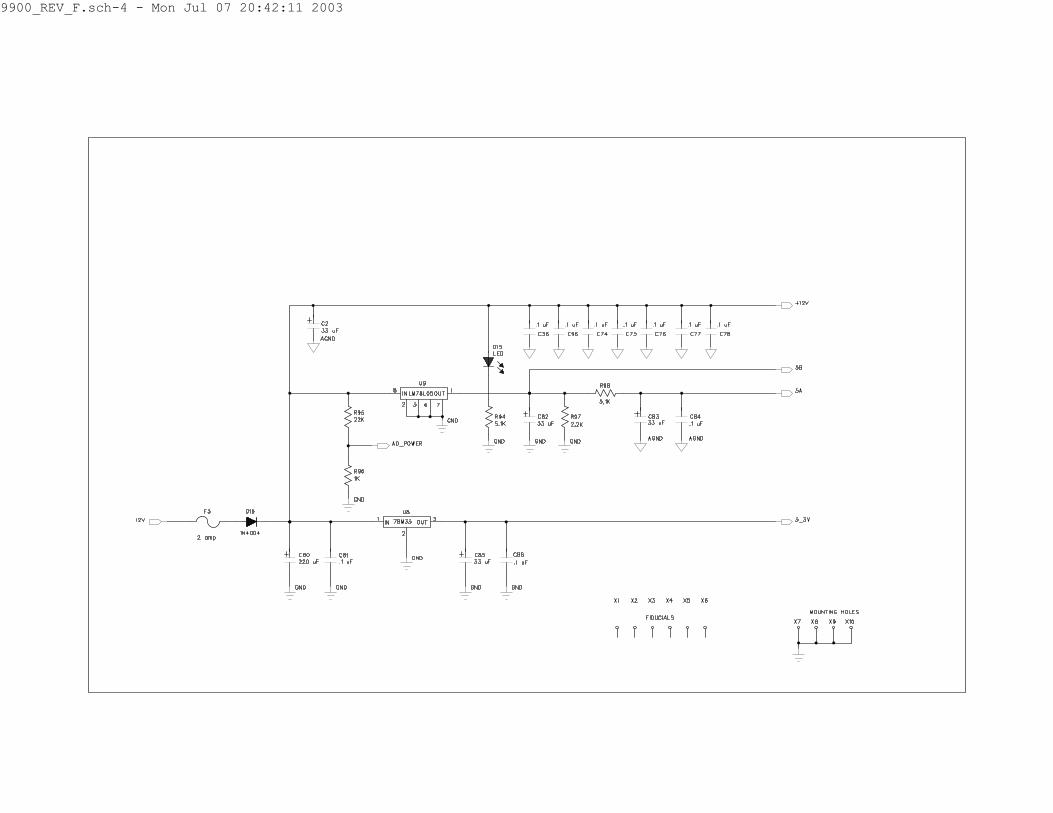
with the transistors act as a zero crossing detector where it is then presented as a digital signal to the microprocessor. COS Detector U4B acts as a buffer between the outside world and the A/D converter on the microprocessor. The logic within the microprocessor determines if the COS should be derived from the COS detector or the Squelch detector. Push To Talk Transistor Q9 acts as a buffer between the microprocessor and the outside world. D14 is used to protect the circuit against any transients. Sense Detector U4A acts as a buffer between the outside world and the A/D converter on the microprocessor. The logic within the microprocessor determines the function of that signal. EEPROM The EEPROM is used for parameter storage and occasionally certain real time data. The part is read and written to by the IIC port on the microprocessor. Computer Interface U12 converts the RS232 levels to levels compatible with the UART internal to the microprocessor or the port pins, dependent on how JP12 and JP13 are jumpered. External Network U16 converts the levels from the second UART built into the microprocessor to the appropriate levels compatible with RS485 communications. This can be used to tie multiple flex series controller together. LCD Interface The microprocessor talks to the LCD controller via a four bit interface. Aux Relay The microprocessor can turn on and off the auxiliary relay by means of a control pin attached to R93. JTAG Interface The microprocessor can be reprogrammed via a JTAG interface. This allows the user to change the characteristic of the controller by means of software available on our web site. Power Supply The power supply generates 5 volts, and 3.3 volts from a 12 volt or greater power source.
Connect Systems Inc. – Hardware Reference Manual Page 14

Connect Systems Inc. – Hardware Reference Manual Page 15

REVISION HISTORY
July 6, 2003 First Release
Connect Systems Inc. – Hardware Reference Manual Page 16

-------------------------------------------------------------------------------- CONNECT SYSTEMS INC. | PARTS LIST | REV F | 1802 EASTMAN AVE #116 | PCBA, MODEL 9900 | | VENTURA, CA. 93003 | | | | SHEET 1 OF 7 | | -------------------------------------------------------------------------------- DRAWN BY J. WANGER |APPROVED |DATE APPROVED | -------------------------------------------------------------------------------- | QTY | | | ITEM | UNIT | ISSUED |DESCRIPTION |REF DESIGNATION | =====|======|=========|=======================================|================| 1 | 1 | |P.C.B., MODEL 9900 |MODEL 9900 | -----|------|---------|---------------------------------------|----------------| 3 | 4 | |CAP, SMD 0805, 33 pF 08055A330JAT2A |C43,C50,C60,C61 | -----|------|---------|---------------------------------------|----------------| 2 | 1 | |CAP, SMD 0805, 82 pF 08055A820JAT2A |C102 | -----|------|---------|---------------------------------------|----------------| 4 | 5 | |CAP, SMD 0805, 120 pF 08055A121JAT2A |C9,C25,C30,C99, | -----|------|---------|---------------------------------------|----------------| 5 | | | |C104 | -----|------|---------|---------------------------------------|----------------| 6 | 1 | |CAP, SMD 0805, 270 pF 08055A271JAT2A |C13 | -----|------|---------|---------------------------------------|----------------| 7 | | | | | -----|------|---------|---------------------------------------|----------------| 8 | 5 | |CAP, SMD 0805, .001 uF 008055C102JAT2A |C54,C70,C71,C72,| -----|------|---------|---------------------------------------|----------------| 9 | | | |C73 | -----|------|---------|---------------------------------------|----------------| 10 | 5 | |CAP, SMD 0805, .0022 uF 08055C222JAT2A |C10,C87,C88,C89,| -----|------|---------|---------------------------------------|----------------| 11 | | | |C90 | -----|------|---------|---------------------------------------|----------------| 12 | 2 | |CAP, SMD 0805, .0047 uF 08055C472JAT2A |C28,C38 | -----|------|---------|---------------------------------------|----------------| 13 | 10 | |CAP, SMD 0805, .01 uF 08055C103JAT2A |C6,C24,C40,C44, | -----|------|---------|---------------------------------------|----------------| 14 | | | |C45,C46,C47,C48,| -----|------|---------|---------------------------------------|----------------| 15 | | | |C49,C91 | -----|------|---------|---------------------------------------|----------------| 16 | | | | | -----|------|---------|---------------------------------------|----------------| 17 | 1 | |CAP, SMD 0805, .015 uF 08055C153JAT2A |C39 | -----|------|---------|---------------------------------------|----------------| 18 | 1 | |CAP, SMD 0805, .022 uF 08055C223JAT2A |C7 | -----|------|---------|---------------------------------------|----------------| 19 | 3 | |CAP, SMD 0805, .047 uF 08055C473JAT2A |C11,C27,C37 | -----|------|---------|---------------------------------------|----------------| 20 | | | | | -----|------|---------|---------------------------------------|----------------| 21 | | | | | -----|------|---------|---------------------------------------|----------------| 22 | | | | | -----|------|---------|---------------------------------------|----------------| 23 | | | | | -----|------|---------|---------------------------------------|----------------| 24 | | | | | -----|------|---------|---------------------------------------|----------------|
Connect Systems Inc. – Hardware Reference Manual Page 17

-------------------------------------------------------------------------------- CONNECT SYSTEMS INC. | PARTS LIST | REV F | 1802 EASTMAN AVE #116 | PCBA, MODEL 9900 | | VENTURA, CA. 93003 | | | | SHEET 2 OF 7 | | -------------------------------------------------------------------------------- DRAWN BY J. WANGER |APPROVED |DATE APPROVED | -------------------------------------------------------------------------------- | QTY | | | ITEM | UNIT | ISSUED |DESCRIPTION |REF DESIGNATION | =====|======|=========|=======================================|================| 25 | 45 | |CAP, SMD 0805, .1 uF 08055C104KAT2A |C1,C4,C12,C16, | -----|------|---------|---------------------------------------|----------------| 26 | | | |C17,C19,C20,C21,| -----|------|---------|---------------------------------------|----------------| 27 | | | |C22,C23,C32,C33,| -----|------|---------|---------------------------------------|----------------| 28 | | | |C34,C36,C41,C42,| -----|------|---------|---------------------------------------|----------------| 29 | | | |C55,C56,C57,C59,| -----|------|---------|---------------------------------------|----------------| 30 | | | |C62,C63,C64,C65,| -----|------|---------|---------------------------------------|----------------| 31 | | | |C66,C67,C68,C74,| -----|------|---------|---------------------------------------|----------------| 32 | | | |C75,C76,C77,C78,| -----|------|---------|---------------------------------------|----------------| 33 | | | |C79,C81,C84,C86,| -----|------|---------|---------------------------------------|----------------| 34 | | | |C93,C96,C97,C98,| -----|------|---------|---------------------------------------|----------------| 35 | | | |C100,C101,C107, | -----|------|---------|---------------------------------------|----------------| 36 | | | |C115,C116 | -----|------|---------|---------------------------------------|----------------| 37 | 1 | |CAP, SMD 0805, .22 uF 08053C224KAT2A |C29 | -----|------|---------|---------------------------------------|----------------| 38 | 1 | |CAP, .47 uF, 250V, EF2474-NO |C3 | -----|------|---------|---------------------------------------|----------------| 39 | 6 | |CAP, 1 uF, 50V, ELECT, 50TWSS1 |C5,C14,C15,C18, | -----|------|---------|---------------------------------------|----------------| 40 | | | |C31,C92 | -----|------|---------|---------------------------------------|----------------| 41 | | | | | -----|------|---------|---------------------------------------|----------------| 42 | 2 | |CAP, 2.2 uF, 50V, ELECT, 50TWSS2R2 |C94,C95 | -----|------|---------|---------------------------------------|----------------| 43 | 3 | |CAP, 4.7 uF, 50V, ELECT, 50TWSS4R7 |C26,C51,C58 | -----|------|---------|---------------------------------------|----------------| 44 | 1 | |CAP, 10 uF, 50V, ELECT, 50TWSS10 |C8 | -----|------|---------|---------------------------------------|----------------| 45 | 4 | |CAP, 33 uF, 25V, ELECT, 25TWSS33 |C2,C82,C83,C85 | -----|------|---------|---------------------------------------|----------------| 46 | | | | | -----|------|---------|---------------------------------------|----------------| 47 | | | | | -----|------|---------|---------------------------------------|----------------| 48 | 2 | |CAP, 47 uF, 35V, ELECT, 35TWSS47 |C35,C103 | -----|------|---------|---------------------------------------|----------------|
Connect Systems Inc. – Hardware Reference Manual Page 18

-------------------------------------------------------------------------------- CONNECT SYSTEMS INC. | PARTS LIST | REV F | 1802 EASTMAN AVE #116 | PCBA, MODEL 9900 | | VENTURA, CA. 93003 | | | | SHEET 3 OF 7 | | -------------------------------------------------------------------------------- DRAWN BY J. WANGER |APPROVED |DATE APPROVED | -------------------------------------------------------------------------------- | QTY | | | ITEM | UNIT | ISSUED |DESCRIPTION |REF DESIGNATION | =====|======|=========|=======================================|================| 49 | 5 | |CAP, 220 uF, 35V, ELECT, 35TWSS220 |C52,C53,C80, | -----|------|---------|---------------------------------------|----------------| 50 | | | |C105,C106 | -----|------|---------|---------------------------------------|----------------| 51 | 2 | |CONNECTOR, RJ11, 6 POS, 66011-002 |J1-J2 | -----|------|---------|---------------------------------------|----------------| 52 | 1 | |CONNECTOR, 10 POS BARR BLK 70810C |J3 | -----|------|---------|---------------------------------------|----------------| 53 | 1 | |CONNECTOR, 8P HDR, LONG PIN, 22-03-2082|J4 | -----|------|---------|---------------------------------------|----------------| 54 | 1 | |CONNECTOR, DB9P, RT ANG, DE9P318,104942|J6 | -----|------|---------|---------------------------------------|----------------| 55 | 1 | |CONNECTOR, DP9S, RT ANG, DE9S318,104951|J5 | -----|------|---------|---------------------------------------|----------------| 56 | 1 | |CONNECTOR, 2 x 5,FAN-10SGS |J8 | -----|------|---------|---------------------------------------|----------------| 57 | 2 | |HEADER, 2 x 4 PIN TDB-08SGS |JP3-JP10 | -----|------|---------|---------------------------------------|----------------| 58 | 1 | |HEADER, 14 PIN, 2X7, 10-88-1141 |LCD | -----|------|---------|---------------------------------------|----------------| 59 | 6 | |CONNECTOR, 2 PIN HEADER, TD-2SG |JP1,JP14,JP15, | -----|------|---------|---------------------------------------|----------------| 60 | | | |JP16,JP17,JP18 | -----|------|---------|---------------------------------------|----------------| 61 | 6 | |CONNECTOR, 3 PIN HEADER, TD-3SG |JP2,JP11,JP12, | -----|------|---------|---------------------------------------|----------------| 62 | | | |JP13,JP19,JP20 | -----|------|---------|---------------------------------------|----------------| 63 | 20 | |CONNECTOR, SHORTING BLOCK, DM-2GM-0 |JP1-JP20 | -----|------|---------|---------------------------------------|----------------| 64 | 3 | |DIODE, 1N5245B,ZENER, 15V, CMBZ5245B |D1,D2,D14 | -----|------|---------|---------------------------------------|----------------| 65 | 3 | |DIODE, 1N4004 |D3,D16,D17 | -----|------|---------|---------------------------------------|----------------| 66 | 10 | |DIODE, 1N4148, MMBD4148 |D4,D5,D6,D7,D8, | -----|------|---------|---------------------------------------|----------------| 67 | | | |D9,D10,D11,D18, | -----|------|---------|---------------------------------------|----------------| 68 | | | |D19 | -----|------|---------|---------------------------------------|----------------| 69 | | | | | -----|------|---------|---------------------------------------|----------------| 70 | 1 | |LED ASSY, RED, LL64233R, LTL-523-11 |D15 | -----|------|---------|---------------------------------------|----------------| 71 | 1 | |LED, RED, SMALL, 35BL504 |D12 | -----|------|---------|---------------------------------------|----------------| 72 | | | | | -----|------|---------|---------------------------------------|----------------|
Connect Systems Inc. – Hardware Reference Manual Page 19

-------------------------------------------------------------------------------- CONNECT SYSTEMS INC. | PARTS LIST | REV F | 1802 EASTMAN AVE #116 | PCBA, MODEL 9900 | | VENTURA, CA. 93003 | | | | SHEET 4 OF 7 | | -------------------------------------------------------------------------------- DRAWN BY J. WANGER |APPROVED |DATE APPROVED | -------------------------------------------------------------------------------- | QTY | | | ITEM | UNIT | ISSUED |DESCRIPTION |REF DESIGNATION | =====|======|=========|=======================================|================| 73 | 2 | |FUSE, 255.250 |F1,F2 | -----|------|---------|---------------------------------------|----------------| 74 | 1 | |FUSE, 2 AMP, 473.002 |F3 | -----|------|---------|---------------------------------------|----------------| 75 | 2 | |I.C. H11AA4.S, OPTOISOLATOR |Q1,Q2 | -----|------|---------|---------------------------------------|----------------| 76 | 2 | |I.C. 4N25.S-M, OPTOISOLATOR |Q3,Q4 | -----|------|---------|---------------------------------------|----------------| 77 | 7 | |I.C. LF347M, QUAD OP AMP |U1,U4,U5,U6,U10,| -----|------|---------|---------------------------------------|----------------| 78 | | | |U13,U18 | -----|------|---------|---------------------------------------|----------------| 79 | 1 | |I.C. LM324M, QUAD OP AMP |U11 | -----|------|---------|---------------------------------------|----------------| 80 | 2 | |I.C. M-88L70-01S, DTMF DECODER |U3,U7 | -----|------|---------|---------------------------------------|----------------| 81 | 1 | |I.C. uA78M33CKC, 3.3 V REGULATOR |U8 | -----|------|---------|---------------------------------------|----------------| 82 | 1 | |I.C. LM78L05ACM, 5.0 V REGULATOR |U9 | -----|------|---------|---------------------------------------|----------------| 83 | 1 | |I.C. MAX5380LEUX, D/A CONVERTER |U2 | -----|------|---------|---------------------------------------|----------------| 84 | | | | | -----|------|---------|---------------------------------------|----------------| 85 | 1 | |I.C. MAX3221CAE, RS232 INTERFACE |U12 | -----|------|---------|---------------------------------------|----------------| 86 | 1 | |I.C. 24LC256I/SN, 256K IIC EEPROM |U14 | -----|------|---------|---------------------------------------|----------------| 87 | 1 | |I.C. C8051F124, MICROPROCESSOR |U15 | -----|------|---------|---------------------------------------|----------------| 88 | 1 | |I.C. SP3485CN, RS485 TRANCEIVER |U16 | -----|------|---------|---------------------------------------|----------------| 89 | | | | | -----|------|---------|---------------------------------------|----------------| 90 | 1 | |I.C. ISD4002-120S, VOICE RECORDER |U17 | -----|------|---------|---------------------------------------|----------------| 91 | 2 | |I.C. MAX7413CUA, 5th ORDER BESSEL FLTR |U19,U20 | -----|------|---------|---------------------------------------|----------------| 92 | | | | | -----|------|---------|---------------------------------------|----------------| 93 | 1 | |POT, 2K, 3386P-1-202 |P1 | -----|------|---------|---------------------------------------|----------------| 94 | 5 | |POT, 10K, 3386P-1-103 |P3,P4,P5,P6,P7 | -----|------|---------|---------------------------------------|----------------| 95 | 1 | |POT, 100K, 3386P-1-104 |P8 | -----|------|---------|---------------------------------------|----------------| 96 | | | | | -----|------|---------|---------------------------------------|----------------|
Connect Systems Inc. – Hardware Reference Manual Page 20

-------------------------------------------------------------------------------- CONNECT SYSTEMS INC. | PARTS LIST | REV F | 1802 EASTMAN AVE #116 | PCBA, MODEL 9900 | | VENTURA, CA. 93003 | | | | SHEET 5 OF 7 | | -------------------------------------------------------------------------------- DRAWN BY J. WANGER |APPROVED |DATE APPROVED | -------------------------------------------------------------------------------- | QTY | | | ITEM | UNIT | ISSUED |DESCRIPTION |REF DESIGNATION | =====|======|=========|=======================================|================| 97 | 2 | |RELAY, G5V-2-DC12 |RLY1,RLY2 | -----|------|---------|---------------------------------------|----------------| 98 | | | | | -----|------|---------|---------------------------------------|----------------| 99 | 1 | |RESISTOR, 1/2 W, 100, CARBON FILM |R13 | -----|------|---------|---------------------------------------|----------------| 100 | 3 | |RESISTOR, 1/2 W, 220, CARBON FILM |R9,R12,R14 | -----|------|---------|---------------------------------------|----------------| 101 | 1 | |RESISTOR, 1/2 W, 1K, CARBON FILM |R4 | -----|------|---------|---------------------------------------|----------------| 102 | 1 | |RESISTOR, 1/2 W, 22K, CARBON FILM |R3 | -----|------|---------|---------------------------------------|----------------| 103 | 1 | |RESISTOR, 1/2 W, 33K, CARBON FILM |R6 | -----|------|---------|---------------------------------------|----------------| 104 | 2 | |RESISTOR, 1/4 W, 620, CARBON FILM |R16,R20 | -----|------|---------|---------------------------------------|----------------| 105 | 1 | |RESISTOR, SMD 0805, 0 |R1 | -----|------|---------|---------------------------------------|----------------| 106 | 1 | |RESISTOR, SMD 0805, 100 |R21 | -----|------|---------|---------------------------------------|----------------| 107 | 1 | |RESISTOR, SMD 0805, 240 |R19 | -----|------|---------|---------------------------------------|----------------| 108 | 1 | |RESISTOR, SMD 0805, 470 |R52 | -----|------|---------|---------------------------------------|----------------| 109 | 1 | |RESISTOR, SMD 0805, 620 |R83 | -----|------|---------|---------------------------------------|----------------| 110 | 11 | |RESISTOR, SMD 0805, 1K |R26,R39,R59,R73,| -----|------|---------|---------------------------------------|----------------| 111 | | | |R78,R82,R84,R90,| -----|------|---------|---------------------------------------|----------------| 112 | | | |R96,R115,R136 | -----|------|---------|---------------------------------------|----------------| 113 | 2 | |RESISTOR, SMD 0805, 1.1K |R32,R64 | -----|------|---------|---------------------------------------|----------------| 114 | 1 | |RESISTOR, SMD 0805, 2K |R114 | -----|------|---------|---------------------------------------|----------------| 115 | 11 | |RESISTOR, SMD 0805, 2.2K |R17,R27,R44,R62 | -----|------|---------|---------------------------------------|----------------| 116 | | | |R85,R86,R87,R97,| -----|------|---------|---------------------------------------|----------------| 117 | | | |R107,R110,R127 | -----|------|---------|---------------------------------------|----------------| 118 | 1 | |RESISTOR, SMD 0805, 3.3K |R104 | -----|------|---------|---------------------------------------|----------------| 119 | 2 | |RESISTOR, SMD 0805, 4.7K |R43,R103 | -----|------|---------|---------------------------------------|----------------| 120 | | | | | -----|------|---------|---------------------------------------|----------------|
Connect Systems Inc. – Hardware Reference Manual Page 21

-------------------------------------------------------------------------------- CONNECT SYSTEMS INC. | PARTS LIST | REV F | 1802 EASTMAN AVE #116 | PCBA, MODEL 9900 | | VENTURA, CA. 93003 | | | | SHEET 6 OF 7 | | -------------------------------------------------------------------------------- DRAWN BY J. WANGER |APPROVED |DATE APPROVED | -------------------------------------------------------------------------------- | QTY | | | ITEM | UNIT | ISSUED |DESCRIPTION |REF DESIGNATION | =====|======|=========|=======================================|================| 121 | 15 | |RESISTOR, SMD 0805, 5.1K |R10,R25,R58,R72,| -----|------|---------|---------------------------------------|----------------| 122 | | | |R81,R91,R94,R98,| -----|------|---------|---------------------------------------|----------------| 123 | | | |R108,R109,R113, | -----|------|---------|---------------------------------------|----------------| 124 | | | |R119,R133,R134, | -----|------|---------|---------------------------------------|----------------| 125 | | | |R135 | -----|------|---------|---------------------------------------|----------------| 126 | 2 | |RESISTOR, SMD 0805, 8.2K |R63,R106 | -----|------|---------|---------------------------------------|----------------| 127 | 2 | |RESISTOR, SMD 0805, 10K |R38,R41 | -----|------|---------|---------------------------------------|----------------| 128 | 1 | |RESISTOR, SMD 0805, 12K |R70 | -----|------|---------|---------------------------------------|----------------| 129 | 1 | |RESISTOR, SMD 0805, 13K |R105 | -----|------|---------|---------------------------------------|----------------| 130 | 2 | |RESISTOR, SMD 0805, 15K |R30,R47 | -----|------|---------|---------------------------------------|----------------| 131 | 2 | |RESISTOR, SMD 0805, 18K |R29,R46 | -----|------|---------|---------------------------------------|----------------| 132 | 3 | |RESISTOR, SMD 0805, 22K |R22,R31,R95 | -----|------|---------|---------------------------------------|----------------| 133 | 2 | |RESISTOR, SMD 0805, 27K |R18,R116 | -----|------|---------|---------------------------------------|----------------| 134 | 16 | |RESISTOR, SMD 0805, 33K |R2,R8,R65,R68, | -----|------|---------|---------------------------------------|----------------| 135 | | | |R79,R80,R88,R89,| -----|------|---------|---------------------------------------|----------------| 136 | | | |R92,R93,R99, | -----|------|---------|---------------------------------------|----------------| 137 | | | |R100,R101,R102, | -----|------|---------|---------------------------------------|----------------| 138 | | | |R112,R126 | -----|------|---------|---------------------------------------|----------------| 139 | 3 | |RESISTOR, SMD 0805, 47K |R66,R67,R76 | -----|------|---------|---------------------------------------|----------------| 140 | 2 | |RESISTOR, SMD 0805, 51K |R53,R54 | -----|------|---------|---------------------------------------|----------------| 141 | 3 | |RESISTOR, SMD 0805, 62K |R55,R56,R69 | -----|------|---------|---------------------------------------|----------------| 142 | 1 | |RESISTOR, SMD 0805, 75K |R51 | -----|------|---------|---------------------------------------|----------------| 143 | | | | | -----|------|---------|---------------------------------------|----------------| 144 | | | | | -----|------|---------|---------------------------------------|----------------|
Connect Systems Inc. – Hardware Reference Manual Page 22

-------------------------------------------------------------------------------- CONNECT SYSTEMS INC. | PARTS LIST | REV F | 1802 EASTMAN AVE #116 | PCBA, MODEL 9900 | | VENTURA, CA. 93003 | | | | SHEET 7 OF 7 | | -------------------------------------------------------------------------------- DRAWN BY J. WANGER |APPROVED |DATE APPROVED | -------------------------------------------------------------------------------- | QTY | | | ITEM | UNIT | ISSUED |DESCRIPTION |REF DESIGNATION | =====|======|=========|=======================================|================| 142 | 12 | |RESISTOR, SMD 0805, 100K |R24,R34,R35,R37,| -----|------|---------|---------------------------------------|----------------| 143 | | | |R40,R42,R48,R50,| -----|------|---------|---------------------------------------|----------------| 144 | | | |R57,R61,R111, | -----|------|---------|---------------------------------------|----------------| 145 | | | |R117 | -----|------|---------|---------------------------------------|----------------| 146 | 1 | |RESISTOR, SMD 0805, 150K |R36 | -----|------|---------|---------------------------------------|----------------| 147 | 1 | |RESISTOR, SMD 0805, 180K |R71 | -----|------|---------|---------------------------------------|----------------| 148 | 2 | |RESISTOR, SMD 0805, 220K |R60,R77 | -----|------|---------|---------------------------------------|----------------| 149 | 5 | |RESISTOR, SMD 0805, 300K |R23,R33,R49,R74,| -----|------|---------|---------------------------------------|----------------| 150 | | | |R118 | -----|------|---------|---------------------------------------|----------------| 151 | 2 | |RESISTOR, SMD 0805, 470K |R28,R75 | -----|------|---------|---------------------------------------|----------------| 152 | 4 | |RESISTOR, SMD 0805, 1M |R5,R7,R11,R15 | -----|------|---------|---------------------------------------|----------------| 153 | 1 | |RESISTOR, SMD 0805, 1.5M |R45 | -----|------|---------|---------------------------------------|----------------| 154 | 1 | |SWITCH, 4 POSITION DIP, CTS-206-4 |S1 | -----|------|---------|---------------------------------------|----------------| 155 | 2 | |TRANSFORMER, 671-1898 |T1,T2 | -----|------|---------|---------------------------------------|----------------| 156 | 3 | |TRANSISTOR, MMBT2907A/MMBT2907A-LT1 |Q5,Q7,Q12 | -----|------|---------|---------------------------------------|----------------| 157 | 3 | |TRANSISTOR, MMBTA13/MMBTA13-LT1 |Q6,Q10,Q14,Q15 | -----|------|---------|---------------------------------------|----------------| 158 | 3 | |TRANSISTOR, MMBT2222A/PMBT2222A |Q8,Q9,Q11 | -----|------|---------|---------------------------------------|----------------| 159 | | | | | -----|------|---------|---------------------------------------|----------------| 160 | 2 | |VARISTOR, V250LA20, MOV, 250V |V1,V2 | -----|------|---------|---------------------------------------|----------------| 161 | | | | | -----|------|---------|---------------------------------------|----------------| 162 | 1 | |XTAL, 3.58 MHz, KD0048FCB |Y1 | -----|------|---------|---------------------------------------|----------------| 163 | 1 | |XTAL, 22.1184 MHz, FOX 221 |Y2 | -----|------|---------|---------------------------------------|----------------| 164 | 1 | |HEAT SINK |U8 | -----|------|---------|---------------------------------------|----------------| 165 | 1 | |LABOR, ASSEMBLY, 9900 PCB | | -----|------|---------|---------------------------------------|----------------|
Connect Systems Inc. – Hardware Reference Manual Page 23

9900_REV_F.sch-1 - Mon Jul 07 20:41:55 2003

9900_REV_F.sch-2 - Mon Jul 07 20:41:56 2003

9900_REV_F.sch-3 - Mon Jul 07 20:42:10 2003
9900_REV_F.sch-4 - Mon Jul 07 20:42:11 2003

9900_REV_F.sch-5 - Mon Jul 07 20:42:12 2003

9900_REV_F.sch-6 - Mon Jul 07 20:42:12 2003

9900_REV_F.sch-7 - Mon Jul 07 20:42:13 2003

9900_REV_F.sch-8 - Mon Jul 07 20:42:13 2003

9900_REV_F.sch-9 - Mon Jul 07 20:42:14 2003