fleck 3150 upflow brine - pentair...to top of tank, around the piston and out the drain. flow thru...
TRANSCRIPT

FLECK 3150 UPFLOW BRINESERVICE MANUAL
waterpurification.pentair.com
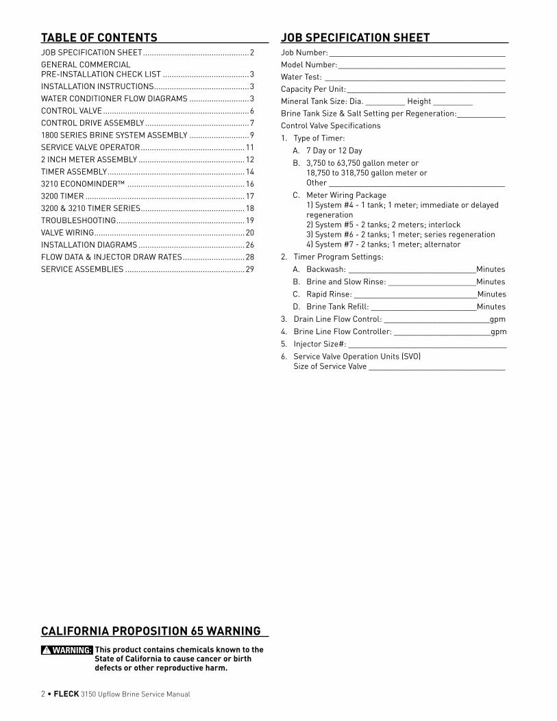
TABLE OF CONTENTSJOB SPECIFICATION SHEET ................................................2GENERAL COMMERCIAL PRE-INSTALLATION CHECK LIST .......................................3INSTALLATION INSTRUCTIONS ...........................................3WATER CONDITIONER FLOW DIAGRAMS ...........................3CONTROL VALVE ..................................................................6CONTROL DRIVE ASSEMBLY ...............................................71800 SERIES BRINE SYSTEM ASSEMBLY ...........................9SERVICE VALVE OPERATOR ...............................................112 INCH METER ASSEMBLY ................................................12TIMER ASSEMBLY ..............................................................143210 ECONOMINDER™ .....................................................163200 TIMER ........................................................................173200 & 3210 TIMER SERIES ...............................................18TROUBLESHOOTING ..........................................................19VALVE WIRING ....................................................................20INSTALLATION DIAGRAMS ................................................26FLOW DATA & INJECTOR DRAW RATES ............................28SERVICE ASSEMBLIES ......................................................29
JOB SPECIFICATION SHEETJob Number: ________________________________________Model Number: ______________________________________Water Test: _________________________________________Capacity Per Unit: ____________________________________Mineral Tank Size: Dia. _________ Height _________Brine Tank Size & Salt Setting per Regeneration: ___________Control Valve Specifications1. Type of Timer:
A. 7 Day or 12 DayB. 3,750 to 63,750 gallon meter or
18,750 to 318,750 gallon meter or Other ________________________________________
C. Meter Wiring Package 1) System #4 - 1 tank; 1 meter; immediate or delayed regeneration 2) System #5 - 2 tanks; 2 meters; interlock 3) System #6 - 2 tanks; 1 meter; series regeneration 4) System #7 - 2 tanks; 1 meter; alternator
2. Timer Program Settings:A. Backwash: _____________________________MinutesB. Brine and Slow Rinse: ____________________MinutesC. Rapid Rinse: ____________________________MinutesD. Brine Tank Refill: ________________________Minutes
3. Drain Line Flow Control: ________________________gpm4. Brine Line Flow Controller: ______________________gpm5. Injector Size#: ____________________________________6. Service Valve Operation Units (SVO)
Size of Service Valve _______________________________
CALIFORNIA PROPOSITION 65 WARNINGWARNING: This product contains chemicals known to the
State of California to cause cancer or birth defects or other reproductive harm.
2 • FLECK 3150 Upflow Brine Service Manual

GENERAL COMMERCIAL PRE-INSTALLATION CHECK LISTWater Pressure A minimum of 25 pounds of water pressure is required for regeneration valve to operate effectively.
Electrical Facilities A continuous 115 volt, 60 Hertz current supply is required. (Other voltages available.) Make certain the current supply is always hot and cannot be turned off with another switch.
Existing Plumbing Condition of existing plumbing should be free from lime and iron buildup. Piping that is built up heavily with lime and/or iron should be replaced. If piping is clogged with iron, a separate iron filter unit should be installed ahead of the water softener.
Location Of Softener And DrainThe softener should be located close to a drain.
By-Pass ValvesAlways provide for the installation of a by-pass valve.
CAUTION Water pressure is not to exceed 120 psi, water temperature is not to exceed 110°F, and the unit cannot be subjected to freezing conditions.
INSTALLATION INSTRUCTIONS1. Place the softener tank where you want to install the unit
making sure the unit is level and on a firm base. (Maximum 7 feet apart for twin units.)
2. All plumbing should be done in accordance with local plumbing codes. The pipe size for the drain line should be the same size as the drain line flow control connection. Water meters are to be installed on soft water outlets. Twin units with (1) one meter shall be installed on common soft water outlet of units.
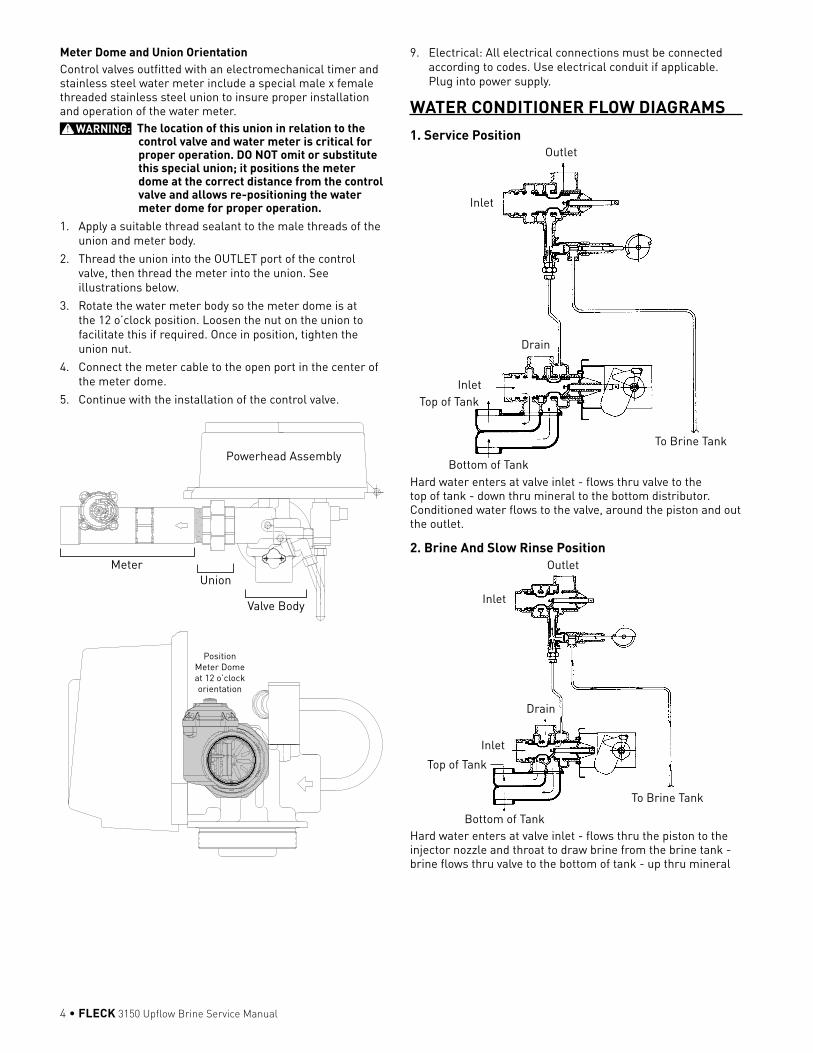
3. IMPORTANT: For valves equipped with electromechanical timers and stainless steel meters, refer to the Meter Dome and Union Orientation section.
4. Make sure that the floor is clean beneath the salt storage tank and that it is level.
5. Place approximately 1 inch of water above the grid plate (if used) in your salt tank. Salt may be placed in the unit at this time.
6. Place in by-pass position. Turn on the main water supply. Open a cold soft water tap nearby and let run a few minutes or until the system is free from foreign material (usually solder) that may have resulted from the installation.
7. Place the by-pass in service position.8. Manually index the softener control into “service” position
and let water flow into the mineral tank. When water flow stops, close inlet valve, place control in “brine and rinse” position to relieve head of air, then gradually open inlet valve to purge remaining air in tank Return control to “service” position.
FLECK 3150 Upflow Brine Service Manual • 3
9. Electrical: All electrical connections must be connected according to codes. Use electrical conduit if applicable. Plug into power supply.
WATER CONDITIONER FLOW DIAGRAMS1. Service Position
Outlet
Inlet
Inlet
Drain
Top of Tank
Bottom of Tank
To Brine Tank
Hard water enters at valve inlet - flows thru valve to the top of tank - down thru mineral to the bottom distributor. Conditioned water flows to the valve, around the piston and out the outlet.
2. Brine And Slow Rinse PositionOutlet
Inlet
Inlet
Drain
Top of Tank
Bottom of Tank
To Brine Tank
Hard water enters at valve inlet - flows thru the piston to the injector nozzle and throat to draw brine from the brine tank - brine flows thru valve to the bottom of tank - up thru mineral
Meter Dome and Union OrientationControl valves outfitted with an electromechanical timer and stainless steel water meter include a special male x female threaded stainless steel union to insure proper installation and operation of the water meter.
The location of this union in relation to the control valve and water meter is critical for proper operation. DO NOT omit or substitute this special union; it positions the meter dome at the correct distance from the control valve and allows re-positioning the water meter dome for proper operation.
1. Apply a suitable thread sealant to the male threads of the union and meter body.
2. Thread the union into the OUTLET port of the control valve, then thread the meter into the union. See illustrations below.
3. Rotate the water meter body so the meter dome is at the 12 o’clock position. Loosen the nut on the union to facilitate this if required. Once in position, tighten the union nut.
4. Connect the meter cable to the open port in the center of the meter dome.
5. Continue with the installation of the control valve.
PositionMeter Dome at 12 o’clockorientation
MeterUnion
Valve Body
Powerhead Assembly
4 • FLECK 3150 Upflow Brine Service Manual

to top of tank, around the piston and out the drain. Flow thru injectors continues for slow rinse for remainder of cycle. Hard water is also available at valve outlet.
3. Backwash PositionOutlet
Inlet
Inlet
Drain
Top of Tank
Bottom of Tank
To Brine Tank
Hard water enters at valve inlet - flows thru piston to the bottom of tank - up thru mineral to top of tank, around the piston and out the drain. Hard water is also available at valve outlet.
4. Rapid Rinse PositionOutlet
Inlet
Inlet
Drain
Top of Tank
Bottom of Tank
To Brine Tank
Hard water enters at valve inlet - flows thru valve to the top
bottom of tank - down thru mineral to bottom distributor - back to top of tank, around the piston and out the drain. Hard water is also available at valve outlet.
5. Brine Tank Refill PositionOutlet
Inlet
InletDrain
Top of Tank
Bottom of TankTo Brine Tank
Hard water enters at valve inlet - flows thru valve to the top of tank - down thru mineral to the bottom distributor. Conditioned water flows up to valve outlet and thru the throat and nozzle to fill brine tank.
WATER CONDITIONER FLOW DIAGRAMS CONTINUED
FLECK 3150 Upflow Brine Service Manual • 5
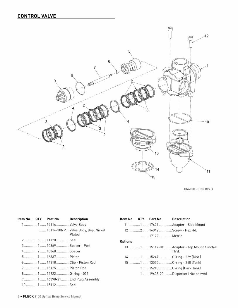
CONTROL VALVE
Item No. QTY Part No. Description 1 ..............1 ...... 15114 ..............Valve Body ....... 15114-30NP....Valve Body, Bsp, Nickel
Plated 2 ..............8 ...... 11720 ..............Seal 3 ..............5 ...... 10369 ..............Spacer - Port 4 ..............2 ...... 10368 ..............Spacer 5 ..............1 ...... 16337 ..............Piston 6 ..............1 ...... 14818 ..............Clip - Piston Rod 7 ..............1 ...... 15125 ..............Piston Rod 8 ..............1 ...... 14922 ..............O-ring - 035 9 ..............1 ...... 16398-21 .........End Plug Assembly 10 ............1 ...... 15112 ..............Seal
11 ............1 ...... 17407 ..............Adapter - Side Mount 12 ............2 ...... 16042 ..............Screw - Hex Hd. ....... 17122 ..............MetricOptions 13 ............1 ...... 15117-01 .........Adapter - Top Mount 4 inch-8
Th’d. 14 ............1 ...... 15247 ..............O-ring - 229 (Dist.) 15 ............1 ...... 13575 ..............O-ring - 240 (Tank) 1 ...... 15210 ..............O-ring (Park Tank) 1 ...... 19608-20 .........Disperser (Not shown)
Item No. QTY Part No. Description
BR61500-3150 Rev B
11
10
1
12
3
4
3
2
2
3
42
2
5
67
89
13
14
15
6 • FLECK 3150 Upflow Brine Service Manual

CONTROL DRIVE ASSEMBLY
123456789
1011
1314
1516
1718
19 2021
2223 24
2526
27
28B
2930
31
3233
3435
363738
394041
42
43
28A
16
FLECK 3150 Upflow Brine Service Manual • 7
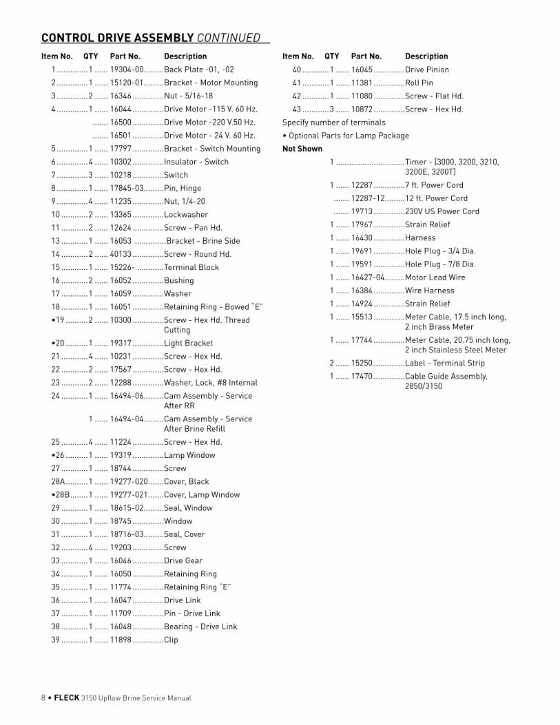
Item No. QTY Part No. Description 1 ..............1 ...... 19304-00 .........Back Plate -01, -02 2 ..............1 ...... 15120-01 .........Bracket - Motor Mounting 3 ..............2 ...... 16346 ..............Nut - 5/16-18 4 ..............1 ...... 16044 ..............Drive Motor -115 V. 60 Hz. ....... 16500 ..............Drive Motor -220 V.50 Hz. ....... 16501 ..............Drive Motor - 24 V. 60 Hz. 5 ..............1 ...... 17797 ..............Bracket - Switch Mounting 6 ..............4 ...... 10302 ..............Insulator - Switch 7 ..............3 ...... 10218 ..............Switch 8 ..............1 ...... 17845-03 .........Pin, Hinge 9 ..............4 ...... 11235 ..............Nut, 1/4-20 10 ............2 ...... 13365 ..............Lockwasher 11 ............2 ...... 12624 ..............Screw - Pan Hd. 13 ............1 ...... 16053 ..............Bracket - Brine Side 14 ............2 ...... 40133 ..............Screw - Round Hd. 15 ............1 ...... 15226- ............Terminal Block 16 ............2 ...... 16052 ..............Bushing 17 ............1 ...... 16059 ..............Washer 18 ............1 ...... 16051 ..............Retaining Ring - Bowed “E” •19 ..........2 ...... 10300 ..............Screw - Hex Hd. Thread
Cutting •20 ..........1 ...... 19317 ..............Light Bracket 21 ............4 ...... 10231 ..............Screw - Hex Hd. 22 ............2 ...... 17567 ..............Screw - Hex Hd. 23 ............2 ...... 12288 ..............Washer, Lock, #8 Internal 24 ............1 ...... 16494-06 .........Cam Assembly - Service
After RR 1 ...... 16494-04 .........Cam Assembly - Service
After Brine Refill 25 ............4 ...... 11224 ..............Screw - Hex Hd. •26 ..........1 ...... 19319 ..............Lamp Window 27 ............1 ...... 18744 ..............Screw 28A ..........1 ...... 19277-020 .......Cover, Black •28B ........1 ...... 19277-021 .......Cover, Lamp Window 29 ............1 ...... 18615-02 .........Seal, Window 30 ............1 ...... 18745 ..............Window 31 ............1 ...... 18716-03 .........Seal, Cover 32 ............4 ...... 19203 ..............Screw 33 ............1 ...... 16046 ..............Drive Gear 34 ............1 ...... 16050 ..............Retaining Ring 35 ............1 ...... 11774 ..............Retaining Ring “E” 36 ............1 ...... 16047 ..............Drive Link 37 ............1 ...... 11709 ..............Pin - Drive Link 38 ............1 ...... 16048 ..............Bearing - Drive Link 39 ............1 ...... 11898 ..............Clip
40 ............1 ...... 16045 ..............Drive Pinion 41 ............1 ...... 11381 ..............RolI Pin 42 ............1 ...... 11080 ..............Screw - Flat Hd. 43 ............3 ...... 10872 ..............Screw - Hex Hd.Specify number of terminals • Optional Parts for Lamp PackageNot Shown 1 ...............................Timer - [3000, 3200, 3210,
3200E, 3200T] 1 ...... 12287 ..............7 ft. Power Cord ....... 12287-12 .........12 ft. Power Cord ....... 19713 ..............230V US Power Cord 1 ...... 17967 ..............Strain Relief 1 ...... 16430 ..............Harness 1 ...... 19691 ..............Hole Plug - 3/4 Dia. 1 ...... 19591 ..............Hole Plug - 7/8 Dia. 1 ...... 16427-04 .........Motor Lead Wire 1 ...... 16384 ..............Wire Harness 1 ...... 14924 ..............Strain Relief 1 ...... 15513 ..............Meter Cable, 17.5 inch long,
2 inch Brass Meter 1 ...... 17744 ..............Meter Cable, 20.75 inch long,
2 inch Stainless Steel Meter 2 ...... 15250 ..............Label - Terminal Strip 1 ...... 17470 ..............Cable Guide Assembly,
2850/3150
Item No. QTY Part No. Description
CONTROL DRIVE ASSEMBLY CONTINUED
8 • FLECK 3150 Upflow Brine Service Manual
1
2
3
4
5
6
7
8
910
1112
13
1415
16
17
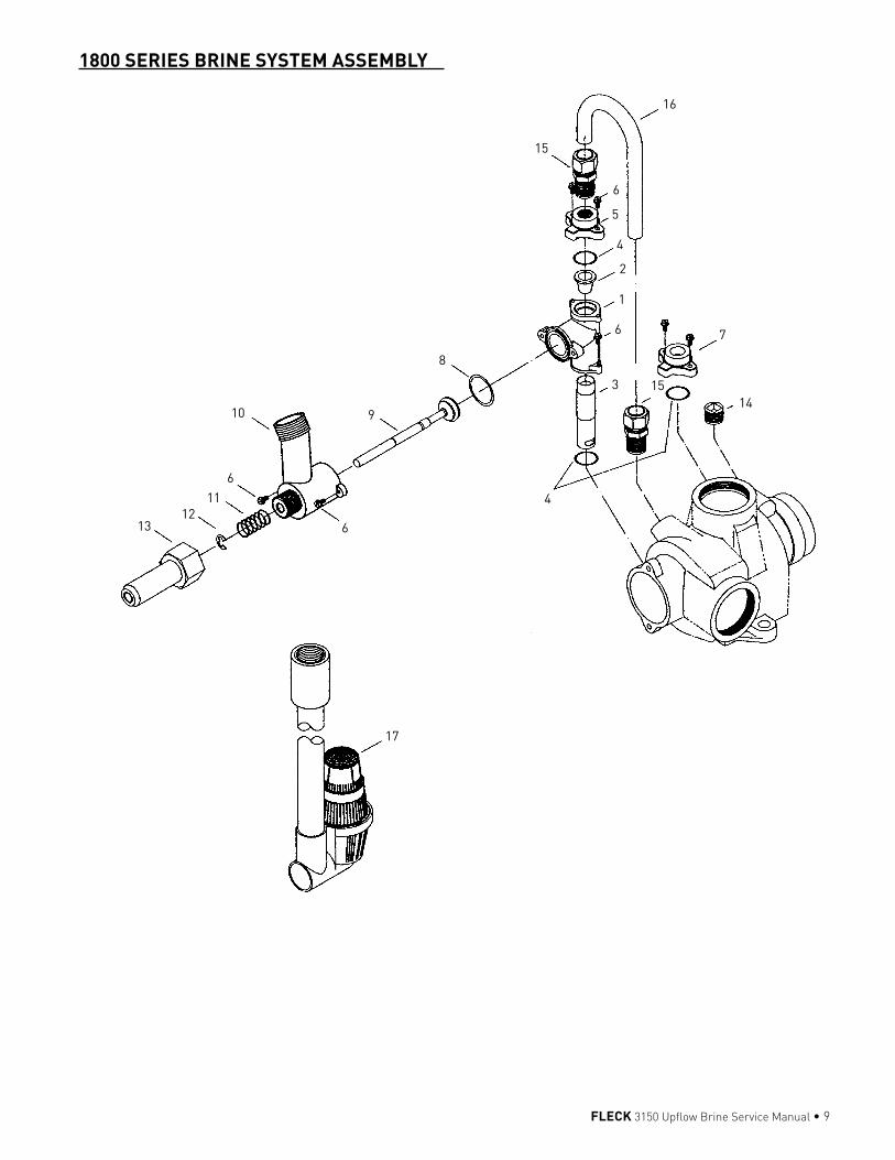
1800 SERIES BRINE SYSTEM ASSEMBLY
6
6
4
6
15
FLECK 3150 Upflow Brine Service Manual • 9

1800 SERIES BRINE SYSTEM ASSEMBLY CONTINUEDItem No. QTY Part No. Description 1 ....................... 16340-01 .........Injector Body 2 ..............1 ...... 15128- ............Injector Nozzle 3 ..............1 ...... 15127- ............Injector Throat 4 ..............3 ...... 15246 ..............O-ring -116 5 ..............1 ...... 16341-01 .........Injector Cover 6 ..............6 ...... 12473 ..............Screw - Hex Hd. 7 ..............1 ...... 16341-02 .........Cover 8 ..............1 ...... 16605 ..............Retainer Plate 9 ..............2 ...... 13303 ..............O-ring - 021 10 ............1 ...... 16596 ..............Nut - Q.C. 11 ............1 ...... 16203-01 .........Connector - Brine Valve 12 ............1 ...... 16497 ..............Brine Stem Assembly 13 ............1 ...... 15241 ..............Brine Valve Body 14 ............1 ...... 11772 ..............Spring 15 ............1 ...... 11774 ..............Retaining Ring 16 ............1 ...... 16498-01 .........Stem Guide Assembly 17 ............1 ...... 11912 ..............Fitting - Brine LineNot Shown 1 ...... 11183 ..............O-ring - 017 1 ...... 11180 ..............Screw - Round Hd. 1 ...... 16387 ..............Pipe Plug - 1/2 NPT 2 ...... 16388 ..............Tube Fitting - Straight 1 ...... 16491 ..............Brine Tube - Not Shown 1 ...... 60007 ..............Commercial Air Check 1 ...............................Flow Control - Specify Flow
Rate Specify size Option Without Brine Valve 1 ...... 16620 ..............Fitting - Brine Tank 2 ...... 10231 ..............Screw - Brine Side Bracket 2 ...... 11235 ..............Nut - Brine Side Bracket 1 ...... 13303 ..............O-ring - 021 ....... Delete: Items 9 thru 19Injector Throat Size Color ....... 15127-05 .........#5 Red ....... 15127-06 .........#6 White ....... 15127-07 .........#7 Blue ....... 15127-08 .........#8 Yellow ....... 15127-09 .........#9 Green ....... 15127-10 .........#10 BlackInjector Nozzle ....... 15128-05 ......... #5 Red ....... 15128-06 ......... #6 White ....... 15128-07 .........#7 Blue ....... 15128-08 .........#8 Yellow ....... 15128-09 .........#9 Green ....... 15128-10 .........#10 Black10 • FLECK 3150 Upflow Brine Service Manual

1
2
3
45
67
8
910
11
12
13
1415
SERVICE VALVE OPERATOR
Item No. QTY Part No. Description 1 ..............1 ...... 15074 ..............Valve Body 2 ..............1 ...... 16065 ..............Stem 3 ..............1 ...... 10141 ..............O-ring - 010 4 ..............2 ...... 14835 ..............Seal 5 ..............1 ...... 14834 ..............Spacer 6 ..............1 ...... 16509 ..............End Plug 7 ..............1 ...... 14516 ..............O-ring - 015 8 ..............1 ...... 15965 ..............Fitting - 1/4 Tube 9 ..............1 ...... 10249 ..............Spring 10 ............1 ...... 10250 ..............Retaining Ring 11 ............1 ...... 16498-02 .........Stem Guide Assembly 12 ............3 ...... 10332 ..............Insert 13 ............3 ...... 10330 ..............Ferrule 14 ............3 ...... 10329 ..............Nut 15 ............1 ...... 16503 ..............Tube FittingNot Shown 1 ...... 16511 ..............SVO Tube
12
13
14
4
12
13
14
FLECK 3150 Upflow Brine Service Manual • 11

12 • FLECK 3150 Upflow Brine Service Manual
2-INCH BRASS METER ASSEMBLY
Item No. QTY Part No. Description 1 ..............1 ...... 14456 ..............Body, Meter, 2-inch ....... 14456-20 .........Body, Meter, 2-inch, BSP,
Metric 2 ..............1 ...... 15532 ..............Seat, Impeller Shaft, Hex 3 ..............1 ...... 15432 ..............Shaft 5 ..............1 ...... 15374 ..............Impeller Assy, 2-inch
Meter 6 ..............1 ...... 13847 ..............O-ring, -137, Std/560CD,
Meter 7A ............1 ...... 14038 ..............Meter Cap Assembly, Std,
Plastic 7B ............1 ...... 15150 ..............Meter Cap Assembly,
3/4-inch to 2-inch, Ext Plastic, Pdl
8 ..............4 ...... 12112 ..............Screw, Hex Hd Mach, 10-24 x 1/2 18-8 Stainless Steel
....... 15886 ..............Screw, Hex Hd, M5 x 12 SS, Metric
9 ..............1 ...... 14679 ..............O-ring, -227, Meter 10 ............1 ...... 14568 ..............Fitting, Nipple, 2-inch ....... 14568-10 .........Fitting, Nipple, 2-inch BSP,
Brass
13
14
11 ............1 ...... 14680 ..............Flow Straightener 12 ............1 ...... 14569 ..............Nut, 2900 Meter 13 ..............................................Meter Assy, 2-inch Inline,
NPT, STD, Brass, Paddlewheel ................................Meter Assy, 2-inch Inline,
BSP, STD, Brass, Paddlewheel 14 ..............................................Meter Assy, 2-inch Inline,
NPT, EXT, Brass Paddlewheel ................................Meter Assy, 2-inch Inline,
BSP, EXT, Brass, PaddlewheelNot Shown ....... 61439 ..............Meter Sleeve w/O-rings, 1-1/2
inch
Item No. QTY Part No. Description
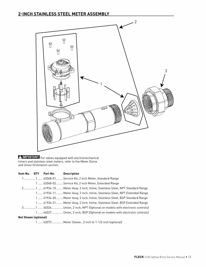
2-INCH STAINLESS STEEL METER ASSEMBLY
Item No. QTY Part No. Description 1 ..............1 ...... 62048-01 .........Service Kit, 2 inch Meter, Standard Range 1 ...... 62048-02 .........Service Kit, 2 inch Meter, Extended Range 2 ..............1 ...... 61934-10 .........Meter Assy, 2 inch, Inline, Stainless Steel, NPT Standard Range 1 ...... 61934-11 .........Meter Assy, 2 inch, Inline, Stainless Steel, NPT Extended Range 1 ...... 61934-20 .........Meter Assy, 2 inch, Inline, Stainless Steel, BSP Standard Range 1 ...... 61934-21 .........Meter Assy, 2 inch, Inline, Stainless Steel, BSP Extended Range 3 ..............1 ...... 44026 ..............Union, 2 inch, NPT (Optional on models with electronic controls) 1 ...... 44027 ..............Union, 2 inch, BSP (Optional on models with electronic controls)Not Shown (optional) 1 ...... 62073 ..............Meter Sleeve , 2 inch to 1-1/2 inch (optional)
1
3
2
IMPORTANT: For valves equipped with electromechanical timers and stainless steel meters, refer to the Meter Dome and Union Orientation section.
FLECK 3150 Upflow Brine Service Manual • 13
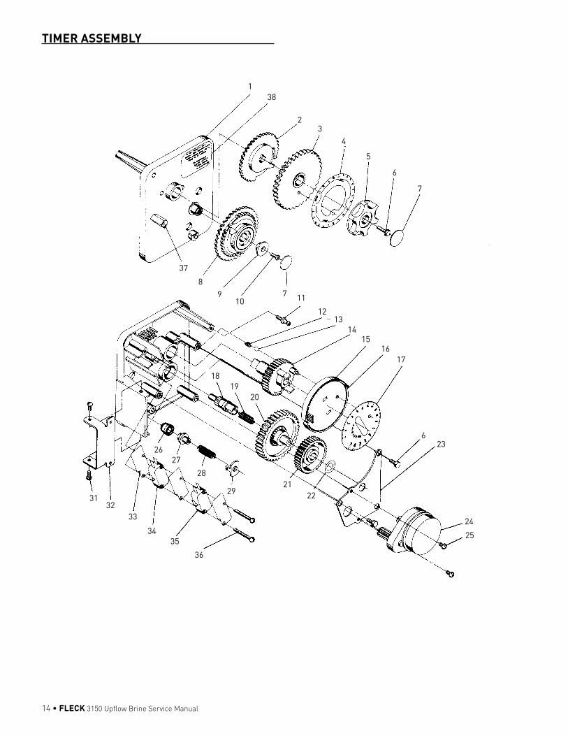
1
23
4
5
6
78
910 11
1213
1415
1617
1819
20
2122
23
2425
26
2827
2931
3233
3435
36
37
38
TIMER ASSEMBLY
6
7
14 • FLECK 3150 Upflow Brine Service Manual
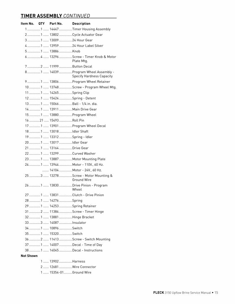
Item No. QTY Part No. Description 1 ..............1 ...... 14447 ..............Timer Housing Assembly 2 ..............1 ...... 13802 ..............Cycle Actuator Gear 3 ..............1 ...... 13009 ..............24 Hour Gear 4 ..............1 ...... 13959 ..............24 Hour Label Silver 5 ..............1 ...... 13886 ..............Knob 6 ..............4 ...... 13296 ..............Screw - Timer Knob & Motor
Plate Mtg. 7 ..............2 ...... 11999 ..............Button Decal 8 ..............1 ...... 14039 ..............Program Wheel Assembly -
Specify Hardness Capacity 9 ..............1 ...... 13806 ..............Program Wheel Retainer 10 ............1 ...... 13748 ..............Screw - Program Wheel Mtg. 11 ............1 ...... 14265 ..............Spring Clip 12 ............1 ...... 15424 ..............Spring - Detent 13 ............1 ...... 15066 ..............Ball - 1/4 in. dia. 14 ............1 ...... 13911 ..............Main Drive Gear 15 ............1 ...... 13880 ..............Program Wheel 16 ...........21 ..... 15493 ..............Roll Pin 17 ............1 ...... 13901 ..............Program Wheel Decal 18 ............1 ...... 13018 ..............Idler Shaft 19 ............1 ...... 13312 ..............Spring - Idler 20 ............1 ...... 13017 ..............Idler Gear 21 ............1 ...... 13164 ..............Drive Gear 22 ............1 ...... 13299 ..............Curved Washer 23 ............1 ...... 13887 ..............Motor Mounting Plate 24 ............1 ...... 13944 ..............Motor - 110V., 60 Hz. ....... 14104 ..............Motor - 24V., 60 Hz. 25 ............3 ...... 13278 ..............Screw - Motor Mounting &
Ground Wire 26 ............1 ...... 13830 ..............Drive Pinion - Program
Wheel 27 ............1 ...... 13831 ..............Clutch - Drive Pinion 28 ............1 ...... 14276 ..............Spring 29 ............1 ...... 14253 ..............Spring Retainer 31 ............2 ...... 11384 ..............Screw - Timer Hinge 32 ............1 ...... 13881 ..............Hinge Bracket 33 ............3 ...... 14087 ..............Insulator 34 ............1 ...... 10896 ..............Switch 35 ............1 ...... 15320 ..............Switch 36 ............2 ...... 11413 ..............Screw - Switch Mounting 37 ............1 ...... 14007 ..............Decal - Time of Day 38 ............1 ...... 14045 ..............Decal - InstructionsNot Shown 1 ...... 13902 ..............Harness 2 ...... 12681 ..............Wire Connector 1 ...... 15354-01 .........Ground Wire
TIMER ASSEMBLY CONTINUED
FLECK 3150 Upflow Brine Service Manual • 15
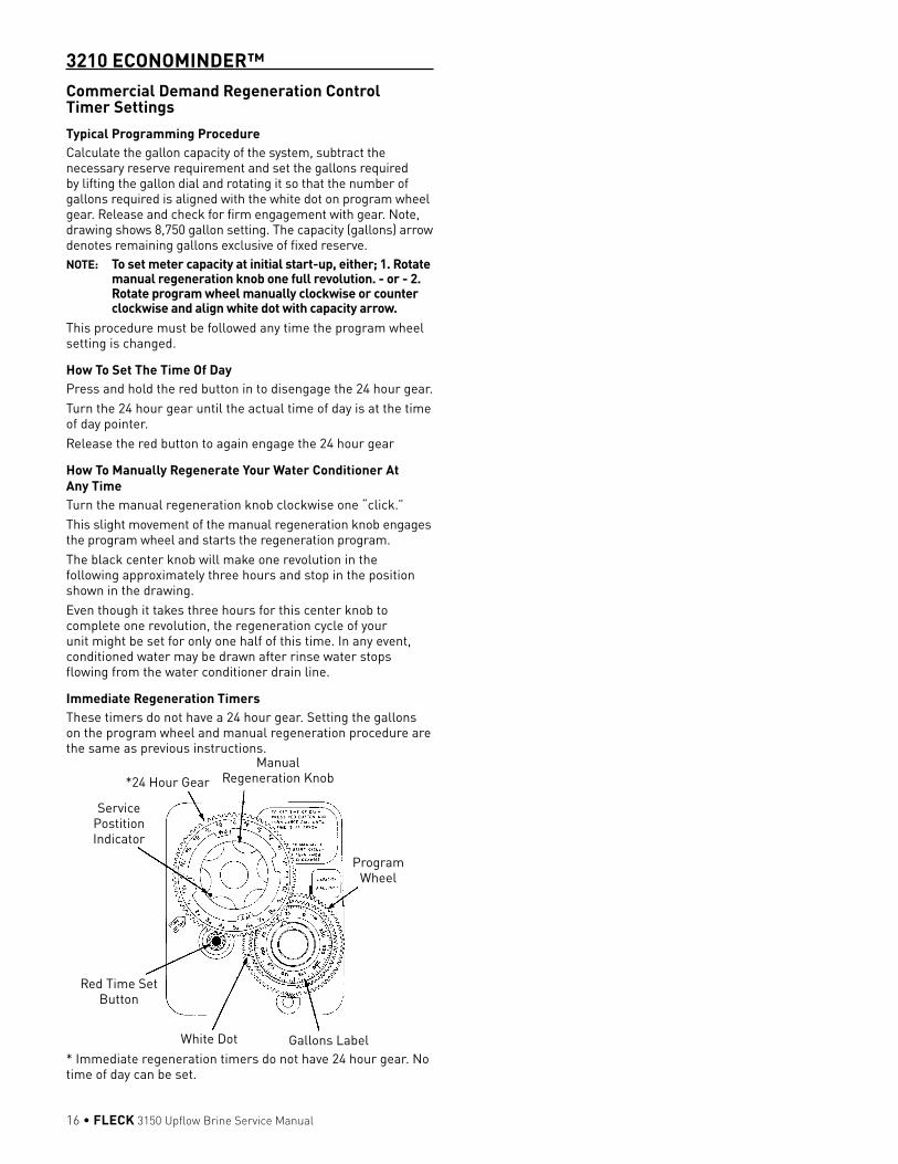
3210 ECONOMINDER™ Commercial Demand Regeneration Control Timer SettingsTypical Programming ProcedureCalculate the gallon capacity of the system, subtract the necessary reserve requirement and set the gallons required by lifting the gallon dial and rotating it so that the number of gallons required is aligned with the white dot on program wheel gear. Release and check for firm engagement with gear. Note, drawing shows 8,750 gallon setting. The capacity (gallons) arrow denotes remaining gallons exclusive of fixed reserve.NOTE: To set meter capacity at initial start-up, either; 1. Rotate
manual regeneration knob one full revolution. - or - 2. Rotate program wheel manually clockwise or counter clockwise and align white dot with capacity arrow.
This procedure must be followed any time the program wheel setting is changed.
How To Set The Time Of DayPress and hold the red button in to disengage the 24 hour gear.Turn the 24 hour gear until the actual time of day is at the time of day pointer.Release the red button to again engage the 24 hour gear
How To Manually Regenerate Your Water Conditioner At Any TimeTurn the manual regeneration knob clockwise one “click.”This slight movement of the manual regeneration knob engages the program wheel and starts the regeneration program.The black center knob will make one revolution in the following approximately three hours and stop in the position shown in the drawing.Even though it takes three hours for this center knob to complete one revolution, the regeneration cycle of your unit might be set for only one half of this time. In any event, conditioned water may be drawn after rinse water stops flowing from the water conditioner drain line.
Immediate Regeneration TimersThese timers do not have a 24 hour gear. Setting the gallons on the program wheel and manual regeneration procedure are the same as previous instructions.
*24 Hour GearManual
Regeneration Knob
Program Wheel
White Dot
Red Time Set Button
Gallons Label
Service Postition Indicator
* Immediate regeneration timers do not have 24 hour gear. No time of day can be set.
16 • FLECK 3150 Upflow Brine Service Manual
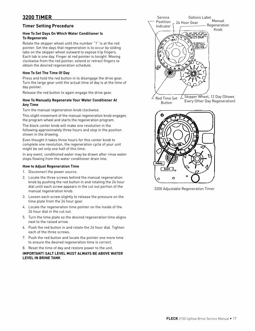
3200 TIMERTimer Setting ProcedureHow To Set Days On Which Water Conditioner Is To RegenerateRotate the skipper wheel until the number “1” is at the red pointer. Set the days that regeneration is to occur by sliding tabs on the skipper wheel outward to expose trip fingers. Each tab is one day. Finger at red pointer is tonight. Moving clockwise from the red pointer, extend or retract fingers to obtain the desired regeneration schedule.
How To Set The Time Of DayPress and hold the red button in to disengage the drive gear. Turn the large gear until the actual time of day is at the time of day pointer.Release the red button to again engage the drive gear.
How To Manually Regenerate Your Water Conditioner At Any TimeTurn the manual regeneration knob clockwise.This slight movement of the manual regeneration knob engages the program wheel and starts the regeneration program.The black center knob will make one revolution in the following approximately three hours and stop in the position shown in the drawing.Even thought it takes three hours for this center knob to complete one revolution, the regeneration cycle of your unit might be set only one half of this time.In any event, conditioned water may be drawn after rinse water stops flowing from the water conditioner drain line.
How to Adjust Regeneration Time1. Disconnect the power source.2. Locate the three screws behind the manual regeneration
knob by pushing the red button in and rotating the 24 hour dial until each screw appears in the cut out portion of the manual regeneration knob.
3. Loosen each screw slightly to release the pressure on the time plate from the 24 hour gear.
4. Locate the regeneration time pointer on the inside of the 24 hour dial in the cut out.
5. Turn the time plate so the desired regeneration time aligns next to the raised arrow.
6. Push the red button in and rotate the 24 hour dial. Tighten each of the three screws.
7. Push the red button and locate the pointer one more time to ensure the desired regeneration time is correct.
8. Reset the time of day and restore power to the unit.IMPORTANT! SALT LEVEL MUST ALWAYS BE ABOVE WATER LEVEL IN BRINE TANK
24 Hour Gear Manual Regeneration
Knob
Skipper Wheel, 12 Day (Shows Every Other Day Regeneration)
Red Time Set Button
Gallons LabelService Postition Indicator
3200 Adjustable Regeneration Timer
FLECK 3150 Upflow Brine Service Manual • 17
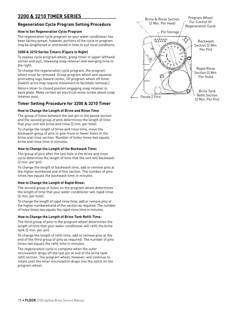
3200 & 3210 TIMER SERIESRegeneration Cycle Program Setting ProcedureHow to Set Regeneration Cycle ProgramThe regeneration cycle program on your water conditioner has been factory preset, however, portions of the cycle or program may be lengthened or shortened in time to suit local conditions.
3200 & 3210 SerIes Timers (Figure to Right)To expose cycle program wheel, grasp timer in upper lefthand corner and pull, releasing snap retainer and swinging time to the right.To change the regeneration cycle program, the program wheel must be removed. Grasp program wheel and squeeze protruding lugs toward center, lift program wheel off timer. (Switch arms may require movement to facilitate removal.)Return timer to closed position engaging snap retainer in back plate. Make certain all electrical wires locate above snap retainer post.
Timer Setting Procedure for 3200 & 3210 TimerHow to Change the Length of Brine and Rinse TimeThe group of holes between the last pin in the pause section and the second group of pins determines the length of time that your unit will brine and rinse (2 min. per hole).To change the length of brine and rinse time, move the backwash group of pins to give more or fewer holes in the brine and rinse section. Number of holes times two equals brine and rinse time in minutes.
How to Change the Length of the Backwash Time:The group of pins after the last hole in the brine and rinse cycle determine the length of time that the unit will backwash (2 min. per pin).To change the length of backwash time, add or remove pins at the higher numbered end of this section. The number of pins times two equals the backwash time in minutes.
How to Change the Length of Rapid Rinse:The second group of holes on the program wheel determines the length of time that your water conditioner will rapid rinse (2 min. per hole).To change the length of rapid rinse time, add or remove pins at the higher numbered end of this section as required. The number of holes times two equals the rapid rinse time in minutes.
How to Change the Length of Brine Tank Refill Time:The third group of pins in the program wheel determines the length of time that your water conditioner will refill the brine tank (2 min. per pin).To change the length of refill time, add or remove pins at the end of the third group of pins as required. The number of pins times two equals the refill time in minutes.The regeneration cycle is complete when the outer microswitch drops off the last pin at end of the brine tank refill section. The program wheel, however, will continue to rotate until the inner microswitch drops into the notch on the program wheel.
Brine & Rinse Section (2 Min. Per Hole)
Program Wheel For Control Of
Regeneration Cycle
Backwash Section (2 Min.
Per Pin)
Pin Storage
Rapid Rinse Section (2 Min.
Per Hole)
Brine Tank Refill Section
(2 Min. Per Pin)Pause 2 Pins
18 • FLECK 3150 Upflow Brine Service Manual
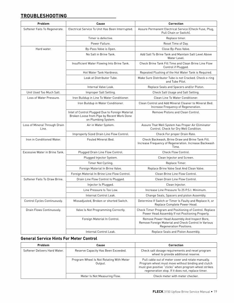
TROUBLESHOOTINGProblem Cause Correction
Softener Fails To Regenerate. Electrical Service To Unit Has Been Interrupted. Assure Permanent Electrical Service (Check Fuse, Plug, Pull Chain or Switch).
Timer is defective. Replace timer.
Power Failure. Reset Time of Day.
Hard water. By-Pass Valve is Open. Close By-Pass Valve.
No Salt in Brine Tank. Add Salt To Brine Tank and Maintain Salt Level Above Water Level.
Insufficient Water Flowing Into Brine Tank. Check Brine Tank Fill Time and Clean Brine Line Flow Control if Plugged.
Hot Water Tank Hardness. Repeated Flushing of the Hot Water Tank is Required.
Leak at Distributor Tube. Make Sure Distributor Tube is not Cracked. Check o-ring and Tube Pilot.
Internal Valve Leak. Replace Seals and Spacers and/or Piston.
Unit Used Too Much Salt. Improper Salt Setting. Check Salt Usage and Salt Setting.
Loss of Water Pressure. Iron Buildup in Line To Water Conditioner. Clean Line To Water Conditioner.
Iron Buildup in Water Conditioner. Clean Control and Add Mineral Cleaner to Mineral Bed. Increase Frequency of Regeneration.
Inlet of Control Plugged Due to Foreign Material Broken Loose from Pipe by Recent Work Done
on Plumbing System.
Remove Pistons and Clean Control.
Loss of Mineral Through Drain Line.
Air in Water System. Assure That Well System has Proper Air Eliminator Control. Check for Dry Well Condition.
Improperly Sized Drain Line Flow Control. Check For proper Drain Rate.
Iron in Conditioned Water. Fouled Mineral Bed. Check Backwash, Brine Draw and Brine Tank Fill. Increase Frequency of Regeneration. Increase Backwash
Time.
Excessive Water in Brine Tank. Plugged Drain Line Flow Control. Check Flow Control.
Plugged Injector System. Clean Injector and Screen.
Timer Not Cycling. Replace Timer.
Foreign Material In Brine Valve. Replace Brine Valve Seat And Clean Valve.
Foreign Material In Brine Line Flow Control. Clean Brine Line Flow Control.
Softener Fails To Draw Brine. Drain Line Flow Control Is Plugged. Clean Drain Line Flow Control.
Injector Is Plugged. Clean Injector.
Line Pressure Is Too Low. Increase Line Pressure To 25 P.S.I. Minimum.
Internal Control Leak. Change Seals, Spacers and piston Assembly.
Control Cycles Continuously. Missadjusted, Broken or shorted Switch. Determine If Switch or Timer Is Faulty and Replace It, or Replace Complete Power Head.
Drain Flows Continuously. Valve Is Not Programming Correctly. Check Timer Program and Positioning of Control. Replace Power Head Assembly If not Positioning Properly.
Foreign Material In Control. Remove Power Head Assembly And Inspect Bore, Remove Foreign Material and Check Control In Various
Regeneration Positions.
Internal Control Leak. Replace Seals and Piston Assembly.
General Service Hints For Meter ControlProblem Cause Correction
Softener Delivers Hard Water. Reserve Capacity Has Been Exceeded. Check salt dosage requirements and reset program wheel to provide additional reserve.
Program Wheel Is Not Rotating With Meter Output.
Pull cable out of meter cover and rotate manually. Program wheel must move without binding and clutch
must give positive “clicks” when program wheel strikes regeneration stop. If it does not, replace timer.
Meter Is Not Measuring Flow. Check meter with meter checker.
FLECK 3150 Upflow Brine Service Manual • 19
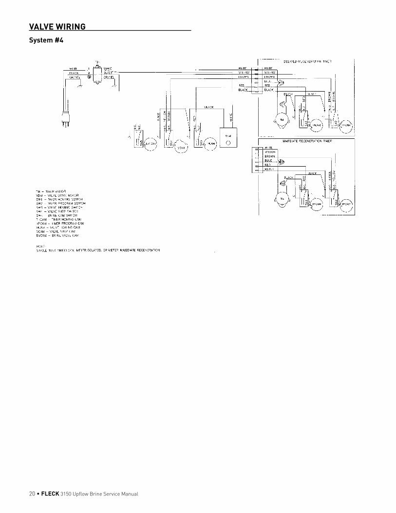
VALVE WIRINGSystem #4
20 • FLECK 3150 Upflow Brine Service Manual
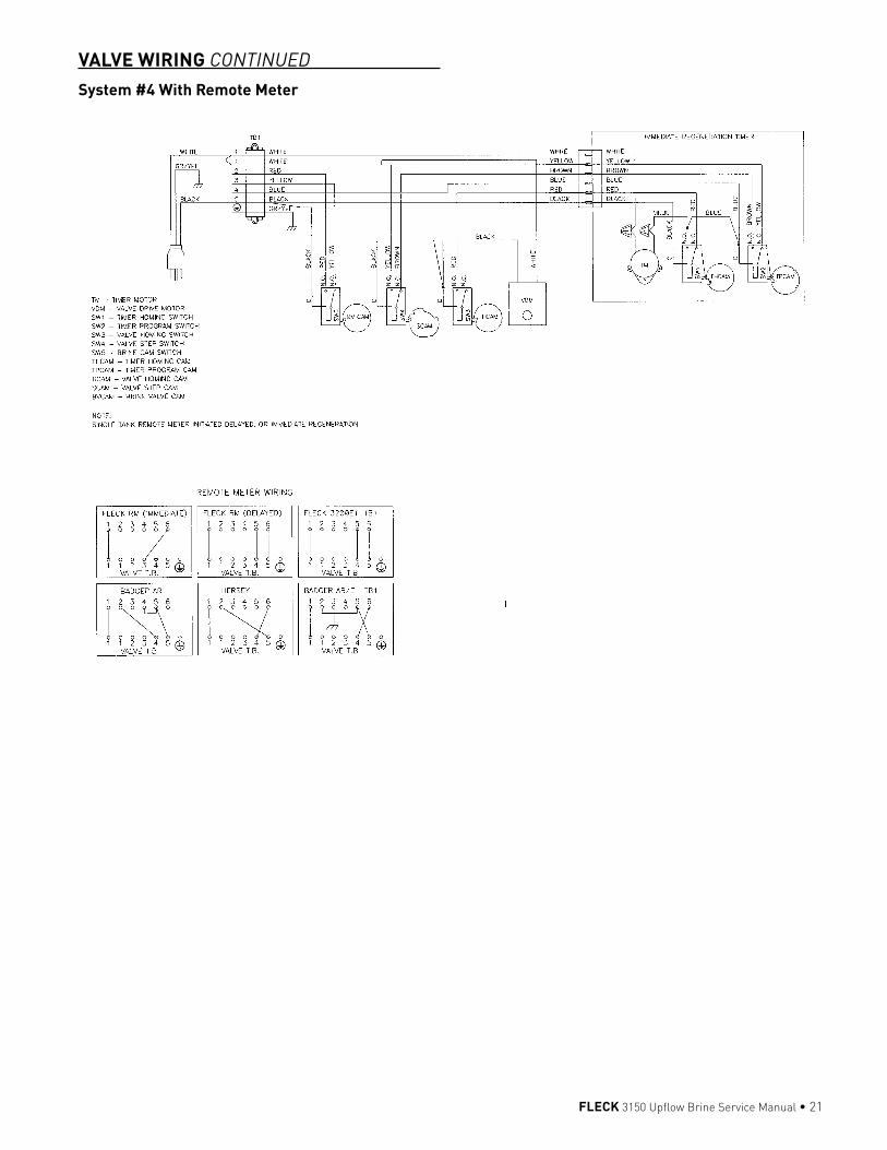
VALVE WIRING CONTINUEDSystem #4 With Remote Meter
FLECK 3150 Upflow Brine Service Manual • 21

VALVE WIRING CONTINUEDSystem #5
22 • FLECK 3150 Upflow Brine Service Manual
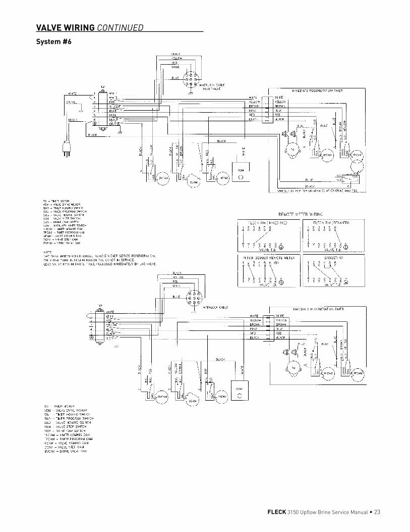
VALVE WIRING CONTINUEDSystem #6
FLECK 3150 Upflow Brine Service Manual • 23

VALVE WIRING CONTINUED24V/120V System #7
24 • FLECK 3150 Upflow Brine Service Manual

VALVE WIRING CONTINUED230V System #7
FLECK 3150 Upflow Brine Service Manual • 25

INSTALLATION DIAGRAMSSystem #4 - Typical Single Tank Installation with Optional Meter
System #5 Interlock - Typical Twin Tank Installation with Optional Meter Interlock and No Hard Water Bypass
26 • FLECK 3150 Upflow Brine Service Manual

INSTALLATION DIAGRAMS CONTINUEDSystem #6 - Twin Series Regeneration Installation with a Remote Meter
System #7 - Twin Alternator Installation with a Remote Meter
FLECK 3150 Upflow Brine Service Manual • 27
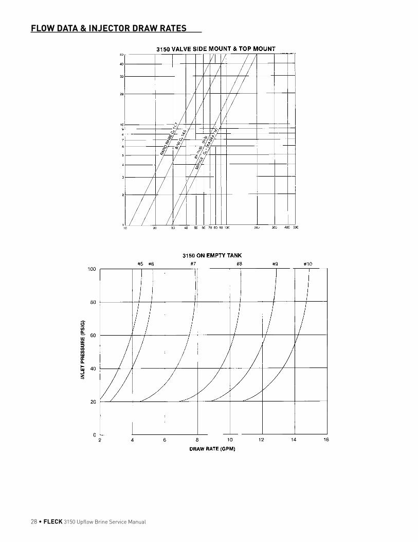
FLOW DATA & INJECTOR DRAW RATES
28 • FLECK 3150 Upflow Brine Service Manual

SERVICE ASSEMBLIES 60036-02 1800 Brine Valve..............11180 ...................... Screw - Round Hd.1 ............11183 ...................... O-ring - 0171 ............16596 ...................... Nut - Q.C.1 ............11772 ...................... Spring1 ............11774 ...................... Retaining Ring1 ............11912 ...................... Fitting - Brine Line2 ............13303 ...................... O-ring - 0211 ............15241 ...................... Brine Valve Body1 ............16203-01 ................. Connector - Brine Valve1 ............16497 ...................... Brine Stem Assembly1 ............16498-01 ................. Stem Guide Assembly1 ............16605 ...................... Retainer Plate
60277 1800 Injector Assembly4 ............12473 ...................... Screw - Hex Hd.1 ............15127 ...................... Injector Throat - Specify Size1 ............15128 ...................... Injector Nozzle - Specify Size2 ............15246 ...................... O-ring - 1161 ............16340 ...................... Injector Body1 ............16341-01 ................. Injector Cover
60106-10 3150 Piston Assembly
1 ............14818 ...................... Clip Piston Rod1 ............14922 ...................... O-ring - 0351 ............16337 ...................... Piston1 ............15125 ...................... Piston Rod1 ............16398-21 ................. End Plug Assembly - Gray
60131 31505 Seal Kit2 ............10368 ...................... Spacer5 ............10369 ...................... Spacer - Port8 ............11720 ...................... Seal
60057-01 3900 Upper Drive Motor Assembly - 115 V.
4 ............10302 ...................... Insulator - Switch3 ............10872 ...................... Screw - Hex Hd.1 ............1080 ........................ Screw - Flat Hd.3 ............1247 ........................ Switch2 ............12660 ...................... Nut 10-242 ............13314 ...................... Screw - Hex Hd.1 ............15120 ...................... Bracket - Motor Mounting1 ............16044 ...................... Drive Motor - 115 V.1 ............16052 ...................... Bushing1 ............16054 ...................... Bracket - Switch Mounting2 ............16055 ...................... Stand-Off2 ............116056..................... Screw - Pan Hd.2 ............116131..................... Spacer
60150-3150 3150 SVO Assembly For Parts Breakdown
60393 2 Meter Assembly - Std. Range For Parts Breakdown
60394 2 Meter Assembly - Ext. Range
61934-10 Meter Assy, 2 inch SS NPT Std 61934-11 Meter Assy, 2 inch SS NPT Ext 61934-20 Meter Assy, 2 inch SS BSP Std 61934-21 Meter Assy, 2 inch SS BSP Ext
60036-02 1800 Brine Valve
FLECK 3150 Upflow Brine Service Manual • 29


For Fleck Product Warranties visit: Fleck para las garantías de los productos visite:
Pour Fleck garanties produit visitez le site : waterpurification.pentair.com}
WATER QUALITY SYSTEMS5730 NORTH GLEN PARK ROAD, MILWAUKEE, WI 53209 P: 262.238.4400 | WATERPURIFICATION.PENTAIR.COM | CUSTOMER CARE: 800.279.9404 | [email protected]§For a detailed list of where Pentair trademarks are registered, please visit waterpurification.pentair.com/brands.Pentair trademarks and logos are owned by Pentair plc or its affiliates. Third party registered and unregistered trademarks and logos are the property of their respective owners. 17803 REV D MY16 © 2016 Pentair Residential Filtration, LLC All Rights Reserved.