flavus gsm snap-in antenna - mouser electronics gsm snap-in antenna ... umts wcdma/hspa other...
TRANSCRIPT

Integrated Antenna and RF Solutions
1 Product Specification AE030090-E
Flavus GSM Snap-In Antenna Part No. 1020B5812-xx Product Specification
1 Features
• GSM/UMTS antenna supporting up to 5 frequency bands • High efficiency • Easy to integrate • Supplied in trays for simple snap-in assembly Flavus GSM supports the following communication standards:
GSM/GPRS/EDGE CDMA2000 1xRTT/EV-DO/EV-DV
UMTS WCDMA/HSPA Other Standards
GSM850 (E)GSM900
GSM1800 (DCS) GSM1900 (PCS)
Band Classes: 1,2,3,4,6,8,9,12,14,15
Bands I – VI Bands VIII – X
Korean PCS DECT (outside USA)
TD-SCDMA AWS
2 Description The antenna is intended for snap-in assembly and is supplied in three different clip lengths suitable for attaching to different thicknesses of PCB. Flavus uses a ground plane in order to radiate efficiently, but the ground plane must not be present underneath the antenna itself. The antenna is used in conjunction with a matching circuit that can be optimized for the specific frequency bands that are required. This product specification shows the performance of the antenna when optimized to cover the following five bands: GSM850/900/1800/1900 and WCDMA. If the antenna is used for fewer than 5 bands, higher efficiencies are possible. 3 Applications
• Mobile handsets • Pico base stations • Vehicle tracking • Machine to machine communication • Remote monitoring

Flavus GSM Snap-In Antenna Part No. 1020B5812-xx
4 Part numbers
Flavus GSM: 1020B5812-01 (for PCB thickness of 0.8 mm) Flavus GSM: 1020B5812-02 (for PCB thickness of 1.0 mm) Flavus GSM: 1020B5812-04 (for PCB thickness of 1.6 mm)
3 clip length versions to accommodate different PCB thicknesses
150
5 General data
Product name Flavus GSM
Part Numbers: 0.8mm PCB 1.0mm PCB 1.6mm PCB
1020B5812-01 1020B5812-02 1020B5812-04
Frequency
824MHz-960MHz 1710MHz -2170MHz
Linear Polarization
-40 ºC to +85 ºC Operating temperature
Impedance with matching 50 Ω
0.6g Weight
Antenna type Snap - In
Dimensions:
Integrated Antenna and RF Solutions 2
Product Specification AE020033-E
6 Electrical characteristics
Typical performance Conditions
Peak gain 3.2dBi
Average gain -1.6dBi
Average efficiency 70%
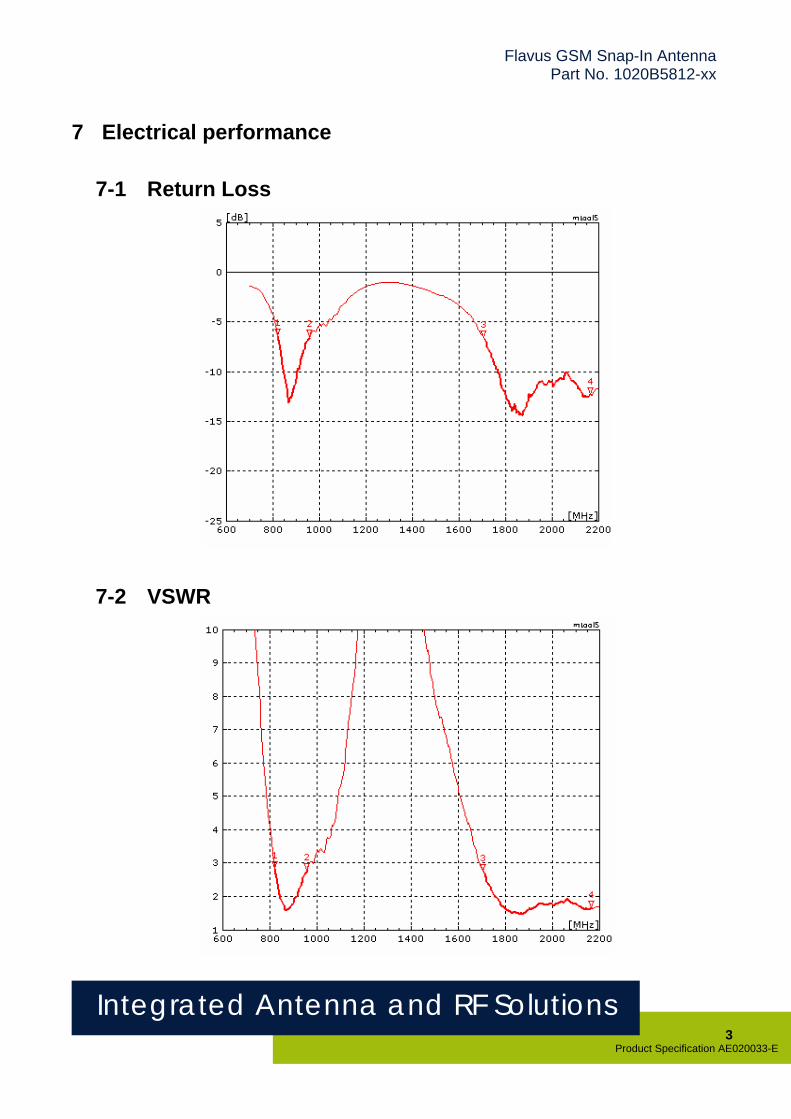
Maximum Return Loss -6dB
Maximum VSWR 3:1
All data measured on Antenova’s reference board, part number 1020B5812-U1
Data given for the 824MHz-960MHz and 1710MHz-
2170MHz frequency ranges
1020B5812-01 1020B5812-02 1020B5812-04
27.3 x 9.6 x 4.05 [mm] 27.3 x 9.6 x 4.25 [mm] 27.3 x 9.6 x 4.85 [mm]
Flavus GSM Snap-In Antenna Part No. 1020B5812-xx
7 Electrical performance
7-1 Return Loss
7-2 VSWR
Integrated Antenna and RF Solutions 3
Product Specification AE020033-E

Flavus GSM Snap-In Antenna Part No. 1020B5812-xx
7-3 Antenna patterns – Low Frequency
Z
X Y
180 deg
180 deg
180 deg
90 deg
90 deg
90 deg
270 deg
270 deg
270 deg
0 deg
0 deg
0 deg
ZY plane XZ plane XY plane
Patterns show combined polarisations measured on reference board 1020B5812-U1. 3D Pattern measured at 892MHz
Integrated Antenna and RF Solutions 4
Product Specification AE020033-E

Flavus GSM Snap-In Antenna Part No. 1020B5812-xx
7-4 Antenna patterns – High Frequency
Z
Integrated Antenna and RF Solutions 5
Product Specification AE020033-E
Patterns show combined polarisations measured on reference board 1020B5812-U1. 3D Pattern measured at 1894MHz
X Y
XY plane ZY plane XZ plane
180 deg
180 deg
180 deg
90 deg
90 deg
90 deg
270 deg
270 deg
270 deg
0 deg
0 deg
0 deg
Flavus GSM Snap-In Antenna Part No. 1020B5812-xx
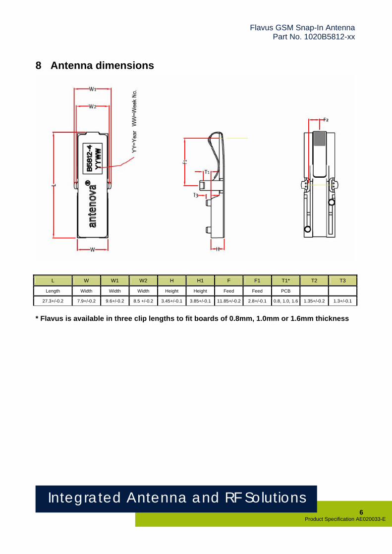
8 Antenna dimensions
L W W1 W2 H H1 F F1 T1* T2 T3
Length Width Width Width Height Height Feed Feed PCB
27.3+/-0.2 7.9+/-0.2 9.6+/-0.2 8.5 +/-0.2 3.45+/-0.1 3.85+/-0.1 11.85+/-0.2 2.8+/-0.1 0.8, 1.0, 1.6 1.35+/-0.2 1.3+/-0.1
* Flavus is available in three clip lengths to fit boards of 0.8mm, 1.0mm or 1.6mm thickness
Integrated Antenna and RF Solutions 6
Product Specification AE020033-E
Flavus GSM Snap-In Antenna Part No. 1020B5812-xx
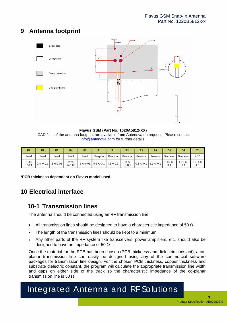
9 Antenna footprint
Flavus GSM (Part No: 1020A5812-XX) CAD files of the antenna footprint are available from Antenova on request. Please contact
[email protected] for further details.
F1 F2 F3 F4 F5 S1 P1 P2 P3 P4 D1 D2 T*
Feed Feed Feed Feed Feed Snap-In Position Position Position Position Diameter Diameter PCB
18.85 +/-0.1 2.8 +/-0.1 2 +/-0.05 2.25
+/-0.05 5 +/-0.05 5.6 +/-0.1 4.5+/-0.1 11.5 +/- 0.1 0.3 +/-0.1 5.9 +/-0.1 3.05 +/-
0.1 1.75 +/-
0.1
0.8, 1.0, 1.6
*PCB thickness dependent on Flavus model used.
10 Electrical interface
10-1 Transmission lines The antenna should be connected using an RF transmission line. • All transmission lines should be designed to have a characteristic impedance of 50 Ω
• The length of the transmission lines should be kept to a minimum
• Any other parts of the RF system like transceivers, power amplifiers, etc, should also be designed to have an impedance of 50 Ω
Once the material for the PCB has been chosen (PCB thickness and dielectric constant), a co-planar transmission line can easily be designed using any of the commercial software packages for transmission line design. For the chosen PCB thickness, copper thickness and substrate dielectric constant, the program will calculate the appropriate transmission line width and gaps on either side of the track so the characteristic impedance of the co-planar transmission line is 50 Ω.
Integrated Antenna and RF Solutions 7
Product Specification AE020033-E

Flavus GSM Snap-In Antenna Part No. 1020B5812-xx
10-2 Matching circuit The antenna requires a matching circuit that must be optimized for each customer’s product. The matching circuit will require up to three components and the following pad layout should be designed into the device so the correct circuit can be installed:
In addition to the matching circuit, a separate DC blocking capacitor will also be required between the radio and the antenna matching circuit.
Dimensions “W” and “T” will depend on the material and thickness of the PCB and must be calculated to give a transmission line with a 50Ω characteristic impedance.
Note: The component values for the matching circuit will vary depending on the size of the PCB and surrounding components. The impedance of the antenna should be measured before selecting suitable matching components. Antenova offers a matching service on request. Contact [email protected] for further information.
Integrated Antenna and RF Solutions 8
Product Specification AE020033-E

Flavus GSM Snap-In Antenna Part No. 1020B5812-xx
10-3 Antenna placement Flavus must be fitted to the device so that power from the antenna can radiate into free space. Antenova recommends fitting the antenna close to the corner of the PCB with few components or metal objects nearby. Ground can be placed at the side of the antenna closest to the feed, but the remaining space around the antenna, including directly above and below should be free from components or conducting objects.
Two recommended configurations are shown below, but other layouts are possible.
Recommended PCB layouts: antenna mounted straight (left) and at 45 degrees (right).
Integrated Antenna and RF Solutions 9
Product Specification AE020033-E

Flavus GSM Snap-In Antenna Part No. 1020B5812-xx
10-4 Reference board The reference board has been designed for evaluation purposes of Flavus GSM and it includes a SMA female connector. The reference board is available with Flavus tuned to cover 5 bands: GSM850/900/1800/1900 and WCDMA , Part number : 1020B5812-04-U1.
Dimensions in mm
To order a reference board contact [email protected]
11 Hazardous material regulation conformance The antenna has been tested to conform to RoHS requirements. A certificate of conformance is available from Antenova’s website.
Integrated Antenna and RF Solutions 10
Product Specification AE020033-E

Flavus GSM Snap-In Antenna Part No. 1020B5812-xx
12 Packaging
12-1 Optimal storage conditions
-10ºC to 40ºC Temperature
Less than 75% RH Humidity
12 Months Shelf Life
Away from corrosive gas and direct sunlight Storage place
12-2 Packaging information The antennas are delivered in trays of 140 pieces packaged in boxes of 980 pieces.
Quantity Number of Trays
Tray Quantity
980 pcs/box 7/Box 140 pcs
Integrated Antenna and RF Solutions 11
Product Specification AE020033-E

Flavus GSM Snap-In Antenna Part No. 1020B5812-xx
12-3 Box label information
Dimensions in mm
Integrated Antenna and RF Solutions 12
Product Specification AE020033-E

Flavus GSM Snap-In Antenna Part No. 1020B5812-xx
www.antenova.com
Corporate Headquarters Antenova Ltd. Far Field House Albert Road Stow-cum-Quy Cambridge CB25 9AR UK Tel: +44 1223810600 Fax: +44 1223 810650 Email: [email protected]
North America Headquarters Antenova Ltd. Rogers Business Park 2541 Technology Drive Suite 403 Elgin, IL 60124 USA Tel: +1 (847) 551 9710 Fax +1 (847) 551 9719 Email: [email protected]
Asia Headquarters Antenova Asia Ltd. 4F, No. 324, Sec. 1, Nei-Hu Road Nei-Hu District Taipei 11493 Taiwan, ROC Tel: +886 (0) 2 8797 8630 Fax: +886 (0) 2 8797 6890 Email: [email protected]
Copyright® 2008 Antenova Ltd. All Rights Reserved. Antenova® and gigaNOVA® are trademarks of Antenova Ltd. Any other names and/or trademarks belong to their respective companies.
The materials provided herein are believed to be reliable and correct at the time of print. Antenova does not warrant the accuracy or completeness of the information, text, graphics or other items contained within these
information. Antenova further assumes no responsibility for the use of this information, and all such information shall be entirely at the user’s risk.
Integrated Antenna and RF Solutions 13
Product Specification AE020033-E