flat top product guide 2007 -...
TRANSCRIPT

Flat Top Product Guide 2007

324
CARBON & STAINLESS STEEL FLAT TOP CHAINSMaterials Used in Chain Production1. Carbon Steel
Plate Material: C45 (mediumcarbon) through hardenedPin Material: C15 (low carbon)carburized and case hardenedProperties: Through hardening topplates to 44-46 Rc provides highstrength, toughness and excellentresistance to wear abrasion.Carburizing chain pins results in highsurface hardness, approximately 60Rc, which provides excellent wearproperties while maintaining aductile core for shock resistance.These chains are particularly wellsuited for glass manufacturing andfor handling heavy-duty automotivecomponents. Note: This material willrust if not properly lubricated.
2. Stainless Steels
2.1Standard (400 Series)
Plate Material: AISI 430 (EN 1.4016)Primary Alloy: 17% ChromiumPin Material: AISI 431 (EN 1.4057)Properties: Rust and corrosionresistant stainless which offers aneconomical price structure.Acceptable for use in applicationswhere high speed or resistance tochemicals are not operatingconsiderations.
2.2Extra Specialty Stainless
Plate Material: EN 1.4589 ExtraPrimary Alloys: 15.5% Chromium,2.5% Nickel, 1.2% Molybdenum,0.5% TitaniumPin Material: Special Cr-Ni Stainlesswhich undergoes an additionalhardening process specificallydesigned to not impair corrosionresistance.Properties: A unique stainless steelfeaturing an additional level of coldrolling which raises both the tensilestrength and surface hardnesssignificantly. This process alsocreates a very flat and smoothsurface which is necessary for highspeed bottling lines. The hardenedpin provides excellent resistance towear and galling even under harshconditions where lubrication may notbe possible.
2.3Austic (300 Series)Plate Material: AISI 304 (EN 1.4301)Primary Alloys: 18.0% Chromium,8.0% NickelPin Material: AISI 301 (EN 1.4310)Properties: The traditionalAustenitic grade of stainless steelwhich provides excellent chemicaland acid resistance. This material isnon-magnetic.
MaterialSpecificationPlate Material
PlateHardness
BrinellHB
Material U.T.S.N/mm2
(P.S.I.)
Corrosion orChemical
Resistance
PlateHardnessRockwell
HRC
COMPARISON CHART
Cost Factor$Application
Medium 1400420-440 44-46 Poor
High Wear
Carbon (200,000) Resistance
AISI 430 750220-250 22-25 Low
Economical
(400 Series) (108,000) Normal duty
Exclusive 1000270-300 27-30 High
High Speed
Cr-Ni-Mo-Ti (145,000) Bottling Lines
AISI 304 850240-270 24-27 Excellent
Acid resistant
(300 Series) (123,000) Non-Magnetic
Note:Extra chains are availablewith vaccuum hardened pins = HB
2
TABLE OF CONTENTSENGINEERED AND PRODUCED WITH LONG LASTING VALUE IN MIND 3
CARBON AND STAINLESS STEEL FLAT TOP CHAINSMaterials Used in Chain Production
Straight Run: Single-Hinge 812/815 4Straight Run: Double-Hinge HD Series 5Straight Run: Rubber Top Series 6Straight Run: 1" Pitch Series 515 7
Side-Flexing: Magnetic system 881M Series 10
Side-Flexing: 881 Series 8Side-Flexing: 8810 Optimal Series 9
PLASTIC FLAT TOP CHAINSMaterials Used in Chain Production 11
Straight Run: Single-Hinge 820/831 12Straight Run: Double-Hinge 821 13Straight Run: Mini-Hinge Series 14Straight Run: LBP Series 821/831 15Side-Flexing: LBP Series 882 16Side-Flexing: 880/879 Series 17Side-Flexing: 882 Series 18
PLASTIC TWO-PIECE SNAP TOP CHAINSStraight Run: 843 Series 20Straight Run: 863 Series 21Side-Flexing: 1843 Series 22Side-Flexing: 1873 Series 23
PLASTIC MULTIPLE — FLEXING CHAINSNovoflex® Series 1700/1701 TAB/1702 241702 Series Plate Tops and Pushers 25
PLASTIC CONVEYOR CHAINSSide-Flexing: CC 600/CC 1400 Series 26
PERMISSIBLE CHAIN WORKING LOADS 37
SPLIT PLASTIC SPROCKETS 28
SPLIT PLASTIC IDLERS 29
DESIGN INFORMATION 39
ENVIRONMENTAL ISSUES AND FRICTIONAL VALUES 38
CORROSION RESISTANCE TABLE 36
Side-Flexing: Magnetic System879/880/8857M 19
Malleable Iron and Sprockets CC600/1400 27
STANDARD SPROCKETS IN STEEL-
COMPACT CURVE AND STRAIGHT-GUIDING SECTIONS 32-33
SPROCKETS FOR TOP CHAINS/GUIDING RINGS 34
CAST IRON/PLASTC 30-31
WEAR STRIPS 35
© Copyright 2005
www.flattopsystems.com

546
S 800 K750 7 1/2 190.5 Not Applicable 3.9 5.8
SS 802 K750 7 1/2 190.5 24 0.6 3.9 5.8
SSE 805 K750 7 1/2 190.5 12 0.3 3.9 5.8
CARBON & STAINLESS STEEL FLAT TOP CHAINSStraight Run: Double-Hinge
800 - 802 - 805(HD Series)
802/805 (HD) SeriesAvailable Materials:• Carbon Steel• 400 Series Stainless Steel• Specialty Stainless Steels
These chains, built inaccordance with ISO 4348(B29.17), are double-hingestraight running conveyor chains.
HD series feature a hinge areatwice that of the 812/815 series.This allows much higher loads to be conveyed in suchapplications as palletizers orheavy crate conveying.
Note: These chains are onlyavailable with a plate width of 7 1/2".
Chain Reference Plate Material
WidthK
mminch mminch
SurfaceFinishMicro
Ib/Ft Kg/m
Weight
Symbol Description Inch Metric
P Chain Pitch 1 1/2 38.1L Height Over CL 1/4 6.4
TT Plate Thickness 1/8 3.1Q Hinge Width 3 11/64 80.5
GC Guide Clearance 1 3/4 82.5H Plate Btm. to Chain Btm. 3/8 9.5E P in Diameter 1/4 6.4
p
E
L
L
r
K
Q
GC
TT
Travel
Sprockets page 28-31DO
800 - 802 - 805(HD Series)
5
CARBON & STAINLESS STEEL FLAT TOP CHAINSStraight Run: Single-Hinge
S 815 K 325 3 1/4 82.5 1.75 2.60S 815 K 400 4 101.6 2.02 3.00S 815 K 450 4 1/2 114.3 Not Not 2.22 3.30S 815 K 600 6 152.4 Applicable Applicable 2.82 4.20S 815 K 750 7 1/2 190.5 3.43 5.10
SS 812 K 325 3 1/4 82.5 24 0.6 1.75 2.60SS 812 K 750 7 1/2 190.5 3.43 5.10
SSE 815 K 325 3 1/4 82.5 1.75 2.60SSE 815 K 350 3 1/2 89.9 1.80 2.70SSE 815 K 400 4 101.6 2.02 3.00SSE 815 K 450 4 1/2 114.3 24 0.6 2.22 3.30SSE 815 K 600 6 152.4 2.82 4.20SSE 815 K 750 7 1/2 190.5 3.43 5.10
SSA 815 K 325 3 1/4 82.5 1.75 2.50SSA 815 K 450 4 1/2 114.3 16 0.4 2.20 3.30SSA 815 K 750 7 1/2 190.5 3.40 5.10
SSS 815 K 325 3 1/4 82.5 8 0.2 1.75 SSS 815 K 350 3 1/2 88.9 1.81 2.70
Chain Reference Plate Material
WidthK
mminch mm inch
Surface Finishin Micro
Kg/mIb/Ft
Weight
812-815812/815 SeriesAvailable Materials:• Carbon Steel• 400 Series Stainless Steel• Specialty Stainless Steels• 300 Series Stainless Steel
These chains are built inaccordance with ISO 4348(B29.17) and are single-hingestraight running conveyorchains, all featuring the samehinge area dimensions. Thechains do differ in terms of platewidth (maximum 7 1/2") andmaterial grades. A wide selectionof stainless steel conveyor chainsis available thus providingthe solution to your requirements,whether they be speed, load, chemical resistance or purelybudgetary.
The grades of materials areclearly defined by symbolswhich simplifies the selection.
The symbol signifies a topplate handling process calledSUPERFINISH. This is a finegrinding and polishing operationwhich ensures the smoothestand flattest stainless steel chainavailable. This finish is ideal forcombination bottling lines whichmay handle both glass and PETbottles or where sensitiveinspection devices are beingused.
p
E
H
L
r
K
Q
GC
TT
Travel
Symbol Description Inch Metric
P Chain Pitch 1 1/2 38.1L Height Over CL 1/4 6.4
TT Plate Thickness 1/8 3.1Q Hinge Width 1 11/16 42.1
GC Guide Clearance 1 3/4 44.5H P late Btm. to Chain Btm. 3/8 9.8E Pin Diameter 1/4 6.4r Min. Backflex Radius 6 150.0
Sprockets page 28-31DO
2.60
812-815

76 8
STAINLESS STEEL FLAT TOP CHAINSStraight Run: 1" Pitch
515515 SeriesAvailable Materials:• Specialty Stainless Steels
These chains are built inaccordance with ISO 4348(B29.17) and are single-hingestraight running conveyor chainsbut feature a smaller pitch thanthe popular 815 series. The pitchof 1" allows compact conveyordesigns, especially suitable forthe transportation of productswith narrow dimensions. Thehinge width is identical to the 815series but much smaller platewidths are available.
515 series are particularly usedon the in-feed of bottle washingequipment due to excellent endtransferability.
Chain Reference PlateMaterial
WidthK
inch mm mminch
Surface Finishin Micro
Ib/Ft Kg/m
Weight
Symbol Description Inch Metric
P Chain Pitch 1 25.4L Height Over CL 1/4 6.4
TT Plate Thickness 1/8 3.1Q Hinge Width 1 21/32 42.1
GC Guide Clearance 1 3/4 44.5H Plate Btm. to Chain Btm. 3/8 9.8E Pin Diameter 1/4 6.4r Min. Backflex Radius 4 100.0
216-515-13 13 13 4.18 106.14 4.25 108 0.75 20 1.75 45 4.42 2.00216-515-15 1 Piece 15 15 4.80 122.17 4.88 124 0.75 20 1.90 48 6.41 2.90216-515-17 Solid 17 17 5.44 138.23 5.55 141 0.75 20 2.00 53 7.74 3.50216-515-19 Poly- 19 19 6.08 154.32 6.18 157 0.75 20 2.75 70 9.94 4.50216-515-21 amid 21 21 6.71 170.42 6.81 173 0.75 20 3.15 80 13.26 6.00216-515-23 23 23 7.34 186.54 7.48 190 0.75 20 3.35 85 17.24 7.80216-515-25 25 25 7.98 202.66 8.11 206 0.75 20 3.50 90 21.00 9.50
Reference
Number ofTeeth
Pitch CircleDia. PD
Stock BoredB
Ib/ea Kg/eaInch MetricInch MetricInch MetricInch MetricActual Effect.
WeightOutside Dia.
ODMax. Bore
dB
p
E
H
L
r
W
Q
GC
TT
Travel
d BD PD
O
W
SSE 515 K 217 2 5/32 55.0 1.54 2.3
SSE 515 K 236 2 23/64 60.0 1.61 2.4
SSE 515 K 250 2 1/2 63.5 1.68 2.5
SSE 515 K 283 2 53/64 72.0 24 0.6 1.81 2.7
SSE 515 K 325 3 1/4 82.5 1.95 2.9
SSE 515 K 350 3 1/2 88.9 2.00 3.0
SSE 515 K 400 4 101.6 2.20 3.3
1.65"42.5 Sprocket
Type &Material
515
7
STAINLESS STEEL FLAT TOP CHAINSStraight Run: Vulcanized Rubber Pad815/805 Griptop SeriesAvailable Materials:• Specialty Stainless Steels
with vulcanized Rubber Top Pad
• Carbon Steel plate material (to order)
These chains were designed toprovide a top plate surface witha grip effect to allow products tobe inclined on conveyors at anangle of up to 20°.
The basic chains utilized are the815 and 805 series in straightrunning format. These chainsare intended to replace roughtop belting for crate or boxhandling and provide thefollowing advantages overtraditional belting:
• No slippage due to positivetooth sprocket drives, one wayclutches are not needed.
• Higher loading capacities.• Planned maintenance
improved as chain wear iseasier to monitor than thetendency of a belt to tear.
Straight running 815 TABversion also provides a methodof chain return which preventsthe rubber top from having torun against another surface.
For general chain dimensionsrefer to relevant catalog pages
Chain Type Page No.
815 5815 TAB (see 881 TAB) 10805 6
SSER 815 K 325 VR 3 1/4 82.50 3 76.00 1/8 3.00 3 75.00 1.90 2.80
SSE 815 K 750 VR NBR 7 1/2 190.50 5 5/16 135.00 1/8 3.00 6 150.00 3.70 5.50
SSE 805 K 750 VR Rubber 7 1/2 190.50 5 5/16 135.00 1/8 3.00 6 150.00 4.20 6.20
SSER 815 K 325 TAB VR 82.50 3 76.00 1/8 3.00 3 75.00 2.30 3.40
Chain ReferenceRubber Material
Plate WidthK
Rubber ThickT
Ib/Ft Kg/m
Weight
inch mminch mm
Rubber WidthX
inch mminch mm
Back BendRadius r
Travel
W
WX
815 TAB
815
815 TAB
805
T
T
K
K
r
Sprockets page 28-31DO
Travel
Griptop®
815 VR - 805 VR815 TAB VR
3 1/4
Griptop815 VR - 805 VR815 TAB VR
®
9811
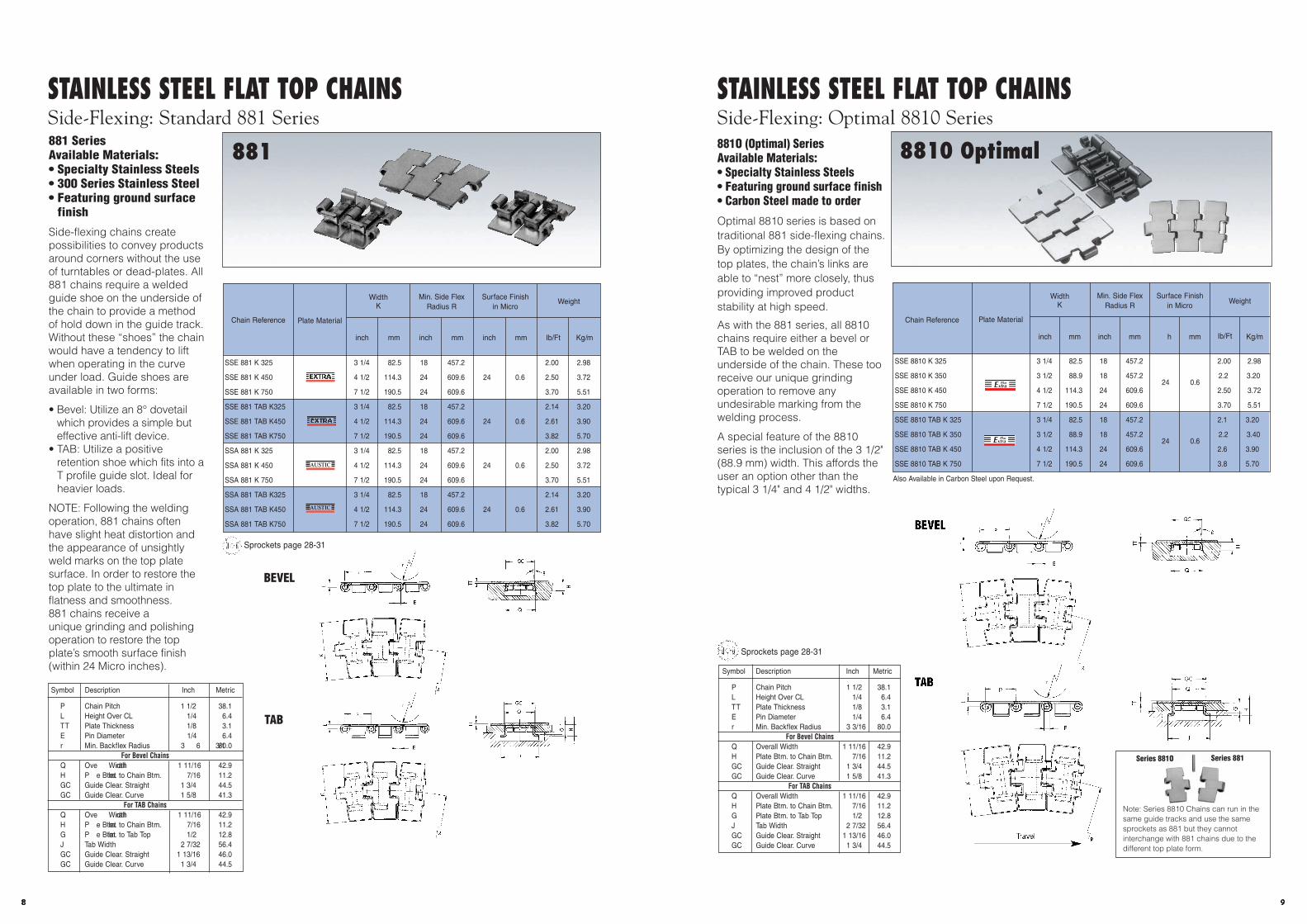
Note: Series 8810 Chains can run in thesame guide tracks and use the samesprockets as 881 but they cannotinterchange with 881 chains due to thedifferent top plate form.
STAINLESS STEEL FLAT TOP CHAINSSide-Flexing: Optimal 8810 Series881O (Optimal) SeriesAvailable Materials:• Specialty Stainless Steels• Featuring ground surface finish• Carbon Steel made to order
Optimal 8810 series is based on traditional 881 side-flexing chains.By optimizing the design of thetop plates, the chain’s links areable to “nest” more closely, thusproviding improved productstability at high speed.
As with the 881 series, all 8810chains require either a bevel orTAB to be welded on theunderside of the chain. These tooreceive our unique grindingoperation to remove anyundesirable marking from thewelding process.
A special feature of the 8810series is the inclusion of the 3 1/2"(88.9 mm) width. This affords theuser an option other than thetypical 3 1/4" and 4 1/2" widths.
Symbol Description Inch Metric
P Chain Pitch 1 1/2 38.1L Height Over CL 1/4 6.4TT Plate Thickness 1/8 3.1E Pin Diameter 1/4 6.4r Min. Backflex Radius 3 3/16 80.0
For Bevel ChainsQ Overall Width 1 11/16 42.9H Plate Btm. to Chain Btm. 7/16 11.2GC Guide Clear. Straight 1 3/4 44.5GC Guide Clear. Curve 1 5/8 41.3
For TAB ChainsQ Overall Width 1 11/16 42.9H Plate Btm. to Chain Btm. 7/16 11.2G Plate Btm. to Tab Top 1/2 12.8J Tab Width 2 7/32 56.4GC Guide Clear. Straight 1 13/16 46.0GC Guide Clear. Curve 1 3/4 44.5
SSE 8810 K 325 3 1/4 82.5 18 457.2 2.00 2.98
SSE 8810 K 350 3 1/2 88.9 18 457.224 0.6
2.2 3.20
SSE 8810 K 450 4 1/2 114.3 24 609.6 2.50 3.72
SSE 8810 K 750 7 1/2 190.5 24 609.6 3.70 5.51
SSE 8810 TAB K 325 3 1/4 82.5 18 457.2 2.1 3.20
SSE 8810 TAB K 350 3 1/2 88.9 18 457.224 0.6
2.2 3.40
SSE 8810 TAB K 450 4 1/2 114.3 24 609.6 2.6 3.90
SSE 8810 TAB K 750 7 1/2 190.5 24 609.6 3.8 5.70
Also Available in Carbon Steel upon Request.
Chain Reference Plate Material
WidthK
mminch mm inch
Surface Finishin Micro
mminch
Min. Side FlexRadius R
Kg/mIb/Ft
Weight
R
p
E
L
r
Q
TT
8
GC
H
K
R
p
E
L
r
J
TT
Q
GC
G H
K
R
rGC
Travel
BEVEL
TAB
8810 Optimal
Sprockets page 28-31
Series 881Series 881O
8810 Optimal
10
STAINLESS STEEL FLAT TOP CHAINSSide-Flexing: Standard 881 Series
881881 SeriesAvailable Materials:• Specialty Stainless Steels• 300 Series Stainless Steel• Featuring ground surface
finish
Side-flexing chains createpossibilities to convey productsaround corners without the useof turntables or dead-plates. All881 chains require a weldedguide shoe on the underside ofthe chain to provide a methodof hold down in the guide track.Without these “shoes” the chainwould have a tendency to liftwhen operating in the curveunder load. Guide shoes areavailable in two forms:
• Bevel: Utilize an 8° dovetailwhich provides a simple buteffective anti-lift device.
• TAB: Utilize a positiveretention shoe which fits into aT profile guide slot. Ideal forheavier loads.
NOTE: Following the weldingoperation, 881 chains oftenhave slight heat distortion andthe appearance of unsightlyweld marks on the top platesurface. In order to restore thetop plate to the ultimate inflatness and smoothness.881 chains receive aunique grinding and polishingoperation to restore the topplate’s smooth surface finish(within 24 Micro inches).
Chain Reference Plate Material
WidthK
mminch mminch
Surface Finishin Micro
mminch
Min. Side FlexRadius R
Kg/mIb/Ft
Weight
p
E
L
r
J
TT
Q
GC
G H
K
R
p
E
L
r
Q
TT
8
GCH
K
RSymbol Description Inch Metric
P Chain Pitch 1 1/2 38.1L Height Over CL 1/4 6.4TT Plate Thickness 1/8 3.1E Pin Diameter 1/4 6.4r Min. Backflex Radius 3 3/16 80.0
For Bevel ChainsQ Ove rall Width 1 11/16 42.9H P late Btm. to Chain Btm. 7/16 11.2GC Guide Clear. Straight 1 3/4 44.5GC Guide Clear. Curve 1 5/8 41.3
For TAB ChainsQ Ove rall Width 1 11/16 42.9H P late Btm. to Chain Btm. 7/16 11.2G P late Btm. to Tab Top 1/2 12.8J Tab Width 2 7/32 56.4GC Guide Clear. Straight 1 13/16 46.0GC Guide Clear. Curve 1 3/4 44.5
SSE 881 K 325 3 1/4 82.5 18 457.2 2.00 2.98
SSE 881 K 450 4 1/2 114.3 24 609.6 24 0.6 2.50 3.72
SSE 881 K 750 7 1/2 190.5 24 609.6 3.70 5.51
SSE 881 TAB K325 3 1/4 82.5 18 457.2 2.14 3.20
SSE 881 TAB K450 4 1/2 114.3 24 609.6 24 0.6 2.61 3.90
SSE 881 TAB K750 7 1/2 190.5 24 609.6 3.82 5.70
SSA 881 K 325 3 1/4 82.5 18 457.2 2.00 2.98
SSA 881 K 450 4 1/2 114.3 24 609.6 24 0.6 2.50 3.72
SSA 881 K 750 7 1/2 190.5 24 609.6 3.70 5.51
SSA 881 TAB K325 3 1/4 82.5 18 457.2 2.14 3.20
SSA 881 TAB K450 4 1/2 114.3 24 609.6 24 0.6 2.61 3.90
SSA 881 TAB K750 7 1/2 190.5 24 609.6 3.82 5.70
Sprockets page 28-31DO
TAB
BEVEL
881
1014
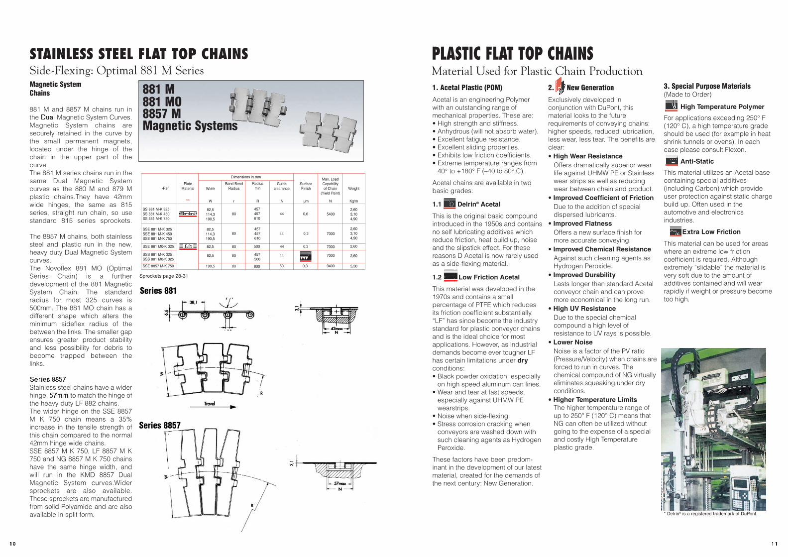
PLASTIC FLAT TOP CHAINSMaterial Used for Plastic Chain Production1. Acetal Plastic (POM)
Acetal is an engineering Polymerwith an outstanding range ofmechanical properties. These are:• High strength and stiffness. • Anhydrous (will not absorb water).• Excellent fatigue resistance. • Excellent sliding properties. • Exhibits low friction coefficients.• Extreme temperature ranges from
40° to +180° F (–40 to 80° C).
Acetal chains are available in twobasic grades:
1.1 Delrin® Acetal
This is the original basic compoundintroduced in the 1950s and containsno self lubricating additives whichreduce friction, heat build up, noiseand the slipstick effect. For thesereasons D Acetal is now rarely usedas a side-flexing material.
1.2 Low Friction Acetal
This material was developed in the1970s and contains a smallpercentage of PTFE which reducesits friction coefficient substantially.“LF” has since become the industrystandard for plastic conveyor chainsand is the ideal choice for mostapplications. However, as industrialdemands become ever tougher LFhas certain limitations under dryconditions:• Black powder oxidation, especially
on high speed aluminum can lines.• Wear and tear at fast speeds,
especially against UHMW PEwearstrips.
• Noise when side-flexing. • Stress corrosion cracking when
conveyors are washed down withsuch cleaning agents as HydrogenPeroxide.
These factors have been predom-inant in the development of our latestmaterial, created for the demands ofthe next century: New Generation.
2. New Generation
Exclusively developed inconjunction with DuPont, thismaterial looks to the futurerequirements of conveying chains:higher speeds, reduced lubrication,less wear, less tear. The benefits areclear:• High Wear Resistance
Offers dramatically superior wearlife against UHMW PE or Stainlesswear strips as well as reducingwear between chain and product.
• Improved Coefficient of FrictionDue to the addition of specialdispersed lubricants.
• Improved FlatnessOffers a new surface finish formore accurate conveying.
• Improved Chemical ResistanceAgainst such cleaning agents asHydrogen Peroxide.
• Improved DurabilityLasts longer than standard Acetalconveyor chain and can provemore economical in the long run.
• High UV ResistanceDue to the special chemicalcompound a high level ofresistance to UV rays is possible.
• Lower NoiseNoise is a factor of the PV ratio(Pressure/Velocity) when chains areforced to run in curves. Thechemical compound of NG virtuallyeliminates squeaking under dryconditions.
• Higher Temperature LimitsThe higher temperature range ofup to 250° F (120° C) means thatNG can often be utilized withoutgoing to the expense of a specialand costly High Temperatureplastic grade.
3. Special Purpose Materials(Made to Order)
High Temperature Polymer
For applications exceeding 250° F(120° C), a high temperature gradeshould be used (for example in heatshrink tunnels or ovens). In eachcase please consult Flexon.
Anti-Static
This material utilizes an Acetal basecontaining special additives(including Carbon) which provideuser protection against static chargebuild up. Often used in theautomotive and electronicsindustries.
Extra Low Friction
This material can be used for areaswhere an extreme low frictioncoefficient is required. Althoughextremely “slidable” the material isvery soft due to the amount ofadditives contained and will wearrapidly if weight or pressure becometoo high.
* Delrin® is a registered trademark of DuPont.
11
Magnetic SystemChains
881 M and 8857 M chains run inthe Dual Magnetic System Curves.Magnetic System chains aresecurely retained in the curve bythe small permanent magnets,located under the hinge of thechain in the upper part of thecurve.The 881 M series chains run in thesame Dual Magnetic Systemcurves as the 880 M and 879 Mplastic chains.They have 42mmwide hinges, the same as 815series, straight run chain, so usestandard 815 series sprockets.
The 8857 M chains, both stainlesssteel and plastic run in the new,heavy duty Dual Magnetic Systemcurves.The Novoflex 881 MO (OptimalSeries Chain) is a furtherdevelopment of the 881 MagneticSystem Chain. The standardradius for most 325 curves is500mm. The 881 MO chain has adifferent shape which alters theminimum sideflex radius of thebetween the links. The smaller gapensures greater product stabilityand less possibility for debris tobecome trapped between thelinks.
Series 8857Stainless steel chains have a widerhinge, 57mm to match the hinge ofthe heavy duty LF 882 chains.The wider hinge on the SSE 8857M K 750 chain means a 35%increase in the tensile strength ofthis chain compared to the normal42mm hinge wide chains.SSE 8857 M K 750, LF 8857 M K750 and NG 8857 M K 750 chainshave the same hinge width, andwill run in the KMD 8857 DualMagnetic System curves.Widersprockets are also available.These sprockets are manufacturedfrom solid Polyamide and are alsoavailable in split form.
881 M881 MO8857 MMagnetic Systems
Series 881
Series 8857
Flexon -Ref
SS 881 M-K 325SS 881 M-K 450SS 881 M-K 750
SSE 881 M0-K 325
SSE 8857 M-K 750
SSS 881 M-K 325SSS 881 M0-K 325
PlateMaterial Width
82,5114,3190,5
80457457610
44 0,6 54002,603,104,90
Band BendRadius
Radiusmin
82,5
82,5
SSE 881 M-K 325SSE 881 M-K 450SSE 881 M-K 750
** W r R N um N Kg/m
Guideclearance
SurfaceFinish
Max. LoadCapabilityof Chain
(Yield Point)Weight
82,5114,3190,5
80457457610
44 0,3 70002,603,104,90
80 500 44 0,3 7000 2,60
80 457500
44 7000 2,60
190,5 80 800 60 0,3 9400 5,30
Dimensions in mm
STAINLESS STEEL FLAT TOP CHAINSSide-Flexing: Optimal 881 M Series
Sprockets page 28-31

16
PLASTIC FLAT TOP CHAINSStraight Running: Double-Hinge Series 821
821821 SeriesAvailable Materials:• Delrin Acetal (to order)• Low Friction Acetal• New Generation• Anti-Static Acetal (to
order)• Stainless Steel Pins
These are heavy dutystraight running chainswhich, due to the length ofthe pin and hinge area, haveload carrying capacities onthe same level as the single-hinge stainless steel 815series. As with the 820chains the 821 hasunderside reinforcement butthe design of the webmeans that the sprockets donot require grooving.Sprockets for these chainsare thus identical to the 805Double-Hinge Series.
All 821 chains feature thespecial overlapping topplate system of “arcuic”design which has the dualbenefit of eliminating thegaps between plates andcreating a self clearingaction to remove debrisor dust.
821 chains feature thethicker top plate of 3/16"which makes themcompatible in ride height tothe 831, 879 and 882 series.
Symbol Description Inch Metric
P Chain Pitch 1 1/2 38.1L Height Over CL 5/16 7.9Q Hinge Width 5 3/8 136.5GC Guide Clearance 5 1/2 139.7E Pin Diameter 1/4 6.4r Min. Backflex Radius 3 3/16 80.0
LF 821 K 750 7 1/2 190.5 1.70 2.53
LF 821 K 1000 10 254.0 3/16 4.8 3/8 9.5 2.00 2.98
LF 821 K 1200 12 304.8 2.20 3.27
NG 821 K 750 7 1/2 190.5 1.70 2.53
NG 821 K 1000 10 254.0 3/16 4.8 3/8 9.5 2.00 2.98
NG 821 K 1200 12 304.8 2.20 3.27
ChainReference
Plate Material
Flight ThicknessTT
WidthK
DimensionH
inch mminch mminch mm Ib/Ft Kg/m
Weight
Ep
r
GCQ
TT
K
H
L
Sprockets page 28-31DO
Travel
1315
PLASTIC FLAT TOP CHAINSStraight Running: Single-Hinge 820 and 831 Series
820 - 831
820/831 SeriesAvailable Materials:• Delrin Acetal• Low Friction Acetal• New Generation• Anti-Static Acetal• Stainless Steel Pins
These chains were designedas the plastic alternative to thestainless steel 815 series andconsequently share the samebasic dimensions. However,plastic chains are not able towithstand the loads carried bysteel chains and therefore acentral reinforcing bar isfeatured on the underside. Forthis reason the sprockets for820 and 831 chains aregrooved to allow for this bar.
All 820 and 831 chains featurea special overlapping top platesystem of “arcuic” designwhich has the dual benefit ofeliminating the gaps betweenplates and creating a selfclearing action to removedebris or dust.
831 chains have the samehinge and overall dimensionsas the 820 series but feature athicker top plate of 3/16" whichmakes them compatible in rideheight to the 821, 879 and 882series.
ChainReference Plate Material
Flight ThicknessTT
WidthK
DimensionH
inch mminch mminch mm Ib/Ft Kg/m
Weight
Symbol Description Inch Metric
P Chain Pitch 1 1/2 38.1L Height Over CL 9/32 7.1Q Hinge Width 1 21/32 42.1GC Guide Clearance 1 3/4 44.5E Pin Diameter 1/4 6.4r Min. Backflex Radius 3 3/16 80.0
L
Ep
r
GCQ
TT
K
H
Novonorm®
D 820 K 325 3 1/4 82.5 0.56 0.83
D 820 K 400 4 101.6 0.64 0.95
D 820 K 450 4 1/2 114.3 5/32 4.0 3/8 9.5 0.69 1.03
D 820 K 600 6 152.4 0.84 1.25
D 820 K 750 7 1/2 190.5 0.99 1.47
LF 820 K 325 3 1/4 82.5 0.56 0.83
LF 820 K 350 3 1/2 88.9 0.60 0.89
LF 820 K 400 4 101.6 5/32 4.0 3/8 9.5 0.64 0.95
LF 820 K 450 4 1/2 114.3 0.69 1.03
LF 820 K 600 6 152.4 0.84 1.25
LF 820 K 750 7 1/2 190.5 0.99 1.47
LF 831 K 325 3 1/4 82.5 0.56 0.83
LF 831 K 450 4 1/2 114.3 3/16 4.8 11/32 8.7 0.69 1.03
LF 831 K 750 7 1/2 190.5 0.99 1.47
NG 820 K 325 3 1/4 82.5 0.56 0.83
NG 820 K 350 3 1/2 88.9 0.60 0.89
NG 820 K 400 4 101.6 5/32 4.0 3/8 9.5 0.64 0.95
NG 820 K 450 4 1/2 114.3 0.69 1.03
NG 820 K 600 6 152.4 0.84 1.25
NG 820 K 750 7 1/2 190.5 0.99 1.47
NG 831 K 325 3 1/4 82.5 0.56 0.83
NG 831 K 450 4 1/2 114.3 3/16 4.8 11/32 8.7 0.69 1.03
NG 831 K 750 7 1/2 190.5 0.99 1.47
AS 820 K 325 3 1/4 82.5 5/32 4.0 3/8 9.5 0.56 0.83
AS 831 K 325 3 1/4 82.5 3/16 4.8 11/32 8.7 0.56 0.83
Sprockets page 28-31DO
Travel
12
820 - 831 821

18
h
r
p
E
D
K
Q
GC
C
SPECIALTY PLASTIC FLAT TOP CHAINSStraight Running: LBP 821/831 Low Back Pressure
LBP 821LBP 831
LBP SeriesAvailable Materials:• Low Friction Acetal• New Generation Rollers• Stainless Steel Pins
LBP (Low Back Pressure) chainsare used in conveyor systemswhere backline pressure canoccur. Under these conditionsthe chain will continue to rununderneath the product but thetop surface rollers will rotate,remove line pressure andconsequently prevent damage toproducts. The LBP chain willprovide positive motion whenbackline pressure is removed.
The rollers are attached to thetop of the chain by a series ofstainless steel axles. The smallcenter distance of these axlesoffers a very stable conveyingsurface which can also be usedfor heavy duty goods. Rollersproduced in New Generationmaterial provide reducedoperating noise levels.
821 LBP series are available inall standard widths.
Symbol Description Inch Metric
For LBP 821 series
P Chain Pitch 1.50 38.1B Plate Btm. to Top of Chain 0.75 19.3L Height Over CL 0.89 22.5C Overall Chain Height 1.14 29.0Q Overall Width 5.37 136.5GC Guide Clearance 5.50 139.7E Pin Diameter 0.25 6.4r Min. Backflex Radius 16.00 406.4
Symbol Description Inch Metric
For LBP 831 series
P Chain Pitch 1.50 38.1B Plate Btm. to Top of Chain 0.75 19.3L Height Over CL 0.89 21.7C Overall Chain Height 1.14 29.0Q Overall Width 5.37 42.1GC Guide Clearance 5.50 44.5E Pin Diameter 0.25 6.4r Min. Backflex Radius 16.00 406.4
LBP 821 K 750 7 1/2 190.5 0.44 11.0 3/8 9.50 2.22 5.52LBP 821 K 1000 10 254.0 0.44 11.0 3/8 9.50 2.68 6.90LBP 821 K 1200 12 309.8 0.44 11.0 3/8 9.50 3.21 8.01
LBP 831 K 325 3 1/4 82.50 0.44 11.0 11/32 8.70 3.21 2.15LBP 831 K 450 4 1/2 114.30 0.44 11.0 11/32 8.70 3.21 2.85
ChainReference
PlateMaterial
Roller DiameterD
WidthK
DimensionH
inch mminch mminch mm Ib/Ft Kg/m
WeightRoller
Material
Sprockets page 28-31DO
Travel
L
B
Q
GC
C
C
Bh
D
E
p
L
821
831
r
r
1517
PLASTIC FLAT TOP CHAINSStraight Run: Mini SeriesMini SeriesAvailable Materials:• Delrin Acetal (Black)• Delrin Acetal (Gray)• Low Friction Acetal• Stainless Steel Pins
Exclusive Mini-hinge designs foruse in areas where space isrestricted or for thetransportation of smallcontainers or bottles.
Ideal for the pharmaceuticalindustry and for the filling ofminiature spirit bottles.
Both Series 38 K 32 and K 50chains have their own uniquehinge designs which create newpossibilities for conveyordesigners.
Sprockets standard 820 seriesbut with narrow width.
Symbol Description Inch Metric
P Chain Pitch 1 1/2 38.1L Height Over CL (K32) 1/4 6.4L Height Over CL (K50) 15/64 6.0Q Hinge Width (K32) 1 1/4 32.0Q Hinge Width (K50) 13/16 20.0H Plate Btm. to Chain Btm. 3/8 9.2E Pin Diameter 1/4 6.0r Min. Backflex Radius 3 3/16 80.0
D 38 K32 1 1/4 32.0 9/64 3.5 0.362 9.2 0.20 0.30
D 38 K50 2 50.0 1/8 3.0 0.354 9.0 0.23 0.35
LF 38 K50 2 50.0 1/8 3.0 0.354 9.0 0.23 0.35
ChainReference Plate Material
Flight ThicknessTT
WidthK
DimensionH
inch mminch mminch mm Ib/Ft Kg/m
Weight
Black
L
T T
pE
K
Q
H
pE
L
TT
K
H
38 K32
38 K50
Sprockets page 28-31DO
Travel
Mini Series
r
14
Mini Series LBP 821LBP 831
20
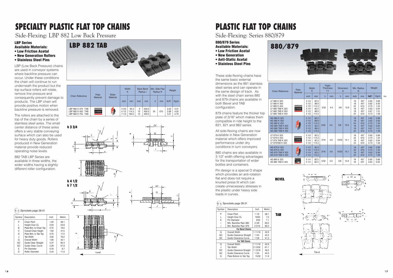
PLASTIC FLAT TOP CHAINSSide-Flexing: Series 880/879
880/879880/879 SeriesAvailable Materials:• Low Friction Acetal• New Generation• Anti-Static Acetal• Stainless Steel Pins
These side-flexing chains havethe same basic externaldimensions as the 881 stainlesssteel series and can operate inthe same design of track. Aswith the steel chain series 880and 879 chains are available inboth Bevel and TABconfiguration.
879 chains feature the thicker topplate of 3/16" which makes themcompatible in ride height to the831, 821 and 882 series.
All side-flexing chains are nowavailable in New Generationmaterial which offers improvedperformance under dryconditions in turn conveyers.
880 chains are also available in 3 1/2" width offering advantagesfor the transportation of widerbottles and containers.
Pin design is a special D shapewhich provides an anti-rotationflat and does not require aknurled press fit which cancreate unnecessary stresses inthe plastic under heavy sideloads in curves.
Chain ReferencePlate
Material
WidthK
mminch mm inch mm inch mm inch
Min. RadiusR
DimensionH
FlightThickness
TT
Kg/mIb/Ft
Weight
Symbol Description Inch Metric
P Chain Pitch 1 1/2 38.1L Height Over CL 19/64 7.5E Pin Diameter 9/32 7.1r Min. Backflex Rad. 880 2 3/8 60.0r Min. Backflex Rad. 879 3 3/16 80.0
For Bevel ChainsQ Overall Width 1 11/16 42.9
GC Guide Clearance Straight 1 3/4 44.5GC Guide Clearance Curve 1 5/8 41.3
For TAB ChainsQ Overall Width 1 11/16 42.9J Tab Width 2 13/32 61.1
GC Guide Clearance Straight 1 13/16 46.0GC Guide Clearance Curve 1 3/4 44.5G Plate Bottom to Tab Top 15/32 11.9
pL E
GC
H
Q8°
TT
pL
E
Q
H
J
K
TT
G
R
R
K
TAB
BEVEL
LF 880 K 325 3 1/4 82.5 18 457 0.60 0.89LF 880 K 350 3 1/2 88.9 18 457 0.62 0.92LF 880 K 450 4 1/2 114.3 24 610 0.70 1.04LF 880 TAB K 325 3 1/4 82.5 18 457 0.63 0.94LF 880 TAB K 350 3 1/2 88.9 18 457 0.67 1.01LF 880 TAB K 450 4 1/2 114.3 24 610 0.73 1.09
NG 880 K 325 3 1/4 82.5 18 457 0.60 0.89NG 880 K 350 3 1/2 88.9 18 457 0.62 0.92NG 880 K 450 4 1/2 114.3 24 610 0.70 1.04NG 880 TAB K 325 3 1/4 82.5 18 457 0.63 0.94NG 880 TAB K 350 3 1/2 88.9 18 457 0.67 1.01NG 880 TAB K 450 4 1/2 114.3 24 610 0.73 1.09
LF 879 K 325 3 1/4 82.5 18 457 0.60 0.89LF 879 K 450 4 1/2 114.3 24 610 0.70 1.04LF 879 TAB K 325 3 1/4 82.5 18 457 0.63 0.94LF 879TAB K 450 4 1/2 114.3 24 610 0.73 1.09
NG 879 K 325 3 1/4 82.5 18 457 0.60 0.89NG 879 K 450 4 1/2 114.3 24 610 0.70 1.04NG 879 TAB K 325 3 1/4 82.5 18 457 0.63 0.94NG 879 TAB K 450 4 1/2 114.3 24 610 0.73 1.09
AS 880 K 325 3 1/4 82.5 18 457 0.60 0.89AS 880 TAB K 325 3 1/4 82.5 18 457 0.63 0.945/32 4.0 5/8 15.9
5/32 4.0 5/8 15.9
5/32 4.0 5/8 15.9
3/16 4.8 19/32 15.1
3/16 4.8 19/32 15.1
Sprockets page 28-31DO
Travel
1719
SPECIALTY PLASTIC FLAT TOP CHAINSSide-Flexing: LBP 882 Low Back Pressure
LBP 882LBP SeriesAvailable Materials:• Low Friction Acetal• New Generation Rollers• Stainless Steel Pins
LBP (Low Back Pressure) chainsare used in conveyor systemswhere backline pressure canoccur. Under these conditionsthe chain will continue to rununderneath the product but thetop surface rollers will rotate,remove line pressure andconsequently prevent damage toproducts. The LBP chain willprovide positive motion whenbackline pressure is removed.
The rollers are attached to thetop of the chain by a series ofstainless steel axles. The smallcenter distance of these axlesoffers a very stable conveyingsurface which can also be usedfor heavy duty goods. Rollersproduced in New Generationmaterial provide reducedoperating noise levels.
882 TAB LBP Series areavailable in three widths, thewider widths having a slightlydifferent roller configuration.
Chain Reference PlateMaterial
RollerMaterial
mminch mm inch
Min. Side FlexRadius R
mminch
Back Bend Radius r
WidthK
Kg/mIb/Ft
Weight
E L
p
D
r
R
K
GC
Q
J
B
G
GC
Q
J
B
GD
p
E L
r
K
R
LBP 882 K 375 3 3/4 95.3 9 230.0 2.22 3.31LBP 882 K 450 4 1/2 114.3 15 400.0 24 610 2.68 4.00LBP 882 K 750 7 1/2 190.5 15 400.0 3.21 4.79
k 3 3/4
k 4 1/2k 7 1/2
Sprockets page 28-31DO
Travel
C
B
C
TABTABTAB
16
LBP 882 TAB 880/879

19
PlasticMagnetic SystemChains
Plastic Magnetic System Chainsalso run in the Dual MagneticSystem Curves. Plastic MagneticSystem Chains do not have Tabs orBevels, it is the stainless steel pinsin the chain which are attracted bythe magnets embedded in theDual Magnetic System Curve. Thechain is securely retained in thecurve with minimal effect on chainloading. The pin material is aFerritic Cr-Ni Stainless Steel which ismagnetic but also gives very goodcorrosion and wear resistance.The LF / NG 879 M and LF / NG8857 chains have a thicker topplate, 4.8mm to match the 821,831and 882 series chains.The 8857 M series chains, have awider and deeper hingeconfiguration than the 880 and 881series chains. This means that theyrequire different, heavy dutycurves (reference KMD 4...)Special curves for case conveyorsare also available.All Plastic Magnetic SystemChains are available in LF Acetaland also in NG, New Generation,high performance material.
**For full details of our plastic chain material specifications and also for sprocket dimensions, please refer to our main Flexon System Plast Flat Top Chain Catalogue.
Series 879 / 880
57
7,14
38,1
7,55
W
N
17B
R
Travel
8,0
38,1
9,5
Series 8857
879 M880 M8857 M
Flexon -Ref
LF880 M-K 325LF 880 M-K 450
LF 8857 M-K 750•
NG 8857 M-K 750•
NG 880 M-K 325NG 880 M-K 450
PlateMaterial Width
82,5114,3
5050
457457
4444
4,04,0
20002000
1,051,15
Back BendRadius
Radiusmin
82,5114,3
** W r R N B N Kg/m
Guideclearance
PlateThickness
AllowableChain
Tension Weight
82,5114,3
5050
457457
4444
4,84,8
20002000
1,051,25
5050
457457
4444
4,04,0
19001900
1,051,15
5050
457457
4444
19001900
1,101,25
190,5 50 800 60 4,8 3400 2,15
Dimensions in mm
LF 879 M-K 325LF 879 M-K 450
NG 879 M-K 325NG 879 M-K 450
82,5114,3
190,5 50 800 60 4,8 3600 2,15
4,84,8
PLASTIC FLAT TOP CHAINSSide-Flexing: Series 880M/879M/8857M
21
PLASTIC FLAT TOP CHAINSSide-Flexing: Series 882
882882 SeriesAvailable Materials:• Low Friction Acetal• New Generation• Stainless Steel Pins
These chains are of heavy dutyside-flexing design and due tothe robust hinge design providehigh loading capabilities. 882chains are available in bothBevel and Tab configuration, withTAB series being available up to12” width.
882 chains feature the thickertop plate of 3/16” which makesthem compatible in ride height tothe 831, 821, and 879 series.
All side-flexing chains are nowavailable in New Generationmaterial which offers improvedperformance under dryconditions in turn conveyors.
Pin design is a special D-shapewhich provides an anti-rotationflat and does not require aknurled press fit which cancreate unnecessary stresses inthe plastic under heavy sideloads in curves.
TAB
LF 882 K 450 4 1/2 114.3 1.30 1.94LF 882 K 750 7 1/2 190.5 3/16 4.8 11/16 17.5 24 610 1.60 2.38LF 882 K 1000 10 254.0 1.90 2.83
LF 882 TAB K 450 4 1/2 114.3 1.33 1.96LF 882 TAB K 750 7 1/2 190.5 1.63 2.43LF 882 TAB K 1000 10 254.0 1.90 2.87LF 882 TAB K 1200 12 304.0 2.13 3.17
NG 882 K 450 4 1/2 114.3 1.30 1.94NG 882 K 750 7 1/2 190.5 3/16 4.8 11/16 17.5 24 610 1.60 2.38NG 882 K 1000 10 254.0 1.90 2.83
NG 882 TAB K 450 4 1/2 114.3 1.33 1.96NG 882 TAB K 750 7 1/2 190.5 1.63 2.43NG 882 TAB K 1000 10 254.0 1.90 2.87NG 882 TAB K 1200 12 304.0 2.13 3.17
Chain ReferencePlate
Material
WidthK
mminch mm inch mm inch mm inch
Min. RadiusR
DimensionH
FlightThickness
TT
Kg/mIb/Ft
Weight
Symbol Description Inch Metric
P Chain Pitch 1 1/2 38.1L Height Over CL 3/8 7.5E Pin Diameter 11/32 8.7r Min. Backflex Rad. 2 3/8 60.0
For Bevel ChainsQ Overall Width 2 13/32 61.1GC Guide Clear. Straight 2 7/16 61.9GC Guide Clear. Curve 2 9/32 57.9
For TAB ChainsQ Overall Width 2 1/4 57.2GC Guide Clearance Straight 2 3/8 60.3GC Guide Clearance Curve 2 9/32 57.9G Plate Bottom to Tab Top 11/16 17.5J Tab Width 3 76.2
p
L E
Q
GC
8°H
K
R
L E H
p r
J
GC
Q
K
R
TT
TT
BEVEL
Sprockets page 28-31DO
3/16 4.8 7/8 22.2 24 610
3/16 4.8 7/8 22.2 24 610
Travel
18
882
Sprockets Page 28-31

212023
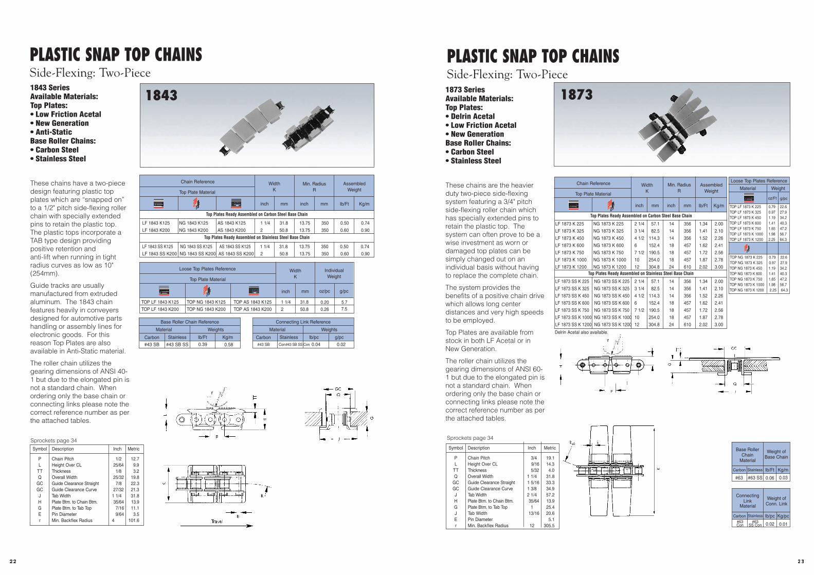
PLASTIC SNAP TOP CHAINSStraight Run: Two-Piece
863863 SeriesAvailable Materials:Top Plates:• Delrin Acetal• Low Friction Acetal• New Generation (to order)Base Roller Chains: • Carbon Steel• Stainless Steel
These chains have a heavierduty two-piece design featuringplastic top plates which are“snapped on” to a 3/4" pitchroller chain with speciallyextended pins to retain theplastic top. The system canoften prove to be a wiseinvestment as worn ordamaged top plates can besimply changed out on anindividual basis without havingto replace the complete chain.
The system provides thebenefits of a positive chaindrive which allows long centerdistances and very high speedsto be employed.
Top plates are available fromstock LF Acetal and on a madeto order basis in New Generationor Anti-Static.
The roller chain utilizes thegearing dimensions of ANSI 60-1 but due to the elongatedpin is not a standard chain.When ordering only the basechain or connecting linksplease note the correctreference number as per theattached tables.
ConnectingLink Weight of
Conn. LinkMaterial
#63SS Con
#63Con
Ib/pc Kg/pcCarbon Stainless
Sprockets page 34
D 863 K 325 LF 863 K 325 3 1/4 82.5 1.41 2.10
D 863 K 450 LF 863 K 450 4 1/2 114.3 1.50 2.23
D 863 K 600 LF 863 K 600 6 152.4 1.70 2.53
D 863 K 750 LF 863 K 750 7 1/2 190.5 1.80 2.68
D 863 SS K 325 LF 863 SS K 325 3 1/4 82.5 1.41 2.10
D 863 SS K 450 LF 863 SS K 450 4 1/2 114.3 1.50 2.23
D 863 SS K 600 LF 863 SS K 600 6 152.4 1.70 2.53
D 863 SS K 750 LF 863 SS K 750 7 1/2 190.5 1.80 2.68
Top Plate Material
inch mm Ib/Ft Kg/m
Chain Reference WidthK
AssembledWeight
Top Plates Ready Assembled on Carbon Steel Base Chain
Top Plates Ready Assembled on Stainless Steel Base Chain
TOP D 863 K 325 TOP LF 863 K 325 3 1/4 82.5 0.71 20.5
TOP D 863 K 450 TOP LF 863 K 450 4 1/2 114.3 0.92 26.4
TOP D 863 K 600 TOP LF 863 K 600 6 152.4 1.17 33.6
TOP D 863 K 750 TOP LF 863 K 750 7 1/2 190.5 1.43 40.8
Material
inch mm oz/pc g/pc
Loose Top Plates Reference WidthK
IndividualWeight
Base RollerChain Weight of
Base ChainMaterial
#63 #63 SS 0.94 1.40
0.06 0.03
Ib/Ft Kg/mCarbon Stainless
Symbol Description Inch Metric
P Chain Pitch 3/4 19.1L Height Over CL 9/16 14.3TT Plate Thickness 5/32 4.0Q Hinge Width 1 11/32 34.1GC Guide Clearance 1 7/16 36.5H Plate Btm. to Chain Btm. 3/4 19.1E Pin Diameter 6.0r Min. Backflex Radius 6 152.4
p
H
TT
L
Q
GC
E
K
r
Travel
863
22
Sprockets page 34
PLASTIC SNAP TOP CHAINSStraight Run: Two-Piece
843843 SeriesAvailable Materials:Top Plates:• Delrin Acetal• Low Friction Acetal• New Generation (to order)Base Roller Chains:• Carbon Steel• Stainless Steel
These chains have a two-piecedesign featuring plastic topplates which are “snapped on”to a 1/2" pitch roller chain withspecially extended pins toretain the plastic top. Thesystem can often prove to be awise investment as worn ordamaged top plates can besimply changed out on anindividual basis without havingto replace the complete chain.
The system provides thebenefits of a positive chaindrive which allows long centerdistances and very highspeeds to be employed.
Top Plates are available fromstock in LF Acetal and on amade to order basis in NewGeneration or Anti-Static.
The roller chain utilizes thegearing dimensions of ANSI 40-1 but due to the elongatedpin is not a standard chain.When ordering only the basechain or connecting linksplease note the correctreference number as per theattached tables.
Symbol Description Inch Metric
P Chain Pitch 1/2 12.7L Height Over CL 23/64 9.1TT Plate Thickness 1/8 3.2Q Hinge Width 13/16 20.6GC Guide Clearance 15/16 23.8H Plate Btm. to Chain Btm. 29/64 11.5E Pin Diameter 5/32 4.0r Min. Backflex Radius 6 152.4
E
K
p
H
TT
L
Q
GC
r
Travel
* D=No longer stock item.
100138144200325
100138144
200325
100138144
200325
100138144
200325
100138144200
325
100138144200
325
*
843
2322 25
PLASTIC SNAP TOP CHAINSSide-Flexing: Two-Piece
18731873 SeriesAvailable Materials:Top Plates:• Delrin Acetal• Low Friction Acetal• New GenerationBase Roller Chains:• Carbon Steel• Stainless Steel
These chains are the heavierduty two-piece side-flexingsystem featuring a 3/4" pitchside-flexing roller chain whichhas specially extended pins toretain the plastic top. Thesystem can often prove to be awise investment as worn ordamaged top plates can besimply changed out on anindividual basis without havingto replace the complete chain.
The system provides the
which allows long center
to be employed.
Top Plates are available fromstock in both LF Acetal or inNew Generation.
The roller chain utilizes thegearing dimensions of ANSI 60-1 but due to the elongated pin isnot a standard chain. Whenordering only the base chain orconnecting links please note thecorrect reference number as perthe attached tables.
H
p
GC
Q
J
Rmin E
L
G
TT
K
ConnectingLink Weight of
Conn. LinkMaterial
#63SS Con
#63Con
Ib/pc Kg/pcCarbon Stainless
Base RollerChain
Weight ofBase Chain
Material
#63 #63 SS 0.06 0.03
0.010.02
Ib/Ft Kg/mCarbon Stainless
1873
24
PLASTIC SNAP TOP CHAINSSide-Flexing: Two-Piece
18431843 SeriesAvailable Materials:Top Plates:• Low Friction Acetal• New Generation• Anti-StaticBase Roller Chains:• Carbon Steel• Stainless Steel
These chains have a two-piecedesign featuring plastic topplates which are “snapped on”to a 1/2" pitch side-flexing rollerchain with specially extendedpins to retain the plastic top.The plastic tops incorporate aTAB type design providingpositive retention and anti-lift when running in tightradius curves as low as 10"(254mm).
Guide tracks are usuallymanufactured from extrudedaluminum. The 1843 chainfeatures heavily in conveyersdesigned for automotive partshandling or assembly lines forelectronic goods. For thisreason Top Plates are alsoavailable in Anti-Static material.
The roller chain utilizes thegearing dimensions of ANSI 40-1 but due to the elongated pin isnot a standard chain. Whenordering only the base chain orconnecting links please note thecorrect reference number as perthe attached tables.
J
QGC
G
p
H
L
R
TT
K
TT
r
ETravel
1843

252427
PLASTIC FLAT TOP CHAINSMultiple-Flexing: Plate Top and Pusher Attachments
Novoflex®
Plate TopsPushers
Novoflex Plate Top ChainsNovoflex Pusher AttachmentsAvailable Materials:• White Delrin Acetal• Gray Delrin Acetal• Low Friction Acetal• Stainless Steel Pins
1702 Series Plate Top Chainsare available in two forms:
• TAB H1/H2 Series: Theextremely flat top plates havea crescent profile whichprovide a wide conveying areawith limited gaps. Minimumturn radius can still beachieved by utilizing thesmaller width H1 series. Thesechains feature a uniquecentral TAB guide systemwhich provides stability and isideal for aluminum profileconveyor systems.
• TAB P1/P2 Series: Thesechains feature an overlappingtop plate system whichprovides maximum operatorsecurity. As with the H seriesthe chains feature a uniquecentral TAB guide system forstability when installed inAluminum profile guides.
Novoflex 1700 Series/Pusher AttachmentsM1/M2/M3 M series attachments areavailable in three sizes providinga wide range of solutions forproducts which need to bepushed or carried. Theattachments are assembledaccording to customerrequirement (e.g. M1 every 4thpitch).
The M3 attachment is a solid unitmanufactured from a chemicalresistant Polyamide offering highload capacity. Is particularlyused in crate washing systemswhich demand hightemperatures, often combinedwith New Generation link platematerial which can operate up to250° F (120° C).
h
p
R
E h1
J
TT
L
KQ
G
h
p
R
Q
E h1
J
TT
L G
K
Novoflex1702 TAB H1 /H2
Novoflex1702 TAB P1 /P2
M1 /M2 /M3
h
pE
H
M1
d d
d
M2 M3
1702 M1 1701 TAB M1 M 1 Acetal 4 1/32 102.00 13/32 10.50 1.75 50.0
1702 M2 1702 TAB M2 M 2 Acetal 1 21/32 42.00 17/32 13.50 1.05 30.0
1702 M3 1701 TAB M3 NG 1702 M3 1701TAB M3 M 3 Polyamide 1 3/16 30.00 31/64 12.00 1.75 50.0
Material of Basic ChainD (White) LF (Brown)
Type Material inch mminch mm oz/pc g/pc
1700 Pusher Attachment Series Reference Pusher Reference
Pusher Material
Diameterd
HeightH
Weight
Green Green
r
r
Symbol Description Inch Metric
P Chain Pitch 1.96 50.0
L Height Over CL 7/8 22.5
h1 Tab Height 3/16 8.0
Q Width 2 11/64 55.0
J Tab Width 21/32 67.5
h Height 15/16 24.0
G Chain Btm. to Tab Top 3/4 15.5
E Pin Diameter 3/16 8.0
r Min. Backflex Radius 70 7/8 1800.0
Symbol Description Inch Metric
P Chain Pitch 1.96 50.0
L Height Over CL 27/32 21.5
h1 Tab Height 3/16 8.0
Q Width 2 11/64 55.0
J Tab Width 21/32 67.5
h Height 15/16 24.0
G Chain Btm. to Tab Top 25/64 15.5
E Pin Diameter 3/16 8.0
r Min. Backflex Radius 70 7/8 1800.0Travel
Plate TopsPushers
17001701 TAB1702
Chain No.Pitch
Pin. mm.
WidthW
in. mm.
Diameterof Pin
Din. mm.
Depthof Sidebar
Hin. mm.
OverallwidthW1
in. mm.
Heightof D Lug
Tin. mm.
CM600CM 600DCM 1300CM 1300D
2.52 642.52 643.25 833.25 83
11116 43
11116 43
2116 52
2116 52
716 11
716 11
916 14
916 14
118 29
118 29
112 38
112 38
- -21
8 54- -
21116 68
- -9
16 14- -
1516 24
272628
Symbol Description Inch Metric
Dimensions for 600 Series Chains
L Height Over CL 9/16 14.3W Width over Pin 1 21/32 42.0J Width over TAB 2 1/8 54.0
LH Height of TAB 43/64 17.0
Dimensions for 1400 Series Chains
L Height Over CL 3/4 19.3W Width over Pin 1 31/32 50.0J Width over TAB 2 37/64 65.5
LH Height of TAB 49/64 19.5
Dimensions for 600 Series Sprockets
B Tooth Width 0.34 8.7W Width 2.00 50.0A Hub Diameter 3.70 95.0db Stock Bore 0.75 20.0
Dimensions for 1400 Series Sprockets
B Tooth Width 0.68 17.5W Width 2.50 63.5A Hub Diameter 3.90 100.0db Stock Bore 0.75 20.0
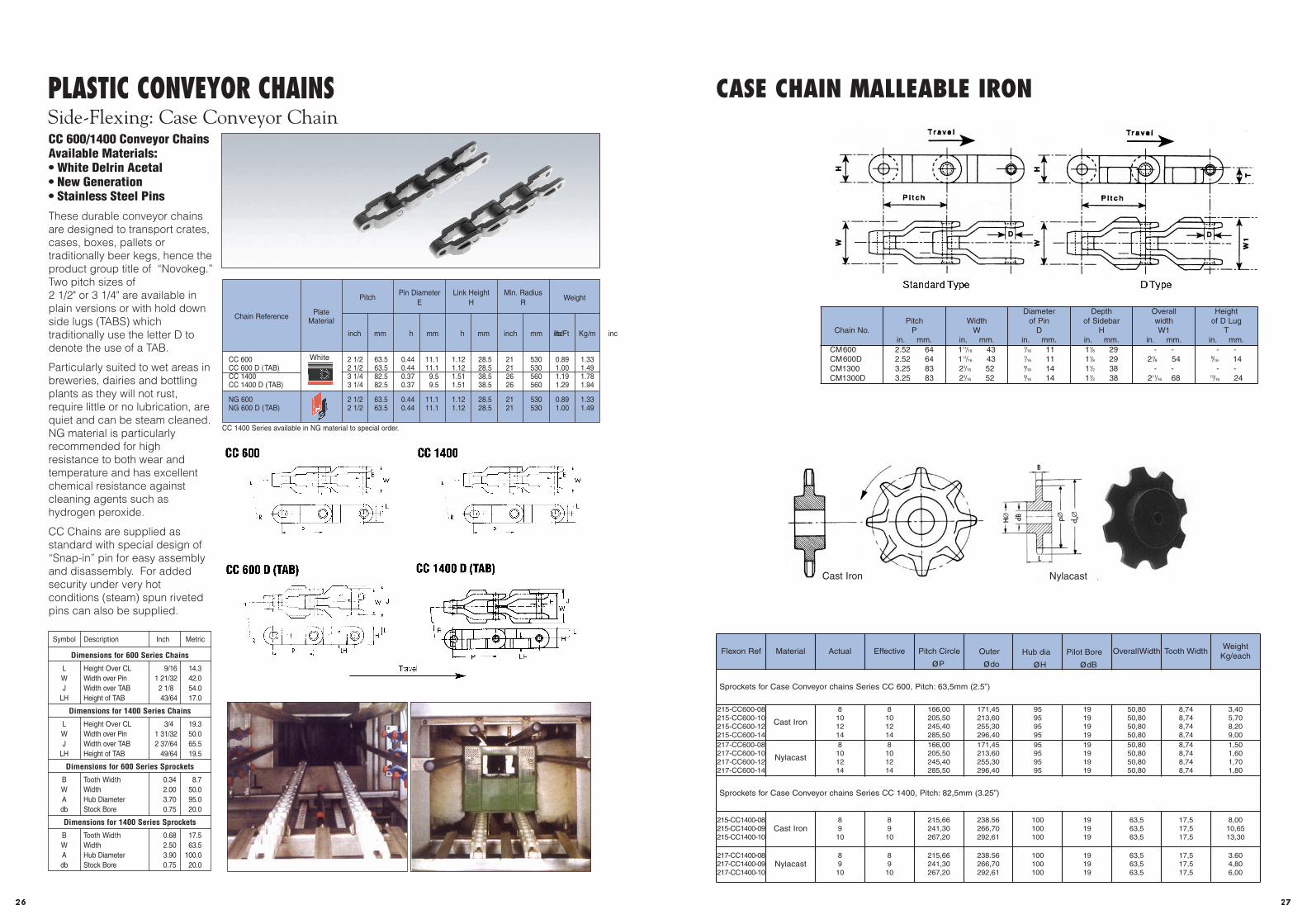
PLASTIC CONVEYOR CHAINSSide-Flexing: Case Conveyor ChainCC 600/1400 Conveyor ChainsAvailable Materials:• White Delrin Acetal• New Generation• Stainless Steel Pins
These durable conveyor chainsare designed to transport crates,cases, boxes, pallets ortraditionally beer kegs, hence theproduct group title of “Novokeg.”Two pitch sizes of 2 1/2" or 3 1/4" are available inplain versions or with hold downside lugs (TABS) whichtraditionally use the letter D todenote the use of a TAB.
Particularly suited to wet areas inbreweries, dairies and bottlingplants as they will not rust,require little or no lubrication, arequiet and can be steam cleaned.NG material is particularlyrecommended for highresistance to both wear andtemperature and has excellentchemical resistance againstcleaning agents such ashydrogen peroxide.
CC Chains are supplied asstandard with special design of“Snap-in” pin for easy assemblyand disassembly. For addedsecurity under very hotconditions (steam) spun rivetedpins can also be supplied.
EW
H
P
R
L
EW
H
P
R
L
CC 600
EW
H
P
R
OW
LH
L
CC 600 D (TAB)
CC 1400
CC 1400 D (TAB)
CC 600 2 1/2 63.5 0.44 11.1 1.12 28.5 21 530 0.89 1.33CC 600 D (TAB) 2 1/2 63.5 0.44 11.1 1.12 28.5 21 530 1.00 1.49CC 1400 3 1/4 82.5 0.37 9.5 1.51 38.5 26 560 1.19 1.78CC 1400 D (TAB) 3 1/4 82.5 0.37 9.5 1.51 38.5 26 560 1.29 1.94
NG 600 2 1/2 63.5 0.44 11.1 1.12 28.5 21 530 0.89 1.33NG 600 D (TAB) 2 1/2 63.5 0.44 11.1 1.12 28.5 21 530 1.00 1.49
Chain Reference PlateMaterial
Pitch
mminch mm inch mm inch mm inch
Min. RadiusR
Link HeightH
Pin DiameterE
Kg/mIb/Ft
Weight
J E
P
R
LH
H
WJ
L
LL
White
CC 1400 Series available in NG material to special order.
Travel
Standard Type D Type
CASE CHAIN MALLEABLE IRON
Flexon Ref Material Actual Effective Pitch Circle
øP
Overall Width Tooth WidthWeight
Kg/each
Sprockets for Case Conveyor chains Series CC 600, Pitch: 63,5mm (2.5”)
215-CC600-08215-CC600-10215-CC600-12215-CC600-14
Cast Iron
8101214
8101214
166,00205,50245,40285,50
171,45213,60255,30296,40
95959595
19191919
50,8050,8050,8050,80
8,748,748,748,74
3,405,708,209,00
217-CC600-08217-CC600-10217-CC600-12217-CC600-14
Nylacast
8101214
8101214
166,00205,50245,40285,50
171,45213,60255,30296,40
95959595
19191919
50,8050,8050,8050,80
8,748,748,748,74
1,501,601,701,80
Sprockets for Case Conveyor chains Series CC 1400, Pitch: 82,5mm (3.25”)
215-CC1400-08215-CC1400-09215-CC1400-10
Cast Iron8910
8910
215,66241,30267,20
238.56266,70292,61
100100100
191919
63,563,563,5
17,517,517,5
8,0010,6513,30
217-CC1400-08217-CC1400-09217-CC1400-10
Nylacast8910
8910
215,66241,30267,20
238.56266,70292,61
100100100
191919
63,563,563,5
17,517,517,5
3.604,806,00
Outer
ødo
Hub dia
øH
Pilot Bore
ødB
Cast Iron Nylacast
292831
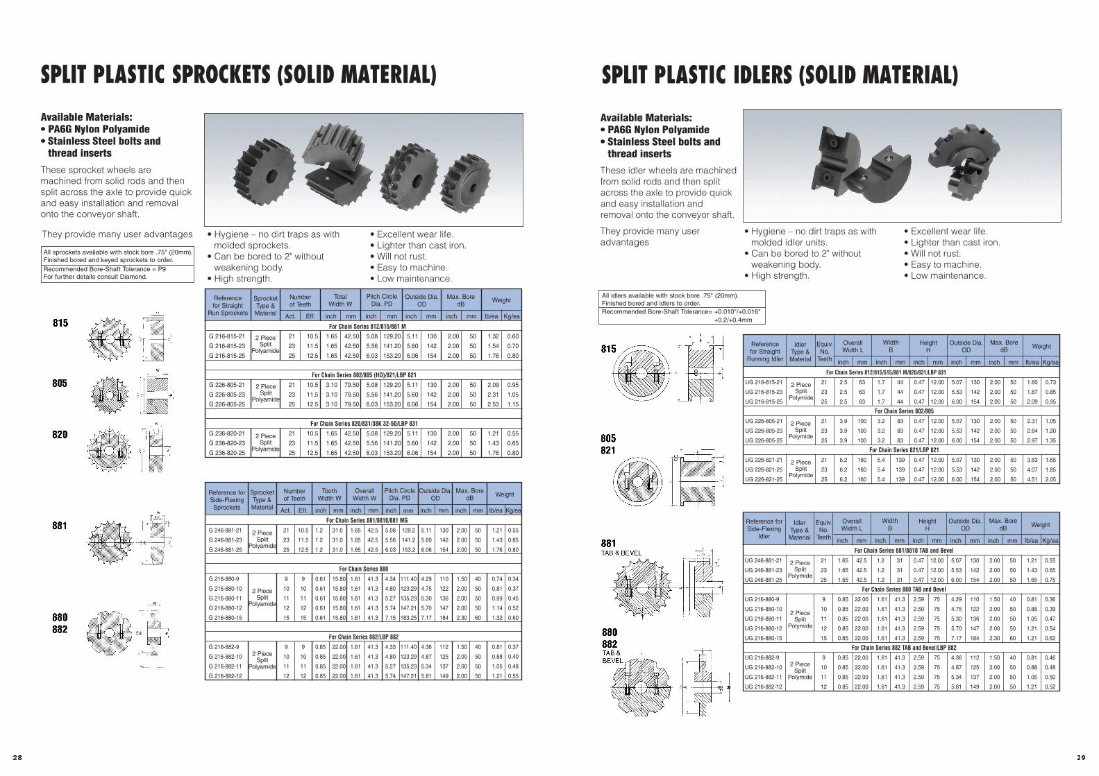
SPLIT PLASTIC IDLERS (SOLID MATERIAL)
Novopart®Available Materials:• PA6G Nylon Polyamide• Stainless Steel bolts and
thread inserts
These idler wheels are machined from solid rods and then splitacross the axle to provide quickand easy installation andremoval onto the conveyor shaft.
They provide many useradvantages
For Chain Series 812/815/515/881 M/820/831/LBP 831
UG 216-815-21 21 2.5 63 1.7 44 0.47 12.00 5.07 130 2.00 50 1.60 0.73
UG 216-815-23 23 2.5 63 1.7 44 0.47 12.00 5.53 142 2.00 50 1.87 0.85
UG 216-815-25 25 2.5 63 1.7 44 0.47 12.00 6.00 154 2.00 50 2.09 0.95
For Chain Series 802/805
UG 226-805-21 21 3.9 100 3.2 83 0.47 12.00 5.07 130 2.00 50 2.31 1.05
UG 226-805-23 23 3.9 100 3.2 83 0.47 12.00 5.53 142 2.00 50 2.64 1.20
UG 226-805-25 25 3.9 100 3.2 83 0.47 12.00 6.00 154 2.00 50 2.97 1.35
For Chain Series 821/LBP 821
UG 226-821-21 21 6.2 160 5.4 139 0.47 12.00 5.07 130 2.00 50 3.63 1.65
UG 226-821-25 23 6.2 160 5.4 139 0.47 12.00 5.53 142 2.00 50 4.07 1.85
UG 226-821-25 25 6.2 160 5.4 139 0.47 12.00 6.00 154 2.00 50 4.51 2.05
Referencefor Straight
Running Idler inch mm inch mm inch mm Ib/ea Kg/ea
IdlerType & Material
Equiv.No.
Teeth
OverallWidth L
inch mm
WidthB
inch mm
HeightH
Outside Dia.OD
Max. BoredB Weight
For Chain Series 881/8810 TAB and Bevel
UG 246-881-21 21 1.65 42.5 1.2 31 0.47 12.00 5.07 130 2.00 50 1.21 0.55
UG 246-881-23 23 1.65 42.5 1.2 31 0.47 12.00 5.53 142 2.00 50 1.43 0.65
UG 246-881-25 25 1.65 42.5 1.2 31 0.47 12.00 6.00 154 2.00 50 1.65 0.75
For Chain Series 880 TAB and Bevel
UG 216-880-9 9 0.85 22.00 1.61 41.3 2.59 75 4.29 110 1.50 40 0.81 0.36
UG 216-880-10 10 0.85 22.00 1.61 41.3 2.59 75 4.75 122 2.00 50 0.88 0.39
UG 216-880-11 11 0.85 22.00 1.61 41.3 2.59 75 5.30 136 2.00 50 1.05 0.47
UG 216-880-12 12 0.85 22.00 1.61 41.3 2.59 75 5.70 147 2.00 50 1.21 0.54
UG 216-880-15 15 0.85 22.00 1.61 41.3 2.59 75 7.17 184 2.30 60 1.21 0.62
For Chain Series 882 TAB and Bevel/LBP 882
UG 216-882-9 9 0.85 22.00 1.61 41.3 2.59 75 4.36 112 1.50 40 0.81 0.46
UG 216-882-10 10 0.85 22.00 1.61 41.3 2.59 75 4.87 125 2.00 50 0.88 0.48
UG 216-882-11 11 0.85 22.00 1.61 41.3 2.59 75 5.34 137 2.00 50 1.05 0.50
UG 216-882-12 12 0.85 22.00 1.61 41.3 2.59 75 5.81 149 2.00 50 1.21 0.52
Reference forSide-Flexing
Idlerinch mm inch mm inch mm Ib/ea Kg/ea
IdlerType &Material
Equiv.No.
Teeth
OverallWidth L
inch mm
WidthB
inch mm
HeightH
Outside Dia.OD
Max. BoredB Weight
d B
LB
H
D
d Bd fd o
LB
H
• Hygiene – no dirt traps as with molded idler units.
• Can be bored to 2" without weakening body.
• High strength.
• Excellent wear life.• Lighter than cast iron.• Will not rust.• Easy to machine.• Low maintenance.
All idlers available with stock bore .75" (20mm).Finished bored and idlers to order.Recommended Bore-Shaft Tolerance= +0.010"/+0.016"
+0.2/+0.4mm
815
805821
881TAB & BEVEL
880882TAB &BEVEL
DO
2 PieceSplit
Polymide
2 PieceSplit
Polymide
2 PieceSplit
Polymide
2 PieceSplit
Polymide
2 PieceSplit
Polymide
2 PieceSplit
PolymideD
O
Bd H
d B
LB
H
D
d Bd fd o
LB
H
30
SPLIT PLASTIC SPROCKETS (SOLID MATERIAL)
Novopart®Available Materials:• PA6G Nylon Polyamide• Stainless Steel bolts and
thread inserts
These sprocket wheels aremachined from solid rods and thensplit across the axle to provide quickand easy installation and removalonto the conveyor shaft.
d BDPD
O
W
d B
W
DPD
O
d B
TW
57. 02
DPD
O
d B
W
DPDO
TW
d B
W
DPD
O
For Chain Series 812/815/881 M
G 216-815-21 21 10.5 1.65 42.50 5.08 129.20 5.11 130 2.00 50 1.32 0.60
G 216-815-23 23 11.5 1.65 42.50 5.56 141.20 5.60 142 2.00 50 1.54 0.70
G 216-815-25 25 12.5 1.65 42.50 6.03 153.20 6.06 154 2.00 50 1.76 0.80
For Chain Series 802/805 (HD)/821/LBP 821
G 226-805-21 21 10.5 3.10 79.50 5.08 129.20 5.11 130 2.00 50 2.09 0.95
G 226-805-23 23 11.5 3.10 79.50 5.56 141.20 5.60 142 2.00 50 2.31 1.05
G 226-805-25 25 12.5 3.10 79.50 6.03 153.20 6.06 154 2.00 50 2.53 1.15
For Chain Series 820/831/38K 32-50/LBP 831
G 236-820-21 21 10.5 1.65 42.50 5.08 129.20 5.11 130 2.00 50 1.21 0.55
G 236-820-23 23 11.5 1.65 42.50 5.56 141.20 5.60 142 2.00 50 1.43 0.65
G 236-820-25 25 12.5 1.65 42.50 6.03 153.20 6.06 154 2.00 50 1.76 0.80
Act. Eff. inch mm inch mm inch mm inch mm Ib/ea Kg/ea
SprocketType &Material
Numberof Teeth
TotalWidth W
Pitch CircleDia. PD
Outside Dia.OD
Max. BoredB
Weight
For Chain Series 881/8810/881 MG
G 246-881-21 21 10.5 1.2 31.0 1.65 42.5 5.08 129.2 5.11 130 2.00 50 1.21 0.55
G 246-881-23 23 11.5 1.2 31.0 1.65 42.5 5.56 141.2 5.60 142 2.00 50 1.43 0.65
G 246-881-25 25 12.5 1.2 31.0 1.65 42.5 6.03 153.2 6.06 154 2.00 50 1.76 0.80
For Chain Series 880
G 216-880-9 9 9 0.61 15.80 1.61 41.3 4.34 111.40 4.29 110 1.50 40 0.74 0.34
G 216-880-10 10 10 0.61 15.80 1.61 41.3 4.80 123.29 4.75 122 2.00 50 0.81 0.37
G 216-880-11 11 11 0.61 15.80 1.61 41.3 5.27 135.23 5.30 136 2.00 50 0.99 0.45
G 216-880-12 12 12 0.61 15.80 1.61 41.3 5.74 147.21 5.70 147 2.00 50 1.14 0.52
G 216-880-15 15 15 0.61 15.80 1.61 41.3 7.15 183.25 7.17 184 2.30 60 1.32 0.60
For Chain Series 882/LBP 882
G 216-882-9 9 9 0.85 22.00 1.61 41.3 4.33 111.40 4.36 112 1.50 40 0.81 0.37
G 216-882-10 10 10 0.85 22.00 1.61 41.3 4.80 123.29 4.87 125 2.00 50 0.88 0.40
G 216-882-11 11 11 0.85 22.00 1.61 41.3 5.27 135.23 5.34 137 2.00 50 1.05 0.48
G 216-882-12 12 12 0.85 22.00 1.61 41.3 5.74 147.21 5.81 149 2.00 50 1.21 0.55
Act. Eff. inch mm inch mm inch mm inch mm Ib/ea Kg/ea
SprocketType &Material
Numberof Teeth
ToothWidth W
inch mm
OverallWidth W
Pitch CircleDia. PD
Outside Dia.OD
Max. BoredB Weight
• Hygiene – no dirt traps as with molded sprockets.
• Can be bored to 2" without weakening body.
• High strength.
• Excellent wear life.• Lighter than cast iron.• Will not rust.• Easy to machine.• Low maintenance.
They provide many user advantages
815
805
820
881
880882
w
w
w
w
All sprockets available with stock bore .75" (20mm).Finished bored and keyed sprockets to order.Recommended Bore-Shaft Tolerance = P9For further details consult Diamond.
2 PieceSplit
Polyamide
2 PieceSplit
Polyamide
2 PieceSplit
Polyamide
2 PieceSplit
Polyamide
2 PieceSplit
Polyamide
2 PieceSplit
Polyamide
Referencefor Straight
Run Sprockets
Reference forSide-FlexingSprockets

3130
Sprockets for Series 820/831 Pitch 38,1 mm = 11/2”
Steel and Polyamide Cast Iron
Sprockets for Series 880 Pitch 38,1 mm = 11/2”
Sprockets for Series 882 Pitch 38,1 mm = 11/2”
d B d f d 0
16,5
41,3
42,5 42,5
22 22
d B d f d 0
10°
14
42,5 42,5
41,3
15,8
16,510°
14
d B d f d 0 d B d f d 0
15,8
d B d f d 0 d B d f d 0
214-880- 9214-880-10214-880-11214-880-12214-880-15
Steel
910111215
910111215
111,40123,29135,23147,21183,25
110122136147184
95,80107,70119,60131,60167,60
2020202020
6060606060
1,381,561,761,982,80
215-880- 9215-880-10215-880-11215-880-12215-880-15
Cast Iron
910111215
910111215
111,40123,29135,23147,21183,25
110122136147184
95,80107,70119,60131,60167,60
2020202020
4545454545
1,301,401,501,601,90
216-880- 9216-880-10216-880-11216-880-12216-880-15
Polyamid
910111215
910111215
111,40123,29135,23147,21183,25
110122136147184
95,80107,70119,60131,60167,60
2020202020
6060606060
0,340,380,440,510,80
214-882- 9214-882-10214-882-11214-882-12
Steel
9101112
9101112
111,40123,29135,23147,21
112125137149
91,35103,73115,67127,66
20202020
60606060
1,411,671,952,26
215-882- 9215-882-10215-882-11215-882-12
Cast Iron
9101112
9101112
111,40123,29135,23147,21
112125137149
91,35103,73115,67127,66
20202020
45454545
1,701,902,002,10
216-882- 9216-882-10216-882-11216-882-12
Polyamid
9101112
9101112
111,40123,29135,23147,21
112125137149
91,35103,73115,67127,66
20202020
60606060
0,440,460,480,50
FlexonRef
MaterialNo. of Teeth
Actual Effective
PitchCircle
øOuterø do
Rootø df
PilotBoreø dB
MaxBore
ø
Weightkg/each
234-820-19234-820-21234-820-23234-820-25
Steel
19212325
9,5010,5011,5012,50
117,30129,20141,20153,20
117130142154
104,17116,07128,07140,07
20202020
60677580
2,202,733,343,99
235-820-19235-820-21235-820-23235-820-25
Cast Iron
19212325
9,5010,5011,5012,50
117,30129,20141,20153,20
117130142154
104,17116,07128,07140,07
20202020
32454550
1,501,802,002,10
236-820-17236-820-19236-820-21236-820-23236-820-25
Polyamid
1719212325
8,509,50
10,5011,5012,50
105,50117,30129,20141,20153,20
105117130142154
92,37104,17116,07128,07140,07
2020202020
5560677580
0,300,400,500,600,75
236-820 234-820 216-880 215-882
d B d f d 0
16,5
41,3
42,5 42,5
22 22
d B d f d 0
10°
14
42,5 42,5
41,3
15,8
16,510°
14
d B d f d 0 d B d f d 0
15,8
d B d f d 0 d B d f d 0
STANDARD SPROCKETS IN STEEL/CAST IRON/PLASTIC
FlexonRef
MaterialNo. of Teeth
Actual Effective
PitchCircle
øOuterø do
Rootø df
PilotBoreø dB
MaxBore
ø
Weightkg/each
214-815-19214-815-21214-815-23214-815-25
Steel
19212325
9,5010,5011,5012,50
117,30129,20141,20153,20
117130142154
104,17116,07128,07140,07
20202020
60677580
3,504,285,136,06
215-815-19215-815-21215-815-23215-815-25
Cast Iron
19212325
9,5010,5011,5012,50
117,30129,20141,20153,20
117130142154
104,17116,07128,07140,07
20202020
32454550
2,302,502,602,80
216-815-17216-815-19216-815-21216-815-23216-815-25
Polyamid
1719212325
8,509,50
10,5011,5012,50
105,50117,30129,20141,20153,20
105117130142154
92,37104,17116,07128,07140,07
2020202020
5560677580
0,300,400,500,600,70
Series 812/815/881M/800/802/805/881/8810/881 MF and 821
Sprockets for Series 812/815/881 M Pitch 38,1 mm = 11/2”
Steel and Polyamide Cast Iron
Sprockets for Series 800/802/805/821 Pitch 38,1 mm = 11/2”
Sprockets for Series 881/8810/881 MF Pitch 38,1 mm = 11/2”
Ø d
o
Ø d
f
Ø d
B
Ø d
B
Ø d
f
Ø d
o
d o d f d B d B d f d o
d 0 d f d B d B d f d o
42,5 42,5
79,4 79,4
41
42,5 42,5
3131
224-805-19224-805-21224-805-23224-805-25
Steel
19212325
9,5010,5011,5012,50
117,30129,20141,20153,20
117130142154
104,17116,07128,07140,07
20202020
60677580
6,638,099,6811,42
225-805-19225-805-21225-805-23225-805-25
Cast Iron
19212325
9,5010,5011,5012,50
117,30129,20141,20153,20
117130142154
104,17116,07128,07140,07
20202020
32454550
2,903,003,203,30
226-805-17226-805-19226-805-21226-805-23226-805-25
Polyamid
1719212325
8,509,50
10,5011,5012,50
105,50117,30129,20141,20153,20
105117130142154
92,37104,17116,07128,07140,07
2020202020
5560677580
0,600,700,800,901,00
244-881-19244-881-21244-881-23244-881-25
Steel
19212325
9,5010,5011,5012,50
117,30129,20141,20153,20
117130142154
104,17116,07128,07140,07
20202020
60677580
3,143,844,615,44
245-881-19245-881-21245-881-23245-881-25
Cast Iron
19212325
9,5010,5011,5012,50
117,30129,20141,20153,20
117130142154
104,17116,07128,07140,07
20202020
32454550
1,701,902,102,30
246-881-17246-881-19246-881-21246-881-23246-881-25
Polyamid
1719212325
8,509,50
10,5011,5012,50
105,50117,30129,20142,00153,20
105117130142154
92,37104,10116,00128,00140,00
2020202020
5560677580
0,350,400,450,500,55
215-815 226-805 244-881216-815
Ø d
o
Ø d
f
Ø d
B
Ø d
B
Ø d
f
Ø d
o
d o d f d B d B d f d o
d 0 d f d B d B d f d o
42,5 42,5
79,4 79,4
41
42,5 42,5
3131
Ø d
o
Ø d
f
Ø d
B
Ø d
B
Ø d
f
Ø d
o
d o d f d B d B d f d o
d 0 d f d B d B d f d o
42,5 42,5
79,4 79,4
41
42,5 42,5
3131
Ø d
o
Ø d
f
Ø d
B
Ø d
B
Ø d
f
Ø d
o
d o d f d B d B d f d o
d 0 d f d B d B d f d o
42,5 42,5
79,4 79,4
41
42,5 42,5
3131
Ø d
o
Ø d
f
Ø d
B
Ø d
B
Ø d
f
Ø d
o
d o d f d B d B d f d o
d 0 d f d B d B d f d o
42,5 42,5
79,4 79,4
41
42,5 42,5
3131
Ø d
o
Ø d
f
Ø d
B
Ø d
B
Ø d
f
Ø d
o
d o d f d B d B d f d o
d 0 d f d B d B d f d o
42,5 42,5
79,4 79,4
41
42,5 42,5
3131
STANDARD SPROCKETS IN STEEL/CAST IRON/PLASTIC

32
Compact curves provide a fast andtrouble free solution to conveyorbuilding.Produced from Polyethylene UHMWPE 1000 to consistently guarantee aperfect radius and clearancebetween the chain. The materialdoes not absorb moisture thuspreventing expansion andpossibility of “trapping” chain.UHMW PE 1000 is also highly wearresistant and noise absorbing.
Guide Sections are also available instraight running form.Standard length=2 meters.
Order Example (per Set)Double strand bevel design for 880-K-450R1=610 mm, R2=730 mmincorporating two strands within two curvesections-top and return run-plus cover plate forretaining return run
Order No.
Single & multi-track straightsections for sideflexingtable top chains available intwo meter lengths asstandard.
Compact Curve Sections (Dimensions in mm) StraightSections
FlexonRef:
Chain Type Width WidthA1
Guide TrackWidth
B1 (+-0,5) B2 H1Widths
H2 H3 H4Radius
R1
CentreDistance
EFlexon
Ref:KS 013500...KS 018610...KS 030610...
880/881/8810880/881/8810
881/8810
K 325K 450K 750
100125200
41,4 - 25 18 - 16500610610
90120195
SKS 013-00...SKS 018-00...SKS 030-00...
KT 013500...KT 018610...KT 030610...
880/881/8810TAB880/881/8810TAB
881/8810TAB
K 325K 450K 750
100125200
44 70 25 18 9,5 -500610610
90120195
SKT 013-00...SKT 018-00...SKT 030-00...
KS 218610...KS 230610...KS 240610...
882882882
K 450K 750
K 1000
125200265
58 - 28 22 - 16610610610
120195260
SKS 218-00...SKS 018-00...SKS 240-00...
TS 218610...TS 230610...TS 240610...TS 248610...
882TAB882TAB882TAB882TAB
K 450K 750
K 1000K1200
125200265320
58 90 32 26 16 -
610610610610
120195260310
SKT 218-00...SKT 230-00...SKT 240-00...SKT 248-00...
TS 313500...TS 318610...TS 324610...TS 330610...TS 340610...TS 348610...
187318731873187318731873
K 325K 450K 600K 750
K 1000 K 1200
100125160200265320
34,6 70 36 29 19 -
500500610610610610
90120160195260310
SKT 313-00...SKT 318-00...SKT 324-00...SKT 330-00...SKT 340-00...SKT 348-00...
KS 018 610 ...2 (610/730)
Bevel design
Code no. for chain type(see below table)
Radius R1
No. ofstrands required
R1/R2 only formultistrand order
COMPACT CURVE AND STRAIGHT GUIDING SECTIONS
BEVEL Design TAB Design
Dimensions H5 = Clearance=Top Plate Thickness of Chain + 1.5 mm
Mounting 1=M8X15 Nut Insert 2=M8 Countersunk HoleInformation:
BEVEL Design TAB Design
BEVEL Design TAB Design
Single Strand
Double Strand
Triple Strand
1
2
1
2
2
1 1
2
2
1
2
1
33
COMPACT CURVE AND STRAIGHT GUIDING SECTIONS
3534
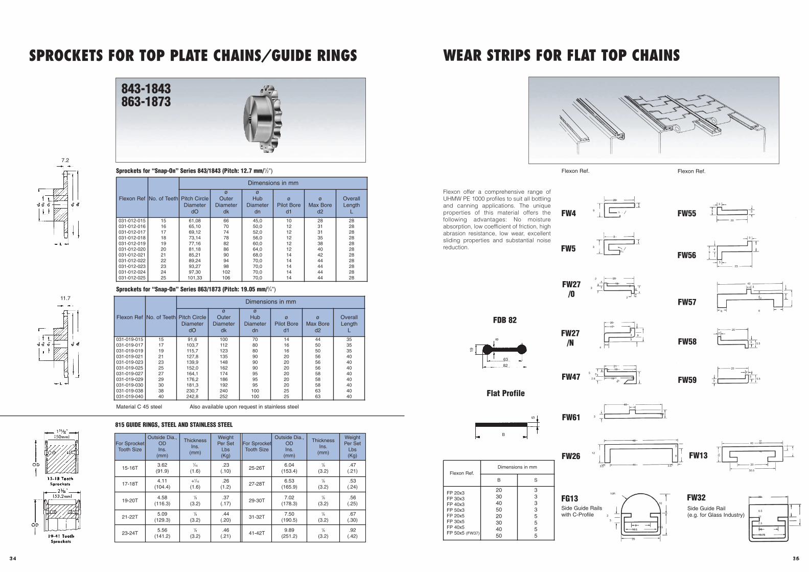
Sprockets for “Snap-On” Series 843/1843 (Pitch: 12.7 mm/1/2”)
Flexon Ref No. of Teeth
Dimensions in mm
Pitch CircleDiameter
dO
øOuter
Diameterdk
øHub
Diameterdn
øPilot Bore
d1
øMax Bore
d2
OverallLength
L
031-012-015031-012-016031-012-017031-012-018031-012-019031-012-020031-012-021031-012-022031-012-023031-012-024031-012-025
1516171819202122232425
61,0865,1069,1273,1477,1681,1885,2189,2493,2797,30101,33
667074788286909498102106
45,050,052,056,060,064,068,070,070,070,070,0
1012121212121414141414
2831313538404244444444
2828282828282828282828
Flexon Ref No. of Teeth
Dimensions in mm
Pitch CircleDiameter
dO
øOuter
Diameterdk
øHub
Diameterdn
øPilot Bore
d1
øMax Bore
d2
OverallLength
L
031-019-015031-019-017031-019-019031-019-021031-019-023031-019-025031-019-027031-019-029031-019-030031-019-038031-019-040
1517192123252729303840
91,6103,7115,7127,8139,9152,0164,1176,2181,3230,7242,8
100112123135148162174186192240252
708080909090959595100100
1416162020202020202525
4450505656565858586363
3535354040404040404040
Sprockets for “Snap-On” Series 863/1873 (Pitch: 19.05 mm/3/4”)
Material C 45 steel Also available upon request in stainless steel
11.7
7.2
843-1843863-1873
815 GUIDE RINGS, STEEL AND STAINLESS STEEL
SPROCKETS FOR TOP PLATE CHAINS/GUIDE RINGS
For SprocketTooth Size
Outside Dia.,ODIns.
(mm)
ThicknessIns.
(mm)
WeightPer Set
Lbs(Kg)
For SprocketTooth Size
Outside Dia.,ODIns.
(mm)
ThicknessIns.
(mm)
WeightPer Set
Lbs(Kg)
15-16T3.62
(91.9)
1/16
(1.6).23
(.10)25-26T
6.04(153.4)
1/8
(3.2).47
(.21)
17-18T4.11
(104.4)+1/16
(1.6).26
(1.2)27-28T
6.53(165.9)
1/8
(3.2).53
(.24)
19-20T4.58
(116.3)
1/8
(3.2).37
(.17)29-30T
7.02(178.3)
1/8
(3.2).56
(.25)
21-22T5.09
(129.3)
1/8
(3.2).44
(.20)31-32T
7.50(190.5)
1/8
(3.2).67
(.30)
23-24T5.56
(141.2)
1/8
(3.2).46
(.21)41-42T
9.89(251.2)
1/8
(3.2).92
(.42)
FW4
Side Guide Railswith C-Profile
Flexon offer a comprehensive range ofUHMW PE 1000 profiles to suit all bottlingand canning applications. The uniqueproperties of this material offers thefollowing advantages: No moistureabsorption, low coefficient of friction, highabrasion resistance, low wear, excellentsliding properties and substantial noisereduction.
Flexon Ref.Dimensions in mm
B S
FP 20x3FP 30x3FP 40x3FP 50x3FP 20x5FP 30x5FP 40x5FP 50x5 (FW37)
2030405020304050
33335555
FW5
FW55
FW56
FW27/0
FW27/N
FW57
FW58
FW59FW47
FW61
FW26 FW13
FW32FG13Side Guide Rail(e.g. for Glass Industry)
FDB 82
Flat Profile
19
8
63
82
B
S
20
9
3
1/8
3
5 3
20
94
3
3
23
433
3
412
66
220
3 5.5
3
202
35.5
10
40
20
30.5
3.57
20
9.5
16.75
6.5
2
2.5
11
10
11.5
10R
2
3
9
16.5
20
12
41
48
3
9
3.53.5
35.5
40
5 3
2.6
2119
1945
8
20
173
3
3
4
9
20
182
7
2
3
2
3
3
3
33/16
Flexon Ref. Flexon Ref.
WEAR STRIPS FOR FLAT TOP CHAINS

3734
CORROSION RESISTANCE TABLEFor Chains and Wearstrips
Chemical orCommon Term
of Conveyed Medium
Carbon SteelS 815 SS 802
SS 812
Stainless Steel Plastic
SSE 805/SSC 805SSE 815/SSC 815
SSE 881O/SSC 881
SSA 815SSA 881
NBRRubber
AcetalD/LF/AS/ELF NG
AR(Acid
Resistant)
WearstripsPE 1000
+ = Excellent resistance• = Satisfactory resistance– = Unsatisfactory resistance
Sewage Water with Sulphur – •• + + – – •• + ••
Ammonia – + + + + + •• + +
Apple Wine – + + + + + + + +
Acetone – + + + – + – + +
Petrol + + + + – + + – •
Benzol (Benzene) + + + + • + + + +
Beer • + + + + + + + +
Butyric Acid – + + + – – + + –
Chlorhydric Acid – • • • – – – + –
Vinegar – • • • – – + + +
Acetic Acid (up to 5%) – – • • – • • + +
Formaldehyde + + + + – + + + +
Fruit Juices – + + + – + + + +
Vegetable Juices • + + + – + + + +
Carbolic Acid – – • • – – – + •
Cheese – + + + – – + + –
Liqueur – + + + – + – + +
Lemonade, Mineral Water – + + + + + + + +
Milk – + + + – + + + +
Lactic Acid – – • • – + • + +
Common Salt – – • • – + + + +
Oil + + + + – + + + +
Paraffin + + + + – + + + +
Petroleum, Crude Oil – + + + – + + – –
Phosphoric Acid (up to 10%) – – • • – – • + +
Nitric Acid – • + + • – – + +
Brine – – • • – – + + –
Hydrochloric Acid (up to 2%) – – – – – – • + +
Chocolate – + + + + + + + +
Sulphuric Acid – – • • – – – + +
Mustard – + + + + – • + –
Soft drinks + + + + + + + + +
Spirits + + + + + + + + +
Carbon Tetrachloride • • • • • + • –
Water and Soap • + + + + + + + •
Water – + + + – + + + +
Hydrogen Peroxide – • + + • – + + •
Wine • + + + • + + + +
Tartaric Acid – • + + – • + + •
Lemon Juice – • + + – + + + +
Citric Acid – • + + – + + + +
Sugar Solution – • + + – + + + +
34
CORROSION RESISTANCE TABLEFor Chains and Wearstrips
Chemical orCommon Term
of Conveyed Medium
Carbon SteelS 815 SS 802
SS 812
Stainless Steel Plastic
SSE 805/SSC 805SSE 815/SSC 815
SSE 881O/SSC 881
SSA 815SSA 881
NBRRubber
AcetalD/LF/AS/ELF NG
AR(Acid
Resistant)
WearstripsPE 1000
+ = Excellent resistance•• = Satisfactory resistance– = Unsatisfactory resistance
Sewage Water with Sulphur – • + + – – • + •
Ammonia – + + + + + • + +
Apple Wine – + + + + + + + +
Acetone – + + + – + – + +
Petrol + + + + – + + – •
Benzol (Benzene) + + + + • + + + +
Beer • + + + + + + + +
Butyric Acid – + + + – – + + –
Chlorhydric Acid – • • • – – – + –
Vinegar – • • • – – + + +
Acetic Acid (up to 5%) – – • • – • • + +
Formaldehyde + + + + – + + + +
Fruit Juices – + + + – + + + +
Vegetable Juices • + + + – + + + +
Carbolic Acid – – • • – – – + •
Cheese – + + + – – + + –
Liqueur – + + + – + – + +
Lemonade, Mineral Water – + + + + + + + +
Milk – + + + – + + + +
Lactic Acid – – • • – + • + +
Common Salt – – • • – + + + +
Oil + + + + – + + + +
Paraffin + + + + – + + + +
Petroleum, Crude Oil – + + + – + + – –
Phosphoric Acid (up to 10%) – – • • – – • + +
Nitric Acid – • + + • – – + +
Brine – – • • – – + + –
Hydrochloric Acid (up to 2%) – – – – – – • + +
Chocolate – + + + + + + + +
Sulphuric Acid – – • • – – – + +
Mustard – + + + + – • + –
Soft drinks + + + + + + + + +
Spirits + + + + + + + + +
Carbon Tetrachloride • • • • • + • –
Water and Soap • + + + + + + + •
Water – + + + – + + + +
Hydrogen Peroxide – • + + • – + + •
Wine • + + + • + + + +
Tartaric Acid – • + + – • + + •
Lemon Juice – • + + – + + + +
Citric Acid – • + + – + + + +
Sugar Solution – • + + – + + + +
Acetic Acid (up to 5%) - - o o - o o + +
Acetone - + + + - + - + +
Ammonia - + + + + + o + +
Apple Wine - + + + + + + + +
Beer o + + + + + + + +
Benzol (Benzene) + + + + o + + + +
Brine - - o o - - + + -
Butyric Acid - + + + - - + + -
Carbolic Acid - - o o - - - + o
Carbon Tetrachloride o o o o o + o -
Cheese - + + + - - + + -
Chocolate - + + + + + + + +
Chlorhydric Acid - o o o - - - + -
Citric Acid - o + + - + + + +
Common Salt - - o o - + + + +
Formaldehyde + + + + - + + + +
Fruit Juices - + + + - + + + +
Hydrochloric Acid (up to 2%) - - - - - - o + +
Hydrogen Peroxide - o + + o - + + o
Lactic Acid - - o o - + o + +
Lemon Juice - o + + - + + + +
Lemonade, Mineral Water - + + + + + + + +
Liqueur - + + + - + - + +
Milk - + + + - + + + +
Mustard - + + + + - o + -
Nitric Acid - o + + o - - + +
Oil + + + + - + + + +
Paraffin + + + + - + + + +
Petrol + + + + - + + - o
Petroleum, Crude Oil - + + + - + + - -
Phosphoric Acid (up to 10%) - - o o - - o + +
Sewage Water with Sulphur - o + + - - o + o
Soft drinks + + + + + + + + +
Spirits + + + + + + + + +
Sugar Solution - o + + - + + + +
Sulphuric Acid - - o o - - - + +
Tartaric Acid - o + + - o + + o
Vegetable Juices o + + + - + + + +
Vinegar - o o o - - + + +
Water - + + + - + + + +
Water and Soap o + + + + + + + o
Wine o + + + o + + + +
3629
820/831 440 1900
820/831 390 1700
820/831 380 1700
821 670 3000
821 600 2700
821 600 700
880/879 415 1800
880/879 400 1700
880/879 400 1700
882 900 4000
882 800 3600
882 800 3600
1700/1701 T/1702 900 4000
1700/1701 T/1702 800 3600
1700/1701 T/1702 760 3400
CC 600 1350 6000
CC 600 1230 5500
CC 1400 1800 8000
SK 38 (Mini) 200 880
843 670 3000
843 SS 440 1950
863 1600 7000
863 SS 900 4000
1843 450 2000
1843 SS 270 1200
1873 1120 5000
1873 SS 1120 785
1874 1120 5000
1874 SS 780 3500
PERMISSIBLE CHAIN WORKING LOAD DATA
S 815 900 4000
SS 812 490 2200
SSC 815 500 2300
SSE 815 560 2500
SSA 815 600 2600
S 800 1760 7700
SS 802 780 3500
SSC 805 970 4200
SSE 805 1040 4500
SSC 515 450 2000
S 881O 850 3800
SSC 881 450 2000
SSA 881 510 2200
SSE 881O 540 2400
SS 881 M 490 2200
SSE 881 M 540 2400
SSE 881 MF 540 2400
Chain Type Material
PermissibleWorking Load
lb
PermissibleWorking Load
N
Chain Type Material
PermissibleWorking Load
lb
PermissibleWorking Load
N
Steel & Stainless Steel Chains Plastic Chains
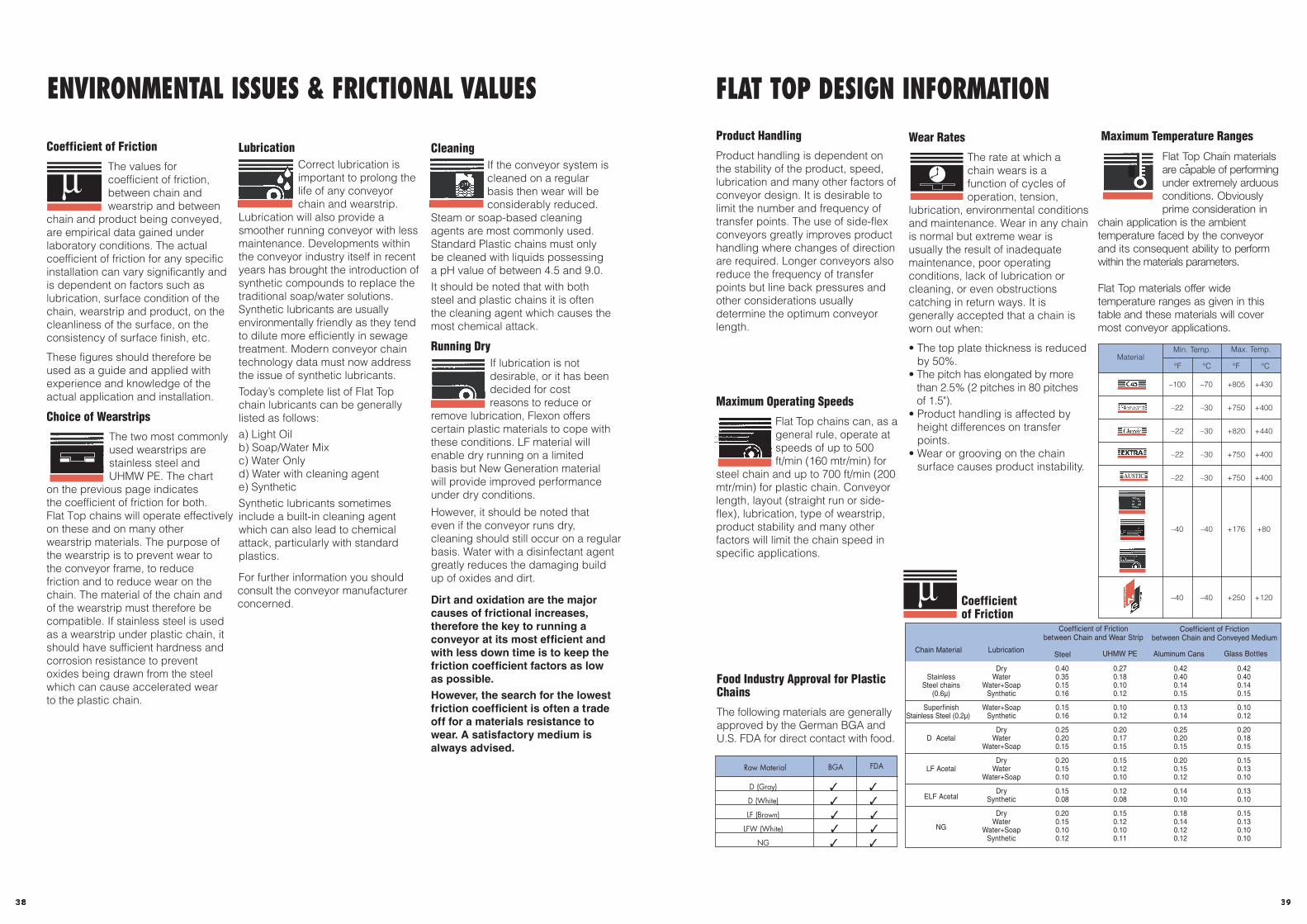
393832
33
ENVIRONMENTAL ISSUES & FRICTIONAL VALUES
Coefficient of Friction
The values forcoefficient of friction,between chain andwearstrip and between
chain and product being conveyed,are empirical data gained underlaboratory conditions. The actualcoefficient of friction for any specificinstallation can vary significantly andis dependent on factors such aslubrication, surface condition of thechain, wearstrip and product, on thecleanliness of the surface, on theconsistency of surface finish, etc.
These figures should therefore beused as a guide and applied withexperience and knowledge of theactual application and installation.
Choice of Wearstrips
The two most commonlyused wearstrips arestainless steel andUHMW PE. The chart
on the previous page indicates the coefficient of friction for both.Flat Top chains will operate effectivelyon these and on many otherwearstrip materials. The purpose ofthe wearstrip is to prevent wear tothe conveyor frame, to reducefriction and to reduce wear on thechain. The material of the chain andof the wearstrip must therefore becompatible. If stainless steel is usedas a wearstrip under plastic chain, itshould have sufficient hardness andcorrosion resistance to preventoxides being drawn from the steelwhich can cause accelerated wearto the plastic chain.
LubricationCorrect lubrication isimportant to prolong thelife of any conveyorchain and wearstrip.
Lubrication will also provide asmoother running conveyor with lessmaintenance. Developments withinthe conveyor industry itself in recentyears has brought the introduction ofsynthetic compounds to replace thetraditional soap/water solutions.Synthetic lubricants are usuallyenvironmentally friendly as they tendto dilute more efficiently in sewagetreatment. Modern conveyor chaintechnology data must now addressthe issue of synthetic lubricants.Today’s complete list of Flat Topchain lubricants can be generallylisted as follows:a) Light Oilb) Soap/Water Mixc) Water Onlyd) Water with cleaning agente) SyntheticSynthetic lubricants sometimesinclude a built-in cleaning agentwhich can also lead to chemicalattack, particularly with standardplastics.
For further information you shouldconsult the conveyor manufacturerconcerned.
CleaningIf the conveyor system iscleaned on a regularbasis then wear will beconsiderably reduced.
Steam or soap-based cleaningagents are most commonly used.Standard Plastic chains must onlybe cleaned with liquids possessinga pH value of between 4.5 and 9.0.It should be noted that with bothsteel and plastic chains it is oftenthe cleaning agent which causes themost chemical attack.
Running DryIf lubrication is notdesirable, or it has beendecided for costreasons to reduce or
remove lubrication, Flexon offerscertain plastic materials to cope withthese conditions. LF material willenable dry running on a limitedbasis but New Generation materialwill provide improved performanceunder dry conditions.
However, it should be noted thateven if the conveyor runs dry, cleaning should still occur on a regularbasis. Water with a disinfectant agentgreatly reduces the damaging buildup of oxides and dirt.
Dirt and oxidation are the majorcauses of frictional increases,therefore the key to running aconveyor at its most efficient andwith less down time is to keep thefriction coefficient factors as lowas possible.However, the search for the lowestfriction coefficient is often a tradeoff for a materials resistance towear. A satisfactory medium isalways advised.
µFlat Top Chain materialsare capable of performingunder extremely arduousconditions. Obviouslyprime consideration in
chain application is the ambienttemperature faced by the conveyorand its consequent ability to performwithin the materials parameters.
Flat Top materials offer widetemperature ranges as given in thistable and these materials will covermost conveyor applications.
