flash llrf system: status and upgrade plans
TRANSCRIPT

FLASH LLRF System: Status and Upgrade Plans
Valeri Ayvazyan, DESY
on behalf of LLRF Team
FLASH Seminar, DESY, November 10, 2009

2
Outline
• LLRF System Status
• Recent Progress
• Operation Experience
• Measured Performance
• Future Plans
• Conclusion

3
LLRF System Architecture
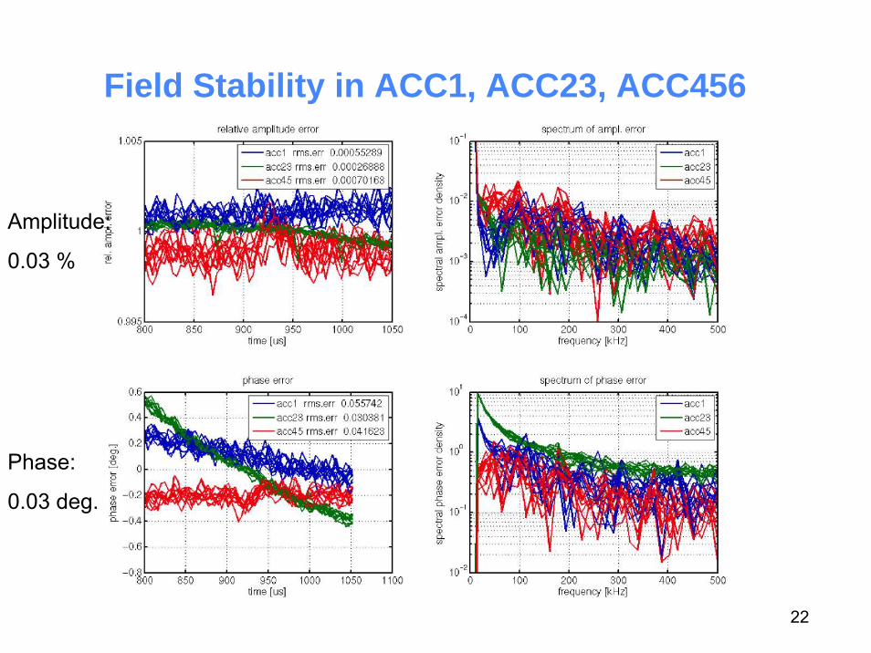
Requirements: up to 0.03% for amplitude and 0.03 deg. for phase

4
LLRF Controllers used During User Run
RF System User operation Development Backup
RF Gun SIMCON 3.1 - DSP
ACC1 SIMCON DSP250 kHz IF
SIMCON x354 MHz
DSP250 kHz
ACC23 DSP250 MHz IF
- Redundant FFDAC8
ACC456 DSP250 MHz
SIMCON x3ATCA
54 MHz
Redundant FFDAC8
DSP (2000), SIMCON (2006), ATCA (2009)
and monitoring signals for all modules (forward/reflected/probe)
5
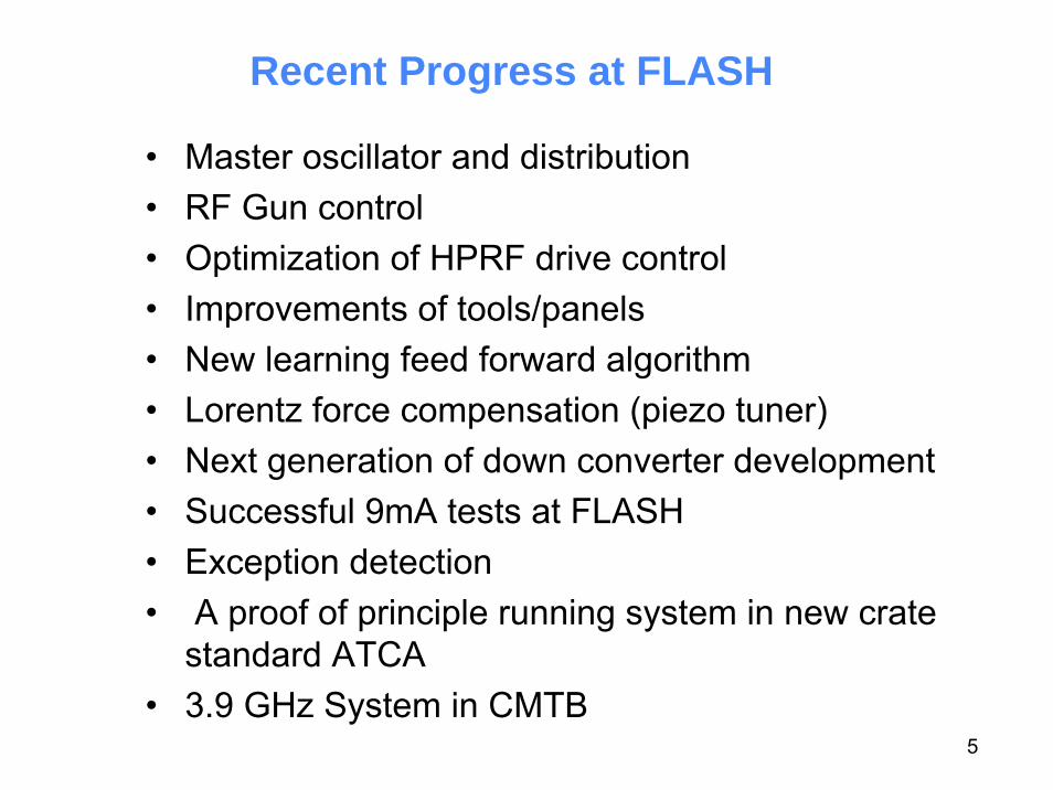
• Master oscillator and distribution• RF Gun control • Optimization of HPRF drive control• Improvements of tools/panels• New learning feed forward algorithm• Lorentz force compensation (piezo tuner) • Next generation of down converter development• Successful 9mA tests at FLASH• Exception detection• A proof of principle running system in new crate
standard ATCA• 3.9 GHz System in CMTB
Recent Progress at FLASH

6
Operation Experience with New MO
Generated and distributed frequencies:
50 Hz, 1 MHz, 9 MHz, 13.5 MHz, 27 MHz, 81 MHz, 108 MHz,1.3 GHz, 1.517 GHz, 2.856 GHz
• RF power levels adequate for all users
• Less complains about phasestability related to the new MO
• Less sensitive against touchingcables
• Extensive diagnostics allows for on-line monitoring of phase drifts and power levels
• No failures (survived power outage)

7
Layout of the Distribution System in FLASH

8
RF Gun Stability
RF Gun field measurement calibration
SASE intensity fluctuations down from 25% to a few percent
Before calibration
After calibration
Utrans = Ufor + Uref
Nov. 5, 2008
Nov. 27, 2008

9
Optimization of HPRF Drive ControlGoal: Efficient use of RF power and reduction of coupler tripsPhase modulation during fillingMinimum reflection at the end of filling time has been reached
Energy gain ~3 %

10
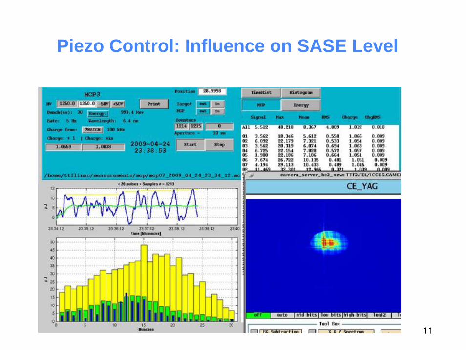
Piezo Control
Time [μs]
Det
unin
g [H
z]flat-top
Permanent piezo control system installation at ACC3, ACC5 and ACC6 with operator interface
11
Piezo Control: Influence on SASE Level

12
Examples for LLRF Exceptions

13
Quench Detection and Handling
• Fast / slow quench detection• BIC interlock interface• DOOCS quench detection middle layer server

14
ATCA-based LLRF System: It Works!
ATCA CPU Blade
ATCA Carrier Board
ADC (AMC board)
Timing Module
Vector Modulator

15
ATCA Set-up in Lab with 4 Carrier Blades

16
List of Operator and LLRF Expert Functions
Operators:Setting VS ampl. and phaseBeam loading compensationFeedback and feedforwardAdaptive feedforwardFeedback gainFill and flat top durationBeam based feedbacks
– Compression (injector)Slow quench detection
Experts:Incident wave and loaded Q adjustmentCalibration of VSEnergy profile along bunch train Cavity slow tuningLorentz force compensationLoop phase adjustmentLoop gain calibrationMeasurement of beam phaseGradient calibrationRF power calibrationBeam based feedbacks
– Bunch arrival (experimental)– Beam energy (experimental)
Real time quench detection

17
Cavity Loaded Q and Phase Adjustment
Motorized three stub waveguide tunersare in use - Different type of tuners at ACC6- Phase range up to 120 deg.- Improvement from ±30° to ±3°

18
Beam-Based Calibration with Moderate Charge
• Preliminary calibration by RF measurement• Good beam requires: requesting 240nC,
usually we got 100 -120nC

19
Energy Based Calibration• Calibration with energy gain measurement by
cavity / module detuning (together B.Faatz)• Different methods are in agreement with ~1%
Courtesy: R.Kammering

20
ILC 9mA Test• Stable operation at 1MHz beam repetition rate was achieved, resulting in stable 3mA
running with a full 800us pulse for over ten contiguous hours.
• Quick start-up after machine access (40 min)
• Several hours of operation at ~9mA but with short trains (300-500us)
• Achieved full pulse length (800us, 2400 bunches) at 6mA for short period

21
Typical Problem in the LLRF System
Phase drifts of the order of few degree per day.– Cables, connectors, MO, downconverter
Reproducibility of cavity fields especially cavity phases with respect to the beam after maintenance period.
Large changes of settings (wave length) require presence of rf expert– Loop phase (if klystron HV is changed)– Feedforward table– Beam loading compensation– Feedback gain– Vector-sum calibration (sometimes)– Cavity tuning– Timing (pulse length)
LLRF expert needs to be available several hours per week to help withdifferent types of problems
Note 1: Often LLRF is blamed for problems in other systemsNote 2: Sometimes LLRF induced downtime is caused by operator error
22
Field Stability in ACC1, ACC23, ACC456
Phase:
0.03 deg.
Amplitude:
0.03 %

23
n Pulse-to-Pulse Beam Stability:Short-term, bunch-to-bunch (800us) :
egd 0.0092 %, 015.0A/A rmsrms == ϕΔΔ
Mid-term, pulse-to-pulse (10min) : egd 0.0147 %, 016.0A/A rmsrms == ϕΔΔ
Long-term, drifts (1hour) : deg 0.05 %, 09.0A/A pkpkpkpk == ϕΔΔ
θA = 2e-3/°C, θP = 0.2°/°C
n Stability lab results (single channel) :
BW=1MHzBW=1MHz
- VME active multi-channel receiver, Readout bandwidth1MHz- LO / IF leakage –72dB, Crosstalk –67...-70dB- SIMCON DSP (14-Bit ADC)
Parameter :
Beam Stability – Performance Tests at FLASH
0.022%(RUN
10/2007)
0.016%(RUN
11/2008)
0.008%(RUN
01/2008)
Desired XFEL value
EUROFEL DS3.9, Delivery Report 01/2008, F.Ludwig et.al.

24
0.02% rms flatness over pulse train 45 μJ for10x10 mm apertures, 100 kHz at 7.02 nm
Energy/SASE Performance
80 bunches, 100kHz, ~3nC
30 bunches, 100kHz, ~1nC

25
Upgrade Plans
RF upgrade in 2009/2010: major modifications– installation the 3rd harmonic (3.9 GHz) accelerating module– installation of the 7th accelerating module → energy up to ~ 1.2 GeV ↔ <5 nm– exchange of the RF gun– upgrades of RF stations and waveguide distribution

26
LLRF Installation after FLASH UpgradeRF System User operation Development Backup
RF Gun SIMCON - DSP
ACC1 SIMCON x1250 kHz IF
ATCA54 MHz
DSP250 kHz
ACC39 SIMCON54 MHz
- LIBERA
ACC23 SIMCON x2250 kHz
- DSP250 kHz
ACC45 SIMCON x2250 kHz
ATCA54 MHz
DSP250 kHz
ACC67 SIMCON x2250 kHz
- ATCA54 MHz
DSP (2000), SIMCON (2006), ATCA (2009)

27
Status of LLRF Installations
GUN, ACC1 ACC23, ACC45, ACC67

28
MO: Upgrade Plan During Shutdown
• Installation of the second Master Oscillator (90% done)
• Installation of new 1.3 GHz power amps (higher output power to
compensate for cabinet cable losses)
• Cleaning up cables in the injector area
- new cabling for ACC1, ACC39 (ACC1, ACC39 dev.) systems(?)
• New subdistribution rack in Hall 3 extension to provide more „tap
points“ for MO signals with diagnostics
• Improve DOOCS data aquisition/logging

29
LLRF Improvement Plans
• Improve long term phase stability (which is of the order of few degrees)
• Fix problems with adaptive feedforward / controller server
– including handling of exceptions, variable beam loading
• RF Gun control (automatic start-up, calibration)• Automated calibration of vector-sum• Reproducibility
– Restoring beam parameters after shutdown or interlock trip• Slow feedback for pulse train stability (RF and beam based)• Implement LLRF control system for XFEL at FLASH
– improve field regulation, operability, availability, reliability• Automation of LLRF operation
• High gradient and high beam loading require advanced applications
• Documentation

30
Conclusion
• RF control performance goals for FLASH achieved- 0.03% for amplitude and 0.03 deg. for phase (short term)- long term phase stability is +/- 1 deg. (concept for reducing long term drifts demonstrated)
• User FEL experiments in different fields have been performed successfully with RF feedback only
• The specific needs for improvement of the LLRF at the FLASH userfacility have been understood
• In the coming years the LLRF at FLASH will be upgraded to the same systems as planned for the European XFEL
• More diagnostics & automation are required • FLASH as a world-wide unique test facility for SCRF technology can
be used parallel to user operation with high efficiency
More Info:http://mskpc14.desy.de/wiki/index.php/Main_Page