flammability limit measurements for dusts in 20-l...
TRANSCRIPT
Flammability limit measurements for dusts in 20-L and 1-m3 vessels
John E. Going a , Kris Chatrathia, Kenneth L. Cashdollar b* Fike Metal Products, P.O. Box 610, 704 South 10th Street, Blue Springs, MO 64015, USA
b Pittsburgh Research Laboratory, National Institute fo r Occupational Safety and Health, Pittsburgh, PA 15236, USA
Abstract
Two types of flammability limits have been measured for various dusts in the Fike 1-m3 (1000-L) chamber and in the Pittsburgh Research Laboratory (PRL) 20-L chamber. The first limit is the minimum explosible concentration (MEC), which was measured at several ignition energies. In addition to the three dusts studied previously (bituminous coal, anthracite coal, and gilsonite), this work continues the effort by adding three additional dusts: RoRo93, lycopodium, and iron powder. These materials were chosen to extend the testing to non-coal materials as well as to a metallic dust. The new MEC data corroborate the previous observations that very strong ignitors can overdrive the ignition in the smaller 20-L chamber. Recommendations are given in regard to appropriate ignition energies to be used in the two chambers. The study also considered the other limiting component, oxygen. Limiting oxygen concentration (LOC) testing was performed in the same 20-L and 1-m3 vessels for gilsonite, bituminous coal, RoRo93, and aluminum dusts. The objective was to establish the protocol for testing at different volumes. A limited investigation was made into overdriving in the 20-L vessel. The LOC results tended to show slightly lower results for the smaller test volume. The results indicated that overdriving could occur and that ignition energies of 2.5 kJ in the 20-L vessel would yield comparable results to those in thè 1- m3 vessel using 10.0 kJ. The studies also illustrate the importance of dust concentration on LOC determinations.
1. Introduction
Many explosibility measurements are needed for safety or hazard analyses. These include the basic explosibility parameters, maximum pressure and rate of pressure rise, as well as explosibility limit parameters such as fuel concentration, oxidant concentration, and ignition energy. The fuel concentration limit, often referred to as Minimum Explosible Concentration, MEC (or lean flammable limit, LFL) is the lowest concentration of dust dispersed in air that can propagate an explosion. Today, most MEC measurements are made in either a 20-L vessel or a 1-m3 (1000-L) vessel. The 20- L vessel is considerably more convenient to use; the 1- m3 vessel is expected to produce data that are more representative of industrial scale explosions. Another limit measurement of use in hazard analysis is the Limiting
Oxygen Concentration (LOC) or Minimum Oxygen Concentration (MOC). The LOC, which is the term used in this paper, is the oxygen concentration at the boundary between propagation and nonpropagation of the dispersed dust cloud. LOC data are used, along with an appropriate safety factor, to establish safe inerting levels in industrial processes.
Since the MEC and LOC values áre experimentally determined in the laboratory, one of the on-going concerns is that of overdriving the system by a large ignition source. This is of particular concern with the smaller 20- L vessel. Dust clouds are inherently more difficult to ignite than gases and therefore stronger ignition sources are used in testing. A “true” limit measurement should be independent of ignition energy. When the ignition source is too weak, both the measured MEC and LOC will be higher than the true value. The system is underdriven and the results are based more on ignitability than flammability. In theory, the ignition energy is increased until the limit measurements are independent of energy. At some point, however, the energy level is excessive

for the size of the vessel and the system is “overdriven”. In this situation, the energy contributed by the ignitor is sufficient to combust enough dust so that the result appears to be an explosion although there is no real propagation beyond the ignitor flame. Similarly, an overly strong ignitor can markedly change the initial test conditions by raising the overall temperature of the system, which in turn would lower the apparent limits and a nonexplosible system would appear to be explosible. A plot of ignition energy versus the measured limit would ideally have a vertical asymptote where the limit is independent of energy. For most dusts, however, this is not the case, particularly in the 20-L vessel.
Comparison measurement between the 20-L and 1-m3 vessels can be used to evaluate the overdriving effect. Overdriving is generally unlikely to occur in the 1-m3 vessel and in principle the 1-m3 vessel can be used to establish the energy independent limit value. Such comparisons of vessel size have been made by Hertzberg, Cashdollar and Zlochower (1988) comparing 20-L vs. 120-L limit data for gases, by Cashdollar and Chatrathi (1992), comparing 20-L vs. 1-m3 MEC data for dusts, and by Bartknecht (1989) and Siwek (1988), comparing 20-L vs. 1-m3 data for dusts. Bartknecht (1989) did not report the effect of different energy sources in the 20-L vessel, but did note that the LOC results from a 10-kJ ignitor in a 20-L vessel were ~ 1.6 times lower than those found in a 1-m3 vessel with the same ignition energy. This difference was attributed to the energy of the ignition source affecting the entire vessel volume and not acting like a point source. Siwek (1988) extended this work by considering the effect of various lower energy ignitors in the 20-L vessel. He noted that the 10 kJ ignitor gave much higher LOCs in the 1-m3 vessel in comparison with those found in the 20-L vessel. Using an ignition energy of 2.5 to 1 kJ in the 20-L vessel brought its LOC into better agreement with the 1-m3 values. Siwek also compared the MEC values for 16 dusts measured with 10 kJ ignition in both 20-L and 1- m3 vessels. The issue of overdriving in a 20-L vessel and its relation to ignition source energy for MEC testing has also been discussed by Chawla, Amyotte and Pegg (1996).
The current testing was performed in a 20-L chamber at the NIOSH Pittsburgh Research Laboratory (PRL),1 located near Pittsburgh, PA and in the 1-m3 vessel located at Fike Corporation in Blue Springs, MO. Both vessels have been used extensively for dust and gas testing. This paper reports on the new comparative MEC tests for RoRo93 (a tetramethylpiperidine derivative used for a round robin test in 1993), lycopodium, and iron powder and comparative LOC tests for gilsonite,
Pmturt transducer
_ ✓To vocuum pump
Scoto'Cm
Fig. 1. Vertical cross-section of Pittsburgh Research Laboratory 20- L chamber.
Pittsburgh coal, RoRo93, and aluminum powder. Limits were determined versus energy levels with the goal of establishing the appropriate 20-L ignition energy that yields data equivalent to 1-m3 data.
2. Experimental
The 20-L dust explosibility data were obtained in the PRL 20-L laboratory chamber (Cashdollar & Hertzberg, 1985) shown in Figs. 1 and 2. The near-spherical chamber is made of stainless steel and has a pressure rating of 21 barg. The hinged top is attached with six19-mm diameter bolts which are not shown. Strain gauge pressure transducers measured the explosion pressure. The data were collected by a high speed personal com-
' The Pittsburgh Research Laboratory was part of the U.S. Bureau of Mines before its transfer to NIOSH in October, 1996.
Fig. 2. Horizontal cross-section of Pittsburgh Research Laboratory 20-L chamber.

puter (PC) based data acquisition system. The dust to be tested can be placed either in the dust reservoir or on top of the dispersion nozzle at the bottom of the chamber (Fig. 1). After the dust and igniter have been placed in the chamber, the top is bolted on and the chamber is partially evacuated to an absolute pressure of 0.14 bara. Then a short blast of dry air (0.3 s duration from a 16- L reservoir at 9 barg) disperses the dust and raises the chamber pressure to about 1 bara. The ignitor is activated after an additional delay of 0.1 s. This results in a total ignition delay of 0.4 s from the start of dispersion until ignition. The experimental dust concentration reported in this paper is the mass of dust divided by the chamber volume, i.e. the nominal dust loading.
The Fike Corporation 1-m3 chamber (Figs. 3 and 4) was also used to measure dust explosibilities. The 1-m3 chamber is spherical with an internal diameter of 1.22 m and a wall thickness of 9.5 mm. It has a pressure rating of 21 barg. The two halves of the sphere are connected by 12 bolts of 51 mm diameter. Two variable reluctance pressure transducers were used to measure the explosion pressure. Data from the instruments were collected by a high speed PC based data acquisition system.
The dust injection system for the 1-m3 chamber consists of a 5-L dispersion reservoir, a 19-mm pneumatically activated ball valve, and a rebound nozzle (Fig. 3). In previous work (Cashdollar & Chatrathi, 1992), a ring nozzle was used. To create a dust cloud, a weighed sample of dust is placed in the dispersion reservoir. The reservoir is pressurized with dry air to 20 bara and the chamber is partially evacuated to 0.88 bara. Activation
of the ball valve disperses the dust and air into the 1- m3 chamber through the rebound nozzle and raises the chamber pressure to about 1 bara. The ignitor is fired 0.6 s after activation of the ball valve. The reported experimental dust concentration for the 1-m3 chamber is the mass of dust divided by the vessel volume.
The dispersion time and measured Kst values (and presumably the turbulence level) in the Fike 1-m3 chamber are comparable to those in European 1-m3 chambers (Bartknecht, 1989). This is the turbulence level in VDI Standard 3673, ISO Standard 6184/1, and ASTM Standard E l226 used to determine the maximum rate of pressure rise of a dust explosion. The Kst and turbulence levels in the PRL 20-L chamber are lower, but this should not significantly affect measurements of the MEC or LOC (Cashdollar & Chatrathi, 1992). The main effect of increased turbulence at low dust concentrations is to make the dust cloud more difficult to ignite (Amyotte, Chippett & Pegg, 1989). However, with the strong igniters used for the tests, the somewhat higher turbulence level in the 1-m3 chamber should have little effect on the measurements.
The ignition sources used for the tests were electrically activated chemical ignitors manufactured by Fr. Sobbe of Germany. The ignitors are composed of 40% zirconium, 30% barium nitrate, and 30% barium peroxide. They are activated electrically with an internal fuse wire and deliver their energy in about 10 ms. The Sobbe ignitors are available in energies of 0.25, 0.50, 1.0, 2.5, 5.0 and 10.0 kJ. These are nominal calorimetric energies based on the mass of pyrotechnic powder in
Fig. 3. Vertical cross-section of Fike 1-m3 vessel.
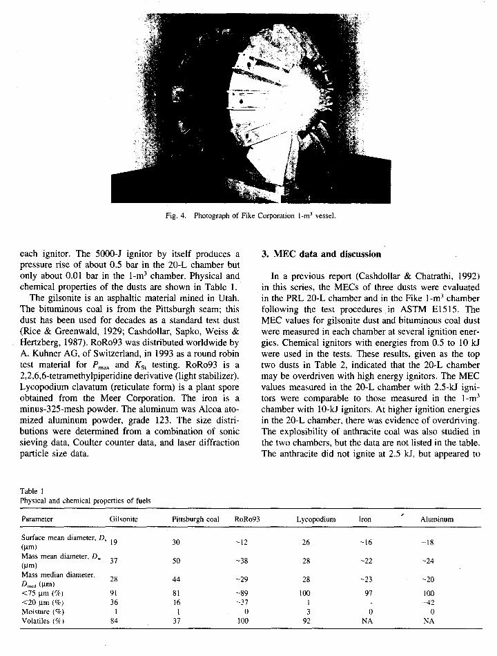
Fig. 4. Photograph of Fike Corporation 1-m3 vessel.
each ignitor. The 5000-J ignitor by itself produces a pressure rise of about 0.5 bar in the 20-L cham ber but only about 0.01 bar in the 1-m3 chamber. Physical and chemical properties of the dusts are shown in Table 1.
The gilsonite is an asphaltic material mined in Utah. The bituminous coal is from the Pittsburgh seam; this dust has been used for decades as a standard test dust (Rice & Greenwald, 1929; Cashdollar, Sapko, W eiss & Hertzberg, 1987). RoRo93 was distributed worldwide by A. Kuhner AG, of Switzerland, in 1993 as a round robin test material for P max and KSl testing. RoRo93 is a 2,2,6,6-tetramethylpiperidine derivative (light stabilizer). Lycopodium clavatum (reticulate form) is a plant spore obtained from the M eer Corporation. The iron is a minus-325-mesh powder. The aluminum was Alcoa atomized aluminum powder, grade 123. The size distributions were determ ined from a combination of sonic sieving data, Coulter counter data, and laser diffraction particle size data.
3. MEC data and discussion
In a previous report (Cashdollar & Chatrathi, 1992) in this series, the MECs of three dusts were evaluated in the PRL 20-L cham ber and in the Fike 1-m3 cham ber following the test procedures in ASTM E l515. The MEC values for gilsonite dust and bituminous coal dust were measured in each cham ber at several ignition energies. Chemical ignitors with energies from 0.5 to 10 kJ were used in the tests. These results, given as the top two dusts in Table 2, indicated that the 20-L cham ber may be overdriven with high energy ignitors. The MEC values m easured in the 20-L chamber with 2.5-kJ ignitors were comparable to those measured in the 1-m3 chamber with 10-kJ ignitors. At higher ignition energies in the 20-L chamber, there was evidence of overdriving. The explosibility of anthracite coal was also studied in the two chambers, but the data are not listed in the table. The anthracite did not ignite at 2.5 kJ, but appeared to
Table 1Physical and chemical properties of fuels
Parameter Gilsonite Pittsburgh coal RoRo93 Lycopodium Iron Aluminum
Surface mean diameter, Ds (Jim) 19 30 -12 26 -16 -18
Mass mean diameter. Dw (|xm) 37 50 -38 28 -22 -24
Mass median diameter, £>mcd (Hm)
28 44 -29 28 -23 -20
<75 |i.m (%) 91 81 -89 100 97 100<20 |im (%) 36 16 -37 1 - -42Moisture (%) 1 1 0 3 0 0Volatiles (%) 84 37 100 92 NA NA

Table 2Summary of MEC testing results (g/m3)
Dust 20-L vessel 1 m3 vessel
1 kJ 2.5 kJ 5 kJ 10 kJ 2.5 kJ 5 kJ 10 kJ
Gilsonite 50±5 35±5 30±5 30±4 39±3 41±3 36±3Pittsburgh coal 90±5 80±10 60±10 50±10 90±5 85±5 80±5RoRo93 - 36±3 28±4 25±5 34±4 35±4 35±4Lycopodium - 45±4 30±5 - 41±2 42±2 42±2Iron - 250±30 ~200±40 - 210±10 195±5 195±5
ignite at 5 kJ in the 20-L chamber. It did not ignite even at 30 kJ in the larger 1-m3 chamber.
The previous study (Cashdollar & Chatrathi, 1992) has now been extended to two additional carbon-based dusts as well as to a metallic dust with the goal of evaluating the extent of the overdriving phenomenon more thoroughly. The organic dusts were selected to be noncoal in order to widen the study. RoRo93 was selected as it has been widely studied in recent years; lycopodium was chosen due to its universal acceptance as an explos- ibility standard (because of its uniform size). Explos- ibility tests using RoRo93 were done with 2.5, 5, and 10-kJ ignitors in both chambers. The results are shown in Figs. 5 and 6.
A — 2.5 kJ
AA
........... t \ y T ...........,t
L\ y A
c y
a s .......• _0 20 40 60 80 100 120 140
c
35
c>S'a.■o
80
60
40
20
0
V ----- - 10 kJ
7 s '
/ 7/ 'i
..- d .-------- s e ---------
7
0 10 70 80
Fig. 5. MEC data for RoRo93 from the 20-L chamber.
20 30 40 50 60
Concentration, g/m3
Fig. 6. MEC data for RoRo93 from the 1-m3 chamber.
In these and subsequent figures only the data points and curves for one or two ignitors will be shown for purposes of clarity. The top portion of each graph shows the maximum absolute explosion pressure plotted against dust concentration. The effect of the ignitor is partially corrected by subtracting the pressure rise Sue to the ignitor itself from the maximum explosion pressure. The lower portion shows the maximum rate of pressure rise, normalized by the cube root of the chamber volume, (dP/dt)Vin. When tested at the standard turbulence level of ASTM E l226, this is known as the KSt value. The value (dP/dt)Vui is proportional to the maximum flame speed (Amyotte et al., 1989; Hertz- berg & Cashdollar, 1987; Hertzberg, Cashdollar & Zlo-

chower, 1988). The primary criterion for flame propagation in the 20-L tests was a 1 bar pressure rise, corrected for the pressure rise of the ignitor itself. However, an additional criterion of a pressure rate of rise of1.5 bar-m/s was also used in evaluating the 20-L results (Cashdollar & Chatrathi, 1992). Using these criteria, the MEC for RoRo93 with a 2.5-kJ ignitor in the 20-L chamber was found to be 36 g/m3. The results shown in Table 2 show the change in MEGs at higher ignition energies. The criterion for flame propagation in the 1- m3 chamber is 1 bar pressure rise or an absolute pressure of 2 bara. Based on this criterion, the MEC for RoRo93 is 35 g/m3 with a 10-kJ ignition source in the 1-m3 vessel. There was no significant pressure rise at lower concentrations while the pressure continued to rise at higher concentrations. The experimental MEC values, given in Table 2, show little dependency on ignition energy in the 1-m3 chamber.
Lycopodium testing was performed at 2.5 and 5 kJ in the 20-L vessel and at 2.5, 5, and 10 kJ in the 1-m3 vessel. The results are shown in Figs. 7 and 8 for one ignition energy and the summary data are given in Table 2. The ~41 g/m3 MEC for the 1-m3 vessel was clearly independent of ignition energy. The 20-L vessel showed \ an energy dependency and gave an MEC of 45 g/m3 at2.5 kJ and 30 g/m3 at 5 kJ.
25
20
1 Ҥ , 10
0
A --- 25 kJ
A
y i<3....................
Js<3
20 10040 60 80
Concentration, g/m3
Fig. 7. MEC data for lycopodium from the 20-L chamber.
120
£
>
%
Concentration, g/m3
Fig. 8. MEC data for lycopodium from the 1-m3 chamber.
For the RoRo93 and lycopodium, as well as for gil- sonite and bituminous coal, the 2.5-kJ MEC data in the 20-L chamber agreed better with the 10-kJ data in the 1-m3 chamber. At higher ignition energies, there was no evidence of overdriving in the 20-L chamber.
The iron results are shown in Figs. 9 and 10 and are listed in Table 2. The MEC was ~195 g/m3 at 10 kJ in the 1-m3 vessel. In the 20-L chamber, the MEC was ~200 g/m3 at 5 kJ and 250 g/m3 at 2.5 kJ. In this case, the 5-kJ ignitor data in the 20-L chamber agreed better with the 1-m3 data using the 10-kJ ignitor.
The effect of ignition energy on MEC measurement in the 20-L and 1-m3 chambers was studied in a previous report (Cashdollar & Chatrathi, 1992). The results of those tests along with the current results for RoRo93, lycopodium, and iron powder are summarized in Table2 and Fig. 11, where the measured or apparent MEC is plotted versus ignition energy. The pattern observed previously for gilsonite and Pittsburgh coal in the 1-m3 was again seen with the three new dusts. That is, the asymptotes are nearly vertical and the measured MECs from the 1-m3 vessel are essentially independent of ignition energy over the range studied. The 20-L tests did not, however, show the same independence of ignition energy. As the energy increased from 2.5 kJ, the apparent MEC decreased and was definitely less than the

Concentration, g/m3
Fig. 9. MEC data for iron powder from the 20-L chamber.
1-m3 results for the carbonaceous dusts. This is a result of overdriving the smaller vessel with too strong an ignition source. For the carbonaceous dusts, the closest agreement to the 1-m3 data was found with a 2.5-kJ igni- tor in the 20-L vessel.
The iron results appear to be somewhat different in that the 20-L MEC at 2.5-kJ ignition energy was higher than the 1-m3 MEC. It must be noted that these MEC values are three to five times higher than those found with the carbon-based fuels. The data in Fig. 1 ID show that for the more difficult-to-ignite dusts (such as this iron powder) with higher MEC values, the use of a 5- kJ ignitor in the 20-L chamber may be more appropriate for agreement with the 1-m3 data at 10 kJ.
Siwek (1988) compared the MEC values measured with a 10-kJ ignitor in 20-L and 1-m3 vessels. He concluded that there was no significant effect of vessel volume on the measured MECs, i.e. that the MECs from the two vessels agreed to within one concentration increment. However, in his MEC tests, the dust concentration increment was 10 g/m3. A close examination of the data in Fig. 8 of his paper, however, suggests that the MECs for six of the 16 dusts studied were between10 and 30% lower in the 20-L vessel than in the 1-m3 vessel. Two of the dusts were less than 10% higher and the rest were about the same. This suggests that some
7
6
§ 4
® 3
2
’ 0 50 100 150 200 250 300 350 400
20
15
c>§ 10
%
5
00 50 100 150 200 250 300 350 400
Concentration, g/m3
Fig. 10. MEC data for iron powder from the 1-m3 chamber.
overdriving was occurring, at least for some of the dusts. Another difference between Siwek’s data and the data presented in this paper is that he reports the MEC as the highest concentration that does not produce an explosion rather than as the lowest concentration that just produces an explosion.
In conclusion, the MEC data presented in this paper show that overdriving can occur in the 20-L vessel using 5-kJ or 10-kJ ignitors. For the dusts tested, the MEC data using 2.5-kJ or 5-kJ ignitors in the 20-L vessel agreed best with the MEC data from the 1-m3 vessel using a 10-kJ ignitor. The extent of overdriving in the 20-L vessel is dependent on the type of dust. There was less of an effect (Fig. 11) for the RoRo93, gilsonite, and lycopodium, all of which have a high volatility. The overdriving in the 20-L vessel was greatest for the coal dust, which had a much lower volatility.
4. LOC data and discussion
All of the LOC testing in the 1-m3 vessel was conducted with the 10-kJ ignition source and the 20-L tests were conducted mainly with 2.5- or 5-kJ ignition sources. The criteria for ignition were unchanged from the MEC testing. LOC testing also incorporated the effect of fuel con
v — 10 kJ
\
7..... . t ...... t ;..........

Fig. 11. Effect of ignition energy on apparent MEC.
centration on the measurement. In effect, the fuel concentration was varied in order to determine the lowest possible LOC at any concentration, i.e. the “worst” case. The oxygen concentration was reduced by adding nitrogen to the air. This was done in both test vessels as well as in the dust injection gas reservoirs for the 20-L and 1-m3 chambers. This approach eliminated any question about the actual 0 2 concentration in the initial stages of dispersion and ignition.
The LOC data for die RoRo93 dust are shown in Fig. 12. Tests were made over a range of dust concentrations • in order to determine the LOC at the “worst” case. The ignitions/explosions are shown as the solid data symbols and the nonignitions/nonexplosions are shown as the open data symbols. The 1-m3 chamber data using 10-kJ ignitors are shown in the top part of the figure and the20-L data using 2.5-kJ ignitors are shown in the bottom of the figure. In the 1-m3 chamber, the RoRo93 dust ignited and burned at 11% oxygen but not at 10% oxygen. The reported LOC value is then taken as the average of these values or 10.5%. In the 20-L chamber, the
RoRo93 also ignited at 11% but not at 10% oxygen, so the LOC value is also 10.5%. In this case the LOC value determined in the 20-L chamber using a 2.5-J ignitor was in agreement with the data from the 1-m3 chamber using 10-kJ ignitor. All of the LOC data are summarized in Table 3.
The 20-L data for Pittsburgh coal in Fig. 13 clearly show that the effect of the ignition source is significant in this volume. As ignition energy increases, lower quantities of fuel and oxygen are required to create 1 bar overpressures. A comparison of the 14% oxygen and 150 7 g/m3 coal coordinates on the three 20-L graphs provides a good example of the effect of ignition source. With a 1-kJ ignition source, the 14% oxygen and 150 g/m3 point is outside the flammability envelope. With a 2.5-kJ ignition source, this point is just inside the flammable envelope and with a 5-kJ ignition source, this point is well within the flammability envelope. Increasing the ignition energy increases the size of the flammability zone. As listed in Table 3, the LOC in the 20-L chamber decreased from 13.5% at 1 kJ to 11% at 2.5 kJ and 9.5% at 5 kJ. In the 1-m3 chamber, the LOC is 13.5% at 10 kJ.

14
13
N0 12 l i1 11
10
90 50 100 150 200 250 300 350
14
13
O 12 €
10
90 50 100 150 200 250 300 350
Concentration, g/m3
Fig. 12. LOC data for RoRo93.
Table 3Results of LOC testing (% 0 2)
Dust 20-L vessel i-m3 vessel
1 kJ 2.5 kJ 5 kJ 10 kJ
RoRo93 _ 10.5 8.5 10.5Pittsburgh coal 13.5 11 9.5 13.5Gilsonite - 10.5 8.5 11.5Aluminum - 9.5 8.5 9.5
The results of the gilsonite tests are shown in Fig. 14 and illustrate the effect of concentration on the LOC. For example, the 20-L data show an ignition at 11% 0 2 at 100 and 20Q g/m3 but failure to ignite and bum at 300 g/m3. The dust did not ignite at 10% 0 2 at any concentration tested. The data show that the LOC in the 20-L chamber with a 2.5-kJ ignitor was 10.5% compared to 11.5% measured in the 1-m3 with a 10-kJ ignitor.
As shown in Fig. 15, the LOCs for the aluminum dust were found at much higher dust concentrations than for the carbonaceous dusts. This shows the importance of LOC testing over a wide range of dust concentrations. The measured LOCs for this aluminum were 9.5% using a 10-kJ ignitor in the 1-m3 and 9.5% at 2.5-kJ and 8.5% at 5-kJ in the 20-L chamber. In both cases, the lowest
20-Liter, 2.1 Bum O No-Bum
5 kJ
1-m3,10 k0 Bum O No-Bum
J
........ w ............. : ............ ............ w .............
16
O" 14
1 12 ¿5 ^ 10
Q50 150 250 350 450 550 650
16
O " 1 4
1 12 ì> 10
850 150 250 350 450 550 650
16
cT 14 12
10
g50 150 250 350 450 550 • 650
16
o " 1 4
I 12 “ • 10
850 150 250 350 450 550 650
Concentration, g/m3
Fig. 13. LOC data for Pittsburgh coal.
LOC value was found at a very high dust concentration of ~ 1000 g/m3.
Comparing the LOCs of aluminum and RoRo93 measured in the 20-L chamber with the LOCs measured in the 1-m3 chamber leads to the conclusion that 2.5 kJ is an appropriate ignition source for the 20-L chamber. The 2.5-kJ ignition source appears to neither overdrive nor underdrive the aluminum and RoRo93 systems. However, comparing the gilsonite and Pittsburgh coal LOCs leads to the conclusion that 2.5 kJ does overdrive these dusts in the 20-L chamber. The 1-m3 LOCs for gilsonite and Pittsburgh Coal are 11.5% and 13.5%, respectively, compared with the 20-L LOCs of 10.5% and 11% at 2.5 kJ. -7
All of the LOC data reported here support the conclusion reached by Siwek (1988), i.e. that the 10-kJ ignition source is inappropriate for LOC measurement in the 20-L vessel. Furthermore, the data also indicate that the 5-kJ ignition source is inappropriate for LOC measurement in the 20-L chamber, for the dusts studied. Both the 10-kJ and the 5-kJ sources will overdrive the explosion in the 20-L vessel for most dusts. The results reported here (Table 3) and in Siwek’s paper (figure 20 in Siwek, 1988) indicate that the 1-kJ or 2.5-kJ ignition
D 20-Liter5 kJ
0 • • • •..............................• ■ • • ■ • ■ ■ • ...................... 0 ........
0 0 0 0 0
20-Liter 2.5 kJ
* * i1 >
0 0 1 ? 8 § 0
c
20-Liter 1 kJ
0 O O 0
B

13
NO 12
14
10
90 50 100 150 200 250 300 350
14
13
p*0 12 B
1 11
10
9 0 50 100 150 200 250 300 350
Concentration, g/m3
Fig. 14. LOC data for gilsonite.
source may be the most appropriate ignition source to use for LOC measurement in the 20-L vessel to match the LOC data from the 1-m3 vessel using a 10-kJ ignitor. However, there may be some dusts for which overly conservative LOC values will be obtained in the 20-L chamber with the 2.5-kJ ignitor.
Siwek (1988) recommended that a 5-kJ ignitionsource should be used for dusts with LOC values below 10%. However, neither the current study nor Siwek’s work investigated dusts with LOC values significantly below 10%. This is an area of LOC measurement that needs further study. If it is-assumed that dusts with LOC values below 10% are highly reactive and the effect of the ignition source is to either overdrive or underdrive these systems, then it might be expected that a 5-kJ ignition source would more likely overdrive these systems. Additional data need to be gathered for dusts with LOC values below 10% to establish a clear recommendation.
To obtain unambiguous and practically usable LOC values, the 1-m3 chamber is preferred, especially when LOC values are below 10%. The 20-L LOC values may be somewhat more uncertain, but the 2.5-kJ data from the 20-L vessel appear to be conservative, at least for LOC values above 10%.
In applying the LOC data, one should use a reasonable
20-Liter, 2.S kJ | Bum Q No-Bum •
■Eh
1-m1, 10 kJ0 Bum
O No-Bum •
13
12<N
0 11
£ i o
9
80 500 1000 1500 2000 2500
13
12
o " h
1 aI 10
9
g
0 500 1000 1500 2000 2500
Concentration, g/m3
Fig. 15. LOC data for aluminum.
safety margin. NFPA 69 recommends keeping the oxygen concentration at least 2% below the measured LOC value when protecting equipment. It is important to remember to t the LOC values listed in Table 3 are only for the specific dusts tested and may not be applicable to other particle sizes of the same materials. Often, finer sizes of dusts have lower LOC values. It is also important to recognize that these LOC data are for nitrogen inerting of air. Inerting with other gases such as carbon dioxide may give different results.
5. Conclusion
The data from this study and the previous work (Cashdollar & Chatrathi, 1992) demonstrate that overdriving can occur when using strong chemical ignitors in the 20-L chamber. The result is that apparent MEC values are found which are lower than the “true” values. For most dusts tested, the best agreement is found between 20-L chamber data with 2.5-kJ ignitors and 1- m3 data with 10-kJ ignitors. Overdriving is not a concern when testing with 10 kJ in the 1-m3 vessel. The advantage of the 20-L chamber is that the explosion tests can be conducted more quickly and with much smaller dust samples. In practice, therefore, the 2.5-kJ ignitor is rec-
20-Liter, 2.5 Id ; B Bum
D No-Bum
■
.............. u r a
........
m .......... ■ .......... ■ .......................... w -
ommended for initial testing in the 20-L vessel. For hard-to-ignite dusts with higher MEC values, a 5-kJ ignitor may be more appropriate. If there are significant differences in the MEC values obtained at 2.5-kJ and 5-kJ energies, it may be advisable to go to the 1-m3 vessel for a final MEC determination. If toe dust does not ignite with a 2.5-kJ ignitor, but does ignite with a 5-kJ or 10- kJ ignitor in a 20-L vessel, it is necessary to use a 1-m3 vessel with a 10-kJ ignitor for the final determination.
Similar conclusions can be drawn regarding overdriving the 20-L vessel when making LOC measurements. These and previous data indicate that both 5- and 10-kJ energies are too strong for the 20-L chamber. From the studies carried out to date, the 2.5-kJ ignitor is the most appropriate energy level for 20-L LOC testing, and in fact, the 2.5-kJ data may be slightly conservative for some dusts. Additional LOC studies are needed, particularly for dusts with LOC values below 10%.
Acknowledgements
The authors wish to acknowledge the assistance of G.M. Green and PRL in the collection of the 20-L data and Frankie Terry, Thomas Klug, and Jack Creager of Fike in the collection of the 1-m3 data.
References
Amyotte, P. R., Chippett, S., & Pegg, M. J. (1989). Effect of turbulence on dust explosions. Progress in Energy and Combustion Science,14, 293-310.
Bartknecht, W. (1989). Dust explosions: course, prevention, protection. New York: Springer.
Cashdollar, K. L., & Chatrathi, K. (1992). Minimum explosible dust concentrations measured in 20-L and 1-m3 chambers. Combustion Science and Technology, 87, 157.
Cashdollar, K. L., & Hertzberg, M. (1985). 20-Liter explosibility test chamber for dusts and gases. Review o f Scientific Instruments, 56, 596-602.
Cashdollar, K. L., Sapko, M. J., Weiss, E. S., & Hertzberg, M. (1987). Laboratory and mine dust explosion research at the Bureau of Mines. In Industrial dust explosion, STP 958. Philadelphia, PA: ASTM pp. 107-123.
Chawla, N., Amyotte, P. R., & Pegg, N. J. (1996). A comparison of experimental methods to determine the minimum explosible concentration of dusts. Fuel, 75, 654—658.
Hertzberg, M., & Cashdollar, K. L. (1987). Introduction to dust explosions. In Industrial dust explosions, STP 958. Philadelphia, PA: ASTM pp. 5-32.
Hertzberg, M„ Cashdollar, K. L„ & Zlochower, I. A. (1988). Flamm- ability limit measurement for dust and gases. In 21st Symposium (International) on Combustion (pp. 303-313). Pittsburgh, PA: The Combustion Institute.
Rice, G. S., & Greenwald, H. P. (1929). Coal dust explosibility factors indicated by experimental mine investigations 1911 to 1929. Bureau of Mines Technical Paper 464.
Siwek, R. (1988). Reliability determination of the safety characteristics in 20-L apparatus. Flammable dust explosion. St. Louis, MO.