fl copy - nasa · fl copy tq rewrrw to ... an elastic system consisting of a single mass or of sev...
TRANSCRIPT

FIL EN0. 2-W
TECHNICAL MEMORANDUMIS
FATIONAL .ADVISORY COMMITTEE FOR AERONAUTICS
iVTo. 1051
THE COUPLING OF FLEXURAL PROPELLER VIBRATIONS WITH
THE TORSIONAL CRANKSHAFT VIBRATIONS
By J. Irieyer
Jah.rbuch 1938 der deutschen Luftfahrtforschung
Fl COPYTQ rewrrw to
Ole fftea of the National
Advisory &#Tirrr qeefor Aercw)mutins
wa23f11llwb^n, D, Q
WashingtonDocomber 1943
https://ntrs.nasa.gov/search.jsp?R=20050019482 2018-06-25T12:44:48+00:00Z
I
-- ~illllllllll~li31176014415104
3–-~- ‘——-
NATy ON&L A~VI SORY .COMMITTEE,
—
i.!. .. . ...-——. “. .,:.
‘TECHNICAL MEM ORANIHJM NO, 1051. .,.,, K., .-—-—.
... ----
THE cOUpLI NG OF Il%ExURAL PR OpELLER V13RATI oNs WITH.,.. !.’ ,“THE TORSIONAL CRANKSHAFT VIBRATIONS*
By. J. Meyer - .
The exact mathematical treatment of the problem ispossible by replacing” the propeller. blade by a homogcme–ous prismatic rod. Conclusions can then be drawn as tothe behavior of an actual propel ler., since tests on pro–peller blades have indicated a qualitative agreementwith the homogeneous rod, The natural frequencies aredetermines and the stressing of the systems under thevarious vibration modes are discussed...
>,. .; . ..SUMMARY , ‘ ,-
.-
For. the homogeneous prismatic; rod assumed equivalentto the propelle~ blade, the matliematical so’lution for thecoupling of.the f-1exura.1with the torsional. vibrations ofan elastic system consisting of a single mass or of sev–eral masses is”presented, and valid conclusions ar’e de–rived for the propeller.” Extensive t,ests .confirrned thetheoretical results, -;;.
The most. important conclusion derived was that thecoincidence of a harinonia”.with ..thetorsional vibration,since it give-s,two close–lying natural frequencies ofthe crankshaft–propelzer Qystem is unfavorable, ,the crank–shaft and hub, the propeller blade root, and also the “blade itself. at the tip being tho’feby stressed to a“dan–gerous degree. By spreading Apart the two frequenci-es,as can be done by a change in the elasticity of the tor—sion”ally vibrating’ component system, the harmonics inquestion can be rendered har”mless because their positionis”little affected ly .a change in the magnitudes of thetorsionally vibrating system, ‘The torsional vibration of..-, “.,. ..- .—. . .!-’-----_-__--__--_,.--.-+________________________________‘,
*tll?ieX.opplqng’ d~r Ln”ftschrau’ben-Biegeschwi,ngun&pn mitden Kurbelwell,e&Drehschwingungen. ‘1 Jahrbuch 1938 debdeutsohen Luftfahrtforschung, pp. II T41-J59. .

——-. — ... . ... -.
2 <’.” NACA- Techni&il:’ lfefio;afiduhNo. ‘-1051 “
the system caniot , how_6ier”,-be el”i-minated by similarcombinations. This can-be done only ,%y *employing adamper or an elastic bul (refer enc~i:l~). The maximumvi%rktion’rnomeiit in-the blade root - I&rrimg a few excep–tions – always acts in the direction of the chord.
OBJECT OF THE INVESTIGATION
In recent” years the question as to the catise andprevention of propeller failure in flight has become ofgreatest importance. The failures are all found to becaused 3Y fatigue stresses due to the flexural vibrationsof the propeller blade. A torsiogram of an As–8 enginewas of particular interest (fig. 1). The curve shows,instead cf a single maximur,~, two maximums of the sixthorder. This phenomenon indicates vibrations of the pro-peller %lade because new degrees of freedom can be addedto those of the crankshaft only through the presence ofan elastic propeller llade. It may be remarked in pass–ing that in a fef,~cases vibration of the propeller couldbe established by the naked eye alone. In order to beable to measure experimentally the propeller vibrationsoccurring in flight, the DVL, since 1934, has been em–ploying the’ test apparatus shown in figure 2 (reference17). The setup reproduces the vibrations of the actualradial engine—propeller system, A shaft supported ont~o bearings and the torsional, elasticity of which is
,
of the order of magnitude corresponding to that of mostcrankshafts carries at one end the propeller with hub tobe investigated and at the other end a rotating mass onwhich .tmo unbalanced .weights, displaced in the same senseky. 18?0 excite th9 torsioi.al b.armonics, corresponding to
- the- ~u’re vilration torque of the engine. The mass’ moment-.of iner.t’ia’likewise corresponds approximately to that ofa large radial “engine. with the most usual types of pro–pellers, for rotations of the unbalanced weight up to10,0’00 rpm, there were always obtatned three frequenciesat which the entire, system strongly vilrated (table 1).That appears striking in table 1 is that the frequenciesof the center column are practically constant while thoseof the other two are not, and hence dependto a’ largeextent on the given propeller type. The form of the vi–bration of the second and third frequencies was in mostof the cases very similar, although fo’r ttie second fre-quency the rotating mass - with few exceptions – under-ment considerably larger deflections. The notation

NA GA
nl , na, and nD
-!- course of these
Techrf~cal Memorandum lTo. 1051 3
of the columns w-ill be explained. In the
investigations the question arose to whatextent the flexural propeller vibrations measured on thissetup wer,e’independent of the couyled. torsionally vibrat-ing system.
In the prese’nt paper, starting from the differentialequation setup’ for the elastic propeller, the relationsholding for the coupling of the flexural, propeller vibra-tions with the torsional crankshaft” vibrations are derived.*An explanation is t,hereby provided for.the above:mentionedphenomena. The natural frequencies of the crankshaft-propeller sjstem cannot, however, be numerical].y determinedin th”is manner. An improved test setup is proposed thatcan also be used for in-line engines. It is shown, further-more, that coincidence of the natural frequencies of bothcomponent systems, ‘crankshaft and propeller, is particu-larly dangerous and that the natural frequencies of theentire system and’the deflections for equal exciting torquein general de-oend on the propeller pitch angle.
,.-
SETUP OF Th~ DIFI?ZRENTI.AL EQUATION NOR FREE VIBRATION
There is first considered the ecluivalent system ofa radial engine with propeller assuned rigid (fig. 3) .
(1)
with the solution9D + eL
U2=C ——.—. -—GD 6L
or—————---.__.—————_———___——-———---- ——-—-- —-—————————-——_—____ —
*At ~]:e coflclllsi,o~of the above investigation there was
brou~hi to the attention of the author a paper which like–wise takes up the saw-e problem. (See reference 19 .)
— -. ——..—. . —. —

4 NACA Technical Me~loi-+~,du~,~0. 1051,- ,. <.
,,
‘Actually, however, on account of the elasticity of thepropeller blades th’e crankshaft will not be coupled to arigid mass but to a vibrating structure with infinitedegrees of freedom. The propeller is therefore replacedhy an elastic rod which is fixed to a hub, 61v [fig. 4).
Equilibrium is possi-ole only if the rod, vibratingat position x = t, produces ‘a moment the component ofwhich in the plane at right angles to the shaft ’axis isexactly equal to that acting on the mass eN. A rod can
vibrate in two mutually perpendicular directions, corre-sponding to the twQ principal axes of inertia ,of its -cross section. In the general case if the rod is s~t. ob—lig.ue to the torsional vi’oration plane, vibrations aboutthe two princii~ai axes will ke excited. If Y(x) denGtesthe deflection, th~ inf);hent produced about the longer axis(the chord) is EJ{t)~ (2) and that a’o~ut the shorter
axis 3J~:, J$j. Both moments possess a component in
the torsional vibration plane. If .a denotes the anglewllic”hthe shorter principal axis of the section makeswith the pl,ane of rotation, tlie differential equation ofthe ~ystem from vhich the natural frequencies are computedwhen there are S, rods is
(2)
with the boundary conditions
.

I “-— - ‘- ‘-
NACA Technical Memorandum No. 105’1 5
1. yffl (o) = o 3, y@ = q(1) N
cos a; yth = cfN sin a(1)m.- ...-m.....-d.. . ... ..-.*
2. y“ (o) = o = rcf4“ % N
= rcp‘Os ‘; ‘~1) N
sin ~
and p(x) and J(x) may %e written w(z)Q(x) andJ(@x). The function y(x, t) , according to Bernoulli,
may be written y(x, t) = y(x) sin wt. The partial differ–ent ial equation then goes over into the ordinary linearequation
and setting
the system of equations becomes
II
[
,,h~?x) ‘(x)1 h
o- i4 Q(x) Y(x) =
(4)
% The solution of the prGblem depends on the so,lution’,of thelast two differential equations (~). The variation of thefunctions J(x) and W(X) over the propeller length issuch, tiowever , that great difficulty is encountered in oh- ,taining the complete, solution in exact form. The propellerblades are therefore replaced by homogeneous rods of

6
6 NACA Technical Memorandum No; 1051”
‘rectafig@a’r section. For this case the so-l”ution can beexactly obtained, and provides information as to the rela– .tions for the actua,l propeller.
SOLUTION IOR THE HOMOGENEOUS ROD
Tor the prismatic homo~eneous roil with P = Q = 1the two differential equations (3,) siW?~ifY to
IV fl -_ # fl. “o
‘(x) y(x) =
IVh_i Qh
‘(x)Y(x) = o
}
(5)
Taking account of the boundary conditions 1 and 2, thereare obtained for y(x) the expressions
‘z (Sinh kx + sin kx)Yf 1 Aft (Cosh kX + COS kx) + B(x) =
hY(x) = Ah (Cosh ix + cos ix) + B,h (Sinh ix + sin ix)
‘“~hler e A and 3 are constants.
The followin~ brief noiaticn is ‘Jsed for several ex–:JressiO~lS ariSill~ in the CoP,~u~abion of Y’/z) and satis–
fying the boundary conditions 3 and 4, where kz = klCanal il = i!
Sinhkt cos kl - Coshkl sin k’——_-—..——— ——— ——_— ——— —_— -——- ————— = f (k!)
1 + Cosh k! COS k’
Sinh k! – sin k! Cosh kr - COS kt_—— ——— ——— ——— ——-— = Cr(kl): ———-— —. —————— ——-----= T(kl)
Cosh k! + COS k! Cosh kl + COS k!
siLQilarly for i’.
!l?hereis then obtained. for
. ~f z “nfl ‘- ‘h h,.
‘u(t) 3’(2) Cos a+ ‘(2) “/t) ‘in a
—
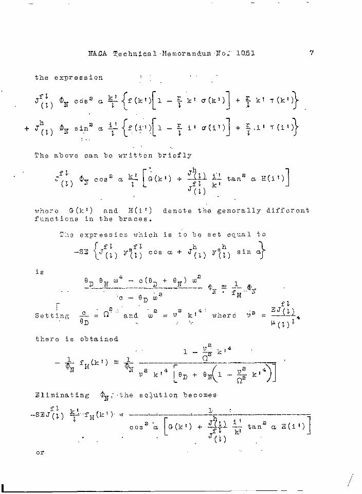
NACA Technical Memorandum No.:”10.51 7
the expression ,.:’
“{’[ 1 }+J~l) @N sin2 CG$,, f(g”) l-~ i.’cr(i,~) + ~.il T(i’)
:-,
The above can be written briefly
!,
f lr r’~h
J(t) $3T COS2 CL $: ~G(k~) + _# ~+ tana ~ H(il)
‘(2) .1
v:h9re G(k!) and H(il) den6te the generally differentfunctions in the braces.
!Che expression which is to be set equal to
_~E {Jft “f2 ,1h
}L (1) ‘(2) Cos a+ ‘~~) Y(~~ sin a
is
‘D ‘IT ‘4 – C(QD i- eN) W2–--––:–––––––––––--–––––– ON : J– @ ,. .
-’c— 9D W2fM-- N
~-\
~ ~2:”and ‘W2 = V2 kt4’EJ~~~
Setting c wher e v~ = –--– ~i; ., .!~.
~(t)z
there is obtained
Eliminating @N,”the so~utioq becomes
1- :-SEJ~j) $~’’fl,I(kI).& -———.-.————.:—-——.————--—.—,—.————---------
2’
.[G(kI) + J~tl !--!,tan2 ~ H(it)Cos a
jf~ k? 1. . (i),’or ..
i

a M C~ Tec?mica: Iiemoranduin No. 105 1,
‘.,
(6)
‘l’heetrans
x?resfor file
sion on the lefd into
t- hand side is coilveniently
21
,4-~=k
0 1----—- ——. -———— —-- - ———
(
e~ ‘ ~~
)
k 13l+-= l––-k~q
eD Qz
s ~(t) 23—.—-——.--——
6D(7)(k ‘)
.
It m, ins to replace -j, t 1)y in the expression
4iand
so that
Hence
Fs (1:1) .———- ——.————4
fl
H~-
‘(Z1 k———
J;2)
(8——9.
)1 ta
.--—— -
2na 1a [
LCOS2 G(kl )
1’
o*g~
x
5
-pO.e c
wit
shows the fv.nct ion FS (k;) for
ints of intersection with the axiharacter istic values ke’ for th
h the boundary conditions Ytn’
a= O and
s:of abscis–.e rod fixed
r =sas
at
Y,,1,(o) yll(o) o; y(t) o;
the values of kso I“orth.
The asynptoso forth, give thfor the boundary
I are 1.875, 4.694,
tic positions 3.927,e characteristic valconditions
‘7,
7’0ues
855, 10
068, 10ke !
● 996,
,210,of th
a
ae
nd
ndrod

—,____
NAC~ Technical Memorandum No. 1051 ‘ 9
y’” (o) = y“”(o).= o;” ‘yn(-L)= y(t) =0
. .. . . . . ...’
l?igures 6 and 7 show the function “~s(k~) “a =for O andr“= O.l i and 0,,2 i, respectively. While the zero posi–tions of .I’#kl) remain the same, the asymptotic positions
are displaced. This is explained by the fact that for thefrequencies given by,the zero positions i -the hub is alwaysat rest and therefore plays no part no matter how large ‘ ris, The boundary conditions for the rod are the same. ~ orthe asymptotic positions one boundary condition was y(l)=o.Actually, however, it is y(t) = r@N. For this reason the
-asymptotic -position must be displaced. ,
Figures 8 to 13 give the function FS(k!) for r = O0 0and a = O , 15 , 30°, 45°, 60°, 90° for a rati’o
Jh/JfZ = 16. Ti.gures 14 and 15 gi~7e the I?s(kl) functionf or a=60 and r = 0.1 1 and 0.2 1, respectively.
I“t may be seen that for the obliquely set rod the twofunctions FS(kl) for a = 0° and a = 90° are superposed.
Since the zero positions remain the same, the variousbranches of the curve must crowd together. The more one ofthe two i~rincipal vibration directions is turned out of thetorsional vibration plane, the more the correspondingcurves draw together. Xach branch of the Ts (k) curve
again runs, between two as:~mptotes. The corresponding valueof k’ gives for both vibration directions a compositeform of vib~ation such that the bending moment” of the rodat the blade root is zero in the torsional vibration plane.
The position of the Ys(kl) branches for the vibra-
tion about the chord depends on the ratio4
/
‘h“, :.’+1
4J(O
For J~~)/J~:~) = 16 the above ratio is equal to 2. The
zero positions are therefore at double the ke~ values .
of tb.e vibrations about tb.e small axis : that is, 3.750,9.388, and so forth. From this it may be seen that forthe ho,~ogeneous prismatic rod fixed at one end, the fun- sdamental vibration about the small axis is followed

10 NACA “Te9hnical Memorandum No. 1051
directly %y..the fundamental vibr tions shout the larger?1axis , provided the ratio J: A7J(7! is smaller than
(4.694/1.875)4 = 39,3., If ~~~ r~~~o is larger it meansthat the fundamental vilration about the longe~ ~ fol-lows only after the first harmonic shout the small~ axis.“This holds quite generally also for nonhomogeneous rkdsand hence for propellers except that the ratio J% \/J;?\
G(?K1)\i/]” \b)
and also and H(i~) ane different functions.
With each vibration of the rod there is thus” assocj-aied such a l?S(kl) branch - that is, since there aretwo vilration directions each degree is represented twice.1~.general, the Is(kt) branch corresponding to the nthdegyee intersects the k I axis at kel and at4
1
-—-..—L____
‘~z)/J~/) k’ if G(k’) and H(i’) are equal.
The function l?~(kl) is quite independent of thematerial constants of the rod. It is valid for all rodshaving J(x) and W(X] constant over their length. Allconstants of the crankshaft-rod system except for the ratior/ 1 and Jh/JfZ are included in the expression for
Ilt(k% This has the advantage that on varying a constant
only one function is varied and the relations are thusmora clearly scan.
.“
The engine fuzction possesses a zero and, if e~+ o,an infinity. The zero” - that is, the intersection ‘withthe
.--—kt axis, gives the natural frequency /_c7~~ of the
torsional componexit system up to the hul. The infinity
J
———z .-o~ + Qyj
gives the natural frequency c -— of the system:QD e~v
rotating mass - elasticity - mass of hub. The zero posi–tion depends olilj~ on the ratio v/<2● !lhe natural frequen—ties cf the entire system including tha rod ara obtainedfron the relation w = v kla , where the k’ are determinedby the intersections of the two functions TS(k~) and
Elx(kl). The validity of these relations was checked with
the aid of numerous tests with rectangular saction ironrods. Tigure 16 shows, attached to the shaft, the huh inwhich two prismatic homogeneous rods may be inserted atdifferant settings. From the ~S(k’)–YM(kt) diagram itis clear that through the coupling the natural frac~uencies(zeros of Flq(kl) and ~S(kl)) of the component systemsare displaced.

NACA Technical Memorandum No. i051 11
There ~~ill now he determined the natural frequenciesof a single-nass system with rectan~ular rod the constantsof which correspond to those of a 700-ho~seyower radialengiv.e. Let
OD = 10 crnkgs2; Smt2 = 1000 cmkgs2; !2 = 630s–1
(n = 6000 rpm) and in the first case eN = O, and in the
~ec~nd case 6i~ = 8D.
For each case the functions ~s a“nd Fiti are drawnfor a blade which corresponds in its dimensions to a largepropeller. oIn the function FS(kl), Jh/ Jf 1 = 16; r = O;and a=Go. In the function FM, V = 40. The first
case on figure 17 corresponds to the relations obtainingfor an adjustable pitch prop~~ller or for a noncontrollablepitch. l~;oodpropeller. The second case on figure 18 cor–r?spo:lis to that of controllable pitch propeller for whichti:e iKiSS moment of inertia of the hub may have the samevalue as that of the engine, There is thus obtained: .——
nl n=(r~;) ‘4
n5
Case 1 1530 5100 8400 22,600
Case 2 1530 61C0 8400 lCJ,ao~ 23,600—-— —.
For com-oarison there are given the corresponding valuesthat were obtained for a B!(’T–Electron–controllable–pitchproneller on a test stand s~milar to that of fig~re 2:f)D was equal to 11.7 kgcms , e~~= 6 to 9 cmkgs(estimated), G? = 550s-1.
—nl n2-
(r~~n) ‘4——.2000 5600 6100 10,800... . .. — —.—
The rod in each case possessed the vibration form obtainedby substituting the value ~1 given by the point of inter–section in the function y(x). It can only nossess itsnatural vibration form for one end held fixed if a nodeoccurs in the hub and the hub is thus at rest. This ispossible for the following values of kl:
Lrl i= 1,
The point
is then’ always
875, 4.694, 7.855, and so forth.
of intersection of FM with the lrf axis
simultaneously the intersection of an 3’s
branch with the -.17● axis. It is Seen that in thesecases the frequency of the entire system cannot vary if

12 NACA Technical Hemorandurn No. 1051
the blades are rotated in. the hub - that is, their pitchis varie cl. In all other cases the natural frequency ofthe entire system varies. It can only possess the formof vibration corresponding to the condition y!!(t) = oif the infinity of. the FS(kl) function coincides with
one of the FM(kt) function. All the vi%ratiori: over bothaxes can always %e excited as long as neither of the two~Jrincipa?. vibration planes lies in the torsional vi%ration)~c~ne. That the previous conclusions hold similarl~- foryopellers is shown hy fi~ure 19, which gives the varia-~ion with pitch angle of the first three natural frequen—ties of a. si~lgle—r.lasss~stem with rectangular section rod,a 3WM controllable pitch propeller, and an As-8 adjustable7Yo-~eller.
.
I’igures 17 and 18 show further that if tiie intersec–tion @f y
s with the u branch of 1?~,~ lies above thek! “a+xls, it means th:lt in the” torsional–vibrat ing systemtliere are u --1 nodes and in the “olade there are vno[l(.~~:herc v is the degree CI’ the intersected I?sbranch. If the” pbint of intersection lies below the jc-1
axis ~;,ere are u nodes in the torsional vibrating systemand v — 1 in the blade.
Tor ~3ractical purposes a ki~owlod~;e of the first threefrcquoncics is of particular importance, since the otherscan, only be excited .OY the high harmonics of the torsional–force oscill.ogracl which are very small. For this reason,it is sufficient to consider these first three frequenciesalone. ~n].;~two kiilds of ‘propellers arc possible: namely,these to tihich the fumkcmwntal vibration Shout the tih.ord,onaccount of the thin hub shaft, lies below the first har–monic- about the smaller axis and those for which the re—vprsc is tho case. .Fil”st , case 1 is considered. In fig–Ul”e 20, the first three branches cf the Ys(kl) function
for the prismatic–homogeneous rod are drawn for a ratioJh/Jfz = 15 and a = 60°, r =. 0. The corresponding r~~(kl)f71nction for a = ~GO is also shown dotted. The heavyCOntiilLIOUS curves are t?.ree FM(kl) functions . The first
represeilts the cas~ where tbe na,tural frequency of thetor~iollall>- vibrating systel; is lower than that of thefundamental vi-oration about the chord of the rod fixed atone e;ld. ‘The second function gives the case where it isequal to the first harmonic a~out the small axis, aild thethird the case where it is greater than that of the firsth:~rmoilics *
—~-””- “ “-”
.
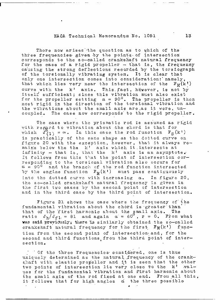
XACA Technical Memorandum No. 1051 13
There now aris,es”’the question as to which of the’three frequencie-s, given .by the points- of intersection’corresponds to the so-called crankshaft natural frequencyfor the case of a rigid propeller - t’hat is, the frequen-cyca:using the strong deflections recorded hy the torsiographof the torsionally vibrating system. It is clear thatonly one intersection comes into consideration: “namely,that which lies very near the intersection of the l’iq(k~)curve with the kt axis. This. j?act, h’owever, is not b~itself’ sufficient ; since this vibration must also existfor the propeller setting CL = 90°. The propeller is thenmost rigid i.n the direction of the torsional vibration andthe vibrations about the small axis are,as it were, un–
. Coupled. The case now corresponds” to the rigid propeller.
‘lhe case where the prismatic rod is ass”umed as ri’gidvith re~
$rd to vibration about the chord is that for
which (t) =CD. In this case the rod function Fs(kl). .
is yrac~ically of tb.e sane sha~e as the dotted curve onfigure 20 with the exception, however , that it al-ways re-mains below the the k I axis which it intersects atinfiniuy – that is, that the k f axis is an asymptote.”It follows from this that the point of intersection cor-responding to the torsional vibration also occurs for”a = g~o and the branch of the rod function intersected‘Dy the engine function J?N(kt) must pass continuously
into the dotted curve with increasing a. In figure 20,the so–called crankshaft natural frequency is given inthe first two cases ‘oy the second point of intersectionand in the third case by the third poiilt of intersection.
Figure 21 shows the case where the frequency of”~hefundamental vibration about the chord is ‘greater” than- ‘that of the ‘first harmonic about the ~mall axis. Theratio Jh/ Jf t.= 81 and again a’= 60 , r = O. From what
was said pte~i6uslyi there “issimilarly obtained the so-calledcrankshaft natural frequency for the first. ~M(k~) func–
tion from the second point of intersection~and, for thesecond and third functions, from the third point of inter-section.
.,Of the t’hree Frequencies- consi.ie~-edj one is thus
uniquely determined as the ilatu.ra~..fre.quencyof the crank–s.haft ,<Jithelastic ~~op”eller an-d it ~S seen that the othertWO pOiiltS of interjection lie ver”y close to the kt .Val—‘~es for the fundamental ‘vibration and f’irst harmonic aboutthe small axis of the rod fixed at one end. Trom all this,it follows that for high angles & the three possible
e’
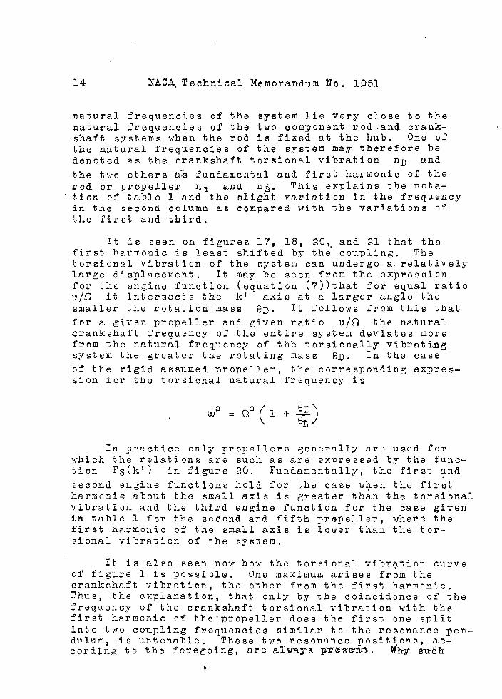
14 NACA. Technical Memorandum No. 1051
natural frequencies of the system lie very close to thenatural frequencies of the two component rod and crank--shaft systems when the rod is fixed at the hub. One ofthe natural frequencies of the system may therefore bedenoted as the crankshaft torsional vibration nD and
the two others a% fundamental and first harmonic of therod or propeller n~ and n~. This explains the nota-
‘tion of table 1 and the slight variation in the frequencyin the second column as compared with the variations ofthe first and third.
It is seen on figures 17, 18, 20,. and 21 that thefirst harmonic is least shifted by the cou~ling. Thetorsional vibration of the system can undergo a. relativelylarge displacement. It may be seen from the expressionfor the engine function (equation (7))that for equal ratiov/n it intersects the k’ axis at a larger angle thesmaller the rotation mass 6D. It follows from this that
for a given propeller and given ratio v~!a the naturalcrankshaft frequency of the entire system deviates morefrem the natural frequency of the torsionally vibratingsystem the greater the rotating mass OD. In the case
of the rigid assumed propeller, the corresponding expres-sion for the torsional natural frequency is
In practice only propellers generally are used forwhich the relations are such as are expressed by the func-tion Ts(kl) in figure 20. Fundamentally, the first and
second engine functions hold for the case when the firstharmonic about the small axis is greater than the torsionalvibration and the third engine function for the case givenin table 1 for the second and fifth propeller, where thefirst harmonic of the small axis is lower than the tor-sional vibration of the system.
It, is also seen now how the torsional vibrqtion curveof figure 1 is possible. One maximum arises from thecrankshaft vibration, the other from the first harmonic.Thus, the explanation, that only by the coincidence of thefrequency of the crankshaft torsional vibration with thefirst harmonic of the-propeller does the first one splitinto two coupling frequencies similar to the resonance pen-dulum, is untenable. These two resonance positio~.s, ac-cording to the foregoing, are alway% IEIT&S@’IUb.Why Suijh
b

.
NACA, Technical Memorandum ~fo. 1051 15
characteristic is so rarely measur,ed, and why the vibra—tion form of the’ propeller for the second and third
.frequencies of table .1-may be similar ,will be shown later,Furthermore , the torsional vibration frequency in adjust–ing the blade to high pitch angles must drop because theblade is then set more and more with the wide side in thetorsioilal vibration direction and thus becomes less rigid.In order to see this, consider figure ’20. High pitch “means here that CL->o. For the engine function III andII there actually is obtained ‘a lowering of the torsionalvibration frequency. Stmilarly, for the engine function Iin the case drawn where the natural frequency ~ of thetorsionally vi”nrating system is greater than that of theblade about the chord (Ice’ = 3.750). If the engine
function I, ho~rever, would cut the k] axis ahead of~e ! = 3.750 the torsional vibration frequen-cy would rise
in setting the blade to a high ‘pitch angle, according tothe rule estal)lished here, that all natural frequenciesof the entire system with increasing uncoupling of thetorsional with the flexural vibrations are displaced to-ward the natural frequency of the blade vibration whichis uncoupled. (Sen fig. 19, As-8 propeller. )
It will now be shown further how the solution (6)goes over into that for the rigid rod as V approachesinfinity. This does not show up in the Flt(kt) ‘%0 FS(k?)dia~rams. The greater the Value of V the steeper thefunction r~~(kt) for constant n, and its point of inter–section with the kl axis lies always more to the leftat small k! values . For the rigid rod (v = ~) it would.——_lie at k! = d w/v = O and the natural frequencies wouldassume the indeterminate form w = O X co although wobvious],y can still possess also a finite value. Thelimit must.therefore be obtained from the formulas. Forthis purpose the solution (6) is written
In this way, in the expression on the right , only k!occurs and on the left, only the product V k@, which maybe set equal to w. There is then obtained
I,,.-,,-,- —--, ,,,,,, , . —. ..—.-—-——, .——— - .. .- - . ..-

. .. .
,.. ./..
16 ,, “ NACA Technical He;loralidum No. 1051.. ..
,,
and. settin~ for simplification, m =, 0, r = O - ... .
,. . .~ 1#’”
ILJkq !$+3 ., ’-----––_..________T__L ________.Sinh !cI coskl - Cosh kl sin kl-,
When O approaches infinity kl will a’pproach zero, andit is only ~ecessary to in~-estigate the expression for tkerod function, ‘The’lat,ter is indeterminate. If the dcli~~]-inator , however , is expanded into a series , then
——-.-——-———--- --—-- -—————--— ...——-———..—..—_ ___—— ______ _____,,
(3
k! – –2–J:t __4_.k 15+. ● m\_3 5
)( )k!+_2_k I __4_]cl _ .. ‘
~: ~J 3! ‘ 5!
and for ],cl= o , the value of the fraction ‘oecorfiesequalto –3. ‘The solution for V =, m then hec ones
I-n solving for u.),the following ~quati,on is then obtained
The expression in the first parentheses is no other ,however , than the mass noifientbf inertia – referred to theshaft — of a “propeller 1’co:lsisting. of a prismatic infi–nitel~- rigid rod and may he set equal to 8L. Then
eL (w’ - ff)= f++? -, ,

NACA Technical Memorandum No. 1051 17’
SOLUTION FOR NOitHOMOGENEOUS RODS
Having discussed the prismatic homogeneous rod,there will now be investigated how far the computationmay be carried through for the nonhomogeneous rod.Start from equation (3) and write
The difficulty of solution of this differential equationincreases with the complexity of the functions P(x) andQ(x). Tor this reason there will be set for P(x) a~dQ(x) the sirplest, yet still reasonable exponential ex–
pressions,() ()
P(x) = ~ p and Q(x) = ~ ‘. Dividing the
efl_uation by P(x) arid scttirig p+ c = q, there is ob–tained
In the above differential equation p can take any valuesfrom -~ to +w . Tor i-m > 6 ~ -4 ft is a Tuchs–typediffer{;ntial equation and as such is integrable by meansof series. Solutions d.efiued at X=o are obtained onlyif t~le i coefficient in a differential equation of theform
Iv
y(x)+Rl ylfl
(x)+ Rz Y~x) + R3 Y/x) + R4 Y(x) = O
has a pole of, at most, the itl~ order. If CC–4 thenx= o is a so–called essentially singular point, and forthis case there is as yet no complete theory. (See L.Bierberbach, Differentialgleichungn , pp. 195-196. ) Atany rate , no solutions can then be found in the form ofconver~ent series. Thus , the cases are restricted tom > c ~ -4. Since the case C = –4 is solved by settingy(x) = Xp the method of series development starts withc = -3 ● Since only in the cases with _~’~> = —3 not allfour particular integrals involve logarithms, of whichuse cannot be made, the solution of the differentialequation is restricted for +CO > p> -m and m =’ c ~ -3.

18 NACA. Technical !’le’mora”ndtim’No. ‘~051
m
setting y(x) = Y 3,1 ZP+’V) tkereis”obtained, st-nze
“;the “characteristic equation”a. is not to vanish,
Tiie 2“oove equation l~as the fcur rootso

II------ .. q~------q.. , ... .
.,. ,....
e’
. .
I

20 MA. CA Technical "eir,orandum Ig o. 1051
It can roadil^r be shown that these series are convergent;m
a o and a, are constants and P denotes the product of
M factors, wherein the expressions m, runs from 1 tom. On account of the first and second boundary conditionin the present case, y° t (0) = y r' (0) = 0 only the seriescan be used where E 0.
On satisfying the third and fourth boundary condition
y^l) = r,^T cos a (or sir_ a); ,y (ti) = r^N cos a (or sin, a)
there is obtained the function F C (k r ). In the latterG(k t ) is then
c { yt )^ 1 H (k. r (kI) *.-,(k')] — kr( .^o I (k t ^r(krl -- ^110`4 (l.r)^,r(^r)]
andif r = O
V,^ (1';. L,'fl (^-T) — C o rr (kI w^l (-r)
y 0 (- r ) Lr l r (c r ) — 0 r ( k r ) 1 ( k t )
similarly for E(ir).
Figures 22 , 23 , and 24 show the curves. of µ (x)Jf7 (x), and i h (x) for two metal propellers. For these
T) = 6 and a = 1 or 1.5; that is, E _ — 5 or 4.5. Inorder to avoid fractional exponents in the second case,
there can also be set p = ^. Up to about X ':,7
both µ(v) and J(x) can be represented by straightlines — that is, p = 1, u = 1, E = 0. For this case,the solution is
y (X) = a o ^j o (k--x) + a, ^b_ (kx)
'x 4 ^8 x 8 Y12 x1 2k Y
o (k x) = 1 + ---=-- + ----------- + ------------ ----- + .. .3 x 4! 3 x 7 x Q, '̀—x 7 _x _11 x? 2!
1 1 x 5 1 x 5 x G
/ ) X5 k9 x9 -- ------`13—g13----4. x 5! 4—y —8 x 9! 4-X-8—x—, 2 x 13 !2 2 x 6 2 x 6 x 10

—.
I “—- –
NACA Technical Memorandum No. 10’51 21
~i~;~re 25 ~hows, +jh~’ Ts(kt) curre f or the fundame-n-. . . tal, vi-~ration CL = O and r = 0. Although five terms of
the power series were taken, it was. not possible to com-pute exactly the second zero position; because for highervalues of. k I the COmpUt:Lti OiI becomes too inaccurate onaccount ,of the rap,idly increasing large numbers . Thevalue must lie between 5.2 and 5,4. T,he first zero -posi-tion is obtained as 2.67. The corresponding experimentalsdtup is shown on fi-gure 26.
The first zero position f’o’r,nonhom’ogeneous rods can.
easily be found by the Hay;eigh metho’d,b
[
a
2<E J(t)wp(~) qx) ax
= -————— —,—-__-____-— -—-—
~(l) ! Q(x) Y(x)’ dx
y(x) = X-l+ ax3 + bxa + CX+ d
With the boundary conditions
-Ylll(()) = ~rll(()) = (-J;Yl(z) = y(z) = ()
Y(:i) becomes y(x) =x4- 413s+3t 4. There are thuso}t:% ined the first zeros for the following five cases:
. ... —
q P
,: HI-c ~1
e (p%wlt )————..—.—_—_—_ ——-..—————————.-- .. ..-.—— —————————----
0 -. 0’ 0 1,880 0.271’ 1 0 2.69 .751 2- -1 2,59 ‘
‘1 4 –3 2,4s1 6 -5 2.31————— ————— — .—-— —-—— ——————..———————— -—-———-—————
It is seen: that the first zero for ‘propellers Dustlie iri the neighborhood of 2. By the Ra~le~gh method itis.also possible to approximate very closely the functionsw(x) and J(x) by sui~ble polynomials of x instead ofthe simple expression -, or xq so that tlie first zeroscan al?llostaccurately be obtained, as the pos’itive errorsholrs for 1,880 as compared with the accurate error value1.875. Unfortunately, nothing has been gained t~ereby

—
’22 .NACA Technical .Memorandum No. “XG51
for the problem ‘under coiisidwation; since from all thathas been said it is ‘net practically possible to computebeforehand the natural frequencies of a torsional-f lexuralsystem as was done for the homogeneous prismatic rod.The only ”magnitudes that can he accurately determined are6D and c; e~ and r/ 1 are no longer uniquely deter--
mined. For the longer and shorter axis O.{?) and til(x) ,
respectively, can be found only approximately, and thefunction r#) can %e ~ractically computed only for thefundamental vibration, ;which is not of great interest.There is the further difficulty that the angle a on ac-count of the twist cannot be accurately defined. 1?orrelations such as those holding for engine function I onfigure 20, the angle a = O also can be defined as thatfor which the frequency of’ the first harmonic is a mini-mum and for the fundamental vibration a maximum. A cor–responding consideration holds also for the still higherharmonics. This angle in practice, however, deviatesfrom zero,as tests have shown (see p.26) and has differ-ent values for the different vibrations. The deviationfrom zero may be as much as 30 . This necessarily leadsto the direct measurement of the natural frequency ofthe crankshaft-propeller systen. The test setup, however,must permit a variation of the elasticity and the momentof inertia of the rotating mass in order that the cor-responding engine may be simuIated with sufficient accu-racy,
MEASUREIjEITT OF A PROPELLER
In order to be able to satisfy the condition of ac-curate simulation of the engine under consideration, thetest setup was constructed as shown in figures 27a,b. Arotating mass to which is screwed the unbalanced exciterweight is displaceable on a steel shaft 120 centimeterslong and can be held in place by a pressure seat. Themass moment of inertia can be varied ‘Dy screwing on ironplates, each of 1.1 kgcms2moment of inertia in steys of2.4 to 15 kgcmsa. With the aid of this apparatus; it ispossi%le to determine, experirientally, the unknown func–tion I’s for the range of practical importance. Thereis first determined the value V for the’ propellerunder consideration. For this purpose there is taken inthe neighborhood ‘of the blade root a cross section, whichis typical of the remainder of the blade (fig. 28).
—-,,. , , .- .,-..-..---- ...!.... I -.-, .-,-. .!. !!! . ! ! . ! .!- —,, -,., . . ,—.

—
NAGA Technical Memorandum N-a.,105 I 23
,
There is i~ow dra~ifithrough the k? axis’ a fanily of. ~~~(k 1) ‘‘curves” by va=ryi-mg -&D .,0and. c. .Ea.ch..time.the
corresponding value of ep Land c is adjusted on the
test stand and the frequency w measured. Then, for
feach k!- = ~ on the corresponding FM(kl) curve a
vpoint is marked. The line joining all these points givesa portion of the unknown propeller function FS(kl) not
not computable in advance .
This yrocedure was carried out for a Ju PAK–duraladjustable propeller for the 3MW “Hornet!! engine. Theblade length was chosen 1 = 110 centimeters and thellade width was then obtained as b = 25 centimetersand %lade thickness h = 5.7 centimeters. The ratioJh/ Jf 1 at the position x = 1 was 16.3, The;mag@&m&e3 was ~omputed to ~e approximately 70,and the values W(T)Z=, 743 kgcms”. The mass moment of inertia of the
hu% “with blade root was 4.93; r/10.15.
was approximatelyOn figure 29 the various engine fuilctions
1 4900 ~14- —-——
(k!) = ~D3 rr 1
%——... -.—.- .--.———-—-—— ----- ___
( )
~+ 4.93 ~ _ 4900 ~14 k13——-
‘D(22 ‘
are denoted %y the letters a to “ k. On table 2 thevalues of e~ and ~z are given for each of the 1(3
~ b{(k’) functions which were adjusted on the test stand.
On figure 2“9 the, similarity may be seen of the propellerfunctions deterrniued by this test with those of the homo–~eneous prismatic rod on figure 14. It is to be notedthat in the latter figure ‘the scale of abscissas wassmaller. For the Ju PAK propeller the different harmonicsfollow each other more rapidly than for the homogeneousrod. There were obtained the values nl = 2800, n2 = 7300,n~ = 13,200 rpm. For the BMW Electron controllable pro-peller used for comparison, there was obtained nl = 2000,n2 = 6100, n~ = 10,800 rpm. .
The test showed that the first harmonic is practicallyindependent of the torsionally vibrating system. For thisreason it might be computed in advance if it were suffi-cient to compute the frequency of the blade fixed at theroot , as is possible with the aid of energy methods (ref—erences 4 and 5). The assumed rigid end condition at the
. .....-- ...-.----. —--. . .... . . .. .... . ,,,....,..,,,.,.,, , ..... ... --- --— .——

.24 ITACA ,Technical Memorandum .No. 1.O.51,.-.
root, .howeve”r, d~es not actually occur and the degree off ixing , wh-ich can .De @.iffer.e”nt f or “each hu% , g.reat~y .,af-fects the frequency. The effect’ of the twist which tendsto i:~crease the frequency must also le taken into ‘account(reference 8) : I?”orthis ~eason, the experimental me”thodis preferred, ,whick enables the simple and accurats deter-mination of the ‘r,equired frequ.enby, J ,’ :
In’this eonnectio.n,-there will also’he considered’thefactors that affect the first characteristic value ket
of propellers. For the Ju PAK propellers for a value ofv Qf ’70, this,value of ket lies at 2.06. For the pre-
viously mentioned ‘BNW propeller for’s value of U of 50,it lies at 2.05; and for the As-8 propeller of figure 19for v = 70, “it’ lies at 1.93. The characteristic valueske I for known’n&tural frequency depend on the choice ofthe nagnituae V- and tb.e latter again on the choice of
the position x = 1. The change in the value of v isvery marked only where the 31ade passes over into thecyliilduical shaft, where 1? increases yery strongly. Ata distance of 10 centimeters along the blade, however , itis already only slightly affected ‘OY a chal:ge in 1. .Theblade naturally can be considered also as extending tothe poimt- of .attachmenfi. This , in the case of the Ju PAKpropeller, would lead to a val-.zeof v=88 and the ke 1
values all would be. si~aller 3Y 11.2 percent. Tb.e I’s(kt)
function then also must change a little but, on the whole,will be very si:(,ilar. ~he ~:I values would then depend,however , only ,on the form of the section at the positionof &ttacilLOent.- that is , with a thicker shaft the .%lade
‘would nave much lower characteristic values, This ,however , is physically unreasonable. Hence the shaft mustbe coilsidered as ‘DelOilLing to the fixation and not as apart of the elas’cicit;~ determining the natural freque~ciesof the blade. l?or this reason the ,FS(k~) function forthe Ju YAK ~ropeller was determined for the value v = ’70.
‘ ZFI?ECT Ol? T.HX CdUTRIFUGA.L F.ORCll
. .
A test setup of the kind descriled alove gives onlythe na~uz’al frequencies cf the system for the case of a‘:uonrota”tingpr,opell~-r. There also must; l)e taken intoa,-c~,ount , therefore, t~e increase in the stiffness andhe,nce ‘the natural frequency of the blade as a res’.~ltof
.“.’ .,.
NACA Technical Nernorandurn No. 1051 25
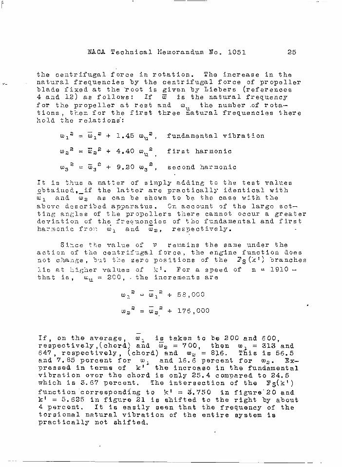
the centrifugal force in rotation. ‘The increase in the.–- natural frequencies by the centrifugal force of propeller
blade fixed at the “root is given by Liebers (references4 aad 12) as follows: If 0 is the natural fi-eq,uencyfor the -propeller at rest and Wu the nuiflber.of rota–tions, then for the first three natural frequencies therehold the relations’:
WI= = G1 2 + 1.45 WU2, fundamental vibration
W22 = m2~ -1-4.40 WU2, first harmonic
LU32
= zz~ + 9.20 f.u32, second harmonic
It is thus a matter of simply adding to the test valuesobtaiiled, if the latter are practically identical with—W1 and W2 as can be shown-to be the case with theabove described apparatus . On account of the large set-tiilg an?;les of tile propellers there cannot occur a greaterdeviation of the frec]uencies of the fundamental and firstharmonic froI: ml aad ~2, respectivel:~.
Since the value of V remains the same under theaction of tile ceiltrif-~gal force, the engine function doesnot cha;~ge , but the zero positions of the Ys(kt) branches
lie at higher values of k’. For a speed of n = 1910 -that is , wu = 2C0, . the increrneuts are
WI 2– 2 + 58,0s0= WI
2LU2 – 2 + 176,000= W2
—If, on the average, wl is taken to be 200 and 600,respectively,( chord) and Z2 = 700, then wl = 313 and647, respectively, (chord) and w, = 826. This is 56.5and 7.85 percent for WI and 16.6 percent for W2 . Ex–pressed in terms of kl the increase in the fundamentalvibration over the chord is only 25.4 compared to 24.5which is 3.6’7 percent. The intersection of the I?s(k?)function ’corresponding to k! = 3,75”0 in figure”2”0 andk! = 5.625 in fi~ure 21 is shifted to the right by about4 percent. It is easily seen that the frequency of thetorsional natural vibration of the entire system ispractically not shifted.

26 NACA Technical I“Iemorandum No. 1G51
SULUT ION I?OR.A S31VER.4L--MJlSS SYSTEM
There is still to %e investigated how the naturalfrequeilcies are determined for an in–line engine whichcan he represented only by a several-mass system.
Let the system consist of 6 masses – correspondingin their dimensions approxi~ately to the BMW-IV engine.
9 1–6 = 0.5 kgcmsa
c~_5 = 4 x 10⁶ kgcm/rad
C6 = 2.66 X 10⁶ kgcm/rad
The first three natural frequencies of this system thenlie at
(2= = 635 Q2 = 1895 n3 . 31OC)
In order to simplify the computation, somewhat, each pairof,masses is combined into one ‘(fig. 30) so that
0~
1–3 = 1 kgcms
C,3= 2X1O 6 kgcm/rad.—
The first three natural frequencies are then computed fromthe equation
,. 6 4 12 2107XUJ
le.cJ,– + 24 X 10 XW -’8 X 10 = O -. .
.,
!sl = 630 r?ompared with 635 - 0.8 percent
f22 = 1750 cor,paredwith 1895 - 7’.7 per”cent
‘ 33 = ‘2550 compared with <100 - 17.8 percent
This deviation is of no significance for our ‘investigationand is given only as a matter of interest. NOW consider

NACA Zechnical Memorandum No. 1051 2’7
the three-mass system. The other magnitudes in the l?l,I(kl).-. —. -
function are assumed to be
v= 30
}
which values hold- for very large
s ‘(l) ‘3 = 1200propellers.
The fui~ction FM(kl) will now be computed for two
cases. 1,1 the first case e~ = O and in the second case0~~ = Z’Oi (fig. :1). It can be given, in general, for anar’bi.trory i~umber of masses if the method of Tone is used.TF~is method serves to co,n~oute the natural freq,uendies ofa several-iflass system. If 1’ denotes the moment and athe deflection of aily mass, then
~JIi,i+-1 = ],1i-l,i -GiW2ai
1.1.l,i+lai+l ‘ ai + -——-. -
c.l,i+l
Thus st:rtiilg at the end mass
al=l
el U)2a2=l - -———-
CIQ
M23 = M12 -e2w2a2, and so forth,
if , however , all ai are expressed by al and all“!4”z ,’i+l- by M12 expressions “of ter’ms w’ith increasing power
of the natural frequency are o’btaiiled

28 I?ACA Technical I!emorandum No.. 3051
elw2az = 1 -------
C12
4 ele~1123 = - w2(e1 + ea) + w —- —-—
C12
1131=-––––––––”- –-–––---– –-–
The function for an n mass system may theil le writtenas
where ~a = O gives the zeros aild Mn n+l = O the in=-n
finities of the functions. There are ~btaiiled the values:
Case I First zero c1 = 630 k! = 4.58l?irst infinity w = 1420 k 1 = 6.88Second zero ~2 = 1’750 .K = 7.651- 1
Secoild infinity u) = 2450 k! = 9*G5T~lird zero o“3 = 2550 kl = 9.23
Case II First zero C21 = 630 k! = 4.58 “First infinity k I = 5.32Second zero rJ; : 1;:; k! = 7.65
Second infinity w = 1845 kl = 7.85Third zero (23 = 2550 k! = ~.23Third infinity w= 2580 k! = 9.30 “ ‘
Figures 32 and 33 show the variation of the “F~,l function
(continuous curve) . The three masses were now combinedinto one and the elasticity so chosen that the natural
.-. .,.P ,,.,.., J. .,---.,.. .!.:.. ,> T,, .L. .

NA,CA. Technical Memorandum. i~o. 1051 29
frequency of this torsiofially vibrating system was equal.t0 .thc-f.ir.st.:~fthe t~,~.e.e.-rn.a.sss.ys$em:.@> .
c = 3,a12
The substitute function for the fii?st case is then obtained
.;. ,., .,,,.1
‘-400 ‘ :3T~I(kl) = ;Tz (1 - 2.27 X 10 k14)
,.
and for the second case
‘’400 1Flu(kq = --~ - 2.27 X 10⁻³ k14----- -.---—..---—k12_ 2,27 X 10⁻³ k14
“(qp) = 4~58; k ‘,(F*~=uJ)= 5’45
,,
Sine’e the substitute functicn first begins to deviate fromthat of the three-mass function only at a rather greatdistance from the k t axis , where the Fs curve runspractically vertical, no difference in the values of krCiven .h~rthe intersections can occur up to about k’ = 6.Since the first zero is at 4.58, it means that the equiv—alent system correctly gives another natural frequency,which lies- higher thail the first natural frequency of the
2 2-
System (j’l ~y. ~––~--~+- x .100 = 71.5 percent - or4.5,8
in’round- nv.mbers - ’70 percent. Thus- the higher, frequencyshould be not” m.uch gr’aater than ,
.!,,,,. \
,, n’= 6’)800” if nD =’ 4.,000 ,
n = 10,200 If n~ = 6,000n= 17,000 if nD = 10,000
;I-fJ>*tLheAdifferenceJt~ greate’r then, “havi-ngdetermined theTS(kt) function on the test sta;nd, the engine functionis accurately computed or, at least, replaced by the one=,tl,ro–,or three-mass system and then Lfladeto intersectwith the ,FS(kf), function..

.. . .. . . . . .. .. . . .. . . . ... . . . . .. ,..,,.,, .
30 NA-CA Technical !~emorandurn No. -:1051
This cone’lude”s’the investigation of the problem o-fthe coupling of the flexural propeller vibr-ations withthe torsional crankshaft vibrations and the determinationof the critical engine speeds. In the following therewill be further considered the fundamental stress problems.
THE VIBRATION STRESSES IN THE SYSTZM
A. Theoretical Considerations
In the function Fs (k I) zeros are followed by in-
finities. I’or the vibrations corresponding to the latterthere hold simultaneously the three boundary conditions
y’” (o) = o, y“(o) = o, ,y(l) = r Ox?
m,.ne fourth condition, corresponding to the zeros, isy!(z) = o. For our system this means that the hub is atrest anti the greatest bending w.oment is at the blade root.In these cases the propeller blade vibrates mainly ab”outone of the two principal moment–of–inertia axes of thecross sectioil. Without twist a rod or propeller %ladewould vibrate a“oout ore of the princi~a’1 axes ‘only. Theeiltire system vibrates with the frequency u) = ~, therotating mss undergoes relatively the greatest displace—ments and the component of the largest bending moment ofthe rod in the torsio~lal vibratioil plane a’mounts to
The torsional component-system is in resonance. As a re-sult of the twist torsional vibrations of the hades maybe e:;cited, hut these vibrations will not here be con-sidered. It may be remarked in passing that they have,up to the present, been very rarely observed. At the fre–q,uency corresponding to k! = 2.97 in figure 29, thepropeller blade would thus vibrate in its fundamental modeabout the chord and at the frequency corresponding to1;t = 3.3 in its first harmonic about the small axis. Tothe right and left of each zero of the, lF3(kl) functionthe i~ornent”at the blade root. again decreases, the maximummoment however no longer lying in the direction of, one ofone of tfie principal moment-of-inertia axes of the crosssecti’on, s~nce a moment now arises about the other axis.In addition to the frequencies corresponding to the zeros,

,,NACA Technical Memorandu’rn No. 1051 31
vibration. of the rod occur simultaneously over the two.aiZC?S.ai~d the two, moments- in these directions togethergive a resultant moment 1,1 which makes an angle Pwith the torsional vibration plane. (fig. 34). This re–sultant L~Olllentmust be decomposed into two perpendicularcomponents , one of whi’ch,acts as a pure lending momentMB on the shaft. On account of the symmetry in the case
of several blades,these bending moments balance eachother’ o-tit, but the shaft is dcted on’%y a te~s’ile or com–pressivq force through which axial vibrations of thecrankshaft may be excited (fi’g. 35). The other-componentMD just balances the torsional vibration moment in theshaft. It follows that, since the torsiograph measuresonly this one component that the moment in the hub is tobo assumed considerably higher.
Tor tile vibrations of the rod correspondilig to theinfinities the fourth boundary condition is ytl(t) = o.In this case the %ending moment at the blade root isequal to zero and the hub is in motion. These vibrationmodes can then only arise if the two infinities of ther@r) and FM(ki) functions coincide. This is possi–
ble if the mass moment of inertia of the hub is not equalto zero. The frequency of this vibration is given by
/
J“eD + 6~
w= c –——--—––9D 6N
and the an~ular displacement of the hub has its maximumvalue . The maximum occurriilg bending mo~fientthen lieswithin the propeller blade~ All the blades would thenbe , as it were, in equilibrium; and the rotating masswould only have to balance the moment due to the vibrat–ing hub. Since
for the displacement of the rotating mass, there is ob-tained -- “,
.

32 NACA Technical Memorandum No. 1051>.
which therefore decreases for given hub displacement astke ~atio, of th&hu3 filassto tlie rotating mass. The’ hubdisplacement’, ’,howeveq.,cannot become large, for,,
...,
.,.
On account, of the.setting angle CL, ~hy (1)
contributes
I?or U = 450,, ,h~most to t-he angle ax” ‘(2)‘Y~:~; but
‘h (a= 90°) is small compared toy~l) Y[~j (a = 0°) since
J(t)< also at the blade root is much larger than J?;),
Moreover,&
must bec’ome smaller the more the resonance–
indicating value of kl , for the prismatic homogeneous rodhere. considered, differs – for example, from k! = 7.853.Hence DN for the vibrations corresponding to the infinitypositions is small making ‘D also small, since the ratio
ON/QD ‘is gel~erally. smaller than 1. This holds,als,o,.
approximately for the cases where the point of intersectionOf ??M(kt”) with ??s(2s1) which poir.t de:srmines hhe res-
onance frequency @f’t-he sysie?o lies far from the k’ axisand there is a node in the shaft. These points of inter–section always lie below the k! axis.
The displacements of the rotatins mass for the vi-
brations,the correspondin~ point of intersection of which. lies above tlie kt axis , are mu’ch greater than ~~ and
there is no node in the shaft.
The position of the point Of inte~s@ction of theengine and rod functions determines not o’filYa resonant@frequency of the crankshaft–propeller system but its dis–tance from the k 1 axis is at the same time a measure ofthe :Ilomentarising in the hub,because the magnitude
3M(H) = T@l) represents the l:eci’procal value of the
component of the moment at the hub divided by
which acts in the plane of rotation or the propeller disk.
-- -----------..----—--- - ..... . . .

“,NACA”:Technical, lIemorandum .No.,.,1051 33
Hci~ce, the closer the point of intersection lies to thek! a:iis the larger is the moment. This is seen with the ●
aid of figure 36, where the ~s function is plotted for
a= 00 and a = 60° and, furthermore, for a = 60°for the case that the blade is hinge-connected about thechord aild hence a momeilt on the shaft can be transmittedonly over the smaller axis (dotted). In the figurd! arealso given three engine curves, one of which representsthe case that the natural frequeilcy of the torsionallyvibrating system is equal to the first harmonic of theblade a’oout the small axis. This case will be consid–ered first (curve II): For the angle a = O the bladevibrates about the small taxis in the toi-sional vibrationplane of the hub. The moment in the hub is obtai.led.asinfinitely large. Sirlce in the actual case there isdanpin~ a finite deflection wi].1 be oltained for the rodand tlic iorsioilalljr vibrating mass . Let the defle~tionof the mass be ‘DO* The interlsity of the rod vibration
OilCh@,i!&iilg the an~le m cannot increase , therefore, fortll~ case of constant excitation. For any angle the nat–ural frequency of’ the system does not vary, since thejoint of “i:lt,ersectio]~which deter!~,ines this frequency re–mains the s3me . There is also, therefore, no change inthe mode of ~;ibration of the rod about the small axis andtlie mo:!lentin the blade root. In the torsional vibrationplane , however , a c0i71p0nent of the molflen’tis still effec–tive and hence the balance moment of the torsionallyvibratin~ mass 8D W2 @Da must decrease, Since e~ and
w are co;~stant
,,!lhe case is otherwise for engine curve I. With the
blade hin~ed about the chord there is a chan~e not onlyin the frequeilcy and hence the Jfiod.eof vibration of the%lade but alSO the ?LiStanCe of the new point of intersec-tion froii] the k’ axis is greater aild the moment there-fore smaller (fig. 37). The deflection OD of the
torsionally vibrating mass therefore decreases fasterthan as Cos a,’”.In this. case. the angular deflection att,h,ehub is ilot equal to zero. ~rolo equation (4) therefollows the relc~tion
:,,$, ,.
‘D = %
---- ..
.
1 ,-—————-
.’pg
Q
——.. .- .. ——..-—

34 ~ NAI)A Technical Memorandum.No. 1051 ‘
>. ~so that. for ‘the-angle u = O. --- ..”
. . .,,.1’ ‘
‘D ~= @N ——.— --,,
!. 0 1 - :+:’Q
and for the an-gle. a
or
q) = @N 1---——a
al~a2
- -——
c12
The ratio ONa/@No is a function of a, It may be de–
termined as follows. The formula must also hold if U.).
approaches O – that is, for the case first considered.~1’or that case there was obtained
The fraction
& - LU02—-—-——
Q2 - L#
approaches 1, if W. approaches Q. It follows that
ONa/@No approaches cos a. As may be seen from figure 36,
the moioent in the hub in the case of fixed end conditionsdecreases still more than for hinged end conditions. Thisnot only shows up in the expression for ‘Da by the de-
crease in the fraction but also in the fact that the ratioqlTa/@No .,always remains below cos a. The reason for this
;hwas,already given alove. The more y (2) falls in the
torsional vibration plane the smaller @ N~ must bec,ome
(fig. 38). The angular deflection ON of the hub thus
decreases more rapidly than as cos a, and hence @D fur–
ther decreases. ~ ““‘ .’.. ..

NACA- Technical Memorandum NO . 1051 ,35
Tigures 39, 40, and 41 show the variation of thea’n~ular ?Lefl~ction of the rotating mass Of a single-masssystem. f’or’,the case of the rectangular section rod andfor the propeller. The analogy of the propel ler. and rodis cle=ly. evident as already seen in figure 19, A com–parison with the latter snows that for the cases wherethe frequency was constant or.approximately so, with.chanqe in the an~le a, the angular deflection of therotating mass decreased. in proportion. ‘to Cos a, . In allother cases the deflection decreases at a greater rate.The indicated angle is ~nly a relative one in order tobring out better the analogy with the rectangular rod.The greatest absolute deflection of the rotating massmeasured in the center was obt,ained at an angle of approx-imately 15° for the fundamental vibration, 0° for thefirst harmonic and 3G0 for the second harmonic.
It should be observed that the above described de-pendence of the deflection a~~ on the angle a holds onlyfor cases represented by engine curves I and II. Forcases represented by curve 111 this holds true only forthe fundamcl.tal vibratj.on, but not for the torsional.vibration and first ,harmonic. For a = O there is thenobtained a greater first harmonic about the s,mall axisand the second node lies in the blade and not in theblacle root. With increase ia the angle a this vibra-tion goes over into the torsional vi3ration, while it is‘still represented by the point of intersection of enginecurve III with the second branch of the FS(kl) curve.
In the case, therefore, that the torsional vibration ison the opposed side of, the first harmonic, like the fun-dalilental vibration of the blade fixed at one end aboutthe chord, the moment at the hub in t~e torsional vibra-tion plane decreases’ somewhat with decrease in the a.~glea’ lut the angular deflection @D of the rotating mass
and hence also the m~ment transmitted IIy it to the rod,need not decrease because the motion of the hub can in-
crease through the increase of,f2
‘(t) ‘n %?” ‘his ‘sthe case for the torsional vibrations represented in fig-ure 20 by engine functton 111 and on figure 21 by enginefunction 1.,
For the first harmonic in the case of engine func-tion IIZ @D is small although the dependence shown infigure 38 of the hub deflection on the angle a no longer

36 NACA’Technical Memorandum No. 1051.”
applies ,becaus6 it decreases with “further decrease-in a.The. i%t’ersected- Ys(ki) curve then deforms into straightlines a<nd the tioint of intersection trawls furtherupuntil for this branch of the.a= o’,’, F5(kt) curve ,~amd
hence als’o the vi’’br.ation, has entirely vanished.
The previoud’ considerations have’’showh in which caseslarge- and. sriia,l~l‘“deflections of the rot-sting mass occur.In spi”te.-of smal.l”deflections the stres’s ‘in the propellerblade -about the chord m?y %e considerable even for smallY[y)s’ ,and the t.orsiogram ,on acc’ount of the small mot ton
of the r,ottiting‘mass would not reveal these dangerousstr65sesD’ Since the torsional vibr.atioq systea and par-titularly” the propeller blades vibrate only wiih damping,energy must be exy.ended hy the, exciting torque. In con-sequence , the magnitude of the moment MIJ as well as the
the angle ‘c> where % t is the excitation work, areinvolved. In the case of the airplane engine and itsequivalent. single -mass system the excitation is on therotating mass~ c = Qq-J. For equal frequency, therefore,
all propeller vibrations will be excited with less inten-sity the further the point of intersection of the FM(k$)
and Fs(kl) curves is from the k’ axis . The stressing
of the propeller %lade will therefore also become smaller.Fron these considerations it follows that the fundamen-talvibration may be considered less dangerous as compared;wi,th the torsional vibration and the first harmonic le-cause conditions in practice are such as represented infigures 20 “and 21.
‘If still higher than tie first harmonic vibrations.aur”ecomidered, it is seen that their point of intersec-tion will always lie below the kf axis , provided thebass of the hub is small eri’oughso that the frequency
-.
is greater; than the harmonic.-under consideration. Sincethe rotating mass deflection for vi~rations the corres~ond-ing point of intersection of which lies far ‘below the k’axis -is given bythe relatioa

.~~~cA Technical l,lemorandu-m~~o’r1051 37
this is fa.vorabls. For the. high’er.harinonics “a large huhmass is less favorable since, “as comparison of figures 17agd .18 shov,q, their corresponding points of intersectionagai~i lie near the k! axis. There is thus an increaseiv the. fioment,at the hub which in spite of the sL~allailgular displacement can be balanced by the inertia Ofthe,large hul mass. ‘ .
0
Siice the rbd or propeller blade divides the momentat the hub into two bendin~ moment components in the prin-cipal vibration \directions , that yibration will predominateabout each axis having zero position T.@l) = o nearest
to the point of intersection of F#J) acd T?l,I(kt)l
giviilg “the resonance position. Hence , if the torsionalvibration lies in the neighborhood of the first harmonicthe latter will come into evidence. This is the reasonwhy t;-e mode of vibration of the propeller, as initiallyrenarked for the torsional natural vibration of the testmodel (c,o1.‘2, table 1), was si::lilarto that of the firstharmonic (co1. 3) since, chjefly, the larger motions onaccouilt of the small equatorial moment of inertia are inevideizce~ In this case for both vibrations the mode ofvibration a::.outthe small axis is very marked and theblade tip f~ilures that so.~etimes occur in wood propellersmay, jc-dging by the failure location, le caused by the$irst harmoilic as well as by the torsional vibration. Themore closely together the frequencies lie the greater is“the mo;~ent due one of the vibration modes that must beadded to the other decreasirlg vibration. The maximum val–ue of the moment lf~ as a funotion of the angular setting
is then obtained, neglecting the twist of the blade ~ not‘at the angle ~ = 90Q but for a = 90 - c where thetange;~t of-this angle is given “Qy the ratio of the twoperpendicular components of ib.e moment (fig. 42).
The components of this moment were computed for the-prismatic homogeneous rod for the undamped case from thefunction l~(kl) and the results plotted iQ figure 43,
the ratios of the comp”ollents ~:h and Mf ~ to the moment
at the IIu% ~tJ) being plotted against k! for,an anglea = 6G0 w$th Jh/Jfl = 16, and, r = O,
,..* .&t the asymptotic positions the torsional moment at
the huh ~.~D IS equal to, zero. 1} may be seen,from the
curves thaliexcept: for the very small .regionsa bout thereSonance positions of the vibrations about the small

NACA Technical ~Iemof.an’duqNo. -105138 -
qxi&”f Qr ke’ = 1.875; 4.694, ‘and $Q -f-orth; the moment in. . ‘the-:shaft is ,entirely balanc~d by vibrations abo~t the
chord. Thts means in practice that the. propel.ler. blade%ehaves qui.te.similarly” so that” in” the torsional’ vibrationthe” max-imum-rnoment that arises i$ almost entirely in thedirection of the larger axis. This ex’plains the positionof the failure (fig. 44). The se”tting -for the cross sec-tion at -the blade roQt is about 40° . Since only the- sinecomponent acts on the torsionai vibrat’io-n system, only64 perce~it .of t-he moment actually ,arising at the bladeroot is dofipu.tedfrom the torsiograph deflection. .
I!. Tests . .
In order-to, obtain a clear picture of the relationsso far considered, mostly from the theoretical viewpoint ,in determining the F@) function of
the deflections of the Ju PAK propeller (fig. 29); :therotating mass and hub were measured with the aid of anattached mirror which threw an image of an illuminateds:o:t on a screen. Tor this measurement,, ~owever, onlybase”s c to g can le considered because only. for thesecases was the rotating mass of the same magnitude as isnecessary for a proper comparison. In addition the bladetip deflections of the Ju PAK propeller were directlymeasured. Under the heading A~b in talle 3, 10/18, for
example, denotes that the first number is the deflectionof the rotating mass on the-screen in centimeters theother the.deflection of the llade tip in millimeters , bothbeing for the first harmonic. AD gives the deflection
for ‘the torsional vibration. The angular deflections ofthe hq% were in all cases negligibly small compared tothose of the rotating mass and were therefore not entered.Besides the cases denoted with the letters which are givenin figure 29, a few further cases were considered in orderthat the continuous change in the relations could be moreraadily seen. For greater clarity ‘they were not plotted.Sinc6 the comparison of the deflections must be carriedout ‘for -bqual. e~oitat ion while the unbalance excitationincreases as the -square of the speed, all deflections arereferred to the excitation for a definite speed. The
- latter. iras chosen,as 7300 rpm, corresponding to kel = 3.39.
F:rorn...the discussion under section- Solutio’n for theHomogeneous Rod,’ the,,torsional vi’brati.on frequency for
l:”
NACA Technical Memorandum No. 1051
—
39
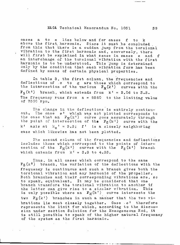
cases a to e lies below and for cases f to kabove the first. harmonic. Since it must ,be concludedfrom this that there is a sudden jump from the torsionalvibration to the first harmonic and, conversely, therewill first be explained in what sense in cases e and fan interchange, ,of the torsional “vibration with the firstharmonic is to be understood. This ‘jump is determinedonly by the condition that ,each vibration form has beendefined by means of certain physical properties.
In table 3, the first column, the frequencies anddeflections of c tO g are those which correspond tothe, int~rsection of the various FM(kt) curves with the
F@q branch , which extends from k! = 2.06 to 3.3.
The fl-equency runs from n = 5580 to the limiting valueof 7300 rpm.
The change in the deflections is entirely continu-ous ● The case e I which was not plotted cor~esponds tothe case that an F~(kl) ‘curve Roes accurately throughthe pojnt of intersection of the Y.S(k I) curve with the~t axis at ~ef =3.3; f’ is a closely neighboring
case which likewise has not been plotted.
The second column of the frequencies and deflectionsincludes those which correspond to the points of inter—section of the FIx(kl) curves with the l?~(kl) branchwhich e~teilds froi~ k~ = 3.3 to 4.33.
Thus , in all cases which correspond to the sameFs (1C?) branch , the variation of the deflections with the
frequency is continuous and such a branch gives both thetorsional vibration and any harmonic of the propeller.Both branches and their corresponding vibrations are, soto speak, equivalent , It may be considered that one%ranch transfers the torsional vibration to another ifthe latter can give rise to a siallar vibration. Thisis only possible where an F1t(k’) curve intersects the
two I?S(kl) branches in such a man”ner that the two vi–
brations +ie most closely together. Case .ei thereforerepresents t’he limit for which, according to the discus-sion under section Soluti’on for the Homogeneous Rod, itis still possible to speak of the higher natural frequencyof the system as the first harmonic.
,.
~... -. .,,, ,,,,,, “, . .“,, .
..—. —
40 NA,CA Technical lIemoran.dum No. 1051. .
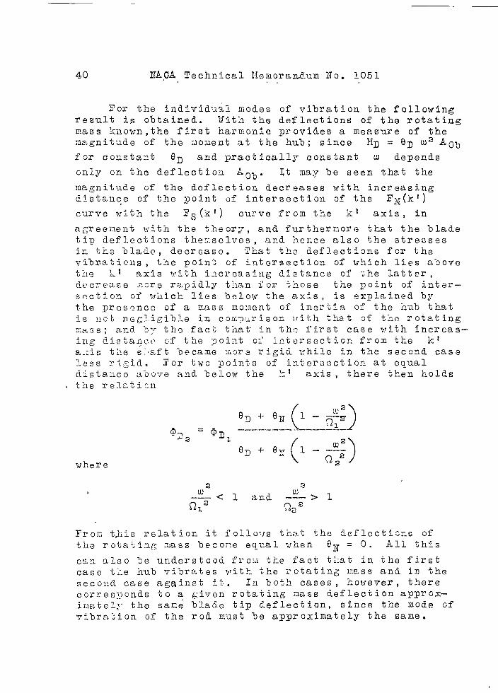
Tor tlze individual modes cf vi%ration the followingresult is obtained. With the deflections of the rotatingmass kilown,.the first harmonic yrovides a measure of theme,gnitude of the ~ilouenta,t the hub; since ~iD = 8D 0.)2AO~
fOr COilSta::t 9~ and practically constant u depends
Grlly on the deflectiO~~-A0“0“ It may ‘De seen that tile
magnitude of the deflection decreases with increasingdistailce of the point of intersection of the F;\~(k’)
cymve ~~iih the Fs(k’) curve from the k’ axis , in
agreel:~ent with the theory, and furtherr,ore that the “oladetip deflections themselves, and he~ce also the stressesin the “clade, decrease. That the deflections for tilevj.~raticus , the point of ip.tersection of which lies above
I-ftile .. axis with increasing distailce of ‘~b-elatter ,d~~cye:],se,“1-~cTe ra-L~idly than for these the point of int.er–section of vlilichlies below the axis, is explained bythe prcsencc of a mass mo:flentof inertia of the hub thatis Dch negligible in corl-p~~risonviih that of the rotatingrlass; a,nd ‘D:rthe fact tilat in the first case with increas–ing distaqc.t~ of the ;30iilt01’ intersection from the :kI
a-:is the s:,aft became ~.ore rigid while in the second caseless ri~id, i’or two ~oints of irLterssction at equald.istaizce a-oove and “celow the ;-1-I axis , there then holdsthe rel-~,ticn
2w
.—— <
c?~z1 and
2w-—— >1
(-)-2G
y~ojy ~,his relation it folloTJs that the def’lectisns of+’-IProtatia~dL-. mass becore eqv-al w:hen ON = O. All this
can :JLSO be up-de~.stoo(j-fr~lfithe fact tl:at in the first’
case tke hub vitirates with tl?e i-otating mss and in the~ecolld case ag~illSt it. In both cases, however, thereco~res?pcnds %0 a ~;ivellrotating ,nass deflection approx-iio~:telj-the sari; bla~e tip deflection, cince the mode ofvibrabion of the rod m.usi he approximately the same.

lTACA Technical Memorandum, No.’lO5l . 41
In the torsional vibration the deflections can no ,.. - longer serve a=.a...measure for. the moment, because the
frequency continuously changes. Consideration of the ~ratio of the blade tip deflection to that: of the rotating -mass shows, however, that on approaching the first har~monic the latter comes more, into evidenae so that the ~torsional vibration in case e’ corresponds approximately .to the first harmonic. in case fl and conversely. . ,
Another important fact obtained from the experimentis that for propellers of the Ju PAK type where the fun–damental vibration of the blades about the chord 1 is .lower than the first harmonic about the small axis the .blade vibrations set up about the small axis are rela–tively large if the torsional vibration lies below thefirst harmonic and small if it lies above the latter.
Setting up the same table for an untwisted prismaticrod, the same general results are obtained except for thecondition that the rod, with regard to the shove–menti,onedproperty of the “propeller, behave~ in just the reversemanner prorided that for the rod under consideration; thefundamenta~ vibration about the c’herd likewise lies lowerthan the first harnionic about the small axis. I?ur’therinvestigations on this question revealed a fundamentaldifference between rod and propeller blade. On observingthe direction of vibration of the propeller tips it was -found that as the torsional vibration approaches the firstharmonic the direction rotates in both cases. and thatthis occurs in the rod in exactly the opposite sense tothat in the propeller blade. l?igure 45 shows this turningof the vibration direction of the propeller blade tip.Trom this direction of vibration the corresponding vibra–tion modes of. the blade can be immediately derived. !l?hisis shown in figure 46. I?or each case the vibration modeabout the small axis (dotted) and that about the chord(continuous) are drawn as projections in the torsionalvibration or propeller disk plene.
In the case k!< 3.3 the vibration moment of thetwo vi%ratious has the same direction; for kl = 3.3there is practically no vibration about the chord; andfor .k! >.3i3 the.m.oments about the chord and small axis:net in opposite direction-s.
I?or the Prismatic untwisted rod the theory requires “a rotation of the direction of.vibration as shown in fig–ure 47. YOT the vibretion modes are obtained ffon %hese

42 NACA Technical Me-moranduni ITo. 1051
directions such that the co~ilPonents of their moments ~tthe b%ade roots in the torsional vibration plane have thecombined effect shown in figure 43, as was also o?3served.The same behavior is observed with a prismatic nonhorcoge-neous rod with constant thickae~s and width decreasingtoward the outer end (x= o) so that the p~rticularbehavior of the propeller blade should be determined bythe t~ist.. Further investi~ations will throw more l~<”rlton this, In the same way bet-h stroboscopic observatf O:lSof the vibration phenomenon and the observed ellipticpaths of each point of the ~roneller blade indicate aphase shift of the vibratio~ about the chord with res-oectto that about the small axis.
The difference in the !~agnitude of the deflectionsof the.rod and 31ade tips, respectively, about the ‘smallaxis for the torsioilal vibrp.tion above the first harmonicco~~gared to those below is thus explained. Quite ~ener–all”~, it is true that the motion aboq~t the sr.all axis inthe torsional vibration 5.s then relatively large if themoment of the vibration ~od.e a-oovt the small axis actsin the same sense as tkat abol~t the chord (see f’lg. 43).
The results here obtained now make it possible , inthe case of propellers cf the Ju P.4K tyoes, to state theapproximate direction in which. the resultant m~xim.um vibra–tion moment acts in the blade root during torsional vibra–t5.orlif the latter falls very closely above or “oelow thefirst harmonic. The thin arro”~s in fi~ure 48 give thedirection of the momeut .a-ooutboth axes for the vitrntionscorresponding to kl = 2.97 and 3.3 – that is Idll and M.ft.
Tti.equantitative solution of these problems and de—termination of the location of t?te maximum stress for thevarious vibration modes of tti.esyster~, \7h.tchrequiresmany tedious strain rneasuren.ents since the vibrati~ons dep-end to a large extent on the cross—section s’haue, *,7illform the s-~bject of a future investigation of the insti–tute.
For koth vibrations c~rrespocding to the valu5”k! =2.97 and 3.3, tke torsion~lly vibrating system. yi–”br,ates in resonance Il)=n. Fcr ~1 = 2.97’ t-he vi-Dra–tions about the smail axis are a minimum., and the funds–n.ental vibration of the blade is about the chord. Atk! =3.3 the vibration about the: chord is a minimumand the first harrzonic is alout thq small axis,

—
- NACA Technical Memorandum No. 1051 43
In order to show the difference between a flight,. propeller and a ri~id propeller, a heavy rigid, iro.n plate
of mor.nent of inertia r3L,= 64 kgcms2 was attached to th,e
shaft instead of the propeller and the deflection of therotating mass was measured for e“qual resonance frequency.This means that instead of the propeller function anyother engiile function iiltersects so that the point ofintersection lies directly on the kf axi s. The valu’esoltained were
k’ AD AID v-—-----—-—-—— ---—. ——--- -———— -.--— --———— --—-- —.-
2.97 35 45 . 1.29
3.3 l(j 29 2.90__—e— -———— -. —.—- ———-——— .——-—-—
Aln is the deflection with the plate and V is the,.
ratio of the tvo deflections. Siilce in both cases thefrequency wos the same, V at the same time gives theratio of the moments in the shaft.
The above is an explanation of the fact that in thetorsiogram the deflections with the flight propeller aregenerally smaller than those with a rigid brake propeller,siilce the lowest natural frequency of the brake propellerlies higher than that of the torsional vibration system -
~<qllnthat is, . These cases are represented in the
6; 1“~s, ~M diagrams if the ~M function intersects the kl
axis to the left of the corresponding kl. value; forthe homogeneous rod kf = 1.875. Comparison of figures5 to 15 shows that the resonance frequencies so definedare practically independent of. the pitch angle. Theresultant falls practically in the torsional vibrationplane so that ‘on the entire brake propeller there. is nogreater moment than that computed from the to~siodiagram,‘oecause the Ys(k’ ) curves for a = O and 90 run prac-
tically the””same nithin the range considered. In thiscase ~f2(a=o) Itfh(a=su)o) and hence for any angle a
,–h’
~!It:=o)‘Os 2 a + M(a==oo) $in2 a ‘UD= constant
Translation by S. Reiss,National Advisory Committeefor Aeronautics.
44 NACA Technical Memorandum No. 1051
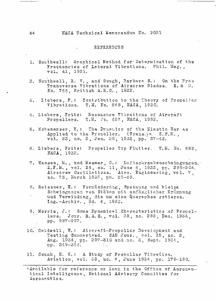
1. Southwell: Graphical Method for’ i)eterminatioc of theFrequencies of Lateral Vi’orations. Phil. I\fag,,vol. 41, 1921.
2. Southwell, R. V’., and Gough, 3arbara S. : On the TreeTransverse Vibrations of Airscrew Blades. E,& ~:.
ITo. 765, British A.R.C. , 1922.
s. I,iebers, F.: Contribution to the Theory of PropellerVibrations. T.M. NO. 568, ITACA, 1S30.
A.. ~iebers, Fritz: Resoriance Vibrations of Aircraft.Propellers. T*M. i’o, 55’7, NACA, 1932.
5. Iiohenemser, K. : The Dvli~~,i~~ of the Elastic Bar asApplied to the Proneller. (Trans.)~ Z.F.N. ,vol. 23, no. 2, Jan. 28? 1932, pp. 37–43.
6. Liebers, I’ritz: Propeller Tip Flutter. T.M, ~to. 683,NACA, 1932.
7, Hansen, Ii,, and Mesmer, C-.: Luftsc?.raubensc’hmingungen,Z.F,M. , vol. 24, no. 11, June 6, 1533, PD. 298–304.Airscrew Oscillations. Airc. Engineering, vol. 7 ,no. 73, Uarch 1935, pv. 55–69.
8. Reissner, H. : I’orr.;,nderiing, Spannung und kleirieSchwingurigen VOQ $t~ben mit anfb.nglicher Kr~lrnm-ungund Verwindung, die urn eine Querachse rotieren.Ing.–Archiv. , Ed, 4, 193:..,
.. Morris, J.:o Some Dynamic~l, Ch~racteri sties ,of Propel–..lers. Jo-~r. R,A.S. , TTol. 38, no. 288, Dec. 1934,
~ PP* 987–99’7.
10;. Caldwell, W,: Aircr~ft-Propeller Develop~Jent andTesting Summarized. SAE Jour. , vol. 35, no. .2,Aug. 1934 p~. 297–310 and fiO. 3, Sept. 19Z4,p-p. 349–3;3; ,.
11. Couch, II. H. : A Study of Propeller Vi-cra%ion.Aviation, vol. 53, ho. 6, June 19.34, -pD. 179–180. .,
.—*Available for reference or loan in the Office of Aeronau-tical Intelligence, lTational Advisory Comnittee forAeronautics.

.. . . .-., -.7 ~.,’ ,.”... . ..-
NACA Technical .Mem.?randum. i~o. .1051 45:, ..
.. . . . .. . . ., .. ,.12, Lie bers, Y. ;.”Ana~ysis of the Three Lowest Bending
Frequencies of a Rotating Propeller. T.M. No. 783,~ NACA, 1936. ” ‘
13, Riz J P.: The Resonance Method of Determination of theNatural Frequency of Airsc.rew Blades. CAHI No. 242,1935. (Russian) .
1A. Theodorsen~ T. : Propeller Vibrations and the Effectof the Centrifugal Yorce. T.N. ITo. 516, ifACA, 1935,
15, Ramherg, Walter, Yallif$” Paul” S. , and West, Mack J, :A iiethod for Determining Stresses in a I?onrotatingPropeller Blade Vibra”tin& ‘rith a Natural Frequency.Nat . 3ur. of Standards Jour. Re.s., vol. 14, no. 2.,Feb. 1935, pp. 189–215,
lEi. Xu nk , Max M. : Propeller Forces. And a Suggested Cor-rection I?actor for Use in Their Calculation. AeroDigest, vol. 25, no. 5, May 1935, pp. 22, 24, 26,
1’7.L~renbaum. K. : Schvingungen des Systems ICurbelwelle–Luftscht-aube. Luf’tfahrtforschung, Bd. 13, Lfg. 10,Oct. 32, 1936, pp. 346-E56 and DVL Jahrb. 1937,D-D. 11’ 117-12?. Vibration of Crankshaft Propeller>~~stems. S.4E Jour. , vol. 39, no, 6, Dec. 19.36,pp s 459–479.
18. Couch H. II.: Propeller-Crankshaft Vibration Pro%lems.Trans. Mech. Engineers, vol. 58, no. 4, Apr. 1936,pp. 215–21.
19. Carter, .B. C,: The Vibration of Airscrew Blades withParticular Reference to ‘Their Response to HarmonicTorque Impulses in the Drive. R. &M, NO. 1758,British, A,R.C. , 1937.
.
. .
__ ———.- ..----- .-—

!!.!. ! ,, ,, ,,,, , , ,,, ,, ,, , , , ■u, ., ,, ,, ,., ,. ,,
46 NACA Technical Memorandum No. 1051 .
WITH DIFEERINT PROPELLERS ..
‘Propeller ‘ 1’ nl ,
1.
‘3L .
~.
4.
5*
6.
7“
8.
Schwa.rZ, adjustable j-blade, for’He 111; .D=330~ImII . . . . . I,3000 ‘
Schwarz, adjustable for SAM 323He 50; D = 3650ma . . . ...12500
Schwarz, adjustable club for SAM 3233=2160 mm . . . . . . ... . 480a
Sch~fer As-10; D = 2500 mm . . . .’. 2gb0
Ju PC . . . . . ... . ... . . . 2000
J-blade VIM adjustable dural forDo 17 . . . . . . .. ...’... 2700 :
2-bl’ade~v~ adjusta”Dl e . . . . . . i 2200
Iieine,wood; D = 2270mI , . . . . ~ 3060
T%BLE 2”’””
‘-’k15.0
: 9*33,> 4.93”: 4.93
“ 4.93; 4.93g ti.93h 3.3i 2.4k 2.4
02 $-z
nj, ooo209,000
“345,000417,000528,000720,0G0
1,130,0001,690,0002,320,0003,530,000
,%’‘6~oo
6300
6600
6600
“ ‘6400.
6700
.5600
63001
. .T!@Lx 3
e’ ]7100
----1--
n2
7600
5700
9000
9300
5500
8%00
6900
9500
=-l-=57/14 730054/13 -7300
I
45/lb36/2227/?7’23/3016/32
I I
f’ 7170I10/287230 6/207300 3/17
f 7300 2/157300 1/10
g 7300!0.5/9I
73007300jjoo73007300
7y3075007700
7930gqqo
9600
“Aob
1/101.3/132/14
2.5/164.~/lg7/19
AD
14/17~3/912/5
11/29/0.7
6/0.6

~–’-””-
. ,,
‘NACATechnical Memorandum No. 1051 Figs. 1,3,4,28,29,30,31,34,35
●
:%c!
&“.I-l,q
+1 ‘k. .5-+1rn.Go m-a-d m .I-l.@ In~. rnal a)9Adg @h
a(no
100!
Figure l.= Torsional vibration character-istic of a 4-cylinder in-line”-
engine as measured on test stand and in
~D~’L 41 f1ig:’:&L?3’Figure 3.- Equiv- VFigure 4.- Figure ~8.- Blade length ?for the
alent Equivalent experimental determin-system of radial system of radial ation of the propeller functionengine with rig- engine with elas- Fm(ki).id propeller. ti~ propeller.
“
3
2
1
0
-3
1— k 1;1 \\\ ,, , -—- -—.——__
L—l__L__uJi!’ II , LL-_i+ L____ IabcTe f’ ghl k
1 2 3Figure 29.- Determination
functionl:f ajustable propeller.
q
- i;;B
Shaft--l
4- 5 K!
of the F~(kl)Ju PAK : ad-
Figure 30.- Rotating masssystem,
Figure 31.- Equivalentsystem of in-
line engine with propellerhub.
\
)- L-–-D “--%! l-----BRotating
~&p~mass----- / [ )Yigure 34.- Vibraticm moment Fundamental First hur- Second har-
in the propeller vibration moqic monicblade. Figure 35.- Natural vibration modes
of the propeller onengine.

NACA Technical Memorandum ?To.1051 Figs. 2,16,26,27,44
Figure 2.- Exciter apparatusfor coupling vi-
brations of crankshaft-pro-peller system.
Figure 16.- Vibration testswith prismatic
homogeneous rod for varyingpitch setting.
Figure 26.- Vibration testswith a non-
homogeneous rod.
Figure 27.- Exciter apparatusfor propeller vi-
'orations with variable torsion-al elasticity and rotating massto approach the actual engineconditions.
Figure 44.- Failure due toflexural vicra-
tions of a light metal pro-peller at the blade root.

lr-NACA Technical Memorandum No. 1051 Figs. 5,6,7,8,9
Figure 5.- Rod function of& prismatic homo-geneous rod. r = O; ~= C).
Figure 6.- Rod function ofprismatic homo-
geneous rod. r = 0.12;tf=o. ●
4, 1 I 1 I I 1 1 I I 1
Figure 7.- Rod function& of prismatichomogeneous rod. r = 0.22;d= o.
Fi&~zre 8.- Rod function ofprismatic homo-
gei~eous rod. r = O; d= O;~h/~f~ = 15. *
A , , 1 11 I II 1 I
Figure 9.- Rod function+ of prismatichomogeneous rod. r = 0;0!= 15°; Jh/Jf~ = 15.
F-f
I f b i I1 ,
I-z 1 I
-3 1 I I I

,
NACL Teclinical Memorandum No. lC)S] Figs. 10,11,12,13,14
f
8
-1
-1
-J
t II 1 1 1 I 1 1 1 1 1 1 1 1
I 11-1 I
lull
Figure 10.- FLo.ifunction cf* prisxa:ic homo-geneous rod. r = 0; a= 30°;Jh/JfZ = 16.
Figure 11.- Rod function ofprismatic horflo-
~od. r = O; cl= 45°;:;:::;s=: 16,
w
,3
IT’—... 1 I I
J 1i II !1’1 i
-i2 i
f
#
S6 7
-? II
-2 I
1
1
I ~-3 t
Figure 12.- Rod function of\ prismatic honio-Reneous rod. r = 0: ~= 60°:ih/Jfz = 16.
Figure 13.- ?ho~ ~U~ctiOn ofprismatic homo-
geneous rod. r = O; ci= 90°3Jh/JfZ = 16.
*
J
&
z—- i
fFigure 14.- Rod function of
e— prismatic homo-geneous rod. r = 0.11 ;
-7 60°; Jh/Jf ~ = 16.-z
/-1 I II 1 I
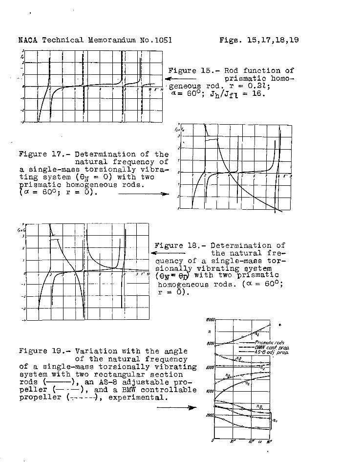
,
NACA Technical Memorandum No.1O51 Figs . 15,17,18,19
3 1 r
&I
z i I1I Figure 15.-7 Rod function ofI. . 4
# 1-&.— As JI
prismatic homo-
+ ~5 ; 7 89“ ~~n geneous rod. r = 0.21;
u = 60°; J@f~ = 16.-r
-2 I I ~I
-3 II I*
&uk3
----1
,?
Figure 17.- Determination of thenatural frequency of ‘ 1
a single-mass torsionally vibra- , Ating system (Cll{= O) with two ? 2 56 7 dK’3
?
rismati.c homogeneous rods. ? L
a= 1300; T= 0). > ~I/
3 A \L
9, I
&~3 -
I2 i Figure 18.-
\ 1 Determination of* the natural fre-1
1 1 \ J/ quency of a single-mass toT-) I
0sionall~ vibrating system-
? 2 r + 567 8‘K” 0 (eN= @ With two pris~atlc
-7
I ‘ \l
homogeneous rods. (~= 60°;r = o).-z
/-3
[-*L Wwu,
J~ ●8is #’-Fn
.9=”z.?Om/. a-1‘—Prm7w+lc roab
Figure 19.- ----L34tW conf popVariation with the angle L ‘-—A S-8 OC/--”prop.
of the natural frequencyof a single-mass torsionally vibrating 1
system with two rectangular sectionrods ( ), an AS-8 adjustable pro- ,,-peller (—-— ), and a BMW centrollable woo
propeller (=-----), experimental.h.: ‘“b W,
----m( ----●,
k >
u’ IX7” L& Lx@
.

●
~ACA Technical Memorandum No.1O5I Figs. 2C,21,22,23,24
Figure 20.- Comparison ofthree different
engine functions ( ~ = 600,r = O, Jh/Jfz = 16).
Figure 21.- Comparison of threedifferent engine
so functions ( ~= 60°, r = O,p~cma z— Jh/Jf~ = 81) .ho
a Figure 22.- Variation of ~(x)< over the length ofan AS-8 Elektron adjustable
?0— propeller (I) and an I-W8 u-Elektron adjustable propeller
o w 42 4J 40 05 UC 47 af usy. (II) (diameter 2.10 and 2.30 m).
m-!rl@)m’
Figure 23.- Variation of Jfz(x)wover the length of
an AS-8 Elektron adjustable mpropeller (I) and an HM 8 u- *
Zlektron adjustable propeller#
(II) (diameter 2.10 and 2.30 um) . /
o
.
w
w
m
aQ
o
Figure 24.- Variation of Jh(x)over the length of
an AS-8 adjustable Elektronpropeller /)I anda HM8u-Elektron adjustable propeller(II) (diameter 2.10 and 2.30m) .
e

—,- —
NACA Technical iLemorandum No. 1051
? I 1~ ,1 I I3-
I I1 I I
I/ 1r, 1
Io 1
f 2-r-
-2/
-3 kII / I I II
Figs. 25,32,33,36
Figure 25.- Rod function< for the fun-damental vibro,tion of theprismatic non-homogeneousrod (p =I;q= l)r=O;d. o.
Figu~e 36.- ilecre.asein the mom:ntby th~ vibratien abc,ut
tlhe chord.
-—
.- ------ .-.. ---

.
NACA Technical Memorandum No.1O5I Figs. 37,38,39,40,~*l
QPtx#
Figure 37.- Torsional vi-bration dis-
placement of the rotatingmass as a function of theangle ct.
Rod
Figure 38.- Dependence of theangular displace-
ment of the hub on the angle ~.
—.— . Figure 39.- Dependence of
‘=. iE=i2ia-the rotatingmass displacement @D on-the angle d for a rectang-ular iron rod for the fun-damental vibration, tor-sional vikration, and firstharmonic, experimental.
Figure 40.- Dependence ofthe rotating
mass deflection @D on theangle ~ for an AS-8 Elek- ‘:=. “’ltron adjustable ~ro~eller Fund. men AI vibrof).n Tor.,omu/ “,bre f ;0 ,-7
for the”fund.amental” vi-bration, torsional vibrat-ion, and first harmonic,experimental. \
Figure 41.- Dependence of< the rotatingmass deflection @D on theangle d for a BMW Elek-tron controllable propellerfor the fundamental vibra-tion, torsional vibration,first harmonic, secondharmonic, experimental.

.
NACA Technical l!emorai~dumNo.IC)5] Figs. 42,43,45,4ti,47,48
H,-h’’tia +ffnma -~ a. (a +.5)
n~-~n~; ME-*
Figure 42.- Resolution ofthe vibration
moment into t’ne“momentsabout the two principalaxes of the cross section.
Figure 43.- Dependence of theratios ltin/YQand
~f~/MD on k! for the prismatic
homog&eous rod, computed fora. 6(30, r = 0, Jh/Jfl = 16.
Figure 45.-43 ~
Direction of vibra-tion of the propeller
tip for various values of k!
K’<qFigure 46.- Mode of vibra-
K‘-~9 4’>+?,
/’ ~----
tion of pro- /’..\
~eller blade for various ‘\ /-_.’
~alues of kl.\
.+ ‘%Figureo”48r-”-Dlrecticsrrof the”maximum vibration
moment “at the propeller bladeroot for various torsional “vibrations.
~––-–-

.- —
———-— .._
llllylgigiiijl~mr~‘ *}”,“~,,;,:;,~~~~,..$.’” “,:!.— _:>,_k._~.
\.\
‘4