fit/jazz - honda parts direct · pdf filethis manual covers the repairs of a 2009 model-series...
TRANSCRIPT

SHOP MANUAL
Fit/JazzBODY REPAIR
2009

A Few Words About SafetyService InformationThe repair information contained in this manual isintended for use by qualified, professional technicians.Attempting repairs without the proper training, tools,and equipment could cause injury to you or others. Itcould also damage the vehicle or create an unsafecondition.
This manual describes the proper methods andprocedures for doing repairs. Some procedures requirethe use of specially designed tools and dedicatedequipment. Any person who intends to use areplacement part, repair procedure or a tool that is notrecommended by Honda, must determine the risks totheir personal safety and the safe operation of thevehicle.
If you need to replace a part, use Honda parts with thecorrect part number, or an equivalent part. We stronglyrecommend that you do not use replacement parts ofinferior quality.
FOR YOUR CUSTOMER 'S SAFETY
Proper repair is essential to the customer's safety andthe reliability of the vehicle. Any error or oversightwhile repairing a vehicle can result in faulty operation,damage to the vehicle, or injury to others.
Improper repairs can create an unsafe conditionthat can cause your customer or others to beseriously hurt or killed.Follow the procedures and precautions in thismanual and other service materials carefully.
FOR YOUR SAFETY
Because this manual is intended for the professionalservice technician, we do not provide warnings aboutmany basic shop safety practices (for example, hotpart-wear gloves). If you have not received shop safetytraining or do not feel confident about your knowledgeof safe repairing practices, we recommend that you donot attempt the procedures described in this manual.
Failure to properly follow instructions andprecautions can cause you to be seriously hurt orkilled.Follow the procedures and precautions in thismanual carefully.
Some of the most important general service safetyprecautions are given below. However, we cannot warnyou of every conceivable hazard that can arise in doingrepair procedures. Only you can decide whether or notyou should do a given task.
IMPORTANT SAFETY PRECAUTIONS
• Make sure you have a clear understanding of all basicshop safety practices and that you are wearingappropriate clothing and using safety equipment.When doing any repair task, be especially careful ofthe following:
Read all of the instructions before you begin, andmake sure you have the tools, the replacement orrepair parts, and the skills required to do the taskssafely and completely.Protect your eyes by using proper safety glasses,goggles, or face shields any time you hammer, drill,grind, or work around pressurized air or liquids andsprings or other stored-energy components. Ifthere is any doubt, put on eye protection.Use other protective wear when necessary, forexample, gloves or safety shoes. Handling hot orsharp parts can cause severe burns or cuts. Beforeyou grab something that looks like it can hurt you,stop and put on gloves.Protect yourself and others whenever you have thevehicle up in the air. Any time you raise the vehicle,either with a lift or a jack, make sure that it isalways securely supported. Use jack stands.Protect yourself by wearing an approved weldinghelmet, gloves, and safety shoes any time you arewelding. Protect yourself from burns from hotparts; allow the parts to cool before working in thatarea.Protect yourself from paints and harmful chemicalsby wearing an approved respirator, eye protection,and gloves whenever your are painting. Spraypaint only in an approved paint booth that is wellventilated.

How to Use This Manual
This manual covers the repairs of a 2009 model-series Fit/Jazz that has been involved in an accident, and itdescribes the work related to the replacement of damaged body parts.Please read through these instructions and familiarize yourself with them before actually using this manual.NOTE: Refer to the appropriate Fit/Jazz Shop Manual for specifications, wire harness locations, safety standsupport points, etc.Additionally, we have just completed and introduced the following manuals for your convenience. We stronglyrecommend you to refer to these manuals also before carrying out your job.
Body Repair Manual - Paint Basic P/N 62PRM30 for the outline of Paint Repair.Body Repair Manual - Body Basic P/N 62BRM30 for the outline of Body Repair.
Special Information
You CAN be KILLED or SERIOUSLY HURT if you don't follow instructions.
You CAN be HURT if you don' t follow instructions.
NOTE: Gives helpful information.
Detailed descriptions of standard workshop procedures , safety principles and service operations are not included.Please note that this manual does contain warnings and cautions against some specific service methods whichcould cause PERSONAL INJURY, damage a vehicle , or make it unsafe . Please understand that these warningscannot cover all conceivable ways in which service, whether or not recommended by Honda, might be done or ofthe possible hazardous consequences of each conceivable way, nor could Honda investigate all such ways.Anyone using service procedures or tools, whether or not recommended by Honda , must satisfy himselfthoroughly that neither personal safety or vehicle safety will be jeopardized.
All information contained in this manual is based on the latest product information available at the time of printing.We reserve the right to make changes at any time without notice. No part of this publication may be reproduced,stored in retrieval system, or transmitted, in any form by any means, electronic, mechanical, photocopying, recording,or otherwise, without the prior written permission of the publisher. This includes text, figures and tables.
HONDA MOTOR CO., LTD.Service Publication Office
First Edition 05/2008 124 pagesAll Rights Reserved

Reference
Symbols
Replacement
The welding symbols in the removal/installation havethese meanings.
X: 2-Plate spot welding®: 3-Plate spot welding®: 4-Plate spot weldingIS: MIG plug weldingM: MIG weldingL= Welding length Unit: mm (in.)( ): The number of welds
Body Dimensional Drawings
Body measuring dimensions show the distancebetween the forward or upper edge of positioningbosses and/or holes shown in the detail sketches.
Black dots: Measuring point
Black Dot
ForwardForward Forward
However, the measuring points in the frame repairchart are always the centers of the holes.
Rust Prevention
The sketch shows the areas where sealer is to beapplied.
0-: Sealing locations
WHEELHOUSEUPPER
DAMPER EXTENSIONHOUSING
DetailSketch

Sections with an * include SRS components;special caution is required when servicing.

General InformationSupplemental Restraint System (SRS) ....................... 1-2SRS Component Replacement/
Inspection After Deployment ................................... 1-4Battery Terminal Disconnection/
Reconnection ............................................................ 1-5Identification Number Locations ................................ 1-6Lift and Support Points ................................................ 1-7Body Specifications/Wheel Alignment ....................... 1-9Exterior Parts Removal/Installation ............................ 1-10Front Body Construction .............................................. 1-12Roof and Side Panel Construction .............................. 1-14Floor and Rear Body Construction .............................. 1-16Door and Bumper Reinforcement Beams .................. 1-18Zinc-plated Steel Plate Repair ..................................... 1-19High-tension Steel Sheet Framed Area ...................... 1-20Precautions for High-tension
Steel Parts Area Repair ............................................. 1-21Headlight Bracket Replacement .................................. 1-22

General Information
Supplemental Restraint System (SRS)
This model has an SRS which includes a driver's airbag in the steering wheel hub, a passenger's airbag in thedashboard above the glove box, the seat belt tensioners in the front seat belt retractors, the side airbags in the frontseat-backs, and the side curtain airbags in the sides of the roof. The SRS unit is separate from the airbag assembly andhas built-in sensors. The following precautions should be observed when doing sheet metal work, paint work, andrepair work around the locations of the SRS components.
• The SRS unit (including the safing sensor and the impact sensor) is located under the dashboard and the side impactsensors are located in each side sill and rear wheel arch. The front impact sensors are located behind the right andleft ends of the front bumper. Avoid any strong impact with a hammer or other tools when repairing the front sideframe, the lower part of the dashboard, the side sill, and rear wheel arch. Do not apply heat to these areas with atorch, etc.
• Take extra care when painting or doing body work in the area below the center pillar. Do not expose the seat beltretractor and tensioner to heat guns, welding, or spraying equipment.
• SRS electrical wiring harnesses and connectors are identified with yellow color coding. Take care when repairingthis area. Prevent damage to the harness.
• Do not apply heat of more than 100 °C (212 °F) when drying painted surfaces anywhere around the SRS componentslocations.
• If strong impact or high temperature need to be applied to the areas around the locations of SRS components,remove the components before performing the repair work.
• If any of the SRS related components are damaged or deformed, be sure to replace them.
NOTE: For after-deployment procedures, and removal and replacement of SRS related components, refer to the Fit/Jazz Shop Manual.
FRONT PASSENGER'SAIRBAG
LEFT SIDE AIRBAG
CABLE REEL
DRIVER 'S AIRBAG
FRONT PASSENGER'SSEAT SITTING SWITCH/SEAT CUSHION PAD
RHD model is shown, LHD model is similar.
DATA LINKCONNECTOR (DLC)
SRS UNIT
RIGHT SIDE SEAT BELT TENSIONER
1-2

LEFT SIDE IMPACT SENSOR(FIRST)
LEFT FRONTLEFT SIDE CURTAIN AIRBAG \ / IMPACT SENSOR
LEFT SIDE IMPACT SENSOR(SECOND)
RIGHT SIDECURTAIN AIRBAG
RIGHT FRONTIMPACT SENSOR
RIGHT SIDE IMPACT SENSOR(FIRST)
RIGHT SIDE IMPACT SENSOR(SECOND)
1-3

General Information
SRS Component Replacement/Inspection After Deployment
NOTE:• Before doing any SRS repairs, check the DTCs, refer
to the appropriate Fit/Jazz Shop Manual, for the lessobvious deployed components (seat belt tensioners,front impact sensors, side airbag sensors, etc.)
• Do not replace the OPDS unit unless it is physicallydamaged or a specific fault was found during DTCtroubleshooting in the appropriate Fit/Jazz ShopManual.
After a collision where the seat belt tensionersdeployed, replace these items:
• SRS unit• Seat belt tensioners• Front impact sensors
After a collision where a side curtain airbag hasdeployed, replace the items for the side(s) thatdeployed:
• SRS unit• Deployed side curtain airbag(s)• Seat belt tensioner(s)• Side impact sensor(s) (first)• Side impact sensor(s) (second)• Front pillar trim• Center pillar upper trim• Quarter pillar trim• Headliner• Front grab handle• Rear grab handle• All related trim clips• Sunvisor
After a collision where the front airbag (s) deployed,replace these items:
• SRS unit• Deployed airbag(s)• Seat belt tensioners• Front impact sensors
After a collision where the side airbag(s) deployed,replace these items:
• SRS unit• Deployed side airbag(s)• Side impact sensor(s) (first)• Side impact sensor(s) (second)• Center pillar lower trim• Complete seat frame
After a moderate to severe side or rear collision, inspectfor any damage on the side curtain airbag or otherrelated components. Replace the components asneeded.
After a collision, where a side curtain airbag hasdeployed, replace all trim clips on that side, even if theyappear to be undamaged. Replace the clips on theseparts:
• Front pillar trim• Center pillar lower trim• Quarter pillar trim
During the repair process, inspect these areas:
• Inspect all the SRS wire harnesses. Replace, do notrepair, any damaged harnesses.
• Inspect the cable reel for heat damage. If there is anydamage, replace the cable reel.
After the vehicle is completely repaired, turn theignition switch to ON (II). If the SRS indicator comes onfor about 6 seconds and then goes off, the SRS is OK. Ifthe indicator does not function properly, use the HDS toread the DTC, refer to the appropriate Fit/Jazz ShopManual. If you cannot retrieve a code, do the SRSSymptom Troubleshooting in the appropriate Fit/JazzShop Manual.

Battery Terminal Disconnection/Reconnection
Disconnection
NOTE: Some system store data in memory is lost whenthe battery is disconnected. Do the followingprocedures before disconnecting the battery.
1. Make sure you have the anti-theft code(s) for theaudio and/or the navigation system (if equipped).
Reconnection
NOTE: Some system store data in memory is lost whenthe battery is disconnected. Do the followingprocedures to restore the systems back to normaloperation.
1. Clean the battery terminals.
NOTE: For some models, it maybe necessary towrite down the audio presets (AM and FM),because the audio unit does not retain the presetsafter the battery is disconnected.
2. Make sure the ignition switch is in LOCK (0).
3. Disconnect and isolate the negative cable (A) fromthe battery.
NOTE: Always disconnect the negative cable fromthe battery first.
4.. Disconnect the positive cable (B) from the battery.
2. Test the battery; refer to the appropriate Fit/JazzShop Manual.
3. Reconnect the positive cable (A) to the battery (B)first, then reconnect the negative cable (C) to thebattery.
NOTE: Always connect the positive cable to thebattery first.
2.9-5.9 N•mD", (0.3-0.6 kgf•m, 2.1-4.4 lbf•ft)
4. Apply multipurpose grease to the terminals toprevent corrosion.
5. Install the terminal cover (D).
6. Enter the anti-theft code(s) for the audio systemand/or the navigation system (if equipped).
7. Enter the audio presets (if applicable).
8. Set the clock (for vehicles without navigation).
1-5

General Information
Identification Number Locations
NOTE: The illustration shows the RHD model, LHDmodel is similar.
Vehicle IdentificationNumber (VIN) (Except KP model)
Front Left doorjamb
Vehicle IdentificationNumber (VIN)
Engine Number AutomaticTransmissionNumber
ManualTransmissionNumber
Vehicle Identification Number(VIN) (KP model)
1-6

Lift and Support Points
NOTE: If you are going to remove heavy components such as the suspension from the rear of the vehicle, first supportthe front of the vehicle with tall safety stands. When substantial weight is removed from the rear of the vehicle, thecenter of gravity can change causing the vehicle to tip forward on the lift.
Vehicle Lift
1. Position the hoist lift blocks (A) under the vehicle's front support points ( B) and rear support points (C).
2. Raise the lift a few inches, and rock the vehicle gently to be sure it is firmly supported.
3. Raise the lift to full height, and inspect the vehicle support lift points for solid contact with the lift blocks.
Safety Stands
To support the vehicle on safety stands, use the same support points (B and C) as for a vehicle lift. Always use safetystands when working on or under any vehicle that is supported only by a jack.
(cont'd)
1-7

General Information
Lift and Support Points (cont'd)
Floor Jack
1. When lifting the front of the vehicle, set the parking brake. When lifting the rear of the vehicle, put the shift lever inreverse for manual transmission, or in the P position for automatic transmission.
2. Block the wheels that are not being lifted.
3. Position the floor jack under the front jacking bracket (A) or rear jacking bracket (B). Center the jacking bracket onthe jack lift platform (C), and jack up the vehicle high enough to fit the safety stands under it.
4. Position the safety stands under the support points and adjust them so the vehicle is level.
5. Lower the vehicle onto the stands.

Body Specifications/Wheel Alignment
L13Z1 Engine models : 3,900 mm (153.5 in.)L15A7 Engine models : 3,920 mm (154.3 in.)
Front Wheel AlignmentCamber 0 ° 00'±1 °Caster 3 ° 20'±1 °Total toe 0±3 mm (0±0.12 in.)Wheel turning In 40 0 19 '±2 °
- ang le Out 33 ° 19'±1 ° (Reference)Unit: mm (in.)
Rear Wheel AlignmentCamber -1000+1 0
Total toe IN 2.5 mm±2.5 mm (0.10±0.10 in.)Unit: mm (in.)
1,475

General Information
Exterior Parts Removal/Installation
NOTE:• When removing the front fender, do not deform the upper portion (A) of the front fender.• When adjusting the door in or out, replace the mounting bolts (B) (90102-SFA-305).• Apply spot sealer to the mating surface, then install the front fender, the hood, the doors, the tailgate, and the hinges.• Before attaching the front fender, apply sealer to the mating surface of the front fender and front pillar outer panel.
OUTER PANEL
FRONT FENDER
FRONT FENDER
6 x 1.0 mm [SECTION: ZZ]18 N•m(1.8 kgf•m, 13 Ibf•ft)
FRONT DOOR
8x1.25 mmLOWER FRONT 29 N•m (3.0 kgf•m, 22 Ibf•ft)DOOR HINGE
(B) 8 x 1.25 mm
6 x 1.0 mm 29 N•m (3.0 kgf•m, 22 Ibf•ft)9.8 N•m ( 1.0 kgf•m, 7.2 Ibf•ft)

REAR DAMPERSTIFFENER
8x1.25mm22 N•m(2.2 kgf• m,16 Ibf•ft)
8x 1.25 mm22 N•m(2.2 kgf.m, 16 Ibf•ft)
REAR BUMPEREXTENSION(KQ model)
FRONT BUMPERBEAM
8x1.25mm22 N•m(2.2 kgf . m, 16 lbf•ft)

General Information
Front Body Construction
NOTE: Confirm that the sold as repair parts, refer to the appropriate Parts Catalog.
1-12

NOTE:• The parts marked with numbers are sold as repair parts.• The parts marked with letters are not sold separately and are shown only for reference.• [ ] : Thickness unit: mm (in.)• High-tension steel sheet: Tensioner strength 340 to 590 MPa.
No. Part Name Tensionerstrength (MPa)
Zinc-plating
® Hood Skin [0.6] (0.024) 340Frame [0 . 5] (0.020) 270
® Front Fender [0.8] (0.031) 270® Front Bulkhead Com p .
-1 Front Bulkhead Upper Frame Set [0 . 6] (0.024) 270-2 Front Bulkhead Side Sta y Set [0.6] (0.024) 270-3 Front Bulkhead Lower Cross -member Set [0.6] (0.024) 270-4 Front Bulkhead Lower Cross -member Plate [0.6] (0.024) 270
® Front Wheelhouse U pper Member [0.7] (0.028) 590® Front Dam per Housin g Com p .
a: Front Damper Housing [0.8] (0.031) 270 0b: Front Damper Base [2 . 0] (0.079) 270
-1 L. side: Wheelhouse Sub Set [0.8] (0.031) 270R. side: Wheelhouse Gusset [0.8] (0.031) 270
-2 Front Dumper Extension [0.8] (0.031) 590-3 Front Wheelhouse Lower Extension Set
c: Wheelhouse Lower Member [0.8] (0.031) 590d: Wheelhouse Lower Extension [0.8] (0.031) 590
© Front Side Frame Com p .a: Front Side Frame [1 . 8] (0.071)/
Back late, front [1.4] (0.055 )/ Rear [ 1.6] (0.063)590
b: Side Frame Extension [2.0] (0.079) 590c: Side Cross-member [1.8] (0.071) 440 0d: Outri gg er [1.2] (0 .047) 440 0e: Inside Sill Front Extension [ 1.6] (0.063) 590
-1 Bum per Extension Bracket [ 1.8] (0.031) 590-2 Side Frame Gusset Plate [1 . 6] (0.063) 590-3 Side Frame Gusset [0.8] (0.031) 590-4 Side Frame Su pport [1.0] (0.039) 270-5 Bumper Beam Extension Outer Bracket [1.6] (0.063) 590 0
® Dashboard Upper Comp.a: Dashboard U pper [0 .8] (0.031) 270b: Windshield Lower [0.7] (0.028) 270c: Dashboard Driver's side [2.0] (0.079) 590
Upper SideMember
Passenger 's side [1 . 2] (0.047) 590
® Dashboard Lower [0.9] (0.035)/Extension [ 1.4] (0.055) 440

General Information
Roof and Side Panel Construction
NOTE: Confirm that the sold as repair parts, refer to the appropriate Parts Catalog.
Front Rear

NOTE:• The parts marked with numbers are sold as repair parts.• The parts marked with letters are not sold separately and are shown only for reference.• [ ] : Thickness unit: mm (in.)• High-tension steel sheet : Tensioner strength 340 to 590 MPa.
No. Part Name Tensionerstrength (MPa)
Zinc-plating
D Roof Panel [0.65] (0 . 026) 270® Side Sill Outer Panel [0.65] (0 . 026) 270® Front Side Outer Panel Set [0 . 65] (0.026) 270® Rear Side Outer Panel Set 270® Front Pillar Upper Stiffener
Driver's side [1 .8] (0.071)/Passenger's side [ 1.0] (0.039)590
© Center Pillar Stiffener Seta: Roof Side Stiffener [0.9] (0.035) 590b: Center Pillar U pper Stiffener [1.6] (0.063) 590c: Center Pillar Lower Stiffener [0.9] (0.035) 590
OO Side Sill Stiffener Seta: Front Pillar Lower Stiffener
Driver's side [ 1.6] (0.063 )/Passen er 's side [1 .0] (0.039)590
b: Front Pillar Lower Corner Stiffener [ 1.4] (0.055) 440c: Side Sill Stiffener [ 1.6] (0.063) 590d: Side Sill Rear Stiffener [ 1.2] (0.047) 590
® Rear Pillar Gutter Comp.a: Rear Pillar Upper Gutter [ 1.0] (0.039) 270b: Rear Pillar Middle Gutter [0.65] (0 . 026) 270c: Rear Pillar Lower Gutter/Lower Gutter Extension [0.65] (0 . 026) 270d: Rear Pillar Gutter U pper Stiffener [0.7] (0.028) 270
® Front Pillar Inner Com p .a: Front Pillar Inner Upper 590"
Driver 's side [2.0] (0.079 )*'/Passen ger's side [1.0] (0.039)2 440`2b: Front Pillar Inner U pper Extension [1.0] (0.039) 270c: Front Pillar Inner Lower [ 1.4] (0.055) 590d: Front Jack-up Base [1.6] (0.063) 590e: Roof Side Rair
Driver 's side [1 . 4] (0.055 )/Passen ger's side [0 .8] (0.031)590
f: Roof Side Rear Rail [0.8] (0.031) 4409 Center Inner Pillar [0.9] (0.035) 590>> Rear Inner Panel Com p .
-1 Rear Inner Panel [0.6] (0.024) 270a: Side Sill Rear End Plate [1 . 0] (0.039) 270b: Rear Inner Stiffener [2 . 0] (0.079) 270c: Rear Inner Upper Panel [0.75] (0 . 030) 270
-2 Rear Wheelhouse [0.7] (0.028) 270Front Door Skin [0.7] (0.028) 270
Panel , Front [ 1.2] (0.047)/Rear [0.65](0.026)
270
13 Rear Door Skin [0.7] (0.028) 270Panel , Front [1 . 2] (0.047 )/Rear [0.65](0.026)
270
General Information
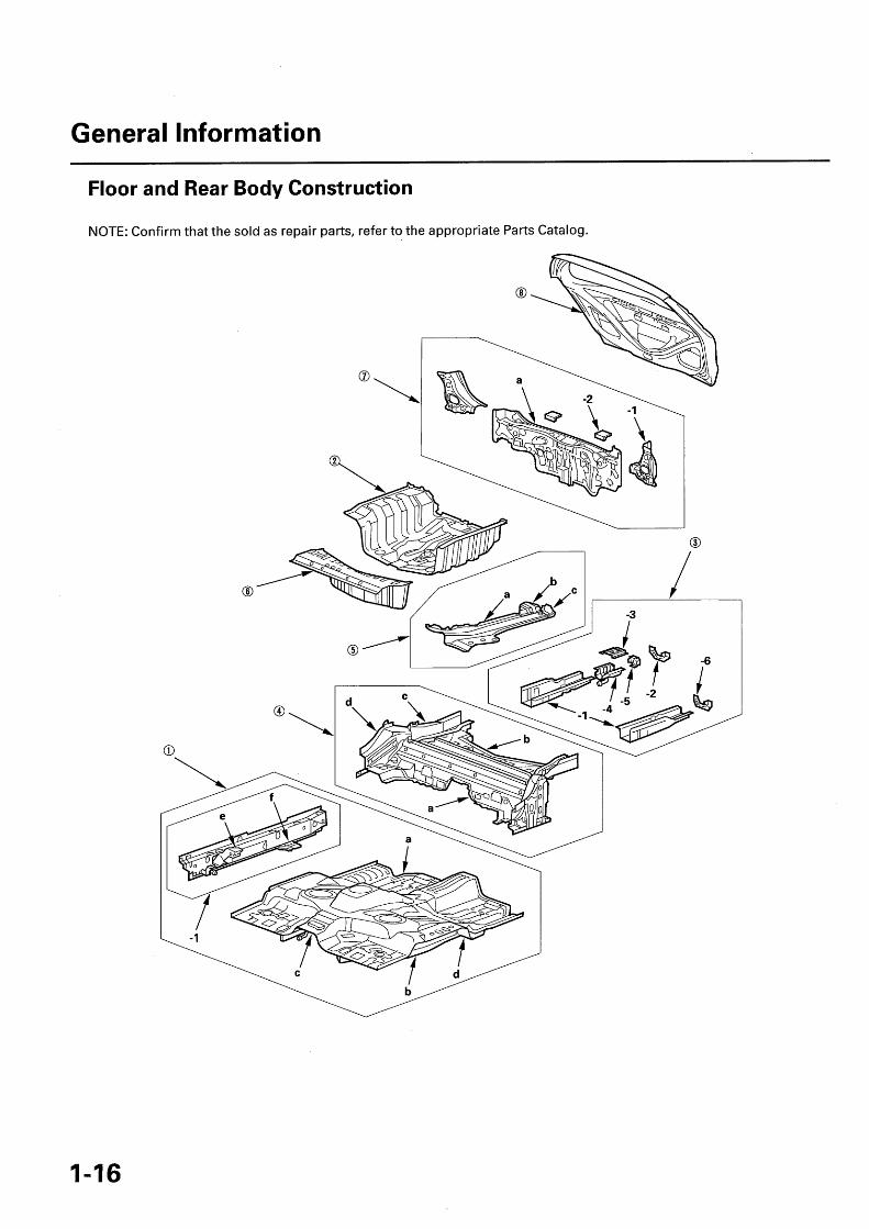
Floor and Rear Body Construction
NOTE: Confirm that the sold as repair parts, refer to the appropriate Parts Catalog.

NOTE:• The parts marked with numbers are sold as repair parts.• The parts marked with letters are not sold separately and are shown only for reference.• [ ] : Thickness unit: mm (in.)• High-tension steel sheet: Tensioner strength 340 to 590 MPa.
No. Part Name Tensionerstrength (MPa)
Zinc-plating
Front Floor Comp.a: Front Floor [0.6] (0.024) 270b: Front Floor Frame [1.8] (0.071) 590c: Floor Center Tunnel [0.7] (0.028) 270
Stiffener Cross -member [1.6] (0.063) 590d: Center Cross-member [ 1.6] (0.063) 590
-1 Front Inside Sill [1.4] (0 . 055) 590e: Front Seat Outer Bracket [ 1.8] (0.071) 590f: Inside Sill Gusset [ 1.6] (0.063) 590 0
OO Rear Floor Panel [0.6] (0.024) 270® Rear Frame Comp.
-1 Rear Frame B [1.0] (0.039) 440-2 Ri g ht Side Frame End Bulkhead [1.8] (0.071) 270-3 Rear Eye Bolt U pper Stiffener [1.2] (0.047) 270-4 Rear Eye Bolt Lower Stiffener [ 1.4] (0.055) 270-5 Rear Eye Bolt Stiffener [2.6] (0.10) 440-6 Left Side Frame End Bulkhead [ 1.2] (0.047) 270
® Middle Floor Cross - member Comp.a: Middle Floor Cross-member Stiffener [0.7] (0.028) 270b: Middle Seat Rear Cross -member [ 1.0] (0.039) 440c: Rear Frame A [1.2] (0 . 047) 590d: Side Sill Extension [ 1.4] (0.055) 590 0
O5 Rear Floor Side Panel Comp.a: Rear Floor Side [0.9] (0.035) 440b: Rear Floor Side Extension [0.5] (0.02) 270c: Rear Floor Side Gusset [ 1.2] (0.047) 270
® Rear Floor Extension [0.6] (0.024) 270 0Di Rear Panel Comp.
a: Rear Panel Panel [0.6] (0.024) 270U pper Stiffener [0.7] (0.028) 270
-1 Rear Panel Side Stiffener [ 1.0] (0.039) 270-2 Rear Bum per Face Stiffener [1 . 2] (0.047) 270
® Tailgate Skin [0 .65] (0.026) 270Frame [0.6] (0.024) 270
1-17

General Information
Door and Bumper Reinforcement Beams
The door and bumper reinforcement beams used on Fit/Jazz vehicles are made from a metal equivalent to high-strength steel.
If high-strength steel is heated, the strength of the steel will be reduced. If high-strength steel is damaged, for example.In an accident, and the door and bumper reinforcement beams are bent, the beams may crack when attempting tostraighten them. If a door beam is damaged, the whole door panel assembly should be replaced.
For this reason, the door and bumper reinforcement beams should NEVER be repaired; they should be replaced if theyare damaged.
REAR DOORFRONT BUMPER REINFORCEMENT BEAMREINFORCEMENT BEAM Do not repair.Do not repair.
FRONT DOORREINFORCEMENT BEAMDo not repair.

Zinc-plated Steel Plate Repair
The zinc-plated steel plate used in some panels of the Fit/Jazz require different repair techniques than ordinary steelplate. Refer to "Front Body Construction" (see page 1-12), "Roof and Side Panel Construction" (see page 1-14), "Floorand Rear Body Construction" (see page 1-16) for the location of the zinc-plated panels.
ZINC PLATING (5-6 microns)
STEEL PLATE
1. Before spot welding the zinc-plated steel plate, remove the paint from both sides of the flange to be welded. Applysealer to the flange after welding.
NOTE: Seal the sanded surfaces thoroughly to prevent rust.
2. The electric continuity properties for zinc-plated steel plates differ from ordinary steel plates. When spot welding,increase the current by 10 to 20 %, or increase the resistance welding time. Also increase the number of weldspots by 10 to 20 %.
NOTE: The MIG welding procedures for zinc-plated steel plates are similar to ordinary steel plates.
3. Before applying putty or body filler to the zinc-plated steel plates, sand the zinc plating thoroughly to promoteadhesion and prevent blistering.
NOTE: Use only epoxy-based putties and fillers on zinc-plated steel plates, and follow the manufacturer'sspecifications.
4. When doing paint work, protect the ground wire and the ground wire mounting hole threads with a bolt or a plug.

General Information
High-tension Steel Sheet Framed Area
The new high-tension steel sheet has greater tensioner strength than the conventional high-tension steel sheet.Although it's a thinner sheet, it maintains the same strength capacity as the previous thicker ones. Because themanufacturing press process has improved, the usage area has expanded. For this vehicle, the new high-tension steelsheet is used for its main frame and its cabin construction part to make the new model lightweight and to strengthenthe safety capacity of the high-crush absorption frame.
: New high-tension (590 MPa ) steel sheet
ROOF SIDE RAIL
CENTER INNER PILLAR
FRONT FLOOR CENTERCROSS-MEMBER
FRONT PILLARINNER LOWER
INSIDE SILLEXTENSION
GUIDE STAYREINFORCEMENT
REAR FRAME A
SIDE SILL STIFFENER
SIDE SILL EXTENSION
CENTER PILLAR STIFFENER
FRONT PILLAR UPPER STIFFENER
FRONT SIDE O\ \
FRONT PILLAR LOWER STIF FENERFRAME DASHBOARD UPPER SIDE MEMBER
FRONT FLOOR
ROOF SIDE STIFFENER
TUNNEL CROSS - \ WHEELHOUSE UPPER MEMBERMEMBER FRONT DAMPER EXTENSION
SIDE FRAME GUSSET/ WHEELHOUSE LOWER EXTENSION/GUSSET PLATE LOWER MEMBER

Precautions for High-tension Steel Parts Area Repair
• The new high-tension steel parts of the frame are allspot welded together. In order to disassemble, drill ahole in the sections that are spot welded togetherwith a very sharp spot weld bit.
• The new high-tension steel sheet is more rigid thanprevious steel sheets, making it difficult to strengthen.When an automobile's frame is partially constructedwith the new high-tension steel sheet, it should bestrengthened using an accurate frame straighteningsystem. Inspect the body and frame once the repair iscomplete for stress-related damage to the sectionsthat are not made from the new high-tension steel.
• High-tension steel has more memory than normalsteel, and it is necessary to monitor the bodydimensions closely during the straightening process.
• Spot welding is a acceptable for replacement parts aslong as the proper number of welds is used in therepair. For replacement part welding locations, referto "Replacement" in this manual. If spot weldingdoes not provide acceptable repairs, plug the weldsusing an MIG welder.
SPOT CUTTER GRINDINGMACHINE
1-21

General Information
Headlight Bracket Replacement
NOTE: Put on gloves to protect your hands.
When the Front bracket (A), the upper bracket (B) and/orthe lower bracket (C) of the headlight assembly (D) arebroken, it can be reinstalled using the repair brackets ifit meets this criteria;
• There is no damage to the headlight assembly.• The sealing of the headlight lens and headlight
housing is maintained.
Replacement
1. Remove the front bumper.
2. Remove the headlight assembly.
3. Cut or grind off the damaged front bracket (A), theupper bracket (B) and/or the lower bracket (C) sothat the bosses (D) of the headlight housing (E) areleft as shown. After removing the damaged bracket,finish the cut area with 400 grit sandpaper. Takecare not to scratch the headlight assembly.
Front Bracket
Upper Bracket
Lower Bracket

4. Install the front repair bracket (A), the upper repairbracket (B) and/or the lower repair bracket (C) onthe bosses of the headlight housing (D), then fastenit with the screws (E) provided with the repairbracket.
Front Repair Bracket
Upper Repair Bracket
Lower Repair Bracket
5. Reinstall the headlight assembly.
6. Reinstall the front bumper.
7. Adjust the headlights to local requirements.

Paint InformationPaint Safety Precautions .............................................. 2-2General .......................................................................... 2-3Color Chart Paint Specifications ................................. 2-4Features of Plastic Materials ....................................... 2-5Types and Materials of Exterior Plastic Parts ............ 2-7
Soft Chipping Guard Primer CoatGeneral Safety Precautions ......................................... 2-8Coating Area ................................................................. 2-9

Paint Information
Paint Safety Precautions
Most paints contain substances that are harmful ifinhaled or swallowed. Read the paint label beforeopening the container.
Observe the following precautions to maintain a safepainting work area.
• Wear an approved respirator and eye protectionwhen painting.
• Wear approved gloves and appropriate clothingwhen painting . Avoid contact with skin.
• Spray paint only in a well ventilated area.• Cover spilled paint with sand , or wipe it up at once.• If paint gets in your mouth or on your skin, rinse and
wash thoroughly with water . If paint gets in your eyes,flush with water and get prompt medical attention.
• After the painting work is finished, wash your faceand gargle with water.
• Paint is flammable. Store it in a safe place , and keep itaway from sparks, flames , or cigarettes.

General
The 3-coat-3-bake (3C•3B) paint finish gives the Fit/Jazz a deep gloss and stunning finish. This manual providesinformation on paint defects, repair, and refinishing. Throughout, the objective is to explain in a simple yetcomprehensive manner the basic items you should know about paint repairs. Select the correct material for the defectand repaint or refinish in the correct manner as described in this manual.
Basic Rules for Repairing a Paint Finish
To repair paint damage, always use the 2-part acrylic urethane paints designated; polish and bake each of the threecoats, as in production, to maintain the original film thickness, and to assure the same quality as the original finish.
Outline of factory painting process
Pretreatment Electrodepositionof primer
Features In Each Work Process
(Chipping Primer)Intermediate coat Top coat
Pretreatment and electrodepositionIn the pretreatment process, the entire body is degreased, cleaned, and coated with zinc phosphate by dipping.After the body has been cleaned with pure water, it is placed in an electrolytic bath of soluble primer (cationicelectrodeposition).This produces a thorough corrosion inhibiting coating on the inner surface and corners of the body, pillars, sills, andpanel joints.Chipping primer is then applied to the most susceptible areas (see page 2-9).
Intermediate coatThe intermediate coat is applied to the prepared surface to further protect against damage.
Top coatEnamel paint and either polyester or acrylic resin paint are used in the top coat for higher solidity, smoothness,brightness, and weather resistance.
Sectional view of paint coats
CLEAR COAT
ENAMEL COAT
3-COAT PEARL PAINT(White pearl)
CLEAR COAT
About120 microns(0.12 mm)
. PEARL BASE COAT
COLOR BASE COAT
UNDERCOAT(Electrodeposition)
BASE METAL
2-3
Paint Information
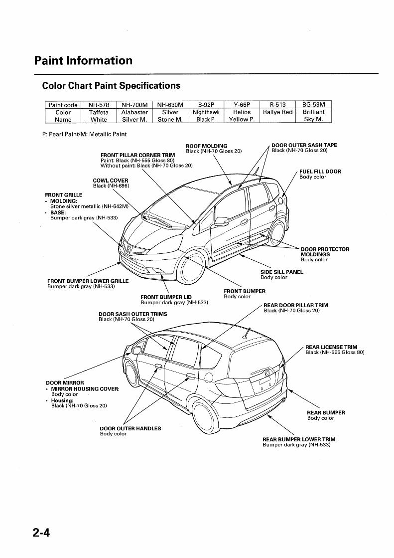
Color Chart Paint Specifications
P: Pearl Paint/M: Metallic Paint
FRONT GRILLE• MOLDING:
N H-578 NH-700M NH-630M B-92P Y-66P R-513 BG-53MTaffeta Alabaster Silver Nighthawk Helios Rallye Red BrilliantWhite Silver M. Stone M.
ROOF
Black P.
MOLDING
Yellow P. Sky
Black (NH-70 Gloss 20)
Without paint: Black (NH-70 Gloss 20)
FRONT PILLAR CORNER TRIMPaint: Black (NH-555 Gloss 80)
COWL COVERBlack (NH-696)
Stone silver metallic (NH-642M)• BASE:
Bumper dark gray (NH-533)
DOOR OUTER SASH TAPEBlack (NH-70 Gloss 20)
DOOR PROTECTORMOLDINGSBody color
FRONT BUMPER LOWER GRILLEBumper dark gray (NH-533)
FRONT BUMPER LIDBumper dark gray (NH-533)
DOOR SASH OUTER TRIMSBlack (NH-70 Gloss 20)
REAR DOOR PILLAR TRIMBlack (NH-70 Gloss 20)
REAR LICENSE TRIMBlack (NH-555 Gloss 80)
DOOR MIRROR• MIRROR HOUSING COVER:
Body color• Housing:
Black (NH-70 Gloss 20)REAR BUMPERBody color
PaintcodeColorName M.
DOOR OUTER HANDLESBody color
REAR BUMPER LOWER TRIMBumper dark gray (NH-533)

Features of Plastic Materials
• Check each of the plastic parts for solvent resistance and heat resistance before you do any repair work.• Select the repair material according to materials of the plastic parts.• Alcohol can be used for degreasing in small amounts, and for short periods of time. Do not soak.• Contact your paint and material supplier for other recommended cleaners for the type of plastic you are working on.
Standard Name Heat NoteSymbol Resistance
TemperatureOF (°C)
AAS Acrylonitrile acrylic styrene 176(80)
ABS Acrylonitrile butadiene styrene 176(80)
AES Acrylonitrile ethylene styrene 176(80)
A/EPDM/S Acrylonitrile/ethylene 176p ropy lene diene rubber/styrene (80)
ASA Acrylonitrile styrene acrylate 176(80)
CAB Cellulose acetate butylate 176(80)
ENAC Ethylene-vinyl acetate 176(80)
PA Polyamide 176 Battery acid (sulfuric acid) can damage(80) the material.
PBT Polybutylene terephtalate 320 Solvent can damage the material.(160)
PC Polycarbonate plastics 248 Brake fluid, wax, and grease remover(120) can damage the material.
PE Polyethylene 176 Solvent can damage the material.(80)
PF Phenol form aldehyde 176(80)
PMMA Polymethyl methacrylate 176 Wash remover off with water thoroughly.(80)
POM Polyoxymethylene polyacetal 212 Solvent can damage the material.(100)
PP Polypropylene 176 Solvent can damage the material.(80)
PPO Polyphenylene oxide 212(PPE) (100)
PS Polystyrene 140(60)
PUR Polyurethane 176(80)
(cont'd)
2-5

Paint Information
Features of Plastic Materials (cont'd)
Standard Name Heat NoteSymbol Resistance
TemperatureOF (°C)
PVC Polyvinyl chloride 176(80)
SAN Styrene acrylonitrile 176(80)
SMC Sheet molding compound 356 Solvent can damage the material.(180)
TPE Thermoplastic polyester 176 Wash remover off with water thoroughly.elastomer (80)
TPS Thermoplastic styrene 176 Wash remover off with water thoroughly.elastomer (80)
TPO Thermoplastic olefin/ 176 Wash remover off with water.thoroughly.elastomer (80)
TPU Thermoplastic/urethane/ 176 Wash remover off with water thoroughly.elastomer (80)
UP Polyester 230 Alkali can damage the material.(110)

Types and Materials of Exterior Plastic Parts
NOTE:• For the full plastic name, refer to the features of plastic materials (see page 2-5).• A standard symbol is stamped on the underside of each resin part to show the type of material used.
Example: ' HONDA ',>PP< ;
COWL COVER(PP)
FRONT GRILLE• MOLDING:
(ABS)• BASE:
(AES)
FRONT PILLAR CORNER TRIMPaint: (ABS)Without paint: (AES)
FRONT BUMPER LOWER GRILLE(PP)
DOOR MIRROR• MIRROR HOUSING COVER:
(ABS)• Housing:
(AAS)
FRONT BUMPER LID(PP)
DOOR OUTER HANDLES(PC)
SIDE SILL PANEL(PP)
FRONT BUMPER(PP)
REAR BUMPER LOWER TRIM(PP)
Soft Chipping Guard Primer Coat
General Safety Precautions
The removal of paint and undercoating by stone chipsimmediately exposes metal to the atmosphere, causingit to oxidize. The thickness of this oxidation increases ifthe process continues unchecked. The soft chippingguard primer protects against damage due to theimpact of such objects.
2. Air blowing/degreasing.Use alcohol, and wax and grease remover.
3. Protect from overspray.Use masking tape and paper to protect the relatedareas from overspray.
• The soft chipping guard primer coat is applied overthe E. D. (electorostatically deposited) primer. It isfollowed by guide coating and top coating.
• The soft chipping guard primer produces a smoothsurface when dry. It should be sprayed so thethickness of the protective film is 20 microns.
Sectional view of paint coats:Top coat
Intermediate coat
Chi pping g uard primerElectrodeposition
Base metal
• A soft chipping guard primer coat is then applied tothe most susceptible area (see page 2-9).
• Spray the primer surface (2-part urethane primersurfacer) on the soft chipping guard primer coatingareas when you replace parts using soft chippingguard primer coat.
Coating Procedures
• Wear goggles or safety glasses to prevent eyeinjury.
• Ventilate when spraying undercoat.
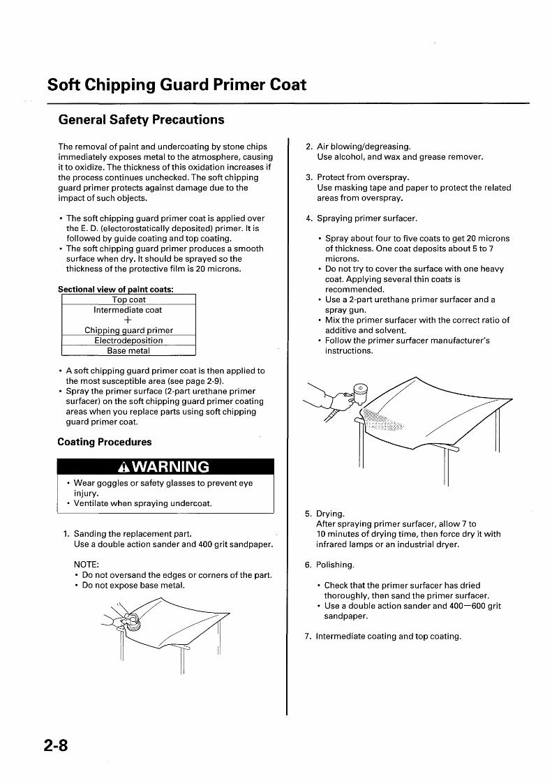
1. Sanding the replacement part.Use a double action sander and 400 grit sandpaper.
4. Spraying primer surfacer.
• Spray about four to five coats to get 20 micronsof thickness. One coat deposits about 5 to 7microns.
• Do not try to cover the surface with one heavycoat. Applying several thin coats isrecommended.
• Use a 2-part urethane primer surfacer and aspray gun.
• Mix the primer surfacer with the correct ratio ofadditive and solvent.
• Follow the primer surfacer manufacturer'sinstructions.
5. Drying.After spraying primer surfacer, allow 7 to10 minutes of drying time, then force dry it withinfrared lamps or an industrial dryer.
NOTE:• Do not oversand the edges or corners of the part.• Do not expose base metal.
6. Polishing.
• Check that the primer surfacer has driedthoroughly, then sand the primer surfacer.
• Use a double action sander and 400-600 gritsandpaper.
7. Intermediate coating and top coating.

Coating Area
indicates chipping guard primer coating area.
NOTE: Make sure to coat the flange on front and rear wheel arch.Unit: mm (in.)
HOOD SKIN
OUTER PANEL
[Section DD]
[Section CC]
REARINNERPANEL
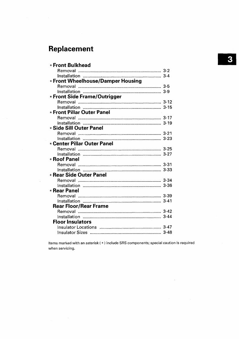
Replacement
* Front BulkheadRemoval ..................................................................... 3-2Installation ................................................................. 3-4
* Front Wheelhouse/Damper HousingRemoval ..................................................................... 3-5Installation ................................................................. 3-9
* Front Side Frame /OutriggerRemoval ..................................................................... 3-12Installation ................................................................. 3-15
* Front Pillar Outer PanelRemoval ................................................. .................. 3-17Installation ................................................................. 3-19
* Side Sill Outer PanelRemoval ..................................................................... 3-21Installation ................................................................. 3-23
* Center Pillar Outer PanelRemoval ..................................................................... 3-25Installation ................................................................. 3-27
* Roof PanelRemoval ..................................................................... 3-31Installation ................................................................. 3-33
* Rear Side Outer PanelRemoval ..................................................................... 3-34Installation ................................................................. 3-36
* Rear PanelRemoval ..................................................................... 3-39Installation ................................................................. 3-41
Rear Floor/Rear FrameRemoval ..................................................................... 3-42Installation ................................................................. 3-44
Floor InsulatorsInsulator Locations ................................................... 3-47Insulator Sizes ........................................................... 3-48
Items marked with an asterisk (*) include SRS components; special caution is required
when servicing.
Front Bulkhead
Removal
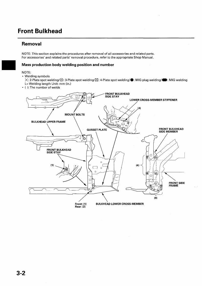
NOTE: This section explains the procedures after removal of all accessories and related parts.For accessories' and related parts' removal procedure, refer to the appropriate Shop Manual.
Mass production body welding position and number
NOTE:• Welding symbols
X: 2-Plate spot welding/®: 3-Plate spot welding/®: 4-Plate spot welding /40: MIG plug welding/M: MIG weldingL= Welding length Unit: mm (in.)
• ( ): The number of welds
FRONT SIDEFRAME
Front: (1)Rear: (2)
BULKHEAD LOWER CROSS -MEMBER
(9)

Construction
• Replace the front bulkhead side stay and the lower cross-member stiffener as an assembly.• If necessary, replace the bulkhead lower cross member.
FRONT BULKHEADUPPER FRAME
6 x 1.0 mm9.8 N•m (1.0 kgf.m, 7.2 Ibf•ft)
FRONT SIDE FRAME
BULKHEAD LOWERCROSS-MEMBER PLATE
BULKHEAD LOWER CROSS- MEMBERWHEELHOUSE LOWERMEMBER

Front Bulkhead
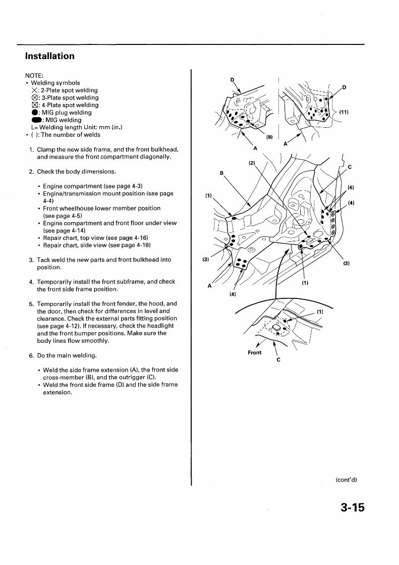
Installation
NOTE:• Welding symbols
X: 2-Plate spot welding®: 3-Plate spot weldingX: 4-Plate spot weldingI: MIG plug weldingW: MIG weldingL= Welding length Unit: mm (in.)
• ( ): The number of welds
1. Set the new bulkhead parts, and measure the frontcompartment diagonally.
2. Check the body dimensions.• Engine compartment (see page 4-3)• Front wheelhouse lower member position
(see page 4-5)• Engine compartment and front floor under view
(see page 4-14)• Repair chart, top view (see page 4-16)• Repair chart, side view (see page 4-18)
3. Tack weld the new parts into position.
4. Temporarily install the front fender, the hood, andthe door, then check for differences in level andclearance. Check the external parts fitting position(see page 4-12). If necessary, check the headlightand the front bumper positions. Make sure thebody lines flow smoothly.
5. Do the main welding.• Weld the front side frame (A) and the bulkhead
side stay (B).• Weld the bulkhead lower cross-member (C) to
the wheelhouse lower member (D), the bulkheadside stay, and the lower cross-member stiffener(E).
[VIEW: Z]
6. Install the bulkhead upper frame (A).

Front Wheelhouse/Damper Housing
Removal
NOTE: This section explains the procedures after removal of all accessories and related parts.For accessories' and related parts' removal procedure, refer to the appropriate Shop Manual.
Mass production body welding position and number [Wheelhouse upper member, lowermember , and damper extension]
NOTE:• Welding symbols
X: 2-Plate spot welding/®: 3-Plate spot welding/®: 4-Plate spot welding/ •: MIG plug welding/M: MIG weldingL= Welding length Unit: mm (in.)
• ( ): The number of welds
WHEELHOUSE UPPERMEMBER
(5) L=10 (0.4)
( 12)
DASHBOARD UPPERSIDE MEMBER
(2)
FRONT DAMPEREXTENSION
SIDE FRAME GUSSET
GUSSET PLATE
(cont'd)
3-5

Front Wheelhouse/Damper Housing
Removal (cont'd)
Mass production body welding position and number [Damper housing]
NOTE:• Welding symbols
X: 2-Plate spot welding/®: 3-Plate spot welding/®: 4-Plate spot welding/O: MIG plug welding/=: MIG weldingL= Welding length Unit: mm (in.)
• ( ): The number of welds
(1)
DASHBOARD (1)UPPER
DAMPER HOUSING
FRONT WHEELHOUSEGUSSET
Right side only
DAMPER HOUSING
DASHBOARD LOWER
(7) DAMPER HOUSING
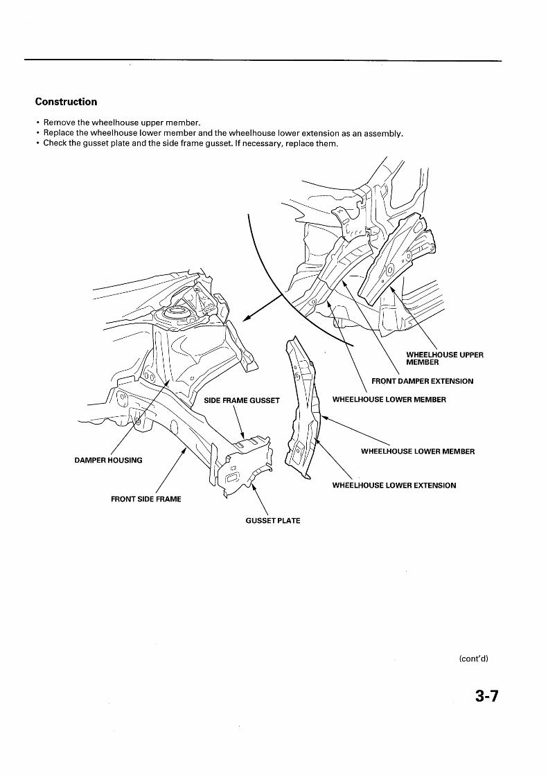
Construction
• Remove the wheelhouse upper member.• Replace the wheelhouse lower member and the wheelhouse lower extension as an assembly.• Check the gusset plate and the side frame gusset. If necessary, replace them.
GUSSET PLATE
(cont'd)
3-7

Front Wheelhouse/Damper Housing
Removal (cont'd)
Construction
• Check the front damper extension and the damper housing position for damage. If necessary, replace them.
NOTE: When replacing the front damper extension, drill the position shown in [DETAIL X] and [DETAIL Z] fromthe outside of the dashboard upper side member, and drill the two spot welded points (A) at the joint for the frontdamper extension and the damper housing with a 010 mm (0.4 in.) spot cutter.
• Drill the two spot welded points (B) at the damper housing and the dashboard upper from under side of the damperhousing.
DASHBOARD UPPERSIDE MEMBER
DAMPER HOUSING
FRONT DAMPEREXTENSION
DASHBOARD UPPER
DAMPER HOUSING / DASHBOARD UPPERSIDE MEMBER
FRONT DAMPEREXTENSION

Installation
NOTE:• Welding symbols
X: 2-Plate spot welding®: 3-Plate spot welding®: 4-Plate spot welding•: MIG plug welding•: MIG weldingL= Welding length Unit: mm (in.)
• ( ): The number of welds
1. Clamp the new damper housing, the front damperextension, the side frame gusset, the gusset plate,the wheelhouse lower extension, and the bulkhead,and measure the front compartment diagonally.
2. Check the body dimensions.
• Engine compartment (see page 4-3)• Engine/transmission mount position (see page
4-4)• Front wheelhouse lower member position
(see page 4-5)• Engine compartment and front floor under view
(see page 4-14)• Repair chart, top view (see page 4-16)• Repair chart, side view (see page 4-18)
3. Tack weld the new parts and the front bulkhead intoposition.
4. Temporarily install the front subframe, and checkthe front side frame position.
5. Temporarily install the front fender, the hood, andthe door, then check for differences in level andclearance. Check the external parts fitting position(see page 4-12). If necessary, check the headlightand the front bumper positions. Make sure thebody lines flow smoothly.
6. Do the main welding.Weld the damper housing (A), to the front sideframe (B), and the dashboard upper (C).
(2)
(9)
A
A
(cont'd)
3-9

Front Wheelhouse/Damper Housing
Installation (cont'd)
7. From the passenger's side, plug weld the holes inthe dashboard lower (A) and the damper housing(B).
1 (7)
8. Drill the holes for welding the new front damperextension (A). Weld the damper housing (B), thefront damper extension, and the dashboard upperside member (C).
(1)
(3)
9. Weld the damper housing (A) and wheelhousegusset (B) to the front damper extension (C). Weldthe front damper extension and the wheelhouselower extension (D).

10. Weld the side frame gusset (A) and the gusset plate(B) to the front side frame (C), and the wheelhouselower extension (D).
12. Weld the wheelhouse upper member (A). Whenreusing the wheelhouse upper member, weld itwith a MIG plug welding.
11. Weld the front bulkhead (see step 5 on page 3-4).

Front Side Frame /Outrigger
Removal
NOTE: This section explains the procedures after removal of all accessories and related parts.For accessories ' and related parts ' removal procedure, refer to the appropriate Shop Manual.
Mass production body welding position and number [Front side frame]
NOTE:• Welding symbols
X: 2-Plate spot welding/®: 3-Plate spot welding/®: 4-Plate spot welding/ •: MIG plug welding /M: MIG weldingL= Welding length Unit: mm (in.)
• ( ): The number of welds
Right side only Left side (10 ) DAMPER HOUSINGRight side (11)
WHEELHOUSELOWER MEMBER FRONT SIDE FRAME
(8)SIDE FRAMEEXTENSION
Driver 's side:3-Plate spot welding

Mass production body welding position and number [Outrigger and side frame extension]
NOTE:• Welding symbols
X: 2-Plate spot welding/®: 3-Plate spot welding/®: 4-Plate spot welding/ *: MIG plug welding/M: MIG weldingL= Welding length Unit: mm (in.)
• ( ): The number of welds
Bottom of the front floor.
FRONT SIDE \ FRONT FLOORCROSS -MEMBER
SIDE FRAME EXTENSION
FRONT FLOOR FRAME
SIDE FRAMEEXTENSION
OUTRIGGERDASHBOARDLOWER
OUTRIGGER
C (5)(4)
SIDE FRAME EXTENSION
A+B+C= ( 11) : Inside sill extension , tie down stiffener , and outrigger
(cont'd)
3-13

Front Side Frame/Outrigger
Removal (cont'd)
Construction
• When removing the front side frame, leave the side frame extension, the outrigger, and the front side cross-memberin place.
• Check the side frame extension, the outrigger, and the front side cross-member position for damage. If necessary,replace them as an assembly.
NOTE:• When removing the outrigger, leave the inside sill extension attached to the body side.• Carefully drill the three welded point (A) at the joints for the tie down stiffener and outrigger.
FLOOR FRAME
Installation
NOTE:• Welding symbols
X: 2-Plate spot welding®: 3-Plate spot weldingX: 4-Plate spot welding•: MIG plug weldingM: MIG weldingL= Welding length Unit: mm (in.)
• ( ): The number of welds
1. Clamp the new side frame, and the front bulkhead,and measure the front compartment diagonally.
2. Check the body dimensions.
• Engine compartment (see page 4-3)• Engine/transmission mount position (see page
4-4)• Front wheelhouse lower member position
(see page 4-5)• Engine compartment and front floor under view
(see page 4-14)• Repair chart, top view (see page 4-16)• Repair chart, side view (see page 4-18)
3. Tack weld the new parts and front bulkhead intoposition.
4. Temporarily install the front subframe, and checkthe front side frame position.
5. Temporarily install the front fender, the hood, andthe door, then check for differences in level andclearance. Check the external parts fitting position(see page 4-12). If necessary, check the headlightand the front bumper positions. Make sure thebody lines flow smoothly.
6. Do the main welding.
• Weld the side frame extension (A), the front sidecross-member (B), and the outrigger (C).
• Weld the front side frame (D) and the side frameextension.
(cont'd)
3-15

Front Side Frame/Outrigger
Installation (cont'd)
7. From the passenger 's side, plug weld the holes inthe dashboard lower (A), and the front floor (B).
(6)
9. Weld the wheelhouse, lower member (A), and theside frame gusset (B).
[Z)
(3)
Left side (11)Right side (10)
8. Weld the front side frame (A) to the damperhousing (B) and the front wheelhouse gusset (C).
Left side (10)Right side (11)
10. Weld the front bulkhead (see step 5 on page 3-4).

Front Pillar Outer Panel
Removal
NOTE: This section explains the procedures after removal of all accessories and related parts.For accessories' and related parts' removal procedure, refer to the appropriate Shop Manual.
Mass production body welding position and number [Outer panel and front pillar lowerstiffener]
NOTE:• Welding symbols
X: 2-Plate spot welding/®: 3-Plate spot welding/M: 4-Plate spot welding /s: MIG plug welding /M: MIG weldingL= Welding length Unit: mm (in.)
• ( ): The number of welds
Without outer panel
(3)
(2)FRONT PILLAR LOWERCORNER STIFFENER
SIDE SILL STIFFENER
(cont'd)
3-17

Front Pillar Outer Panel
Removal (cont'd)
Construction
• Remove the wheelhouse upper member (see page 3-5).• Cut and pry off the outer panel at the front pillar and side sill portion.
NOTE: Select the cutting positions in consideration of the front side outer panel repair part (see page 1-14).
• Replace the front pillar outer separator.• Check the front pillar lower stiffener position for damage. If necessary, replace it.• Replace the front pillar inner separator.
FRONT PILLARUPPER STIFFENER
FRONT PILLAR LOWERCORNER STIFFENER
FRONT PILLAR
INNER PANEL
OUTER PANEL
OUTER PANEL
OUTER PANEL
SIDE SILL STIFFENER
SIDE SILL STIFFENER OUTER SEPARATOR
Installation
NOTE:• Welding symbols
X: 2-Plate spot welding®: 3-Plate spot weldingX: 4-Plate spot welding•: MIG plug weldingW: MIG weldingL= Welding length Unit: mm (in.)
• ( ): The number of welds
1. Install the new front pillar inner separator (A) onthe front pillar lower corner stiffener (B).
NOTE: Apply the sealer (C) all the way around theseparator and inside the front pillar inner lower (D)without gaps.
2. Set the front pillar lower stiffener, and tack weld itinto position.
3. Rough -cut the front side outer panel repair part,clamp it to the body, and check the dimensions.
• Front wheelhouse lower member position(see page 4-5)
• Door hinge position (see page 4-6)• Windshield and door opening (see page 4-10).
4. Temporarily install the windshield, the door, thehood, and the front fender, then check fordifferences in level and clearance.Check the external parts fitting position (see page4-12). Make sure the body lines flow smoothly.
5. Trim the cut and joint areas of the outer panelrepair part as needed , and prepare the butt-weldingconnections.
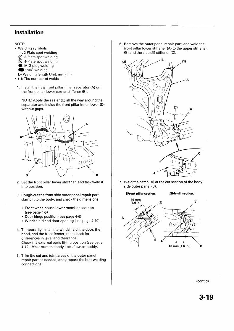
6. Remove the outer panel repair part, and weld thefront pillar lower stiffener (A) to the upper stiffener(B) and the side sill stiffener (C).
7. Weld the patch (A) at the cut section of the bodyside outer panel (B).
[Front pillar section]
(4)
[Side sill section]
(7)
40 mm ( 1.6 in.) B
(cont'd)
3-19

Front Pillar Outer Panel
Installation (cont'd)
8. Install the new front pillar outer separator (A) onthe front pillar lower corner stiffener (B).
NOTE: Apply the sealer (C) all the way around theseparator and inside the outer panel repair part (D)without gaps.
9. Clamp the outer panel repair part, and recheck theclearance and alignment of the door, the frontfender, and the windshield.
10. Do the main welding. Weld the outer panel repairpart (A) and the patch (B).
[Side sill portion]
[Windshield opening] ' (7)
11. Weld the wheelhouse upper member (see step 12on page 3-11).

Side Sill Outer Panel
Removal
NOTE: This section explains the procedures after removal of all accessories and related parts.For accessories' and related parts' removal procedure, refer to the appropriate Shop Manual.
Mass production body welding position and number
NOTE:• Welding symbols
X: 2-Plate spot welding/®: 3-Plate spot welding/®: 4-Plate spot welding/ •: MIG plug welding /M: MIG weldingL= Welding length Unit: mm (in.)
• ( ): The number of welds
Top end position of the side sillouter repair part
(1)
CENTER PILLAROUTER SEPARATOR
FRONT PILLAROUTER SEPARATOR
(2)
Rear edge position of the side sillouter repair part
(cont'd)
3-21

Side Sill Outer Panel
Removal (cont'd)
Construction
• Cut and pry off the side sill outer panel, and replace it.
NOTE: Select the cutting positions in consideration of the side sill outer panel repair part.
• Replace the front pillar outer separator and the center pillar outer separator.
OUTER PANEL
FRONT PILLAR LOWERCORNER STIFFENER
OUTER PANEL
FRONT PILLARLOWER STIFFENER
OUTER PANEL
CENTER PILLARSTIFFENER
SIDE SILL STIFFENER

Installation
NOTE:• Welding symbols
X: 2-Plate spot welding®: 3-Plate spot welding®: 4-Plate spot welding•: MIG plug weldingW: MIG weldingL= Welding length Unit: mm (in.)
• ( ): The number of welds
1. Rough-cut the side sill outer panel repair part, andclamp it to the body.
2. Check the dimensions.• Front wheelhouse lower member position
(see page 4-5)• Door hinge position (see page 4-6)• Windshield and door opening (see page 4-10)
3. Temporarily install the door, the hood, and thefront fender, then check for differences in level andclearance. Check the external parts fitting position(see page 4-12). Make sure the body lines flowsmoothly.
4. Trim the cut and joint areas of the outer panelrepair part as needed , and prepare the butt-weldingconnections.
5. Weld the patch (A) at the cut section of the bodyside outer panel (B).
[Front pillar section] (5)
40 mm(1.6 in.)
B
AD
[Center pillar section](2)
(2)
i•40 mm0.6 in.)
[Side sill section]
6. Install the new front pillar outer separator (A), thecenter pillar outer separator (B) on the front pillarlower stiffener (C), and the center pillar stiffener (D).
NOTE: Apply the sealer (E) all the way around theseparator and inside the outer panel repair part (F)without gaps.
(cont'd)
3-23
Side Sill Outer Panel
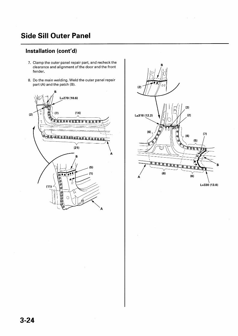
Installation (cont'd)
7. Clamp the outer panel repair part, and recheck theclearance and alignment of the door and the frontfender.
8. Do the main welding. Weld the outer panel repairpart (A) and the patch (B).
(2)
L=330 (13.0)

Center Pillar Outer Panel
Removal
NOTE: This section explains the procedures after removal of all accessories and related parts.For accessories' and related parts' removal procedure, refer to the appropriate Shop Manual.
Mass production body welding position and number [Outer panel , center pillar stiffener andside sill stiffener]
NOTE:• Welding symbols
X: 2-Plate spot welding/®: 3-Plate spot welding/®: 4-Plate spot welding/ 18: MIG plug welding/M: MIG weldingL= Welding length Unit: mm (in.)
• ( ): The number of welds
CENTER PILLAROUTER SEPARATOR
(cont'd)
3-25

Center Pillar Outer Panel
Removal (cont'd)
Construction
• If there is any damage to the center pillar, cut the (A) position and pry off the outer panel, and replace it.
NOTE: Select the cutting positions in consideration of the front side outer panel repair part.
• Check the center pillar stiffener and side sill stiffener position for damage.• When replacing the center pillar stiffener, cut the (B) position at the roof side portion of the outer panel.• When removing the side sill stiffener, and carefully cut the (C) position at the rear wheel arch portion of the outer
panel.• Replace the side sill stiffener and the side sill rear stiffener as an assembly.• Replace the center pillar outer separator and the wheel arch outer separator.
CENTER PILLAR OUTER PANEL
CENTER PILLARSTIFFENER
(B) \,.*, 20 mm (0.8 in.)
STIFFENER
(B)
CENTER INNER PILLAR
OUTER PANEL
CENTER PILLAROUTER SEPARATOR
(C)
OUTER PANELReuse.

Installation
NOTE:• Welding symbols
X: 2-Plate spot welding®: 3-Plate spot welding®: 4-Plate spot welding•: MIG plug weldingM: MIG weldingL= Welding length Unit: mm (in.)
• ( ): The number of welds
1. Clamp the side sill stiffener, and check the bodydimensions.
• Passenger compartment (see page 4-7)• Engine compartment and front floor under view
(see page 1-14)• Front floor and rear floor, under view (see page
4-15)• Repair chart, top view (see page 4-16)• Repair chart, side view (see page 4-18)
2. Tack weld the side sill stiffener (A) and the side sillrear stiffener (B).
[VIEW: ZI
3. Install the new center pillar inner separator (A) onthe side sill stiffener (B).
NOTE: Apply the sealer (C) all the way around theseparator and inside the center pillar stiffener (D)without gaps.
4. Install the new wheel arch outer separator (A) onthe rear inner panel (B).
NOTE: Apply the sealer ('C) all the way around theseparator and inside the outer panel reuse part (D)without gaps.
(cont'd)
3-27

Center Pillar Outer Panel
Installation (cont'd)
5. Weld the patch (A) at the cut section of the bodyside outer panel ( B) and weld the outer panel reusepart (C).
11. Remove the outer panel repair part, and weld thecenter pillar stiffener (A) to the roof side stiffener(B) and the side sill stiffener (C).
B
(4)
6. Rough-cut the front side outer panel repair part,and clamp it to the body.
7. Check the dimensions.
• Front wheelhouse lower member position(see page 4-5)
• Door hinge position (see page 4-6)• Windshield and door opening (see page 4-10)
8. Temporarily install the door, the hood, and thefront fender, then check for differences in level andclearance.Check the external parts fitting position (see page4-12). Make sure the body lines flow smoothly.
9. Trim the cut and joint areas of the outer panelrepair part as needed, and prepare the butt-weldingconnections.
10. From inside the passenger's compartment, weldthe side sill stiffener (A) to the center pillar inner (B)and the inside sill (C).
(9)

12. Weld the patch (A) at the cut section of the bodyside outer panel (B).
[Side sill front section]
40 mm ( 1.6 in.)
(7)
[Center pillar section]
(3)
AIn case of outer panel replacement only
(3)
[Side sill rear section]
13. Install the new center pillar outer separator (A) onthe center pillar stiffener (B).
NOTE: Apply the sealer (C) all the way around theseparator and inside the outer panel repair part (D)without gaps.
(cont'd)
3-29

Center Pillar Outer Panel
Installation (cont'd)
14. Clamp the outer panel repair part, and recheck theclearance and alignment of the door, and the frontfender.
15. Do the main welding. Weld the outer panel repairpart (A) and the patch (B).
(2)
[VIEW: Z]
(5)
(2)
16. Weld the side sill area (see step 8 on page 3-24).
In case of outer panel replacement only

Roof Panel
Removal
NOTE: This section explains the procedures after removal of all accessories and related parts.For accessories' and related parts' removal procedure, refer to the appropriate Shop Manual.
Mass production body welding position and number
NOTE:• Welding symbols
X: 2-Plate spot welding/®: 3-Plate spot welding/®: 4-Plate spot welding /10: MIG plug welding/M: MIG weldingL= Welding length Unit: mm (in.)
• ( ): The number of welds
Without roof panel
(cont'd)
3-31

Roof Panel
Removal (cont'd)
Construction
Remove the rear roof rail mount bolts, drill the welded flange of the front roof rail, and the roof panel.
FRONT INNER UPPEREXTENSION
REAR ROOF RAIL
6x1.Omm \ \18 N•m ( 1.8 kgf • m,13 Ibf•ft) [VIEW: Z]

Installation
NOTE:• Welding symbols
X: 2-Plate spot welding®: 3-Plate spot weldingX: 4-Plate spot welding40: MIG plug weldingW: MIG weldingL= Welding length Unit: mm (in.)
• ( ): The number of welds
1. Clamp the new roof panel.
2. Check the body dimensions.
• Windshield and door opening (see page 4-10)• Tailgate opening (see page 4-11)• Rear pillar gutter position (see page 4-9)• Passenger's compartment (see page 4-7)• Door hinge position (see page 4-6)
3. Tack weld the front and rear corner edge of the roofpanel.
4. Temporarily install the roof molding, thewindshield, the tailgate and the door, then checkfor differences in level and clearance.Check the external parts fitting position (see page4-12). Make sure the body lines flow smoothly.
5. Do the main welding.
• From inside the vehicle, weld the front roof rail(A) and the inner upper extension (B).
• Fix the rear roof rail (C) with the mounting bolts(D).
• Weld the front, rear, and side flange of the roofpanel (E).
• The roof area must be free of burrs and/or sharpedges to prevent damage to the side curtainairbag during deployment.
[VIEW: Z]
(2)
(4)

Rear Side Outer Panel
Removal
NOTE: This section explains the procedures after removal of all accessories and related parts.For accessories' and related parts' removal procedure, refer to the appropriate Shop Manual.
Mass production body welding position and number [Outer panel and rear gutter]
NOTE:• Welding symbols
X: 2-Plate spot welding/®: 3-Plate spot welding/®: 4-Plate spot welding /*: MIG plug welding /M: MIG weldingL= Welding length Unit: mm (in.)
• ( ): The number of welds
(22)
WHEEL ARCH OUTERSEPARATOR
4-plate welding
Rear side outer panelrepair part front edge
(2)
[VIEW: Z] (2)

Construction
• Cut and pry off the rear side outer panel, and replace it.
NOTE: Select the cutting positions in consideration of the rear side outer panel repair part.
• Check the rear pillar gutter position for damage. If necessary, replace the rear pillar gutter lower.• Replace the wheel arch outer separator.
OUTER PANELQUARTER PILLAR STIFFENER
REAR INNER PANEL
OUTER PANEL
REAR PILLARGUTTER MIDDLE
OUTER PANEL
REAR PILLARGUTTER UPPERSTIFFENER

Rear Side Outer Panel
Installation
NOTE:• Welding symbols
X: 2-Plate spot welding®: 3-Plate spot welding®: 4-Plate spot welding•: MIG plug weldingW: MIG weldingL= Welding length Unit: mm (in.)
• ( ): The number of welds
1. Clamp the new rear pillar gutter, rough-cut the rearside outer panel repair part, clamp it to the body.
2. Check the body dimensions.
• Front wheelhouse lower member position(see page 4-5)
• Door hinge position (see page 4-6)• Rear pillar gutter position (see page 4-9)• Windshield and door opening (see page 4-10)• Tailgate opening (see page 4-11)
3. Temporarily install the door, the tailgate, and thequarter glass, then check for differences in leveland clearance.Check the external parts fitting position (see page4-12). Make sure the body lines flow smoothly.
4. Trim the cut and joint areas of the outer panelrepair part as needed, and prepare the butt-weldingconnections. Remove the outer panel repair part.
5. Weld the patch (A) at the cut section of the bodyside outer panel (B).
[Quarter glass section]
40 mm ( 1.6 in.)
6. Install the new wheel arch outer separator (A) onthe rear inner panel (B).
NOTE: Apply the sealer (C) all the way around theseparator and inside the outer panel repair part (D)without gaps.

7. Clamp the outer panel repair part, and recheck theclearance and alignment of the door, the quarterglass, and the tailgate.
8. Do the main welding . Weld the outer panel repairpart (A), and the patch (B).
[Door opening , quarter glass opening and side sill area]
L=330 (13.0)
[Wheel arch portion and rear end]
(8)
(cont'd)
3-37

Rear Side Outer Panel
Installation (cont'd)
9. Weld the rear pillar gutter lower (A), the outer panel I 10. Weld the outer panel (A) and the rear gutter middle(B), and the rear panel (C). (B).

Rear Panel
Removal
NOTE: This section explains the procedures after removal of all accessories and related parts.For accessories' and related parts' removal procedure, refer to the appropriate Shop Manual.
Mass production body welding position and number
NOTE:• Welding symbols
X: 2-Plate spot welding/®: 3-Plate spot welding/®: 4-Plate spot welding/ •: MIG plug welding/M: MIG weldingL= Welding length Unit: mm (in.)
• ( ): The number of welds
REAR PANEL SIDESTIFFENER
(cont'd)
3-39

Rear Panel
Removal (cont'd)
Construction
Cut and pry off the rear panel, and replace it.
REAR PANEL SIDE STIFFENER JACK-UP STIFFENER

Installation
NOTE:• Welding symbols
X: 2-Plate spot welding®: 3-Plate spot welding®: 4-Plate spot welding•: MIG plug weldingW: MIG weldingL= Welding length Unit: mm (in.)
• ( ): The number of welds
1. Clamp the new rear panel.
2. Check the body dimensions.
• Front floor and rear floor, under view (see page4-15)
• Rear panel position (see page 4-8)• Rear pillar gutter position (see page 4-9)• Tailgate opening (see page 4-11)• Repair chart, top view (see page 4-16)• Repair chart, side view (see page 4-18)
3. Tack weld the rear panel into position.
4. Temporarily install the tailgate, then check fordifferences in level and clearance.Check the external parts fitting position (see page4-12). If necessary, check the taillight and the rearbumper positions. Make sure the body lines flowsmoothly.
5. Do the main welding.Weld the rear panel side stiffener (A) to the rearpillar gutter lower (B), and the rear pillar gutterupper stiffener (C).
(2) L=10 (0.4)
(9)
6. Weld the rear panel (A) to the rear pillar gutterlower (B), the rear frame (C), and the rear floor (D).
(15)
3-41

Rear Floor/Rear Frame
Removal
NOTE: This section explains the procedures after removal of all accessories and related parts.For accessories ' and related parts' removal procedure , refer to the appropriate Shop Manual.
Mass production body welding position and number [Rear floor , rear floor side, and rear frameB]
NOTE:• Welding symbols
X: 2-Plate spot welding/®: 3-Plate spot welding/®: 4-Plate spot welding/ *: MIG plug welding/M: MIG weldingL= Welding length Unit: mm (in.)
• ( ): The number of welds
REAR FRAME B
REAR FLOOR SIDE
Outside: (3)Left and right side (8) inside: (2)
REAR FRAME A Rear floor extesion and rear floor Rear frame A and rear frame B

Construction
• Remove the rear floor and the rear floor side, and replace them.• If there is any damage to the rear frame, replace the rear frame B, and repair the rear frame A.
REAR FLOOR
Rear Floor/Rear Frame
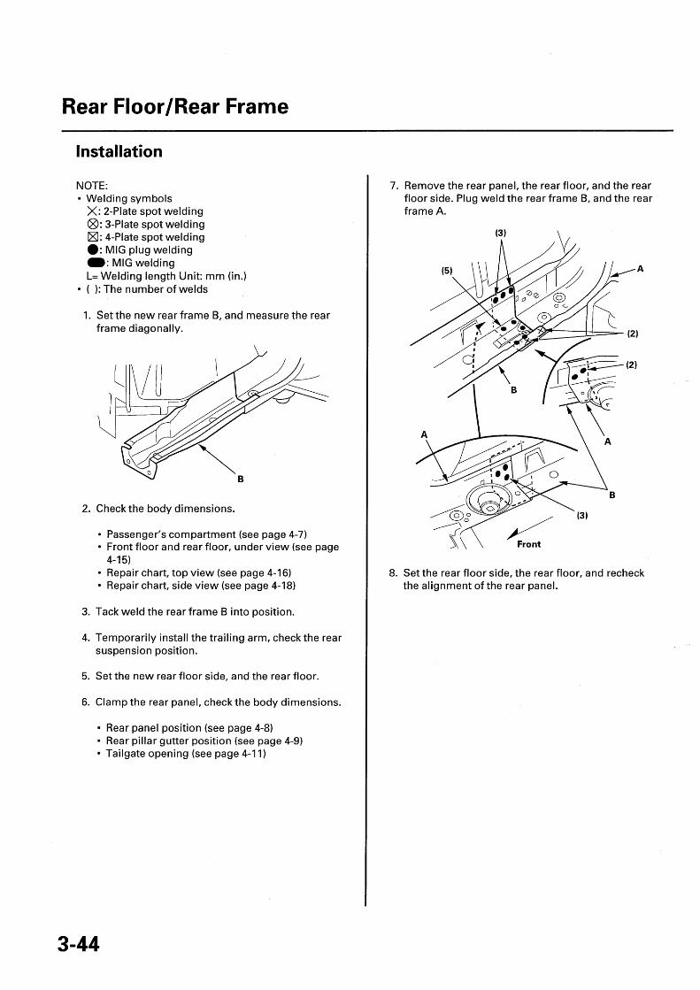
Installation
NOTE:• Welding symbols
X: 2-Plate spot welding®: 3-Plate spot welding®: 4-Plate spot welding10: MIG plug weldingM: MIG weldingL= Welding length Unit: mm (in.)
• ( ): The number of welds
1. Set the new rear frame B, and measure the rearframe diagonally.
2. Check the body dimensions.
• Passenger's compartment (see page 4-7)• Front floor and rear floor, under view (see page
4-15)• Repair chart, top view (see page 4-16)• Repair chart, side view (see page 4-18)
3. Tack weld the rear frame B into position.
4. Temporarily install the trailing arm , check the rearsuspension position.
5. Set the new rear floor side, and the rear floor.
6. Clamp the rear panel , check the body dimensions.
• Rear panel position (see page 4-8)• Rear pillar gutter position (see page 4-9)• Tailgate opening (see page 4-11)
7. Remove the rear panel, the rear floor, and the rearfloor side. Plug weld the rear frame B, and the rearframe A.
8. Set the rear floor side, the rear floor, and recheckthe alignment of the rear panel.

9. Do the main welding. Weld the rear floor side (A)and the floor side extension (B).
10. From the rear wheelhouse side, plug weld the rearframe B, the rear frame A, the rear floor side (C),and the floor side extension (D).
C
(7)
C (4)
(cont'd)
3-45

Rear Floor/Rear Frame
Installation (cont'd)
11. Plug weld the rear floor (A).
Left side: (15)Right side: (15)

Floor Insulators
Insulator Locations
Cut new insulators, and apply as indicated.
NOTE: Before applying, clean and degrease the floor.
®RIGHT DASHBOARD ® FRONT FLOORLOWER INSULATOR FRONT INSULATOR
® LEFT DASHBOARDLOWER INSULATOR
OO RIGHT REAR WHEELHOUSEINSULATOR
[VIEW: X]
® RIGHT FRONT FLOORMIDDLE INSULATOR
®LEFT FRONT FLOORMIDDLE INSULATOR
[VIEW: Y]
® FRONT FLOOR REARCENTER INSULATOR
®REAR FLOORINSULATOR
® LEFT REAR WHEELHOUSSEINSULATOR

Floor Insulators
Insulator Sizes
Unit: mm (in.)o: inner diameter
®RIGHT DASHBOARD LOWER INSULATOR
190 (7.48)136 (5.35)
Co
CoCo
449 63(1.9) (2.5)
54(2.1)
I
I
an
MC)N
CoLn
C)
N
N
oN
Lf
(b LEFT DASHBOARD LOWER INSULATOR
186 (7.32)
90 (3.5)
I
I N.
96(3.8
460.8)
0100-,(3.94)
117 (4 .61) .L87 (3.4)204 (8.04)
®FRONT FLOOR FRONT INSULATOR
IUU 1.46 -14U 15.5"1
09
O
N
NM
330 ( 12.99 )
O
CON
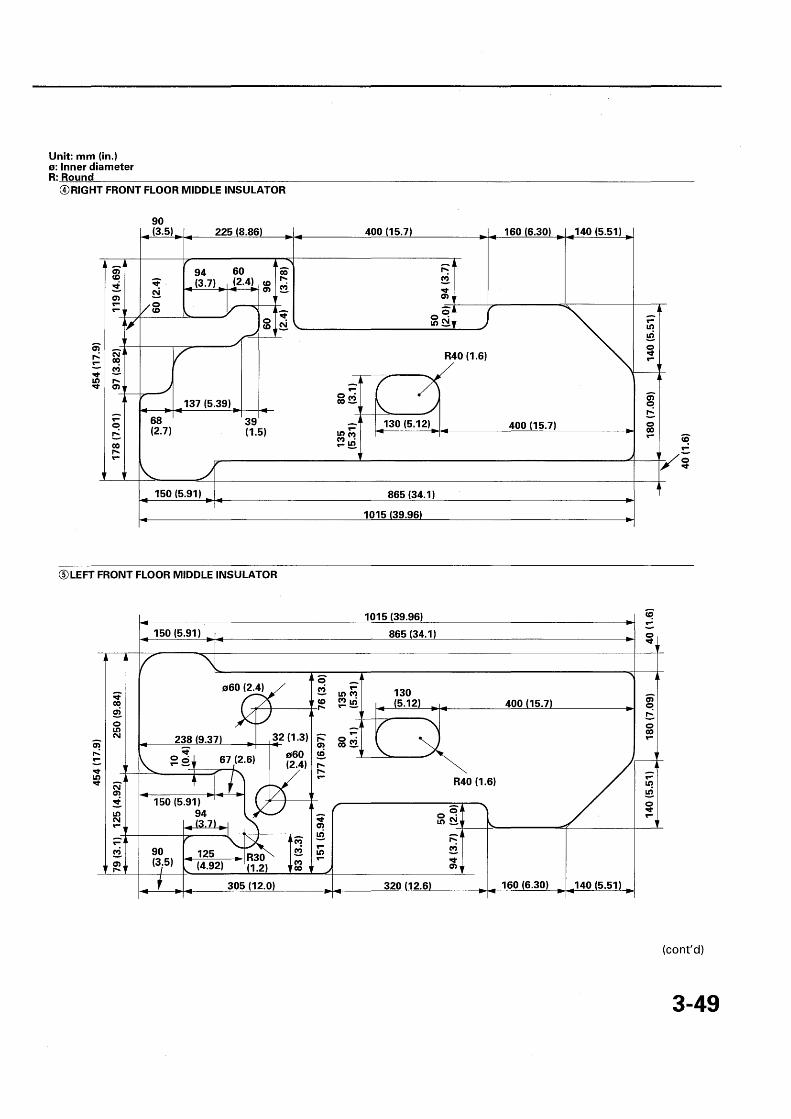
Unit: mm (in.)o: Inner diameterR: Round
®RIGHT FRONT FLOOR MIDDLE INSULATOR
90(3.5)
NCoN
68(2.7)
137 (5.39)
150 (5.91)
225 (8.86)
94 60(3.7) (2.4) CD
OCD
39 r(1.5)
00-
400(15.7)
09
130 (5.12)
865 (34.1)
1015 (39.96)
®LEFT FRONT FLOOR MIDDLE INSULATOR
150 (5.91)
M
J
o60(2.4)
238 (9.37)
f 67(2.6)
150 (5.91)94(3.7)
90(3.5)
32(1.3) R
o60(2.4)
125 R30"(4.92) (1.2)
305 (12.0)
COn
1015 (39.96)
865 (34.1)
R40 (1.6)
O 0Lo
160 (6.30)
400 (15.7)
140 (5.51)
0
320 (12.6 160 (6.30) 140 (5.51)
(cont'd)
3-49

Floor Insulators
Insulator Sizes (cont'd)
Unit: mm (in.)R: Round
(P FRONT FLOOR REAR CENTER INSULATOR
20 20(0.8) (0.8)l
(2A)140 (5.51) 1 90 (3.5)50
00NLLf
M
320 (12.6)
v
LA
M
OO
Co0
®REAR FLOOR INSULATOR
Ln P
Ln
0000
NT-
0
Ln
240 (9.45)
T RIGHT REAR WHEELHOUSE INSULATOR
240 (9.45)
®LEFT REAR WHEELHOUSE INSULATOR
437 (17.2)
192 (7.56)
60(2.4)
128 (5 .04) _, 112 (4.41)
R15 (0 . 6) R15 (0.6)
168 (6.61)
R30 (1.2)
116 (4.57)53 ' -'
(2.1) 350A
315 (12.4)
177 (6.97)
•
L!)N
00O
Co0
r`
MLC
LS)

Body Dimensional Drawings
Upper Body Measuring DimensionsFront Fender Position ................................................... 4-2Engine Compartment ................................................... 4-3Engine/Transmission Mount Position ........................ 4-4Front Wheelhouse Lower Member Position .............. 4-5Door Hinge Position ..................................................... 4-6Passenger's Compartment .......................................... 4-7Rear Panel Position ...................................................... 4-8Rear Pillar Gutter Position ........................................... 4-9Windshield and Door Opening .................................... 4-10Tailgate Opening .......................................................... 4-11External Parts Fitting Position ..................................... 4-12
Under Body Measuring DimensionsFront Subframe Position .............................................. 4-13Engine Compartment and
Front Floor Under View ............................................ 4-14Front Floor and Rear Floor, Under View ..................... 4-15
Frame Repair ChartRepair Chart, Top View ................................................ 4-16Repair Chart, Side View ............................................... 4-18

Upper Body Measuring Dimensions
Front Fender Position
Unit: mm (in.)
A, aBulkhead Upper FrameLocating Hole o15 (0.59)
^y1
rl r- 630(24.8)
B, bFront Fender Mount Bolt (Center of the bolt)
a P O r 1"IA

Engine Compartment
Unit: mm (in.)
B, bBulkhead Upper FrameMount Hole o7 (0.28)
FWindshield LowerLocating Hole 07 (0.28) center

Upper Body Measuring Dimensions
Engine/Transmission Mount Position
Unit: mm (in.)
524(20.6)
972
1221(48.07)
, 1127(44.37)
`1117(43.98)
1167(45.95)
- 1206(47.48)
r1418(16.5)
k^l438(17.2)
(38.3)
1249(49.17)

Front Wheelhouse Lower Member Position
Unit: mm (in.)
JWheelhouse Lower MemberLocating Hole o11 (0.43)
905(35.6)
864(34.0)

Upper Body Measuring Dimensions
Door Hinge Positon
Unit: mm (in.)
MUpper Front Door HingeMount Hole 013 (0 .51) front
0
1095 / \ / //,-P(43.11)
1092(42.99)
1021(40.20)
1134(44.65)
a
0Upper Rear Door HingeMount Hole o13 (0.51) upper
4-6

Passenger 's Compartment
Unit: mm (in.)
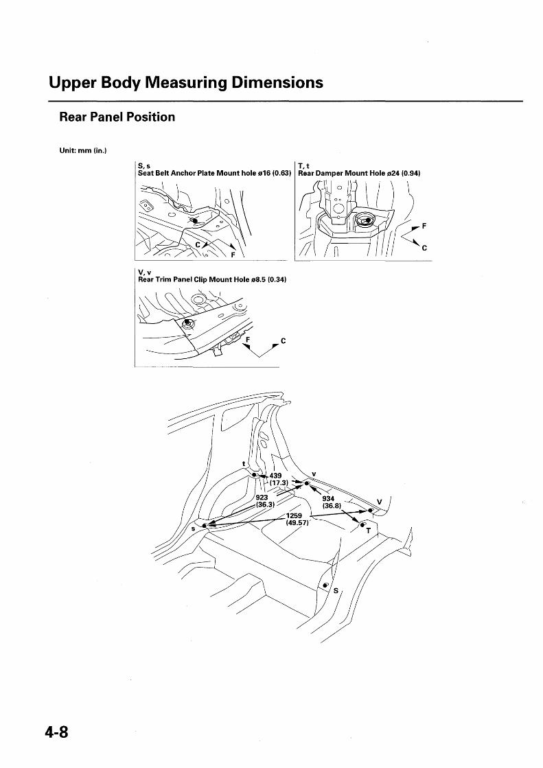
T, tRear Damper Mount Hole o24 (0.94)
1100(43.3l)-
S'sSeat Belt Anchor Plate Mount Hole o16 (0.63)
U, uRear Floor Side Locating Hole o20 (0.79)
1722 ul^(67(67.8 0)
1797(70.75)
1116(43.94)
970(38.2)
1200(47.24) ti
Upper Body Measuring Dimensions
Rear Panel Position
Unit: mm (in.)
S'sSeat Belt Anchor Plate Mount hole o16 (0.63)
V, vRear Trim Panel Clip Mount Hole o8.5 (0.34)
T, tRear Damper Mount Hole 024 (0.94)

Rear Pillar Gutter Position
Unit: mm (in.)
W, wTailgate Support StrutMount Hole 011 (0.43)

Upper Body Measuring Dimensions
Windshield and Door Opening
Unit: mm (in.)AWindshieldLower Locating Holecenter
B, COuter Panel and RoofPanel WindshieldOpening Flange Notch(3 places)
D, E, F, G, H, I, J, KOuter Panel DoorOpening Flange Notch(16 places)
370.5(14.59)

Tailgate Opening
Unit: mm (in.)
LRear Roof RailFlange Notch
NRear Panel UpperStiffener FlangeNotch
MRear Inside UpperExtension Flange End(2 places)

Upper Body Measuring Dimensions
External Parts Fitting Positon
Unit: mm (in.)
Hood Front Fender 2.0
3.0 (0.12 ) (0 08) Rear SideOuter Panel
Rear Door
.om
/ 4.0Front Door (0.16)
Front PillarOuter Panel
Tailgate
Side SillOuter Panel
Roof Panel 7.0
Rear SideOuter Panel
5.0 (0.20)

Under Body Measuring Dimensions
Front Subframe Positon
Unit: mm (in.)
C, cFront Subframe Mount Bolt(Center of the bolt) rear
a
940(37.0)
B, bFront Subframe Mount Bolt(Center of the bolt) front
D, dFront Floor Frame Mount Bolt(Center of the bolt)
500 5(19.7)
905(35.6)
1123(44.21).
1355(53.35)
1647(64.84)
^ (P
.3
jl
97238)
col
A29.7)
341 (63.78)
5; pop
A
627(24.7)
J755 Cj
X1620 /
_1009 ( 52.80 ) 1310 1014-(39.72 ) (51.57 ) (3.92)
D/ /
1357(53.43)

Under Body Measuring Dimensions
Engine Compartment and Front Floor Under View
Unit: mm (in.)
A, aFront Bulkhead Cross -memberLocating Hole o20 (0.79)
B, bFront Side FrameLocating Hole o16 (0.63)
4 792(31.2)n
1163(45.73)
1206 854(47.48) (33.6)
960(37.8)
1029(40.51)
1310 1647(51.57 ) 2(64.84)
887 1620
(34.9) (,( 63.78)
755(29:7)
1341(52.80)
(14.8) 1355(53.35)
1009(39.72)J 7\

Front Floor and Rear Floor, Under View
Unit: mm (in.)
F, fTrailing Arm BracketLocating Hole o20 (0.79)
1094(43.07)
4-15

Frame Repair Chart
Repair Chart Top View
Unit: mm (in.)o: Inner diameteral For engine side mount 015 (0 .59) fronta2 For engine side mount 013 (0 .51) outera3 For engine side mount 015 (0.59) rearb1 For transmission mount 015 (0.59) frontb2 For transmission mount 015 (0.59) wheelhouse sideb3 For transmission mount 015 (0 .59) rearb4 For transmission mount 013 (0.51)
[Manual transmission model]c Front side frame locating hole 016 (0.63)d Front damper center hole 048 (1.89)el For front subframe mount
015 (0 .59) fronte2 For front subframe mount
016 (0 .63) middlee3 R Outrigger locating hole
011 (0.43)e3 L Outrigger locating hole
011 (0 .43) x 15 (0.59) slote4 For front subframe
mount 015 (0.59) rearf Outrigger locating hole
025 (0.98)
b
1.4
2
I^ 231
NNN
Ll>
340 (13.4)
N
76
M
4
N
3U1.30)65 .56)
283 (11.1)
e3 R
e4
e3 L
338 (13.3)409 (16.1)
425(16.7)634 (25.0)
715 (28.2)
f 9 h1 i1\ j1 R
NU,
DF
O
N
b4
(6.10) I
o?0N
N
LC!
CENTER LINE - - -
0Ci
[Manual transmission model]
CENTERLINE }-----I------
OLO 1_155
BASE LINE
00
N
OCDCA
b1
b3
374 (14.7)
359 (14.1)
(2.99)
138(5.43) 1
216 (8.50) r•WI.
V
r^
BASE LINE
g Floor center stiffener locating hole 015 (0.59)h1 Front floor locating hole 050 (1 .97) fronti1 Inside sill locating hole 025 (0 .98) frontj1 R Floor frame locating hole 015 (0 .59) frontj1 L Floor frame locating hole 015 (0 .59) frontj2 R Floor frame locating hole o15 (0 .59) rearj2 L Floor frame locating hole 015 (0 .59) reark Front floor center locating hole 015 (0.59)
1020 (40.16)
805 (31.7900 (35.4)
1291 (50.83)
j1 L
1290 (50.79)1450 (57.09)
1610 (63.39)1700 (66.93)
1925 (75.79)
1935 (76.18)
j2 L
j2 R
j2 R/j2 L1

I
h2
i2
m
n1
n2
01
o2
Front floor cross -member locating hole o25 (0.98)Front floor locating hole o25 (0 .98) rearInside sill locating hole o25 (0 .98) rearTrailing arm gusset locating hole o20 (0.79)Rear seat guide bracket locating hole o9 (0.35) rightRear seat guide bracket locating hole o9 (0.35) left
For trailing arm mount o15 (0 . 59) innerFor trailing arm mount o17 (0.67) outer
i2h2
p Middle floor cross -member locating hole o20 (0.79)q Rear frame A locating hole o15 (0.59)r1 Rear floor locating hole o25 (0 .98) rightr2 Rear floor locating hole o25 (0 .98) left
s For spring base mount hole 15 (0.59 ) x 15 (0 .59) square
t Rear damper center hole o24 (0.94)
u Rear frame B locating hole o20 (0.79)v Rear floor side panel locating hole o20 (0.79)
N
-eF
M
LnCDM
L6
NCO
Co
n M r !U, C^ - Off)
LC)CO
M Co 4e M... d. N to O O
M CD Coa= 0 ; l T
r r ^ rr/
00N
T=FO
MU)
63
A
64
(2.52)
110(4.33)
-234(9.21)
CON
p q
N
NM
COMM
A
373 14.7
h2i2
n1, n
405 (15.9)469 (18.5)
630 (24.8)
m
655 (25.8)862 (33.9)
W1
2000 (78.74)
[Section AA]

Frame Repair Chart
Repair Chart Side View
Unit: mm (in.)0: Inner diameter
al For engine side mount 015 (0 .59) fronta2 For engine side mount 013 (0 .51) outera3 For engine side mount 015 (0 .59) rearb1 For transmission mount 015 (0.59) frontb2 For transmission mount 015 (0.59) wheelhouse sideb3 For transmission mount 015 (0.59) rearb4 For transmission mount o13 (0.51)
[Manual transmission model]c Front side frame locating hole 016 (0.63)d Front damper center hole 048 (1.89)el For front subframe mount 015 (0.59) fronte2 For front subframe mount 016 (0.63) middlee3 R Outrigger locating hole o11 (0.43)e3 L Outrigger locating hole 011 (0 . 43) x 15 (0.59) slote4 For front subframe mount 015 (0.59) rearf Outrigger locating hole 025 (0.98)
CO
MN
MWLn
NJ
MM
BASELINE
N
Ln
LnODM
-T-
NM
1-F
[Manual transmission model]
b4
b2
O
M IODr- 1 Co
BASE LINE
g Floor center stiffener locating hole 015 (0.59)h1 Front floor locating hole 050 (1 .97) fronti1 Inside sill locating hole 025 (0.98) frontj1 R Floor frame locating hole 015 (0 .59) frontj1 L Floor frame locating hole 015 (0.59) frontj2 R Floor frame locating hole 015 (0 .59) rearj2 L Floor frame locating hole 015 (0 .59) reark Front floor center locating hole 015 (0.59)
O, NCO
[Section BB]
MM
O
j2 L

I Front floor cross -member locating hole o25 (0.98)
h2 Front floor locating hole 025 (0 .98) reari2 Inside sill locating hole 825 (0.98) rearm Trailing arm gusset locating hole o20 (0.79)n1 Rear seat guide bracket locating hole o9 (0.35) rightn2 Rear seat guide bracket locating hole o9 (0.35) left
01 For trailing arm mount o15 (0 .59) inner
o2 For trailing arm mount o17 (0.67) outer
n1, n2
p Middle floor cross -member locating hole o20 (0.79)q Rear frame A locating hole o15 (0.59)r1 Rear floor locating hole o25 (0 .98) rightr2 Rear floor locating hole o25 (0.98) lefts For spring base mount hole 15 (0.59 ) x 15 (0.59) square
t Rear damper center hole o24 (0.94)
u Rear frame B locating hole o20 (0.79)v Rear floor side panel locating hole o20 (0.79)

Rust Prevention
Cross Section of Body and SealantsGeneral .......................................................................... 5-2Engine Compartment and Damper Housing ............. 5-3Dashboard Upper and Dashboard Lower .................. 5-4Front Floor ..................................................................... 5-5Rear Floor ...................................................................... 5-6Roof/Rear Pillar Gutter and Rear Panel ...................... 5-7Rear Wheelhouse ......................................................... 5-8
Rust-preventive TreatmentsGeneral .......................................................................... 5-9Undercoating Area ....................................................... 5-10Areas to be Covered by Internal Anti-rust Agents ..... 5-12

Cross Section of Body and Sealants
General
NOTE: Follow the sealer manufacturer 's instructions,and apply the sealer . Note the following items:
• Clean the areas to be sealed with wax and greaseremover.
• Wipe off any excess spot sealer with thinner. Afterthe primer is sprayed, sealer will fill the area wherethe spot sealer was wiped.
• Make sure you can see the sealant when the sealedpart is in its proper location. For the details, refer toengine compartment and damper housing (see page5-3), dashboard upper and dashboard lower(see page 5-4), front floor (see page 5-5), rear floor(see page 5-6), roof panel/rear pillar gutter and rearpanel (see page 5-7), and rear wheelhouse (see page5-8).
• When applying sealant to the engine compartment,the door opening, and the trunk lid gutter, try tomatch the appearance of the factory sealer. Wipe offany excess sealer.
• Apply sealer to any area that a replacement part willcover. Smooth the sealer with a brush if necessary.

Engine Compartment and Damper Housing
INNER UPPER FRONT PILLAR UPPER
OUTER PANELDAMPER HOUSING
DASHBOARD LOWER
STIFFENER
DASHBOARD UPPER DAMPER BASESIDE MEMBER
DASHBOARDDAMPER LOWEREXTENSION
DAMPER BASE
OUTERLOWERPANEL
"--'STIFFENER
INNER LOWER^ I /- ,r-lw^DASHBOARD LOWER
OUTER
STIFFENER
PANELCORNER
INNER LOWER
OUTRIGGER
5-3

Cross Section of Body and Sealants
Dashboard Upper and Dashboard Lower
DASHBOARD UPPER WINDSHIELD LOWER DASHBOARD UPPERSIDE MEMBER \ _. SIDE MEMBER
DASHBOARDUPPER
DASHBOARD UPPER
WINDSHIELDLOWER
DASHBOARD LOWER
INSIDE SILL EXTENSION
DASHBOARD LOWER
INSIDE SILL
INSIDE SILL EXTENSION
SIDE FRAME EXTENSION

Front Floor
SIDE SILL EXTENSION
SIDE SILL EXTENSION
TRAILING ARM BRACKETLOWER GUSSET
MIDDLE FLOORCROSS-MEMBER
TRAILING ARM BRACKETLOWER GUSSET
FRONT FLOOR
FRONT FLOOR
J^jMIDDLE FLOORCROSS -MEMBER
FLOOR FRAMEUPPER STIFFENER

Cross Section of Body and Sealants
Rear Floor
REAR DAMPER REAR FLOOR SIDEEXTENSION REAR WHEELHOUSE EXTENSION
REAR INNER /-- T / I OUTER PANEL
SIDE SILL REAREXTENSION FLOOR SIDE REAR FLOOR SIDE
VREAR FRAME
LOWER GUTTER
REAR FLOOR SIDEREAR PANEL CENTER STIFFENER
REARREAR PANELFLOOR *11 .11
SIDE SILL EXTENSIONMIDDLE FLOOR CROSS-MEMBER STIFFENER
SIDE SILLEXTENSION TRAILING ARM
INNER BRACKET
MIDDLE FLOORCROSS-MEMBER STIFFENER
REAR FLOOR

Roof Panel/Rear Pillar Gutter and Rear Panel
ROOF PANEL OUTER PANEL
LOWER GUTTER
LOWER GUTTEREXTENSION
REAR PANEL\
)I
i
REAR PANEL
► REAR FLOOR1^J
JACK-UPLOWER GUTTER STIFFENER
REAR INNER OUTER PANEL REAR FLOOR SIDEEXTENSION
UPPER GUTTER
5-7

Cross Section of Body and Sealants
Rear Wheelhouse
REAR WHEELHOUSEREAR DAMPER BASE REAR DAMPER BASE
REAR DAMPER- -,- , REAR
REAR DAMPER BASE
DAMPER REAR WHEELHOUSEBASE

Rust-preventive Treatments
General
Undercoat
• Wear goggles or safety glasses to prevent eyeinjury.
• Ventilate when spraying undercoat.
NOTE:• Mask the exhaust system, oxygen sensors, and
suspension mount areas to protect them fromundercoat overspray.
• Follow the undercoating manufacturer's instructions.• Clean the body with wax and grease remover before
the undercoat is sprayed.• Apply the undercoat to the front wheelhouse, rear
wheelhouse, and undersides of the front floor andrear floor, refer to undercoating diagram (see page5-10).
• Coat the bottom of the fuel tank.
Anti-rust Agents
• Anti-rust agents contain substances that areharmful if you breathe or swallow them, or getthem on your skin. Wear coveralls, gloves, eyeprotection, and an approved respirator whileusing such agents.
• Ventilate when spraying an anti-rust agent as itcontains a small amount of organic solvent. Keepsparks, flames and cigarettes away.
NOTE:• Do not spray an anti-rust agent on the brake system
components, exhaust system components andrelated parts, emission control devices in the enginecompartment, ball joint covers, the fuel strainer, orexterior and interior parts.
• Wipe the excess agent with a clean rag dampenedwith light oil.
• Follow the anti-rust agent manufacturer's instructions.• Before applying an anti-rust agent, thoroughly clean
the area to be coated with a steam cleaner, etc., andlet it dry. Waxoyl may be applied to a wet surface.
• Apply the anti-rust agent from the installation holeand the access hole to parts in the outer panel and theframe. Spray the anti-rust agent sufficiently until theexcess amount oozes out when filling the side sill.

Rust-preventive Treatments
Undercoating Area
Apply undercoat to the areas shown.
NOTE:• Coating thickness : 0.4 mm (0.016 in.) MIN.• Front wheelhouse , rear wheelhouse , and dashboard lower coating thickness 0.5 mm (0.02 in.).• Apply the undercoat 10 mm (0.4 in.) from the edge of the welded flanges.
: indicates coating area.
FRONT WHEELHOUSE
FRAME WHEELHOUSE
SIDE SILL OUTER PANEL
INSIDE SILLFLOOR CENTERCROSS-MEMBER
MIDDLE FLOORCROSS-MEMBER
OUTRIGGER \ FRONT FLOOR FRONT FLOOR REAR
[FRONT WHEELHOUSE] [REAR WHEELHOUSE]

[FRONT WHEELHOUSE Section]
[SIDE SILL Section]
DAMPER HOUSING
FRONT SIDE FRAME
OUTER PANEL
REAR FRAME
OUTER PANEL INSIDE SILL EXTENSION
JACK-UP BASE or STIFFENERCoating thickness:more than 0 .5 mm (0.02 in.)
[FRONT FLOOR FRAME Section]FRONT FLOOR
Coating thickness:more than 0.5 mm (0.02 in.)
[MIDDLE FLOOR CROSS-MEMBER Section]
MIDDLE FLOOR CROSS-MEMBERSTIFFENER
/ MIDDLE SEAT CROSS-MEMBER REAR
MIDDLE FLOOR CROSS-MEMBER
FRONT FLOOR
FRONT FLOOR FRAME
[FLOOR CENTER CROSS- MEMBER Section]
DAMPER BASE
FRONT FLOOR
[REAR WHEELHOUSE Section]
CENTER CROSS- MEMBER

Rust-preventive Treatments
Areas to be Covered by Internal Anti-rust Agents
: indicates anti-rust agents.
MIDDLE FLOORCROSS-MEMBER
FLOOR TUNNELCROSS-MEMBER
FLOOR CENTERCROSS-MEMBER
TAILGATE HINGE
TAILGATE
REAR DOOR
REAR DOOR HINGE
HOOD HINGE
FRONT DOOR HINGE
FRONT DOOR
FRONT FENDER

R
HONDAThe Power of Dreams
I © Honda Motor Co .,Ltd. 2008Published by Honda Moto
62TF030Printed
QO HCP A 110.: