fisher fieldvue dlc3010 digital level controller · instruction manual d102748x012 dlc3010 digital...
TRANSCRIPT

www.Fisher.com
Fisher™ FIELDVUE™ DLC3010 Digital LevelController
This manual applies to:
Device Type
Device Revision
Hardware Revision
Firmware Revision
DD Revision
DLC3010
1
1
8
4
ContentsSection 1 Introduction and Specifications 3.Scope of Manual 3. . . . . . . . . . . . . . . . . . . . . . . . . . . . . .Conventions Used in this Manual 3. . . . . . . . . . . . . . . .Description 3. . . . . . . . . . . . . . . . . . . . . . . . . . . . . . . . . .Specifications 4. . . . . . . . . . . . . . . . . . . . . . . . . . . . . . . .Related Documents 5. . . . . . . . . . . . . . . . . . . . . . . . . . .Educational Services 5. . . . . . . . . . . . . . . . . . . . . . . . . . .
Section 2 Installation 15. . . . . . . . . . . . . . . . .Configuration: On the Bench or in the Loop 15. . . . . .Protecting the Coupling and Flexures 15. . . . . . . . . . .Mounting 17. . . . . . . . . . . . . . . . . . . . . . . . . . . . . . . . . . .
Hazardous Area Classifications and Special Instructions for “Safe Use” and Installationsin Hazardous Locations 17. . . . . . . . . . . . . . . . . . . .
Mounting the 249 Sensor 17. . . . . . . . . . . . . . . . . . . .Digital Level Controller Orientation 18. . . . . . . . . . . .Mounting the Digital Level Controller
on a 249 Sensor 20. . . . . . . . . . . . . . . . . . . . . . . . . .Mounting the Digital Level Controller for High
Temperature Applications 20. . . . . . . . . . . . . . . . .Electrical Connections 22. . . . . . . . . . . . . . . . . . . . . . . .
Power Supply 22. . . . . . . . . . . . . . . . . . . . . . . . . . . . . .Field Wiring 23. . . . . . . . . . . . . . . . . . . . . . . . . . . . . . . .Grounding 24. . . . . . . . . . . . . . . . . . . . . . . . . . . . . . . . .
Shielded Wire 24. . . . . . . . . . . . . . . . . . . . . . . . . .Power/Current Loop Connections 25. . . . . . . . . . . . .RTD Connections 25. . . . . . . . . . . . . . . . . . . . . . . . . . .
Two‐Wire RTD Connections 25. . . . . . . . . . . . . . .Three‐Wire RTD Connections 25. . . . . . . . . . . . .
Communication Connections 25. . . . . . . . . . . . . . . . .Test Connections 26. . . . . . . . . . . . . . . . . . . . . . . . . . .Multichannel Installations 26. . . . . . . . . . . . . . . . . . . .
W7977-2
Alarm Jumper 27. . . . . . . . . . . . . . . . . . . . . . . . . . . . . . .Changing Jumper Position 28. . . . . . . . . . . . . . . . . . . .
Loop Test 28. . . . . . . . . . . . . . . . . . . . . . . . . . . . . . . . . . .Installation in Conjunction with a Rosemount�333 HART Tri‐Loop� HART‐to‐AnalogSignal Converter 29. . . . . . . . . . . . . . . . . . . . . . . . . . . . .Multidrop Communication 99. . . . . . . . . . . . . . . . . . . .
Section 3 Overview 31. . . . . . . . . . . . . . . . . . .Section 4 Setup and Calibration 35. . . . . . . .Initial Setup 35. . . . . . . . . . . . . . . . . . . . . . . . . . . . . . . . .Configuration Advice 36. . . . . . . . . . . . . . . . . . . . . . . . .Preliminary Considerations 36. . . . . . . . . . . . . . . . . . . .
Write Protect 36. . . . . . . . . . . . . . . . . . . . . . . . . . . . . .Guided Setup 36. . . . . . . . . . . . . . . . . . . . . . . . . . . . . . .
Coupling 39. . . . . . . . . . . . . . . . . . . . . . . . . . . . . . . . . .Manual Setup 40. . . . . . . . . . . . . . . . . . . . . . . . . . . . . . .
Sensor 40. . . . . . . . . . . . . . . . . . . . . . . . . . . . . . . . . . . .Variables 42. . . . . . . . . . . . . . . . . . . . . . . . . . . . . . . . . .Ranging 43. . . . . . . . . . . . . . . . . . . . . . . . . . . . . . . . . . .Process Conditions 44. . . . . . . . . . . . . . . . . . . . . . . . . .Device Identification 48. . . . . . . . . . . . . . . . . . . . . . . .
Instruction ManualD102748X012
DLC3010 Digital Level ControllerJuly 2019
Instruction ManualD102748X012
DLC3010 Digital Level ControllerJuly 2019
2
Communications 48. . . . . . . . . . . . . . . . . . . . . . . . . . .Polling Address 48. . . . . . . . . . . . . . . . . . . . . . . . .Burst Mode 48. . . . . . . . . . . . . . . . . . . . . . . . . . . .Burst Option 49. . . . . . . . . . . . . . . . . . . . . . . . . . .
Instrument Display 49. . . . . . . . . . . . . . . . . . . . . . . . . .Alert Setup 51. . . . . . . . . . . . . . . . . . . . . . . . . . . . . . . . .
Primary Variable 51. . . . . . . . . . . . . . . . . . . . . . . . . . . .Temperature 56. . . . . . . . . . . . . . . . . . . . . . . . . . . . . . .
Calibration 58. . . . . . . . . . . . . . . . . . . . . . . . . . . . . . . . . .Primary 58. . . . . . . . . . . . . . . . . . . . . . . . . . . . . . . . . . .
Guided Calibration 58. . . . . . . . . . . . . . . . . . . . . .Full Calibration 59. . . . . . . . . . . . . . . . . . . . . . . . .�Min/Max Calibration 59. . . . . . . . . . . . . . . . . . .�Two Point Calibration 59. . . . . . . . . . . . . . . . . .�Weight Calibration 59. . . . . . . . . . . . . . . . . . . .Theoretical Calibration 60. . . . . . . . . . . . . . . . . . .Partial Calibration 61. . . . . . . . . . . . . . . . . . . . . . .�Capture Zero 61. . . . . . . . . . . . . . . . . . . . . . . . .�Trim Gain 61. . . . . . . . . . . . . . . . . . . . . . . . . . . .�Trim Zero 61. . . . . . . . . . . . . . . . . . . . . . . . . . . .
Secondary 62. . . . . . . . . . . . . . . . . . . . . . . . . . . . . . . . .Temperature Calibration 62. . . . . . . . . . . . . . . . .�Trim Instrument Temperature 62. . . . . . . . . .�Trim Process Temperature 62. . . . . . . . . . . . . .Analog Output CalibratIon 63. . . . . . . . . . . . . . . .�Scaled D/A Trim 63. . . . . . . . . . . . . . . . . . . . . .
Calibration Examples 63. . . . . . . . . . . . . . . . . . . . . . . .Calibration with Standard displacer and
Torque Tube 63. . . . . . . . . . . . . . . . . . . . . . . . .Calibration with Overweight Displacer 65. . . . . .Density Applications - with Standard Displacer
and Torque Tube 66. . . . . . . . . . . . . . . . . . . . .Calibration at Process Conditions (Hot Cut‐Over)
when input cannot be varied 67. . . . . . . . . . .Entering Theoretical Torque Tube Rates 68. . . .Excessive Mechanical Gain 68. . . . . . . . . . . . . . . .Determining the SG of an Unknown Fluid 69. . .
Accuracy Considerations 69. . . . . . . . . . . . . . . . . . . . .Effect of Proportional Band 69. . . . . . . . . . . . . . .Density Variations in Interface Applications 69. .Extreme Temperatures 70. . . . . . . . . . . . . . . . . . .Temperature Compensation 70. . . . . . . . . . . . . .
Section 5 Service Tools 71. . . . . . . . . . . . . . .Active Alerts 71. . . . . . . . . . . . . . . . . . . . . . . . . . . . . . . .Variables 73. . . . . . . . . . . . . . . . . . . . . . . . . . . . . . . . . . .Maintenance 77. . . . . . . . . . . . . . . . . . . . . . . . . . . . . . . .
Section 6 Maintenance and Troubleshooting 79. . . . . . . . . . . . . . . . . . . .Diagnostic Messages 79. . . . . . . . . . . . . . . . . . . . . . . . .Hardware Diagnostics 80. . . . . . . . . . . . . . . . . . . . . . . .Test Terminals 82. . . . . . . . . . . . . . . . . . . . . . . . . . . . . .Removing the Digital LevelController from the Sensor 82. . . . . . . . . . . . . . . . . . . .
Removing the DLC3010 Digital Level Controllerfrom a 249 Sensor 83. . . . . . . . . . . . . . . . . . . . . . . .
Standard Temperature Applications 83. . . . . . . .High Temperature Applications 84. . . . . . . . . . .
LCD Meter Assembly 84. . . . . . . . . . . . . . . . . . . . . . . . .Removing the LCD Meter Assembly 85. . . . . . . . . . . .Replacing the LCD Meter Assembly 85. . . . . . . . . . . .
Electronics Module 86. . . . . . . . . . . . . . . . . . . . . . . . . . .Removing the Electronics Module 86. . . . . . . . . . . . .Replacing the Electronics Module 86. . . . . . . . . . . . .
Terminal Box 87. . . . . . . . . . . . . . . . . . . . . . . . . . . . . . . .Removing the Terminal Box 87. . . . . . . . . . . . . . . . . .Replacing the Terminal Box 87. . . . . . . . . . . . . . . . . . .
Removing and Replacing the Inner Guideand Access Handle Assembly 88. . . . . . . . . . . . . . . . . .Lever Assembly 89. . . . . . . . . . . . . . . . . . . . . . . . . . . . . .
Removing the Lever Assembly 89. . . . . . . . . . . . . . . .Replacing the Lever Assembly 90. . . . . . . . . . . . . . . .
Packing for Shipment 90. . . . . . . . . . . . . . . . . . . . . . . . .Section 7 Parts 91. . . . . . . . . . . . . . . . . . . . . .Parts Ordering 91. . . . . . . . . . . . . . . . . . . . . . . . . . . . . . .Mounting Kits 91. . . . . . . . . . . . . . . . . . . . . . . . . . . . . . .Repair Kits 91. . . . . . . . . . . . . . . . . . . . . . . . . . . . . . . . . .Parts List 92. . . . . . . . . . . . . . . . . . . . . . . . . . . . . . . . . . .
DLC3010 Digital Level Controllers 92. . . . . . . . . . . . .Transducer Assembly 93. . . . . . . . . . . . . . . . . . . . . . . .Terminal Box Assembly 94. . . . . . . . . . . . . . . . . . . . . .Terminal Box Cover Assembly 94. . . . . . . . . . . . . . . . .Mounting Parts 95. . . . . . . . . . . . . . . . . . . . . . . . . . . . .
249 Sensors with Heat Insulator 95. . . . . . . . . . .
Appendix A Principle of Operation 99. . . . . .HART Communication 99. . . . . . . . . . . . . . . . . . . . . . . .Digital Level Controller Operation 100. . . . . . . . . . . . .
Appendix B Field Communicator �Menu Tree 105. . . . . . . . . . . . . . . . . . . . . . .Glossary 112. . . . . . . . . . . . . . . . . . . . . . . . . . .

Instruction ManualD102748X012
DLC3010 Digital Level ControllerIntroduction and Specifications
July 2019
3
Section 1 Introduction and Specifications
Scope of Manual1‐1‐
This instruction manual includes specifications, installation, operating, and maintenance information for FIELDVUEDLC3010 digital level controllers.
This instruction manual supports the 475 Field Communicator or the AMS Trex™ Device Communicator with devicedescription revision 4, used with DLC3010 instruments with firmware revision 8. You can obtain information about theprocess, instrument, or sensor using the Field Communicator. Contact your Emerson sales office to obtain theappropriate software.
Note
AMS Suite: Intelligent Device Manager can also be used to calibrate and configure the DLC3010, and to obtain information aboutthe process, instrument, or sensor.
Do not install, operate, or maintain a DLC3010 digital level controller without being fully trained and qualified ininstrument, valve, actuator, and accessory installation, operation, and maintenance. To avoid personal injury orproperty damage, it is important to carefully read, understand, and follow all of the contents of this manual, includingall safety cautions and warnings. If you have any questions about these instructions, contact your Emerson sales office.
Conventions Used in this ManualThis manual describes using the Field Communicator to calibrate and configure the digital level controller.
Procedures that require the use of the Field Communicator have the text path and the sequence of numeric keysrequired to display the desired Field Communicator menu.
For example, to access the Full Calibration menu:
Field Communicator Configure > Calibration > Primary > Full Calibration (2-4-1-2)
Menu selections are shown in italics, e.g., Calibrate. An overview of the Field Communicator menu structure is shownin Appendix B.
Description
DLC3010 Digital Level ControllersDLC3010 digital level controllers (figure 1‐1) are used with level sensors to measure liquid level, the level of interfacebetween two liquids, or liquid specific gravity (density). Changes in level or specific gravity exert a buoyant force on a

Instruction ManualD102748X012
DLC3010 Digital Level ControllerIntroduction and SpecificationsJuly 2019
4
displacer, which rotates the torque tube shaft. This rotary motion is applied to the digital level controller, transformedto an electrical signal and digitized. The digital signal is compensated and processed per user configurationrequirements, and converted back to a 4‐20 mA analog electrical signal. The resulting current output signal is sent toan indicating or final control element.
Figure 1‐1. FIELDVUE DLC3010 Digital Level Controller
W7977-2
DLC3010 digital level controllers are communicating, microprocessor‐based level, interface, or density sensinginstruments. In addition to the normal function of providing a 4‐20 milliampere current signal, DLC3010 digital levelcontrollers, using the HART� communications protocol, give easy access to information critical to process operation.You can gain information from the process, the instrument, or the sensor using a Field Communicator with devicedescriptions (DDs) compatible with DLC3010 digital level controllers. The Field Communicator may be connected atthe digital level controller or at a field junction box.
Using the Field Communicator, you can perform several operations with the DLC3010 digital level controller. You caninterrogate, configure, calibrate, or test the digital level controller. Using the HART protocol, information from thefield can be integrated into control systems or be received on a single loop basis.
DLC3010 digital level controllers are designed to directly replace standard pneumatic and electro‐pneumatic leveltransmitters. DLC3010 digital level controllers mount on a wide variety of caged and cageless 249 level sensors. Theymount on other manufacturers' displacer type level sensors through the use of mounting adaptors.
249 Caged Sensors (see table 1‐6)� 249, 249B, 249BF, 249C, 249K, and 249L sensors side‐mount on the vessel with the displacer mounted inside a cage
outside the vessel. (The 249BF caged sensor is available only in Europe, Middle East, and Africa.)
249 Cageless Sensors (see table 1‐7)� 249BP, 249CP, and 249P sensors top‐mount on the vessel with the displacer hanging down into the vessel.
� 249VS sensor side‐mounts on the vessel with the displacer hanging out into the vessel.
� 249W wafer‐style sensor mounts on top of a vessel or on a customer‐supplied cage.
SpecificationsSpecifications for the DLC3010 digital level controller are shown in table 1‐1. Specifications for the 249 sensor areshown in table 1‐3. Specifications for the Field Communicator can be found in the product manual for the FieldCommunicator.
Instruction ManualD102748X012
DLC3010 Digital Level ControllerIntroduction and Specifications
July 2019
5
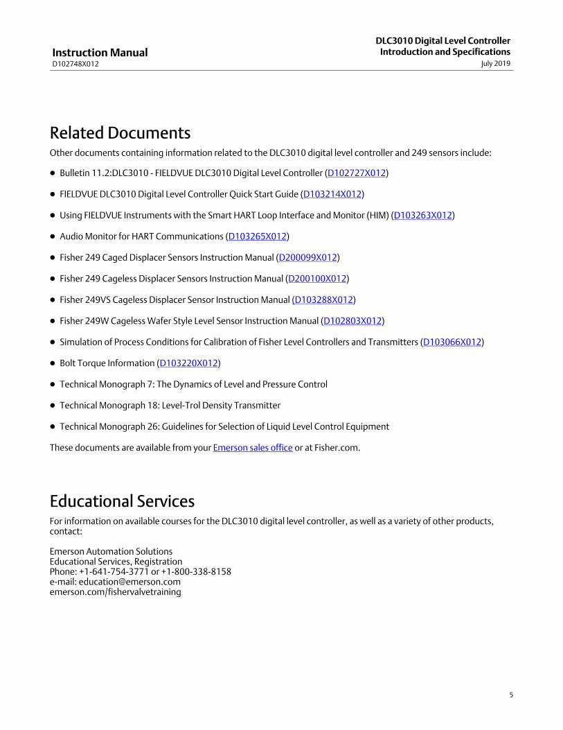
Related Documents Other documents containing information related to the DLC3010 digital level controller and 249 sensors include:
� Bulletin 11.2:DLC3010 - FIELDVUE DLC3010 Digital Level Controller (D102727X012)
� FIELDVUE DLC3010 Digital Level Controller Quick Start Guide (D103214X012)
� Using FIELDVUE Instruments with the Smart HART Loop Interface and Monitor (HIM) (D103263X012)
� Audio Monitor for HART Communications (D103265X012)
� Fisher 249 Caged Displacer Sensors Instruction Manual (D200099X012)
� Fisher 249 Cageless Displacer Sensors Instruction Manual (D200100X012)
� Fisher 249VS Cageless Displacer Sensor Instruction Manual (D103288X012)
� Fisher 249W Cageless Wafer Style Level Sensor Instruction Manual (D102803X012)
� Simulation of Process Conditions for Calibration of Fisher Level Controllers and Transmitters (D103066X012)
� Bolt Torque Information (D103220X012)
� Technical Monograph 7: The Dynamics of Level and Pressure Control
� Technical Monograph 18: Level‐Trol Density Transmitter
� Technical Monograph 26: Guidelines for Selection of Liquid Level Control Equipment
These documents are available from your Emerson sales office or at Fisher.com.
Educational Services For information on available courses for the DLC3010 digital level controller, as well as a variety of other products,contact:
Emerson Automation SolutionsEducational Services, RegistrationPhone: +1-641-754-3771 or +1-800-338-8158e‐mail: [email protected]/fishervalvetraining

Instruction ManualD102748X012
DLC3010 Digital Level ControllerIntroduction and SpecificationsJuly 2019
6
Table 1‐1. DLC3010 Digital Level Controller Specifications
Available Configurations
DLC3010 Digital Level Controller:Mounts on caged and cageless 249 sensors. Seetables 1‐6 and 1‐7 and sensor description.
Function: Transmitter
Communications Protocol: HART
Input Signal
Level, Interface, or Density: Rotary motion of torquetube shaft proportional to changes in liquid level,interface level, or density that change the buoyancyof a displacer.
Process Temperature: Interface for 2‐ or 3‐wire 100ohm platinum RTD for sensing process temperature,or optional user‐entered target temperature topermit compensating for changes in specific gravity
Output Signal
Analog: 4‐20 milliamperes DC (��directaction—increasing level, interface, or densityincreases output; or ��reverse action—increasinglevel, interface, or density decreases output)
High saturation: 20.5 mALow saturation: 3.8 mAHigh alarm: 22.5 mALow Alarm: 3.7 mA
Only one of the above high/low alarm definitions isavailable in a given configuration. NAMUR NE 43compliant when high alarm level is selected.
Digital: HART 1200 Baud FSK (frequency shift keyed)
HART impedance requirements must be met toenable communication. Total shunt impedanceacross the master device connections (excluding themaster and transmitter impedance) must be between230 and 600 ohms. The transmitter HART receiveimpedance is defined as:Rx: 42K ohms and Cx: 14 nF
Note that in point‐to‐point configuration, analog anddigital signalling are available. The instrument may bequeried digitally for information, or placed in Burstmode to regularly transmit unsolicited processinformation digitally. In multi‐drop mode, the outputcurrent is fixed at 4 mA, and only digitalcommunication is available.
Performance
PerformanceCriteria
DLC3010Digital LevelController(1)
w/ NPS 3249W, Using
a 14‐inchDisplacer
w/ All Other249 Sensors
IndependentLinearity
�0.25% ofoutput span
�0.8% ofoutput span
�0.5% ofoutput span
Hysteresis<0.2% of
output span- - - - - -
Repeatability�0.1% of fullscale output
�0.5% ofoutput span
�0.3% ofoutput span
Dead Band<0.05% ofinput span
- - - - - -
Hysteresis plusDeadband
- - -<1.0% of
output span<1.0% of
output span
NOTE: At full design span, reference conditions.1. To lever assembly rotation inputs.
At effective proportional band (PB)<100%, linearity,dead band, and repeatability are derated by the factor(100%/PB)
Operating Influences
Power Supply Effect: Output changes <±0.2% of fullscale when supply varies between min. and maxvoltage specifications.
Transient Voltage Protection: The loop terminals areprotected by a transient voltage suppressor. Thespecifications are as follows:
Pulse Waveform Max VCL(Clamping
Voltage) (V)
Max IPP(Pulse Peak
@ Current) (A)Rise Time
��s)
Decay to
50% ��s)
10 1000 93.6 16
8 20 121 83
Note: μs = microsecond
Ambient Temperature: The combined temperatureeffect on zero and span without the 249 sensor is lessthan 0.03% of full scale per degree Kelvin over theoperating range -40 to 80�C (-40 to 176�F)
Process Temperature: The torque rate is affected bythe process temperature (see figure 1‐2 and 1‐3). Theprocess density may also be affected by the processtemperature.
Process Density: The sensitivity to error in knowledgeof process density is proportional to the differentialdensity of the calibration. If the differential specificgravity is 0.2, an error of 0.02 specific gravity units inknowledge of a process fluid density represents 10%of span.
-continued-

Instruction ManualD102748X012
DLC3010 Digital Level ControllerIntroduction and Specifications
July 2019
7
Table 1‐1. DLC3010 Digital Level Controller Specifications (continued)
Electromagnetic Compatibility
Meets EN 61326‐1:2013 and EN 61326‐2‐3:2006�Immunity—Industrial locations per Table 2 of��EN 61326‐1 and Table AA.2 of EN 61326‐2‐3.��Performance is shown in table 1‐2 below.�Emissions—Class A��ISM equipment rating: Group 1, Class A
Supply Requirements (See figure 2‐10)
12 to 30 volts DC���; 22.5 mAInstrument has reverse polarity protection.
A minimum compliance voltage of 17.75 is requiredto guarantee HART communication.
Compensation
Transducer compensation: for ambient temperature.Density parameter compensation: for processtemperature (requires user‐supplied tables).Manual compensation: for torque tube rate at targetprocess temperature is possible.
Digital Monitors
Linked to jumper‐selected Hi (factory default) or Loanalog alarm signal:Torque tube position transducer: Drive monitor andsignal reasonableness monitorUser‐configurable alarms: Hi‐Hi and Lo‐Lo Limitprocess alarms
HART‐readable only:RTD signal reasonableness monitor: When RTDinstalledProcessor free‐time monitor.Writes‐remaining in Non Volatile Memory monitor.User‐configurable alarms: Hi and Lo limit processalarms, Hi and Lo limit process temperature alarms,and Hi and Lo limit electronics temperature alarms
Diagnostics
Output loop current diagnostic.LCD meter diagnostic.Spot specific gravity measurement in level mode: usedto update specific gravity parameter to improveprocess measurementDigital signal‐tracing capability: by review of“troubleshooting variables”, andBasic trending capability for PV, TV and SV.
LCD Meter Indications
LCD meter indicates analog output on a percent scalebar graph. The meter also can be configured todisplay:
Process variable in engineering units only.Percent range only.Percent range alternating with process variable orProcess variable, alternating with process temperature(and degrees of pilot shaft rotation).
Electrical Classification
Pollution Degree IV, Overvoltage Category II per IEC61010 clause 5.4.2 d
Hazardous Area:
CSA— Intrinsically Safe, Explosion‐proof, Division 2,Dust Ignition‐proof
FM— Intrinsically Safe, Explosion‐proof,Non‐incendive, Dust Ignition‐proof
ATEX— Intrinsically Safe, Type n, Flameproof
IECEx— Intrinsically Safe, Type n, Flameproof
Electrical Housing:
CSA— Type 4X ATEX— IP66
FM— NEMA 4X IECEx— IP66
Other Classifications/CertificationsCUTR— Customs Union Technical Regulations (Russia,Kazakhstan, Belarus, and Armenia)INMETRO— National Institute of Metrology,Standardization, and Industrial Quality (Brazil)KGS— Korea Gas Safety Corporation (South Korea)NEPSI— National Supervision and Inspection Centrefor Explosion Protection and Safety ofInstrumentation (China)PESO CCOE— Petroleum and Explosives SafetyOrganisation - Chief Controller of Explosives (India)TIIS— Technology Institution of Industrial Safety(Japan)Contact your Emerson sales office forclassification/certification specific information
Minimum Differential Specific Gravity
With a nominal 4.4 degrees torque tube shaftrotation for a 0 to 100 percent change in liquid level(specific gravity=1), the digital level controller can beadjusted to provide full output for an input range of5% of nominal input span. This equates to a minimumdifferential specific gravity of 0.05 with standardvolume displacers.
-continued-
Instruction ManualD102748X012
DLC3010 Digital Level ControllerIntroduction and SpecificationsJuly 2019
8
Table 1‐1. DLC3010 Digital Level Controller Specifications (continued)
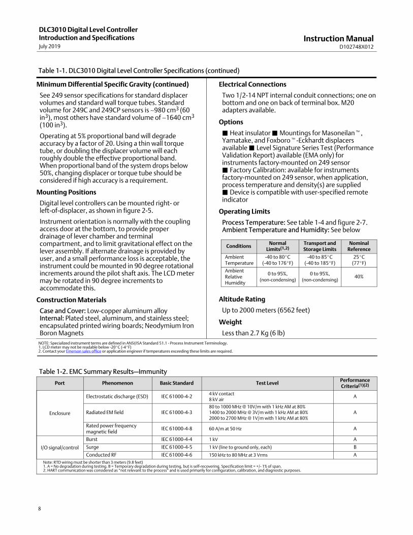
Minimum Differential Specific Gravity (continued)
See 249 sensor specifications for standard displacervolumes and standard wall torque tubes. Standardvolume for 249C and 249CP sensors is ∼980 cm3 (60in3), most others have standard volume of ∼1640 cm3
(100 in3).
Operating at 5% proportional band will degradeaccuracy by a factor of 20. Using a thin wall torquetube, or doubling the displacer volume will eachroughly double the effective proportional band.When proportional band of the system drops below50%, changing displacer or torque tube should beconsidered if high accuracy is a requirement.
Mounting Positions
Digital level controllers can be mounted right‐ orleft‐of‐displacer, as shown in figure 2‐5.
Instrument orientation is normally with the couplingaccess door at the bottom, to provide properdrainage of lever chamber and terminalcompartment, and to limit gravitational effect on thelever assembly. If alternate drainage is provided byuser, and a small performance loss is acceptable, theinstrument could be mounted in 90 degree rotationalincrements around the pilot shaft axis. The LCD metermay be rotated in 90 degree increments toaccommodate this.
Construction Materials
Case and Cover: Low‐copper aluminum alloyInternal: Plated steel, aluminum, and stainless steel;encapsulated printed wiring boards; Neodymium IronBoron Magnets
Electrical Connections
Two 1/2‐14 NPT internal conduit connections; one onbottom and one on back of terminal box. M20adapters available.
Options
� Heat insulator � Mountings for Masoneilan�,Yamatake, and Foxboro�‐Eckhardt displacersavailable � Level Signature Series Test (PerformanceValidation Report) available (EMA only) forinstruments factory‐mounted on 249 sensor� Factory Calibration: available for instrumentsfactory‐mounted on 249 sensor, when application,process temperature and density(s) are supplied� Device is compatible with user‐specified remoteindicator
Operating Limits
Process Temperature: See table 1‐4 and figure 2‐7.Ambient Temperature and Humidity: See below
ConditionsNormal
Limits(1,2)Transport andStorage Limits
NominalReference
AmbientTemperature
-40 to 80�C(-40 to 176�F)
-40 to 85�C(-40 to 185�F)
25�C(77�F)
AmbientRelativeHumidity
0 to 95%,(non‐condensing)
0 to 95%,(non‐condensing)
40%
Altitude Rating
Up to 2000 meters (6562 feet)
Weight
Less than 2.7 Kg (6 lb)
NOTE: Specialized instrument terms are defined in ANSI/ISA Standard 51.1 - Process Instrument Terminology.1. LCD meter may not be readable below -20�C (-4�F)2. Contact your Emerson sales office or application engineer if temperatures exceeding these limits are required.
Table 1‐2. EMC Summary Results—Immunity
Port Phenomenon Basic Standard Test LevelPerformanceCriteria(1)(2)
Enclosure
Electrostatic discharge (ESD) IEC 61000‐4‐24 kV contact8 kV air
A
Radiated EM field IEC 61000‐4‐380 to 1000 MHz @ 10V/m with 1 kHz AM at 80%1400 to 2000 MHz @ 3V/m with 1 kHz AM at 80%2000 to 2700 MHz @ 1V/m with 1 kHz AM at 80%
A
Rated power frequencymagnetic field
IEC 61000‐4‐8 60 A/m at 50 Hz A
I/O signal/control
Burst IEC 61000‐4‐4 1 kV A
Surge IEC 61000‐4‐5 1 kV (line to ground only, each) B
Conducted RF IEC 61000‐4‐6 150 kHz to 80 MHz at 3 Vrms A
Note: RTD wiring must be shorter than 3 meters (9.8 feet)1. A = No degradation during testing. B = Temporary degradation during testing, but is self‐recovering. Specification limit = +/- 1% of span.2. HART communication was considered as “not relevant to the process” and is used primarily for configuration, calibration, and diagnostic purposes.

Instruction ManualD102748X012
DLC3010 Digital Level ControllerIntroduction and Specifications
July 2019
9
Figure 1‐2. Theoretical Reversible Temperature Effect on Common Torque Tube Materials, Degrees Celsius
TORQUE RATE REDUCTION(NORMALIZED MODULUS OF RIGIDITY)
Gn
orm
TEMPERATURE (�C)
N05500
N06600
N10276
S3160020 40 60 80 100 120 140 160 180 200 220 240 260 280 300 320 340 360 380 400 420
1.00
0.96
0.92
0.88
0.84
0.82
0.80
0.90
0.86
0.98
0.94
NOTES: 1� DUE TO THE PERMANENT DRIFT THAT OCCURS NEAR AND ABOVE 260�C, N05500 IS NOT RECOMMENDED FOR TEMPERATURES ABOVE 232�C. 2 �FOR PROCESS TEMPERATURES BELOW -29�C AND ABOVE 204�C SENSOR MATERIALS MUST BE APPROPRIATE FOR THE PROCESS; SEE TABLE 1‐4.
1
Gn
orm
TEMPERATURE (�C)
1.10
1.08
1.06
1.04
1.02
1.01
1.00
1.05
1.03
1.09
1.07
TORQUE RATE AMPLIFICATION(NORMALIZED MODULUS OF RIGIDITY)
CRYOGENIC
N05500
S31600
-200 -180 -160 -140 -120 -100 -80 -60 -40 -20 0 20 40
Instruction ManualD102748X012
DLC3010 Digital Level ControllerIntroduction and SpecificationsJuly 2019
10
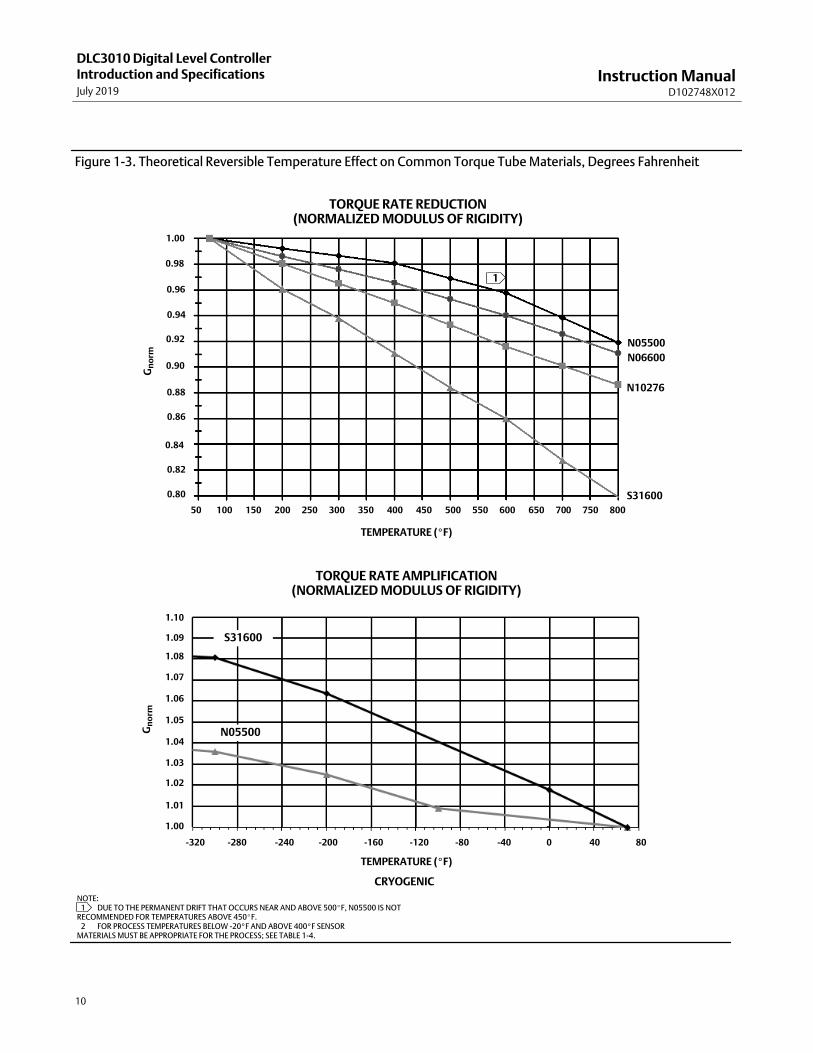
Figure 1‐3. Theoretical Reversible Temperature Effect on Common Torque Tube Materials, Degrees Fahrenheit
TORQUE RATE AMPLIFICATION(NORMALIZED MODULUS OF RIGIDITY)
TEMPERATURE (�F)
Gn
orm
1.10
1.08
1.06
1.04
1.02
1.01
1.00
1.05
1.03
1.09
1.07
-320 -280 -240 -200 -160 -120 -80 -40 0 40 80
TORQUE RATE REDUCTION(NORMALIZED MODULUS OF RIGIDITY)
TEMPERATURE (�F)
N05500
N06600
N10276
S31600
50 100 150 200 250 300 350 400 450 500 550 600 650 700 750 800
1.00
0.96
0.92
0.88
0.84
0.82
0.80
0.90
0.86
0.98
0.94
Gn
orm
1
NOTE: 1� DUE TO THE PERMANENT DRIFT THAT OCCURS NEAR AND ABOVE 500�F, N05500 IS NOT RECOMMENDED FOR TEMPERATURES ABOVE 450�F. 2 �FOR PROCESS TEMPERATURES BELOW -20�F AND ABOVE 400�F SENSORMATERIALS MUST BE APPROPRIATE FOR THE PROCESS; SEE TABLE 1‐4.
CRYOGENIC
N05500
S31600

Instruction ManualD102748X012
DLC3010 Digital Level ControllerIntroduction and Specifications
July 2019
11
Table 1‐3. 249 Sensor Specifications
Input Signal
Liquid Level or Liquid‐to‐Liquid Interface Level:From 0 to 100 percent of displacer lengthLiquid Density: From 0 to 100 percent ofdisplacement force change obtained with givendisplacer volume—standard volumes are ��980 cm3
(60 inches3) for 249C and 249CP sensors or ��1640cm3 (100 inches3) for most other sensors; othervolumes available depending upon sensorconstruction
Sensor Displacer Lengths
See tables 1‐6 and 1‐7 footnotes
Sensor Working Pressures
Consistent with applicable ANSIpressure/temperature ratings for the specific sensorconstructions shown in tables 1‐6 and 1‐7
Caged Sensor Connection Styles
Cages can be furnished in a variety of end connectionstyles to facilitate mounting on vessels; the
equalizing connection styles are numbered and areshown in figure 1‐4.
Mounting Positions
Most level sensors with cage displacers have arotatable head. The head may be rotated through360 degrees to any of eight different positions, asshown in figure 2‐5.
Construction Materials
See tables 1‐5, 1‐6, and 1‐7
Operative Ambient Temperature
See table 1‐4For ambient temperature ranges, guidelines, and useof optional heat insulator, see figure 2‐7.
Options
� Heat insulator � Gauge glass for pressures to 29bar at 232�C (420 psig at 450�F), and � Reflexgauges for high temperature and pressureapplications
Table 1‐4. Allowable Process Temperatures forCommon 249 Sensor Pressure Boundary Materials
MATERIALPROCESS TEMPERATURE
Min. Max.
Cast Iron -29�C (-20�F) 232�C (450�F)
Steel -29�C (-20�F) 427�C (800�F)
Stainless Steel -198�C (-325�F) 427�C (800�F)
N04400 -198�C (-325�F) 427�C (800�F)
GraphiteLaminate/SSTGaskets
-198�C (-325�F) 427�C (800�F)
N04400/PTFEGaskets
-73�C (-100�F) 204�C (400�F)
Table 1‐5. Displacer and Torque Tube MaterialsPart Standard Material Other Materials
Displacer 304 Stainless Steel
316 Stainless Steel,
N10276, N04400,
Plastic, and Special
Alloys
Displacer Stem
Driver Bearing,
Displacer Rod
and Driver
316 Stainless Steel
N10276, N04400,
other Austenitic
Stainless Steels, and
Special Alloys
Torque Tube N05500(1) 316 Stainless Steel,
N06600, N10276
1. N05500 is not recommended for spring applications above 232�C(450�F). Contact your Emerson sales office or application engineer iftemperatures exceeding this limit are required.

Instruction ManualD102748X012
DLC3010 Digital Level ControllerIntroduction and SpecificationsJuly 2019
12
Table 1‐6. Caged Displacer Sensors(1)
TORQUE TUBEORIENTATION
SENSORSTANDARD CAGE, HEAD,AND TORQUE TUBE ARM
MATERIAL
EQUALIZING CONNECTIONPRESSURE RATING(2)
Style Size (NPS)
Torque tube
arm rotatable
with respect to
equalizing
connections
249(3) Cast ironScrewed 1‐1/2 or 2
CL125 or CL250Flanged 2
249B, 249BF(4) Steel
Screwed or optional socket weld 1‐1/2 or 2 CL600
Raised face or optional ring‐type joint
flanged
1‐1/2CL150, CL300, or
CL600
2CL150, CL300, or
CL600
249C(3) 316 stainless steel
Screwed 1‐1/2 or 2 CL600
Raised face flanged
1‐1/2CL150, CL300, or
CL600
2CL150, CL300, or
CL600
249K SteelRaised face or optional ring‐type joint
flanged1‐1/2 or 2 CL900 or CL1500
249L Steel Ring‐type joint flanged 2(5) CL2500
1. Standard displacer lengths for all styles (except 249) are 14, 32, 48, 60, 72, 84, 96, 108 and 120 inches. The 249 uses a displacer with a length of either 14 or 32 inches.2. EN flange connections available in EMA (Europe, Middle East and Africa).3. Not available in EMA.4. The 249BF available in EMA only. Also available in EN size DN 40 with PN 10 to PN 100 flanges and size DN 50 with PN 10 to PN 63 flanges.5. Top connection is NPS 1 ring‐type joint flanged for connection styles F1 and F2.
Table 1‐7. Cageless Displacer Sensors(1)
Mounting SensorStandard Head(2), WaferBody(6) and Torque Tube
Arm MaterialFlange Connection (Size) Pressure Rating(3)
Mounts on
top of vessel
249BP(4) SteelNPS 4 raised face or optional ring‐type joint CL150, CL300, or CL600
NPS 6 or 8 raised face CL150 or CL300
249CP 316 Stainless Steel NPS 3 raised face CL150, CL300, or CL600
249P(5) Steel or stainless steel
NPS 4 raised face or optional ring‐type jointCL900 or 1CL500(EN PN 10 to DIN PN 250)
NPS 6 or 8 raised faceCL150, CL300, CL600, CL900,CL1500, or CL2500
Mounts on
side of vessel249VS
WCC (steel) LCC (steel), or
CF8M (316 stainless steel)For NPS 4 raised face or flat face
CL125, CL150, CL250, CL300,
CL600, CL900, or CL1500
(EN PN 10 to DIN PN 160)
WCC, LCC, or CF8M For NPS 4 buttweld end, XXZ CL2500
Mounts on top ofvessel or oncustomersupplied cage
249W
WCC or CF8M For NPS 3 raised face CL150, CL300, or CL600
LCC or CF8M For NPS 4 raised face CL150, CL300, or CL600
1. Standard displacer lengths are 14, 32, 48, 60, 72, 84, 96, 108, and 120 inches.2. Not used with side‐mounted sensors.3. EN flange connections available in EMA (Europe, Middle East and Africa).4. Not available in EMA.5. 249P available in EMA only.6. Wafer Body only applicable to the 249W.

Instruction ManualD102748X012
DLC3010 Digital Level ControllerIntroduction and Specifications
July 2019
13
Figure 1‐4. Style Number of Equalizing Connections
STYLE 1TOP AND BOTTOM CONNECTIONS,SCREWED (S-1) OR FLANGED (F-1)
STYLE 2TOP AND LOWER SIDE CONNECTIONS,
SCREWED (S-2) OR FLANGED (F-2)
STYLE 3UPPER AND LOWER SIDE CONNECTIONS,
SCREWED (S-3) OR FLANGED (F-3)
STYLE 4UPPER SIDE AND BOTTOM CONNECTIONS,
SCREWED (S-4) OR FLANGED (F-4)

Instruction ManualD102748X012
DLC3010 Digital Level ControllerIntroduction and SpecificationsJuly 2019
14

Instruction ManualD102748X012
DLC3010 Digital Level ControllerInstallation
July 2019
15
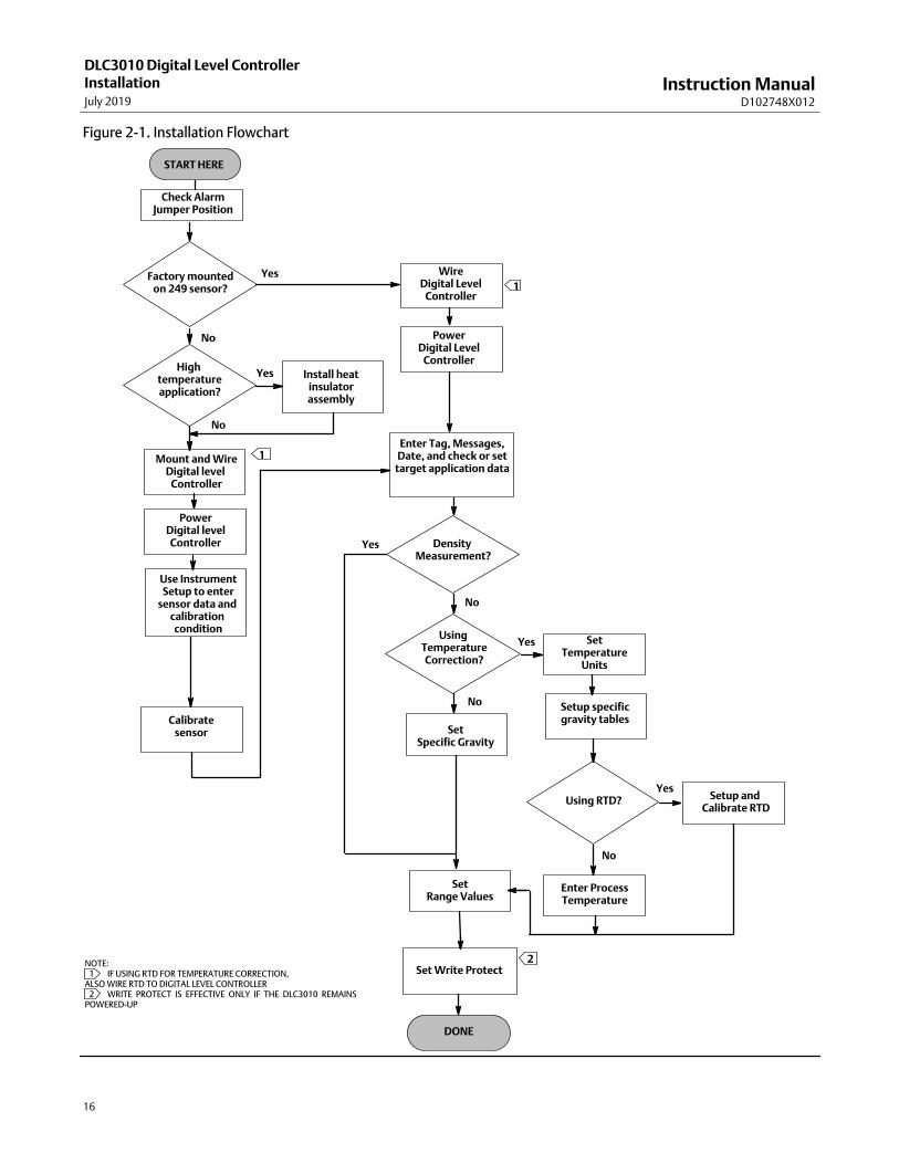
Section 2 Installation2-2-This section contains digital level controller installation information including an installation flowchart (figure 2‐1),mounting and electrical installation information, and a discussion of failure mode jumpers.
Configuration: On the Bench or in the LoopConfigure the digital level controller before or after installation. It may be useful to configure the instrument on thebench before installation to ensure proper operation, and to familiarize yourself with its functionality.
Protecting the Coupling and Flexures
CAUTION
Damage to flexures and other parts can cause measurement errors. Observe the following steps before moving the sensorand controller.
Lever LockThe lever lock is built in to the coupling access handle. When the handle is open, it positions the lever in the neutraltravel position for coupling. In some cases, this function is used to protect the lever assembly from violent motionduring shipment.
A DLC3010 controller will have one of the following mechanical configurations when received:
1. A fully assembled and coupled caged‐displacer system shipped with the displacer or driver rod blocked within theoperating range by mechanical means. In this case, the access handle (figure 2‐4) will be in the unlocked position.Remove the displacer‐blocking hardware before calibration. (See the appropriate sensor instruction manual). Thecoupling should be intact.
CAUTION
When shipping an instrument mounted on a sensor, if the lever assembly is coupled to the linkage, and the linkage isconstrained by the displacer blocks, use of the lever lock may result in damage to bellows joints or flexure.
2. If the displacer cannot be blocked because of cage configuration or other concerns, the transmitter is uncoupledfrom the torque tube by loosening the coupling nut, and the access handle will be in the locked position. Beforeplacing such a configuration into service, perform the Coupling procedure found on page 39.
3. For a cageless system where the displacer is not connected to the torque tube during shipping, the torque tubeitself stabilizes the coupled lever position by resting against a physical stop in the sensor. The access handle will bein the unlocked position. Mount the sensor and hang the displacer. The coupling should be intact.
Instruction ManualD102748X012
DLC3010 Digital Level ControllerInstallationJuly 2019
16
Figure 2‐1. Installation Flowchart
START HERE
Factory mountedon 249 sensor?
Use InstrumentSetup to enter
sensor data and calibration condition
Check AlarmJumper Position
Mount and WireDigital level
Controller
PowerDigital levelController
No
Yes
Install heatinsulatorassembly
High temperatureapplication?
Yes
No
Calibratesensor
WireDigital Level
Controller
PowerDigital Level
Controller
Enter Tag, Messages,Date, and check or set
target application data
Density Measurement?
SetRange Values
Using TemperatureCorrection?
SetTemperature
Units
Setup specificgravity tables
SetSpecific Gravity
Yes
No
Yes
No
Using RTD?Yes
Setup and Calibrate RTD
Enter ProcessTemperature
No
1
1
DONE
Set Write ProtectNOTE: 1 �IF USING RTD FOR TEMPERATURE CORRECTION,ALSO WIRE RTD TO DIGITAL LEVEL CONTROLLER 2 �WRITE PROTECT IS EFFECTIVE ONLY IF THE DLC3010 REMAINSPOWERED‐UP
2

Instruction ManualD102748X012
DLC3010 Digital Level ControllerInstallation
July 2019
17
4. If the controller was shipped alone, the access handle will be in the locked position. All Mounting, Coupling andCalibration procedures must be performed.
The access handle includes a retaining set screw, as shown in figures 2‐4 and 2‐6. The screw is driven in to contact thespring plate in the handle assembly before shipping. It secures the handle in the desired position during shipping andoperation. To set the access handle in the open or closed position, this set screw must be backed out so that its top isflush with the handle surface.
Mounting
WARNING
To avoid personal injury, always wear protective gloves, clothing, and eyewear when performing any installationoperations.
Personal injury or property damage due to sudden release of pressure, contact with hazardous fluid, fire, or explosion canbe caused by puncturing, heating, or repairing a displacer that is retaining process pressure or fluid. This danger may notbe readily apparent when disassembling the sensor or removing the displacer. Before disassembling the sensor orremoving the displacer, observe the appropriate warnings provided in the sensor instruction manual.
Check with your process or safety engineer for any additional measures that must be taken to protect against processmedia.
Hazardous Area Classifications and Special Instructions for “Safe Use” andInstallations in Hazardous LocationsRefer to the DLC3010 Quick Start Guide (D103214X012) that ships with the instrument for Hazardous AreaClassifications and Special Instructions for “Safe Use” and Installations in Hazardous Locations. If a copy of this quickstart guide is needed contact your Emerson sales office or go to Fisher.com.
Mounting the 249 Sensor The 249 sensor is mounted using one of two methods, depending on the specific type of sensor. If the sensor has acaged displacer, it typically mounts on the side of the vessel as shown in figure 2‐2. If the sensor has a cagelessdisplacer, the sensor mounts on the side or top of the vessel as shown in figure 2‐3.
The DLC3010 digital level controller is typically shipped attached to the sensor. If ordered separately, it may beconvenient to mount the digital level controller to the sensor and perform the initial setup and calibration beforeinstalling the sensor on the vessel.
Note
Caged sensors have a rod and block installed on each end of the displacer to protect the displacer in shipping. Remove these partsbefore installing the sensor to allow the displacer to function properly.

Instruction ManualD102748X012
DLC3010 Digital Level ControllerInstallationJuly 2019
18
Figure 2‐2. Typical Caged Sensor Mounting Figure 2‐3. Typical Cageless Sensor Mounting
Digital Level Controller OrientationMount the digital level controller with the torque tube shaft clamp access hole (see figure 2‐4) pointing downward toallow accumulated moisture drainage.
Figure 2‐4. Sensor Connection Compartment (Adapter Ring Removed for Clarity)
PRESS HERE TOMOVE ACCESSHANDLE
SLIDE ACCESS HANDLETOWARD FRONT OF UNITTO EXPOSE ACCESS HOLE
ACCESSHOLE
MOUNTINGSTUDS
SHAFT CLAMP
SET SCREW

Instruction ManualD102748X012
DLC3010 Digital Level ControllerInstallation
July 2019
19
Note
If alternate drainage is provided by the user, and a small performance loss is acceptable, the instrument could be mounted in 90degree rotational increments around the pilot shaft axis. The LCD meter may be rotated in 90 degree increments to accommodatethis.
The digital level controller and torque tube arm are attached to the sensor either to the left or right of the displacer, asshown in figure 2‐5. This can be changed in the field on the 249 sensors (refer to the appropriate sensor instructionmanual). Changing the mounting also changes the effective action, because the torque tube rotation for increasinglevel, (looking at the protruding shaft), is clockwise when the unit is mounted to the right of the displacer and counter‐clockwise when the unit is mounted to the left of the displacer.
All caged 249 sensors have a rotatable head. That is, the digital level controller can be positioned at any of eightalternate positions around the cage as indicated by the position numbers 1 through 8 in figure 2‐5. To rotate the head,remove the head flange bolts and nuts and position the head as desired.
Figure 2‐5. Typical Mounting Positions for the FIELDVUE DLC3010 Digital Level Controller on Fisher 249 Sensor
8
24
6
3
7
1
5
SENSOR
CAGED
CAGELESS
RIGHT-OF-DISPLACERLEFT-OF-DISPLACER
1
1� Not available for 249C and 249K.
8
24
6
1
3
7
5 1

Instruction ManualD102748X012
DLC3010 Digital Level ControllerInstallationJuly 2019
20
Mounting the Digital Level Controller on a 249 Sensor Refer to figure 2‐4 unless otherwise indicated.
1. If the set‐screw in the access handle (figure 2‐6) is driven against the spring plate, back it out until the head is flushwith the outer surface of the handle, using a 2 mm hex key. Slide the access handle to the locked position to exposethe access hole. Press on the back of the handle as shown in figure 2‐4 then slide the handle toward the front of theunit. Be sure the locking handle drops into the detent.
Figure 2‐6. Close‐up of Set‐Screw
SET‐SCREW
2. Using a 10 mm deep well socket inserted through the access hole, loosen the shaft clamp (figure 2‐4). This clampwill be re‐tightened in the Coupling portion of the Initial Setup section.
3. Remove the hex nuts from the mounting studs. Do not remove the adapter ring.
CAUTION
Measurement errors can occur if the torque tube assembly is bent or misaligned during installation.
4. Position the digital level controller so the access hole is on the bottom of the instrument.
5. Carefully slide the mounting studs into the sensor mounting holes until the digital level controller is snug againstthe sensor.
6. Reinstall the hex nuts on the mounting studs and tighten the hex nuts to 10 N�m (88.5 lbf�in).
Mounting the Digital Level Controller for High Temperature Applications Refer to figure 2‐8 for parts identification except where otherwise indicated.
The digital level controller requires an insulator assembly when temperatures exceed the limits shown in figure 2‐7.
A torque tube shaft extension is required for a 249 sensor when using an insulator assembly.
CAUTION
Measurement errors can occur if the torque tube assembly is bent or misaligned during installation.

Instruction ManualD102748X012
DLC3010 Digital Level ControllerInstallation
July 2019
21
Figure 2‐7. Guidelines for Use of Optional Heat Insulator Assembly
HEAT INSULATORREQUIRED
70
0 20 40 60 80 100 120 140 160
0 10 20-20 -10 30 40 50 60
400
300
200
100
00
400
800
-325
AMBIENT TEMPERATURE (�C)
STANDARD TRANSMITTER
AMBIENT TEMPERATURE (�F)
HEAT INSULATORREQUIRED
TOOHOT
NOTES: 1 �FOR PROCESS TEMPERATURES BELOW -29�C (-20�F) AND ABOVE 204�C (400�F) SENSOR MATERIALS MUST BE APPROPRIATE FOR THE PROCESS; SEE TABLE 1‐4.2. IF AMBIENT DEW POINT IS ABOVE PROCESS TEMPERATURE, ICE FORMATION MIGHT CAUSE INSTRUMENT MALFUNCTION AND REDUCE INSULATOR EFFECTIVENESS.
39A4070‐BA5494‐1
42580
-100
-200
176-20-40
-40 -30
TOOCOLD
1
NO HEAT INSULATOR NECESSARY
PR
OC
ES
S T
EM
PE
RA
TU
RE
(�
F)
PR
OC
ES
S T
EM
PE
RA
TU
RE
(�
C)
Figure 2‐8. Digital Level Controller Mounting on Sensor in High Temperature Applications
MN2880020A7423‐CB2707
SENSOR DIGITAL LEVEL CONTROLLER
SHAFTEXTENSION(KEY 58)
SHAFTCOUPLING(KEY 59)
SET SCREWS(KEY 60)
INSULATOR(KEY 57)
CAP SCREWS(KEY 63)
MOUNTING STUDS(KEY 33)
HEX NUTS(KEY 34)
WASHER(KEY 78)
1. For mounting a digital level controller on a 249 sensor, secure the shaft extension to the sensor torque tube shaftvia the shaft coupling and set screws, with the coupling centered as shown in figure 2‐8.
2. Slide the access handle to the locked position to expose the access hole. Press on the back of the handle as shown infigure 2‐4 then slide the handle toward the front of the unit. Be sure the locking handle drops into the detent.
3. Remove the hex nuts from the mounting studs.
4. Position the insulator on the digital level controller, sliding the insulator straight over the mounting studs.
5. Install 4 washers (key 78) over the studs. Install the four hex nuts and tighten.
6. Carefully slide the digital level controller with the attached insulator over the shaft coupling so that the access holeis on the bottom of the digital level controller.
7. Secure the digital level controller and insulator to the torque tube arm with four cap screws.
8. Tighten the cap screws to 10 N�m (88.5 lbf�in).
Instruction ManualD102748X012
DLC3010 Digital Level ControllerInstallationJuly 2019
22
Electrical Connections
WARNING
Select wiring and/or cable glands that are rated for the environment of use (such as hazardous area, ingress protection andtemperature). Failure to use properly rated wiring and/or cable glands can result in personal injury or property damagefrom fire or explosion.
Wiring connections must be in accordance with local, regional, and national codes for any given hazardous area approval.Failure to follow the local, regional, and national codes could result in personal injury or property damage from fire orexplosion.
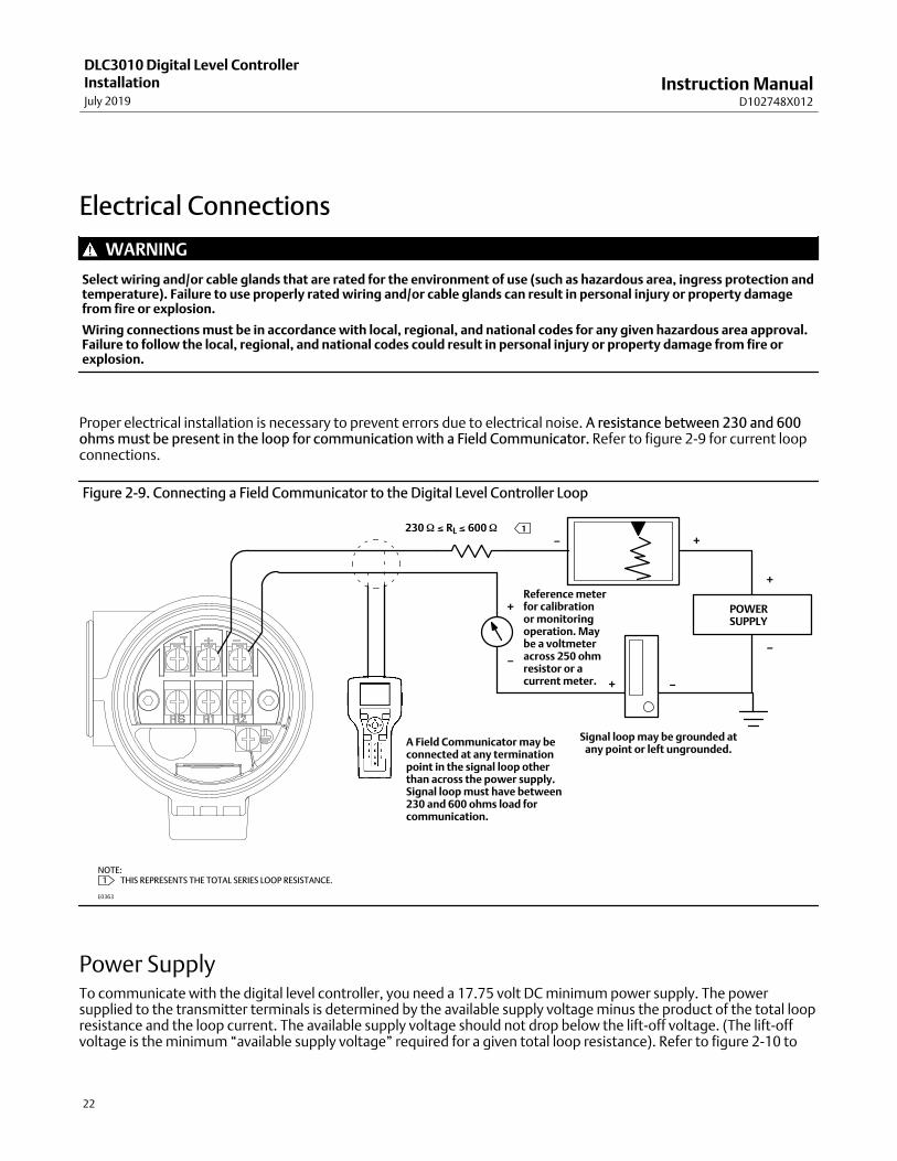
Proper electrical installation is necessary to prevent errors due to electrical noise. A resistance between 230 and 600ohms must be present in the loop for communication with a Field Communicator. Refer to figure 2‐9 for current loopconnections.
Figure 2‐9. Connecting a Field Communicator to the Digital Level Controller Loop
230 � � RL � 600 �
POWERSUPPLY
Signal loop may be grounded atany point or left ungrounded.
A Field Communicator may beconnected at any terminationpoint in the signal loop otherthan across the power supply.Signal loop must have between230 and 600 ohms load forcommunication.
Reference meterfor calibrationor monitoringoperation. Maybe a voltmeteracross 250 ohmresistor or acurrent meter.
E0363
1
NOTE: 1 �THIS REPRESENTS THE TOTAL SERIES LOOP RESISTANCE.
+
+
+
+
−
−
−
−
Power Supply To communicate with the digital level controller, you need a 17.75 volt DC minimum power supply. The powersupplied to the transmitter terminals is determined by the available supply voltage minus the product of the total loopresistance and the loop current. The available supply voltage should not drop below the lift‐off voltage. (The lift‐offvoltage is the minimum “available supply voltage” required for a given total loop resistance). Refer to figure 2‐10 to

Instruction ManualD102748X012
DLC3010 Digital Level ControllerInstallation
July 2019
23
determine the required lift‐off voltage. If you know your total loop resistance you can determine the lift‐off voltage. Ifyou know the available supply voltage, you can determine the maximum allowable loop resistance.
Figure 2‐10. Power Supply Requirements and Load Resistance
Maximum Load = 43.5 X (Available Supply Voltage - 12.0)
12 30
LIFT‐OFF SUPPLY VOLTAGE (VDC)
Loa
d (
Oh
ms)
0
10 20 2515
783
250
OperatingRegion
If the power supply voltage drops below the lift‐off voltage while the transmitter is being configured, the transmittermay output incorrect information.
The DC power supply should provide power with less than 2% ripple. The total resistance load is the sum of theresistance of the signal leads and the load resistance of any controller, indicator, or related pieces of equipment in theloop. Note that the resistance of intrinsic safety barriers, if used, must be included.
Field Wiring
Note
For intrinsically safe applications, refer to the instructions supplied by the barrier manufacturer.
WARNING
To avoid personal injury or property damage caused by fire or explosion, remove power to the instrument before removingthe digital level controller cover in an area which contains a potentially explosive atmosphere or has been classified ashazardous.
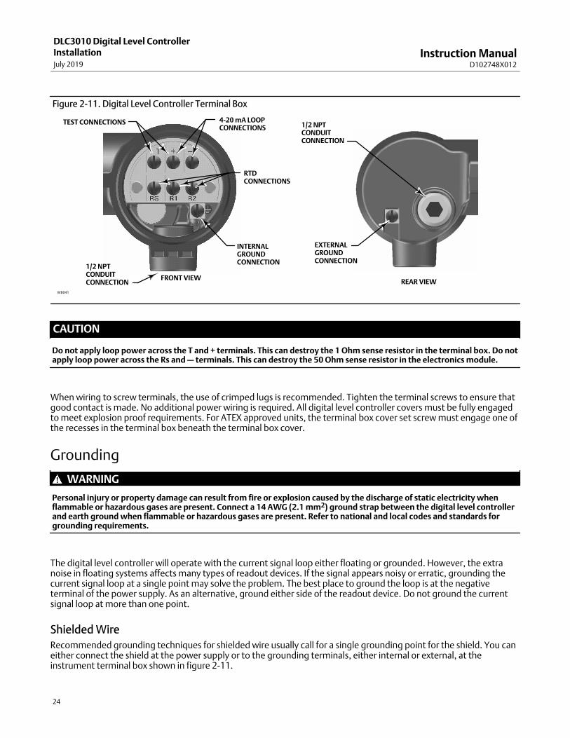
All power to the digital level controller is supplied over the signal wiring. Signal wiring need not be shielded, but usetwisted pairs for best results. Do not run unshielded signal wiring in conduit or open trays with power wiring, or nearheavy electrical equipment. If the digital controller is in an explosive atmosphere, do not remove the digital levelcontroller covers when the circuit is alive, unless in an intrinsically safe installation. Avoid contact with leads andterminals. To power the digital level controller, connect the positive power lead to the + terminal and the negativepower lead to the - terminal as shown in figure 2‐11.
Instruction ManualD102748X012
DLC3010 Digital Level ControllerInstallationJuly 2019
24
Figure 2‐11. Digital Level Controller Terminal Box
4‐20 mA LOOPCONNECTIONS
TEST CONNECTIONS
INTERNALGROUNDCONNECTION
1/2 NPT CONDUIT CONNECTION
FRONT VIEWREAR VIEW
RTDCONNECTIONS
W8041
EXTERNALGROUNDCONNECTION
1/2 NPT CONDUIT CONNECTION
CAUTION
Do not apply loop power across the T and + terminals. This can destroy the 1 Ohm sense resistor in the terminal box. Do notapply loop power across the Rs and — terminals. This can destroy the 50 Ohm sense resistor in the electronics module.
When wiring to screw terminals, the use of crimped lugs is recommended. Tighten the terminal screws to ensure thatgood contact is made. No additional power wiring is required. All digital level controller covers must be fully engagedto meet explosion proof requirements. For ATEX approved units, the terminal box cover set screw must engage one ofthe recesses in the terminal box beneath the terminal box cover.
Grounding
WARNING
Personal injury or property damage can result from fire or explosion caused by the discharge of static electricity whenflammable or hazardous gases are present. Connect a 14 AWG (2.1 mm2) ground strap between the digital level controllerand earth ground when flammable or hazardous gases are present. Refer to national and local codes and standards forgrounding requirements.
The digital level controller will operate with the current signal loop either floating or grounded. However, the extranoise in floating systems affects many types of readout devices. If the signal appears noisy or erratic, grounding thecurrent signal loop at a single point may solve the problem. The best place to ground the loop is at the negativeterminal of the power supply. As an alternative, ground either side of the readout device. Do not ground the currentsignal loop at more than one point.
Shielded Wire
Recommended grounding techniques for shielded wire usually call for a single grounding point for the shield. You caneither connect the shield at the power supply or to the grounding terminals, either internal or external, at theinstrument terminal box shown in figure 2‐11.

Instruction ManualD102748X012
DLC3010 Digital Level ControllerInstallation
July 2019
25
Power/Current Loop Connections Use ordinary copper wire of sufficient size to ensure that the voltage across the digital level controller terminals doesnot go below 12.0 volts DC. Connect the current signal leads as shown in figure 2‐9. After making connections,recheck the polarity and correctness of connections, then turn the power on.
RTD ConnectionsAn RTD that senses process temperatures may be connected to the digital level controller. This permits the instrumentto automatically make specific gravity corrections for temperature changes. For best results, locate the RTD as close tothe displacer as practical. For optimum EMC performance, use shielded wire no longer than 3 meters (9.8 feet) toconnect the RTD. Connect only one end of the shield. Connect the shield to either the internal ground connection inthe instrument terminal box or to the RTD thermowell. Wire the RTD to the digital level controller as follows (refer tofigure 2‐11):
Two‐Wire RTD Connections1. Connect a jumper wire between the RS and R1 terminals in the terminal box.
2. Connect the RTD to the R1 and R2 terminals.
Note
During Manual Setup, you must specify the connecting wire resistance for a 2‐wire RTD. 250 feet of 16 AWG wire has a resistance
of 1 ohm.
Three‐Wire RTD Connections1. Connect the 2 wires which are connected to the same end of the RTD to the RS and R1 terminals in the terminal
box. Usually these wires are the same color.
2. Connect the third wire to terminal R2. (The resistance measured between this wire and either wire connected toterminal RS or R1 should read an equivalent resistance for the existing ambient temperature. Refer to the RTDmanufacturer's temperature to resistance conversion table.) Usually this wire is a different color from the wiresconnected to the RS and R1 terminals.
Communication Connections
WARNING
Personal injury or property damage caused by fire or explosion may occur if this connection is attempted in an area whichcontains a potentially explosive atmosphere or has been classified as hazardous. Confirm that area classification andatmosphere conditions permit the safe removal of the terminal box cap before proceeding.
The Field Communicator interfaces with digital level controller from any wiring termination point in the 4–20 mA loop(except across the power supply). If you choose to connect the HART communicating device directly to theinstrument, attach the device to the loop + and - terminals inside the terminal box to provide local communicationswith the instrument.
Instruction ManualD102748X012
DLC3010 Digital Level ControllerInstallationJuly 2019
26
Test Connections
WARNING
Personal injury or property damage caused by fire or explosion may occur if the following procedure is attempted in anarea which contains a potentially explosive atmosphere or has been classified as hazardous. Confirm that area classificationand atmosphere conditions permit the safe removal of the terminal box cap before proceeding.
Test connections inside the terminal box can be used to measure loop current across an internal 1 ohm resistor.
1. Remove the terminal box cap.
2. Adjust the test meter to measure a range of 0.001 to 0.1 volts.
3. Connect the positive lead of the test meter to the + connection and the negative lead to the T connection inside theterminal box.
4. Measure Loop current as:
Voltage (on test meter) � 1000 = milliamps
example:
Test meter Voltage X 1000 = Loop Milliamps
0.004 X1000 = 4.0 milliamperes
0.020 X 1000 = 20.0 milliamperes
5. Remove test leads and replace the terminal box cover.
Multichannel Installations You can connect several instruments to a single master power supply as shown in figure 2‐12. In this case, the systemmay be grounded only at the negative power supply terminal. In multichannel installations where several instrumentsdepend on one power supply, and the loss of all instruments would cause operational problems, consider anuninterruptible power supply or a back‐up battery. The diodes shown in figure 2‐12 prevent unwanted charging ordischarging of the back‐up battery. If several loops are connected in parallel, make sure the net loop impedance doesnot reach levels that would prevent communication.

Instruction ManualD102748X012
DLC3010 Digital Level ControllerInstallation
July 2019
27
Figure 2‐12. Multichannel Installations
RLead
RLead
RLead
+
+
-
-
To Additional InstrumentsBetween
230 and 600 �if no Load Resistor
InstrumentNo. 2
+
-
InstrumentNo. 1
ReadoutDevice No. 2
ReadoutDevice No. 1
DC PowerSupply
+
-
E0364
BatteryBackup
+
-
RLead
Note that to provide a 4‐20 mA analog output signal, the DLC3010 must use HART polling address 0. Therefore, if amultichannel installation is used with all transmitters in 4‐20 mA output mode, some means must be provided toisolate an individual transmitter for configuration or diagnostic purposes. A multichannel installation is most useful ifthe instruments are also in multi‐drop mode and all signaling is done by digital polling.
Alarm Jumper Each digital level controller continuously monitors its own performance during normal operation. This automaticdiagnostic routine is a timed series of checks repeated continuously. If diagnostics detect a failure in the electronics,the instrument drives its output to either below 3.70 mA or above 22.5 mA, depending on the position (HI/LO) of thealarm jumper.
An alarm condition occurs when the digital level controller self‐diagnostics detect an error that would render theprocess variable measurement inaccurate, incorrect, or undefined, while a HiHi or LoLo PV monitor is enabled. At thispoint the analog output of the unit is driven to a defined level either above or below the nominal 4‐20 mA range, basedon the position of the alarm jumper.
On encapsulated electronics 14B5483X042 and earlier, if the jumper is missing, the alarm is indeterminate, but usuallybehaves as a FAIL LOW selection. On encapsulated electronics 14B5483X052 and later, the behavior will default toFAIL HIGH when the jumper is missing.
Alarm Jumper Locations
Without a meter installed
The alarm jumper is located on the front side of the electronics module on the electronics side of the digital levelcontroller housing, and is labeled FAIL MODE.
With a meter installed
The alarm jumper is located on the LCD faceplate on the electronics module side of the digital level controller housing,and is labeled FAIL MODE.
Instruction ManualD102748X012
DLC3010 Digital Level ControllerInstallationJuly 2019
28
Changing Jumper Position
WARNING
Personal injury or property damage caused by fire or explosion may occur if the following procedure is attempted in anarea which contains a potentially explosive atmosphere or has been classified as hazardous. Confirm that area classificationand atmosphere conditions permit the safe removal of the instrument cover before proceeding.
Use the following procedure to change the position of the alarm jumper:
1. If the digital level controller is installed, set the loop to manual.
2. Remove the housing cover on the electronics side. Do not remove the cover in explosive atmospheres when thecircuit is alive.
3. Set the jumper to the desired position.
4. Replace the cover. All covers must be fully engaged to meet explosion proof requirements. For ATEX approvedunits, the set screw on the transducer housing must engage one of the recesses in the cover.
Loop Test Field Communicator Service Tools > Maintenance > Tests > Loop Test (3-4-1-2)
Loop test can be used to verify the controller output, the integrity of the loop, and the operations of any recorders orsimilar devices installed in the loop. To initiate a loop test, perform the following procedure:
1. Connect a reference meter to the controller. To do so, either connect the meter to the test connections inside theterminal box (see the Test Connections procedure) or connect the meter in the loop as shown in figure 2‐9.
2. Access Loop Test.
3. Select OK after you set the control loop to manual.
The Field Communicator displays the loop test menu.
4. Select a discreet milliamp level for the controller to output. At the “Choose analog output” prompt, select 4 mA, 20 mA, or Other to manually input a value between 4 and 20 milliamps.
5. Check the reference meter to verify that it reads the value you commanded the controller to output. If the readingsdo not match, either the controller requires an output trim, or the meter is malfunctioning.
After completing the test procedure, the display returns to the loop test screen and allows you to choose anotheroutput value or end the test.

Instruction ManualD102748X012
DLC3010 Digital Level ControllerInstallation
July 2019
29
Installation in Conjunction with a Rosemount 333 HART Tri‐LoopHART‐to‐Analog Signal Converter Use the DLC3010 digital level controller in operation with a Rosemount 333 HART Tri-Loop HART‐to‐Analog SignalConverter to acquire an independent 4‐20 mA analog output signal for the process variable, % range, electronicstemperature, and process temperature. The Tri‐Loop divides the digital signal and outputs any or all of these variablesinto as many as three separate 4‐20 mA analog channels.
Refer to figure 2‐13 for basic installation information. Refer to the 333 HART Tri‐Loop HART‐to‐Analog SignalConverter Product Manual (00809-0100-4754) for complete installation information.
Figure 2‐13. HART Tri‐Loop Installation Flowchart
START HERE
DONE
Digital levelcontrollerInstalled?
Unpack theHART Tri‐Loop
Review theHART Tri‐Loop
Product Manual
Set the digitallevel controller
Burst Option
Set the digitallevel controller
Burst Mode
No
Yes
Install the digitallevel controller.
Install the HARTTri‐Loop. See
HART Tri‐LoopProduct Manual
Mount the HARTTri‐Loop to the
DIN rail.
Wire the digitallevel controller to
the HART Tri‐Loop.
Install Channel 1wires from HART
Tri‐Loop to thecontrol room.
(Optional)Install Channel
2 and3 wires fromHART Tri‐Loop to the control room.
Configure the HARTTri‐Loop to receive
digital level controllerburst commands
Pass systemtest?
Checktroubleshooting
procedures in HARTTri‐Loop product
manual.
No
Yes
E0365

Instruction ManualD102748X012
DLC3010 Digital Level ControllerInstallationJuly 2019
30
Commissioning the Digital Level Controller for use with the HART Tri‐LoopTo prepare the digital level controller for use with a 333 HART Tri‐Loop, you must configure the digital level controllerto burst mode, and select the dynamic variables to burst. In burst mode, the digital level controller provides digitalinformation to the HART Tri‐Loop HART‐to‐Analog Signal Converter. The HART Tri‐Loop converts the digitalinformation to a 4‐20 mA analog signal. The HART Tri‐Loop divides the signal into separate 4‐20 mA loops for theprimary (PV), secondary (SV), and tertiary (TV) variables. Depending upon the burst option selected, the digital levelcontroller will burst the variables as shown in table 2‐1.
The DLC3010 status words are available in the HART Burst messages. However, the Tri‐Loop cannot be configured tomonitor them directly.
To commission a DLC3010 digital level controller for use with a HART Tri‐Loop, perform the following procedure.
Table 2‐1. Burst Variables Sent by the FIELDVUE DLC3010Burst Option Variable Variable Burst(1) Burst Command
Read PV Primary Process variable (EU) 1
Read PV mA and % RangeLoop Current Process variable (mA)
2Percent Range Process variable Percent range (%)
Read Dynamic Vars
Loop Current Process variable (mA)
3
Primary Process variable (EU)
Secondary Electronics temperature (EU)
Tertiary Process temperature (EU)
Quaternary Not used
1. EU—engineering units; mA—current in milliamperes; %—percent of span
Set the Burst Operation
Field Communicator Configure > Manual Setup > Communications (2-2-6)
1. Access Burst Option.
2. Select the desired burst option and press ENTER
3. Access Burst Mode and select On to enable burst mode. Press ENTER.
4. Select SEND to download the new configuration information to the digital level controller.
Instruction ManualD102748X012
DLC3010 Digital Level ControllerOverview
July 2019
31
Section 3 Overview3-3-
OverviewField Communicator Overview (1)
Device Status
Good There are no active alerts and instrument is In Service.
Failed The highest severity active alert is in the Failed category.
Maintenance The highest severity active alert is in the Maintenance category.
Advisory The highest severity active alert is in the Advisory category.
Comm Status
Polled Communication with digital level controller is established. Burst mode is turned off.
Burst Provides continuous communication from the digital level controller. Burst mode applies only to thetransmission of burst mode data and does not affect the way other data is accessed.
Liquid Level, Interface Level, orLiquid Density
Indicates the type of measurement either level, interface (the interface of two liquids of different specific gravities), ordensity (measures the liquid specific gravity). The process variable displayed and measured depends on the entry for“PV is” under PV Setup.
Process Temperature
When the process temperature is manually entered, indicates the target process temperature entered in the deviceconfiguration.
When the process temperature is NOT manually entered, process temperature represents the temperature measuredby an RTD located in the process fluid.
Analog Output
Indicates the current value for the analog output of the instrument being commanded by the firmware, inmilliamperes.
Calibration / Ranging
Primary
See the Calibration section, starting on page 58, for Primary calibration information.
Instruction ManualD102748X012
DLC3010 Digital Level ControllerOverviewJuly 2019
32
Secondary
See the Calibration section, starting on page 58, for Secondary calibration information.
Ranging
� Upper Sensor Limit indicates the maximum usable value for a Range Value.
� Lower Sensor Limit indicates the minimum usable value for a Range Value.
� Minimum Span is the difference between the Upper Range Value and the Lower Range Value below whichamplification of instrument errors may become a concern. This effect should be considered when sizing displacer /torque tube.
� Upper Range Value defines the operational end point from which the Analog Value and the 100% point of thepercent range are derived.
� Lower Range Value defines the operational end point from which the Analog Value and the 0% point of the percentrange are derived.
� Analog Output Action is set to DIRECT when analog output increases with increasing process signal, and to REVERSEwhen analog output decreases with increasing process signal.
� Change Action allows you to change the output action by swapping values of the Upper Range Value and LowerRange Value. Action is DIRECT if the Upper Range Value is greater than the lower range value. Action is REVERSE ifLower Range Value is greater than Upper Range Value.
� Level Offset is the Primary Variable value you want the instrument to report when physical level is at the bottom ofdisplacer. It is only available in Level or Interface measurement mode.
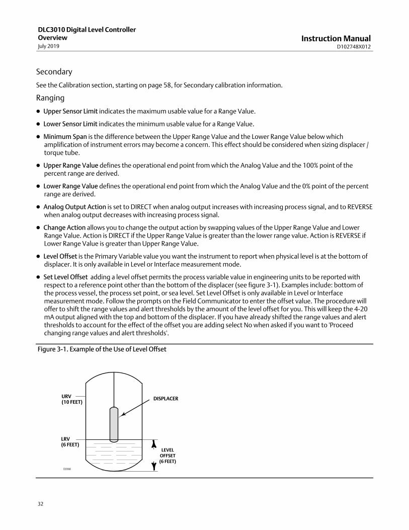
� Set Level Offset adding a level offset permits the process variable value in engineering units to be reported withrespect to a reference point other than the bottom of the displacer (see figure 3‐1). Examples include: bottom ofthe process vessel, the process set point, or sea level. Set Level Offset is only available in Level or Interfacemeasurement mode. Follow the prompts on the Field Communicator to enter the offset value. The procedure willoffer to shift the range values and alert thresholds by the amount of the level offset for you. This will keep the 4-20mA output aligned with the top and bottom of the displacer. If you have already shifted the range values and alertthresholds to account for the effect of the offset you are adding select No when asked if you want to 'Proceedchanging range values and alert thresholds'.
Figure 3‐1. Example of the Use of Level Offset
LEVELOFFSET(6 FEET)
URV(10 FEET)
LRV(6 FEET)
E0368
DISPLACER

Instruction ManualD102748X012
DLC3010 Digital Level ControllerOverview
July 2019
33
Device Information
Identification
Follow the prompts on the Field Communicator display to view the following information.
� Tag (also called HART tag) is a unique name (up to eight characters) that identifies the physical instrument.
� Distributor identifies the distributor of the instrument.
� Model identifies the instrument model; ie. DLC3010.
� Serial Numbers
Device ID— each instrument has a unique Device Identifier. The Device ID provides additional security to preventthis instrument from accepting commands meant for other instruments.
Instrument Serial Number— enter or view the serial number on the instrument nameplate, up to 12 characters.
Sensor Serial Number— enter or view the sensor serial number. The sensor serial number is found on the sensornameplate.
Final Assembly Number— a number that can be used to identify the instrument and sensor combination.
� Date is a userdefined variable that provides a place to save the date of the last revision of configuration orcalibration information.
� Description is a longer userdefined electronic label to assist with more specific controller identification than isavailable with the HART tag.
� Message is a user‐defined means for identifying individual controllers in multi‐controller environments.
Revisions
Follow the prompts on the Field Communicator display to view revision information.
� Universal indicates the revision number of the HART Universal Commands which are used as the communicationsprotocol for the instrument.
� Device indicates the revision of the external interface specification that governs communication between the FieldCommunicator and the instrument.
� Firmware indicates the revision number of the Fisher software in the instrument.
� Hardware indicates the revision number of the Fisher instrument hardware.
� DD Information is the revision level of the Device Description used by the Field Communicator whilecommunicating with the instrument.

Instruction ManualD102748X012
DLC3010 Digital Level ControllerOverviewJuly 2019
34
Alarm Type and Security
� Alarm Configuration
Alarm Jumper indicates the analog output commanded in an alarm condition, either Fail Lo (3.7 mA) or Fail Hi (22.5 mA).
Notes
Consider the effect of an alarm annunciation on the process and set alarm jumper position accordingly.
When Output Action is 'Direct':�A Hi alarm setting will result in an alarm-state output consistent with a very high process.�A Lo alarm setting will result in an alarm-state output consistent with a very low process.
When Output Action is 'Reverse', these relationships are swapped.
This variable is not updated dynamically, Select Refresh Jumper if you have moved the jumper.
If the network is in Multi-Drop alarm annunciation is disabled and the device is not directly driving any effector, so jumper setting isnot a concern.
Refresh Jumper allows you read the alarm jumper position.
Signal Levels displays the signal saturation or alarm conditions via Analog Output.
� Security
To setup and calibrate the instrument, Write Protect must be set to Not Write Protected. (Write protection is reset by apower cycle. If you have just powered up the instrument Writes will be enabled by default.) In AMS, go to DeviceInformation in the Overview page. Select the Alarm Type and Security tab to change Write Protect.
Write Protect displays the protection setting; “Not Write Protected” allows configuration and calibration of theinstrument, “Write Protected” indicates that configuration and calibration are not currently allowed.
Change Protection allows you to enable or disable configuration and calibration of the instrument.

Instruction ManualD102748X012
DLC3010 Digital Level ControllerConfiguration
July 2019
35
Section 4 Configuration and Calibration 4-4-
Initial Setup If a DLC3010 digital level controller ships from the factory mounted on a 249 sensor, initial setup and calibration is notnecessary. The factory enters the sensor data, couples the instrument to the sensor, and calibrates the instrument andsensor combination.
Note
If you received the digital level controller mounted on the sensor with the displacer blocked, or if the displacer is not connected,the instrument will be coupled to the sensor and the lever assembly unlocked. To place the unit in service, if the displacer isblocked, remove the rod and block at each end of the displacer and check the instrument calibration. (If the “factory cal” optionwas ordered, the instrument will be precompensated to the process conditions provided on the requisition, and will not appear tobe calibrated if checked against room temperature 0 and 100% water level inputs).
If the displacer is not connected, hang the displacer on the torque tube.
If you received the digital level controller mounted on the sensor and the displacer is not blocked (such as in skid mountedsystems), the instrument will not be coupled, to the sensor, and the lever assembly will be locked. Before placing the unit inservice, couple the instrument to the sensor, then unlock the lever assembly.
When the sensor is properly connected and coupled to the digital level controller, establish the zero process condition and run theappropriate zero calibration procedure under Partial Calibration. The Torque Rate should not need to be re-calibrated.
To review the configuration data entered by the factory, connect the instrument to a 24 VDC power supply as shown infigure 2‐9. Connect the Field Communicator to the instrument and turn it on. Go to Configure and review the dataunder Manual Setup, Alert Setup, and Communications. If your application data has changed since the instrument wasfactory‐configured, refer to the Manual Setup section for instructions on modifying configuration data.
For instruments not mounted on a level sensor or when replacing an instrument, initial setup consists of enteringsensor information. The next step is coupling the sensor to the digital level controller. When the digital level controllerand sensor are coupled, the combination may be calibrated.
Sensor information includes displacer and torque tube information, such as:
� Length units (meters, inches, or centimeters)
� Volume units (cubic inches, cubic millimeters, or milliliters)
� Weight units (kilograms, pounds, or ounce)
� Displacer Length
� Displacer Volume
� Displacer Weight
� Displacer Driver Rod Length (moment arm) (see table 4‐1)

Instruction ManualD102748X012
DLC3010 Digital Level ControllerConfigurationJuly 2019
36
� Torque Tube Material
Note
A sensor with an N05500 torque tube may have NiCu on the nameplate as the torque tube material.
� Instrument mounting (right or left of displacer)
� Measurement Application (level, interface, or density)
Configuration AdviceGuided Setup directs you through initialization of configuration data needed for proper operation. When theinstrument comes out of the box, the default dimensions are set for the most common Fisher 249 construction, so ifany data is unknown, it is generally safe to accept the defaults. The mounting sense 'instrument left or right ofdisplacer' - is important for correct interpretation of positive motion. The torque tube rotation is clockwise with risinglevel when the instrument is mounted to the right of the displacer, and counterclockwise when mounted to the left ofthe displacer. Use Manual Setup to locate and modify individual parameters when they need to be changed.
Preliminary Considerations
Write ProtectField Communicator Overview > Device Information > Alarm Type and Security > Security > Change Protection (1-7-3-2-2)
To setup and calibrate the instrument, Write Protect must be set to Not Write Protected. Write Protect is reset by apower cycle. If you have just powered up the instrument Writes will be enabled by default.
Guided SetupField Communicator Configure > Guided Setup > Instrument Setup (2-1-1)
Note
Place the loop into manual operation before making any changes in setup or calibration.
Instrument Setup is available to aid initial setup. Follow the prompts on the Field Communicator display to enterinformation for the displacer, torque tube, and digital measurement units. Most of the information is available fromthe sensor nameplate, shown in figure 4‐1. The moment arm is the effective length of the driver rod and dependsupon the sensor type. For a 249 sensor, refer to table 4‐1 to determine driver rod length. For a special sensor, refer tofigure 4‐2.

Instruction ManualD102748X012
DLC3010 Digital Level ControllerConfiguration
July 2019
37
Figure 4‐1. Example Sensor Nameplate
DISPLACERPRESSURE RATING
1500 PSI
103 CU‐IN
316 SST
249B
76543210
PSI
2 x 32 INCHES
4 3/4 LBS
K MONEL/STD
285/100 F
WCB STL
MONEL
DISPLACERMATERIAL
DISPLACERVOLUME
DISPLACER SIZE(DIAMETER X LENGTH)
TORQUE TUBE MATERIAL
SENSOR TYPEDISPLACERWEIGHT
ASSEMBLY PRESSURE RATING
ASSEMBLY MATERIAL
TRIM MATERIAL
23A1725‐E sht 1E0366
Table 4‐1. Moment Arm (Driver Rod) Length(1)
SENSOR TYPE(2)MOMENT ARM
mm Inch
249 203 8.01
249B 203 8.01
249BF 203 8.01
249BP 203 8.01
249C 169 6.64
249CP 169 6.64
249K 267 10.5
249L 229 9.01
249N 267 10.5
249P(CL125-CL600)
203 8.01
249P(CL900-CL2500)
229 9.01
249VS (Special)(1) See serial card See serial card
249VS (Std) 343 13.5
249W 203 8.01
1. Moment arm (driver rod) length is the perpendicular distance between the vertical centerline of the displacer and the horizontal centerline of the torque tube. See figure 4‐2. If you cannotdetermine the driver rod length, contact your Emerson sales office and provide the serial number of the sensor.2. This table applies to sensors with vertical displacers only. For sensor types not listed, or sensors with horizontal displacers, contact your Emerson sales office for the driver rod length. Forother manufacturers' sensors, see the installation instructions for that mounting.
1. Enter displacer length, weight, volume units and values, and driver rod (moment arm) length (in the same unitschosen for displacer length) when prompted.
2. Choose Instrument Mounting (left or right of displacer, refer to figure 2‐5).
3. Choose Torque Tube Material.

Instruction ManualD102748X012
DLC3010 Digital Level ControllerConfigurationJuly 2019
38
4. Select the measurement application (liquid level, interface level, or liquid density).
Note
For interface applications using standard hardware, if the 249 is not installed on a vessel, or if the cage can be isolated, calibratethe instrument with weights, water, or other standard test fluid, in level mode. After calibrating in level mode, the instrument canbe switched to interface mode. Then, enter the actual process fluid specific gravity(s) and range values. For an interfaceapplication with an overweight displacer, see the section of this manual on "Calibration with an Overweight Displacer".
If the 249 sensor is installed and must be calibrated in the actual process fluid(s) at operating conditions, enter the finalmeasurement mode and actual process fluid data now.
Figure 4‐2. Method of Determining Moment Arm from External Measurements
HORIZONTAL CLOF TORQUE TUBE
VERTICAL CL OF DISPLACER MOMENT
ARM LENGTH
VESSEL
a. If you choose “Liquid Level” or “Interface Level,” the default process variable units are set to the same unitschosen for displacer length. You are prompted to key in the level offset. Range values will be initialized based onLevel Offset and displacer size. The default upper range value is set to equal the displacer length and the defaultlower range value is set to zero when the level offset is 0.
b. If you choose “Liquid Density,” the default process variable units are set to “SGU” (Specific Gravity Units). Thedefault upper range value is set to “1.0” and the default lower range value is set to “0.1”.
5. Select the desired output action: Direct or Reverse
Choosing “reverse acting” will swap the default values of the upper and lower range values (the process variable valuesat 20 mA and 4 mA). In a reverse acting instrument, the loop current will decrease as the process variable valueincreases.
6. You are given the opportunity to modify the default value for the process variable engineering units.
7. You are then given the opportunity to edit the default values that were entered for the upper range value (PV Valueat 20 mA) and lower range value (PV Value at 4 mA).
8. The default values of the alarm variables will be set as follows:
Direct‐Acting Instrument(Span = Upper Range Value - Lower Range Value
Alarm Variable Default Alarm Value
Hi‐Hi Alarm Upper Range Value
Hi Alarm 95% span + Lower Range Value
Lo Alarm 5% span + Lower Range Value
Lo‐Lo Alarm Lower Range Value
Reverse‐Acting Instrument(Span = Lower Range Value - Upper Range Value
Alarm Variable Default Alarm Value
Hi‐Hi Alarm Lower Range Value
Hi Alarm 95% span + Upper Range Value
Lo Alarm 5% span + Upper Range Value
Lo‐Lo Alarm Upper Range Value

Instruction ManualD102748X012
DLC3010 Digital Level ControllerConfiguration
July 2019
39
PV alert thresholds are initialized at 100%, 95%, 5% and 0% span.
PV alert deadband is initialized to 0.5% span.
PV alerts are all disabled. Temperature alerts are enabled.
� If Liquid Density mode was chosen, setup is complete.
� If Interface Level or Liquid Level mode was chosen, you are advised that process fluid data must be configured. Youhave the options of entering constant SG values or loading default steam tables during setup, or exiting theprocedure and manually configuring the process data later.
Note
If you are using water or weights for calibration, enter a specific gravity of 1.0 SGU. For other test fluids, enter the specific gravityof the fluid used.
Detailed configuration of the process fluid and temperature compensation is provided in Configure > Manual Setup >Process Conditions > Fluid(s).
Coupling If the digital level controller is not already coupled to the sensor, perform the following procedure to couple the digitallevel controller to the sensor.
1. Slide the access handle to the locked position to expose the access hole. Press on the back of the handle as shown infigure 2‐4 then slide the handle toward the front of the unit. Be sure the locking handle drops into the detent.
2. Set the displacer to the lowest possible process condition, (i.e. lowest water level or minimum specific gravity) orreplace the displacer by the heaviest calibration weight.
Note
Interface or density applications with displacer/torque tube sized for a small total change in specific gravity are designed to beoperated with the displacer always submerged. In these applications, the torque rod is sometimes resting on a stop while thedisplacer is dry. The torque tube does not begin to move until a considerable amount of liquid has covered the displacer. In thiscase, couple with the displacer submerged in the fluid with the lowest density and the highest process temperature condition, orwith an equivalent condition simulated by the calculated weights.
If the sizing of the sensor results in a proportional band greater than 100% (total expected rotational span greater than 4.4degrees), couple the transmitter to the pilot shaft while at the 50% process condition to make maximum use of availabletransmitter travel (�6�). The Capture Zero procedure is still performed at the zero buoyancy (or zero differential buoyancy)condition.
3. Insert a 10 mm deep well socket through the access hole and onto the torque tube shaft clamp nut. Tighten theclamp nut to a maximum torque of 2.1 N�m (18 lbf�in).
4. Slide the access handle to the unlocked position. (Press on the back of the handle as shown in figure 2‐4 then slidethe handle toward the rear of the unit.) Be sure the locking handle drops into the detent.

Instruction ManualD102748X012
DLC3010 Digital Level ControllerConfigurationJuly 2019
40
Manual SetupThe DLC3010 digital level controller has the capability to communicate via the HART protocol. This section describesthe advanced features that can be accessed with the Field Communicator.
Note
Changing setup parameters may require enabling writing to the instrument with the Field Communicator (Overview > DeviceInformation > Alarm Type and Security > Security > Change Protection). Select Not Write Protected to enable writing setup andcalibration data, or select Write Protected to disable writing data. Note that cycling power will clear the write lock condition to “NotWrite Protected”.
SensorField Communicator Configure > Manual Setup > Sensor (2-2-1)
Sensor Units
� Length selects the units of measure for the displacer length (in feet, meters, inches, or centimeters).
� Volume selects the units of measure for the displacer volume (in liters, cubic inches, cubic millimeters, or milliliters).
� Weight selects the units of measure for the displacer weight (in grams, kilograms, pounds, or ounces).
� Torque Rate selects the torque rate units (in lbf‐in per deg—pounds‐force inches per degree rotation; newton‐m perdeg—newton‐meters per degree rotation; or dyne‐cm per deg—dyne-centimeters per degree rotation.
� Temperature selects either degC (degrees centigrade) or degF (degrees Fahrenheit) for the temperature units.
Sensor Dimensions
Dimensions can be found on the sensor name plate as shown in figure 4‐1.
� Displacer Length— Enter the displacer length from the sensor nameplate.
� Displacer Volume— Enter the displacer volume from the sensor nameplate.
� Displacer Weight— Enter the displacer weight from the sensor nameplate.
� Driver Rod Length— Enter the displacer rod length. The displacer rod length depends upon the sensor type. For a249 sensor, obtain the displacer rod length from table 4‐1 or from the Field Communicator Help. Refer to figure 4‐2to physically measure this value.
Instruction ManualD102748X012
DLC3010 Digital Level ControllerConfiguration
July 2019
41
Torque Tube
� TT Material displays the torque tube material currently stored in the instrument.
Note
A sensor with an N05500 torque tube may have NiCu on the nameplate as the torque tube material.
� Change Material— selecting a material in this procedure loads the default torque rate temperature compensationfor the specified torque tube material.
� Edit Compensation
TT Compensation— Each temperature-coefficient data pair may be edited.
If using fewer than 10 data pairs, a “0.0” entry in the dependent variable slot terminates the table entry process. The firmware treats a zero entry in the dependent variable slot as an indication that the previous data point was theend of the table and that interpolation ends at that point. If only one data pair exists before the pair with the 0.0dependent variable entry, the table is flat. It provides a constant output across the entire temperature range.
Torque Comp Plot displays a graph of the compensation table.
Pre-compensate Torque Rate— The stiffness of the torque tube varies with process temperature. The firmwaredoes not implement dynamic temperature compensation of the torque rate. However, the compensation tablesfor this effect are stored in the device. The “Pre-compensate Torque Rate” procedure allows you to apply a fixedcompensation factor, based on the target process temperature, to the torque rate value stored in the instrument. For example, if the sensor was calibrated at 70�F or a theoretical torque rate valid at 70�F was manually entered inthe configuration, but the target process operating condition is 375�F, this procedure will compute an appropriatecorrection factor from the table for the selected torque tube material, and modify the stored torque rate by thatfactor. The calibration should then be more accurate at the target process temperature (with a correspondingdegradation at 70�F). It is recommended that you document this action by entering appropriate text in theDescription and/or Message fields of the device configuration, to facilitate reversing the compensation later, and tohelp prevent it from being applied twice.
� Torque Rate displays the torque rate currently stored in the instrument.
� Change Torque Rate applies a rough, theoretical calibration to the torque tube when manipulation of the input isimpossible
Instrument Mounting
Specify whether the instrument is mounted to the right or left of the displacer. See figure 2‐5.
Note
While facing DLC3010 Display, report whether DLC3010 is mounted to left or right of displacer. This determines positive sense oftorque tube rotation for increasing buoyancy.
Sensor Damping
Configure the input filter.
Time constant for the input filter, in seconds, for the A/D measurement. The filter is applied before PV processing,after the A/D conversion. Range is 0 to 16 seconds in 0.1 second increments. The default value is 0.0 seconds. To
Instruction ManualD102748X012
DLC3010 Digital Level ControllerConfigurationJuly 2019
42
disable the filter, set the time constant to 0 seconds. This filter is provided for extreme input noise situations. Use ofthis filter normally should not be necessary.
Net instrument response is a combination of analog input filtering, sensor damping, PV damping, and output filtering.
VariablesField Communicator Configure > Manual Setup > Variables (2-2-2)
View or edit Variable information.
Primary VariableSecondary VariableThird Variable
� PV, SV or TV display the PV, SV, or TV assignment, as selected, currently stored in the instrument.
� Units— Permits changing the units.
For density measurement:��g/cm3—grams per cubic centimeter��kg/m3—kilograms per cubic meter��lb/gal—pounds per gallon��lb/ft3—pounds per cubic foot��g/mL—grams per milliliter��kg/L—kilograms per liter��g/L—grams per liter��lb/in3—pounds per cubic inch��SGU—specific gravity units
For level and interface measurement:��ft—feet��m—meters��in—inches��cm—centimeters��mm—millimeters
For TV and SV the units are read-only, as they are controlled by the Temperature Units selection in the Sensor Unitsmenu.
� Damping changes the response time of the controller to smooth variations in output readings caused by rapidchanges in input. Determine the appropriate damping setting based on the necessary response time, signalstability, and other requirements of the loop dynamics of your system. The default damping value is 0.2 seconds.and can be reset to any value between 0 and 16 seconds in 0.1 second increments. When set to 0, the dampingfunction is off. Damping for SV and TV is fixed at 60 seconds and is displayed for information only.
Net instrument response is a combination of analog input filtering, sensor damping, PV damping, and outputfiltering.
Instruction ManualD102748X012
DLC3010 Digital Level ControllerConfiguration
July 2019
43
Change PV
Allow you to change the PV assignment. Select Level Units if the PV is level, Interface Units if the PV is Interface, orDensity Units if the PV is Density.
Note
If the PV assignment is changing to Level or Interface, go to the Process Fluid(s) menu and edit the configuration data for fluiddensity before returning the loop to Auto.
RangingField Communicator Configure > Manual Setup > Ranging (2-2-3)
Follow the prompts on the Field Communicator to view or edit ranging information.
� Upper Sensor Limit indicates the maximum usable value for a Range Value.
� Lower Sensor Limit indicates the minimum usable value for a Range Value.
� Minimum Span is the difference between the Upper Range Value and the Lower Range Value below whichamplification of instrument errors may become a concern. This effect should be considered when sizing displacer /torque tube.
� Upper Range Value defines the operational end point from which the Analog Value and the 100% point of thepercent range are derived. The device will output 20 mA when the PV is equal to the Upper Range Value.
� Lower Range Value defines the operational end point from which the Analog Value and the 0% point of the percentrange are derived. The device will output 4 mA when the PV is equal to the Lower Range Value.
� Change Action allows you to change the analog output action: Direct/Reverse. For Reverse action, the Upper RangeValue and Lower Range Value will be swapped.
� Level Offset is the Primary Variable value you want the instrument to report when physical level is at the bottom ofdisplacer.
Note
Level Offset and Set Level Offset are only available in Liquid Level or Interface Level measurement mode.
� Set Level Offset adding a level offset permits the process variable value in engineering units to be reported withrespect to a reference point other than the bottom of the displacer (see figure 4‐3). Examples include: bottom ofthe process vessel, the process set point, or sea level.
Follow the prompts on the Field Communicator to enter the offset value. The procedure will offer to shift the rangevalues and alert thresholds by the amount of the level offset for you. This will keep the 4-20 mA output aligned with

Instruction ManualD102748X012
DLC3010 Digital Level ControllerConfigurationJuly 2019
44
the top and bottom of the displacer. If you have already shifted the range values and alert thresholds to account forthe effect of the offset you are adding select No when asked if you want to 'Proceed changing range values and alertthresholds'.
Figure 4‐3. Example of the Use of Level Offset
LEVELOFFSET(6 FEET)
URV(10 FEET)
LRV(6 FEET)
E0368
DISPLACER
Process ConditionsField Communicator Configure > Manual Setup > Process Conditions (2-2-4)
Follow the prompts on the Field Communicator to view or edit process condition information.
� RTD Data is visible when Process Temperature Source is not Manual Entry.
Process Temperature displays the process temperature measured by a resistance temperature detector (RTD)located in the process fluid.
RTD Wire Resistance displays the user estimate of wiring resistance (per lead) when employing a 2-wire RTDconnection.
� Temperature Setting is a menu item that only appears when Process Temperature Source is "Manual Entry".
If a process temperature sensor (RTD) is not installed, it is possible to manually set the Digital Process Temperaturevariable to the target process temperature. This value will be used by any SG-compensation tables that the user hasentered. If no compensation tables are active, the Digital Process Temperature value may be used to document theprocess temperature at which the instrument was calibrated, or the process temperature for which the storedtorque rate is pre-compensated.
The Process Temperature value may be edited directly in the Temperature Setting menu item. Press Enter and thenSend to load the new value to the device.
� Process Temperature Source allows you to select the source of the process temperature parameter; Manual or 100 ohm platinum 2-wire or 3-wire RTD.
� Change Source allows you to configure an RTD to measure process temperature, or manually enter a processtemperature value to be used for Primary Variable compensation.
When configuring an RTD you must select the number of wires for an RTD; either 2 or 3.

Instruction ManualD102748X012
DLC3010 Digital Level ControllerConfiguration
July 2019
45
For a 2‐wire RTD, you must specify the connecting wire resistance for one wire of the pair. If you know theresistance, select Resistance and enter the resistance of the wire. 250 feet of 16 AWG wire has a resistance of 1 ohm.If you do not know the resistance, select Compute from gauge and length and enter the wire gauge and wire length.The procedure will present an estimate of your wire resistance along with the parameters used to compute it, andoffer you the choice of accepting the value or not. Accepting will use the computed wire resistance estimate in thecalculation of process temperature. Aborting the procedure will retain the previously configured value of wireresistance.
� Fluids is visible in Interface Level only.
� Fluid is visible in Liquid Level only.
Upper Fluid Densityindicates the density of the upper process fluid when Primary Variable is Interface Level.
Lower Fluid Densityindicates the density of the lower process fluid when Primary Variable is Interface Level,or indicates the difference between densities of lower and upper process fluids when Primary Variable is Liquid Level.
View/Edit SG Tables allows you to review or edit the configuration of density temperature compensation for theupper or lower fluid tables.
Example entries for saturated water are given in table 4‐2. Figure 4‐4 shows the curve that results when these valuesare plotted.
Table 4‐2. Example Specific Gravity vs Temperature Table for Saturated Water
Data PointTemperature
Specific Gravity�C �F
12345
26.793.3
176.7248.9304.4
80.0200.0350.0480.0580.0
0.99850.96550.89350.80400.7057
6789
10
337.8354.4365.6371.1374.7
640.0670.0690.0700.0706.5
0.61970.55700.49400.43900.3157

Instruction ManualD102748X012
DLC3010 Digital Level ControllerConfigurationJuly 2019
46
Figure 4‐4. Example Saturated Water Curve Plotted with Values from Table 4‐2
0.3
0.4
0.5
0.6
0.7
0.8
0.9
1.0
0 100 200 300 400 500 600 700
TEMPERATURE �F
SP
EC
IFIC
GR
AV
ITY
100 200 300-18 30 380
TEMPERATURE �C
E0369
You can enter up to 10 temperature and specific gravity pairs in the table. The table entry function is terminated byentering zero for the specific gravity. Keep this in mind when setting up a table for a upper fluid, such as steam,whose specific gravity approaches 0 at lower temperatures.
The resolution of the table entry for specific gravity is 5 decimal places. This means the smallest specific gravityvalue you can enter is 0.00001, which should be sufficient to allow a starting temperature around 15.6 �C (60 �F)for the steam specific gravity table.
The example set of tables given are generated by visually laying linear segments over a reference curve, and are notguaranteed to provide any particular accuracy. They are provided to illustrate the guidelines for developing yourown table.
1. Establish a table for the fluid(s) you are using over the expected operating range of process temperature. Thisallows you to make best use of the maximum of ten points to obtain the accuracy you require. If your fluidspecific gravity is very linear over the operating temperature range, two data points may be sufficient. (Thecorrection algorithm provides linear interpolation between data points, and bounds the result at the table endpoints.)
2. Pick points closer together in regions of higher slope.
3. Pick linear segments that distribute the error equally on each side of the true curve.
Enter values in the specific gravity tables.
If using fewer than 10 data pairs, a “0.0” entry in the dependent variable slot terminates the table entry process. The firmware treats a zero entry in the dependent variable slot as an indication that the previous data point was theend of the table and that interpolation ends at that point. If only one data pair exists before the pair with the 0.0dependent variable entry, the table is flat. It provides a constant output across the entire temperature range.
Enter Constant SG allows you to define fluid density/densities by constant values. No temperature compensation isapplied.
Measure SG is only visible if PV is Liquid Level.
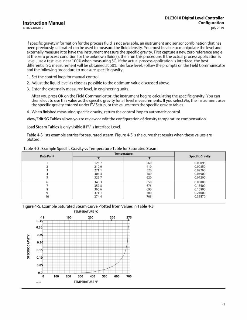
Instruction ManualD102748X012
DLC3010 Digital Level ControllerConfiguration
July 2019
47
If specific gravity information for the process fluid is not available, an instrument and sensor combination that hasbeen previously calibrated can be used to measure the fluid density. You must be able to manipulate the level andexternally measure it to have the instrument measure the specific gravity. First capture a new zero reference angleat the zero process condition for the unknown fluid(s), then run this procedure. If the actual process application isLevel, use a test level near 100% when measuring SG. If the actual process application is interface, the bestdifferential SG measurement will be obtained at 50% interface level. Follow the prompts on the Field Communicatorand the following procedure to measure specific gravity:
1. Set the control loop for manual control.
2. Adjust the liquid level as close as possible to the optimum value discussed above.
3. Enter the externally measured level, in engineering units.
After you press OK on the Field Communicator, the instrument begins calculating the specific gravity. You canthen elect to use this value as the specific gravity for all level measurements. If you select No, the instrument usesthe specific gravity entered under PV Setup, or the values from the specific gravity tables.
4. When finished measuring specific gravity, return the control loop to automatic control.
View/Edit SG Tables allows you to review or edit the configuration of density temperature compensation.
Load Steam Tables is only visible if PV is Interface Level.
Table 4‐3 lists example entries for saturated steam. Figure 4‐5 is the curve that results when these values areplotted.
Table 4‐3. Example Specific Gravity vs Temperature Table for Saturated Steam
Data PointTemperature
Specific Gravity�C �F
12345
126.7210.0271.1304.4326.7
260410520580620
0.000950.008500.027600.049000.07200
6789
10
343.3357.8365.6371.1374.4
650676690700706
0.098000.135000.168000.210000.31570
Figure 4‐5. Example Saturated Steam Curve Plotted from Values in Table 4‐3
0.0
0.05
0.10
0.15
0.20
0.25
0.30
0.35
0 100 200 300 400 500 600 700
SP
EC
IFIC
GR
AV
ITY
TEMPERATURE �F
-18 100 200 300 375
TEMPERATURE �C
E0370
Instruction ManualD102748X012
DLC3010 Digital Level ControllerConfigurationJuly 2019
48
Device IdentificationField Communicator Configure > Manual Setup > Device Identification (2-2-5)
Follow the prompts on the Field Communicator display to view or edit information in the following fields.
� Tag (also called HART tag) is a unique name (up to eight characters) that identifies the physical instrument.
� Instrument Serial Number— Use this field to enter or view the serial number on the instrument nameplate, up to 12characters.
� Sensor Serial Number— Use this field to enter or view the sensor serial number. The sensor serial number is found onthe sensor nameplate.
� Final Assembly Number— A number that can be used to identify the instrument and sensor combination.
� Date provides a place to save the date of the last revision of configuration or calibration information. It has noimpact on the operation of the controller or Field Communicator. The format, such as MM/DD/YYYY, will becontrolled by the settings of the host operating system.
� Description provides a longer user‐defined electronic label to assist with more specific controller identification thanis available with the HART tag. The descriptor may be up to 16 characters long and has no impact on the operationof the controller or HART‐based communicator.
� Message provides the most specific user‐defined means for identifying individual controllers in multi‐controllerenvironments. it allows for 32 characters of information and is stored with the other configuration data. Messagehas no impact on the operation of the controller or the Field Communicator.
CommunicationsField Communicator Configure > Manual Setup > Communications (2-2-6)
� Polling Address— If the digital level controller is used in a point‐to‐point configuration, the Polling Address is 0.When several devices are connected in the same loop, each device must be assigned a unique polling address. ThePolling Address may be set to a value between 0 and 15. A device with polling address greater than 0 will operate inMulti-Drop mode, with output current fixed. Any process information from a device in Multi-Drop mode must beobtained via HART communication.
� Burst Mode— Enabling burst mode provides continuous communication from the digital level controller.
Note
It may be difficult to make configuration adjustments to the DLC3010 while it is in burst mode, due to an increase incommunication errors. To reconfigure the device, it is advisable to first disable burst mode.
Depending upon the burst option selected, the digital level controller will burst the variables as shown in table 4‐4.
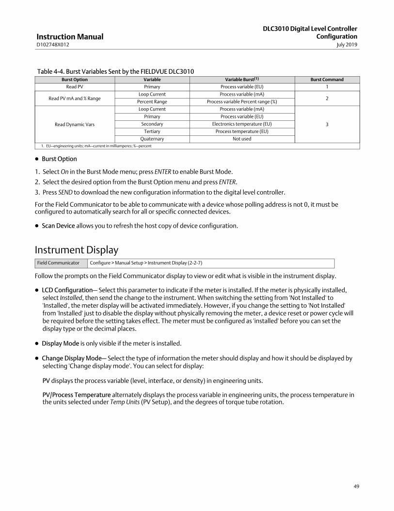
Instruction ManualD102748X012
DLC3010 Digital Level ControllerConfiguration
July 2019
49
Table 4‐4. Burst Variables Sent by the FIELDVUE DLC3010Burst Option Variable Variable Burst(1) Burst Command
Read PV Primary Process variable (EU) 1
Read PV mA and % RangeLoop Current Process variable (mA)
2Percent Range Process variable Percent range (%)
Read Dynamic Vars
Loop Current Process variable (mA)
3
Primary Process variable (EU)
Secondary Electronics temperature (EU)
Tertiary Process temperature (EU)
Quaternary Not used
1. EU—engineering units; mA—current in milliamperes; %—percent
� Burst Option
1. Select On in the Burst Mode menu; press ENTER to enable Burst Mode.
2. Select the desired option from the Burst Option menu and press ENTER.
3. Press SEND to download the new configuration information to the digital level controller.
For the Field Communicator to be able to communicate with a device whose polling address is not 0, it must beconfigured to automatically search for all or specific connected devices.
� Scan Device allows you to refresh the host copy of device configuration.
Instrument DisplayField Communicator Configure > Manual Setup > Instrument Display (2-2-7)
Follow the prompts on the Field Communicator display to view or edit what is visible in the instrument display.
� LCD Configuration— Select this parameter to indicate if the meter is installed. If the meter is physically installed,select Installed, then send the change to the instrument. When switching the setting from 'Not Installed' to'Installed', the meter display will be activated immediately. However, if you change the setting to 'Not Installed'from 'Installed' just to disable the display without physically removing the meter, a device reset or power cycle willbe required before the setting takes effect. The meter must be configured as 'installed' before you can set thedisplay type or the decimal places.
� Display Mode is only visible if the meter is installed.
� Change Display Mode— Select the type of information the meter should display and how it should be displayed byselecting 'Change display mode'. You can select for display:
PV displays the process variable (level, interface, or density) in engineering units.
PV/Process Temperature alternately displays the process variable in engineering units, the process temperature inthe units selected under Temp Units (PV Setup), and the degrees of torque tube rotation.

Instruction ManualD102748X012
DLC3010 Digital Level ControllerConfigurationJuly 2019
50
% Range displays the process variable as a percent of span (determined by the LRV and URV).
PV/% Range alternately displays the process variable in engineering units and the process variable in percent ofspan.
� Decimal Places—Select the number of decimal places to display, up to four. Setting the value to zero puts thedisplay in auto‐scale mode. It will then display as many decimals places as will fit.
If PV/Proc Temp or PV/% Range is selected, the display alternates every two seconds between the selected readings.The meter also simultaneously displays the analog output signal using a percent of scale bar graph around theperimeter of the display face as shown in figure 4‐6, no matter what display type is selected.
Figure 4‐6. LCD Meter Display
WHEN PRESENT, INDICATES WRITE PROTECTED
PROCESS VARIABLE VALUE
MODE
PROCESS VARIABLE UNITS
ANALOG OUTPUT DISPLAY
E0371
After you have selected the desired meter settings, press SEND on the Field Communicator to download the metersettings to the instrument.
Instruction ManualD102748X012
DLC3010 Digital Level ControllerConfiguration
July 2019
51
Alert Setup
Note
Take care not to configure the low alert threshold for a signal to a higher value than its high threshold, or both high and low alertsfor that signal could become active at the same time.
The following menus are available for configuring Alerts.
Primary VariableField Communicator Configure > Alert Setup > Primary Variable (2-3-1)
Follow the prompts on the Field Communicator display to view or edit the following primary variable alerts.
High Alerts
� HiHi Enable— On or Off. PV High High Alert Enable activates checking the primary variable against the PV High‐HighThreshold. The High High Alert is set if the primary variable rises above the PV High High Threshold Once the alert isset, the primary variable must fall below the PV High High Threshold by the PV Deadband before the alert is cleared.See figure 4‐10.
� PV HiHi Threshold— Primary Variable HiHi Threshold is the value of the process variable, in engineering units, which,when exceeded, sets the Primary Variable High‐High Alert.
� Manage HiHi Alert— Method to coordinate Hi Hi alert configuration with alarm jumper and other alerts.
� Hi Enable— On or Off. High Enable activates checking the primary variable against the PV High Threshold. The HighAlert is set if the primary variable rises above the PV High Threshold. Once the alert is set, the primary variable mustfall below the PV High Threshold by the PV Deadband before the alert is cleared. See figure 4‐10.
� PV Hi Threshold— Primary Variable Hi Threshold is the value of the process variable, in engineering units, which,when exceeded, sets the Primary Variable High Alert.
� Edit Hi Threshold— Method to change the PV Hi Threshold. The entered value is checked against the otherthresholds to help avoid overlap.
� PV Value is the current value of PV for reference.
� Upper Range Value is the value of URV for reference.
� Lower Range Value is the value of LRV for reference.

Instruction ManualD102748X012
DLC3010 Digital Level ControllerConfigurationJuly 2019
52
Note
If the Hi Hi Alert is enabled and tripped, the digital level controller output will go to 3.75 mA or 22.5 mA, depending on theposition of the alarm jumper. Consider the effect of an alarm annunciation on the process, then set alarm jumper positionaccordingly.
When Output Action is 'Direct':
� A Hi alarm setting will result in an alarm-state output consistent with a very high process.
� A Lo alarm setting will result in an alarm-state output consistent with a very low process.
When Output Action is 'Reverse', these relationships are swapped.
See figure 4‐7 and 4‐8 and examples below to clarify the shape of the Analog Output transfer function under various PV alertconfigurations. Note that the Low Alarm Current capability is not NAMUR NE 43 compliant.
Examples:
If the device is driving a valve in a series analog loop, you would normally want to use an alarm current value that will move thevalve in the direction that clears the alarm situation. A Hi-Hi alarm condition should generate a signal that will stop a vessel fromoverflowing.
If the control valve is in the outflow or dump line you will want to open the valve. If the dump valve opens for an increasing currentsignal, you would select Plot A in figure 4‐8 (HiHi Alert enabled, High Current alarm jumper position, Direct action).
To keep a vessel from overflowing when the control valve is in the inflow pipe, you will want to close the valve. If the fill valve opensfor an increasing current signal, you would select Plot B in figure 4‐8 (HiHi Alert enabled, Low Current alarm jumper position,Reverse action).
If the device is driving the input to a control system that uses NAMUR NE 43 levels to alarm, instead of directly driving a valve, youmight choose the High Current alarm jumper position even for Reverse action (Plot D in figure 4‐8), as the DLC3010 low currentalarm isn’t low enough to guarantee a NAMUR NE 43 trip (Plots B and C in figure 4‐8).
If the control system receiving the DLC3010 4-20 mA signal has its own PV alert thresholds and alarm strategy, you wouldprobably disable the DLC3010's internal HiHi PV alert and use only the control system's PV alerts. (The DLC3010 hardware alertswould still drive the analog output signal to the Alarm Jumper setting in that case.)
In a Multi-Drop network (device has a non-zero Polling Address), alarm annunciation is disabled and the device is not directlydriving any effector, so jumper setting is not a concern.
Figure 4‐7. PV Alerts Disabled
24
22
20
18
16
14
12
10
8
6
4
2
24
22
20
18
16
14
12
10
8
6
4
2
-2 0� � 2 4 6 8 10 12 -2 0� � 2 4 6 8 10 12
PV (m) PV (m)
PV ALERTS: DISABLEDOUTPUT ACTION: DIRECTRANGE: 0 TO 10 m
PV ALERTS: DISABLEDOUTPUT ACTION: REVERSERANGE: 10 TO 0 m
DEVICE OUTPUT (mA) DEVICE OUTPUT (mA)

Instruction ManualD102748X012
DLC3010 Digital Level ControllerConfiguration
July 2019
53
Figure 4‐8. PV HiHi Alerts
24
22
20
18
16
14
12
10
8
6
4
2-2 0� 2 4 6 8 10�� 12
24
22
20
18
16
14
12
10
8
6
4
2
PV (m)
DEVICE OUTPUT (mA)
PV (m)
DEVICE OUTPUT (mA)
PV (m) PV (m)
DEVICE OUTPUT (mA)DEVICE OUTPUT (mA)
PV HIHI ALERT ENABLEDHIHI THRESHOLD: 9 mALARM SETTING: HIGHOUTPUT ACTION: DIRECTRANGE: 0 TO 10 m
PV HIHI ALERT ENABLEDHIHI THRESHOLD: 9 mALARM SETTING: LOWOUTPUT ACTION: REVERSERANGE: 10 TO 0 m
PV HIHI ALERT ENABLEDHIHI THRESHOLD: 9 mALARM SETTING: LOWOUTPUT ACTION: DIRECTRANGE: 0 TO 10 m
PV HIHI ALERT ENABLEDHIHI THRESHOLD: 9 mALARM SETTING: HIGHOUTPUT ACTION: REVERSERANGE: 10 TO 0 m
NAMUR NE 43 HIGH ALARM LEVEL
NAMUR NE 43 LOW ALARM LEVEL
24
22
20
18
16
14
12
10
8
6
4
2
-2 0� 2 4 6 8 10�� 12
-2 0� 2 4 6 8 10�� 12
24
22
20
18
16
14
12
10
8
6
4
2-2 0� 2 4 6 8 10�� 12
NAMUR NE 43 LOW ALARM LEVEL
NAMUR NE 43 HIGH ALARM LEVEL
PLOT A PLOT B
PLOT C PLOT D
1
1
1��NOTE THAT THE LOW ALARM CURRENT CAPABILITY IS NOT NAMUR NE 43 COMPLIANT.
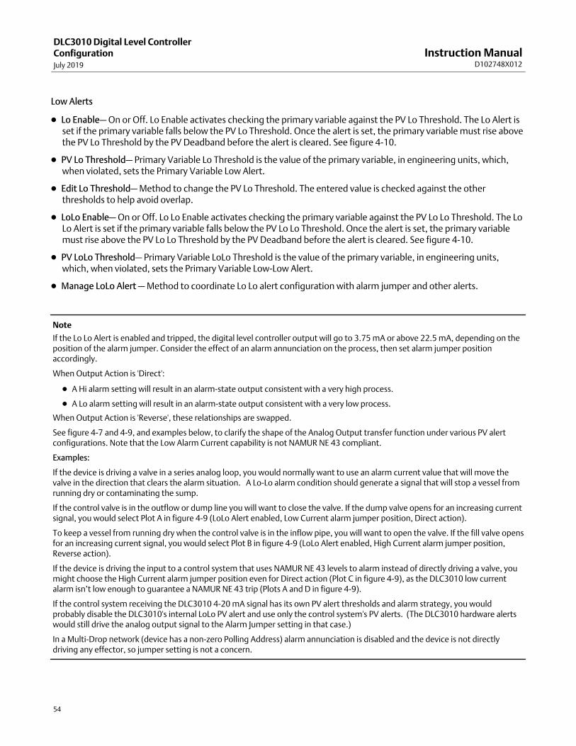
Instruction ManualD102748X012
DLC3010 Digital Level ControllerConfigurationJuly 2019
54
Low Alerts
� Lo Enable— On or Off. Lo Enable activates checking the primary variable against the PV Lo Threshold. The Lo Alert isset if the primary variable falls below the PV Lo Threshold. Once the alert is set, the primary variable must rise abovethe PV Lo Threshold by the PV Deadband before the alert is cleared. See figure 4‐10.
� PV Lo Threshold— Primary Variable Lo Threshold is the value of the primary variable, in engineering units, which,when violated, sets the Primary Variable Low Alert.
� Edit Lo Threshold— Method to change the PV Lo Threshold. The entered value is checked against the otherthresholds to help avoid overlap.
� LoLo Enable— On or Off. Lo Lo Enable activates checking the primary variable against the PV Lo Lo Threshold. The LoLo Alert is set if the primary variable falls below the PV Lo Lo Threshold. Once the alert is set, the primary variablemust rise above the PV Lo Lo Threshold by the PV Deadband before the alert is cleared. See figure 4‐10.
� PV LoLo Threshold— Primary Variable LoLo Threshold is the value of the primary variable, in engineering units,which, when violated, sets the Primary Variable LowLow Alert.
� Manage LoLo Alert — Method to coordinate Lo Lo alert configuration with alarm jumper and other alerts.
Note
If the Lo Lo Alert is enabled and tripped, the digital level controller output will go to 3.75 mA or above 22.5 mA, depending on theposition of the alarm jumper. Consider the effect of an alarm annunciation on the process, then set alarm jumper positionaccordingly.
When Output Action is 'Direct':
� A Hi alarm setting will result in an alarm-state output consistent with a very high process.
� A Lo alarm setting will result in an alarm-state output consistent with a very low process.
When Output Action is 'Reverse', these relationships are swapped.
See figure 4‐7 and 4‐9, and examples below, to clarify the shape of the Analog Output transfer function under various PV alertconfigurations. Note that the Low Alarm Current capability is not NAMUR NE 43 compliant.
Examples:
If the device is driving a valve in a series analog loop, you would normally want to use an alarm current value that will move thevalve in the direction that clears the alarm situation. A Lo-Lo alarm condition should generate a signal that will stop a vessel fromrunning dry or contaminating the sump.
If the control valve is in the outflow or dump line you will want to close the valve. If the dump valve opens for an increasing currentsignal, you would select Plot A in figure 4‐9 (LoLo Alert enabled, Low Current alarm jumper position, Direct action).
To keep a vessel from running dry when the control valve is in the inflow pipe, you will want to open the valve. If the fill valve opensfor an increasing current signal, you would select Plot B in figure 4‐9 (LoLo Alert enabled, High Current alarm jumper position,Reverse action).
If the device is driving the input to a control system that uses NAMUR NE 43 levels to alarm instead of directly driving a valve, youmight choose the High Current alarm jumper position even for Direct action (Plot C in figure 4‐9), as the DLC3010 low currentalarm isn’t low enough to guarantee a NAMUR NE 43 trip (Plots A and D in figure 4‐9).
If the control system receiving the DLC3010 4-20 mA signal has its own PV alert thresholds and alarm strategy, you wouldprobably disable the DLC3010's internal LoLo PV alert and use only the control system's PV alerts. (The DLC3010 hardware alertswould still drive the analog output signal to the Alarm Jumper setting in that case.)
In a Multi-Drop network (device has a non-zero Polling Address) alarm annunciation is disabled and the device is not directlydriving any effector, so jumper setting is not a concern.

Instruction ManualD102748X012
DLC3010 Digital Level ControllerConfiguration
July 2019
55
24
22
20
18
16
14
12
10
8
6
4
2
PV (m)
DEVICE OUTPUT (mA)
-2 0� 2 4 6 8 10�� 12
PV LOLO ALERT ENABLEDLOLO THRESHOLD: 2 mALARM SETTING: HIGHOUTPUT ACTION: REVERSERANGE: 10 TO 0 m
Figure 4‐9. PV LoLo Alerts
24
22
20
18
16
14
12
10
8
6
4
2
-2 0� 2 4 6 8 10�� 12
PV (m)
DEVICE OUTPUT (mA)
PV (m) PV (m)
DEVICE OUTPUT (mA)DEVICE OUTPUT (mA)
PV LOLO ALERT ENABLEDLOLO THRESHOLD: 2 mALARM SETTING: LOWOUTPUT ACTION: DIRECTRANGE: 0 TO 10 m
PV LOLO ALERT ENABLEDLOLO THRESHOLD: 2 mALARM SETTING: LOWOUTPUT ACTION: REVERSERANGE: 10 TO 0 m
NAMUR NE 43 LOW ALARM LEVEL
24
22
20
18
16
14
12
10
8
6
4
2
-2 0� 2 4 6 8 10�� 12
24
22
20
18
16
14
12
10
8
6
4
2
-2 0� 2 4 6 8 10�� 12
NAMUR NE 43 HIGH ALARM LEVEL
NAMUR NE 43 HIGH ALARM LEVEL
PV LOLO ALERT ENABLEDLOLO THRESHOLD: 2 mALARM SETTING: HIGHOUTPUT ACTION: DIRECTRANGE: 0 TO 10 m NAMUR NE 43 LOW ALARM LEVEL
PLOT A PLOT B
PLOT C PLOT D
1��NOTE THAT THE LOW ALARM CURRENT CAPABILITY IS NOT NAMUR NE 43 COMPLIANT.
1
1
� PV Value is the current process variable (level, interface, or density) in engineering units.
� Upper Range Value is the highest value of the primary variable that the digital level controller is currently configuredto measure in the 4 to 20 mA loop.
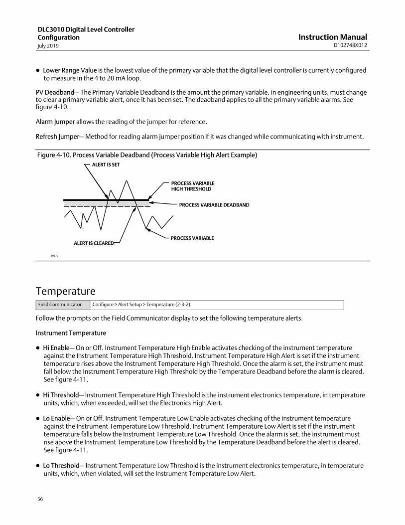
Instruction ManualD102748X012
DLC3010 Digital Level ControllerConfigurationJuly 2019
56
� Lower Range Value is the lowest value of the primary variable that the digital level controller is currently configuredto measure in the 4 to 20 mA loop.
PV Deadband— The Primary Variable Deadband is the amount the primary variable, in engineering units, must changeto clear a primary variable alert, once it has been set. The deadband applies to all the primary variable alarms. Seefigure 4‐10.
Alarm Jumper allows the reading of the jumper for reference.
Refresh Jumper— Method for reading alarm jumper position if it was changed while communicating with instrument.
Figure 4‐10. Process Variable Deadband (Process Variable High Alert Example)
ALERT IS CLEARED
ALERT IS SET
PROCESS VARIABLEHIGH THRESHOLD
PROCESS VARIABLE DEADBAND
E0372
PROCESS VARIABLE
TemperatureField Communicator Configure > Alert Setup > Temperature (2-3-2)
Follow the prompts on the Field Communicator display to set the following temperature alerts.
Instrument Temperature
� Hi Enable— On or Off. Instrument Temperature High Enable activates checking of the instrument temperatureagainst the Instrument Temperature High Threshold. Instrument Temperature High Alert is set if the instrumenttemperature rises above the Instrument Temperature High Threshold. Once the alarm is set, the instrument mustfall below the Instrument Temperature High Threshold by the Temperature Deadband before the alarm is cleared.See figure 4‐11.
� Hi Threshold— Instrument Temperature High Threshold is the instrument electronics temperature, in temperatureunits, which, when exceeded, will set the Electronics High Alert.
� Lo Enable— On or Off. Instrument Temperature Low Enable activates checking of the instrument temperatureagainst the Instrument Temperature Low Threshold. Instrument Temperature Low Alert is set if the instrumenttemperature falls below the Instrument Temperature Low Threshold. Once the alarm is set, the instrument mustrise above the Instrument Temperature Low Threshold by the Temperature Deadband before the alert is cleared.See figure 4‐11.
� Lo Threshold— Instrument Temperature Low Threshold is the instrument electronics temperature, in temperatureunits, which, when violated, will set the Instrument Temperature Low Alert.

Instruction ManualD102748X012
DLC3010 Digital Level ControllerConfiguration
July 2019
57
� Instrument Temperature— Current Instrument Temperature.
Process Temperature
� Hi Enable— On or Off. Process Temperature High Enable activates checking of the process variable temperatureagainst the Process Temperature High Threshold. The Process Temperature High Alert is set if the processtemperature rises above the Process Temperature High Threshold. Once the alert is set, the process variabletemperature must fall below the Process Temperature High Threshold by the Temperature Deadband before thealert is cleared. See figure 4‐11.
� Hi Threshold— Process Temperature High Threshold is the process variable temperature, in temperature units,which, when exceeded, will set the Process Temperature High Alert.
� Lo Enable— On or Off. Process Temperature Low Enable activates checking of the process temperature against theProcess Temperature Low Threshold. The Process Temperature Low Alert is set if the process temperature fallsbelow the Process Temperature Low Threshold. Once the alert is set, the process temperature must rise above theProcess Temperature Low Threshold by the Temperature Deadband before the Alert is cleared. See figure 4‐11.
� Lo Threshold— Process Temperature Low Threshold is the process variable temperature, in temperature units,which, when violated, will set the Temperature Low Alert.
� Process Temperature displays the process temperature stored in (or measured by) the instrument for reference.
� Process Temperature Source is the source of process temperature parameter for reference.
� Usage— If Process Temperature Source is 'Manual Entry', the only use for the Process Temperature alerts would beto identify an entry outside of the compensation table range.
Temperature Deadband is the amount the temperature, in temperature units, must change to clear a temperaturealert, once it has been set. The deadband applies to all the temperature alerts. See figure 4‐11.
Figure 4‐11. Temperature Deadband (Temperature High Alert Example)
ALERT IS CLEARED
ALERT IS SET
PROCESS TEMPERATUREHIGH THRESHOLD
TEMPERATURE DEADBAND
E0373
TEMPERATURE

Instruction ManualD102748X012
DLC3010 Digital Level ControllerConfigurationJuly 2019
58
Calibration
Introduction: Calibration of Smart InstrumentsAnalog instruments generally have only one interface that can be calibrated by the user. A zero and span outputcalibration is normally performed at the corresponding two input conditions. Zero/Span calibration is very simple touse, but provides little versatility. If the 0% and 100% input conditions are not available to the user, a calibration cansometimes be accomplished, but the gain and offset adjustments will likely interact, requiring considerable iterationto achieve accuracy. In contrast, intelligent instruments have many interfaces that can be calibrated or scaled by theuser, with consequent increased versatility.
Refer to table 4‐5 for a list of relationships in the DLC3010 that can be calibrated or configured by the user. Note thatnot all relationships are listed here.
Table 4‐5. Relationships in the FIELVUE DLC3010 that can be User Calibrated or Configured
Torque Tube Rate The scale factor between the internal digital representation of the measured pilot shaft rotation and the physical torqueinput to the sensor.
Zero Reference Angle The angle of pilot shaft rotation associated with the zero buoyancy condition in Interface or Density mode, or the zerodifferential buoyancy condition in Level mode. (The zero reference for the input of the PV calculation).
Driver Rod LengthThe scale factor (moment arm) between a force input to the sensor driver rod and the torque developed as input to thetorque tube.
Displacer VolumeThe scale factor relating the density of the process fluid to the maximum force that can be produced as an input to thedriver rod of the sensor.
SGThe density of the process fluid normalized to the density of water at reference conditions. The scale factor thattransforms displacer volume and measured buoyancy into a level signal normalized to displacer length.
Displacer Length The scale factor to convert normalized level to level on the displacer in engineering units.
Level Offset The zero reference for the output of the PV calculation, referred to the location of the bottom of the displacer.
URV (Upper Range Value) The value of computed process variable at which a 20 mA output (100% Range) is desired.
LRV (Lower Range Value) The value of computed process variable at which a 4 mA output (0% Range) is desired.
D/A Trim The gain and offset of the D/A converter which executes the digital commands to generate output
Instrument Temperature OffsetBias to improve the accuracy of the ambient temperature measurement used to provide temperature compensation forthe mechanical‐to‐electronic transducer.
Proc Temp OffsetBias to improve the accuracy of the (RTD) temperature measurement used to provide compensation forprocess‐temperature‐related density changes.
These parameters are factory‐set to the most common values for the 249 sensors. Therefore, for the bulk of units soldin simple level applications, it is possible to accept the defaults and run a Min/Max Calibration. If any of the advancedfeatures of the instrument are to be used, accurate sensor and test fluid information should generally be enteredbefore beginning the calibration.
Primary
Guided Calibration
Field Communicator Configure > Calibration > Primary > Guided Calibration (2-4-1-1)
Guided Calibration recommends an appropriate calibration procedures for use in the field or on the bench based onyour input. Answer questions about your process scenario to reach the calibration recommendation. When feasible,the appropriate calibration method will be invoked from within the procedure.
Instruction ManualD102748X012
DLC3010 Digital Level ControllerConfiguration
July 2019
59
Full Calibration
Field Communicator Configure > Calibration > Primary > Full Calibration (2-4-1-2)
Full Calibration operations compute the sensor gain and zero reference from two independent observations of processdata points. They are appropriate for cases where the two input conditions can be established relatively quickly in onesession.
Min/Max Calibration
The following procedure can be useful when process values can't be precisely observed, but the displacer cansequentially be submerged in fluids of known minimum and maximum density. (E.g., no sight glass is available, but thecage can be isolated and drained or flooded.)
Torque rate and input zero are computed from observed minimum and maximum process conditions, density data,displacer volume, and driver rod length.
Follow the prompts on the Field Communicator to calibrate the instrument and sensor.
1. Set the control loop for manual control.
2. Enter the specific gravity for the liquid in the system.
3. Adjust the liquid level until the displacer is dry (or completely submerged in upper liquid). Allow the output tosettle, then acknowledge establishment of the minimum buoyancy condition to the system.
4. Adjust the liquid level until the displacer is completely submerged in the lower liquid. Allow the output to settle,then acknowledge establishment of the maximum buoyancy condition of the system.
The sensor is calibrated. Verify that the upper and lower range values are correct and return the loop to automaticcontrol.
Two Point Calibration
This procedure uses independent observations of two valid process conditions, together with the hardwaredimensional data and SG information, to compute the effective torque rate and zero reference angle for the sensor.The two data points can be separated by any span between a minimum of 5% to 100%, as long as they remain on thedisplacer. Within this range, the calibration accuracy will generally increase as the data‐point separation gets larger.Accuracy is also improved by running the procedure at process temperature, as the temperature effect on torque ratewill be captured. (It is possible to use theoretical data to pre‐compensate the measured torque rate for a targetprocess condition when the calibration must be run at ambient conditions.)
An external method of measuring the process condition is required.
Follow the prompts on the Field Communicator to calibrate the sensor.
1. Put the control loop in manual control.
2. Adjust the process condition to a value near the top or bottom of the valid range.
3. Enter this externally measured process condition in the current PV units.
4. Adjust the process condition to a value near the bottom or top of the valid range, but at a position that is toward theopposite end of the range relative to the condition used in step 2.
5. Enter this second externally measured process condition in the current PV units.
The sensor is now calibrated. Be sure to verify that the upper and lower range values are correct before returning theloop to automatic control.
Weight Calibration
This procedure may be used on the bench or with a calibration jig that is capable of applying a mechanical force to thedriver rod to simulate displacer buoyancy changes. It allows the instrument and sensor to be calibrated using

Instruction ManualD102748X012
DLC3010 Digital Level ControllerConfigurationJuly 2019
60
equivalent weights or force inputs instead of using the actual displacer buoyancy changes. If the displacer informationhas been entered prior to beginning the procedure, the instrument will be able to compute reasonable weight valuesuggestions for the calibration. However, the only preliminary data essential for the correct calibration of the torquerate is the length of the driver rod being used for the calibration.
Weight equivalent to the net displacer weight at two valid process conditions must be available. The sensor must havebeen sized properly for the expected service, so that the chosen process conditions are in the free‐motion linear rangeof the sensor. The instrument should normally be physically coupled to the pilot shaft at what is going to be the zerobuoyancy weight or the zero differential‐buoyancy weight, depending on the calibration approach. (However, if theexpected operational travel of the pilot is greater than 5 degrees, it is advisable to couple the transmitter to the pilotshaft at the condition representing mid‐travel instead. This will prevent hitting a stop in the transmitter before limitingin the sensor.) A small zero trim correction may be necessary at start-up, since the weight input may not perfectlysimulate the actual process fluid(s).
Follow the prompts on the Field Communicator to calibrate the sensor.
1. Place a weight on the displacer rod that is approximately equal to that indicated on the prompt. The suggestedweight is equivalent to the effective displacer weight when the liquid is at its lowest level or the displacer issuspended in the liquid with the lower specific gravity. You may use a larger weight for greater separation betweendata points, so long as you don't hit the lower travel limit.
2. Enter the actual value of the weight suspended on the displacer rod. Check that a travel limit has not been reached,and allow the system to stabilize before continuing.
3. Place a weight on the displacer rod that is approximately equal to that indicated on the next prompt. The suggestedweight is equivalent to the effective displacer weight when the liquid is at its highest level or the displacer issuspended in the liquid with the higher specific gravity. You may use a smaller weight for greater separationbetween data points, so long as you don't hit the upper travel limit.
4. After allowing the system to stabilize, enter the actual value of the weight suspended on the displacer rod.
The sensor is calibrated, but a small zero trim may be required when the actual process fluid(s) are introduced. Checkthe range values before putting the loop in service.
Theoretical Calibration
In cases where it is not possible to manipulate the input at all, the user may set up a nominal calibration usinginformation available about the hardware and the process. The theoretical torque rate for the installed torque tubemay be looked up and compensated for process temperatures. This value is then manually entered in the instrumentconfiguration. (The Change Torque Rate procedure under the Manual Setup > Sensor > Torque Tube menu can be usedto look up and select theoretical values for common torque tubes if you select the Need Assistance option instead ofthe Edit value directly approach.) The displacer information and fluid SGs are entered. The desired range values areentered manually. Finally,Trim Zero computes PV to the current value of the process. It should be possible to controlthe loop with this rough calibration.
Note
The theoretical torque rate for the installed torque tube is available in the Simulation of Process Conditions for Calibration of FisherLevel Controllers and Transmitters instruction manual supplement (D103066X012). Contact your Emerson sales office forinformation on obtaining this manual supplement.
Observations of the sight glass or other independent measurements may be logged against DLC3010 outputs overtime. The ratio of the independent‐observable process changes to the DLC3010 output changes may then be used as ascale factor to modify the theoretical torque rate stored in the instrument. After each gain adjustment, a new zerotrim will be required. When a plant‐maintenance shutdown occurs, the instrument may be isolated and calibrated inthe normal manner.

Instruction ManualD102748X012
DLC3010 Digital Level ControllerConfiguration
July 2019
61
Partial CalibrationField Communicator Configure > Calibration > Primary > Partial Calibration (2-4-1-3)
Partial Calibration operations are useful when it would take too long to establish a second data point in a singlesession. There are of two types of partial calibrations: capture and trim. The 'capture zero' operation sets the input zeroreference angle to the value currently being measured. It is therefore valid only at the defined zero process condition.Trim operations recompute either gain or zero reference angle with one observation of process data. The calibrationparameter that is NOT being trimmed is assumed to be correct.
Capture Zero
Capture Zero captures the current value of the torque tube angle as the input zero. The displacer must be loading thetorque tube, and not resting on a travel stop. The torque tube must be coupled to the DLC3010 and the couplingaccess door must be closed. In Level mode, the captured angle represents zero differential buoyancy on displacer, andmust be obtained at the actual process zero condition. In Interface and Density mode, the captured angle representszero absolute buoyancy on displacer, and must be obtained at actual dry condition.
If the displacer is overweight and it is necessary to use the partial calibration methods, select Level mode and enter thedifferential density before using ‘Capture Zero’ and ‘Trim Gain’. After the gain is correct, switch back to Density orInterface mode, (reenter individual densities if Interface), then perform a ‘Trim Zero’ procedure to backcompute therequired zero buoyancy angle.
The Capture zero procedure prompts you to verify the instrument is coupled to torque tube, coupling access door isclosed, and the displacer is completely dry (if the PV is set to Interface Level), or the process input is at the zero levelcondition (if the PV is set to Liquid Level).
Note
If the handle on the coupling access door is in the position towards the front of the transmitter, the coupling access hole is openand the lever is “locked” (pinned in the neutral travel position). In this condition, the true “at‐rest” position of the linkage may notbe captured correctly. Moving the handle to the rear of the transmitter closes the coupling‐access hole and unlocks the lever.
The Zero Reference Angle functions as the pre‐calculation zero for the process measurement algorithm. Thisprocedure can be run either before or after other calibration procedures. However, the procedure returns a valid resultat only one input condition - zero buoyancy for Interface and zero differential buoyancy for Level mode.
Before calibration, use the Configure > Manual Setup >Sensor menu to verify that all sensor and compensation datamatch the calibration conditions.
Trim Gain
Trim Gain operations recompute gain with one observation of process data.
Trim Gain trims the torque rate value to align the digital Primary Variable with the user’s observation. This calibrationassumes that sensor zero is already accurate and only a gain error exists. Actual process condition must be nonzeroand able to be measured independently. Configuration data must contain density of calibration fluid(s), displacervolume, and driver rod length.
Before calibration, use the Configure > Manual Setup >Sensor menu to verify that all sensor and compensation datamatch the calibration conditions.
Trim Zero
Trim Zero computes the value of the input angle required to align the digital Primary Variable with the user’sobservation of the process, and corrects the stored input zero reference, assuming that the calibration gain is

Instruction ManualD102748X012
DLC3010 Digital Level ControllerConfigurationJuly 2019
62
accurate. Use this procedure when the process cannot be moved to zero for capture, but gain is known to be correct(only a bias error exists).
Before calibration, use the Configure > Manual Setup >Sensor menu to verify that all sensor and compensation datamatch the calibration conditions.
Follow the prompts on the Field Communicator.
1. Adjust the process condition or simulation to any valid and observable value.
2. Enter the external observation of the measurement in the current PV units.
Secondary
Temperature Calibration
Field Communicator Configure > Calibration > Secondary > Temperature Calibration (2-4-2-1)
This procedure allows you to display the temperature as measured by the instrument. You can then trim thetemperature reading so that it matches the actual temperature more closely in the region of interest. (This is an offsetadjustment only. There is no ability to change the gain.)
This calibration is initially performed at the factory. Performing it in the field requires an accurate independentmeasurement of the instrument housing temperature or process temperature, (as appropriate). The instrumentshould be at a steady‐state condition with respect to that temperature when performing the procedure.
Note
The effectiveness of the instrument electronic temperature compensation depends upon the accuracy of the electronicstemperature offset stored in the NVM (non‐volatile memory). If the electronics temperature is incorrect, the temperature curveapplied to the magnets and Hall sensor will be misaligned, resulting in over‐ or under‐compensation.
� Instrument Temperature is the value currently reported by instrument.
� Instrument Temperature Offset is the current trim value in use by instrument.
� Trim Instrument Temperature— Follow the prompts on the Field Communicator to trim the instrumenttemperature.
� Process Temperature is the value currently reported by instrument.
� Process Temperature Offset is the current trim value in use by instrument.
� Trim Process Temperature is available if the Process Temperature Source is not Manual. Follow the prompts on theField Communicator to trim the process temperature.
Note
If a process temperature sensor (RTD) is not installed, it is possible to manually set the Digital Process Temperature variable to thetarget process temperature. Go to Configure > Manual Setup > Process Conditions > Temperature Setting.

Instruction ManualD102748X012
DLC3010 Digital Level ControllerConfiguration
July 2019
63
Analog Output Calibration
Scaled D/A Trim
Field Communicator Configure > Calibration > Secondary > Analog Output Calibration > Scaled D/A Trim (2-4-2-2)
This procedure allows trimming the gain and offset of the Digital‐to‐Analog (D/A) converter to adjust the accuracy atwhich the output follows 4 to 20 mA current commands from the firmware. This relationship is initially set in thefactory, and should not require frequent user adjustment. Reasons for using this procedure include:
� Correction for component aging after the instrument has been in service for an extended period.
� Adjusting D/A calibration to be optimum at the normal operating temperature, when that temperature isconsiderably removed from room temperature conditions.
The procedure is iterative, and will eventually reach a resolution limit where attempts to improve the result will cycleat a few decimal places to either side of the target.
Follow the prompts on the Field Communicator to trim the D/A output.
1. Scale the output from 4 to 20 mA? If your reference meter is graduated in “mA”, select Proceed and go to step 5. Ifthe reference reading is presented in some other unit system, such as “%” or “mm”, select Change and continuewith step 2.
2. Enter the scale low output value.
3. Enter the scale high output value.
4. If the high and low output values are correct, select Proceed and continue to step 5. If they are not correct, selectChange and return to step 2.
5. Connect a reference meter across the test connections in the terminal box. See the Test Connections procedure inthe Installation section. You can also connect a reference meter in the loop as shown in figure 2‐9.
6. The Field Communicator commands the instrument to set its output to 4 mA or the low output value.
7. Enter the reading from the reference meter.
8. If the reference meter reading equals 4 mA or the low output value, select Yes and continue to step 9. If not, selectNo and return to step 7.
9. The Field Communicator commands the instrument to set its output to 20 mA or the high output value.
10. Enter the reading from the reference meter.
11. If the reference meter reading equals 20 mA or the high output value, select Yes and continue to step 12. If not,select No and return to step 10.
12. The Field Communicator commands the instrument to set its output back to the original value.
Note
If communications with the device are lost before exit of the procedure, the device may be stuck in fixed output current mode. Besure to check for the 'Analog Output Fixed' alert after communications are re-established, or disturb the input linkage and confirmoutput current change before returning the loop to Auto.
Calibration Examples
Calibration—with Standard Displacer and Torque TubeRun the initial calibration near ambient temperature at design span to take full advantage of the available resolution.This is accomplished by using a test fluid with a specific gravity (SG) close to 1. The value of SG in the instrument
Instruction ManualD102748X012
DLC3010 Digital Level ControllerConfigurationJuly 2019
64
memory during the calibration process should match the SG of the test fluid being used in the calibration. After theinitial calibration, the instrument may be set up for a target fluid with a given specific gravity, or an interfaceapplication, by simple configuration data changes.
1. Run through Guided Setup and verify that all sensor data is correct.Procedure:Change the PV mode to Level If your input observations are going to be made with respect to location of the bottom of the displacer at thelowest process condition, set the Level Offset value to 0.00, andSet the Specific Gravity value to the SG of the test fluid being used.
Establish the test fluid level at the desired process zero point. Make sure that the DLC3010 lever assembly has beenproperly coupled to the torque tube (see coupling procedure on page 39). To unlock the lever assembly and allow it tofreely follow the input, close the coupling access door on the instrument. It is often possible to watch the instrumentdisplay and/or the analog output to detect when the fluid hits the displacer, because the output will not start movingupward until that point is reached.
Select the Min/Max calibration from the Full Calibration menu, and confirm that you are at the 'Min' condition at theprompt. After the 'Min' point has been accepted, you will be prompted to establish the 'Max' condition. (The 'displacercompletely covered' condition should be slightly higher than the 100% level mark to work correctly. for example, 15inches above the zero mark would generally be enough for a 14 inch displacer on a 249B, because the amount ofdisplacer rise expected for that configuration is about 0.6 inch.)
Accept this as the 'Max' condition. Adjust the test fluid level and check the instrument display and current outputagainst external level at several points distributed across the span to verify the level calibration.
a. To correct bias errors, 'Trim Zero' at a precisely known process condition.
b. To correct gain errors, 'Trim Gain' at a preciselyknown high level condition.
Note
If you are able to precisely observe individual input states, the Two-Point calibration may be used instead of Min/Max.
If for some reason you are unable to carry out Min/Max or Two Point Calibration, set the lowest process condition and CaptureZero. Run Trim Gain at a process level of minimum 5% above the Lower Range Value.
If the measured output doesn't come off the low saturation value until the level is considerably above the bottom ofthe displacer, it is possible that the displacer is overweight. An overweight displacer will rest on the lower travel stopuntil sufficient buoyancy has developed to allow the linkage to move. In that case, use the calibration procedure foroverweight displacers found below.
After the initial calibration:
For a liquid level application— Go to the Sensor Compensation menu and use the 'Enter constant SG' item to configurethe instrument for the target process fluid density.
For an interface level application— Change the PV mode to Interface, verify or adjust the range values presented by theChange PV mode procedure, and then use 'Enter constant SG' to configure the instrument for the SGs of each of thetarget process fluids.
For a liquid density application— Change the PV mode to Density, and establish the desired range values in the 'ChangePV mode' procedure.
Instruction ManualD102748X012
DLC3010 Digital Level ControllerConfiguration
July 2019
65
If the target application temperature is considerably elevated or depressed from ambient, refer to pages 45 and 70 forinformation on temperature compensation.
Note
Information on computing precise simulation of this effect is available in the Simulation of Process Conditions for Calibration ofFisher Level Controllers and Transmitters instruction manual supplement (D103066X012), available from your Emerson salesoffice or at Fisher.com.
Calibration with an Overweight Displacer
When the sensor hardware is sized for greater mechanical gain (as it is in some interface or density measurementapplications), the dry displacer weight is often greater than the maximum permissible load on the torque tube. In thissituation it is impossible to 'capture' the zero buoyancy rotation of the torque tube, because the linkage is lying on atravel stop at that condition.
The 'Capture Zero' routine in the Partial Calibration menu group will therefore not function correctly in the target PVmodes of Interface or Density when the displacer is overweight.
The Full Calibration routines: Min/Max, TwoPoint, and Weight, will all work correctly at the actual process conditionswhen in interface or density mode, because they backcompute the theoretical zerobuoyancy angle instead ofcapturing it.
If it is necessary to use the Partial Calibration methods when the displacer is overweight, the following transformationmay be used:
An interface or density application can be mathematically represented as a level application with a single fluid whosedensity is equal to the difference between the actual SGs of the fluid covering the displacer at the two processextremes.
The calibration process flows as follows:
� Change the PV mode to Level.
� Set the Level Offset to zero.
� Set the Range Values to: LRV = 0.0, URV = displacer length.
� Set Specific Gravity to the difference between the SGs of the two fluids (for example, if SG_upper = 0.87 andSG_lower = 1.0, enter a specific gravity value of 0.13).
� Capture Zero at the lowest process condition (that is, with the displacer completely submerged in the fluid ofthe lowest density NOT dry).
� Set up a second process condition more than 5% of span above the minimum process condition, and use the TrimGain procedure at that condition. The gain will now be initialized correctly. (The instrument would work fine inthis configuration for an interface application. However, if you have a density application, it won't be possible toreport the PV correctly in engineering units if the instrument calibration is concluded at this point.)
Instruction ManualD102748X012
DLC3010 Digital Level ControllerConfigurationJuly 2019
66
Since you now have a valid gain:
� Change the PV mode to Interface or Density,
� reconfigure the fluid SGs or range values to the actual fluid values or extremes, and
� use the Trim Zero procedure in the Partial Calibration menu to backcompute the theoretical zerobuoyancyangle.
The last step above will align the value of the PV in engineering units to the independent observation.
Note
Information on simulating process conditions is available in the Simulation of Process Conditions for Calibration of Fisher LevelControllers and Transmitters instruction manual supplement (D103066X012), available from your Emerson sales office or atFisher.com.
Following are some guidelines on the use of the various sensor calibration methods when the application uses anoverweight displacer:
Weight‐based: Use two accurately known weights between minimum and maximum buoyancy conditions. The fulldisplacer weight is invalid because it will put the linkage on a stop.
Min/Max: Min now means submerged in the lightest fluid and Max means submerged in the heaviest fluid.
Two point: Use any two interface levels that actually fall on the displacer. Accuracy is better if the levels are fartherapart. The result should be close if you can move the level even 10%.
Theoretical: If the level cannot be changed at all, you can enter a theoretical value for torque tube rate manually, thenTrim Zero to adjust the output to the current independent observation of the process condition. Gain and bias errorswill exist with this approach, but it can provide nominal control capability. Keep records of subsequent observations ofactual process versus instrument output and different conditions and use the ratios between the process andinstrument changes to scale the torque rate value. Repeat Zero Trim after each gain change.
Density Applications - with Standard Displacer and Torque Tube
Note
When you change 'PV is' from level or interface to density, the range values will be initialized to 0.1 and 1.0 SGU. You may edit therange values and density units after that initialization. The initialization is performed to clear out irrelevant numerical values fromlength dimensions that cannot be reasonably converted to density dimensions.
Any of the full sensor calibration methods (Min/Max, Two Point, and Weight) can be used in density mode.
Min/Max: The Min/Max Calibration first asks for the SG of your minimum density test fluid (which could be zero if thedisplacer is not overweight). Then, it has you set up a completely submerged displacer condition with that fluid. Next itasks for the SG of your maximum density test fluid and directs you to completely submerge the displacer in that fluid.If successful, the computed torque rate and zero reference angle are displayed for reference.

Instruction ManualD102748X012
DLC3010 Digital Level ControllerConfiguration
July 2019
67
Two Point: The Two Point Calibration requires you to set up two different process conditions with as much differenceas possible. You could use two standard fluids with well‐known density and alternately submerge the displacer in oneor the other. If you are going to try to simulate a fluid by using a certain amount of water, remember that the amountof displacer covered by the water is what counts, not the amount in the cage. The amount in the cage will always needto be slightly more because of the displacer motion. If successful, the computed torque rate and zero reference angleare displayed for reference.
Weight Based: The Weight Calibration asks you for the lowest and highest density you want to use for the calibrationpoints, and computes weight values for you. If you can't come up with the exact values asked for, you are allowed toedit the values to tell it what weights you actually used. If successful, the computed torque rate and zero referenceangle are displayed for reference.
Sensor Calibration at Process Conditions (Hot Cut‐Over) when input cannot be varied
If the input to the sensor cannot be varied for calibration, you can configure the instrument gain using theoreticalinformation and use Trim Zero to trim the output to the current process condition. This allows you to make thecontroller operational and to control a level around a setpoint. You can then use comparisons of input changes tooutput changes over time to refine the gain estimate. A new trim zero will be required after each gain adjustment. Thisapproach is not recommended for a safety‐related application, where exact knowledge of the level is important toprevent an overflow or dry sump condition. However, it should be more than adequate for the average level‐controlapplication that can tolerate large excursions from a midspan set point.
There are a number of calibration methods available in the DLC3010 Device Description. Two Point Calibration allowsyou to calibrate the torque tube using two input conditions that put the measured interface anywhere on thedisplacer. The accuracy of the method increases as the two points are moved farther apart, but if the level can beadjusted up or down a minimum 5% span, it is enough to make a calculation. Most level processes can accept a small,manual adjustment of this nature. If your process cannot, then the theoretical approach is the only method available.
1. Determine all the information you can about the 249 hardware: 249 type, mounting sense (controller to the right orleft of displacer), torque tube material and wall thickness, displacer volume, weight, length, and driver rod length.(the driver rod length is not the suspension rod length, but the horizontal distance between the centerline of thedisplacer and the centerline of the torque tube). Also obtain process information: fluid densities, processtemperature, and pressure. (The pressure is used as a reminder to consider the density of an upper vapor phase,which can become significant at higher pressures.)
2. Run Instrument Setup and enter the various data that is requested as accurately as possible In Manual Setup. Setthe Range Values (LRV, URV) to the PV values where you will want to see 4 mA and 20 mA output, respectively.These might be 0 and 14 inches on a 14 inch displacer.
3. Mount and couple at the current process condition. Do not run the Capture Zero procedure, because it will not beaccurate.
4. With the torque tube type and material information, find a theoretical value for the composite or effectivetorque-tube rate, (Refer to the Entering Theoretical Torque Tube (TT) Rates procedure in this section), and enter itin the instrument memory. The value can be accessed by selecting:Configure > Manual Setup > Sensor > Torque Tube > Change Torque Rate (2-2-1-3-5)If you select Find default from nameplate data instead of Edit, the procedure can look up values for commonlyavailable torque tubes.
5. If the process temperature departs significantly from room temperature, use a correction factor interpolated fromtables of theoretical normalized modulus of rigidity. Multiply the theoretical rate by the correction factor beforeentering the data. You should now have the gain correct to within perhaps 10%, at least for the standard wall, shortlength torque tubes. (For the longer torque tubes (249K, L, N) with thin‐wall and a heat insulator extension, thetheoretical values are much less accurate, as the mechanical path departs considerably from the linear theory.)

Instruction ManualD102748X012
DLC3010 Digital Level ControllerConfigurationJuly 2019
68
Note
Tables containing information on temperature effects on torque tubes can be found in the Simulation of Process Conditions forCalibration of Fisher Level Controllers and Transmitters instruction manual supplement (D103066X012), available from yourEmerson sales office or at Fisher.com. This document is also available in the device help files linked to some host applications withgraphical user interfaces.
6. Using a sight glass or sampling ports, obtain an estimate of the current process condition. Run the Trim Zerocalibration and report the value of the actual process in the PV engineering units.
7. You should now be able to go to automatic control. If observations over time show the instrument output exhibits,for example,1.2 times as much excursion as the sight glass input, you could divide the stored torque tube rate by1.2 and send the new value to the instrument. Then run another Trim Zero calibration and observe results foranother extended period to see if further iteration is required.
Entering Theoretical Torque Tube (TT) Rates
The Simulation of Process Conditions for Calibration of Fisher Level Controllers and Transmitters instruction manualsupplement (D103066X012) provides the theoretical composite torque tube (TT) rate for 249 sensors with DLC3010controllers. These numbers are nominal values. They should be within 10% of the values that the instrument wouldcompute when you perform a sensor calibration. They will be less accurate for the long torque tubes (249K, L, N, VS,and P), especially with thin‐wall constructions.
If you are unable to perform a sensor calibration during installation, you may enter the values into the instrument atthe following menu item in the handheld: Configure > Manual Setup > Sensor > Torque Tube > Change Torque Rate (2-2-1-3-5)If you select Find default from nameplate data instead of Edit, the procedure can look up values for commonly availabletorque tubes.
Then, manually set the LRV and URV to the PV values at which you desire 4 and 20 mA output, respectively: Configure > Manual Setup > Ranging > Upper or Lower Range Value (2-2-3-4 or -5)
Next, perform a Trim Zero operation to align the instrument output with the sight glass reading: Configure > Calibration > Primary > Partial Calibration > Trim Zero (2-4-1-3-3)
These steps will provide an approximate PV calibration to get a system operational. Further refinements can then bemade when it is possible to manipulate and observe the level and instrument output.
Excessive Mechanical Gain
If the displacer/torque tube sizing provides more than 4.4 degrees of torque tube rotation for a full span change inprocess input, It may be difficult to obtain a valid calibration with the normal coupling procedure. In such a case, youcan utilize the full mechanical span of the DLC3010 by coupling the instrument to the torque tube at the 50% travelcondition, instead of at the lowest process condition. When coupled at the 50% travel condition, the travel limits of the249 hardware will be the constraining factor. If the 249 travel limit is reached before full process input travel isachieved, the hardware is either improperly sized for the application, improperly assembled, or damaged.

Instruction ManualD102748X012
DLC3010 Digital Level ControllerConfiguration
July 2019
69
Determining the SG of an Unknown Fluid
If the instrument has been calibrated with weights or by using a test fluid with a wellknown SG, it is possible to use theinstrument to measure the SG of an unknown fluid, or the differential SG between two fluids. A procedure calledMeasure SG is provided in the Manual Setup > Process Conditions > Fluid menu when you are in Liquid Levelmeasurement mode. The procedure presents the measured value and allows you either to automatically move it intothe instrument configuration, or to manually record it for later use.
Accuracy Considerations
Effect of Proportional Band
If you are operating at low Proportional Band [PB = 100% times (full span torque tube rotation) / (4.4 degrees)], youcan expect a degradation factor of about (100%)/(PB%) on the Transmitter accuracy specifications.
Note
This formula is most correct for linearity error curves that are relatively steep‐sided. If the linearity error curve shape is simple withrelatively gradual slope, the net effect of reducing span may be less. Instruments such as the DLC3010, that use a compensationtechnique to reduce the residual mechanical or electrical non‐linearity, will generally have a complex shape for the net‐error curve.
If this is too much degradation, an improvement factor of 2.0 can be obtained by using a thin‐wall torque tube.Additional gain can be achieved by increasing the displacer diameter. Available clearance inside the cage, and the needto keep the net displacer weight at the highest and lowest process conditions within the usable range of the torquetube / driver rod combination, place practical limits on how much the sizing can be adjusted.
With an overweight displacer, the calibration process becomes more difficult, (because the zero buoyancy conditionwill occur with the linkage driven hard into a travel stop). In interface measurement mode it becomes impossible toCapture Zero. One simple and effective solution is to use Level measurement mode. Capture Zero at the lowestprocess condition instead of zero buoyancy, and enter the differential SG = (SGlowerfluid - SGupperfluid). Thealgorithm then computes level correctly. At DD Rev 4, the Two-Point, Min-Max and Weight calibrations are able toback-compute a theoretical Zero Reference Angle, even in Interface mode, from the two data points provided.Therefore, the overweight displacer issue is only of concern if it becomes necessary to use the Capture Zeroprocedure.
Density Variations in Interface Applications
A high sensitivity to errors in the knowledge of fluid density can develop in some interface applications. For example:Suppose the whole input span is represented by an effective change in SG of 0.18. Then a change in the actual SG ofthe upper fluid from 0.8 to 0.81 could cause a measurement error of 5.6% of span at the lowest interface level. Thesensitivity to the knowledge of a fluid density is maximum at the process condition where that fluid covers all of thedisplacer, zero at the opposite extreme process condition, and varies linearly between those points.
If the fluid density changes are batch‐related or very gradual, it may be practical to keep track of the SG of the fluid andperiodically reconfigure the transmitter memory to match the actual process condition. Frequent automatic updatesto this variable are not advised, as the NVM location where it is stored has an expected lifetime of about 10,000 writeoperations. If changes are only a function of temperature, the characteristic of the fluid can be loaded once in the NVMtable, and an RTD connected to measure the process temperature and drive the correction table. If temperature is notthe driving influence, the best that can be done is to calibrate for the widest potential differential SG. (This will keep
Instruction ManualD102748X012
DLC3010 Digital Level ControllerConfigurationJuly 2019
70
the variations as small a percentage of calibrated span as possible.) Then calculate an alarm threshold that will preventvessel over‐ or under‐flow at the worst case error.
Extreme Process Temperatures
For applications that will run at extreme temperatures, the effect of process temperature on the torque tube must betaken into account. Best results are obtained by running the torque tube calibration at actual process temperature.However, the decrease in spring rate with temperature can be simulated at room temperature by increasing the loadon the torque tube during room‐temperature calibration. This will produce the same deflection that would occur atactual process conditions. This compensation is theoretical and not perfect, but is still an improvement over ambientcalibration with no attempt at compensation.
Note
For additional information, refer to the Simulation of Process Conditions for Calibration of Fisher Level Controllers andTransmitters instruction manual supplement (D103066X012), available from your Emerson sales office or at Fisher.com.
Temperature Compensation
If the process temperature departs significantly from calibration temperature, you will need to apply a correctionfactor. Interpolate the correction factor from the material‐specific tables of theoretical normalized modulus of rigidityversus temperature, as described in the Simulation of Process Conditions for Calibration of Fisher Level Controllers andTransmitters instruction manual supplement (D103066X012). Multiply the measured torque tube rate (editable in thereview menu under factory settings) by the correction factor and enter the new value. When you cannot calibrate atprocess temperature this approach allows a better approximation of the actual torque tube behavior at processconditions.
Note
In DD Rev 4 the Change Torque Rate and Pre-compensate Torque Rate procedures provide the option to use the stored torque ratecompensation tables to compute and store this correction for you, based on a single target process temperature.
Instruction ManualD102748X012
DLC3010 Digital Level ControllerService Tools
July 2019
71
Section 5 Service Tools5-5-
Active AlertsField Communicator Service Tools > Active Alerts (3-1)
Visible if an alert is not active
No Active Alerts
Visible if an alert is active
Refresh Alerts— issues a request to the device to update the reported status information for display. This is used toclear displayed alerts after corrective action has been taken. Items in the following list appear only if the associatedalert is active:
� F: Process Temperature Signal Failed - When active, indicates the process temperature sensor (RTD) reading hasexceeded the hardcoded limits (<10 ohms or >320 ohms).If this status message appears, appears:1. Check condition of RTD and its wiring. Ensure RTD is connected.2. For temporary remedial action, switch 'Process Temperature Source' to 'Manual Entry' and enter best estimateof current process temperature.3. After repair of RTD circuit, restore.
� F: Sensor Drive Failed - The Hall sensor drive current readback is outside of the hardcoded limits.If this message appears:1. Confirm integrity of connection between electronics module and transducer board.2. If Hall sensor continuity is good, replace electronics module.3. If not, replace instrument. (Check warranty status.)
� F: Sensor Signal Failed - The instrumentation amplifier output for the torque tube position is outside of range.If this message appears:1. Check whether instrument lever assembly is being driven to a mechanical stop by the sensor linkage.2. If so, correct the coupling configuration.3. Otherwise, replace instrument or electronics module as appropriate.
� M: Non‐Primary Variable Out of Limits - When active, indicates the process applied to a sensor, other than that ofthe Primary Variable, is beyond the operating limits of the device. This indicates Electronics or ProcessTemperature has reached or exceeded the associated temperature alert thresholds. This is a summary alert -check the appropriate detail alerts for recommendations.
� M: Analog Output Saturated - The Analog Output value reported by the instrument is beyond the limits (3.8 or20.5 mA) and no longer represent the true applied process. If this message appears:1. Check whether the PV range values (and Level Offset, where applicable) are set appropriately.2. Confirm that PV is tracking physical process - check calibration.3. If temperature compensation is being used on fluid density parameters, check the process temperature signalquality (or manual value), and the compensation table accuracy.4. Confirm that the hardware and data configurations are correct for the application.5. Check mechanical hardware for damage.
Instruction ManualD102748X012
DLC3010 Digital Level ControllerService ToolsJuly 2019
72
� M: Processor Free Time Depleted - There is insufficient free time remaining in the execution period to completethe scheduled tasks.If this message appears:1. Reset the processor or cycle power to the instrument.2. If the condition repeats, replace the electronics module. (Check warranty status.)
� M: NVM Write Limit Exceeded - When active, indicates the total number of writes to one of the three areas ofNVM has exceeded the hardcoded limit. Try cycling power to the instrument and see if it clears.If it does not clear:1. If the Configuration NVM count is 0, replace the electronics module. Check for system conditions that couldcause frequent automatic writes to configuration data.2. If the Transducer NVM count is 0, the most likely cause is a circuit failure on the transducer board. Replace andsubmit the instrument for warranty consideration.
Note
The Buffer NVM is only used during firmware load. It should never deplete its remaining write count.
� A: Analog Output Fixed - The Analog Output is in Fixed Current Mode. If this message appears:1. If the device is in multi-drop mode (Polling Address is non-zero) or a loop test is in progress, this is an intendedstate.2. If point-to-point network topology is desired, restore polling address to zero3. If device was accidentally left in loop test, exit fixed current mode.
� A: Cold Start - A power cycle or device reset has occurred. If this message appears: 1. If event was unexpected, check condition of loop wiring and power supply.2. Check the terminal box integrity and instrument function over the range of environmental conditions beingexperienced.
� A: Instrument Temperature Too Low - When active, indicates that the Instrument Temperature has exceeded thevalue of the Instrument Temperature Low Alert Threshold.
� A: Instrument Temperature Too High - When active, indicates that the Instrument Temperature has exceededthe value of the Instrument Temperature High Alert Threshold.
If instrument temperature alert messages appear:1. Check accuracy of temperature signal.2. Modify mounting/installation of device to maintain the operating temperature within limits.3. Check functionality. If degraded, replace the device.4. Check for appropriate value of Alert Threshold.
� A: Process Temperature Too Low - When active, indicates that the Process Temperature has exceeded the valueof the Process Temperature Low Alert Threshold.
� A: Process Temperature Too High - When active, indicates that the Process Temperature has exceeded the valueof the Process Temperature High Alert Threshold.
If process temperature alert messages appear:1. Check accuracy of temperature signal.2. Adjust process temperature within limits.3. Inspect sensor hardware for any damage caused by temperature extremes. Repair or replace components asrequired.4. Check for appropriate value of Alert Threshold.
Instruction ManualD102748X012
DLC3010 Digital Level ControllerService Tools
July 2019
73
� A: PV LoLo Alert - When active, indicates that the Process Variable has exceeded the value of the Process VariableLow Low Alert Threshold. Analog Output set to jumperselected alarm current, (if in Point-to-Point network).1. Take immediate action to stop violation of process limits.2. Take remedial action for any process stream quality or drain contamination incurred.3. Check calibration of instrument.4. Check for appropriate value of Alert Threshold.
� A: PV Lo Alert - When active, indicates that the Process Variable has exceeded the value of the Process VariableLow Alert Threshold.If this message appears:1. Correct the out-of-limits process condition.2. Check calibration of instrument.3. Check for appropriate value of Alert Threshold.
� A: PV HiHi Alert - When active, indicates that the Process Variable has exceeded the value of the Process VariableHigh High Alert Threshold. Analog Output set to jumperselected alarm current (if in Point-to-Point network).1. Take immediate action to stop violation of process limits.2. Take remedial action for any process stream quality or overflow incurred.3. Check calibration of instrument.4. Check for appropriate value of Alert Threshold.
� A: PV Hi Alert - When active, indicates that the Process Variable has exceeded the value of the Process VariableHigh Alert Threshold.If this message appears:1. Correct the out-of-limits process condition.2. Check calibration of instrument.3. Check for appropriate value of Alert Threshold.
� A: PV Out of Limits - Primary Variable value is beyond its operating limit.
VariablesField Communicator Service Tools > Variables (3-2)
The Field Communicator displays the following analog output variables.
The process variables displayed and measured depend on the entry for “PV is” under PV Setup.
Note
Not all variables are available in all modes, or due to other instrument settings.
Summary
� Mapped Variables are the transmitter variables mapped to Dynamic Variable slots.
PV is the value of the Instrument Primary Variable (Liquid Level, Interface Level, or Liquid Density) expressed inEngineering Units. The PV is valid only if sensor calibration has been completed and correct application data isconfigured in instrument memory.
SV is the value of Secondary Variable. The SV is always Instrument Temperature.
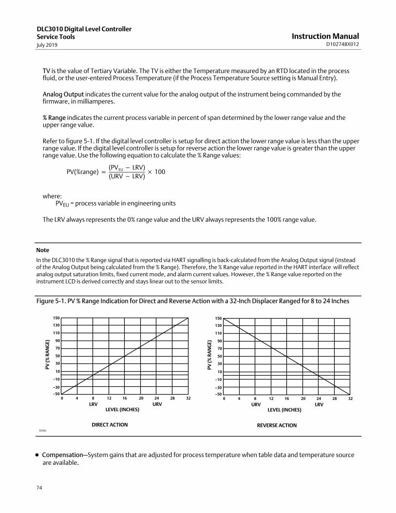
Instruction ManualD102748X012
DLC3010 Digital Level ControllerService ToolsJuly 2019
74
TV is the value of Tertiary Variable. The TV is either the Temperature measured by an RTD located in the processfluid, or the user-entered Process Temperature (if the Process Temperature Source setting is Manual Entry).
Analog Output indicates the current value for the analog output of the instrument being commanded by thefirmware, in milliamperes.
% Range indicates the current process variable in percent of span determined by the lower range value and theupper range value.
Refer to figure 5‐1. If the digital level controller is setup for direct action the lower range value is less than the upperrange value. If the digital level controller is setup for reverse action the lower range value is greater than the upperrange value. Use the following equation to calculate the % Range values:
PV(%range) �(PVEU � LRV)
(URV � LRV)� 100
where:��PVEU = process variable in engineering units
The LRV always represents the 0% range value and the URV always represents the 100% range value.
Note
In the DLC3010 the % Range signal that is reported via HART signalling is back-calculated from the Analog Output signal (insteadof the Analog Output being calculated from the % Range). Therefore, the % Range value reported in the HART interface will reflectanalog output saturation limits, fixed current mode, and alarm current values. However, the % Range value reported on theinstrument LCD is derived correctly and stays linear out to the sensor limits.
Figure 5‐1. PV % Range Indication for Direct and Reverse Action with a 32‐Inch Displacer Ranged for 8 to 24 Inches
DIRECT ACTION REVERSE ACTION
150
130
110
90
70
50
30
10
–10
–30
–500 4 8 12 16 20 24 28 32
LRV URVLEVEL (INCHES)
PV
(%
RA
NG
E)
150
130
110
90
70
50
30
10
–10
–30
–500 4 8 12 16 20 24 28 32
LRVURVLEVEL (INCHES)
PV
(%
RA
NG
E)
E0383
� Compensation—System gains that are adjusted for process temperature when table data and temperature sourceare available.
Instruction ManualD102748X012
DLC3010 Digital Level ControllerService Tools
July 2019
75
Compensated Torque Rate is the torque rate adjusted for process temperature by table data.
Note
At firmware 8 the table is not applied dynamically, so Compensated Torque Rate = Torque Rate.
Upper Fluid Density is adjusted for process temperature by user-entered table (SG). Upper Fluid Density is not usedwhen PV is Liquid Level; it represents density of upper process fluid when PV is Interface Level.
Lower Fluid Density is adjusted for process temperature by user-entered table (SG). Lower Fluid Density representsthe difference between densities of lower and upper process fluids when PV is Liquid Level; it represents Density ofLower Fluid when PV is Interface Level.
� The Signal Tracing menu can help isolate configuration issues by using variable help and/or the signal block diagram(provided in hosts that can present images), to work through the math.
Constants
Zero Reference Angle is the lever angle used as a reference point in PV calculation (deg). It represents the lowestmeasurable process condition when PV is Liquid Level; it represents the dry displacer condition when PV is InterfaceLevel or Liquid Density.
Note
If the driver rod is on the lower travel stop at dry condition, use Liquid Level as the PV and the difference between densities of lowerand upper process fluids for Lower Fluid Density.
Driver Rod Length is the recorded driver length (in).
Mechanical Gain is the mechanical gain of the sensor (lbf/deg).= CompensatedTorqueRate / DriverRod
Displacer Weight is the recorded weight (lb).
Dry Deflection is the theoretical torque tube deflection from zero load for dry displacer (deg). = DisplacerWeight * DriverRod / CompensatedTorqueRate
Displacer Volume is the recorded volume (in3).
Reference Buoyancy is the theoretical buoyant force (lb) generated when the displacer is completely covered withwater (SG = 1)= DisplacerVolume * ReferenceDensity
Displacer Length is the recorded length (in).
Level Offset is the Primary Variable value you want the instrument to report when physical level is at the bottom ofdisplacer. Unless you want the digital range to start at the vessel zero reference or the process set point, use zero forthis value. Level Offset is available only in Level or Interface mode. It is read-only in display and may be edited in the'Set Level Offset' menu item.
Signals are dynamic values of intermediate calculations in the PV signal path.
Sensor Rotation is the measurement of the pilot shaft rotation, referenced to the neutral (locked) position of thelever assembly, (deg).

Instruction ManualD102748X012
DLC3010 Digital Level ControllerService ToolsJuly 2019
76
Rotation Change is the change in torque tube deflection from Zero Reference Angle (deg).
Buoyant Force is the currently measured Buoyant Force (lbf).= Rotation Change * Mechanical Gain
Apparent SG is the apparent Specific Gravity (SG).= BuoyantForce / ReferenceBuoyancy
Preliminary PV is the Displacer Volume covered by liquid (in3).= BuoyantForce / FluidDensity
Scaled PV is the displacer length covered by lower fluid (in).= DisplacerLength *(BuoyantForce/DisplacerVolume -UpperFluidDensity)/(LowerFluidDensity-UpperFluidDensity)
Final PV = ScaledPV + LevelOffset + DisplacerRise (in), when PV is Liquid Level or Interface Level. �� � = ReferenceDensity * ApparentSG (lb/in3), when PV is Liquid Density.
� Electronics Monitors are variables tracked by hardware alert monitors.
Input Circuit contains the signal and diagnostics menu.
Hall Sensor Signal is the output of the Hall sensor signal amplifier. The valid range is 300 to 960 mV.
If slightly out of range, the lever is on/near travel stop. Check to see if: The displacer is removed, the instrument coupled with the displacer is removed, or if there is a severely bent orbroken flexure.
If 1230 mV, the Hall sensor input circuit is open or shorted to the high side.
If very erratic at steady process condition, the transducer circuit card is bad.
Hall Sensor Drive is the diagnostic measurement of the Hall sensor bias current, usually near 725 uA.
Processor is the execution cycle diagnostics menu.
Free Time Remaining is the unused portion of microprocessor execution period.
Writes Remaining is the Non-Volatile Memory life cycle diagnostics menu.
Configuration NVM is the remaining writes available to the microprocessor NVM (configuration data). TheConfiguration NVM writes start at 10,000 and is decremented for each write.
Transducer NVM is the remaining writes available to the sensor board NVM (factory characterization data). TheTransducer NVM writes start at 65,535 and is decremented for each write.
Buffer NVM is the remaining writes available to the electronics module NVM (buffer for firmware upgrades). TheBuffer NVM writes start at 65,535 and is decremented for each write.
Liquid Level / Interface Level / or Liquid Density
(PV gauge)
Instrument Temperature
(SV gauge) Indicates the current Instrument Temperature.
Process Temperature
(TV gauge) Indicates the current Process Temperature.

Instruction ManualD102748X012
DLC3010 Digital Level ControllerService Tools
July 2019
77
Analog Output
(mA gauge) Indicates the current value for the analog output of the instrument being commanded by the firmware, inmilliamperes.
% Range
(span gauge) Indicates the current process variable in percent of span determined by the lower range value and theupper range value.
Trends
Field Communicator Service Tools > Trends (3-3)
� PV (time-base strip chart)
� SV (time-base strip chart)
� TV (time-base strip chart) (appears if RTD is installed)
MaintenanceField Communicator Service Tools > Maintenance (3-4)
Tests
LCD Test— only visible if LCD Configuration is installed
The meter activates all segments immediately after power‐up, during a digital level controller self‐test, or during amaster reset sent by a host supporting HART communications. You can also test the meter by selecting Turn Cells Onto turn on all display segments, including the analog output bar graph, or select Turn Cells Off to turn off all displaysegments. When finished with the test, press OK to return the meter to normal display mode.
Loop Test— used to verify the controller output, the integrity of the loop, and the operations of any recorders or similardevices installed in the loop. To initiate a loop test, perform the following procedure:
1. Connect a reference meter to the controller. To do so, either connect the meter to the test connections inside theterminal box (see the Test Connections procedure) or connect the meter in the loop as shown in figure 2‐9.
2. Access Loop Test.
3. Select OK after you set the control loop to manual.
The Field Communicator displays the loop test menu.
4. Select a discreet milliamp level for the controller to output. At the “Choose analog output” prompt, select 4 mA, 20 mA, or Other to manually input a value between 4 and 20 milliamps.
5. Check the reference meter to verify that it reads the value you commanded the controller to output. If the readingsdo not match, either the controller requires an output trim, or the meter is malfunctioning.
After completing the test procedure, the display returns to the loop test screen and allows you to choose anotheroutput value or end the test.
Primary Calibration
The following contains a brief overview of the Full and Partial Calibration procedures. Refer to the Calibration section,starting on page 58, for detailed calibration information.
Instruction ManualD102748X012
DLC3010 Digital Level ControllerService ToolsJuly 2019
78
Full Calibration
� Min/Max Calibration is useful when process values can't be precisely observed, but the displacer can sequentially besubmerged in fluids of known minimum and maximum density. (E.g., no sight glass is available, but the cage can beisolated and drained or flooded.)
� Two Point Calibration uses independent observations of two valid process conditions, together with the hardwaredimensional data and SG information, to compute the effective torque rate and zero reference angle for the sensor.
� Weight Calibration may be used on the bench or with a calibration jig that is capable of applying a mechanical forceto the driver rod to simulate displacer buoyancy changes. It allows the instrument and sensor to be calibrated usingequivalent weights or force inputs instead of using the actual displacer buoyancy changes.
Partial Calibration
� Capture Zero captures the current value of the torque tube angle as the input zero.
� Trim Gain operations recompute gain with one observation of process data.
� Trim Zero computes the value of the input angle required to align the digital Primary Variable with the user’sobservation of the process, and corrects the stored input zero reference, assuming that the calibration gain isaccurate. Use this procedure when the process cannot be moved to zero for capture, but gain is known to becorrect (only a bias error exists).
Secondary Calibration
The following contains a brief overview of the Secondary Calibration procedures. Refer to the Calibration section,starting on page 58, for detailed calibration information.
Temperature Calibration allows you to display the temperature as measured by the instrument. You can then trim thetemperature reading so that it matches the actual temperature more closely in the region of interest. (This is an offsetadjustment only. There is no ability to change the gain.)
Analog Output Calibration allows trimming the gain and offset of the Digital‐to‐Analog (D/A) converter to adjust theaccuracy at which the output follows 4 to 20 mA current commands from the firmware. This relationship is initially setin the factory, and should not require frequent user adjustment.
Reset/Restore
Restore Factory Defaults
� Restore Factory Configuration— Follow the prompts on the Field Communicator display to restore the digitallevel controller to the factory configuration.
� Restore Factory Compensation— Replaces all calibration and compensation data with factory defaults.
Both Restore Factory Configuration and Restore Factory are drastic procedures which should be used only as a lastresort.
Reset Device issues a master reset request to the processor in the DLC3010.

Instruction ManualD102748X012
DLC3010 Digital Level ControllerMaintenance & Troubleshooting
July 2019
79
Section 6 Maintenance & Troubleshooting6‐6‐
The DLC3010 digital level controller features a modular design for easy maintenance. If you suspect a malfunction,check for an external cause before performing the diagnostics described in this section.
Sensor parts are subject to normal wear and must be inspected and replaced as necessary. For sensor maintenanceinformation, refer to the appropriate sensor instruction manual.
WARNING
To avoid personal injury, always wear protective gloves, clothing, and eyewear when performing any maintenanceoperations.
Personal injury or property damage due to sudden release of pressure, contact with hazardous fluid, fire, or explosion canbe caused by puncturing, heating, or repairing a displacer that is retaining process pressure or fluid. This danger may notbe readily apparent when disassembling the sensor or removing the displacer. Before disassembling the sensor orremoving the displacer, observe the appropriate warnings provided in the sensor instruction manual.
Check with your process or safety engineer for any additional measures that must be taken to protect against processmedia.
CAUTION
When replacing components, use only components specified by the factory. Always use proper component replacementtechniques, as presented in this manual. Improper techniques or component selection may invalidate the approvals andthe product specifications, as indicated in table 1‐1. It may also impair operations and the intended function of the device.
Diagnostic Messages In addition to the output, the LCD meter displays abbreviated diagnostic messages for troubleshooting the digitallevel controller. To accommodate two‐word messages, the display alternates between the first and second word. Themeter displays messages simultaneously on the Process Variable and Process Variable Unit lines as shown in figure 6‐1.Messages on the Process Variable line refer to general device conditions, while messages on the Process Variable Unitline refer to specific causes for these conditions. A description of each diagnostic message follows.
� [BLANK]— If the meter does not appear to function, and the instrument is otherwise functioning correctly, makesure the digital level controller is configured for the LCD meter. The meter will not function if the LCD Configurationselection is “Not Installed.” To check this function, connect the Field Communicator to the digital level controllerand turn it on. From the Online menu, select:Configure > Manual Setup > Instrument Display > LCD Configuration (2-2-7-1) For information on setting up the LCD meter see page 49. A diagnostic test for meter function is also detailed laterin this section.

Instruction ManualD102748X012
DLC3010 Digital Level ControllerMaintenance & TroubleshootingJuly 2019
80
Figure 6‐1. LCD Meter Diagnostic Display
DIAGNOSTICMESSAGE
PROCESS VARIABLE VALUE
MODE
ANALOG DISPLAY OF OUTPUT
E0380
� FAIL HDWR— This message indicates the existence of one or more of the following conditions:
��—The primary sensor input conversion is out of range.
��—The primary sensor drive current is out of range.
��—The internal reference voltage for controlling the loop current is out of range.
Perform the diagnostic procedures detailed later in this section to isolate the specific failure. If diagnostics indicate afailure of a particular module, replace the indicated module with a new one. Otherwise, correct the mechanical inputcondition to clear the message.
� OFLOW— The location of the decimal point, as configured in the meter setup, is not compatible with the value to bedisplayed by the meter. For example, if the meter is measuring a level greater that 99.999 mm, and the meterdecimal point is set to 3 digit precision, the meter will display an “OFLOW” message because it is only capable ofdisplaying a maximum value of 99.999 when set to 3 digit precision. The position of the decimal point may beadjusted by using the Field Communicator. From the Online menu, select:Configure > Manual Setup > Instrument Display > Decimal Places (2-2-7-4).Selecting “0” will put the display in auto‐scale mode. (The number of decimal places displayed will be the maximumremaining in the display field for the current value of PV.)
Hardware Diagnostics If you suspect a malfunction despite the absence of diagnostic messages on the Field Communicator display, followthe procedures described in table 6‐1 to verify that the digital level controller hardware and process connections are ingood working order. Under each of the major symptoms, specific suggestions are offered for solving problems. Alwaysdeal with the most likely and easiest‐to‐check conditions first.
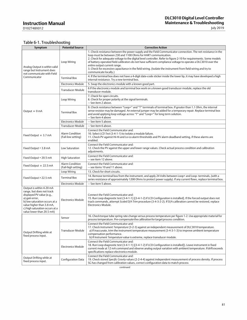
Instruction ManualD102748X012
DLC3010 Digital Level ControllerMaintenance & Troubleshooting
July 2019
81
Table 6‐1. TroubleshootingSymptom Potential Source Corrective Action
Analog Output is within validrange but Instrument doesnot communicate with FieldCommunicator
Loop Wiring
1. Check resistance between the power supply and the Field Communicator connection. The net resistance in theloop must be between 230 and 1100 Ohms for HART communication.2. Check for adequate voltage to the digital level controller. Refer to figure 2‐10 for requirements. Some modelsof battery‐operated field calibrators do not have sufficient compliance voltage to operate a DLC3010 over theentire output current range.3. Check for excessive capacitance in the field wiring. (Isolate the instrument from field wiring and try tocommunicate locally.)
Terminal Box4. If the terminal box does not have a 4‐digit date‐code sticker inside the lower lip, it may have developed a highinternal resistance. Try a new terminal box.
Electronics Module 5. Swap the electronics module with a known good part.
Transducer Module6 If the electronics module and terminal box work on a known good transducer module, replace the oldtransducer module.
Output � 0 mA
Loop Wiring7. Check for open circuits.8. Check for proper polarity at the signal terminals.— See item 2 above.
Terminal Box
9. Check resistance between “Loop+” and “T” terminals of terminal box. If greater than 1.1 Ohm, the internalsense resistor may be damaged. An external jumper may be added for a temporary repair. Replace terminal boxand avoid applying loop voltage across “T” and “Loop+” for long term solution.— See item 4 above
Electronics Module — See item 5 above.
Transducer Module — See item 6 above.
Fixed Output � 3.7 mAAlarm Condition(Fail‐low setting)
Connect the Field Communicator and:10. Select LCD Test (3-4-1-1) to isolate a module failure.11. Check PV against Hi‐Hi and Lo‐Lo alarm thresholds and PV alarm deadband setting, if these alarms areenabled.
Fixed Output = 3.8 mA Low SaturationConnect the Field Communicator and:12. Check the PV against the upper and lower range values. Check actual process condition and calibrationadjustments.
Fixed Output = 20.5 mA High SaturationConnect the Field Communicator and:— see item 12 above.
Fixed Output � 22.5 mAAlarm Condition(Fail‐high setting)
Connect the Field Communicator and:— see items 10 and 11 above.
Fixed Output > 22.5 mA
Loop Wiring 13. Check for short circuits.
Terminal Box14. Remove terminal box from the instrument, and apply 24 Volts between Loop+ and Loop- terminals, (with aseries resistance of approximately 1200 Ohms to protect power supply). If any current flows, replace terminal box.
Electronics Module — See item 5 above.
Output is within 4-20 mArange, but does not trackdisplayed PV value (e.g.,a) gain error,b) low saturation occurs at avalue higher than 3.8 mA,c) high saturation occurs at avalue lower than 20.5 mA)
Electronics Module
Connect the Field Communicator and:15. Run Loop diagnostic test (3-4-1-1) [(3-4-1-2) if LCD Configuration is installed]. If the forced output does nottrack commands, attempt Scaled D/A Trim procedure (3‐4-3-2-2). If D/A calibration cannot be restored, replaceElectronics Module.
Output Drifting while atfixed process input.
Sensor16. Check torque tube spring rate change versus process temperature per figure 1‐2. Use appropriate material forprocess temperature. Pre‐compensate the calibration for target process condition.
Transducer Module
Connect the Field Communicator and:17. Check Instrument Temperature (3‐2-3) against an independent measurement of DLC3010 temperature. a) If inaccurate, trim the instrument temperature measurement (3-4-3-1-3) to improve ambient temperaturecompensation performance. b) If Instrument Temperature value is extreme, replace transducer module.
Electronics Module
Connect the Field Communicator and:18. Run Loop diagnostic test (3-4-1-1) [(3-4-1-2) if LCD Configuration is installed]). Leave instrument in fixedcurrent mode at 12 mA command and observe analog output variation with ambient temperature. If drift exceedsspecifications replace electronics module.
Output Drifting while atfixed process input.
Configuration DataConnect the Field Communicator and:19. Check stored Specific Gravity values (2-2-4-4) against independent measurement of process density. If processSG has changed from calibration values, correct configuration data to match process
continued
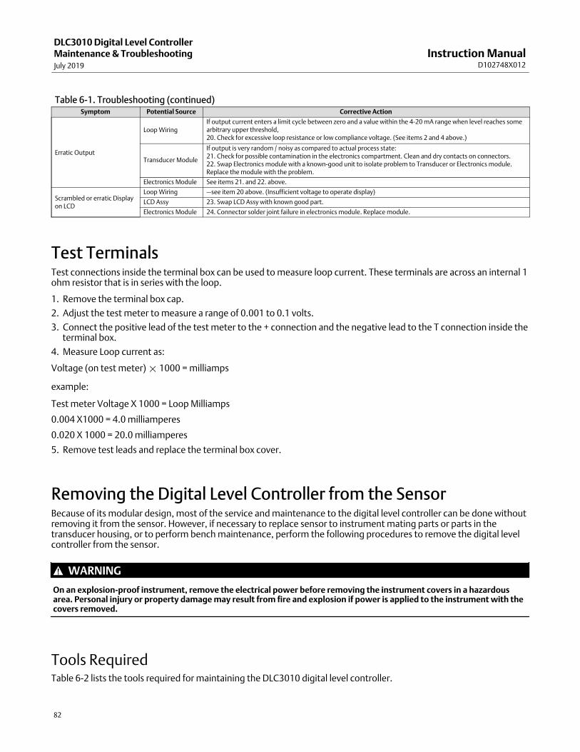
Instruction ManualD102748X012
DLC3010 Digital Level ControllerMaintenance & TroubleshootingJuly 2019
82
Table 6‐1. Troubleshooting (continued)Symptom Potential Source Corrective Action
Erratic Output
Loop WiringIf output current enters a limit cycle between zero and a value within the 4-20 mA range when level reaches somearbitrary upper threshold,20. Check for excessive loop resistance or low compliance voltage. (See items 2 and 4 above.)
Transducer Module
If output is very random / noisy as compared to actual process state:21. Check for possible contamination in the electronics compartment. Clean and dry contacts on connectors.22. Swap Electronics module with a known-good unit to isolate problem to Transducer or Electronics module.Replace the module with the problem.
Electronics Module See items 21. and 22. above.
Scrambled or erratic Displayon LCD
Loop Wiring —see item 20 above. (Insufficient voltage to operate display)
LCD Assy 23. Swap LCD Assy with known good part.
Electronics Module 24. Connector solder joint failure in electronics module. Replace module.
Test Terminals Test connections inside the terminal box can be used to measure loop current. These terminals are across an internal 1ohm resistor that is in series with the loop.
1. Remove the terminal box cap.
2. Adjust the test meter to measure a range of 0.001 to 0.1 volts.
3. Connect the positive lead of the test meter to the + connection and the negative lead to the T connection inside theterminal box.
4. Measure Loop current as:
Voltage (on test meter) � 1000 = milliamps
example:
Test meter Voltage X 1000 = Loop Milliamps
0.004 X1000 = 4.0 milliamperes
0.020 X 1000 = 20.0 milliamperes
5. Remove test leads and replace the terminal box cover.
Removing the Digital Level Controller from the SensorBecause of its modular design, most of the service and maintenance to the digital level controller can be done withoutremoving it from the sensor. However, if necessary to replace sensor to instrument mating parts or parts in thetransducer housing, or to perform bench maintenance, perform the following procedures to remove the digital levelcontroller from the sensor.
WARNING
On an explosion‐proof instrument, remove the electrical power before removing the instrument covers in a hazardousarea. Personal injury or property damage may result from fire and explosion if power is applied to the instrument with thecovers removed.
Tools RequiredTable 6‐2 lists the tools required for maintaining the DLC3010 digital level controller.
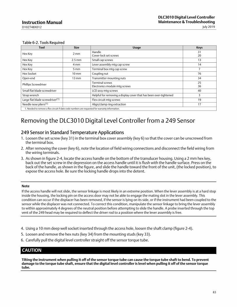
Instruction ManualD102748X012
DLC3010 Digital Level ControllerMaintenance & Troubleshooting
July 2019
83
Table 6‐2. Tools RequiredTool Size Usage Keys
Hex Key 2 mmHandleCover‐lock set screws
3120
Hex Key 2.5 mm Small cap screws 13
Hex Key 4 mm Lever assembly mtg cap screw 14
Hex Key 5 mm Terminal box mtg cap screw 7
Hex Socket 10 mm Coupling nut 76
Open‐end 13 mm Transmitter mounting nuts 34
Phillips ScrewdriverTerminal screwsElectronics module mtg screws
2536
Small flat blade screwdriver LCD assy mtg screws 40
Strap wrench Helpful for removing a display cover that has been over‐tightened 3
Large flat blade screwdriver(1) Flex circuit mtg screws 19
Needle nose pliers(1) Align/clamp ring extraction 17
1. Needed to remove a flex circuit if date code numbers are requested for warranty information.
Removing the DLC3010 Digital Level Controller from a 249 Sensor
249 Sensor in Standard Temperature Applications1. Loosen the set screw (key 31) in the terminal box cover assembly (key 6) so that the cover can be unscrewed from
the terminal box.
2. After removing the cover (key 6), note the location of field wiring connections and disconnect the field wiring fromthe wiring terminals.
3. As shown in figure 2‐4, locate the access handle on the bottom of the transducer housing. Using a 2 mm hex key,back out the set screw in the depression on the access handle until it is flush with the handle surface. Press on theback of the handle, as shown in the figure, and slide the handle toward the front of the unit, (the locked position), toexpose the access hole. Be sure the locking handle drops into the detent.
Note
If the access handle will not slide, the sensor linkage is most likely in an extreme position. When the lever assembly is at a hard stopinside the housing, the locking pin on the access door may not be able to engage the mating slot in the lever assembly. Thiscondition can occur if the displacer has been removed, if the sensor is lying on its side, or if the instrument had been coupled to thesensor while the displacer was not connected. To correct this condition, manipulate the sensor linkage to bring the lever assemblyto within approximately 4 degrees of the neutral position before attempting to slide the handle. A probe inserted through the topvent of the 249 head may be required to deflect the driver rod to a position where the lever assembly is free.
4. Using a 10 mm deep well socket inserted through the access hole, loosen the shaft clamp (figure 2‐4).
5. Loosen and remove the hex nuts (key 34) from the mounting studs (key 33).
6. Carefully pull the digital level controller straight off the sensor torque tube.
CAUTION
Tilting the instrument when pulling it off of the sensor torque tube can cause the torque tube shaft to bend. To preventdamage to the torque tube shaft, ensure that the digital level controller is level when pulling it off of the sensor torquetube.
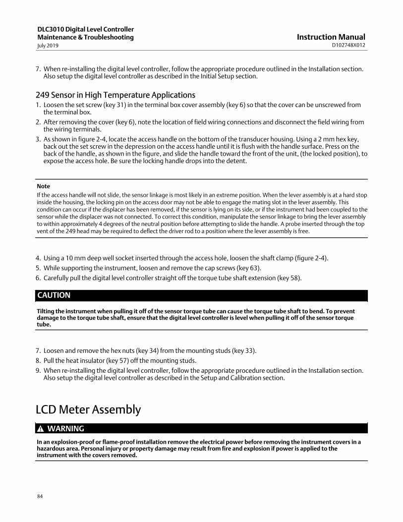
Instruction ManualD102748X012
DLC3010 Digital Level ControllerMaintenance & TroubleshootingJuly 2019
84
7. When re‐installing the digital level controller, follow the appropriate procedure outlined in the Installation section.Also setup the digital level controller as described in the Initial Setup section.
249 Sensor in High Temperature Applications1. Loosen the set screw (key 31) in the terminal box cover assembly (key 6) so that the cover can be unscrewed from
the terminal box.
2. After removing the cover (key 6), note the location of field wiring connections and disconnect the field wiring fromthe wiring terminals.
3. As shown in figure 2‐4, locate the access handle on the bottom of the transducer housing. Using a 2 mm hex key,back out the set screw in the depression on the access handle until it is flush with the handle surface. Press on theback of the handle, as shown in the figure, and slide the handle toward the front of the unit, (the locked position), toexpose the access hole. Be sure the locking handle drops into the detent.
Note
If the access handle will not slide, the sensor linkage is most likely in an extreme position. When the lever assembly is at a hard stopinside the housing, the locking pin on the access door may not be able to engage the mating slot in the lever assembly. Thiscondition can occur if the displacer has been removed, if the sensor is lying on its side, or if the instrument had been coupled to thesensor while the displacer was not connected. To correct this condition, manipulate the sensor linkage to bring the lever assemblyto within approximately 4 degrees of the neutral position before attempting to slide the handle. A probe inserted through the topvent of the 249 head may be required to deflect the driver rod to a position where the lever assembly is free.
4. Using a 10 mm deep well socket inserted through the access hole, loosen the shaft clamp (figure 2‐4).
5. While supporting the instrument, loosen and remove the cap screws (key 63).
6. Carefully pull the digital level controller straight off the torque tube shaft extension (key 58).
CAUTION
Tilting the instrument when pulling it off of the sensor torque tube can cause the torque tube shaft to bend. To preventdamage to the torque tube shaft, ensure that the digital level controller is level when pulling it off of the sensor torquetube.
7. Loosen and remove the hex nuts (key 34) from the mounting studs (key 33).
8. Pull the heat insulator (key 57) off the mounting studs.
9. When re‐installing the digital level controller, follow the appropriate procedure outlined in the Installation section.Also setup the digital level controller as described in the Setup and Calibration section.
LCD Meter Assembly
WARNING
In an explosion‐proof or flame‐proof installation remove the electrical power before removing the instrument covers in ahazardous area. Personal injury or property damage may result from fire and explosion if power is applied to theinstrument with the covers removed.
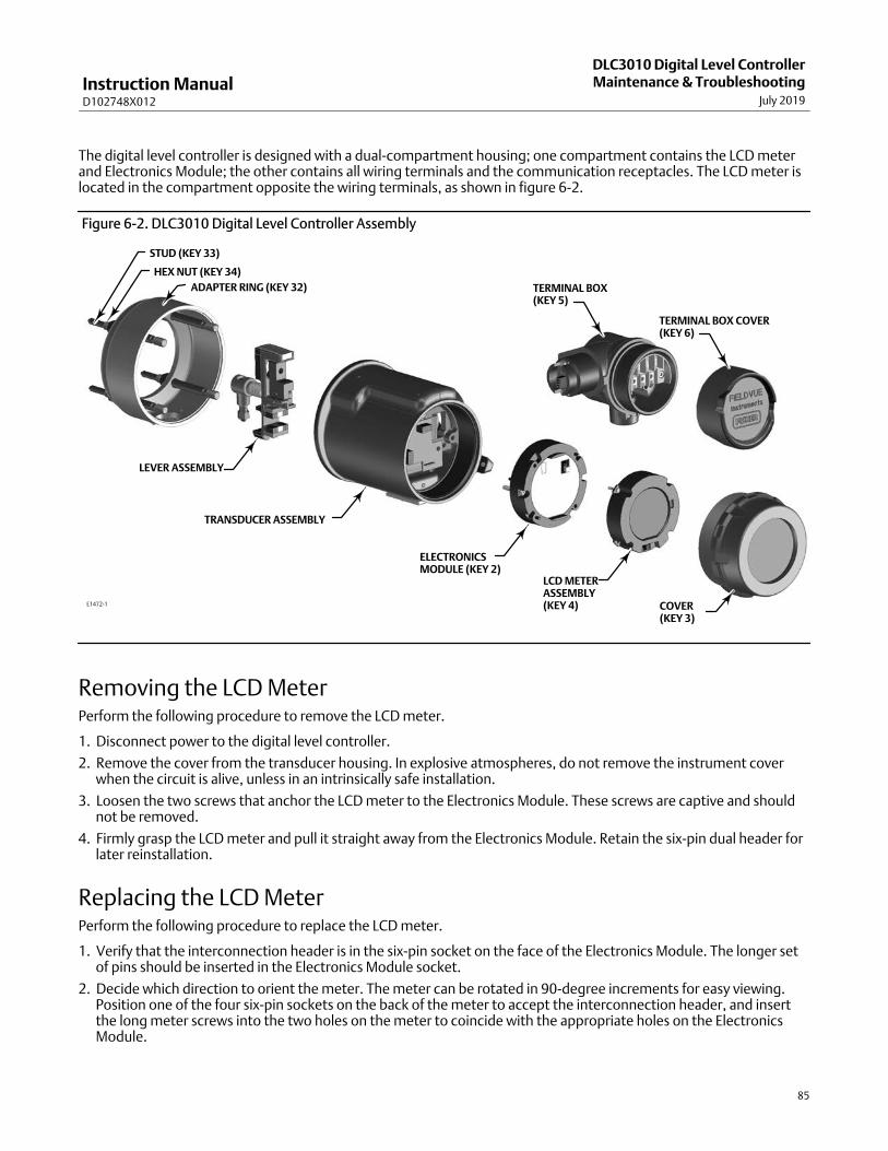
Instruction ManualD102748X012
DLC3010 Digital Level ControllerMaintenance & Troubleshooting
July 2019
85
The digital level controller is designed with a dual‐compartment housing; one compartment contains the LCD meterand Electronics Module; the other contains all wiring terminals and the communication receptacles. The LCD meter islocated in the compartment opposite the wiring terminals, as shown in figure 6‐2.
E1472-1
Figure 6‐2. DLC3010 Digital Level Controller Assembly
COVER(KEY 3)
LCD METERASSEMBLY(KEY 4)
ELECTRONICSMODULE (KEY 2)
TRANSDUCER ASSEMBLY
TERMINAL BOX(KEY 5)
TERMINAL BOX COVER(KEY 6)
LEVER ASSEMBLY
ADAPTER RING (KEY 32)
HEX NUT (KEY 34)
STUD (KEY 33)
Removing the LCD Meter Perform the following procedure to remove the LCD meter.
1. Disconnect power to the digital level controller.
2. Remove the cover from the transducer housing. In explosive atmospheres, do not remove the instrument coverwhen the circuit is alive, unless in an intrinsically safe installation.
3. Loosen the two screws that anchor the LCD meter to the Electronics Module. These screws are captive and shouldnot be removed.
4. Firmly grasp the LCD meter and pull it straight away from the Electronics Module. Retain the six‐pin dual header forlater reinstallation.
Replacing the LCD Meter Perform the following procedure to replace the LCD meter.
1. Verify that the interconnection header is in the six‐pin socket on the face of the Electronics Module. The longer setof pins should be inserted in the Electronics Module socket.
2. Decide which direction to orient the meter. The meter can be rotated in 90‐degree increments for easy viewing.Position one of the four six‐pin sockets on the back of the meter to accept the interconnection header, and insertthe long meter screws into the two holes on the meter to coincide with the appropriate holes on the ElectronicsModule.

Instruction ManualD102748X012
DLC3010 Digital Level ControllerMaintenance & TroubleshootingJuly 2019
86
3. Attach the meter to the interconnection pins. Thread the long meter screws into the holes on the ElectronicsModule and tighten to secure the meter.
4. Note the position of the alarm jumper on the LCD meter removed from the digital level controller. Remove thealarm jumper and install it on the replacement meter in the same position.
5. Install the six‐pin dual header on the LCD meter. Carefully insert the LCD meter to mate with the interconnectingpins with the receptacles on the Electronics Module .
CAUTION
To prevent damage to the interconnecting pins when installing the LCD Meter, use the guide pins to insert the LCD meterstraight onto the Electronics Module, without twisting or turning.
6. Replace the cover. Tighten 1/3 of a revolution after the cover begins to compress the O‐ring. Both instrumentcovers must be fully engaged to meet explosion‐proof or flame‐proof requirements.
Electronics Module
Removing the Electronics Module Perform the following procedure to remove the Electronics Module.
Note
The electronics are sealed in a moisture‐proof plastic enclosure referred to as the Electronics Module. The assembly is anon‐repairable unit; if a malfunction occurs the entire unit must be replaced.
WARNING
On an explosion‐proof instrument, remove the electrical power before removing the instrument covers in a hazardousarea. Personal injury or property damage may result from fire and explosion if power is applied to the instrument with thecovers removed.
1. Disconnect power to the digital level controller.
2. Remove the cover from the transducer housing. In explosive atmospheres, do not remove the instrument coverwhen the circuit is alive, unless in an intrinsically safe installation. Remove the LCD meter assembly.
3. Loosen the two screws that anchor the Electronics Module to the transducer housing. These screws are captive andshould not be removed.
4. Firmly grasp the Electronics Module and pull it straight out of the housing.
Replacing the Electronics Module Perform the following procedure to replace the Electronics Module.
1. Carefully insert the Electronics Module to mate the interconnecting pins with the receptacles on the Transducerhousing.

Instruction ManualD102748X012
DLC3010 Digital Level ControllerMaintenance & Troubleshooting
July 2019
87
CAUTION
To prevent damage to the interconnecting pins when installing the Electronics Module, use the guide pins to insert theElectronics Module straight onto the Transducer housing receptacles without twisting or turning.
2. Tighten the two mounting screws. Replace the LCD meter assembly.
3. Replace the cover. Tighten 1/3 of a revolution after the cover begins to compress the O‐ring. Both instrumentcovers must be fully engaged to meet explosion‐proof requirements.
Terminal BoxThe terminal box is located on the transducer housing and contains the terminal strip assembly for field wiringconnections. Unless indicated otherwise, refer to figure 7‐3.
WARNING
On an explosion‐proof instrument, remove the electrical power before removing the instrument covers in a hazardousarea. Personal injury or property damage may result from fire and explosion if power is applied to the instrument with thecovers removed.
Removing the Terminal Box1. Loosen the set screw (key 31) in the terminal box cover assembly (key 6) so that the cover can be unscrewed from
the terminal box.
2. After removing the cover (key 6), note the location of field wiring connections and disconnect the field wiring fromthe wiring terminals.
3. Remove the screw (key 7), and pull out the terminal box assembly.
CAUTION
To avoid damaging the terminal box assembly connector, pull the terminal box assembly straight out of the housing,without twisting or turning.
Replacing the Terminal Box
Note
Inspect all O‐rings for wear and replace as necessary.

Instruction ManualD102748X012
DLC3010 Digital Level ControllerMaintenance & TroubleshootingJuly 2019
88
1. Apply sealant to the O‐ring (key 27) and install the O‐ring over the stem of the terminal box as shown in figure 7‐3.
2. Orient the terminal box so that the connectors engage properly, and carefully insert the terminal box into thetransducer housing until the O‐ring is seated.
CAUTION
To avoid damaging the mating pins in the Transducer housing, ensure that the guiding mechanism is engaged properlybefore applying force.
3. Fasten the terminal box to the transducer housing with the screw (key 7). Tighten the screw to 6 N�m (53 lbf�in).
4. Apply sealant to the O‐ring (key 26) and install the O‐ring over the cover threads on the terminal box. Use a tool toprevent cutting the O‐ring while installing it over the threads.
5. Reconnect the field wiring as noted in step 2 in the Removing the Terminal Box procedure.
6. Apply lubricant to the threads on the terminal box to prevent seizing or galling while installing the terminal boxcover.
7. Screw the terminal box cover assembly (key 6) completely onto the terminal box to seat the O‐ring (key 26). Loosenthe cover (not more than 1 turn) until the set screw (key 31) aligns with one of the recesses in the terminal boxbeneath the cover. Tighten the set screw to engage the recesses but no more than 0.88 N�m (7.8 lbf�in).
8. Apply lubricant to the conduit entrance plug (key 28) and install it in the unused conduit entrance.
Removing and Replacing the Inner Guide and Access HandleAssemblyThe access handle and inner guide are located on the transducer housing. Unless indicated otherwise, refer to figure 7‐2.
1. Remove the digital level controller from the sensor as described in Removing the Digital Level Controller from the Sensor.
2. Loosen and remove the hex nuts (key 34) from the studs (key 33) and remove the adapter ring (key 32).
Note
In the next step the screws (key 13) will be attracted by the magnets on the lever assembly. Use care to keep the screws fromfalling beneath the coupling shield.
3. Remove the coupling shield (key 16) by removing the two screws (key 13). Take care not to drop the screws into thelever assembly compartment where they will be attracted by the magnets.
4. Loosen and remove the two screws (key 13) in the handle assembly (key 12). Remove the handle assembly and theinner guide (key 11).
5. Apply thread lock to the internal threads of the replacement inner guide. Also apply a thin coat of a light grade ofgrease to the zero locking pin on the inner guide and on the surface that is opposite the zero locking pin, as shownin figure 6‐3 (this surface contacts the transducer housing when installed).
6. Place the inner guide in the slot inside the transducer housing so that the vent holes in the inner guide (the milledslots in the inner guide, see figure 6‐3) face the exterior of the housing and are over the access hole.

Instruction ManualD102748X012
DLC3010 Digital Level ControllerMaintenance & Troubleshooting
July 2019
89
Figure 6‐3. Installing Inner Guide and Access Handle Assembly
ZERO LOCKING PININNER GUIDE(KEY 11)
VENT HOLE
LUBRICATETHIS SURFACE
VENT HOLES
HANDLEASSEMBLY(KEY 12)
SCREWS (KEY 13)
LUBRICATETHIS SURFACE
TRANSDUCERHOUSING
ACCESS HOLEE0381
7. Apply a thin coat of a light grade of grease to the surface of the replacement handle assembly (see figure 6‐3) whereit will contact the transducer housing.
8. Install the handle assembly (key 12) in the slot of the transducer housing over the inner guide (key 11) so that thevent holes in the handle assembly are over the access hole.
9. Install two screws (key 13) to secure the handle assembly (key 12) to the inner guide (key 11). Tighten the screws to 0.48 N�m (4.2 lbf�in).
10. Press down on the handle as shown in figure 2‐4 and slide it forward to make sure it works smoothly and that thezero locking pin engages the lever assembly. Also check for free travel of the lever assembly when the handle is inthe unlocked position.
11. Install the coupling shield (key 16) and secure with the two screws (key 13). Tighten the screws to 0.48 N�m (4.2 lbf�in).
12. Refer to figure 7‐1. Install the adapter ring (key 32) on the studs (key 33) and secure with hex nuts (key 34).
13. When re‐installing the digital level controller, follow the appropriate procedure outlined in the Installation section.Also setup the digital level controller as described in the Setup and Calibration section.
Lever Assembly
Removing the Lever AssemblyThe lever assembly is located in the transducer housing. Unless indicated otherwise, refer to figure 7‐2.
1. Remove the digital level controller from the sensor as described in Removing the Digital Level Controller from theSensor.
2. Loosen and remove the hex nuts (key 34) from the studs (key 33) and remove the adapter ring (key 32).
3. Remove the coupling shield (key 16) by removing the two screws (key 13). Take care not to drop the screws into thelever assembly compartment where they will be attracted by the magnets.

Instruction ManualD102748X012
DLC3010 Digital Level ControllerMaintenance & TroubleshootingJuly 2019
90
4. Inspect the lever assembly alignment with the housing. If it is off center or not co‐axial with the main housing,continue with the removal procedure.
5. Loosen and remove the mounting screw (key 14) from the lever assembly.
6. Loosen the flexure block from its machined pocket in the housing, by inserting a smooth tool into the hole for themounting screw, and gently rocking it back and forth in what would be the vertical axis if the transmitter wereinstalled.
7. Lift the lever assembly out of the housing.
Inspect the flexure for damage. If the flexure is bent or torn, replace the lever assembly.
Replacing the Lever AssemblyReplacing the lever assembly in the field may result in a slight degradation in linearity performance, since the factorycharacterizes the entire transducer module as a unit. For most applications, this degradation should not be noticeable.(If guaranteed restoration to factory specification is desired, the entire transducer module should be replaced.)
1. Move the zero‐pin slide to the locking position.
2. Apply a thin coat of a light grade of grease to the internal thread of the hole for the lever mounting bolt.
3. Hold lever assembly by coupling block and guide the flexure block into its aligning slot in the housing withoutapplying any downward force to the sprung parts of the lever assembly.
CAUTION
To prevent damage to the flexure when inserting the flexure block into its aligning slot in the housing, apply pressure tothe flexure block only.
A long pin inserted into the bolt‐hole in the flexure block may be used to pull it against the inside corner of the aligningslot.
4. Secure the block by reinstalling the M5x20 socket‐head cap screw (key 14). Torque to 2.8 N�m (25 lbf�in) �10%.
5. Mark bolt head and block with a movement‐detecting sealant.
6. Install the coupling shield (key 16) and secure with the two screws (key 13). Tighten the screws to 0.48 N�m (4.2 lbf�in).
7. Refer to figure 7‐1. Install the adapter ring (key 32) on the studs (key 33) and secure with hex nuts (key 34). Whenre‐installing the digital level controller, follow the appropriate procedure outlined in the Installation section. Set upthe digital level controller as described in the Setup and Calibration section.
Packing for ShipmentIf it becomes necessary to return the unit for repair or diagnosis, contact your Emerson sales office for returned goodsinformation.
CAUTION
Lock the lever assembly when shipping the stand‐alone instrument, to prevent damage to the flexure.
Use the original shipping carton if possible.
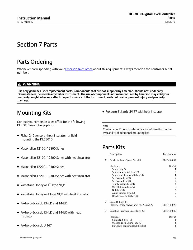
Instruction ManualD102748X012
DLC3010 Digital Level ControllerParts
July 2019
91
Section 7 Parts7‐7‐
Parts Ordering Whenever corresponding with your Emerson sales office about this equipment, always mention the controller serialnumber.
WARNING
Use only genuine Fisher replacement parts. Components that are not supplied by Emerson, should not, under anycircumstances, be used in any Fisher instrument. The use of components not manufactured by Emerson may void yourwarranty, might adversely affect the performance of the instrument, and could cause personal injury and propertydamage.
Mounting Kits
Contact your Emerson sales office for the followingDLC3010 mounting options:
� Fisher 249 sensors - heat insulator for fieldmounting the DLC3010
� Masoneilan 12100, 12800 Series
� Masoneilan 12100, 12800 Series with heat insulator
� Masoneilan 12200, 12300 Series
� Masoneilan 12200, 12300 Series with heat insulator
� Yamatake Honeywell� Type NQP
� Yamatake Honeywell Type NQP with heat insulator
� Foxboro‐Eckardt 134LD and 144LD
� Foxboro‐Eckardt 134LD and 144LD with heatinsulator
� Foxboro‐Eckardt LP167
� Foxboro‐Eckardt LP167 with heat insulator
Note
Contact your Emerson sales office for information on theavailability of additional mounting kits.
Parts Kits Description Part Number
��1* Small Hardware Spare Parts Kit 19B1643X052
Includes Qty/kit
Screw (key 7) 1
Screw, hex socket (key 13) 6
Screw, cap, hex socket (key 14) 1
Set Screw (key 20) 2
Set Screw (key 31) 2
Test Terminal (key 24) 4
Wire Retainer (key 25) 8
Nut (key 34) 4
Alarm Jumper (key 35) 2
Header Assembly (key 38) 2
��2* Spare O‐Rings Kit
Includes three each of keys 21, 26, and 27 19B1643X022
��3* Coupling Hardware Spare Parts Kit 19B1643X042
Includes Qty/kit
Clamp Nut (key 76) 1
Washer, Lock, Spring (key 77) 1
Bolt, lock, coupling block(key 82) 1
*Recommended spare parts

Instruction ManualD102748X012
DLC3010 Digital Level ControllerPartsJuly 2019
92
Parts List
Note
Contact your Emerson sales office for Part Ordering information.
DLC3010 Digital Level Controllers(figure 7‐1)
Key Description
�1 Transducer Module(1)
�2* Electronics Ass'y(1)
Key Description Part Number
�3 Cover Assy, includes O‐ring (key 21)
�4 LCD Meter Ass'y, includes alarm jumper (key 35),
header ass'y (key 38) and captive screws (key 40),
and LCD Meter ass'y 28B5738X022
�5* Terminal Box Ass'y 28B5740X022
�6 Terminal Box Cover Ass'y, includes labels
(key 30 and 64) and set screw (key 31)
�7 Screw, hex socket(2)
�8 Nameplate
�9 Drive Screw
21* O‐ring(3)
32 Adaptor Ring
33 Stud (4 req'd)
34 Hex Nut (4 req'd)
35 Alarm Jumper(2)(4)(5)
36 Screw, captive
For electronics ass'y (2 req'd)(4)
38 Header Assembly, dual row (not shown)(2)(4)(5)
40 Screw, captive
For LCD meter (2 req'd)(5)
66 Anti‐Seize Sealant (not furnished with instrument)
67 Thread locking adhesive (medium strength)
(not furnished with instrument)
70 Lithium grease (not furnished with instrument)
NOTES: 1� INSTALL ALARM JUMPER (KEY 35) ON ELECTRONICS ASSEMBLY (KEY2) WHEN LCD METER (KEY 4) IS NOT INSTALLED. 2� LOCATION OF ALARM JUMPER (KEY 35) WHEN LCD METER (KEY 4) IS INSTALLED.
1
2
58B5510‐E
APPLY LUB/THREADLOCK
Figure 7‐1. DLC3010 Digital Level Controller Assembly
*Recommended spare parts
1. These parts are not replaced in the field due to serialization andcharacterization issues, but can be replaced at a qualified service center or FisherAuthorized Service Provider (FASP) that can issue nameplate. Contact yourEmerson sales office for additional information.2. Included in small hardware spare parts kit.3. Included in spare O‐rings kit.4. Included in the Electronics Ass'y, key 25. Included in the LCD Meter Ass'y. key 4

Instruction ManualD102748X012
DLC3010 Digital Level ControllerParts
July 2019
93
Key Description Part Number
Transducer Assembly (figure 7‐2)11 Inner Guide
12 Handle Ass'y
13 Screw, hex socket (4 req'd)
14 Screw, cap
15* Lever Assembly 38B5509X042
16 Coupling Shield
17 Ring, align/clamp
Key Description
19 Machine Screw, pan head
20 Set Screw(2)
31 Set Screw, hex socket(2)
67 Thread Locking adhesive (medium strength)
(not furnished with instrument)
68 Sealant
76 Clamp Nut(2)(6)
77 Spring Lock Washer(2)(6)
79 Transducer Board Assembly(1)
80 Hall Guard
81 Compound, silicone
82 Bolt, lock, coupling block(6)
Figure 7‐2. DLC3010 Digital Level Controller Transducer Assembly
GE18497 31
77
76
82
*Recommended spare parts
1. These parts are not replaced in the field due to serialization and characterizationissues, but can be replaced at a qualified service center or Fisher Authorized ServiceProvider (FASP) that can issue nameplate. Contact your Emerson sales office for additional information.2. Included in small hardware spare parts kit.6. Included in Coupling Hardware Spare Parts Kit
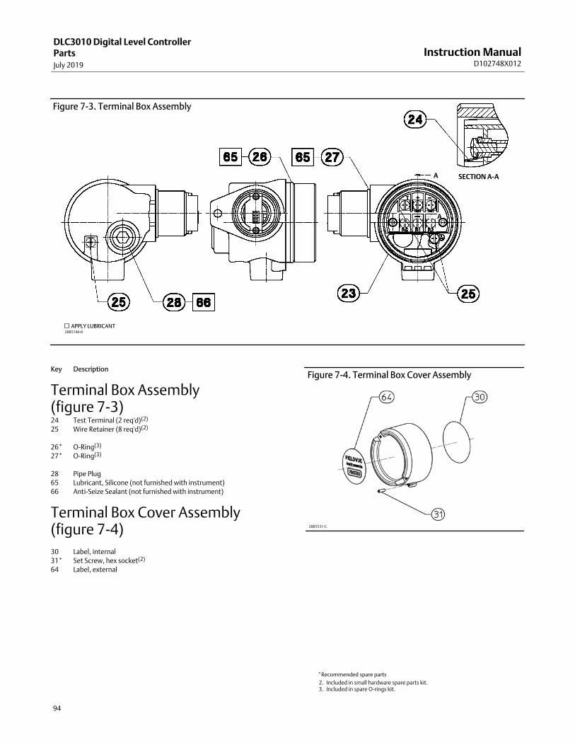
Instruction ManualD102748X012
DLC3010 Digital Level ControllerPartsJuly 2019
94
Figure 7‐3. Terminal Box Assembly
28B5740-B
APPLY LUBRICANT
SECTION A‐AA
A
Key Description
Terminal Box Assembly(figure 7‐3)24 Test Terminal (2 req'd)(2)
25 Wire Retainer (8 req'd)(2)
26* O‐Ring(3)
27* O‐Ring(3)
28 Pipe Plug
65 Lubricant, Silicone (not furnished with instrument)
66 Anti‐Seize Sealant (not furnished with instrument)
Terminal Box Cover Assembly(figure 7‐4)
30 Label, internal
31* Set Screw, hex socket(2)
64 Label, external
Figure 7‐4. Terminal Box Cover Assembly
28B5531‐C
*Recommended spare parts
2. Included in small hardware spare parts kit.3. Included in spare O‐rings kit.

Instruction ManualD102748X012
DLC3010 Digital Level ControllerParts
July 2019
95
Figure 7‐5. Mounting Kit for 249 Sensors with Heat Insulator
28B5741‐A
Mounting Parts
These parts are available as a kit as indicated in theMounting Kits section. Contact your Emerson salesoffice for these mounting options.
Key Description
249 Sensors with Heat Insulator (figure 7‐5)57 Heat Insulator
58 Shaft Extension
59 Shaft Coupling
60 Set Screw, hex socket (2 req'd)
61 Screw, hex hd (4 req'd)
78 Washer, plain (4 req'd)
Key Description
Masoneilan Sensors (figures 7‐6 and 7‐7)12100 or 12800 without Heat Insulator
58 Shaft Extension
59 Shaft Coupling
60 Set Screw, hex socket (2 req'd)
61 Screw, hex hd (4 req'd)
62 Mounting Adapter
63 Screw, hex socket, (4 req'd)
12100 or 12800 with Heat Insulator
57 Heat Insulator
58 Shaft Extension
59 Shaft Coupling
60 Set Screw, hex socket (2 req'd)
61 Screw, hex hd (4 req'd)
62 Mounting Adapter
63 Screw, hex socket (4 req'd)
78 Washer, plain (4 req'd)

Instruction ManualD102748X012
DLC3010 Digital Level ControllerPartsJuly 2019
96
Figure 7‐6. Mounting Kit for Masoneilan 12200 and 12300 Sensor without Heat Insulator
29B8444‐A
Figure 7‐7. Mounting Kit for Masoneilan 12200 and 12300 Sensor with Heat Insulator
29B8445‐A
Key Description
12200 or 12300 without Heat Insulator
58 Shaft Extension
59 Shaft Coupling,
60 Hex Socket Screw (2 req'd)
62 Mounting Adaptor
74 Hex Nut (4 req'd)
75 Hex Cap Screw (4 req'd)
Key Description
12200 or 12300 with Heat Insulator
57 Heat Insulator
58 Shaft Extension
59 Shaft Coupling
61 Hex Cap Screw (4 req'd)
60 Hex Socket Screw (2 req'd)
62 Mounting Adaptor
74 Hex Nut (4 req'd)
75 Hex Cap Screw (4 req'd)
78 Washer, plain (4 req'd) not shown

Instruction ManualD102748X012
DLC3010 Digital Level ControllerParts
July 2019
97
Key Description
Yamatake NQP Sensor
Without Heat Insulator
58 Shaft Extension
59 Shaft Retainer
60 Hex Socket Screw
62 Mounting Adaptor
63 Hex Socket Screw (3 req'd)
71 Hex Socket Screw (3 req'd)
72 Shaft Adapter
73 Hex Socket Screw (2 req'd)
With Heat Insulator
57 Heat Insulator
58 Shaft Extension
59 Shaft Retainer
60 Hex Socket Screw
61 Hex Cap Screw (4 req'd)
62 Mounting Adaptor
63 Hex Socket Screw (3 req'd)
71 Hex Socket Screw (3 req'd)
72 Shaft Adapter
73 Hex Socket Screw (2 req'd)
78 Washer, plain (4 req'd)
Key Description
Foxboro‐Eckardt Sensors
144LD without Heat Insulator
58 Shaft Extension
59 Shaft Coupling
60 Set Screw, hex socket (2 req'd)
62 Mounting Adapter
74 Hex Nut (4 req'd)
75 Hex Cap Screw, steel (4 req'd)
144LD with Heat Insulator
57 Heat Insulator
58 Shaft Extension
59 Shaft Coupling
60 Set Screw, hex socket (2 req'd)
61 Screw, hex hd (4 req'd)
62 Mounting Adapter
74 Hex Nut (4 req'd)
75 Hex Cap Screw (4 req'd)
78 Washer, plain (4 req'd)
LP167 without Heat Insulator
58 Shaft Extension
59 Shaft Coupling
60 Set Screw, hex socket (2 req'd)
62 Mounting Adapter
63 Screw, hex socket, (4 req'd)

Instruction ManualD102748X012
DLC3010 Digital Level ControllerPartsJuly 2019
98

Instruction ManualD102748X012
DLC3010 Digital Level ControllerPrinciple of Operation
July 2019
99
Appendix A Principle of OperationA‐
HART Communication The HART (Highway Addressable Remote Transducer) protocol gives field devices the capability of communicatinginstrument and process data digitally. This digital communication occurs over the same two‐wire loop that providesthe 4-20 mA process control signal, without disrupting the process signal. In this way, the analog process signal, withits faster update rate, can be used for control. At the same time, the HART protocol allows access to digital diagnostic,maintenance, and additional process data. The protocol provides total system integration via a host device.
The HART protocol uses the frequency shift keying (FSK) technique based on the Bell 202 communication standard. Bysuperimposing a frequency signal over the 4-20 mA current, digital communication is attained. Two individualfrequencies of 1200 and 2200 Hz are superimposed as a sinewave over the 4-20 mA current loop. These frequenciesrepresent the digits 1 and 0 (see figure A‐1). The average value of this sinewave is zero, therefore no DC value is addedto the 4-20 mA signal. Thus, true simultaneous communication is achieved without interrupting the process signal.
Figure A‐1. HART Frequency Shift Keying Technique
-0.5 mA
+0.5 mA
1200 Hz“1”
2200 Hz“0”
AVERAGE CURRENT CHANGE DURING COMMUNICATION = 0
ANALOGSIGNAL
0
A6174
The HART protocol allows the capability of multidropping, networking several devices to a single communications line.This process is well suited for monitoring remote applications such as pipelines, custody transfer sites, and tank farms.
Multidrop Communication“Multidropping” refers to the connection of several digital level controllers or transmitters to a single communicationstransmission line. Communication between the host and the field instruments takes place digitally with the analogoutput of the instruments deactivated. With the HART communications protocol, up to 15 field instruments can beconnected on a single twisted pair of wires or over leased phone lines. Multidrop installations are not recommendedwhere intrinsic safety is a requirement.
The application of a multidrop installation requires consideration of the update rate necessary from each instrument,the combination of instrument models, and the length of the transmission line. Communication with the fieldinstruments can be accomplished with commercially available Bell 202 modems and a host implementing the HARTprotocol. Each instrument is identified by a unique address (1-15) and responds to the commands defined in the HARTprotocol.
Figure A‐2 shows a typical multidrop network. Do not use this figure as an installation diagram. Contact your Emersonsales office with specific requirements for multidrop applications.

Instruction ManualD102748X012
DLC3010 Digital Level ControllerPrinciple of OperationJuly 2019
100
Figure A‐2. Typical Multidropped Network
HOST
BELL 202MODEM
POWERSUPPLY
LOAD
The Field Communicator can test, configure, and format a multidropped DLC3010 digital level controller in the sameway as in a standard point‐to‐point installation, provided that it has been configured to scan for multiple pollingaddresses.
Note
DLC3010 digital level controllers are set to address 0 at the factory, allowing them to operate in the standard point‐to‐pointmanner with a 4-20 mA output signal. To activate multidrop communication, the address must be changed to a number between1 and 15. This change deactivates the 4-20 mA analog output, sending it to 4 mA. The failure mode current also is disabled.
Digital Level Controller Operation The DLC3010 digital level controller is a loop‐powered instrument that measure changes in liquid level, level of aninterface between two liquids, or density of a liquid. Changes in the buoyancy of a displacer suspended in a vessel varythe load on a torque tube. The displacer and torque tube assembly constitute the primary mechanical sensor. Theangular deflection of the torque tube is measured by the instrument transducer, which consists of a magnet systemmoving over a Hall effect device. A liquid crystal display (LCD) meter can display the analog output; process variable(level, interface level, or density); the process temperature, if an RTD (resistance temperature detector) is installed;the degrees of torque tube rotation; and percent range.
The instrument uses a microcontroller and associated electronic circuitry to measure the process variable, provide acurrent output, drive the LCD meter, and provide HART communications capability. Figure A‐3 shows the digital levelcontroller assembly. Figure A‐4 is a block diagram of the main components in the instrument electronics; the LCDmeter, the processor module, the transducer board, and the terminal board. The processor module contains themicroprocessor, the analog‐to‐digital (A/D) converters, loop interface, signal conditioning, the digital‐to‐analog (D/A)output, power supply and interfaces to other boards.
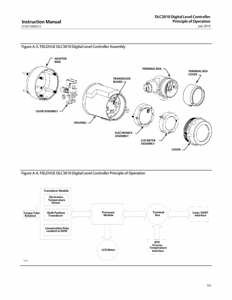
Instruction ManualD102748X012
DLC3010 Digital Level ControllerPrinciple of Operation
July 2019
101
Figure A‐3. FIELDVUE DLC3010 Digital Level Controller Assembly
LCD METERASSEMBLY
ELECTRONICSASSEMBLY
LEVER ASSEMBLY
TERMINAL BOXTERMINAL BOX COVER
HOUSING
COVER
ADAPTERRING
TRANSDUCERBOARD
Figure A‐4. FIELDVUE DLC3010 Digital Level Controller Principle of Operation
LCD Meter
Transducer Module
ProcessorModule
Torque TubeRotation
Linearization Dataresident in NVM
TerminalBox
RTDProcess
TemperatureInterface
Loop / HARTInterface
ElectronicsTemperature
Shaft PositionTransducer
Sensor
E0378

Instruction ManualD102748X012
DLC3010 Digital Level ControllerPrinciple of OperationJuly 2019
102
The transducer board contains the Hall sensor, a temperature sensor to monitor the Hall sensor temperature, and anEEPROM to store the coefficients associated with the Hall sensor. The terminal board contains the EMI filters, the loopconnection terminals, and the connections for the optional RTD used to measure process temperature.
A level, density, or interface level change in the measured fluid causes a change in the displacer position (figure A‐5).This change is transferred to the torque tube assembly. As the measured fluid changes, the torque tube assemblyrotates up to 4.4 degrees for a 249 sensor, varying the digital level controller output between 4 and 20 mA.
Figure A‐5. Typical Sensor Operation
TORQUETUBE
DISPLACER
249 SENSOR (SIDE VIEW)W1389‐1
The rotary motion of the torque tube is transferred to the digital level controller lever assembly. The rotary motionmoves a magnet attached to the lever assembly, changing the magnetic field that is sensed by the Hall effect sensor.The sensor converts the magnetic field signal to an electronic signal.
The microcontroller accepts the electronic signal, which is ambient‐temperature‐compensated and linearized. Themicrocontroller can also actively compensate for changes in liquid specific gravity due to changes in processtemperature based on an input via HART protocol or via an optional RTD, if it is connected. The D/A output circuitaccepts the microcontroller output and provides a 4 to 20 mA current output signal.
During normal operation, when the input is between the lower and upper range values, the digital level controlleroutput signal ranges between 4 and 20 mA and is proportional to the input. See figure A‐6. If the input should exceedthe lower and upper range values, the output will continue to be proportional to the input until the output reacheseither 3.8 or 20.5 mA. At this time the output is considered saturated and will remain at this value until the inputreturns to the normal operating range. However, should an alarm occur, the output is driven to either 3.7 or 22.5 mA,depending upon the position of the alarm jumper.
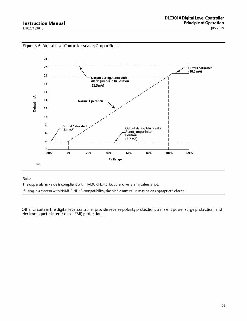
Instruction ManualD102748X012
DLC3010 Digital Level ControllerPrinciple of Operation
July 2019
103
Figure A‐6. Digital Level Controller Analog Output Signal
2
4
6
8
10
12
14
16
18
20
22
24
-20% 0% 20% 40% 60% 80% 100% 120%
Output during Alarm withAlarm Jumper in Hi Position
Output Saturated(3.8 mA)
(22.5 mA)
Output during Alarm withAlarm Jumper in LoPosition(3.7 mA)
Output Saturated(20.5 mA)
Normal Operation
Ou
tpu
t (m
A)
PV Range
E0379
Note
The upper alarm value is compliant with NAMUR NE 43, but the lower alarm value is not.
If using in a system with NAMUR NE 43 compatibility, the high alarm value may be an appropriate choice.
Other circuits in the digital level controller provide reverse polarity protection, transient power surge protection, andelectromagnetic interference (EMI) protection.

Instruction ManualD102748X012
DLC3010 Digital Level ControllerPrinciple of OperationJuly 2019
104
Instruction ManualD102748X012
DLC3010 Digital Level ControllerField Communicator Menu Tree
July 2019
105
Appendix B Fast-Key Sequence and Field CommunicatorMenu TreeB‐B‐0Fast-key sequences are included for common DLC3010 digital level controller functions. Also included are FieldCommuniator menu trees.
� Fast-key sequences, see table B‐1
� Hot Key menu, see figure B‐1
� Overview menu, see figure B‐2
� Guided Setup menu, see figure B‐3
� Manual Setup menu, see figure B‐4
� Alert Setup menu, see figure B‐5
� Calibration menu, see figure B‐6
� Service Tools menu, see figure B‐7
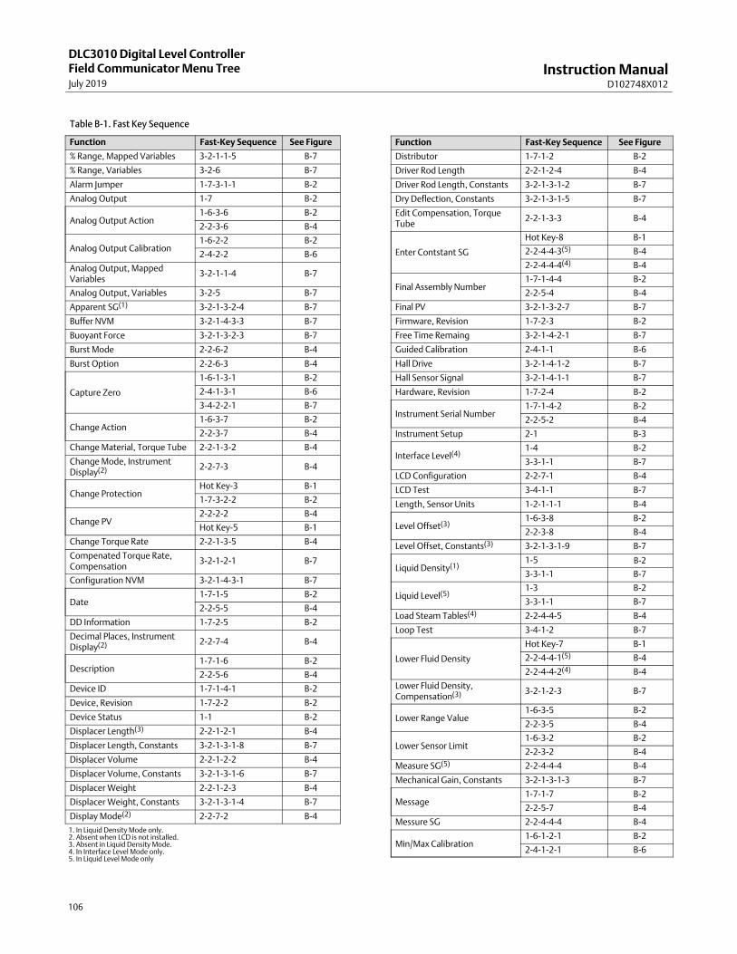
Instruction ManualD102748X012
DLC3010 Digital Level ControllerField Communicator Menu TreeJuly 2019
106
Table B‐1. Fast Key Sequence
Function Fast-Key Sequence See Figure
% Range, Mapped Variables 3-2-1-1-5 B‐7
% Range, Variables 3-2-6 B‐7
Alarm Jumper 1-7-3-1-1 B‐2
Analog Output 1-7 B‐2
Analog Output Action1-6-3-6 B‐2
2-2-3-6 B‐4
Analog Output Calibration1-6-2-2 B‐2
2-4-2-2 B‐6
Analog Output, MappedVariables
3-2-1-1-4 B‐7
Analog Output, Variables 3-2-5 B‐7
Apparent SG(1) 3-2-1-3-2-4 B‐7
Buffer NVM 3-2-1-4-3-3 B‐7
Buoyant Force 3-2-1-3-2-3 B‐7
Burst Mode 2-2-6-2 B‐4
Burst Option 2-2-6-3 B‐4
Capture Zero
1-6-1-3-1 B‐2
2-4-1-3-1 B‐6
3-4-2-2-1 B‐7
Change Action1-6-3-7 B‐2
2-2-3-7 B‐4
Change Material, Torque Tube 2-2-1-3-2 B‐4
Change Mode, InstrumentDisplay(2) 2-2-7-3 B‐4
Change ProtectionHot Key-3 B‐1
1-7-3-2-2 B‐2
Change PV2-2-2-2 B‐4
Hot Key-5 B‐1
Change Torque Rate 2-2-1-3-5 B‐4
Compenated Torque Rate,Compensation
3-2-1-2-1 B‐7
Configuration NVM 3-2-1-4-3-1 B‐7
Date1-7-1-5 B‐2
2-2-5-5 B‐4
DD Information 1-7-2-5 B‐2
Decimal Places, InstrumentDisplay(2) 2-2-7-4 B‐4
Description1-7-1-6 B‐2
2-2-5-6 B‐4
Device ID 1-7-1-4-1 B‐2
Device, Revision 1-7-2-2 B‐2
Device Status 1-1 B‐2
Displacer Length(3) 2-2-1-2-1 B‐4
Displacer Length, Constants 3-2-1-3-1-8 B‐7
Displacer Volume 2-2-1-2-2 B‐4
Displacer Volume, Constants 3-2-1-3-1-6 B‐7
Displacer Weight 2-2-1-2-3 B‐4
Displacer Weight, Constants 3-2-1-3-1-4 B‐7
Display Mode(2) 2-2-7-2 B‐4
Function Fast-Key Sequence See Figure
Distributor 1-7-1-2 B‐2
Driver Rod Length 2-2-1-2-4 B‐4
Driver Rod Length, Constants 3-2-1-3-1-2 B‐7
Dry Deflection, Constants 3-2-1-3-1-5 B‐7
Edit Compensation, TorqueTube
2-2-1-3-3 B‐4
Enter Contstant SG
Hot Key-8 B‐1
2-2-4-4-3(5) B‐4
2-2-4-4-4(4) B‐4
Final Assembly Number1-7-1-4-4 B‐2
2-2-5-4 B‐4
Final PV 3-2-1-3-2-7 B‐7
Firmware, Revision 1-7-2-3 B‐2
Free Time Remaing 3-2-1-4-2-1 B‐7
Guided Calibration 2-4-1-1 B‐6
Hall Drive 3-2-1-4-1-2 B‐7
Hall Sensor Signal 3-2-1-4-1-1 B‐7
Hardware, Revision 1-7-2-4 B‐2
Instrument Serial Number1-7-1-4-2 B‐2
2-2-5-2 B‐4
Instrument Setup 2-1 B‐3
Interface Level(4)1-4 B‐2
3-3-1-1 B‐7
LCD Configuration 2-2-7-1 B‐4
LCD Test 3-4-1-1 B‐7
Length, Sensor Units 1-2-1-1-1 B‐4
Level Offset(3)1-6-3-8 B‐2
2-2-3-8 B‐4
Level Offset, Constants(3) 3-2-1-3-1-9 B‐7
Liquid Density(1)1-5 B‐2
3-3-1-1 B‐7
Liquid Level(5)1-3 B‐2
3-3-1-1 B‐7
Load Steam Tables(4) 2-2-4-4-5 B‐4
Loop Test 3-4-1-2 B‐7
Lower Fluid Density
Hot Key-7 B‐1
2-2-4-4-1(5) B‐4
2-2-4-4-2(4) B‐4
Lower Fluid Density,Compensation(3) 3-2-1-2-3 B‐7
Lower Range Value1-6-3-5 B‐2
2-2-3-5 B‐4
Lower Sensor Limit1-6-3-2 B‐2
2-2-3-2 B‐4
Measure SG(5) 2-2-4-4-4 B‐4
Mechanical Gain, Constants 3-2-1-3-1-3 B‐7
Message1-7-1-7 B‐2
2-2-5-7 B‐4
Messure SG 2-2-4-4-4 B‐4
Min/Max Calibration1-6-1-2-1 B‐2
2-4-1-2-1 B‐6
1. In Liquid Density Mode only.2. Absent when LCD is not installed.3. Absent in Liquid Density Mode.4. In Interface Level Mode only.5. In Liquid Level Mode only
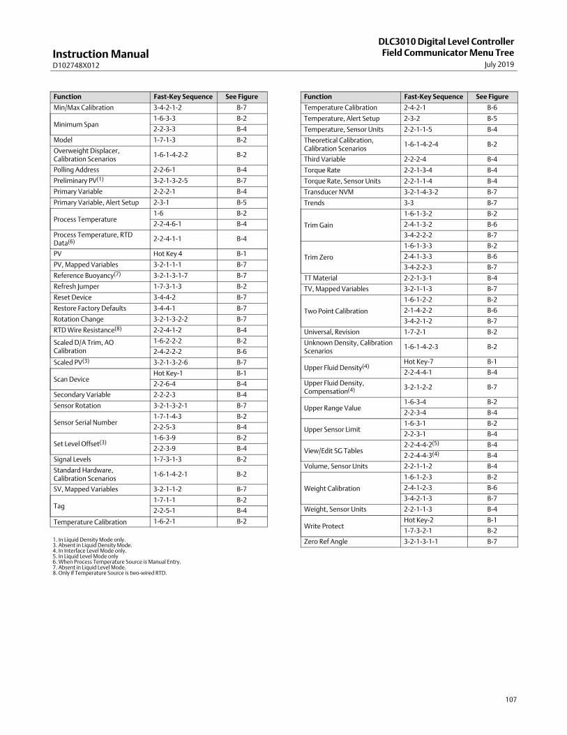
Instruction ManualD102748X012
DLC3010 Digital Level ControllerField Communicator Menu Tree
July 2019
107
Function Fast-Key Sequence See Figure
Min/Max Calibration 3-4-2-1-2 B‐7
Minimum Span1-6-3-3 B‐2
2-2-3-3 B‐4
Model 1-7-1-3 B‐2
Overweight Displacer,Calibration Scenarios
1-6-1-4-2-2 B‐2
Polling Address 2-2-6-1 B‐4
Preliminary PV(1) 3-2-1-3-2-5 B‐7
Primary Variable 2-2-2-1 B‐4
Primary Variable, Alert Setup 2-3-1 B‐5
Process Temperature1-6 B‐2
2-2-4-6-1 B‐4
Process Temperature, RTDData(6) 2-2-4-1-1 B‐4
PV Hot Key 4 B‐1
PV, Mapped Variables 3-2-1-1-1 B‐7
Reference Buoyancy(7) 3-2-1-3-1-7 B‐7
Refresh Jumper 1-7-3-1-3 B‐2
Reset Device 3-4-4-2 B‐7
Restore Factory Defaults 3-4-4-1 B‐7
Rotation Change 3-2-1-3-2-2 B‐7
RTD Wire Resistance(8) 2-2-4-1-2 B‐4
Scaled D/A Trim, AOCalibration
1-6-2-2-2 B‐2
2-4-2-2-2 B‐6
Scaled PV(3) 3-2-1-3-2-6 B‐7
Scan DeviceHot Key-1 B‐1
2-2-6-4 B‐4
Secondary Variable 2-2-2-3 B‐4
Sensor Rotation 3-2-1-3-2-1 B‐7
Sensor Serial Number1-7-1-4-3 B‐2
2-2-5-3 B‐4
Set Level Offset(3)1-6-3-9 B‐2
2-2-3-9 B‐4
Signal Levels 1-7-3-1-3 B‐2
Standard Hardware,Calibration Scenarios
1-6-1-4-2-1 B‐2
SV, Mapped Variables 3-2-1-1-2 B‐7
Tag1-7-1-1 B‐2
2-2-5-1 B‐4
Temperature Calibration 1-6-2-1 B‐2
Function Fast-Key Sequence See Figure
Temperature Calibration 2-4-2-1 B‐6
Temperature, Alert Setup 2-3-2 B‐5
Temperature, Sensor Units 2-2-1-1-5 B‐4
Theoretical Calibration,Calibration Scenarios
1-6-1-4-2-4 B‐2
Third Variable 2-2-2-4 B‐4
Torque Rate 2-2-1-3-4 B‐4
Torque Rate, Sensor Units 2-2-1-1-4 B‐4
Transducer NVM 3-2-1-4-3-2 B‐7
Trends 3-3 B‐7
Trim Gain
1-6-1-3-2 B‐2
2-4-1-3-2 B‐6
3-4-2-2-2 B‐7
Trim Zero
1-6-1-3-3 B‐2
2-4-1-3-3 B‐6
3-4-2-2-3 B‐7
TT Material 2-2-1-3-1 B‐4
TV, Mapped Variables 3-2-1-1-3 B‐7
Two Point Calibration
1-6-1-2-2 B‐2
2-1-4-2-2 B‐6
3-4-2-1-2 B‐7
Universal, Revision 1-7-2-1 B‐2
Unknown Density, CalibrationScenarios
1-6-1-4-2-3 B‐2
Upper Fluid Density(4)Hot Key-7 B‐1
2-2-4-4-1 B‐4
Upper Fluid Density,Compensation(4) 3-2-1-2-2 B‐7
Upper Range Value1-6-3-4 B‐2
2-2-3-4 B‐4
Upper Sensor Limit1-6-3-1 B‐2
2-2-3-1 B‐4
View/Edit SG Tables2-2-4-4-2(5) B‐4
2-2-4-4-3(4) B‐4
Volume, Sensor Units 2-2-1-1-2 B‐4
Weight Calibration
1-6-1-2-3 B‐2
2-4-1-2-3 B‐6
3-4-2-1-3 B‐7
Weight, Sensor Units 2-2-1-1-3 B‐4
Write ProtectHot Key-2 B‐1
1-7-3-2-1 B‐2
Zero Ref Angle 3-2-1-3-1-1 B‐71. In Liquid Density Mode only.3. Absent in Liquid Density Mode.4. In Interface Level Mode only.5. In Liquid Level Mode only6. When Process Temperature Source is Manual Entry.7. Absent in Liquid Level Mode.8. Only if Temperature Source is two-wired RTD.

Instruction ManualD102748X012
DLC3010 Digital Level ControllerField Communicator Menu TreeJuly 2019
108
Figure B‐1. Hot Key
Hot Key
1 Scan Device2 Write Protect3 Change Protection4 PV5 Change PV6 Upper Fluid Density7 Lower Fluid Density8 Enter Contstant SG
Device Information
1 Identification2 Revisions3 Alarm Type and Security
Overview
1 Device Status2 Comm Status (see 2-2-6 in figure B‐4)3 Liquid Level�1
3 Interface Level�2
3 Liquid Density�3
4 Process Temperature5 Analog Output6 Calibration / Ranging7 Device Information
1
Alarm Type and Security
1 Alarm Configuration2 Security
Calibration / Ranging
1 Primary2 Secondary3 Ranging
Ranging
1 Upper Sensor Limit2 Lower Sensor Limit3 Minimum Span4 Upper Range Value5 Lower Range Value6 Analog Output Action7 Change Action8 Level Offset�5
9 Set Level Offset�5
Primary
1 Guided Calibration2 Full Calibration3 Partial Calibration4 Application Notes
Figure B‐2. Overview
Identification
1 Tag2 Distributor3 Model4 Serial Numbers5 Date6 Description7 Message 1‐7-1-4
1-7
Revisions
1 Universal2 Device3 Firmware4 Hardware5 DD Information
1‐7-3
Alarm Configuration
1 Alarm Jumper2 Refresh Jumper3 Signal Levels
Security
1 Write Protect2 Change Protection
1‐7-3-2
Device Status
1 Refresh Alerts2 No Active Alerts�4
1‐1
Serial Numbers
1 Device ID2 Instr Serial Num3 Sensor Serial Num4 Final Asmbly Num
Full Calibration
1 Min/Max Calibration2 Two Point Calibration3 Weight Calibration
Partial Calibration
1 Capture Zero2 Trim Gain3 Trim Zero
Secondary
1 Temperature Calibration2 Analog Output Calibration
Temperature Calibration
1 Instrument Temperature2 Instr Tmpr Offset3 Trim Inst Tmpr4 Process Temperature�6
5 Proc Tmpr Offset�6
62Trim Proc Tmpr�6
Analog Output Calibration
1 Analog Output2 Scaled D/A Trim
1-7-1
1-7-2
1‐7-3-1
1-6
1-6-1
1-6-1-2
1-6-1-3
1-6-2
1-6-3
NOTES:1� APPEARS IN LIQUID LEVEL MODE2� APPEARS IN INTERFACE LEVEL MODE3� APPEARS IN LIQUID DENSITY MODE4� ONLY APPEARS WHEN DEVICE STATUS IS “GOOD”. IF DEVICE STATUS IS NOT GOOD,5� THERE WILLL BE A MENU FOR EACH ACTIVE ALERT, WHICH WILL EXPAND TO SHOW 5� DESCRIPTIONS, CAUSES, AND RECOMMENDED ACTIONS FOR CLEARING THE ALERT.5� ABSENT IN LIQUID DENSITY MODE6� ABSENT WHEN TEMPERATURE SOURCE IS MANUAL ENTRY
Application Notes
1 Calibration Types2 Calibration Scenarios
Calibration Types
1 Precondition2 Full Calibration3 Partial Calibration
1-6-1-41-6-1-4-1
Calibration Scenarios
1 Standard Hardware2 Overweight Displacer3 Unknown Density4 Theoretical Calibration
1-6-1-4-2Standard Hardware
1 Background2 Precondition3 Procedure4 Validation5 Final Configuration
Theoretical Calibration
1 Background2 Procedure3 Final Configuration
Overweight Displacer
1 Background2 Precondition3 Procedure4 Final Configuration
1-6-1-4-2-1
1-6-1-4-2-2
1-6-1-4-2-31-6-2-2
1-6-2-1

Instruction ManualD102748X012
DLC3010 Digital Level ControllerField Communicator Menu Tree
July 2019
109
Figure B‐3. Configure > Guided Setup
Configure
1 Guided Setup2 Manual Setup3 Alert Setup4 Calibration
Guided Setup
1 Instrument Setup
2‐12
Process Conditions
1 RTD Data�2
2 Proc Temp Source3 Change Source4 Fluid�4
4 Fluids�5
5 Temperature6 Setting�6
Figure B‐4. Configure > Manual SetupSensor Units
1 Length 2 Volume3 Weight4 Torque Rate5 Temperature
Manual Setup
1 Sensor2 Variables3 Ranging4 Process Conditions5 Device Identification6 Communications7 Instrument Display
2‐2‐1
Variables
1 Primary Variable2 Change PV3 Secondary Variable4 Third Variable
Device Identification
1 Tag2 Instr Serial Num3 Sensor Serial Num4 Final Assembly Num5 Date6 Description7 Message
Sensor
1 Sensor Units2 Sensor Dimensions3 Torque Tube4 Instrument Mounting5 Sensor Damping
Sensor Dimensions
1 Displacer Length2 Displacer Volume3 Displacer Weight4 Driver Rod Length
Torque Tube
1 TT Material2 Change Material3 Edit Compensation4 Torque Rate5 Change Torque Rate
2‐2‐1-1 2‐2‐1-2
2‐2‐1-3
Instrument Display
1 LCD Configuration2 Display Mode�8
3 Change Mode�8
4 Decimal Places�8
2‐2‐7
Ranging
1 Upper Sensor Limit2 Lower Sensor Limit3 Minimum Span4 Upper Range Value5 Lower Range Value6 Analog Output Action7 Change Action8 Level Offset�1
9 Set Level Offset�1
2‐2‐2
2‐2‐3
2‐2‐5
2‐2‐4
Configure
1 Guided Setup2 Manual Setup3 Alert Setup4 Calibration
2‐2
2
Edit Compensation
1 TT Compensation2 Torque Comp Plot3 Pre-compensate Torque Rate
2‐2‐1-3-3
RTD Data� 2
1 Process Temperature2 RTD Wire Resistance�3
Fluid� 4
1 Lower Fluid Density2 View/Edit SG Tables3 Enter Constant SG4 Measure SG
View/Edit SG Tables
1 Fluid Table2 SG Comp Plot
Fluids�5
1 Upper Fluid Density2 Lower Fluid Density3 View/Edit SG Tables4 Enter Constant SG5 Load Steam Tables
View/Edit SG Tables
1 Upper Fluid Table2 Lower Fluid Table3 SG Comp Plot
Temperature Setting�6
1 Process Temperature�7
Communications
1 Polling Address2 Burst Mode3 Burst Option4 Scan Device
2‐2‐6
2‐2‐4-1
2‐2‐4-4
2‐2‐4-5 2‐2‐4-4
2‐2‐4-4-2
2‐2‐4-4-3
NOTES:1� ABSENT IN LIQUID DENSITY MODE2� WHEN PROCESS TEMPERATURE SOURCE IS NOT MANUAL ENTRY3� APPEARS ONLY IF TEMPERATURE SOURCE IS TWO-WIRE RTD4� N LIQUID LEVEL MODE ONLY5� IN INTERFACE LEVEL MODE ONLY6� WHEN PROCESS TEMPERATURE SOURCE IS MANUAL ENTRY7� EDITABLE IF TEMPERATURE SOURCE IS MANUAL ENTRY8� ABSENT WHEN LCD IS NOT INSTALLED
1 PV1 SV1 TV2 Units3 Damping
2-2-2-1
2-2-2-32-2-2-4
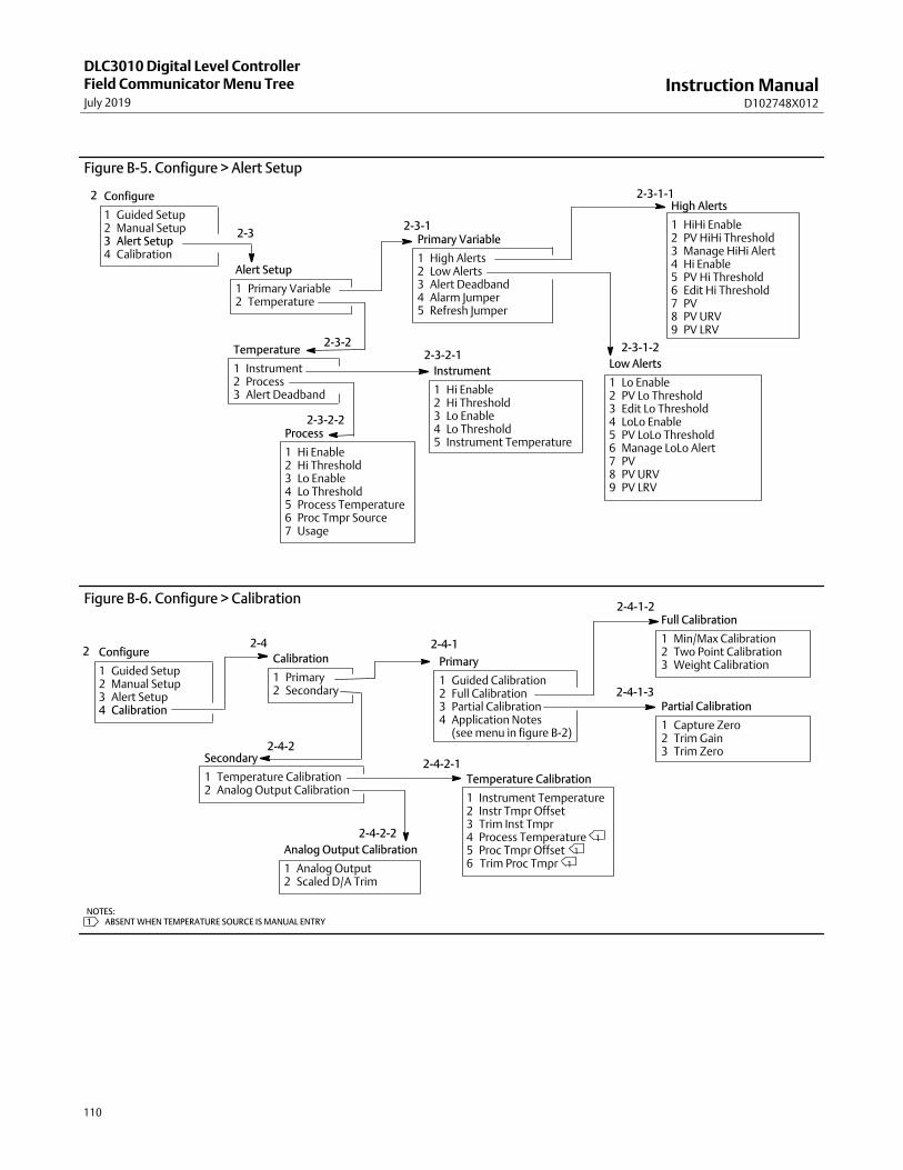
Instruction ManualD102748X012
DLC3010 Digital Level ControllerField Communicator Menu TreeJuly 2019
110
Figure B‐5. Configure > Alert Setup
Alert Setup
1 Primary Variable2 Temperature
2‐3-1Primary Variable
1 High Alerts2 Low Alerts3 Alert Deadband4 Alarm Jumper5 Refresh Jumper
Low Alerts
1 Lo Enable2 PV Lo Threshold3 Edit Lo Threshold4 LoLo Enable5 PV LoLo Threshold6 Manage LoLo Alert7 PV8 PV URV9 PV LRV
Temperature
1 Instrument2 Process3 Alert Deadband
Instrument
1 Hi Enable2 Hi Threshold3 Lo Enable4 Lo Threshold5 Instrument Temperature
2‐3-1-1
2‐3-22‐3-2-1
Configure
1 Guided Setup2 Manual Setup3 Alert Setup4 Calibration
2
2‐3
Process
1 Hi Enable2 Hi Threshold3 Lo Enable4 Lo Threshold5 Process Temperature6 Proc Tmpr Source7 Usage
High Alerts
1 HiHi Enable2 PV HiHi Threshold3 Manage HiHi Alert4 Hi Enable5 PV Hi Threshold6 Edit Hi Threshold7 PV8 PV URV9 PV LRV
2‐3-1-2
2‐3-2-2
2‐4-2
Primary
1 Guided Calibration2 Full Calibration3 Partial Calibration4 Application Notes 4 (see menu in figure B‐2)
Figure B‐6. Configure > Calibration
Calibration
1 Primary2 Secondary
Full Calibration
1 Min/Max Calibration2 Two Point Calibration3 Weight Calibration
Partial Calibration
1 Capture Zero2 Trim Gain3 Trim Zero
Secondary
1 Temperature Calibration2 Analog Output Calibration
Analog Output Calibration
1 Analog Output2 Scaled D/A Trim
Configure
1 Guided Setup2 Manual Setup3 Alert Setup4 Calibration
22‐4
Temperature Calibration
1 Instrument Temperature2 Instr Tmpr Offset3 Trim Inst Tmpr4 Process Temperature�1
5 Proc Tmpr Offset�1
62Trim Proc Tmpr�1
NOTES:1� ABSENT WHEN TEMPERATURE SOURCE IS MANUAL ENTRY
2‐4-1
2‐4-1-2
2‐4-1-3
2‐4-2-1
2‐4-2-2

Instruction ManualD102748X012
DLC3010 Digital Level ControllerField Communicator Menu Tree
July 2019
111
NOTES:1� IN LIQUID LEVEL MODE ONLY2� IN INTERFACE LEVEL MODE ONLY3� IN LIQUID DENSITY MODE ONLY4� ABSENT WHEN PROCESS TEMPERATURE SOURCE IS MANUAL ENTRY5� ABSENT IN LIQUID DENSITY MODE6� ABSENT IN LIQUID LEVEL MODE
� Service Tools
1 Alerts2 Variables3 Trends4 Maintenance
Alerts
1 No Active Alerts1 (Visible if there are no active alerts)
1 Refresh Alerts1 (Visible if an alert is active -- alert name plus description1 will be visible if the associated alert is active)
3-1
3-3
Maintenance
1 Tests2 Primary Calibration3 Secondary Calibration4 Reset/Restore
Tests
1 LCD Test2 Loop Test
Reset/Restore
1 Restore Factory Defaults2 Reset Device
Restore Factory Defaults
1 Restore Factory Configuration2 Restore Factory Compensation
3-4-1
3-4-4
3-4
3
Variables
1 Summary2 Liquid Level� 1
2 Interface Level� 2
2 Liquid Density� 3
3 Instrument Temperature4 Process Temperature5 Analog Output6 % Range
PV
1 Liquid Level� 1
1 Interface Level� 2
1 Liquid Density� 3
SV
1 Instrument Temperature
TV
1 Process Temperature
Primary Calibration
1 Full Calibration2 Partial Calibration
Full Calibration
1 Min/Max Calibration2 Two Point Calibration3 Weight Calibration
Partial Calibration
1 Capture Zero2 Trim Gain3 Trim Zero
Analog Output Calibration
1 Analog Output2 Scaled D/A Trim Temperature Calibration
1 Instrument Temperature2 Instr Tmpr Offset3 Trim Inst Tmpr4 Process Temperature� 4
5 Proc Tmpr Offset� 4
62Trim Proc Tmpr� 4
Trends
1 PV2 SV3 TV�4
Summary
1 Mapped Variables2 Compensation3 Signal Tracing4 Electronics Monitors
Mapped Variables
1 PV2 SV3 TV4 Analog Output5 % Range
Compensation
1 Comp. Torque Rate2 Upper Fluid Density� 2
3 Lower Fluid Density� 5
Signal Tracing
1 Constants2 Signals
Constants
1 Zero Ref Angle2 Driver Rod Length3 Mechanical Gain4 Displaser Weight5 Dry Deflection6 Displacer Volume7 Reference Buoyancy8 Displacer Length9 Level Offset
3-2
Signals
1 Sensor Rotation2 Rotation Change3 Buoyant Force4 Apparent SG� 3
5 Preliminary PV� 1
6 Scaled PV� 5
7 Final PV
Electronics Monitors
1 Input Circuit2 Processor3 Writes Remaining
Input Circuit
1 Hall Sensor Signal2 Hall Drive
Processor
1 Free Time Remaining
Writes Remaining
1 Configuration NVM2 Transducer NVM3 Buffer NVM
Secondary Calibration
1 Temperature Calibration2 Analog Output Calibration
Figure B‐7. Service Tools
3-2-1
3-2-1-1
3-2-1-2
3-2-1-3
3-2-1-3-1
3-2-1-3-2
3-2-1-4
3-2-1-4-1
3-2-1-4-23-2-1-4-3
3-4-3
3-4-3-23-4-
3-4-4-1
3-3-1
3-3-2
3-3-3
3-4-2
3-4-3-1
3-4-2-2
3-4-2-1
46
5
5
Instruction ManualD102748X012
DlC3010 Digital Level ControllerGlossaryJuly 2019
112
Glossary
Alert DeadbandThe amount by which a monitored variable mustreturn within normal limits for the alert to clear.
Alert ThresholdAn adjustable value that, when violated, activatesan alert.
AlgorithmA set of logical steps to solve a problem oraccomplish a task. A computer program containsone or more algorithms.
AlphanumericConsisting of letters and numbers.
ANSI (acronym)The acronym ANSI stands for the AmericanNational Standards Institute
BurstBurst mode is an extension to HART protocol thatprovides the continuous transmission of standardHART command response by a field device.
ByteA unit of binary digits (bits). A byte consists ofeight bits.
CommissioningFunctions performed with a Field Communicatorand the digital level controller to test theinstrument and loop and verify digital levelcontroller configuration data.
ConfigurationStored instructions and operating parameters fora FIELDVUE Instrument.
Control LoopAn arrangement of physical and electroniccomponents for process control. The electroniccomponents of the loop continuously measureone or more aspects of the process, then alterthose aspects as necessary to achieve a desiredprocess condition. A simple control loopmeasures only one variable. More sophisticatedcontrol loops measure many variables andmaintain specified relationships among thosevariables.
DampingOutput function that increases the time constantof the digital level controller output to smooththe output when there are rapid input variations.
DescriptorSixteen‐character field for additionalidentification of the digital level controller, itsuse, or location. The descriptor is stored in theinstrument and can be changed using a FieldCommunicator under the Device Identificationmenu.
Device IDUnique identifier embedded in the instrument atthe factory.
Device RevisionRevision number of the external interfacespecification that governs communicationbetween the Field Communicator and theinstrument.
Firmware RevisionThe revision number of the instrument firmware.Firmware is a program that is entered into theinstrument at time of manufacture and cannot bechanged by the user.
Free TimePercent of time that the microprocessor is idle. Atypical value is 25%. The actual value depends onthe number of functions in the instrument thatare enabled and on the amount ofcommunication currently in progress.
Instruction ManualD102748X012
DLC3010 Digital Level ControllerGlossary
July 2019
113
GainThe ratio of output change to input change.
Hardware RevisionRevision number of the Fisher instrumenthardware. The physical components of theinstrument are defined as the hardware.
HART (acronym)The acronym HART stands for HighwayAddressable Remote Transducer. Thecommunications standard that providessimultaneous analog and digital signaltransmission between control rooms and fielddevices.
HART TagSee Tag
HART Universal RevisionSee Universal Revision
Instrument Serial NumberThe serial number assigned to the instrument,which appears on the nameplate.
Lower Range Value (LRV)The value of the process variable that the digitallevel controller is currently configured to map tothe 4 mA endpoint in the 4 to 20 mA loop.
Lower Sensor Limit (LSL)Lowest value of the process variable that thedigital level controller can assign to a range value.Computation of an actual sensor limit for thisdevice would require a complex dynamicalgorithm dependent on much of theconfiguration data, process temperature, andother factors not currently available to thefirmware.
MemoryA type of semiconductor used for storingprograms or data. FIELDVUE instruments usethree types of memory: Random Access Memory(RAM), Read Only Memory (ROM), andNon‐Volatile Memory (NVM). See also theselistings in this glossary.
MenuA list of programs, commands, or other activitiesthat you select by using the arrow keys tohighlight the item then pressing ENTER, or byentering the numeric value of the menu item.
MessageThirty‐two character field for any additionalinformation the user may want to include.
MultidroppingThe connection of several field devices to a singlecommunications transmission line.
Non‐Volatile Memory (NVM)A type of semiconductor memory that retains itscontents even though power is disconnected.NVM contents can be changed duringconfiguration unlike ROM which can be changedonly at time of instrument manufacture. NVMstores configuration data.
On‐Line ConfigurationConfiguration of the digital level controlleroperational parameters using a FieldCommunicator connected to the instrument.
ParallelSimultaneous: said of data transmission on two ormore channels at the same time.
Polling AddressAddress of the instrument. If the digital levelcontroller is used in a point‐to‐pointconfiguration, set the polling address to 0. If it isused in a multidrop configuration, or split rangeapplication, set the polling address to a valuefrom 0 to 15.

Instruction ManualD102748X012
DlC3010 Digital Level ControllerGlossaryJuly 2019
114
Process Variable (PV)A physical quality or quantity which is monitoredas part of a control strategy. The digital levelcontroller can measure liquid level, interface levelbetween two liquids of different specific gravity,or liquid density.
ProtocolA set of data formats and transmission rules forcommunication between electronic devices.Devices that conform to the same protocol cancommunicate accurately.
Random Access Memory (RAM)A type of semiconductor memory that is normallyused by the microprocessor during normaloperation that permits rapid retrieval and storageof programs and data. See also Read OnlyMemory (ROM) and Non‐Volatile Memory (NVM).
Read‐Only Memory (ROM)A memory in which information is stored at thetime of instrument manufacture. You canexamine but not change ROM contents.
RerangingConfiguration function that changes the digitallevel controller 4 to 20 mA settings.
RTDThe abbreviation for resistance temperaturedetector. Temperature is measured by the RTD bycorrelating the resistance of the RTD elementwith temperature.
Send DataA Field Communicator command that transfersconfiguration data from the FieldCommunicator's working register to the digitallevel controller memory.
SI UnitsThe International System of Units. Includesmetric units such as ampere (A), meter (m),kilogram (kg), Kelvin (K), and second (s).
SoftwareMicroprocessor or computer programs androutines that reside in alterable memory (usuallyRAM), as opposed to firmware, which consists ofprograms and routines that are programmed intomemory (usually ROM) when the instrument ismanufactured. Software can be manipulatedduring normal operation, firmware cannot.
SpanAlgebraic difference between the upper andlower range values.
TagAn eight‐character field for identifying the digitallevel controller. The HART tag is stored in theinstrument and can be changed using a FieldCommunicator under the Device Identificationmenu.
Temperature SensorA device within the instrument that measures theinstrument's internal temperature.
Universal RevisionRevision number of the HART UniversalCommands which are the communicationsprotocol for the instrument.
Upper Range Value (URV)The value of the process variable that the digitallevel controller is currently configured to map tothe 20 mA endpoint in the 4 to 20 mA loop.
Upper Sensor Limit (USL)Highest value of the process variable that thedigital level controller can assign to a range value.Computation of an actual sensor limit for thisdevice would require a complex dynamicalgorithm dependent on much of theconfiguration data, process temperature, andother factors not currently available to thefirmware.
Working RegisterMemory location in a Field Communicator thattemporarily stores data as it is being entered.

Instruction ManualD102748X012
DLC3010 Digital Level ControllerIndex
July 2019
115
Index
Aaccess handle, 17
Access Handle Assembly, removing and replacing, 88
Active Alerts, Service Tools, 71
Advisory, Device Status, 31
Alarm Configuration, 34
Alarm Jumper, 27, 34, 56Changing Position, 28Locations, 27
alarm variables, default values, 38
Alert Setup, 51Primary Variable, 51
Alarm Jumper, 56Refresh Jumper, 56
Temperature, 56Instrument, 56Process , 57Temperature Deadband, 57
Altitude Rating, Operating Limits, 8
Ambient Temperature, Operative, 249, 11
Ambient Temperature and Humidity, OperatingLimits, 8
AMS Suite: Intelligent Device Manager, 3
Analog Output, 31Service Tools, Variables, 31, 74, 77
Analog Output Action, 32
Analog Output Calibration, 63, 78
Analog Output Fixed, Alert, 72
Analog Output Saturated, Alert, 71
Analog Output Signal, Digital Level Controller, 103
Apparent SG, 76
ATEX approved units, 24, 28
Available Configurations, 6
BBell 202 communication standard, 99
{BLANK], Diagnostic Message, 79
Buffer NVM, 72, 76
Buoyant Force, 76
Burst, 31
Burst Mode, 48
Burst Operation, 30
Burst Option, 49
Burst Variables, 30, 49
CCalibration, 31
Analog Output, 63, 78Full, 59Guided, 58Min/Max, 59, 66, 78Partial, 61
Capture Zero, 61, 78Trim Gain, 61, 78Trim Zero, 61, 78
Scaled D/A Trim, 63Temperature, 62, 78Theoretical, 60, 66Two Point, 59, 66, 67, 78Weight, 59, 66, 67, 78
Calibration , 58
Calibration / Ranging, 31
Calibration Examples, 63Density Applications - with Standard Displacer and
Torque Tube, 66Sensor Calibration at Process Conditions (Hot
Cut‐Over) when input cannot be varied, 67with an Overweight Displacer, 65with Standard Displacer and Torque Tube, 63
Capture Zero, Calibration, 61, 78
Change Action, 32, 43
Change Display Mode, 49
Change Protection, 34
Change PV, 43
Change Source, RTD Configuration, 44
Change Torque Rate, 41

Instruction ManualD102748X012
DLC3010 Digital Level ControllerIndexJuly 2019
116
Classifications/Certifications, 7CUTR, 7INMETRO, 7KGS, 7NEPSI, 7PESO CCOE, 7TIIS, 7
Cold Start, Alert, 72
Comm Status, 31Burst, 31Polled, 31
Communication Connections, 25
Communications, 48Burst Option, 49Scan Device, 49
Compensation, 74Compensation Torque Rate, 75Lower Fluid Density, 75Upper Fluid Density, 75
Compensation SpecificationDensity parameter, 7manual, 7Transducer, 7
Configuration, digital level controller, 15
Configuration Advice, 36
configuration data, factory, 35
Configuration NVM, 76
Connection Styles, Caged Sensor, 11
ConnectionsCommunication, 25current loop, 22Electrical, 22Power/Current Loop, 25RTD, 25Test, 26
Construction Materials, 8249 Sensors, 11
Coupling, 39protecting, 15
CUTR (Customs Union Technical Regulations), Russia,Kazakhstan, Belarus, and Armenia, 7
DD/A Trim, 58
Damping, 42
Date, 33, 48
DD Information, 33
Dead Band, 6
Decimal Places, 50
Density, Process, Operating influences, 6
density applications, 39
Description, 33, 48
Device ID, 33
Device Identification, 48Date, 48Description, 48Final Assembly Number, 48Message, 48Sensor Serial Number, 48Tag, 48
Device Information, 33Alarm Configuration, 34Alarm Type and Security, 34Change Protection, 34DD Information, 33Device Revision, 33Firmware Revision, 33Hardware Revision, 33Identification, 33
Date, 33Description, 33Message, 33Model, 33Serial Numers, 33Tag, 33
Refresh Jumper, 34Revisions, 33Security, 34Signal Levels, 34Universal Revision, 33Write Protect, 34
Device Revision, 33
Device Status, 31Advisory, 31Failed, 31Good, 31Maintenance, 31
Diagnostic Messages, LCD Meter, 79
Diagnostics, Hardware, 80
Digital Monitors, Specifications, 7
digital‐to‐analog (D/A) output, 100
Instruction ManualD102748X012
DLC3010 Digital Level ControllerIndex
July 2019
117
DisplacerLength, 40Volume, 40Weight, 40
Displacer Data, Weight, 40
Displacer Length, 58, 75
Displacer Lengths, Sensor, 11
Displacer SensorsCaged, 12Cageless, 12
displacer serial number, 33, 48
Displacer Volume, 58, 75
Displacer Weight, 75
Display Mode, 49
Distributor, 33
Driver Rod Length, 40, 58, 75
Dry Deflection, 75
EEducational Services, 5
EEPROM, 102
Electrical Classification, 7Hazardous Area
ATEX, 7CSA, 7FM, 7IECEx, 7
Electrical Connections, 8, 22
Electrical Housing, 7
Electromagnetic Compatibility, 7
electromagnetic interference (EMI) protection, 103
Electronic MonitorsInput Circuit, 76Processor, 76Writes Remaining, 76
electronics, encapsulated, 27
Electronics ModuleMaintenance, 86Removing, 86Replacing, 86
Electronics Monitors, 76Service Tools, Variables, 76
EMI filters, 102
EN 61326‐1:2013, Electromagnetic Compatibility, 7
EN 61326‐2‐3:2006, Electromagnetic Compatibility, 7
Enter Constant Density, 46
Equalizing Connections, 13
FFAIL HDWR, Diagnostic Message, 80
Failed, Device Status, 31
Fast-Key Sequence, 105
Field Communicator Menu Tree, 105
Field Wiring, 23
Final Assembly Number, 33, 48
Final PV, 76
Firmware Revision, 33
Flexures, protecting, 15
Fluid(s), 45
Foxboro‐Eckardt Sensors, Mounting Parts, 97
Free Time Remaining, 76
Full Calibration, 59
GGood, Device Status, 31
ground strap, 24
Grounding, 24Shielded Wire, 24
Guided Calibration, 58
Guided Setup, 36
HHall sensor, 102
Hall Sensor Drive, 76
Hall Sensor Signal, 76
Hardware Diagnostics, 80
Hardware Revision, 33
HART Communication, 7Principle of Operation, 99
HART protocol, 99
HART tag, 33, 48
HART Tri‐Loop, 29
Hazardous Area Classifications, 17

Instruction ManualD102748X012
DLC3010 Digital Level ControllerIndexJuly 2019
118
Heat Insulator, Installation, 20
Heat Insulator Assembly, Guidelines for Use, 21
High Alerts, 51
High Temperature Applications, Mounting, 20
Hysteresis, 6
Hysteresis plus Deadband, 6
I
Immunity Performance, 8
Independent Linearity, 6
Initial Setup, 35
INMETRO, National Institute of Metrology,Standardization, and Industrial Quality (Brazil), 7
Inner Guide and Access Handle Assembly, Removingand Replacing, 88
Input Signal249, 11DLC3010, 6
Installation, 15249 Sensor, 17DLC3010 on 249 Sensor, 20
High Temperature Applications, 20, 21Electrical, 22Field Wiring, 23Heat Insulator, 20Multichannel, 26Power/Current Loop Connections, 25RTD Connections, 25
Installation Flowchart, 16HART Tri‐Loop, 29
Instrument Display, 49Change Display Mode, 49
% Range, 50PV, 49PV/% Range, 50PV/Process Temperature, 49
Decimal Places, 50Display Mode, 49LCD Configuration, 49
Instrument Mounting, 41
Instrument Serial Number, 33, 48
Instrument Setup, 36
Instrument TemperatureAlert Setup, 56Service Tools, Variables, 76
Instrument Temperature Offset, 58
Instrument Temperature Too High, Alert, 72
Instrument Temperature Too Low, Alert, 72
Interface Applications, 38, 39Density Variations in, 69
Interface Level, 31
intrinsic safety, and multidrop installations, 99
intrinsically safe applications, 23
KKGS, Korea Gas Safety Corporation (South Korea), 7
LLCD Configuration, 49
LCD meter, 19, 100Diagnostic Messages, 79
[BLANK], 79FAIL HDWR, 80OFLOW, 80
removing, 85Replacing, 85
LCD Meter Assembly, Maintenance, 84
LCD Meter Indications, 7
LCD Test, Maintenance, 77
Length Units, Sensor, 40
Level Offset, 32, 43, 58
Level Signature Series Test, 8
Lever AssemblyRemoving, 89Replacing, 90
Lever Lock, 15
lift-off voltage, 22
Liquid Density, 31
Liquid Level, 31
Load Steam Tables, process fluid, 47
loop connection terminals, 102
loop interface, 100
Loop Test, 28Maintenance, 77
Low Alerts, 54
Instruction ManualD102748X012
DLC3010 Digital Level ControllerIndex
July 2019
119
Lower Fluid Density, 45Service Tools, Variables, 75
Lower Range Value, 32, 43
Lower Sensor Limit, 32, 43
LRV (Lower Range Value), 58
MMaintenance
Device Status, 31Electronics Module
removing, 86replacing, 86
Inner Guide and Access Handle Assembly, removingand replacing, 88
LCD Meter Assembly, 84removing, 85replacing, 85
Lever Assembly, 89removing, 89replacing, 90
Primary Calibration, 77removing the DLC3010 from a 249 sensor
high temperature application, 84standard temperature application, 83
Reset/Restore, 78Service Tools, 77Terminal Box, 87
removing, 87replacing, 87
Tests, 77LCD, 77Loop, 77
Maintenance & Troubleshooting, 79
Maitenance , Electronics Module, 86
Manual Setup, 40
Mapped Variables, 73
Masoneilan Sensors, Mounting Parts, 95
Materials249, 11
Process Temperature, 11Displacer and Torque Tube, 11
Measure Density, 69
Measure SG, 46
Mechanical Gain, 75excessive, 68
Menu Tree, Field Communicator, 105
Message, 33, 48
microprocessor, 100
Min/Max Calibration, 59, 66, 78
Minimum Differential Specific Gravity, 7, 8
Minimum Span, 32, 43
Model, 33
modems, Bell 202, 99
moment arm, 36
Moment Arm (Driver Rod) Length, 37
Mounting, 41249 Sensor, 17Digital Level Controller Orientation, 18DLC3010, 17
On 249 Sensor, 20DLC3010 On 249 Sensor, High Temperature
Applications, 20, 21Typical Caged Sensor (249), 18Typical Cageless Sensor (249), 18
Mounting Kits, 91
Mounting Parts, 95
Mounting Positions, 8249 Series, 11typical, DLC3010 on 249 sensor, 19
Multichannel Installations, 26
Multidrop Communicationactivating, 100Principle of Operation, 99
Multidrop installations, intrinsic safety, 99
NNAMUR NE 43, 52, 54, 103
NEPSI, National Supervision and Inspection Centre forExplosion Protection and Safety ofInstrumentation (China), 7
Non‐Primary Variable Out of Limits, Alert, 71
NVM (non-volatile memory), 62
NVM Write Limit Exceeded, Alert, 72
OOFLOW, Diagnostic Message, 80
Operating Limits, 8Altitude Rating, 8Ambient Temperature and Humidity, 8Process Temperature, 8Weight, 8
Output Signal, DLC3010, 6

Instruction ManualD102748X012
DLC3010 Digital Level ControllerIndexJuly 2019
120
Overview, 31Device Information, Identification, Device ID, 33Process Temperature, 31
P
Partial Calibration, 61
Parts, 91, 92 List, 92
DLC3010, 92Terminal Box Assembly, 94Terminal Box Cover, 94Transducer Assembly, 93
Kits, 91Mounting, 95Ordering, 91
Percent (%) Range, 50Service Tools, Variables, 74, 77
PESO CCOE, Petroleum and Explosives SafetyOrganisation - Chief Controller of Explosives(India), 7
Polled, 31
polling address, 27, 48, 100
Power Supply, Load Limits, 22
Power Supply Effect, Operating influences, 6
Power/Current Loop Connections, 25
Preliminary PV is, 76
Pressure Boundary Materials, allowable processtemperatures, 249 Sensors, 11
Primary Calibration, Maintenance, 77
Primary Variable, 42Alert Setup, 51
High Alerts, 51Low Alerts, 54PV Deadband, 56
Principle of OperationDLC3010, 100HART Communication, 99Multidrop Communication, 99
Proc Temp Offset, 58
Process Conditions, 44Change Source, RTD, 44Enter Constant SG, 46Fluid(s), 45Load Steam Tables, 47Lower Fluid Density, 45Measure SG, 46Process Temperature Source, 44RTD Data, 44Upper Fluid Density, 45View/Edit SG Tables, 45, 47
Process Density, Operating influences, 6
Process Temperature, 31, 44, 57Alert Setup, 57Operating Limits, 8Service Tools, Variables, 76
Process Temperature Signal Failed, Alert, 71
Process Temperature Source, 44
Process Temperature Too High, Alert, 72
Process Temperature Too Low, Alert, 72
Process Temperatures, extreme, 70
Processor Free Time Depleted, Alert, 72
processor module, 100
Proportional Band, effect of, 69
Protection, 36, 40
PV, 49Service Tools, Variables, 73
PV alert deadband, 39
PV alert thresholds, 39
PV Deadband, 51, 56
PV Hi Alert, 73
PV HiHi Alert, 73
PV Lo Alert, 73
PV LoLo Alert, 73
PV Out of Limits, Alert, 73
PV/% Range, 50
PV/Process Temperature, 49
RRanging, 32, 43
Change Action, 43Level Offset, 43Lower Range Value, 43Lower Sensor Limit, 43Minimum Span, 43Set Level Offset, 43Upper Range Value, 43Upper Sensor Limit, 43
Reference Buoyancy, 75
Instruction ManualD102748X012
DLC3010 Digital Level ControllerIndex
July 2019
121
Refresh Jumper, 34, 56
Related Documents, 5
remote indicator, 8
Repeatability, 6
replacement parts, 91
Reset Device, 78
Reset/Restore, Maintenance, 78
Restore Factory Compensation, 78
Restore Factory Configuration, 78
Restore Factory Defaults , 78
returned goods information, 90
reverse polarity protection, 103
Revisions, 33
Rosemount 333 HART Tri‐Loop HART‐to‐Analog SignalConverter, 29
Rotation Change, 76
RTD, Setup, 45
RTD Connections, 25Three‐Wire, 25Two‐Wire, 25
RTD Data, 44
RTD Wire Resistance, 44
SSaturated Water, Specific Gravity vs Temperature
Table, example, 45
Scaled D/A Trim, Analog Output Calibration, 63
Scaled PV, 76
Scan Device, 49
Secondary Variable, 42
Security, 34
Sensor, Serial Number, 33
Sensor Connection Compartment, 18
Sensor Damping, 41
Sensor Dimensions, 40Displacer Length, 40Displacer Volume, 40Displacer Weight, 40Driver Rod Length, 40
Sensor Drive Failed, Alert, 71
Sensor information, 35
Sensor Nameplate, example, 37
Sensor Rotation, 75
Sensor Serial Number, 48
Sensor Signal Failed, Alert, 71
Sensor Units, 40Length, 40Temperature, 40Torque Rate, 40Volume, 40Weight, 40
Serial NumberInstrument, 33, 48Sensor, 33, 48
Serial Numbers, 33
Service Tools, 71Active Alerts, 71Maintenance, 77Trends, 77Variables, 73
Compensation, 74Mapped Variables, 73
Set Level Offset, 32, 43
SetupGuided, 36Manual, 40
SG, 58
SG Tables, View/Edit, 45, 47
shaft extension, torque tube, 20
signal conditioning, 100
Signal Levels, 34
Signal Tracing, 75Constants, 75Signals, 75Service Tools, Variables, 75
Special Instructions for “Safe Use” and Installations inHazardous Locations, 17
specific gravity tables, 45
Specific Gravity vs Temperature Table for SaturatedSteam, example, 47
Specifications, 4249 Sensors, 11
Supply Requirements, 7
SV, Service Tools, Variables, 73
Instruction ManualD102748X012
DLC3010 Digital Level ControllerIndexJuly 2019
122
TTag, 33, 48
Temperature, Alert Setup, 56
Temperature Calibration, 62, 78
Temperature Compensation, 70
Temperature Deadband, 56, 57
temperature sensor, 102
Temperature Units, Sensor, 40
Temperature, Ambient, Operating influences,DLC3010, 6
Temperature, Process, Operating influences, 6
terminal board, 100
Terminal Box, 24Cover Assembly, Parts, 94Maintenance, 87Removing, 87Replacing, 87
Terminal Box Assembly, Parts, 94
terminal box cover set screw, ATEX approved unit, 24
Test connections, 26
Test Terminals, 26, 82
Tests, Maintenance, 77
Theoretical Reversible Temperature Effect onCommon Torque Tube Materials
Degrees Celsius, 9Degrees Fahrenheit, 10
Theoretical Torque Tube (TT) Rates, 68
Third Variable, 42
TIIS, Technology Institution of Industrial Safety (Japan),7
Tools, required for maintenance, 82
Torque Rate, 41
Torque Rate Units, Sensor, 40
Torque Tube, 41 Rate, 41Change Torque Rate, torque tube, 41Changing Material, 41Edit Compensation, 41
Torque Tube (TT) Rates, Theoretical, 68
Torque Tube Rate, 58
torque tube shaft extension, 20
Transducer Assembly, Parts, 93
transducer board, 100, 102
Transducer NVM, 76
transient power surge protection, 103
Transient Voltage Protection, Operating influences, 6
Trends, Service Tools, 77
333 HART Tri-Loop, 29
Tri-Loop, 29Commissioning DLC3010 for use with, 30Configuring DLC3010 for use with, 29
Trim Gain, Calibration, 61, 78
Trim Zero, Calibration, 61, 78
Troubleshooting, 79, 81, 82
TT Material, 41
Turn Cells Off, 77
TV, Service Tools, Variables, 74
Two Point Calibration, 59, 66, 67, 78
UUnits, changing variable, 42
Universal Revision, 33
Upper Fluid Density, 45Service Tools, Variables, 75
Upper Range Value, 32, 43
Upper Sensor Limit, 32, 43
URV (Upper Range Value), 58
VVariables, 42
alarm, default values, 38Burst, 30, 49Change PV, 43Damping, 42Service Tools, 73Units, 42
View/Edit SG Tables, 45, 47
voltage, lift-off, 22
Volume Units, Sensor, 40
Instruction ManualD102748X012
DLC3010 Digital Level ControllerIndex
July 2019
123
WWeight, Operating Limits, 8
Weight Calibration, 59, 66, 67, 78
Weight Units, Sensor, 40
Wiring, Field, 23
Working Pressures, Sensor, 11
Write Protect, 34, 36See also Protection
Writes RemainingBuffer NVM, 76Configuration NVM, 76Transducer NVM, 76
Y
Yamatake NQP Sensor, Mounting Parts, 97
Z
zero buoyancy, 39
Zero Reference Angle, 58, 75

Instruction ManualD102748X012
DLC3010 Digital Level ControllerJuly 2019
124
Emerson Automation Solutions Marshalltown, Iowa 50158 USASorocaba, 18087 BrazilCernay, 68700 FranceDubai, United Arab EmiratesSingapore 128461 Singapore
www.Fisher.com
The contents of this publication are presented for informational purposes only, and while every effort has been made to ensure their accuracy, they are notto be construed as warranties or guarantees, express or implied, regarding the products or services described herein or their use or applicability. All sales aregoverned by our terms and conditions, which are available upon request. We reserve the right to modify or improve the designs or specifications of suchproducts at any time without notice.
� 2000, 2019 Fisher Controls International LLC. All rights reserved.
Fisher, FIELDVUE, DeltaV, and Tri‐Loop are marks owned by one of the companies in the Emerson Automation Solutions business unit of Emerson ElectricCo. Emerson Automation Solutions, Emerson, and the Emerson logo are trademarks and service marks of Emerson Electric Co. HART is a registeredtrademark of the FieldComm Group. All other marks are the property of their respective owners.
Neither Emerson, Emerson Automation Solutions, nor any of their affiliated entities assumes responsibility for the selection, use or maintenanceof any product. Responsibility for proper selection, use, and maintenance of any product remains solely with the purchaser and end user.