fisher controller device setup and accessing ...... fisher fieldvue dvc6200p digital valve...
TRANSCRIPT
www.Fisher.com
Fisher™ FIELDVUE™ DVC6200p Digital ValveController Device Setup and AccessingCommunication and Calibration using SiemensSIMATIC Manager/PDM
ContentsRelated Documents 2. . . . . . . . . . . . . . . . . . . . . . . . . . .Connecting the Digital Valve Controller usingEnhanced Device Description (EDD) for SiemensSIMATIC PDM 3. . . . . . . . . . . . . . . . . . . . . . . . . . . . . . . .
Setting PG/PC Interface 4. . . . . . . . . . . . . . . . . . . . . . .Loading the DVC6200p EDD to the SIMATIC
Manager/PDM Catalog 8. . . . . . . . . . . . . . . . . . . . .Device Setup using Siemens PDM Software 11. . . . .
Going Online with the DVC6200p 17. . . . . . . . . . . . . .Performing One-Step Local Quick Setup
to Calibrate and Tune the DVC6200p 19. . . . . . . .
This document takes you through setting up and accessing the DVC6200p using Siemens SIMATIC PDM software, aswell as performing initial actuator and valve configuration, calibration, and tuning using the Guided Setup procedure.
The procedures covered in this supplement were completed using Siemens SIMATIC Manager/PDM 8.1. While thesteps taken should remain basically the same, screens may vary slightly if you are using a different version of thesoftware.
Ensure that all necessary files, including the latest DVC6200p EDD, are available.
Note
Setting PG/PC Interface and loading the DVC6200p EDD are generally required only once per computer.
Refer to the DVC6200 Series Quick Start Guide (D103556X012) for DVC6200pinstallation, connection and initial configuration information. If a copy of thisquick start guide is needed scan or click the QR code at the right, contact yourEmerson sales office sales office or Local Business Partner, or visit our websiteat www.Fisher.com.
Instruction Manual SupplementD103560X012
DVC6200p Digital Valve ControllerNovember 2017
Scan or click to access field support
Instruction Manual SupplementD103560X012
DVC6200p Digital Valve ControllerNovember 2017
2
Related Documents� DVC6200 Series Digital Valve Controller quick start guide (D103556X012)
� DVC6200p Digital Valve Controller instruction manual (D103563X012)
All documents are available from your Emerson sales office or Local Business Partner. Also visit our website atwww.Fisher.com.
Instruction Manual SupplementD103560X012
DVC6200p Digital Valve ControllerNovember 2017
3
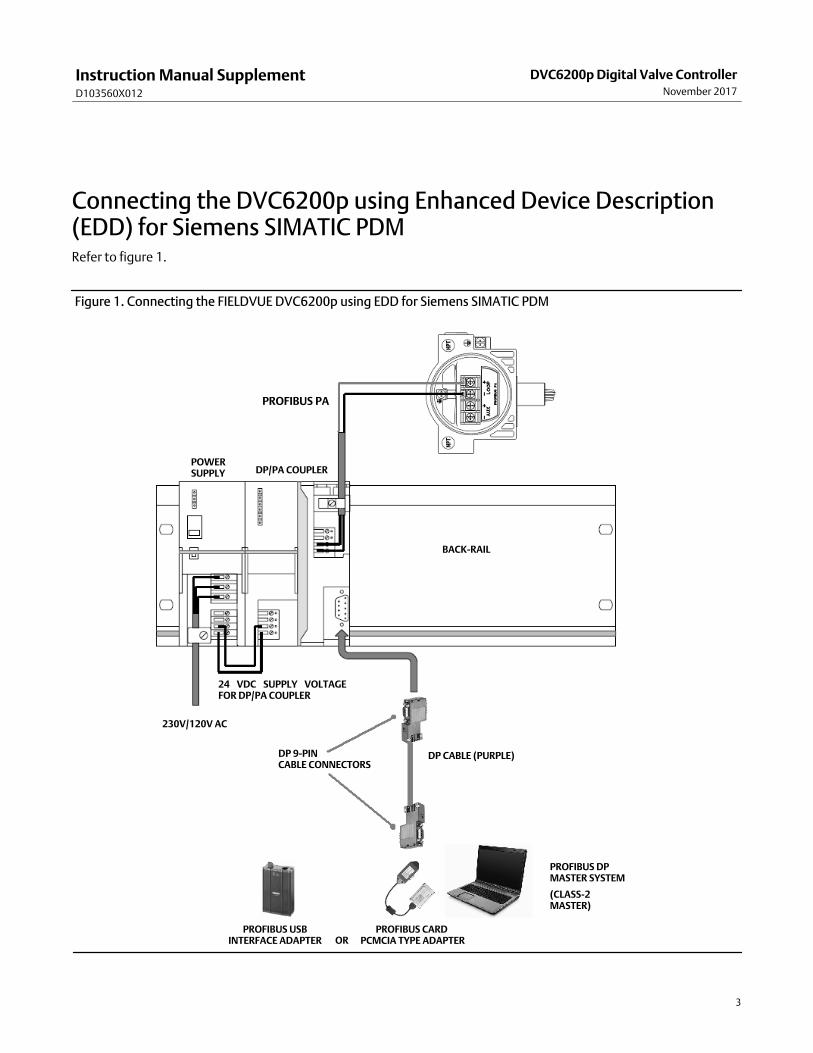
Connecting the DVC6200p using Enhanced Device Description(EDD) for Siemens SIMATIC PDMRefer to figure 1.
Figure 1. Connecting the FIELDVUE DVC6200p using EDD for Siemens SIMATIC PDM
BACK-RAIL
PROFIBUS PA
POWERSUPPLY DP/PA COUPLER
24 VDC SUPPLY VOLTAGEFOR DP/PA COUPLER
230V/120V AC
DP 9-PINCABLE CONNECTORS
DP CABLE (PURPLE)
PROFIBUS USBINTERFACE ADAPTER
PROFIBUS DPMASTER SYSTEM
(CLASS-2MASTER)
ORPROFIBUS CARD
PCMCIA TYPE ADAPTER
Instruction Manual SupplementD103560X012
DVC6200p Digital Valve ControllerNovember 2017
4
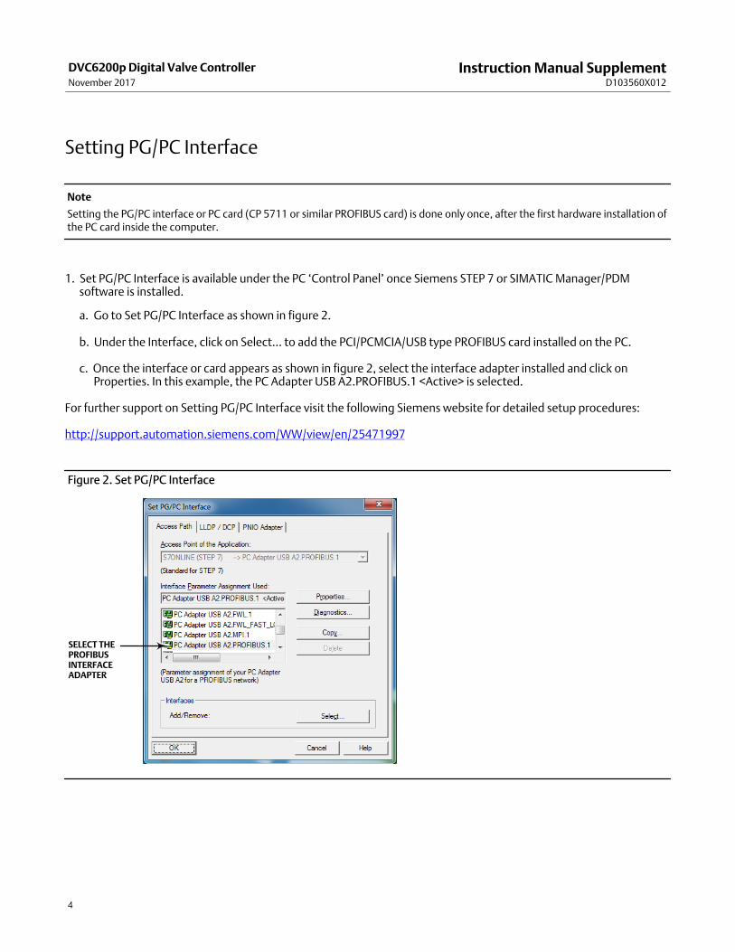
Setting PG/PC Interface
Note
Setting the PG/PC interface or PC card (CP 5711 or similar PROFIBUS card) is done only once, after the first hardware installation ofthe PC card inside the computer.
1. Set PG/PC Interface is available under the PC ‘Control Panel’ once Siemens STEP 7 or SIMATIC Manager/PDMsoftware is installed.
a. Go to Set PG/PC Interface as shown in figure 2.
b. Under the Interface, click on Select... to add the PCI/PCMCIA/USB type PROFIBUS card installed on the PC.
c. Once the interface or card appears as shown in figure 2, select the interface adapter installed and click onProperties. In this example, the PC Adapter USB A2.PROFIBUS.1 <Active> is selected.
For further support on Setting PG/PC Interface visit the following Siemens website for detailed setup procedures:
http://support.automation.siemens.com/WW/view/en/25471997
Figure 2. Set PG/PC Interface
SELECT THEPROFIBUSINTERFACEADAPTER
Instruction Manual SupplementD103560X012
DVC6200p Digital Valve ControllerNovember 2017
5
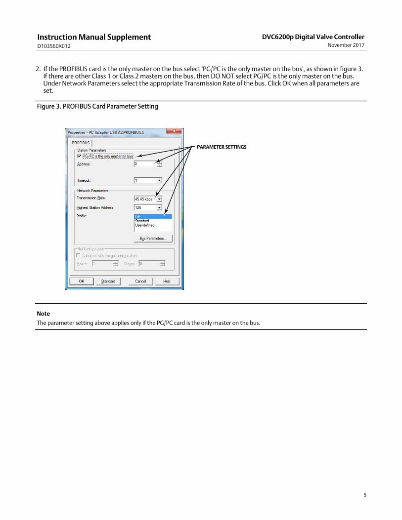
2. If the PROFIBUS card is the only master on the bus select 'PG/PC is the only master on the bus', as shown in figure 3.If there are other Class 1 or Class 2 masters on the bus, then DO NOT select PG/PC is the only master on the bus.Under Network Parameters select the appropriate Transmission Rate of the bus. Click OK when all parameters areset.
Figure 3. PROFIBUS Card Parameter Setting
PARAMETER SETTINGS
Note
The parameter setting above applies only if the PG/PC card is the only master on the bus.
Instruction Manual SupplementD103560X012
DVC6200p Digital Valve ControllerNovember 2017
6
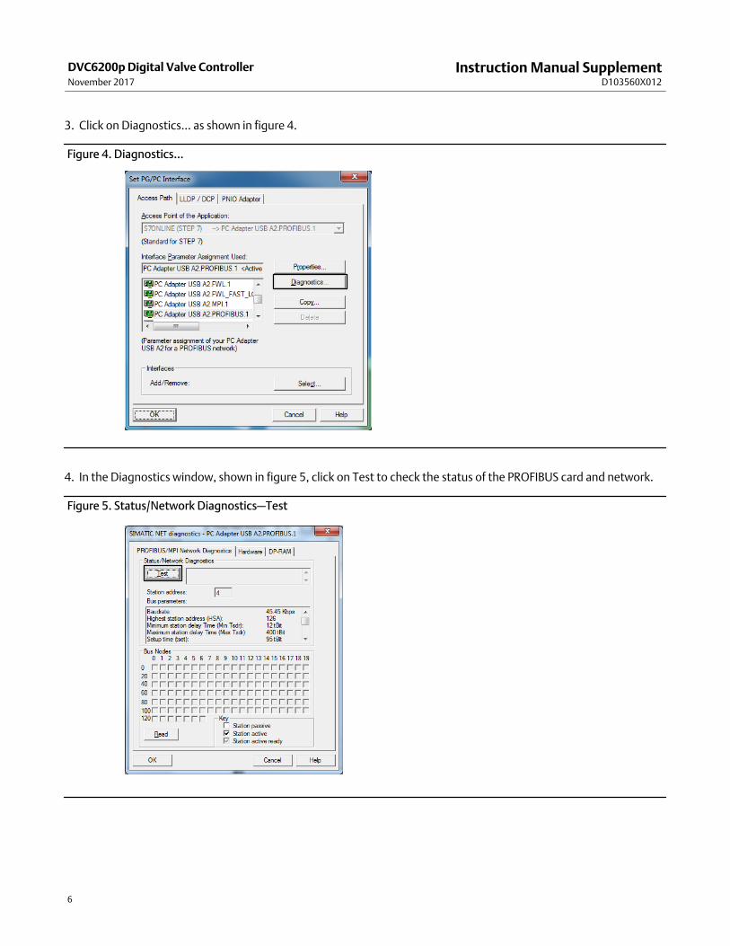
3. Click on Diagnostics... as shown in figure 4.
Figure 4. Diagnostics...
4. In the Diagnostics window, shown in figure 5, click on Test to check the status of the PROFIBUS card and network.
Figure 5. Status/Network Diagnostics—Test
Instruction Manual SupplementD103560X012
DVC6200p Digital Valve ControllerNovember 2017
7
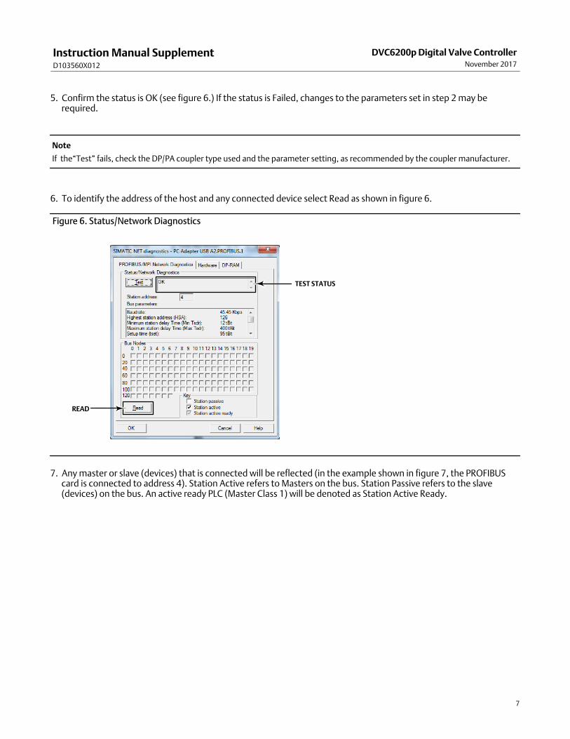
5. Confirm the status is OK (see figure 6.) If the status is Failed, changes to the parameters set in step 2 may berequired.
Note
If the“Test” fails, check the DP/PA coupler type used and the parameter setting, as recommended by the coupler manufacturer.
6. To identify the address of the host and any connected device select Read as shown in figure 6.
Figure 6. Status/Network Diagnostics
TEST STATUS
READ
7. Any master or slave (devices) that is connected will be reflected (in the example shown in figure 7, the PROFIBUScard is connected to address 4). Station Active refers to Masters on the bus. Station Passive refers to the slave(devices) on the bus. An active ready PLC (Master Class 1) will be denoted as Station Active Ready.
Instruction Manual SupplementD103560X012
DVC6200p Digital Valve ControllerNovember 2017
8
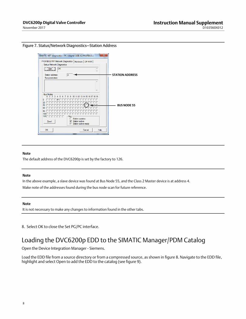
Figure 7. Status/Network Diagnostics—Station Address
STATION ADDRESS
BUS NODE 55
Note
The default address of the DVC6200p is set by the factory to 126.
Note
In the above example, a slave device was found at Bus Node 55, and the Class 2 Master device is at address 4.
Make note of the addresses found during the bus node scan for future reference.
Note
It is not necessary to make any changes to information found in the other tabs.
8. Select OK to close the Set PG/PC interface.
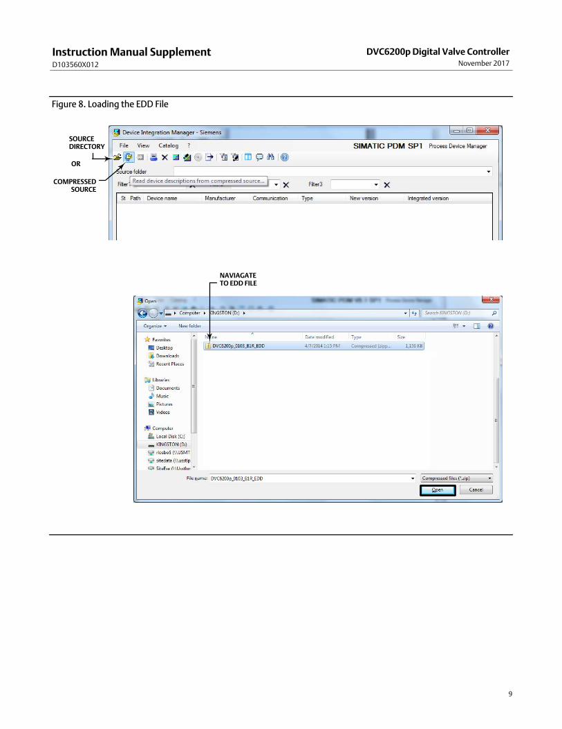
Loading the DVC6200p EDD to the SIMATIC Manager/PDM CatalogOpen the Device Integration Manager - Siemens.
Load the EDD file from a source directory or from a compressed source, as shown in figure 8. Navigate to the EDD file,highlight and select Open to add the EDD to the catalog (see figure 9).
Instruction Manual SupplementD103560X012
DVC6200p Digital Valve ControllerNovember 2017
9
Figure 8. Loading the EDD File
SOURCEDIRECTORY
COMPRESSEDSOURCE
OR
NAVIAGATE TO EDD FILE
Instruction Manual SupplementD103560X012
DVC6200p Digital Valve ControllerNovember 2017
10
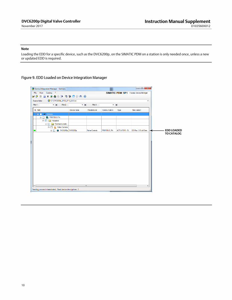
Note
Loading the EDD for a specific device, such as the DVC6200p, on the SIMATIC PDM on a station is only needed once, unless a newor updated EDD is required.
Figure 9. EDD Loaded on Device Integration Manager
EDD LOADED TO CATALOG
Instruction Manual SupplementD103560X012
DVC6200p Digital Valve ControllerNovember 2017
11
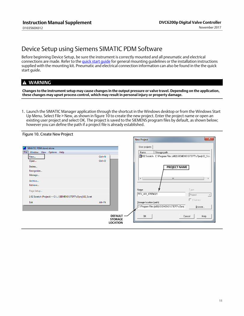
Device Setup using Siemens SIMATIC PDM SoftwareBefore beginning Device Setup, be sure the instrument is correctly mounted and all pneumatic and electricalconnections are made. Refer to the quick start guide for general mounting guidelines or the installation instructionssupplied with the mounting kit. Pneumatic and electrical connection information can also be found in the the quickstart guide.
WARNING
Changes to the instrument setup may cause changes in the output pressure or valve travel. Depending on the application,these changes may upset process control, which may result in personal injury or property damage.
1. Launch the SIMATIC Manager application through the shortcut in the Windows desktop or from the Windows StartUp Menu. Select File > New, as shown in figure 10 to create the new project. Enter the project name or open anexisting user project and select OK. The project is saved to the SIEMENS program files by default, as shown below;however you can define the path if a project file is already established.
Figure 10. Create New Project
DEFAULTSTORAGE
LOCATION
PROJECT NAME
Instruction Manual SupplementD103560X012
DVC6200p Digital Valve ControllerNovember 2017
12
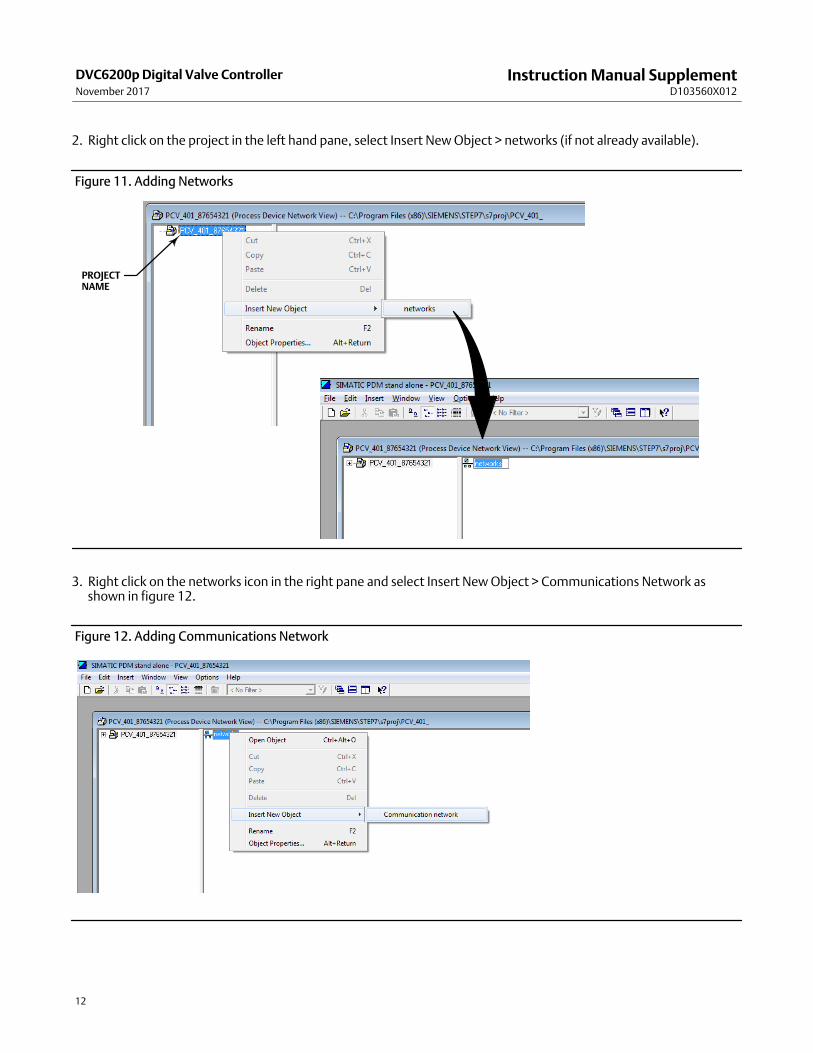
2. Right click on the project in the left hand pane, select Insert New Object > networks (if not already available).
Figure 11. Adding Networks
PROJECTNAME
3. Right click on the networks icon in the right pane and select Insert New Object > Communications Network asshown in figure 12.
Figure 12. Adding Communications Network

Instruction Manual SupplementD103560X012
DVC6200p Digital Valve ControllerNovember 2017
13
4. Enter the Object name then click on Assign Device Type as shown below. Navigate to PROFIBUS DP network andselect OK.
Figure 13. Assign Device Type
Instruction Manual SupplementD103560X012
DVC6200p Digital Valve ControllerNovember 2017
14
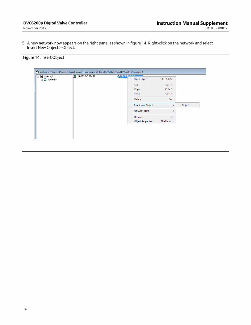
5. A new network now appears on the right pane, as shown in figure 14. Right-click on the network and select Insert New Object > Object.
Figure 14. Insert Object
Instruction Manual SupplementD103560X012
DVC6200p Digital Valve ControllerNovember 2017
15
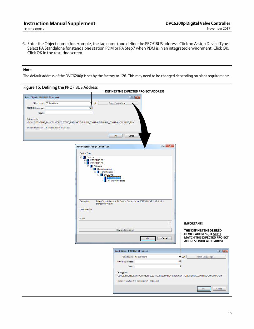
6. Enter the Object name (for example, the tag name) and define the PROFIBUS address. Click on Assign Device Type.Select PA Standalone for standalone station PDM or PA Step7 when PDM is in an integrated environment. Click OK.Click OK in the resulting screen.
Note
The default address of the DVC6200p is set by the factory to 126. This may need to be changed depending on plant requirements.
Figure 15. Defining the PROFIBUS AddressDEFINES THE EXPECTED PROJECT ADDRESS
IMPORTANT!!
THIS DEFINES THE DESIRED DEVICE ADDRESS, IT MUSTMATCH THE EXPECTED PROJECTADDRESS INDICATED ABOVE
Instruction Manual SupplementD103560X012
DVC6200p Digital Valve ControllerNovember 2017
16
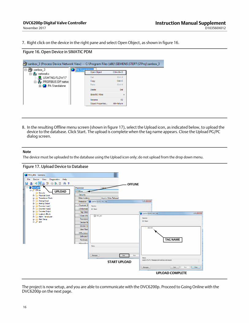
7. Right click on the device in the right pane and select Open Object, as shown in figure 16.
Figure 16. Open Device in SIMATIC PDM
8. In the resulting Offline menu screen (shown in figure 17), select the Upload icon, as indicated below, to upload thedevice to the database. Click Start. The upload is complete when the tag name appears. Close the Upload PG/PCdialog screen.
Note
The device must be uploaded to the database using the Upload icon only; do not upload from the drop down menu.
Figure 17. Upload Device to Database
UPLOAD
START UPLOAD
TAG NAME
UPLOAD COMPLETE
OFFLINE
The project is now setup, and you are able to communicate with the DVC6200p. Proceed to Going Online with theDVC6200p on the next page.
Instruction Manual SupplementD103560X012
DVC6200p Digital Valve ControllerNovember 2017
17
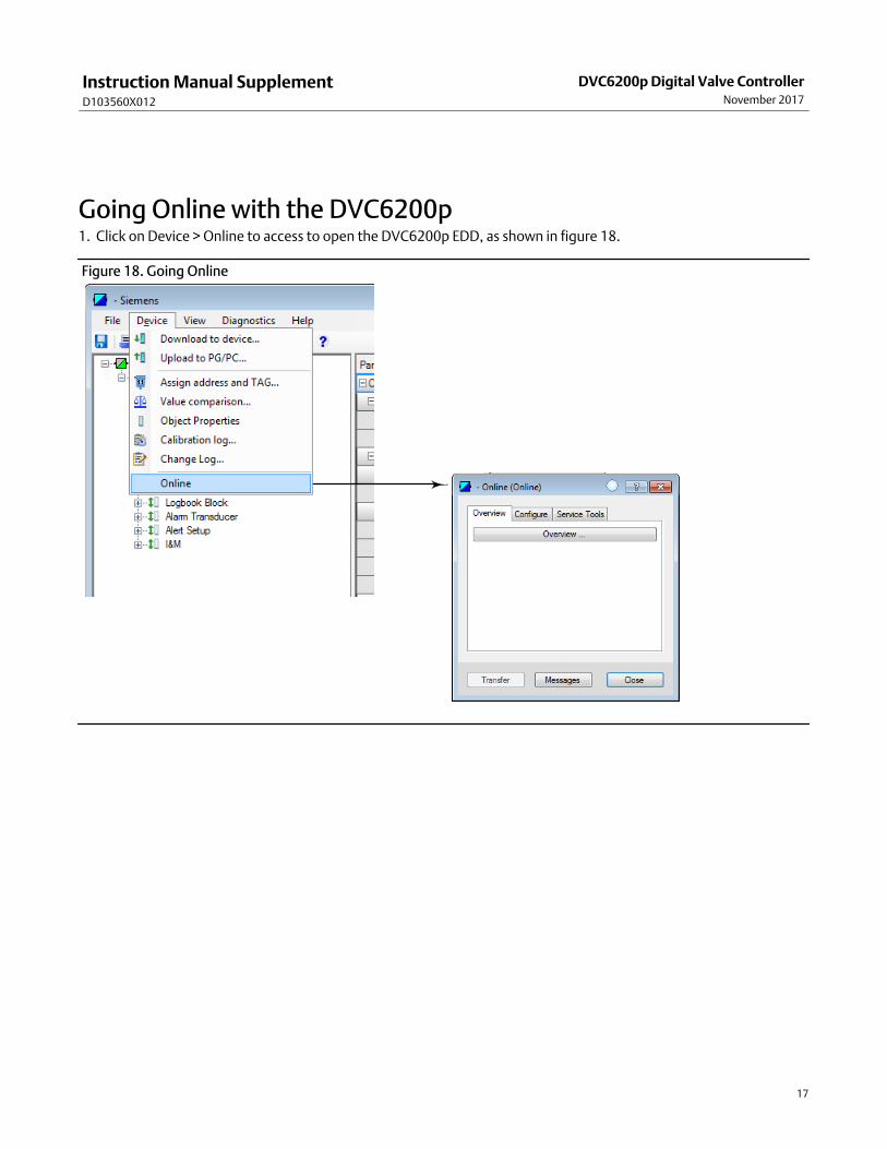
Going Online with the DVC6200p1. Click on Device > Online to access to open the DVC6200p EDD, as shown in figure 18.
Figure 18. Going Online
Instruction Manual SupplementD103560X012
DVC6200p Digital Valve ControllerNovember 2017
18
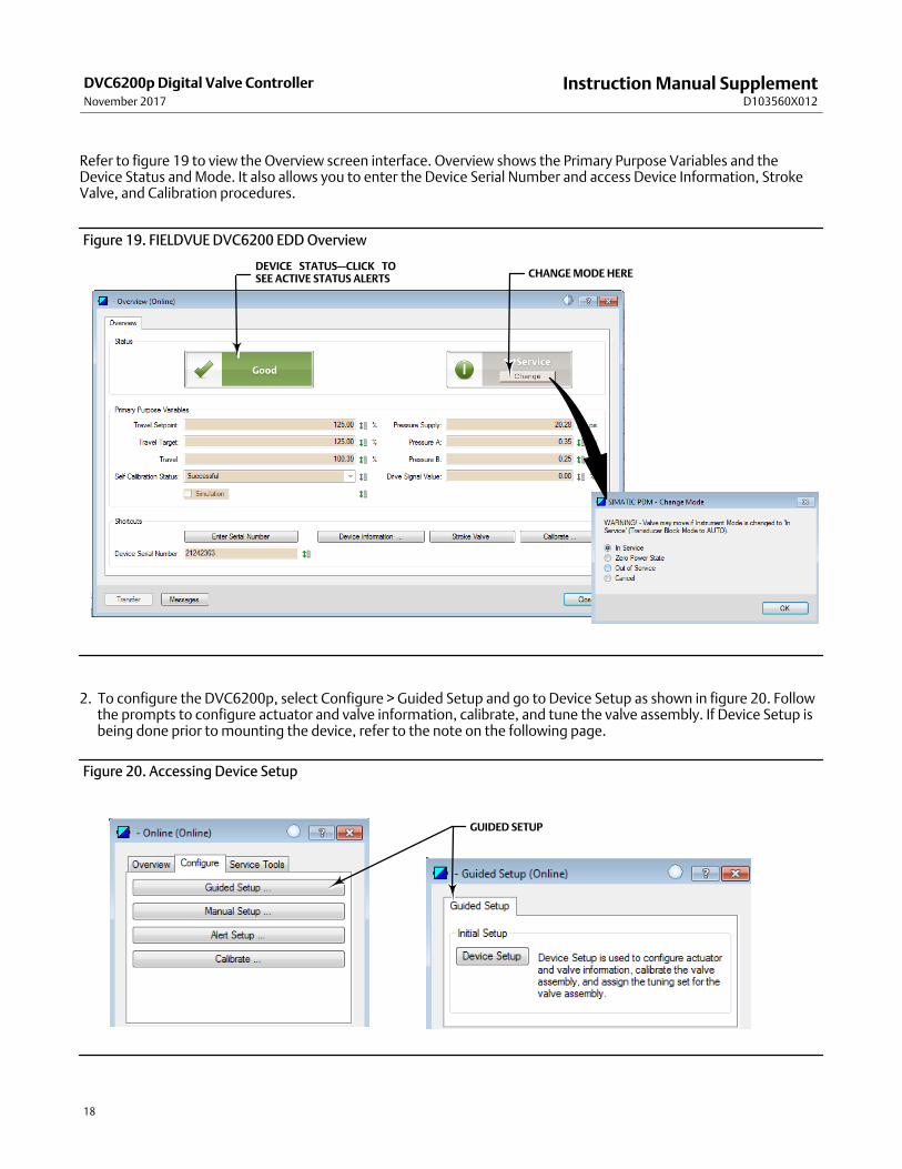
Refer to figure 19 to view the Overview screen interface. Overview shows the Primary Purpose Variables and theDevice Status and Mode. It also allows you to enter the Device Serial Number and access Device Information, StrokeValve, and Calibration procedures.
Figure 19. FIELDVUE DVC6200 EDD Overview
CHANGE MODE HEREDEVICE STATUS—CLICK TOSEE ACTIVE STATUS ALERTS
2. To configure the DVC6200p, select Configure > Guided Setup and go to Device Setup as shown in figure 20. Followthe prompts to configure actuator and valve information, calibrate, and tune the valve assembly. If Device Setup isbeing done prior to mounting the device, refer to the note on the following page.
Figure 20. Accessing Device Setup
GUIDED SETUP
Instruction Manual SupplementD103560X012
DVC6200p Digital Valve ControllerNovember 2017
19
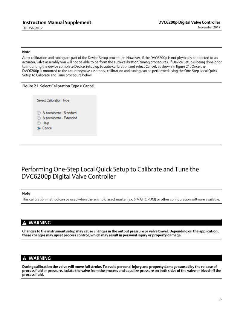
Note
Auto-calibration and tuning are part of the Device Setup procedure. However, if the DVC6200p is not physically connected to anactuator/valve assembly you will not be able to perform the auto-calibration/tuning procedures. If Device Setup is being done priorto mounting the device complete Device Setup up to auto-calibration and select Cancel, as shown in figure 21. Once theDVC6200p is mounted to the actuator/valve assembly, calibration and tuning can be performed using the One-Step Local QuickSetup to Calibrate and Tune procedure below.
Figure 21. Select Calibration Type > Cancel
Performing OneStep Local Quick Setup to Calibrate and Tune theDVC6200p Digital Valve Controller
Note
This calibration method can be used when there is no Class2 master (ex. SIMATIC PDM) or other configuration software available.
WARNING
Changes to the instrument setup may cause changes in the output pressure or valve travel. Depending on the application,these changes may upset process control, which may result in personal injury or property damage.
WARNING
During calibration the valve will move full stroke. To avoid personal injury and property damage caused by the release ofprocess fluid or pressure, isolate the valve from the process and equalize pressure on both sides of the valve or bleed off theprocess fluid.
Instruction Manual SupplementD103560X012
DVC6200p Digital Valve ControllerNovember 2017
20
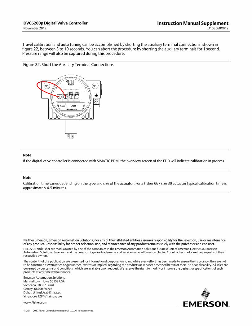
Travel calibration and auto tuning can be accomplished by shorting the auxiliary terminal connections, shown infigure 22, between 3 to 10 seconds. You can abort the procedure by shorting the auxiliary terminals for 1 second.Pressure range will also be captured during this procedure.
Figure 22. Short the Auxiliary Terminal Connections
Note
If the digital valve controller is connected with SIMATIC PDM, the overview screen of the EDD will indicate calibration in process.
Note
Calibration time varies depending on the type and size of the actuator. For a Fisher 667 size 30 actuator typical calibration time isapproximately 4-5 minutes.
Emerson Automation Solutions Marshalltown, Iowa 50158 USASorocaba, 18087 BrazilCernay, 68700 FranceDubai, United Arab EmiratesSingapore 128461 Singapore
www.Fisher.com
The contents of this publication are presented for informational purposes only, and while every effort has been made to ensure their accuracy, they are notto be construed as warranties or guarantees, express or implied, regarding the products or services described herein or their use or applicability. All sales aregoverned by our terms and conditions, which are available upon request. We reserve the right to modify or improve the designs or specifications of suchproducts at any time without notice.
� 2011, 2017 Fisher Controls International LLC. All rights reserved.
FIELDVUE and Fisher are marks owned by one of the companies in the Emerson Automation Solutions business unit of Emerson Electric Co. EmersonAutomation Solutions, Emerson, and the Emerson logo are trademarks and service marks of Emerson Electric Co. All other marks are the property of theirrespective owners.
Neither Emerson, Emerson Automation Solutions, nor any of their affiliated entities assumes responsibility for the selection, use or maintenanceof any product. Responsibility for proper selection, use, and maintenance of any product remains solely with the purchaser and end user.