fisher 657 diaphragm actuator sizes 30/30i through 70/70i ... · pdf file fisher™ 657...
TRANSCRIPT
www.Fisher.com
Fisher™ 657 Diaphragm ActuatorSizes 30/30i through 70/70i and 87
ContentsIntroduction 1. . . . . . . . . . . . . . . . . . . . . . . . . . . . . . . . .
Scope of Manual 1. . . . . . . . . . . . . . . . . . . . . . . . . . . . .Description 2. . . . . . . . . . . . . . . . . . . . . . . . . . . . . . . . .Specifications 2. . . . . . . . . . . . . . . . . . . . . . . . . . . . . . .Educational Services 3. . . . . . . . . . . . . . . . . . . . . . . . .Instructional Videos 3. . . . . . . . . . . . . . . . . . . . . . . . . .
Installation 3. . . . . . . . . . . . . . . . . . . . . . . . . . . . . . . . . .Mounting the Actuator on the Valve 4. . . . . . . . . . . .Discussion of Bench Set 5. . . . . . . . . . . . . . . . . . . . . . .Spring Verification 6. . . . . . . . . . . . . . . . . . . . . . . . . . .Installing the Stem Connector Assembly 7. . . . . . . . .Friction Discussion 8. . . . . . . . . . . . . . . . . . . . . . . . . . .Deadband Measurement 9. . . . . . . . . . . . . . . . . . . . . .Loading Connection 10. . . . . . . . . . . . . . . . . . . . . . . . .
Maintenance 11. . . . . . . . . . . . . . . . . . . . . . . . . . . . . . . .Actuator Maintenance 11. . . . . . . . . . . . . . . . . . . . . . .Top‐Mounted Handwheel Assembly 13. . . . . . . . . . .Side‐Mounted Handwheel for Sizes 34/34i
through 60/60i Actuators 15. . . . . . . . . . . . . . . . . .Side‐Mounted Handwheel for Sizes 70
and 87 Actuators 17. . . . . . . . . . . . . . . . . . . . . . . . .Casing‐Mounted Adjustable Travel Stops 19. . . . . . .
Parts Ordering 21. . . . . . . . . . . . . . . . . . . . . . . . . . . . . . .Parts Kits 21. . . . . . . . . . . . . . . . . . . . . . . . . . . . . . . . . . .
Kits for Side‐Mounted Handwheels 21. . . . . . . . . . . .Kits for Top‐Mounted Handwheels 21. . . . . . . . . . . . .
Parts List 22. . . . . . . . . . . . . . . . . . . . . . . . . . . . . . . . . . .Actuator Assembly (figures 6, 7, 8, 9, or 10) 22. . . . .
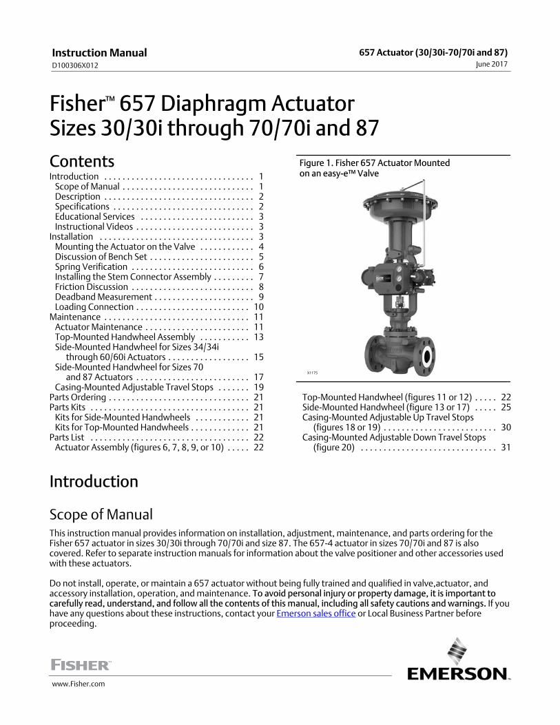
Figure 1. Fisher 657 Actuator Mounted on an easy‐e™ Valve
X1175
Top‐Mounted Handwheel (figures 11 or 12) 22. . . . .Side‐Mounted Handwheel (figure 13 or 17) 25. . . . .Casing‐Mounted Adjustable Up Travel Stops
(figures 18 or 19) 30. . . . . . . . . . . . . . . . . . . . . . . . .Casing‐Mounted Adjustable Down Travel Stops
(figure 20) 31. . . . . . . . . . . . . . . . . . . . . . . . . . . . . .
Introduction
Scope of ManualThis instruction manual provides information on installation, adjustment, maintenance, and parts ordering for theFisher 657 actuator in sizes 30/30i through 70/70i and size 87. The 657‐4 actuator in sizes 70/70i and 87 is alsocovered. Refer to separate instruction manuals for information about the valve positioner and other accessories usedwith these actuators.
Do not install, operate, or maintain a 657 actuator without being fully trained and qualified in valve,actuator, andaccessory installation, operation, and maintenance. To avoid personal injury or property damage, it is important tocarefully read, understand, and follow all the contents of this manual, including all safety cautions and warnings. If youhave any questions about these instructions, contact your Emerson sales office or Local Business Partner beforeproceeding.
Instruction ManualD100306X012
657 Actuator (30/30i-70/70i and 87)June 2017
Instruction ManualD100306X012
657 Actuator (30/30i-70/70i and 87)June 2017
2
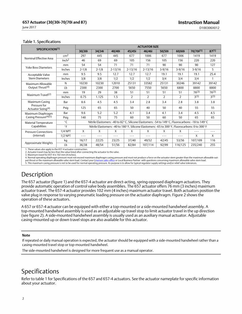
Table 1. Specifications
SPECIFICATION(1)ACTUATOR SIZE
30/30i 34/34i 40/40i 45/45i 46/46i 50/50i 60/60i 70/70i(1) 87(1)
Nominal Effective Areacm2 297 445 445 677 1006 677 1006 1419 1419
Inch2 46 69 69 105 156 105 156 220 220
Yoke Boss Diametersmm 54 54 71 71 71 90 90 90 127
Inches 2‐1/8 2‐1/8 2‐13/16 2‐13/16 2‐13/16 3‐9/16 3‐9/16 3‐9/16 5
Acceptable ValveStem Diameters
mm 9.5 9.5 12.7 12.7 12.7 19.1 19.1 19.1 25.4
Inches 3/8 3/8 1/2 1/2 1/2 3/4 3/4 3/4 1
Maximum AllowableOutput Thrust(4)
N 10230 10230 12010 25131 33582 25131 30246 39142 39142
Lb 2300 2300 2700 5650 7550 5650 6800 8800 8800
� Maximum Travel(2)mm 19 29 38 51 51 51 51 76(3) 76(3)
Inches 0.75 1.125 1.5 2 2 2 2 3(3) 3(3)
Maximum CasingPressure for
Actuator Sizing(4)
Bar 8.6 4.5 4.5 3.4 2.8 3.4 2.8 3.8 3.8
Psig 125 65 65 50 40 50 40 55 55
Maximum DiaphragmCasing Pressure(4)(5)
Bar 9.6 5.2 5.2 4.1 3.4 4.1 3.4 4.5 4.5
Psig 140 75 75 60 50 60 50 65 65
Material TemperatureCapabilities
�C Nitrile Elastomers: -40 to 82�C, Silicone Elastomers: -54 to 149�C, Fluorocarbons: -18 to 149�C
�F Nitrile Elastomers: -40 to 180�F, Silicone Elastomers: -65 to 300�F, Fluorocarbons: 0 to 300�F
Pressure Connections(internal)
1/4 NPT X X X X X X X ‐ ‐ ‐ ‐ ‐ ‐
1/2 NPT ‐ ‐ ‐ ‐ ‐ ‐ ‐ ‐ ‐ ‐ ‐ ‐ ‐ ‐ ‐ ‐ ‐ ‐ ‐ ‐ ‐ X X
Approximate Weightskg 16/17 22/25 23/25 37/40 49/52 42/45 53/56 107/109 116
Lb 36/38 48/54 51/56 82/84 107/114 92/99 116/125 235/240 255
1. These values also apply to the 657‐4 actuator construction.2. Actuator travel may be less than the value listed after connecting the actuator to the valve.3. Maximum travel for 657‐4 is 102 mm (4 inches).4. Normal operating diaphragm pressure must not exceed maximum diaphragm casing pressure and must not produce a force on the actuator stem greater than the maximum allowable output thrust or the maximum allowable valve stem load. Contact your Emerson sales office or Local Business Partner with questions concerning maximum allowable valve stem load.5. This maximum casing pressure is not to be used for normal operating pressure. Its purpose is to allow for typical regulator supply settings and/or relief valve tolerances.
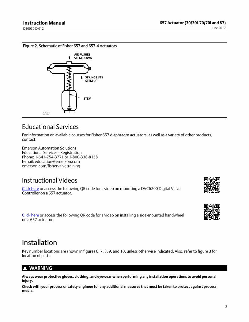
DescriptionThe 657 actuator (figure 1) and the 657‐4 actuator are direct‐acting, spring‐opposed diaphragm actuators. Theyprovide automatic operation of control valve body assemblies. The 657 actuator offers 76 mm (3 inches) maximumactuator travel. The 657‐4 actuator provides 102 mm (4 inches) maximum actuator travel. Both actuators position thevalve plug in response to varying pneumatic loading pressure on the actuator diaphragm. Figure 2 shows theoperation of these actuators.
A 657 or 657‐4 actuator can be equipped with either a top‐mounted or a side‐mounted handwheel assembly. Atop‐mounted handwheel assembly is used as an adjustable up travel stop to limit actuator travel in the up direction(see figure 2). A side‐mounted handwheel assembly is usually used as an auxiliary manual actuator. Adjustablecasing‐mounted up or down travel stops are also available for this actuator.
Note
If repeated or daily manual operation is expected, the actuator should be equipped with a side‐mounted handwheel rather than acasing‐mounted travel stop or top‐mounted handwheel.
The side‐mounted handwheel is designed for more frequent use as a manual operator.
SpecificationsRefer to table 1 for Specifications of the 657 and 657‐4 actuators. See the actuator nameplate for specific informationabout your actuator.
Instruction ManualD100306X012
657 Actuator (30/30i-70/70i and 87)June 2017
3
Figure 2. Schematic of Fisher 657 and 657‐4 Actuators
SPRING LIFTSSTEM UP
AIR PUSHESSTEM DOWN
STEM
AF3833‐AA0792‐2
Educational ServicesFor information on available courses for Fisher 657 diaphragm actuators, as well as a variety of other products,contact:
Emerson Automation SolutionsEducational Services - RegistrationPhone: 1-641-754-3771 or 1-800-338-8158E-mail: [email protected]/fishervalvetraining
Instructional VideosClick here or access the following QR code for a video on mounting a DVC6200 Digital ValveController on a 657 actuator.
Click here or access the following QR code for a video on installing a side-mounted handwheel on a 657 actuator.
InstallationKey number locations are shown in figures 6, 7, 8, 9, and 10, unless otherwise indicated. Also, refer to figure 3 forlocation of parts.
WARNING
Always wear protective gloves, clothing, and eyewear when performing any installation operations to avoid personalinjury.
Check with your process or safety engineer for any additional measures that must be taken to protect against processmedia.
Instruction ManualD100306X012
657 Actuator (30/30i-70/70i and 87)June 2017
4
If installing into an existing application, also refer to the WARNING at the beginning of the Maintenance section in thisinstruction manual.
CAUTION
To avoid parts damage, do not use an operating pressure that exceeds the Maximum Diaphragm Casing Pressure (table 1)or produces a force on the actuator stem greater than the Maximum Allowable Output Thrust (table 1) or the maximumallowable valve stem load. (Contact your Emerson sales office or Local Business Partner with questions concerningmaximum allowable valve stem load.)
� Valve/Actuator Assembly: If the actuator and valve are shipped together as a control valve assembly, it has beenadjusted at the factory, and may be installed in the pipeline. After installing the valve in the pipeline, refer to theLoading Connection procedures.
� Actuator Mounting: If the actuator is shipped separately or the actuator has been removed from the valve, it isnecessary to mount the actuator on the valve before placing the valve in the pipeline. Refer to the actuatormounting procedures before placing the valve in service. You may perform the Bench Set Spring Adjustmentprocedures in this section to confirm that the adjustment has not changed since it was shipped from the factory.
� Positioner: If a positioner is installed, or is to be installed on the actuator, refer to the positioner instruction manualfor installation. During the adjustment procedures, it will be necessary to provide a temporary loading pressure tothe actuator diaphragm.
Mounting the Actuator on the ValveThe 657 actuator spring loading pushes the actuator stem up towards the actuator diaphragm (see figure 2). Thisspring action moves the stem away from the valve while installing the actuator.
CAUTION
If the valve stem is allowed to remain in the up position (towards the actuator) during mounting, it can interfere with theactuator mounting, possibly damage valve stem threads or bend the valve stem. Be sure the valve stem is pushed down(into the valve body), away from the actuator while mounting.
Provide a temporary method of applying diaphragm loading pressure to the diaphragm to extend the actuator stemduring bench set spring adjustments.
1. Provide a vise or some other method of supporting the valve and the weight of the actuator during assembly. Fordirect or reverse acting valves, push the valve stem down away from the actuator while mounting the actuator.
2. Screw the stem locknuts all the way onto the valve stem. With the concave side of the travel indicator disk (key 14)facing the valve, install the travel indicator disk on the valve stem. (Note: The travel indicator disk is not used withsize 87 actuators.)
3. Lift or hoist the actuator onto the valve bonnet:
a. For size 87 actuators, insert the cap screws and tighten the hex nuts, securing the actuator to the bonnet.
b. For all other size actuators, screw the yoke locknut onto the valve bonnet and tighten the locknut. (Note: Onsmall size actuators, it may be necessary to remove the indicator disk and re‐install it while lowering the actuatoron to the valve because the disk will not go through the actuator yoke opening.)
Instruction ManualD100306X012
657 Actuator (30/30i-70/70i and 87)June 2017
5
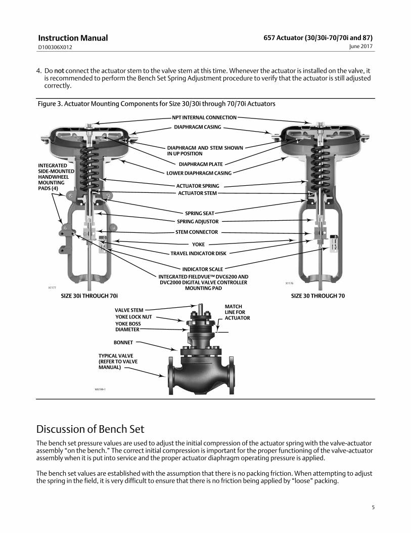
4. Do not connect the actuator stem to the valve stem at this time. Whenever the actuator is installed on the valve, itis recommended to perform the Bench Set Spring Adjustment procedure to verify that the actuator is still adjustedcorrectly.
Figure 3. Actuator Mounting Components for Size 30/30i through 70/70i Actuators
VALVE STEM
YOKE LOCK NUT
YOKE BOSSDIAMETER
BONNET
TYPICAL VALVE(REFER TO VALVEMANUAL)
W6199-1
MATCHLINE FORACTUATOR
NPT INTERNAL CONNECTION
DIAPHRAGM CASING
DIAPHRAGM AND STEM SHOWNIN UP POSITION
DIAPHRAGM PLATE
ACTUATOR SPRING
ACTUATOR STEM
SPRING SEAT
SPRING ADJUSTOR
STEM CONNECTOR
YOKE
TRAVEL INDICATOR DISK
INDICATOR SCALE
X1177
LOWER DIAPHRAGM CASING
X1176
SIZE 30i THROUGH 70i SIZE 30 THROUGH 70
INTEGRATED FIELDVUE™ DVC6200 ANDDVC2000 DIGITAL VALVE CONTROLLER
MOUNTING PAD
INTEGRATEDSIDE-MOUNTEDHANDWHEELMOUNTINGPADS (4)
Discussion of Bench SetThe bench set pressure values are used to adjust the initial compression of the actuator spring with the valve‐actuatorassembly “on the bench.” The correct initial compression is important for the proper functioning of the valve‐actuatorassembly when it is put into service and the proper actuator diaphragm operating pressure is applied.
The bench set values are established with the assumption that there is no packing friction. When attempting to adjustthe spring in the field, it is very difficult to ensure that there is no friction being applied by “loose” packing.
Instruction ManualD100306X012
657 Actuator (30/30i-70/70i and 87)June 2017
6
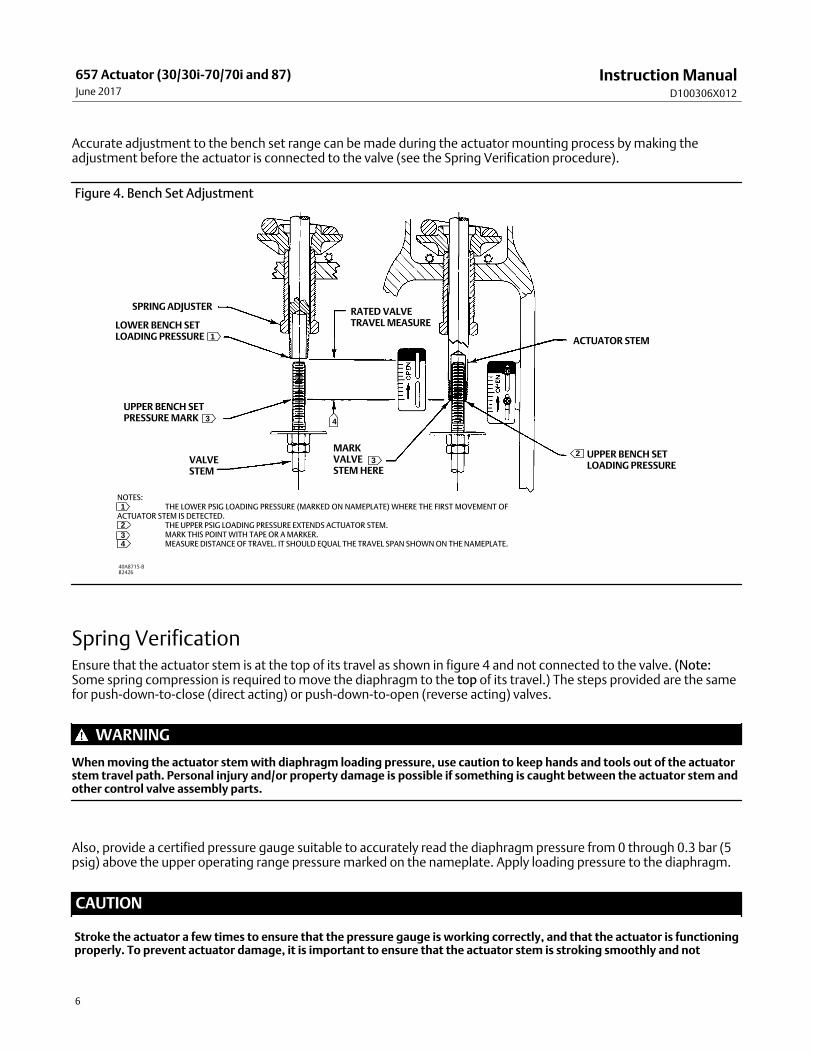
Accurate adjustment to the bench set range can be made during the actuator mounting process by making theadjustment before the actuator is connected to the valve (see the Spring Verification procedure).
Figure 4. Bench Set Adjustment
SPRING ADJUSTER
LOWER BENCH SETLOADING PRESSURE
UPPER BENCH SETPRESSURE MARK
VALVESTEM
RATED VALVETRAVEL MEASURE
MARKVALVESTEM HERE
UPPER BENCH SETLOADING PRESSURE
ACTUATOR STEM
NOTES:THE LOWER PSIG LOADING PRESSURE (MARKED ON NAMEPLATE) WHERE THE FIRST MOVEMENT OF
ACTUATOR STEM IS DETECTED.THE UPPER PSIG LOADING PRESSURE EXTENDS ACTUATOR STEM.MARK THIS POINT WITH TAPE OR A MARKER.MEASURE DISTANCE OF TRAVEL. IT SHOULD EQUAL THE TRAVEL SPAN SHOWN ON THE NAMEPLATE.
23
1
3 4
40A8715-BB2426
1
234
Spring Verification Ensure that the actuator stem is at the top of its travel as shown in figure 4 and not connected to the valve. (Note:Some spring compression is required to move the diaphragm to the top of its travel.) The steps provided are the samefor push-down-to-close (direct acting) or push-down-to-open (reverse acting) valves.
WARNING
When moving the actuator stem with diaphragm loading pressure, use caution to keep hands and tools out of the actuatorstem travel path. Personal injury and/or property damage is possible if something is caught between the actuator stem andother control valve assembly parts.
Also, provide a certified pressure gauge suitable to accurately read the diaphragm pressure from 0 through 0.3 bar (5psig) above the upper operating range pressure marked on the nameplate. Apply loading pressure to the diaphragm.
CAUTION
Stroke the actuator a few times to ensure that the pressure gauge is working correctly, and that the actuator is functioningproperly. To prevent actuator damage, it is important to ensure that the actuator stem is stroking smoothly and not
Instruction ManualD100306X012
657 Actuator (30/30i-70/70i and 87)June 2017
7
exhibiting binding or excessive friction. Binding or excessive friction could be an indicator of incorrect assembly ordamaged parts.
1. If not already accomplished, provide a temporary means of applying an adjustable loading pressure to the actuatorduring bench set adjustments.
2. Set the diaphragm loading pressure at 0 bar (0 psig). Then, slowly raise the pressure towards the lower bench setpressure, as indicated on the nameplate, while checking for the first linear movement of the actuator stem. Theactuator stem should show movement at the lower bench set pressure. If movement occurs before or after thelower pressure is reached, adjust the spring adjuster (see figure 4) into or out of the yoke until the actuator stem'smovement is first detected at the lower bench set pressure.
Note
Before turning the spring adjuster on size 70/70i or 87 actuators, assemble the stem connector around the actuator stem and theanti‐rotating lug on the yoke. Mark the actuator stem as a visual reference to verify that stem rotation does not occur. Remove thestem connector before rechecking the bench set.
3. Be sure the spring adjuster is adjusted to meet the requirements of step 2 above.
4. Apply the upper bench set pressure, as indicated on the nameplate. This pressure extends the actuator stem downtowards the valve. (Note: The actuator stem may slide over the valve stem as shown in figure 4.) At the end of theactuator stem, use a marker or a piece of tape to mark the valve stem (see figure 4). (Note: If the actuator stemdoes not pass over the valve stem, provide a method to mark this point of stem travel.)
5. Slowly decrease the diaphragm loading pressure to the lower bench set pressure, as indicated on the nameplate.
6. Measure the distance between the marker or tape on the valve stem to the end of the actuator stem. The distanceshould match the rated travel indicated on the nameplate.
7. If the measured travel matches the nameplate travel, bench set is complete. Proceed to the Installing the StemConnector Assembly subsection.
8. If the measured travel is not exact, consider the spring free-length and spring rate tolerances may produce a slightlydifferent bench set than specified. Contact your Emerson sales office or Local Business Partner for assistance.
Installing the Stem Connector AssemblyWhen installing the stem connector assembly (key 26), the actuator and valve stem threads should engage thethreads of the stem connector by the distance equal to the diameter of the stem.
WARNING
Install the stem connector securely before a positioner is mounted to the actuator and pressurized, using only aregulator-controlled air supply, not the positioner, to move the actuator stem.
To avoid personal injury or property damage, keep hands and tools out of the actuator stem travel path while applyingloading pressure to move the actuator stem in the following steps.
CAUTION
To avoid damaging the seating surfaces, do not rotate the valve plug while it is seated. Exercise care while installing thestem connector assembly to avoid damage to the valve plug stem and valve stem threads.
Instruction ManualD100306X012
657 Actuator (30/30i-70/70i and 87)June 2017
8
Note
Replacement stem connectors are an assembly of two stem connector halves, cap screws, and a spacer between the connectorhalves. Remove the spacer and discard, if present, before clamping the actuator and valve stems together. Use only a mated pairof stem connector halves.
1. If necessary, push the valve stem down so that it is touching the seat ring on direct acting valves. For reverse actingvalves, push the stem down to the open position.
If necessary, screw the valve stem locknuts down, away from the connector location. For all actuators except size 87,ensure that the travel indicator disk (key 14) is located on top of the locknuts.
2. Slowly increase the diaphragm pressure to the upper bench set pressure. This should be the same pressure used inthe Spring Verification steps, and it is marked on the nameplate.
3. Place the stem connector half with the threaded holes, approximately half way between the actuator and valvestems, and align with the stem connector. A slight change to loading pressure may be necessary to align thethreads. Refer to figures 6, 7, 8, 9, and 10 to help locate the connector position.
CAUTION
Incomplete engagement of either the valve stem or actuator stem in the stem connector can result in stripped threads orimproper operation. Be sure that the length of each stem clamped in the stem connector is equal to or greater than onediameter of that stem. Damage to threads on either stem or in the stem connector can cause the parts to be replacedprematurely. Do not loosen the cap screws when the stem connector has spring or loading pressure force applied.
4. Install the other half of the stem connector and insert the cap screws and tighten them while ensuring even spacingbetween the stem connector halves on all sides. If installing a positioner, also attach the feedback bracket at thesame time.
CAUTION
Over‐tightening the valve stem locknuts can make disassembly difficult.
5. Screw the valve stem locknuts up against the stem connector for the size 87 actuator. For all other actuator sizes,screw the valve stem locknuts up until the indicator disk contacts the bottom of the stem connector. Do notovertighten the locknuts.
6. Slowly stroke the valve from fully open to fully closed and verify full rated travel is achieved.
Be sure that the valve is in the closed position. Loosen the screws on the travel indicator scale (key 18), and align it withthe travel indicator disk (key 14) or stem connector for the size 87 actuator. Stroke the valve full travel to ensure thatthe travel matches the rated travel on the nameplate. If valve travel is not correct, repeat the stem connectorprocedure.
Friction DiscussionIf you are attempting to adjust the bench set after the actuator is connected to the valve and the packing tightened,you must take friction into account. Make the spring adjustment so full actuator travel occurs at the bench set values
Instruction ManualD100306X012
657 Actuator (30/30i-70/70i and 87)June 2017
9
(a) plus the friction force divided by the effective diaphragm area with increasing diaphragm pressure or (b) minus thefriction force divided by the effective diaphragm area with decreasing diaphragm pressure.
If the stem connector assembly has been installed, the valve friction may be determined by the following procedure:
1. Install a pressure gauge in the actuator loading pressure line that connects to the actuator diaphragm casing.
Note
Steps 2 and 4 require that you read and record the pressure shown on the pressure gauge.
2. Increase the actuator diaphragm pressure and read the diaphragm pressure as the actuator reaches a travelposition in the rated travel of the valve that does not contact a travel stop. Make a reference mark on the travelindicator scale using tape or some other method at this point.
3. Increase the actuator diaphragm pressure until the actuator is at a travel position greater than the positionreferenced in step 2 using the reference point to identify first movement.
4. Decrease the actuator diaphragm pressure and read the diaphragm pressure as the actuator returns to the positionreferenced in step 2.
The difference between the two diaphragm pressure readings is the change in the diaphragm pressure required toovercome the friction forces in the two directions of travel.
5. Calculate the actual friction force:
FrictionForce, = �0.5pounds
Differencein pressurereadings, psig
�
Effectivediaphragm area,inches2
Refer to table 1 for the effective diaphragm area.
It is difficult to rotate the spring adjustor (key 74, figures 6, 7, 8, 9, and 10) when the full actuator loading pressure isapplied to the actuator. Release the actuator loading pressure before adjusting. Then re-apply loading pressure tocheck the adjustment.
Note
For push‐down‐to‐close valves, the valve plug seat is the limit for downward travel and the actuator up‐stop is the limit for upward(away from the valve) movement. For push‐down‐to‐open valves, the actuator down stop is the limit for downward movement,and the valve seat is the limit for upward (away from the valve) movement.
Deadband MeasurementDeadband is caused by packing friction, unbalanced forces, and other factors in the control valve assembly. Deadbandis the range a measured signal can vary without initiating a response from the actuator (see figure 5). Each actuatorspring has a fixed spring rate (force divided by compression). You have verified that the right spring was installed in theactuator by completing the Spring Verification steps.
Deadband is one factor that affects the control valve assembly operation during automatic loop control. The controlloop tolerance for deadband varies widely depending on the loop response. Some common symptoms of the
Instruction ManualD100306X012
657 Actuator (30/30i-70/70i and 87)June 2017
10
deadband being too wide are no movement, a “jump” movement, or oscillating movements of the actuator duringautomatic loop control. The following steps are provided to determine the span of deadband. The percent ofdeadband is helpful in troubleshooting problems with the process control loop.
1. Start at a pressure near the lower bench set pressure, slowly increase pressure until the valve is approximately atmid‐travel. Note this pressure reading.
2. Slowly decrease pressure until movement of the valve stem is detected, and note this pressure.
3. The difference between these two pressures is deadband, in psi.
4. Calculate the percent of deadband by:
Deadband, psi Deadband = —————————————— = nn% Bench Set Span, psi
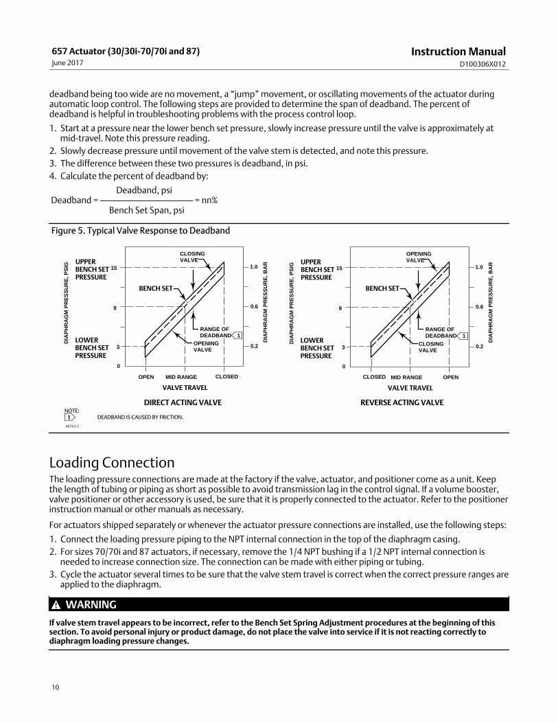
Figure 5. Typical Valve Response to Deadband
UPPER BENCH SETPRESSURE
LOWERBENCH SETPRESSURE
9
3
0
CLOSINGVALVE
15 1.0
0.6
0.2
OPENINGVALVE
OPENCLOSED MID RANGE
VALVE TRAVEL
DIA
PH
RA
GM
PR
ES
SU
RE
, PS
IG
DIA
PH
RA
GM
PR
ES
SU
RE
, BA
R
RANGE OFDEADBAND 1
UPPER BENCH SETPRESSURE
LOWERBENCH SETPRESSURE
9
3
0
CLOSINGVALVE
15 1.0
0.6
0.2OPENINGVALVE
OPEN CLOSEDMID RANGE
VALVE TRAVEL
DIA
PH
RA
GM
PR
ES
SU
RE
, PS
IG
DIA
PH
RA
GM
PR
ES
SU
RE
, BA
R
1NOTE:
DEADBAND IS CAUSED BY FRICTION.
A6763‐2
RANGE OFDEADBAND 1
DIRECT ACTING VALVE REVERSE ACTING VALVE
BENCH SET BENCH SET
Loading ConnectionThe loading pressure connections are made at the factory if the valve, actuator, and positioner come as a unit. Keepthe length of tubing or piping as short as possible to avoid transmission lag in the control signal. If a volume booster,valve positioner or other accessory is used, be sure that it is properly connected to the actuator. Refer to the positionerinstruction manual or other manuals as necessary.
For actuators shipped separately or whenever the actuator pressure connections are installed, use the following steps:
1. Connect the loading pressure piping to the NPT internal connection in the top of the diaphragm casing.
2. For sizes 70/70i and 87 actuators, if necessary, remove the 1/4 NPT bushing if a 1/2 NPT internal connection isneeded to increase connection size. The connection can be made with either piping or tubing.
3. Cycle the actuator several times to be sure that the valve stem travel is correct when the correct pressure ranges areapplied to the diaphragm.
WARNING
If valve stem travel appears to be incorrect, refer to the Bench Set Spring Adjustment procedures at the beginning of thissection. To avoid personal injury or product damage, do not place the valve into service if it is not reacting correctly todiaphragm loading pressure changes.
Instruction ManualD100306X012
657 Actuator (30/30i-70/70i and 87)June 2017
11
MaintenanceActuator parts are subject to normal wear and must be inspected and replaced when necessary. The frequency ofinspection and replacement depends on the severity of service conditions.
WARNING
Avoid personal injury or property damage from sudden release of process pressure or bursting of parts. Before performingany maintenance operations:
� Do not remove the actuator from the valve while the valve is still pressurized.
� Always wear protective gloves, clothing, and eyewear when performing any maintenance operations to avoid personalinjury.
� Disconnect any operating lines providing air pressure, electric power, or a control signal to the actuator. Be sure theactuator cannot suddenly open or close the valve.
� Use bypass valves or completely shut off the process to isolate the valve from process pressure. Relieve process pressurefrom both sides of the valve. Drain the process media from both sides of the valve.
� Vent the power actuator loading pressure and relieve any actuator spring precompression.
� Use lock‐out procedures to be sure that the above measures stay in effect while you work on the equipment.
� The valve packing box may contain process fluids that are pressurized, even when the valve has been removed from thepipeline. Process fluids may spray out under pressure when removing the packing hardware or packing rings, or whenloosening the packing box pipe plug.
� Check with your process or safety engineer for any additional measures that must be taken to protect against processmedia.
Actuator MaintenanceThis procedure describes how the actuator can be completely disassembled and assembled. When inspection orrepairs are required, disassemble only those parts necessary to accomplish the job; then, start the assembly at theappropriate step.
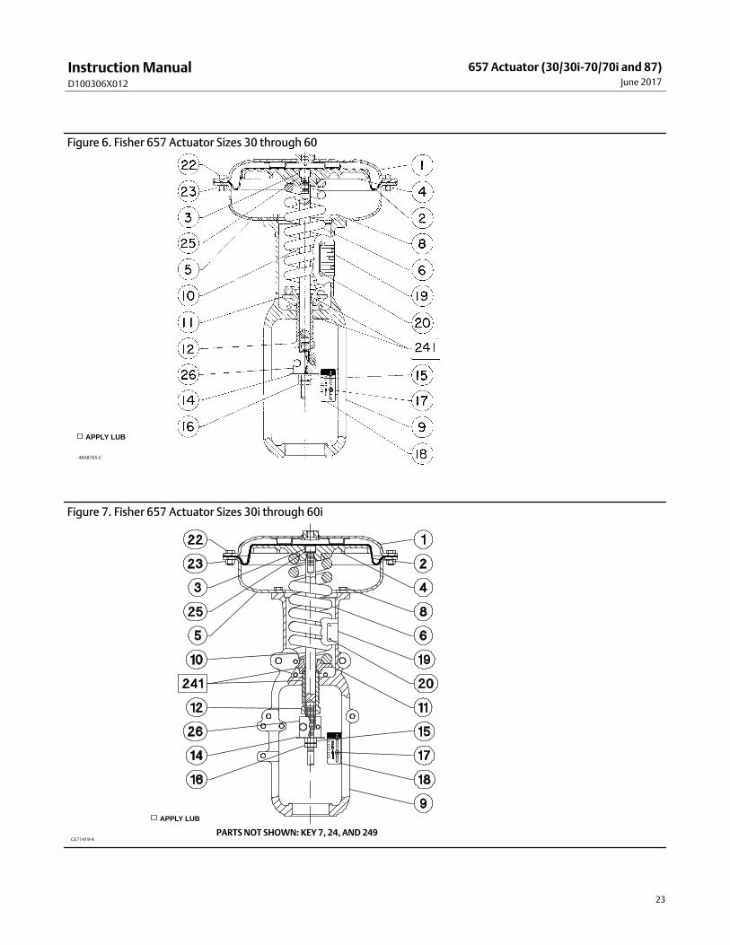
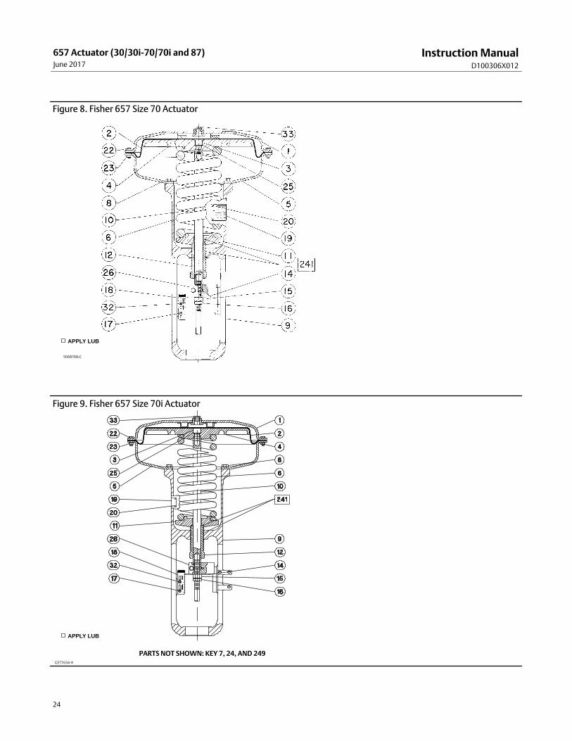
Key numbers refer to figures 6, 7, 8, 9, or 10 unless otherwise indicated. Figure 6 shows the size 30 through 60actuators, figure 7 shows the size 30i through 60i actuators, figure 8 illustrates the size 70 actuator, figure 9 illustratesthe size 70i actuator, and figure 10 shows the size 87 actuator.
Actuator Disassembly1. Bypass the control valve. Reduce the loading pressure to atmospheric, and remove the tubing or piping from the
upper diaphragm casing (key 1).
WARNING
To avoid personal injury from the precompressed spring force thrusting the upper diaphragm casing (key 1) away from theactuator, relieve spring compression (step 2, below), and carefully remove casing cap screws (key 22) (step 4, below).
2. Thread the spring adjuster (key 12) out of the yoke (key 9) until all spring compression is relieved.
3. If required, remove the actuator from the valve body by separating the stem connector (key 26) and removing theyoke locknut or, for the size 87 actuator, the stud bolt nuts. Separate the stem connector by loosening the stemnuts (keys 15 and 16) and unscrewing the two cap screws.
Instruction ManualD100306X012
657 Actuator (30/30i-70/70i and 87)June 2017
12
4. Remove the diaphragm casing cap screws and nuts (keys 22 and 23), then lift off the upper diaphragm casing (key 1).
5. Remove the actuator diaphragm (key 2).
6. Remove the diaphragm plate, actuator stem, and cap screw (keys 4, 10 and 3) as an assembly. This assembly can bebroken down further, if required, by removing the cap screw (key 3).
7. Remove the actuator spring (key 6) and the spring seat (key 11).
8. If required, remove the lower diaphragm casing (key 5) from the yoke (key 9) by loosening the cap screws (key 8)that hold it in place.
9. If required, remove the spring adjuster (key 12) by unscrewing it from the yoke (key 9).
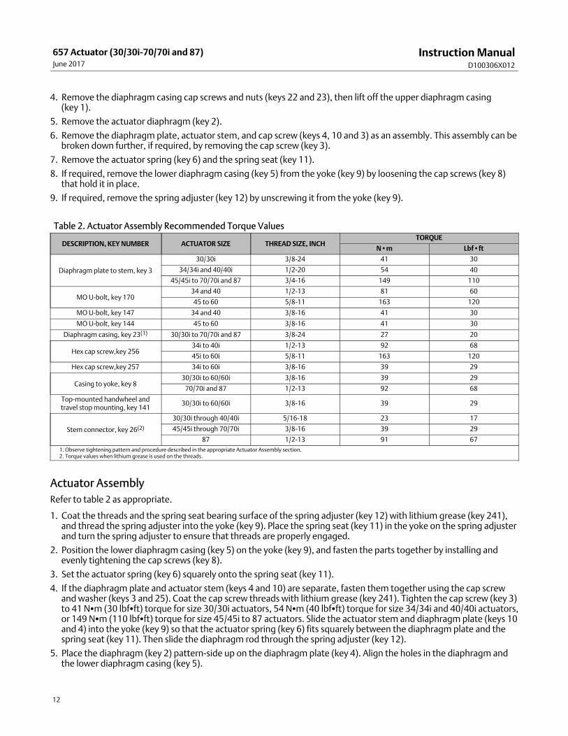
Table 2. Actuator Assembly Recommended Torque Values
DESCRIPTION, KEY NUMBER ACTUATOR SIZE THREAD SIZE, INCHTORQUE
N•m Lbf•ft
Diaphragm plate to stem, key 3
30/30i 3/8-24 41 30
34/34i and 40/40i 1/2-20 54 40
45/45i to 70/70i and 87 3/4-16 149 110
MO U-bolt, key 17034 and 40 1/2-13 81 60
45 to 60 5/8-11 163 120
MO U-bolt, key 147 34 and 40 3/8-16 41 30
MO U-bolt, key 144 45 to 60 3/8-16 41 30
Diaphragm casing, key 23(1) 30/30i to 70/70i and 87 3/8-24 27 20
Hex cap screw,key 25634i to 40i 1/2-13 92 68
45i to 60i 5/8-11 163 120
Hex cap screw,key 257 34i to 60i 3/8-16 39 29
Casing to yoke, key 830/30i to 60/60i 3/8-16 39 29
70/70i and 87 1/2-13 92 68
Top-mounted handwheel andtravel stop mounting, key 141
30/30i to 60/60i 3/8-16 39 29
Stem connector, key 26(2)
30/30i through 40/40i 5/16-18 23 17
45/45i through 70/70i 3/8-16 39 29
87 1/2-13 91 67
1. Observe tightening pattern and procedure described in the appropriate Actuator Assembly section.2. Torque values when lithium grease is used on the threads.
Actuator Assembly
Refer to table 2 as appropriate.
1. Coat the threads and the spring seat bearing surface of the spring adjuster (key 12) with lithium grease (key 241),and thread the spring adjuster into the yoke (key 9). Place the spring seat (key 11) in the yoke on the spring adjusterand turn the spring adjuster to ensure that threads are properly engaged.
2. Position the lower diaphragm casing (key 5) on the yoke (key 9), and fasten the parts together by installing andevenly tightening the cap screws (key 8).
3. Set the actuator spring (key 6) squarely onto the spring seat (key 11).
4. If the diaphragm plate and actuator stem (keys 4 and 10) are separate, fasten them together using the cap screwand washer (keys 3 and 25). Coat the cap screw threads with lithium grease (key 241). Tighten the cap screw (key 3)to 41 N�m (30 lbf�ft) torque for size 30/30i actuators, 54 N�m (40 lbf�ft) torque for size 34/34i and 40/40i actuators,or 149 N�m (110 lbf�ft) torque for size 45/45i to 87 actuators. Slide the actuator stem and diaphragm plate (keys 10and 4) into the yoke (key 9) so that the actuator spring (key 6) fits squarely between the diaphragm plate and thespring seat (key 11). Then slide the diaphragm rod through the spring adjuster (key 12).
5. Place the diaphragm (key 2) pattern‐side up on the diaphragm plate (key 4). Align the holes in the diaphragm andthe lower diaphragm casing (key 5).
Instruction ManualD100306X012
657 Actuator (30/30i-70/70i and 87)June 2017
13
6. Position the upper diaphragm casing (key 1) on the diaphragm (key 2) and align the holes.
Note
When you replace actuator diaphragms in the field, take care to ensure the diaphragm casing bolts are tightened to the properload to prevent leakage, but not crush the material. Perform the following tightening sequence with a manual torque wrench forsize 30/30i‐70/70i and 87 actuators.
CAUTION
Over‐tightening the diaphragm casing cap screws and nuts (keys 22 and 23) can damage the diaphragm. Do not exceed 27N�m (20 lbf�ft) torque.
Note
Do not use lubricant on these bolts and nuts. Fasteners must be clean and dry.
7. Insert the cap screws (key 22), and tighten the hex nuts (key 23) in the following manner. The first four hex nutstightened should be diametrically opposed and 90 degrees apart. Tighten these four hex nuts to 13 N�m (10 lbf�ft).
8. Tighten the remaining hex nuts in a clockwise, criss‐cross pattern to 13 N�m (10 lbf�ft).
9. Repeat this procedure by tightening four hex nuts, diametrically opposed and 90 degrees apart, to a torque of 27N�m (20 lbf�ft).
10. Tighten the remaining hex nuts in a clockwise, criss‐cross pattern to 27 N�m (20 lbf�ft).
11. After the last hex nut is tightened to 27 N�m (20 lbf�ft), all of the hex nuts should be tightened again to 27 N�m(20 lbf�ft) in a circular pattern around the bolt circle.
12. Once completed, no more tightening is recommended.
13. Mount the actuator on the valve by following the procedures in the Installation section.
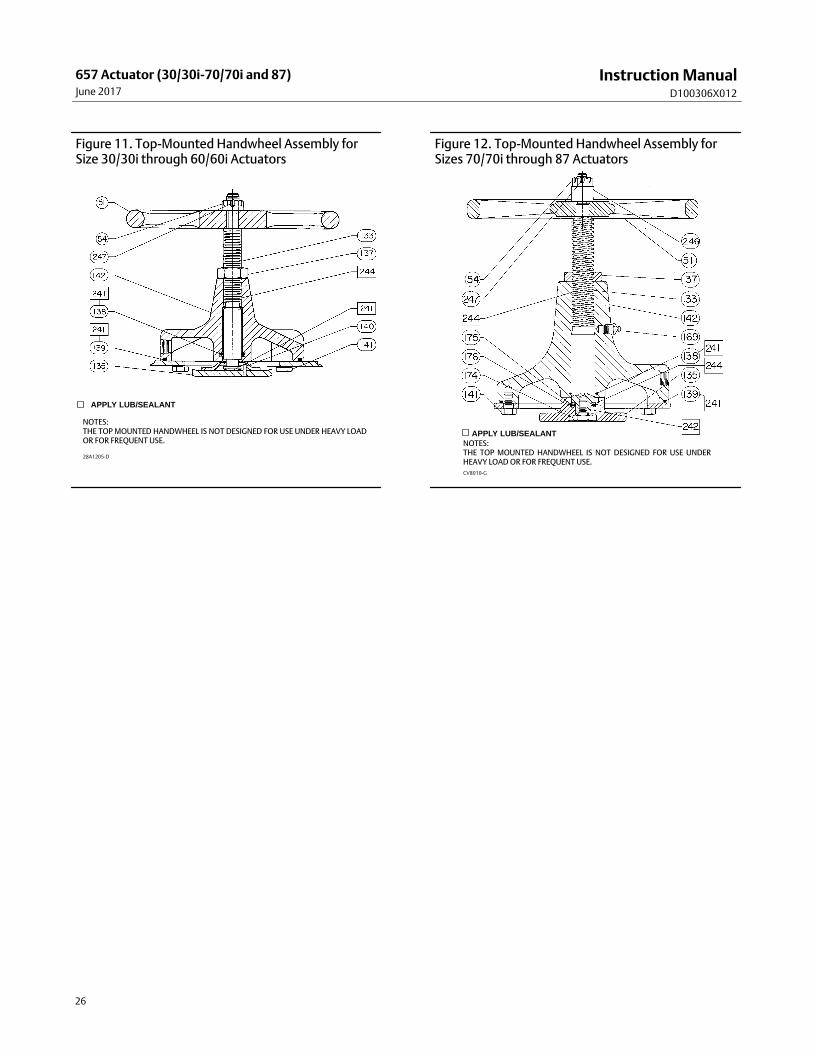
Top‐Mounted Handwheel AssemblyA top‐mounted handwheel assembly (figures 11 and 12) is usually used as an adjustable casing‐mounted up travelstop to limit full retraction of the actuator stem. Turning the handwheel clockwise moves the the handwheel stem(key 133, figures 11 and 12) down, compressing the spring.
Instructions are given below for complete disassembly and assembly of the top‐mounted handwheel assembly.Perform the disassembly only as far as necessary to accomplish the required maintenance; then, begin the assembly atthe appropriate step.
Key numbers refer to figure 11 (sizes 30/30i through 60/60i) and figure 12 (sizes 70/70i and 87), unless otherwiseindicated.
Disassembly for Top‐Mounted Handwheel1. Turn the handwheel (key 51) counter‐clockwise so that the handwheel assembly is not causing any spring
compression.
2. Bypass the control valve, reduce loading pressure to atmospheric, and remove the tubing or piping from the upperhandjack body (key 142, figures 11 or 12).
WARNING
To avoid personal injury from the precompressed spring force thrusting the upper diaphragm casing (key 1) away from theactuator, thread the spring adjuster (key 12) out of the yoke until all spring compression is relieved, then carefully removecasing cap screws (key 22).
Instruction ManualD100306X012
657 Actuator (30/30i-70/70i and 87)June 2017
14
3. Remove the diaphragm casing cap screws and nuts (keys 22 and 23, figures 6, 7, 8, 9, or 10), and lift off the upperdiaphragm casing and handwheel assembly.
4. If necessary, the handwheel assembly can be separated from the diaphragm casing by removing the cap screws(key 141). This may be necessary to replace the O‐ring (key 139), or for ease of handling.
5. Loosen the travel stop locknut (key 137), and turn the handwheel (key 51) counter‐clockwise. Remove the cotterpin and stop nut (keys 247 and 54), then lift off the handwheel.
6. Unscrew the travel stop locknut (key 137) from the handwheel stem (key 133), and turn the stem out of the bottomof the body (key 142). A screwdriver slot is provided on the top of the stem for this purpose.
7. Replace the O‐ring (key 138) in the body (key 142).
8. For a handwheel assembly used on sizes 30/30i through 60/60i actuators, complete the disassembly by driving outthe groove pin (key 140, figure 11) and sliding the pusher plate (key 135, figure 11) off the stem.
For a handwheel assembly used on a sizes 70/70i or 87 actuator, complete the disassembly by unscrewing theretaining screw (key 174, figure 12) and removing the thrust bearing and pusher plate (keys 175 and 135, figure 12).Because the retaining screw (key 174) has left‐hand threads, turn clockwise to loosen.
Assembly for Top‐Mounted Handwheel1. For a handwheel assembly used on sizes 30/30i through 60/60i actuators, coat the end of the handwheel stem (key
133, figure 11) with anti‐seize lubricant (key 244). Slide the pusher plate (key 135, figure 11), onto the stem, anddrive in the groove pin (key 140, figure 11) to lock the pieces together.
For a handwheel assembly used on a sizes 70/70i or 87 actuator, pack the thrust bearing (key 175, figure 12) withanti‐seize lubricant (key 244). Place the thrust bearing in the pusher plate (key 135, figure 12), slide the two parts ontothe handwheel stem (key 133). Coat the retaining screw threads with thread locking sealant (key 242). Insert andtighten the retaining screw (key 174, figure 12).
2. Coat the O‐ring (key 138) with lithium grease (key 241), and insert the O‐ring in the body (key 142).
3. Coat the threads of the handwheel stem (key 133) with anti‐seize lubricant (key 244). Screw the stem into the body(key 142).
4. Thread the travel stop locknut (key 137) onto the handwheel stem (key 133).
5. Place the handwheel (key 51), and the stop nut (key 54) on the handwheel stem (key 133). Tighten the hex nut tofasten the parts together. Secure the nut with the cotter pin (key 247).
6. If the body (key 142) was separated from the upper diaphragm casing (key 1, figures 6, 7, 8, 9, or 10), lubricate theO‐ring (key 139) with lithium grease (key 241), and place the O‐ring in the body. Align the holes in the diaphragmcasing and the body, insert the cap screws (key 141), and tighten them evenly following a crisscross pattern toensure a proper seal.
7. Position the upper diaphragm casing (key 1) on the diaphragm (key 2) and align the holes.
Note
When you replace actuator diaphragms in the field, take care to ensure the diaphragm casing bolts are tightened to the properload to prevent leakage, but not crush the material. Perform the following tightening sequence with a manual torque wrench forsize 30/30i‐70/70i and 87 actuators.
CAUTION
Over‐tightening the diaphragm casing cap screws and nuts (keys 22 and 23) can damage the diaphragm. Do not exceed 27N�m (20 lbf�ft) torque.
Instruction ManualD100306X012
657 Actuator (30/30i-70/70i and 87)June 2017
15
Note
Do not use lubricant on these bolts and nuts. Fasteners must be clean and dry.
8. Insert the cap screws (key 22), and tighten the hex nuts (key 23) in the following manner. The first four hex nutstightened should be diametrically opposed and 90 degrees apart. Tighten these four hex nuts to 13 N�m (10 lbf�ft).
9. Tighten the remaining hex nuts in a clockwise, criss‐cross pattern to 13 N�m (10 lbf�ft).
10. Repeat this procedure by tightening four hex nuts, diametrically opposed and 90 degrees apart, to a torque of 27N�m (20 lbf�ft).
11. Tighten the remaining hex nuts in a clockwise, criss‐cross pattern to 27 N�m (20 lbf�ft).
12. After the last hex nut is tightened to 27 N�m (20 lbf�ft), all of the hex nuts should be tightened again to 27 N�m(20 lbf�ft) in a circular pattern around the bolt circle.
13. Once completed, no more tightening is recommended.
14. Mount the actuator on the valve following the procedures in the Installation section.
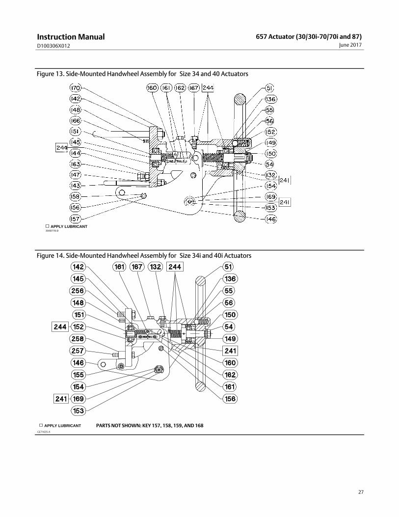
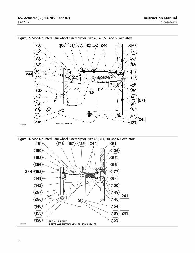
Side‐Mounted Handwheel for Sizes 34 through 60 and 34i through 60iActuatorsA side-mounted handwheel assembly is normally used as a manual actuator for sizes 34 through 60 (figures 13 and 15)and 34i through 60i actuators (figures 14 and 16). Turning the handwheel counter-clockwise past the neutral positionopens the valve. Two levers (key 146, figures 13, 14, 15, and 16) on a handwheel assembly operate the valve bymoving the valve stem.
Instructions are given below for complete disassembly and assembly. Perform the disassembly only as far as necessaryto accomplish the required maintenance; then begin the assembly at the appropriate step.
Disassembly for Side-Mounted Handwheel (Sizes 34-60 and 34i-60i)1. Use step a. for size 34 through size 60 actuators, and use step b. for sizes 34i through 60i.
a. For Size 34 through 60: If desired, the handwheel assembly can be removed from the actuator yoke. To do this,remove the hex nuts (keys 147 and 170) from the U-bolts (key 166 and 143) that hold the assembly to the yokefor the size 30 and size 40. Remove the hex nuts (key 144 and 170) from the U-bolts (key 166 and 143) that holdthe assembly to the yoke for the size 45 through size 60.
b. For Size 34i through 60i: If desired, the handwheel assembly can be removed from the actuator yoke. To do this,remove the cap screws (key 256 and 257) and spacers (key 258) that hold the assembly to the yoke for the size30i through size 60i.
2. Remove the retaining ring (key 154) and drive out the lever pivot pin (key 153).
3. Two screws (key 156) hold the right- and left-hand levers (key 146) together. Remove the screw from the top of thelevers so that the levers will drop down out of the assembly. Disassemble further, if necessary, by removing theother screw.
4. Remove the screw (key 161) and pointer mounting bolt (key 159, not shown) located behind the pointer (key 160).
5. Remove the stop nut (key 54), lockwasher (key 150), and washer (key 149). Then remove the handwheel (key 51),being careful not to lose the small ball (key 55) and spring (key 56).
6. Loosen the locking set screw (key 168, figure 16). Then, using a suitable tool, unscrew the bearing retainer (key136).
Instruction ManualD100306X012
657 Actuator (30/30i-70/70i and 87)June 2017
16
7. Pull the handwheel screw assembly (key 145) out of the handwheel body. The operating nut (key 132) will comeout with the screw. Also remove the bushing (key 151, figure 13 or 14) on size 34 and 40.
8. If required, remove the two ball bearings (key 152), one from the bearing retainer and the other from thehandwheel body.
Assembly for Side-Mounted Handwheel (Sizes 34-60 and 34i-60i)
Click here or access the following QR code for a video on installing a side-mounted handwheel on a 657 actuator.
1. Pack the ball bearings (key 152) with anti-seize lubricant (key 244). Insert one bearing and the bushing (key 151,figure 13 or 14) into the handwheel body (key 142). The bushing is not used in a handwheel assembly for sizes45/45i through 60/60i actuators.
2. Coat the handwheel screw assembly (key 145) threads with anti-seize lubricant (key244), and thread the operatingnut (key 132) onto the screw. Slide the second ball bearing (key 152) onto the screw, and insert the end of thescrew into either the bushing (key 151, figure 13 or 14) for sizes 34/34i and 40/40i, or into the bearing for sizes45/45i through 60/60i.
3. Thread the bearing retainer (key 136) into the body (key 142). Completely tighten the bearing retainer, and thenloosen it one-quarter turn. Tighten the set screw (key 168, figure 13 or 14) to hold the bearing retainer in place.
4. Coat the groove in the handwheel body (key 142) with lithium grease (key 241). Insert the spring (key 56) and ball(key 55) into the handwheel (key 51).Holding the ball and spring in the handwheel, put the handwheel, the washer(key 149), the lockwasher (key 150), and the stop nut (key 54) onto the end of the end of the handwheel screw (key145). Tighten the stop nut.
5. Position the pointer mounting bolt (key 159, not shown) and pointer (key 160). Insert and tighten the screw (key161).
6. Assemble the two levers (key 146) with the cap screws (key 156) for handwheel assemblies for sizes 45/45i, 50/50i,and 60/60i actuators, or with the machine screws (key 156) for handwheel assemblies on sizes 34/34i and 40/40iactuators.
7. Use step a. for size 34 through size 60 actuators, and use step b. for sizes 34i through 60i.
a. For Size 34 through 60: If the handwheel assembly was removed from the yoke (key 9, figures 6, 8, or 10),remount the handjack assembly to the yoke using the dowel pins for alignment. For the size 34 and size 40,position the U-bolts and J-bolts (keys 166 and 143) on the yoke, and hand-tighten the hex nuts (keys 170 and147) to hold the handwheel assembly in position. For the size 45 through size 60, position the U-bolts (keys 166and 143) on the yoke, and hand-tighten the hex nuts (keys 170 and 144) to hold the handwheel assembly inposition. Cap screws (key 163) should be tight against the yoke legs to provide stability. Tighten the nuts (key144 for size 30 and size 40, key 158 for the size 45 through size 60). For the size 34 and size 40 finish tighteningthe U-bolt nuts to 81 N•m [60lbf•ft] (key170) and 41 N•m [30 lbf•ft] (key 147). For the sizes 45 through 60finish tightening the U-bolt nuts to 163 N•m [120lbf•ft] (key170) and 41 N•m [30 lbf•ft] (key 144). Be sure thehandwheel assembly remains flat against the mounting pad and perpendicular to the yoke.
b. For Size 34i through 60i: If the handwheel assembly was removed from the yoke (key 9, figures 7, 9, or 10),remount the handjack assembly to the yoke using the dowel pins for alignment. Position the upper cap screws(key 256) on the assembly and hand-tighten to hold the handwheel assembly in position. Place the spacers (key258) between the yoke and handjack assembly, position cap screws (key 257), and hand-tighten. For the size34i and size 40i, finish tightening the cap screws (key 256) to 81 N•m [60 lbf•ft] and (key 257) to 41 N•m [30 lbf•ft]. For the sizes 45i through 60i, finish tightening the cap screws (key 256) to 163 N•m [120 lbf•ft] and(key 257)to 41 N•m [30 lbf•ft].
8. Position the levers (key 146) as shown in figures 11 or 12. Insert the lever pivot pin (key 153), and snap the retainingring (key 154) onto the lever pivot pin.
Instruction ManualD100306X012
657 Actuator (30/30i-70/70i and 87)June 2017
17
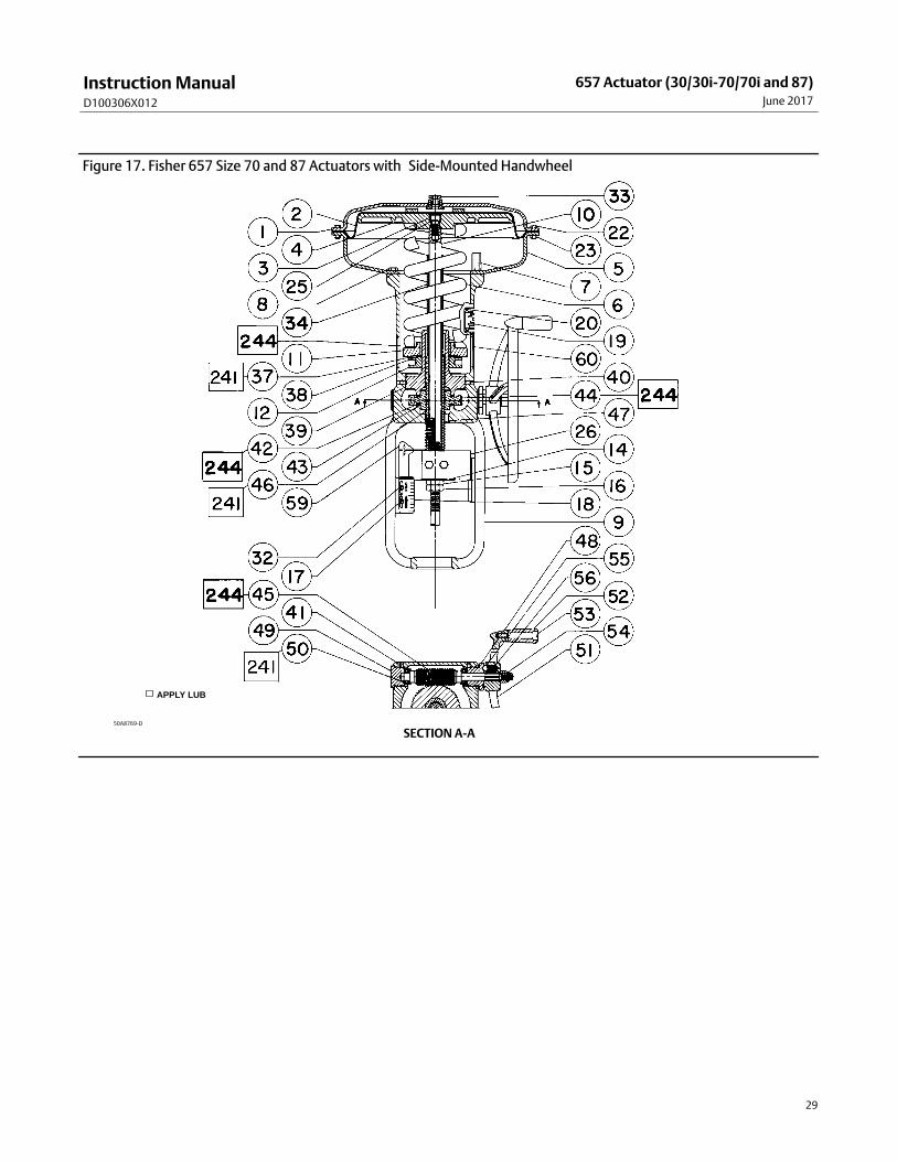
Side‐Mounted Handwheel for Sizes 70 and 87 ActuatorsA side‐mounted handwheel assembly (figure 17) is normally used as a manual actuator for sizes 70 and 87 actuators.Turning the handwheel counter‐clockwise past the neutral position opens the valve body. A pair of sleeves (keys 34and 46, figure 17) operates the valve by moving the valve stem.
Instructions are given below for complete disassembly and assembly. Perform the disassembly only as far as necessaryto accomplish the required maintenance; and then begin the assembly at the appropriate step.
Key numbers refer to figures 8 or 10, and 13.
Disassembly for Side‐Mounted Handwheel (Size 70 & 87)1. Bypass the control valve, reduce loading pressure to atmospheric, and remove the tubing or piping from the upper
diaphragm casing (key 1).
2. Remove cover band (key 60), and relieve spring compression by turning the spring adjuster (key 12)counter‐clockwise.
3. Remove the cap screws and casing screws and nuts (keys 22 and 23), lift off the upper diaphragm casing (key 1),and remove the diaphragm (key 2).
4. Remove the cap screw (key 3) and the washer (key 25), then take off the diaphragm plate (key 4).
5. Remove the actuator spring (key 6), the upper sleeve (key 34), and the spring seat (key 11) from the yoke cylinder.This exposes the needle bearing and races (keys 37 and 38).
6. Separate the halves of the stem connector assembly (key 26) by removing the two cap screws. Remove theactuator stem (key 10).
7. Remove the travel indicator (key 14).
CAUTION
To avoid possible product damage, do not move the neutral indicator scale after completing the following step.
8. Turn the handwheel to raise the lower sleeve (key 46) until it is free of the worm gear (key 44). Lift out the lowersleeve and the key (key 47). DO NOT move the neutral indicator scale (key 59).
9. Loosen two set screws (key 40), then unscrew the bearing retainer flange (key 39) and the attached spring adjuster(key 12), using a suitable tool in the open neck of the flange. Take out the gear and two needle bearings (key 42),one on each side of the gear.
10. Remove the spring adjuster (key 12) from the bearing retainer flange (key 39). If desired, the worm shaft (key 45)and associated parts can be disassembled to replace or lubricate them. To do so, first remove the stop nut (key 54)and the handwheel (key 51). Do not lose the small ball (key 55) and spring (key 56).
11. Loosen the two set screws (key 41), and unscrew the front and back retainers (keys 48 and 49). The ball bearings(key 50) will come out with the retainers. Remove the worm shaft (key 45).
Assembly for Side‐Mounted Handwheel (Size 70 & 87)1. The front and back retainers (keys 48 and 49) each have a slot in their threads for a set screw (key 41). Pack the ball
bearings (key 50) with anti‐seize lubricant (key 244), and insert one ball bearing into the back retainer (key 49) asshown in figure 17.
2. Thread the back retainer and ball bearing (keys 49 and 50) into the yoke (key 9). Align the slot in the bearingretainer with the set screw hole in the yoke, insert the set screw (key 41), and tighten it.
Instruction ManualD100306X012
657 Actuator (30/30i-70/70i and 87)June 2017
18
3. Coat the worm shaft (key 45) threads with anti‐seize lubricant (key 244), and slide the shaft into the yoke so thatthe end of the shaft fits snugly into the back retainer (key 49).
4. Insert the bearing into the front retainer (key 48), and thread the retainer and ball bearing into the yoke (key 9).Align the slot in the retainer with the hole in the yoke, insert the set screw (key 41), and tighten it.
5. Put the spring and ball (keys 56 and 55) into the handwheel (key 51). Slide the handwheel onto the worm shaft (key45). Thread the stop nut (key 54) onto the shaft.
6. Pack the two needle bearings (key 42) and coat the worm gear (key 44) threads with anti‐seize lubricant (key 244).Insert the key (key 47), the bearings, and the gear into the yoke (key 9) as shown in figure 17.
7. Slots are cut into the threads of the bearing retainer flange (key 39). Thread the flange into the yoke (key 9) so thatthe slots and the holes for the set screws (key 40) align. Insert the screws, and tighten them.
8. The lower sleeve (key 46) has milled slots in one end. Coat the sleeve threads with lithium grease (key 241), thenslide the end of the lower sleeve with the milled slots into the bearing retainer flange (key 39).
9. Turn the handwheel (key 51), and feed the sleeve through the gear so that the slot in the lower sleeve (key 46)engages the key (key 47) in the yoke (key 9). Continue turning the handwheel until the lower sleeve protrudes 93.7mm (3.69 inches) below the surface of the yoke. The pin in the side of the lower sleeve should line up with theextension on the neutral indicator.
10. Slide the square end of the actuator stem (key 10) through the lower sleeve (key 46) so the stem contacts thevalve stem. Clamp both stems in the two halves of the stem connector (key 26). The stem connector should not becloser than 3.2 mm (1/8 inches) to the lower sleeve when the actuator stem is in the retracted position. Thisadjustment will provide approximately 3.2 mm (1/8 inches) of free travel of the lower sleeve in either direction formanual operation. Fasten the stem connector halves together with the cap screws.
11. Pack the needle bearing and race (keys 37 and 38) with lithium grease (key 241), and slide the bearing onto thespring adjuster (key 12).
12. Put the spring seat and actuator spring (keys 11 and 6) into the yoke (key 9). Slide the upper sleeve (key 34) ontothe actuator stem (key 10).
13. Put the diaphragm plate and washer (keys 4 and 25) onto the actuator stem (key 10). Insert and tighten the capscrew (key 3) to fasten the parts together.
14. Place the diaphragm (key 2) pattern‐side up onto the diaphragm plate (key 4). Align the holes in the diaphragmand the lower diaphragm casing (key 5).
15. Position the upper diaphragm casing (key 1) onto the diaphragm (key 2) and align the holes.
Note
When you replace actuator diaphragms in the field, take care to ensure the diaphragm casing bolts are tightened to the properload to prevent leakage, but not crush the material. Perform the following tightening sequence with a manual torque wrench forsize 30‐70, 30i-70i, and 87 actuators.
CAUTION
Over‐tightening the diaphragm casing cap screws and nuts (keys 22 and 23) can damage the diaphragm. Do not exceed 27N�m (20 lbf�ft) torque.
Note
Do not use lubricant on these bolts and nuts. Fasteners must be clean and dry.
Instruction ManualD100306X012
657 Actuator (30/30i-70/70i and 87)June 2017
19
16. Insert the cap screws (key 22), and tighten the hex nuts (key 23) in the following manner. The first four hex nutstightened should be diametrically opposed and 90 degrees apart. Tighten these four hex nuts to 13 N�m (10 lbf�ft).
17. Tighten the remaining hex nuts in a clockwise, criss‐cross pattern to 13 N�m (10 lbf�ft).
18. Repeat this procedure by tightening four hex nuts, diametrically opposed and 90 degrees apart, to a torque of 27N�m (20 lbf�ft).
19. Tighten the remaining hex nuts in a clockwise, criss‐cross pattern to 27 N�m (20 lbf�ft).
20. After the last hex nut is tightened to 27 N�m (20 lbf�ft), all of the hex nuts should be tightened again to 27 N�m(20 lbf�ft) in a circular pattern around the bolt circle.
21. Once completed, no more tightening is recommended.
22. Mount the actuator onto the valve, following the procedures in the Installation section.
23. Return the actuator to service after completing the Loading Connection procedure in the Installation section andthe procedures in the Adjustments section.
Casing‐Mounted Adjustable Travel Stops
Note
If repeated or daily manual operation is expected, the actuator should be equipped with a manual top‐mounted or side‐mountedhandwheel. Refer to the Top‐Mounted Handwheel and Side‐Mounted Handwheel sections of this instruction manual.
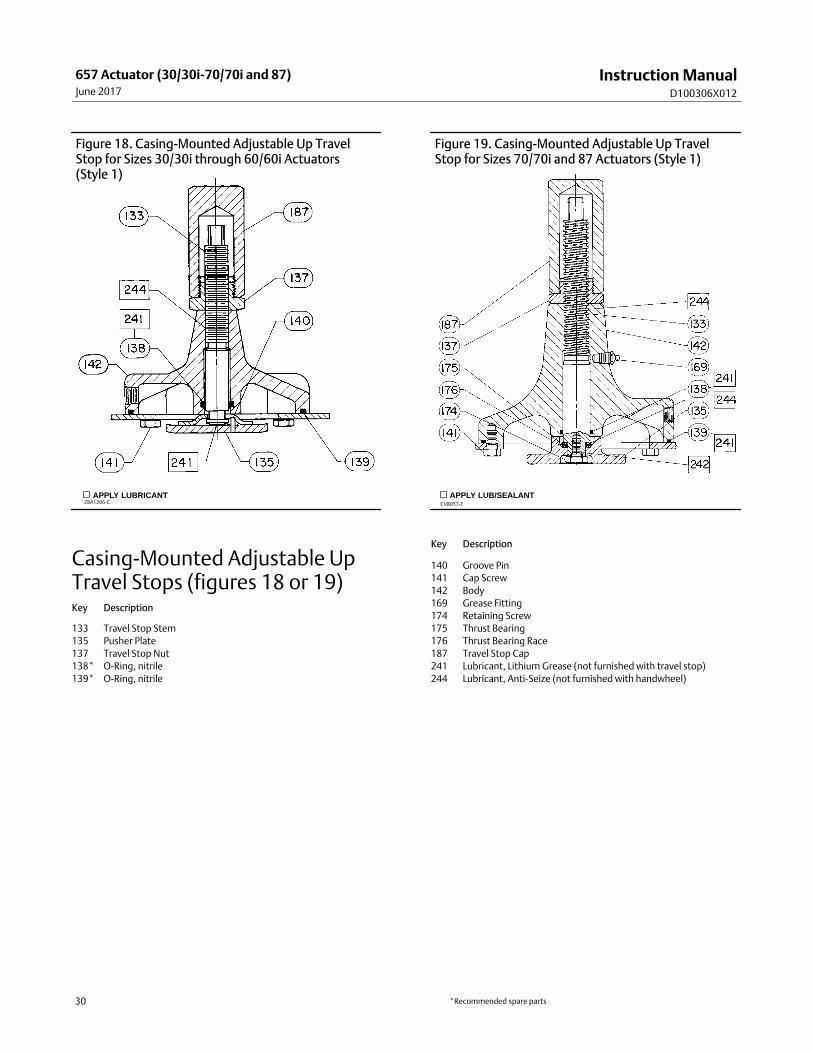
The casing‐mounted adjustable up travel stop (figures 18 or 19) limits the actuator stroke in the upward direction. Toadjust, first relieve actuator loading pressure before removing the travel stop cap (key 187, figure 18 or 19). Loosenthe travel stop nut (key 137). Then turn the travel stop stem (key 133) clockwise into the diaphragm case to move theactuator stem downward (or counter‐clockwise to move the stem upward). Finally, tighten the travel stop nut andreplace the travel stop cap.
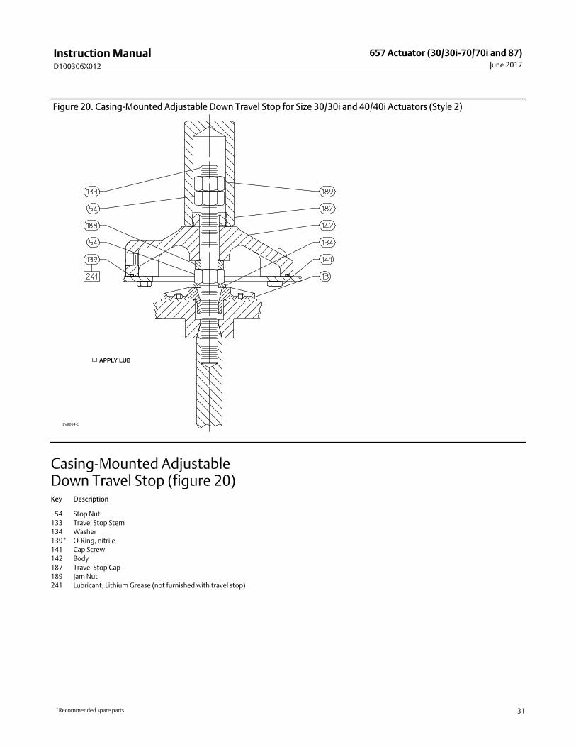
The adjustable down travel stop (figure 20) limits the actuator stroke in the downward direction. To adjust, first relieveactuator loading pressure before removing the travel stop cap (key 187). Then loosen the jam nut and adjust the stopnut (keys 189 and 54) either down on the stem to limit travel, or up on the stem to allow more travel. Lock the jam nutagainst the stop nut, then replace the closing cap.
Instructions are given below for disassembly and assembly. Perform the disassembly only as far as necessary toaccomplish the required maintenance; then, begin the assembly at the appropriate step.
Key numbers are shown in figures 18, 19, and 20.
Instruction ManualD100306X012
657 Actuator (30/30i-70/70i and 87)June 2017
20
Disassembly for Casing‐Mounted Travel Stop
Bypass the control valve. Reduce the loading pressure to atmospheric, and remove the tubing or piping from theconnection in the body (key 142).
Casing‐Mounted Adjustable Up Travel Stops
WARNING
To avoid personal injury from the precompressed spring force thrusting the upper diaphragm casing (key 1) away from theactuator, relieve spring compression (steps 1 and 2, below), and carefully remove casing cap screws (key 22) (step 3, below).
1. Thread the spring adjuster (key 12) out of the yoke (key 9) until all spring compression is relieved.
2. Remove the travel stop cap (key 187) and loosen the travel stop nut (key 137). Rotate the travel stop stem (key 133) counter‐clockwise until the travel stop assembly is no longer compressing the spring.
3. Remove the upper diaphragm casing (key 1, figures 6, 7, 8, 9, or 10) as outlined in the Maintenance section.
4. Remove the cap screws (keys 141) and separate the travel stop assembly from the upper casing.
5. Remove and inspect the O‐rings (keys 138 and 139); replace if necessary.
6. Proceed with the following procedure, based on actuator size:
� For sizes 30/30i through 60/60i, drive out the groove pin (key 140), and slide the pusher plate (key 135) off thetravel stop stem (key 133) or....
� For sizes 70/70i and 87, remove the retaining screw (key 174) to inspect the thrust bearing (key 175).
Casing‐Mounted Adjustable Down Travel Stops
WARNING
To avoid personal injury from the precompressed spring force thrusting the upper diaphragm casing (key 1) away from theactuator, relieve spring compression (steps 1 and 2, below), and carefully remove casing cap screws (key 22) (step 3, below).
1. Thread the spring adjuster (key 12) out of the yoke (key 9) until all spring compression is relieved.
2. Remove the travel stop cap (key 187). Unscrew the jam nut and stop nut (keys 189 and 54) until the travel stopassembly is no longer compressing the spring. Remove the jam nut and stop nut.
3. Remove the upper diaphragm casing (key 1, figures 6, 7, 8, 9, or 10) as outlined in the Maintenance section.
4. Remove the cap screws (keys 141) and separate the travel stop assembly from the upper casing.
5. Remove and inspect the O‐ring (keys 139); replace if necessary.
6. For all actuator sizes: Loosen the stop nut (key 54), then unscrew the travel stop stem (key 133) out of the actuatorstem. The lower diaphragm plate can now be removed.
Assembly for Casing‐Mounted Travel Stop1. Reassemble the up or down travel stop in the reverse order of the disassembly steps, being sure to apply lubricant
as shown by the lubrication boxes (key 241) in figures 6, 7, 8, 9, 10, 18, 19, or 20, as appropriate.
2. Readjust the travel stop to obtain the appropriate restriction by following the adjustment procedures presented inthe introductory portion of the Casing‐Mounted Adjustable Travel Stops section. Return the unit to operation.
Instruction ManualD100306X012
657 Actuator (30/30i-70/70i and 87)June 2017
21
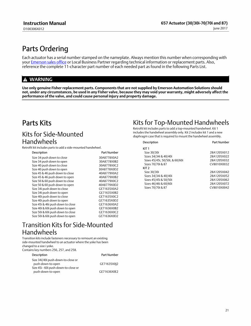
Parts OrderingEach actuator has a serial number stamped on the nameplate. Always mention this number when corresponding withyour Emerson sales office or Local Business Partner regarding technical information or replacement parts. Also,reference the complete 11‐character part number of each needed part as found in the following Parts List.
WARNING
Use only genuine Fisher replacement parts. Components that are not supplied by Emerson Automation Solutions shouldnot, under any circumstances, be used in any Fisher valve, because they may void your warranty, might adversely affect theperformance of the valve, and could cause personal injury and property damage.
Parts Kits
Kits for Side‐MountedHandwheelsRetrofit kit includes parts to add a side‐mounted handwheel.
Description Part Number
Size 34 push down to close 30A8778X0A2
Size 34 push down to open 30A8778X0B2
Size 40 push down to close 30A8778X0C2
Size 40 push down to open 30A8778X0D2
Size 45 & 46 push down to close 40A8779X0A2
Size 45 & 46 push down to open 40A8779X0B2
Size 50 & 60 push down to close 40A8779X0C2
Size 50 & 60 push down to open 40A8779X0D2
Size 34i push down to close GE71635X0A2
Size 34i push down to open GE71635X0B2
Size 40i push down to close GE71635X0C2
Size 40i push down to open GE71635X0D2
Size 45i & 46i push down to close GE71636X0A2
Size 40i & 60i push down to open GE71636X0B2
Size 50i & 60i push down to close GE71636X0C2
Size 50i & 60i push down to open GE71636X0D2
Transition Kits for Side‐MountedHandwheelsTransition kits include fasteners necessary to remount an existing
side-mounted handwheel to an actuator where the yoke has been
changed to a size i yoke.
Contains key numbers 256, 257, and 258.
Description Part Number
Size 34i/40i push-down-to-close or
push-down-to-open GE71635X0J2
Size 45i - 60i push-down-to-close or
push-down-to-open GE71636X0E2
Kits for Top‐Mounted HandwheelsRetrofit kit includes parts to add a top‐mounted handwheel. Kit 1
includes the handwheel assembly only. Kit 2 includes kit 1 and a new
diaphragm case that is required to mount the handwheel assembly.
Description Part Number
KIT 1
Size 30/30i 28A1205X012
Sizes 34/34i & 40/40i 28A1205X022
Sizes 45/45i, 50/50i, & 60/60i 28A1205X032
Sizes 70/70i & 87 CV8010X0032
KIT 2
Size 30/30i 28A1205X042
Sizes 34/34i & 40/40i 28A1205X052
Sizes 45/45i & 50/50i 28A1205X062
Sizes 46/46i & 60/60i 28A1205X072
Sizes 70/70i & 87 CV8010X0042
Instruction ManualD100306X012
657 Actuator (30/30i-70/70i and 87)June 2017
22
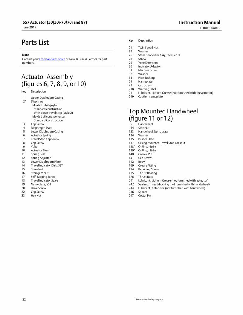
Parts List
Note
Contact your Emerson sales office or Local Business Partner for part
numbers.
Actuator Assembly (figures 6, 7, 8, 9, or 10)Key Description
�1 Upper Diaphragm Casing
�2* Diaphragm
Molded nitrile/nylon
Standard construction
With down travel stop (style 2)
Molded silicone/polyester
Standard Construction
�3 Cap Screw
�4 Diaphragm Plate
�5 Lower Diaphragm Casing
�6 Actuator Spring
�7 Travel Stop Cap Screw
�8 Cap Screw
�9 Yoke
10 Actuator Stem
11 Spring Seat
12 Spring Adjuster
13 Lower Diaphragm Plate
14 Travel Indicator Disk, SST
15 Stem Nut
16 Stem Jam Nut
17 Self‐Tapping Screw
18 Travel Indicator Scale
19 Nameplate, SST
20 Drive Screw
22 Cap Screw
23 Hex Nut
Key Description
24 Twin Speed Nut
25 Washer
26 Stem Connector Assy, Steel Zn Pl
28 Screw
29 Yoke Extension
30 Indicator Adaptor
31 Machine Screw
32 Washer
33 Pipe Bushing
61 Nameplate
73 Cap Screw
238 Warning label
241 Lubricant, Lithium Grease (not furnished with the actuator)
249 Caution nameplate
Top Mounted Handwheel (figure 11 or 12)�51 Handwheel
�54 Stop Nut
133 Handwheel Stem, brass
134 Washer
135 Pusher Plate
137 Casing‐Mounted Travel Stop Locknut
138* O‐Ring, nitrile
139* O‐Ring, nitrile
140 Groove Pin
141 Cap Screw
142 Body
169 Grease Fitting
174 Retaining Screw
175 Thrust Bearing
176 Thrust Race
241 Lubricant, Lithium Grease (not furnished with actuator)
242 Sealant, Thread‐Locking (not furnished with handwheel)
244 Lubricant, Anti‐Seize (not furnished with handwheel)
246 Spacer
247 Cotter Pin
*Recommended spare parts
Instruction ManualD100306X012
657 Actuator (30/30i-70/70i and 87)June 2017
23
Figure 6. Fisher 657 Actuator Sizes 30 through 60
APPLY LUB
40A8765-C
Figure 7. Fisher 657 Actuator Sizes 30i through 60i
APPLY LUB
GE71419-APARTS NOT SHOWN: KEY 7, 24, AND 249
Instruction ManualD100306X012
657 Actuator (30/30i-70/70i and 87)June 2017
24
Figure 8. Fisher 657 Size 70 Actuator
APPLY LUB
50A8768-C
Figure 9. Fisher 657 Size 70i Actuator
APPLY LUB
GE71634-A
PARTS NOT SHOWN: KEY 7, 24, AND 249
Instruction ManualD100306X012
657 Actuator (30/30i-70/70i and 87)June 2017
25
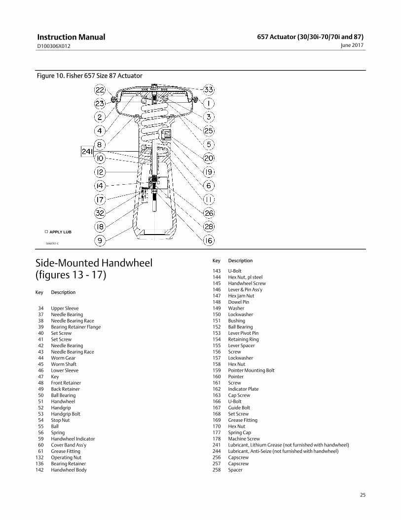
Figure 10. Fisher 657 Size 87 Actuator
APPLY LUB
50A8767-C
Side‐Mounted Handwheel(figures 13 - 17)
Key Description
�34 Upper Sleeve
�37 Needle Bearing
�38 Needle Bearing Race
�39 Bearing Retainer Flange
�40 Set Screw
�41 Set Screw
�42 Needle Bearing
�43 Needle Bearing Race
�44 Worm Gear
�45 Worm Shaft
�46 Lower Sleeve
�47 Key
�48 Front Retainer
�49 Back Retainer
�50 Ball Bearing
�51 Handwheel
�52 Handgrip
�53 Handgrip Bolt
�54 Stop Nut
�55 Ball
�56 Spring
�59 Handwheel Indicator
�60 Cover Band Ass'y
�61 Grease Fitting
132 Operating Nut
136 Bearing Retainer
142 Handwheel Body
Key Description
143 U‐Bolt
144 Hex Nut, pl steel
145 Handwheel Screw
146 Lever & Pin Ass'y
147 Hex Jam Nut
148 Dowel Pin
149 Washer
150 Lockwasher
151 Bushing
152 Ball Bearing
153 Lever Pivot Pin
154 Retaining Ring
155 Lever Spacer
156 Screw
157 Lockwasher
158 Hex Nut
159 Pointer Mounting Bolt
160 Pointer
161 Screw
162 Indicator Plate
163 Cap Screw
166 U-Bolt
167 Guide Bolt
168 Set Screw
169 Grease Fitting
170 Hex Nut
177 Spring Cap
178 Machine Screw
241 Lubricant, Lithium Grease (not furnished with handwheel)
244 Lubricant, Anti‐Seize (not furnished with handwheel)
256 Capscrew
257 Capscrew
258 Spacer
Instruction ManualD100306X012
657 Actuator (30/30i-70/70i and 87)June 2017
26
Figure 11. Top‐Mounted Handwheel Assembly forSize 30/30i through 60/60i Actuators
APPLY LUB/SEALANT
NOTES:THE TOP MOUNTED HANDWHEEL IS NOT DESIGNED FOR USE UNDER HEAVY LOADOR FOR FREQUENT USE.
28A1205‐D
Figure 12. Top‐Mounted Handwheel Assembly forSizes 70/70i through 87 Actuators
APPLY LUB/SEALANTNOTES:THE TOP MOUNTED HANDWHEEL IS NOT DESIGNED FOR USE UNDERHEAVY LOAD OR FOR FREQUENT USE.
CV8010‐G
Instruction ManualD100306X012
657 Actuator (30/30i-70/70i and 87)June 2017
27
Figure 13. Side‐Mounted Handwheel Assembly for Size 34 and 40 Actuators
APPLY LUBRICANT30A8778‐D
Figure 14. Side‐Mounted Handwheel Assembly for Size 34i and 40i Actuators
APPLY LUBRICANTGE71635-A
PARTS NOT SHOWN: KEY 157, 158, 159, AND 168
Instruction ManualD100306X012
657 Actuator (30/30i-70/70i and 87)June 2017
28
Figure 15. Side‐Mounted Handwheel Assembly for Size 45, 46, 50, and 60 Actuators
APPLY LUBRICANT40A8779‐D
Figure 16. Side‐Mounted Handwheel Assembly for Size 45i, 46i, 50i, and 60i Actuators
APPLY LUBRICANTGE71636‐A PARTS NOT SHOWN: KEY 158, 159, AND 168
Instruction ManualD100306X012
657 Actuator (30/30i-70/70i and 87)June 2017
29
Figure 17. Fisher 657 Size 70 and 87 Actuators with Side‐Mounted Handwheel
APPLY LUB
50A8769-D
SECTION A-A
Instruction ManualD100306X012
657 Actuator (30/30i-70/70i and 87)June 2017
30
Figure 18. Casing‐Mounted Adjustable Up TravelStop for Sizes 30/30i through 60/60i Actuators (Style 1)
28A1206‐C APPLY LUBRICANT
Casing‐Mounted Adjustable UpTravel Stops (figures 18 or 19)Key Description
133 Travel Stop Stem
135 Pusher Plate
137 Travel Stop Nut
138* O‐Ring, nitrile
139* O‐Ring, nitrile
Figure 19. Casing‐Mounted Adjustable Up TravelStop for Sizes 70/70i and 87 Actuators (Style 1)
APPLY LUB/SEALANTCV8057-E
Key Description
140 Groove Pin
141 Cap Screw
142 Body
169 Grease Fitting
174 Retaining Screw
175 Thrust Bearing
176 Thrust Bearing Race
187 Travel Stop Cap
241 Lubricant, Lithium Grease (not furnished with travel stop)
244 Lubricant, Anti‐Seize (not furnished with handwheel)
*Recommended spare parts
Instruction ManualD100306X012
657 Actuator (30/30i-70/70i and 87)June 2017
31
Figure 20. Casing‐Mounted Adjustable Down Travel Stop for Size 30/30i and 40/40i Actuators (Style 2)
APPLY LUB
BV8054-E
Casing‐Mounted AdjustableDown Travel Stop (figure 20)Key Description
�54 Stop Nut
133 Travel Stop Stem
134 Washer
139* O‐Ring, nitrile
141 Cap Screw
142 Body
187 Travel Stop Cap
189 Jam Nut
241 Lubricant, Lithium Grease (not furnished with travel stop)
*Recommended spare parts

Instruction ManualD100306X012
657 Actuator (30/30i-70/70i and 87)June 2017
32
www.Fisher.com
The contents of this publication are presented for informational purposes only, and while every effort has been made to ensure their accuracy, they are notto be construed as warranties or guarantees, express or implied, regarding the products or services described herein or their use or applicability. All sales aregoverned by our terms and conditions, which are available upon request. We reserve the right to modify or improve the designs or specifications of suchproducts at any time without notice.
� 1983, 2017 Fisher Controls International LLC. All rights reserved.
Fisher, easy-e, and FIELDVUE are marks owned by one of the companies in the Emerson Automation Solutions business unit of Emerson Electric Co. EmersonAutomation Solutions, Emerson, and the Emerson logo are trademarks and service marks of Emerson Electric Co. All other marks are the property of theirrespective owners.
Neither Emerson, Emerson Automation Solutions, nor any of their affiliated entities assumes responsibility for the selection, use or maintenanceof any product. Responsibility for proper selection, use, and maintenance of any product remains solely with the purchaser and end user.
Emerson Automation SolutionsMarshalltown, Iowa 50158 USASorocaba, 18087 BrazilCernay, 68700 FranceDubai, United Arab EmiratesSingapore 128461 Singapore