fish passage planning and design - jcu.edu.au · fish passage planning and design . ... the...
TRANSCRIPT
Culvert Fishway Planning and Design GuidelinesPart H – Rock Ramp Fishways for Open Channels
Ross Kapitzke James Cook University School of Engineering and Physical Sciences
April 2010 – VER2.0
Fish Passage Planning and Design

VER2.0 -/04/10
School of Engineering and Physical Sciences • Ross Kapitzke • fishways\H_rock ramp fishways for open channels -/4/10 H-i
Culvert fishway guidelines: Part H – Rock ramp fishways for open channels
James Cook University School of Engineering and Physical Sciences Culvert Fishway Planning and Design Guidelines Part H – Rock Ramp Fishways for Open Channels Contents
1 INTRODUCTION 1
2 FISH MIGRATION BARRIER PROBLEMS IN OPEN CHANNELS 2
3 GENERAL ASPECTS OF ROCK RAMP FISHWAYS 5 3.1 Design concept and method of operation 5 3.2 Full width and partial width fishways 6 3.3 Random rock and ridge rock designs 6
4 ROCK RAMP FISHWAY DESIGN CHARACTERISTICS 8 4.1 Design configuration of rock ramp fishway 9 4.2 Design configuration of rock ramp cascade fishway 11 4.3 Structure and foundation characteristics for rock ramp fishways 12 4.4 Hydraulic performance characteristics of rock ramp fishways 15 4.5 Fish passage, conveyance, sediment and maintenance characteristics of rock ramps 16
5 ROCK RAMP FISHWAY CONSTRUCTION ASPECTS 19
6 OVERALL SUITABILITY OF ROCK RAMP FISHWAY DESIGNS 21
7 BIBLIOGRAPHY 22
APPENDIX H1 – DOUGLAS ARTERIAL ROAD PROTOTYPE ROCK RAMP FISHWAY 1
APPENDIX H2 – SOLANDER ROAD PROTOTYPE ROCK RAMP CASCADE FISHWAY 2

VER2.0 -/04/10
School of Engineering and Physical Sciences • Ross Kapitzke • fishways\H_rock ramp fishways for open channels -/4/10 H-1
Culvert fishway guidelines: Part H – Rock ramp fishways for open channels
James Cook University School of Engineering and Physical Sciences Culvert Fishway Planning and Design Guidelines Part H – Rock Ramp Fishways for Open Channels
1 INTRODUCTION
Where provisions for fish passage are to be made in steep grade open channel sections downstream of culverts, in diversion drains, or at waterway structure inlets and outlets, designers, managers and scientists require information on design options for fishway facilities, and the configuration and performance characteristics of fish passage devices such as rock ramps that meet fish passage as well as grade control and channel design requirements.
These Guidelines Part H present the rock ramp fishway designs for open channels, and aim to:
identify rock ramp fishway design options to suit particular hydraulic barriers to fish passage in open channels, and describe relevant fishway configurations and characteristics
outline design concepts and background, configurations, construction aspects and performance characteristics for rock ramp fishways
illustrate rock ramp fishway design for open channels through the Douglas Arterial Road and Solander Road case study projects on University Creek
summarise findings of the field prototype rock ramp and rock ramp cascade fishway designs (Appendix H1; Appendix H2)
The information from Guidelines Part H is used in other parts of these Guidelines to:
guide the selection of fishway devices to meet fish passage requirements for open channels (Part C – Fish Migration Barriers and Fish Passage Options for Road Crossings)
guide the design configurations for fishway facilities in waterways incorporating rock ramp fishways (Part E – Fish Passage Design: Site Scale)
These Guidelines deal primarily with the Concept and Preliminary Design phases of planning and design procedures for road and other infrastructure projects. They apply to design of fish passage facilities to mitigate potential fish migration barrier impacts for new structures, and also to remediation measures to overcome migration barriers by retrofit at existing structures (Box H1.1). The focus is on free standing rock ramp fishways for open channel situations, but similar approaches apply for attached ramp fishway structures at road culverts, barrier walls and steep grades or drops at inlets and outlets to other waterway structures. These ramp fishway facilities (in particular attached ramps at waterway structures) may incorporate alternatives to rock, such as prefabricated fishway blocks within prefabricated or cast-in-place fishway channel sections.
Box H1.1: Rock ramp fishways established at the Douglas Arterial Project and Solander Road crossings of University Creek in Townsville (Source: Ross Kapitzke)
Douglas Arterial Project rock ramp fishway within open channel diversion drain at bridge
site (25/01/05)
Solander Road rock ramp cascade fishway downstream of pipe culvert / causeway
(09/04/06)
VER2.0 -/04/10
School of Engineering and Physical Sciences • Ross Kapitzke • fishways\H_rock ramp fishways for open channels -/4/10 H-2
Culvert fishway guidelines: Part H – Rock ramp fishways for open channels
2 FISH MIGRATION BARRIER PROBLEMS IN OPEN CHANNELS
Natural waterways have channel features such as stream meandering, pools and riffles, vegetation, boulders and other substrate and in-channel form that provide diverse patterns of flow and a range of hydraulic conditions, which with the exception of rapids and large waterfalls, are inherently suited to upstream fish passage for native fish species in the stream. Artificial channels formed by channelisation, realignment, or bed and bank lining usually simplify channel form, modify flow patterns, and reduce hydraulic diversity to create adverse conditions for fish movement in the waterway (e.g. velocity, turbulence, water depth).
Water surface drops commonly result from channel erosion and lowering of bed levels in artificial channels and at culvert outlets, and from steep channels or drops at the inlets and outlets to other waterway structures. These drops and are often associated with grade control structures that are incorporated into channel designs to mitigate erosion effects associated with waterway modification, or as remediation of degraded channel sections. Hydraulic conditions are commonly more severe at the erosion heads, degraded channel sections and grade control structures than at rifles and other natural channel sections, and the associated water surface drops and high velocity shallow flows often represent barriers to upstream fish movement.
Rock ramp fishways can be used to overcome fish migration barriers in degraded open channels and at grade control structures, in lieu of conventional waterway design, which is focused on drainage and utility functions. The rock ramp fishways can also be used in association with other fishway components to overcome barriers at road culverts and other waterway structures, including implementation in downstream channel sections to raise water levels at the culvert outlet. This chapter briefly outlines common fish migration barrier problems for these situations, and introduces the Douglas Arterial Road and Solander Road case study projects on University Creek (Box H2.1), where prototype rock ramp and rock ramp cascade fishway designs have been implemented (Kapitzke 2006c; Kapitzke 2007c). Information on development and testing of these prototype fishways is included here in Appendix H1 – Douglas Arterial Road Prototype Rock Ramp Fishway and Appendix H2 – Solander Road Prototype Rock Ramp Cascade Fishway.
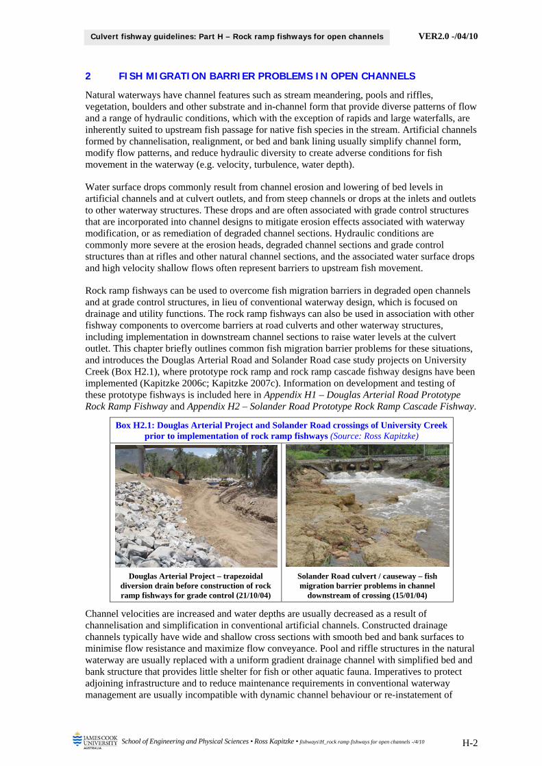
Box H2.1: Douglas Arterial Project and Solander Road crossings of University Creek prior to implementation of rock ramp fishways (Source: Ross Kapitzke)
Douglas Arterial Project – trapezoidal diversion drain before construction of rock ramp fishways for grade control (21/10/04)
Solander Road culvert / causeway – fish migration barrier problems in channel
downstream of crossing (15/01/04)
Channel velocities are increased and water depths are usually decreased as a result of channelisation and simplification in conventional artificial channels. Constructed drainage channels typically have wide and shallow cross sections with smooth bed and bank surfaces to minimise flow resistance and maximize flow conveyance. Pool and riffle structures in the natural waterway are usually replaced with a uniform gradient drainage channel with simplified bed and bank structure that provides little shelter for fish or other aquatic fauna. Imperatives to protect adjoining infrastructure and to reduce maintenance requirements in conventional waterway management are usually incompatible with dynamic channel behaviour or re-instatement of
VER2.0 -/04/10
School of Engineering and Physical Sciences • Ross Kapitzke • fishways\H_rock ramp fishways for open channels -/4/10 H-3
Culvert fishway guidelines: Part H – Rock ramp fishways for open channels
natural channel features, thereby providing little opportunity for re-establishment of favourable hydraulic conditions for fish passage in these waterways without stream rehabilitation works such as rock ramps, pools and habitat structures to support natural stream geomorphic processes and to introduce hydraulic diversity in the channel.
Channel erosion and degradation downstream of culvert outlets commonly cause water surface drops and increase stream velocities and turbulence levels, which in turn tend to increase stream erosion and worsen the hydraulic barrier effects on fish passage at the crossing and in the stream channel downstream. Steep channel sections and drops at waterway structure inlets and outlets and conventional grade control structures (e.g. concrete weirs or dumped rock) may be used to abruptly vary stream bed levels and to localise energy dissipation and erosion at these sites. These grade control features and degraded stream reaches commonly produce adverse hydraulic conditions for fish passage due to excessive water surface drops, high velocities and turbulence, lack of resting place or shelter, and shallow water depths at the structures.
For example, the initial diversion drain design for the Douglas Arterial Road crossing of University Creek had typical fish migration barrier problems associated with an artificial drainage channel until rock ramp fishway designs where incorporated into grade control structures for a modified drainage design at the site (Box H2.2). Rock ramp cascade grade control structures were incorporated into the downstream channel at the Solander Road pipe culvert / causeway crossing of University Creek to address adverse hydraulic conditions for fish associated with stream degradation and lowering of tailwater levels at the site (Box H2.3).
The common types of hydraulic barriers to upstream fish movement within various steep open channel components and drops at waterway structure are listed below. This is illustrated in Box H2.2, which shows fish migration barriers for the Douglas Arterial Road crossing of University Creek, where the rock ramp fishways were incorporated as mitigation measures within the diversion drain (Kapitzke 2006c). Examples are also provided in Box H2.3, which shows the various hydraulic zones and fish migration barriers for the Solander Road culvert crossing, where the rock ramp cascades were implemented as remediation measures in the downstream channel section (Kapitzke 2007c). Whereas the focus of these Guidelines Part H is on free standing rock ramp fishways at open channel sections, the principles also generally apply to attached ramp fishway facilities at culverts, grade control and other waterway structures.
Open channel / structure component Common barrier effect for fish movement
Channelised waterways and drainage channels
High velocities, shallow water depth, lack of resting place or shelter
Culvert outlet channels and other degraded waterways
High velocities, excess turbulence, water surface drop
Conventional grade control structures, drops and steep channel sections
High velocities, shallow water depth, lack of resting place or shelter, excess turbulence, water surface drop

VER2.0 -/04/10
School of Engineering and Physical Sciences • Ross Kapitzke • fishways\H_rock ramp fishways for open channels -/4/10 H-4
Culvert fishway guidelines: Part H – Rock ramp fishways for open channels
Box H2.2: Diversion drain design and fish migration barrier effects within Douglas Arterial Road crossing (After: Kapitzke 2006c)
Initial diversion drain proposal – potential fish barrier effects prior to mitigation
increased velocities due to a steepened channel section with simplified cross section and hard rock lining
streamlined flow and lack of resting places due to reduction in hydraulic diversity and channel complexity through channel simplification
shallower flow due to the wide stream section
(Photo: 21/10/04; Source: Ross Kapitzke)
Box H2.3: Hydraulic zones and fish migration barriers within downstream channel zone of Solander Road pipe culvert crossing (After: Kapitzke 2007c)
Zone A: Downstream channel and apron drop-off – fish migration barriers prior to remediation
turbulent, high velocity flow in parts of downstream channel at low flows
water surface drop, plunging jet and turbulence at end apron at low flows
turbulent, high velocity flow in downstream channel at medium flows
water surface drop and hydraulic jump downstream of the apron
(Photo: 15/01/04; Source: Ross Kapitzke)
Culvert inlet and upstream channel
Culvert barrel
Downstream channel and apron drop-off Culvert outlet and apron slab
Zone D Zone C Zone B Zone A
4–Barrel pipe culvert, causeway and apron
Flow
Low flow Medium flow
1200
1400
1350
1300
1250
N
Discovery Drive – Eastern Access Road
to Townsville
University Road – Bruce Highway
to James Cook University
to Ayr
to Condon
Douglas Arterial Ring Road
The Townsville Hospital
University Creek
Flow
Legend
1300 Stream distance upstream from Ross River (m)
Sewer line
Drain
Diversion drain and rock ramp fishways see detail plans
4-span, 2-lane bridge
Initial diversion drain proposal

VER2.0 -/04/10
School of Engineering and Physical Sciences • Ross Kapitzke • fishways\H_rock ramp fishways for open channels -/4/10 H-5
Culvert fishway guidelines: Part H – Rock ramp fishways for open channels
3 GENERAL ASPECTS OF ROCK RAMP FISHWAYS
Rock ramps are nature-like fishways providing fish passage and aquatic habitat in a stream through simulation of the natural stream environment of riffles, pools and rapids. Developed as an alternative to formal fishway structures for low water level drops, the rock ramp fishways now have widespread application where upstream fish passage is required at low level weirs, at grade control structures in open channels, and in channel sections downstream of road culverts subject to large water surface drops. Although relatively informal structures, rock ramps fishways must be carefully configured and rocks strategically placed to provide appropriate hydraulic conditions for fish to overcome barriers at the site and to pass upstream.
The following sections discuss design concepts and the method of operation for rock ramp fishways, and identify various design configurations and structure types. This provides general background information for using rock ramp fishways in waterway applications (see Chapter 4).
3.1 Design concept and method of operation
Based initially on designs for stream-bed control and habitat-restoration structures developed for Canadian streams by Newbury and Gadoury (1993) and in Europe, rock ramps are used either as fishways below low-level barriers such as weirs, or as dual-purpose fishways and grade control structures within a stream channel. Where incorporated in grade control structures, the rock ramps prevent headward erosion or knick-point progression in the stream bed, thereby limiting channel deepening, undercutting of banks, generation of sediment downstream, and infrastructure damage. For dams and weirs, rock ramp fishways constructed of natural materials (rock), are generally cheaper to build and maintain than more formal fishway structures (e.g. vertical slot), which are usually constructed in regular shapes from conventional materials such as concrete or metal. Construction techniques for rock ramps are simpler than some of the more complicated formal fishway structures, and local agency staff and contractors can often undertake the work (Thorncraft and Marsden 2000). For smaller drops and steep sections at culverts and other waterway structures, prefabricated ramp fishway structures may be suitable in lieu of rock ramps.
Rock ramps are low gradient structures, incorporating either transverse or randomly placed ridge rocks. These ridges comprise large boulders placed at strategic points to create a series of pools and riffles that mimic flow conditions in the natural stream and allow fish to move from pool to pool and over the rock weirs through zones of low flow velocities and turbulence (Box H3.1). The aim of the rock ramp and other nature-like fishways is to provide multiple interconnected pathways for fish passage using continuous swimming or a burst and rest swimming pattern (Katopodis et al. 2001). Unlike conventional dam and weir fishway structures, which commonly cater for target species at particular flow conditions, rock ramps and other nature-like fishways provide suitable passage and habitat for a variety of species over a range of flows, and are suited to the contemporary ecosystem view of fish and fish habitat management (Katopodis et al. 2001).
Box H3.1: Rock ramp fishways showing layout with rock ridges and flow paths
Bell River, NSW rock ramp fishway and grade control structure (Source: Thorncraft
and Harris 1997)
Reliance Creek, Mackay rock ramp fishway at road culvert – showing grouted rock channel (Source: Marsden et al. 2003)

VER2.0 -/04/10
School of Engineering and Physical Sciences • Ross Kapitzke • fishways\H_rock ramp fishways for open channels -/4/10 H-6
Culvert fishway guidelines: Part H – Rock ramp fishways for open channels
The irregular nature of the rock ramp fishway provides a range of alternative water velocities and depths to cater for differing behaviour of fish negotiating the barrier, with the larger stronger-swimming fish using the deeper, higher water velocity sections, and the smaller weaker-swimming fish using the shallower, lower water velocity sections (Thorncraft and Marsden 2000; O’Brien 1998). Australian fish cannot sustain long periods of swimming headlong into fast-flowing streams and most Australian fish cannot negotiate even small free-fall drops over low weirs (Harris and 0’Brien 1999). Water velocities should be appropriate to the swimming abilities of the species involved and the vertical drop at any point along the expected path for the fish must be carefully controlled.
3.2 Full width and partial width fishways
The rock ramp may be a full width structure occupying the full stream channel at bankfull flow or structure drown-out level, or a partial width structure occupying only a portion of the channel width (Box H3.2). Whereas partial width ramp fishway structures may be used downstream of weirs or other waterway structures, full width rock ramps are commonly used as free standing structures in open channel situations for road-waterway projects. Full-width rock ramps are the most desirable option for effective fish passage (Thorncraft and Marsden 2000). They are more stable than the alternative partial width ramp, allow fish to find the fishway entrance location with greater ease, and are more able to provide fish passage over a range of flows (0’Brien 1998).
Partial width rock ramps may be used at road culverts, causeways, grade control and other waterway structures, and are commonly associated with weirs. They are designed to occupy only a portion of the channel width, generally with a return leg to bring the entrance close to the weir wall. Partial width structures are used either because of the size and cost of the full width structure, or due to configuration difficulties associated with the site. The main problem with partial-width ramps is that the fishway may only work during low flows. Fish have trouble finding the fishway in higher flows (Thorncraft and Marsden 2000).
Box H3.2: Full width and partial width rock ramp fishways conceptual layout (Source: Thorncraft and Harris 2000)
Full width rock ramp fishway at weir Partial width rock ramp fishway at weir
3.3 Random rock and ridge rock designs
A number of alternative configurations of rocks within the fishway structure are used for rock ramp fishways in Australia. Designs have evolved along several paths in various parts of Australia, according to regional preferences and the prevailing disciplinary emphasis. Whereas a pool/riffle random rock design is commonly used in Victoria, a number of variations of a pool/weir ridge rock design are used in NSW and in Queensland (Box H3.3).
The random rock fishway simulates a natural rock rapid, and comprises boulders placed randomly along a constant slope ramp, with up to 50 % of the ramp surface comprising large boulders protruding above the ramp surface (O’Brien 1998). Small fish and macroinvertebrates ascend the fishway using voids between ridge, valley and side boulders. The hydraulic energy on
VER2.0 -/04/10
School of Engineering and Physical Sciences • Ross Kapitzke • fishways\H_rock ramp fishways for open channels -/4/10 H-7
Culvert fishway guidelines: Part H – Rock ramp fishways for open channels
the rock chute is reduced by the hydraulic roughness created by the random ridge type boulders, and the roughness provided by the valley and side boulders (Hader, n.d. - c).
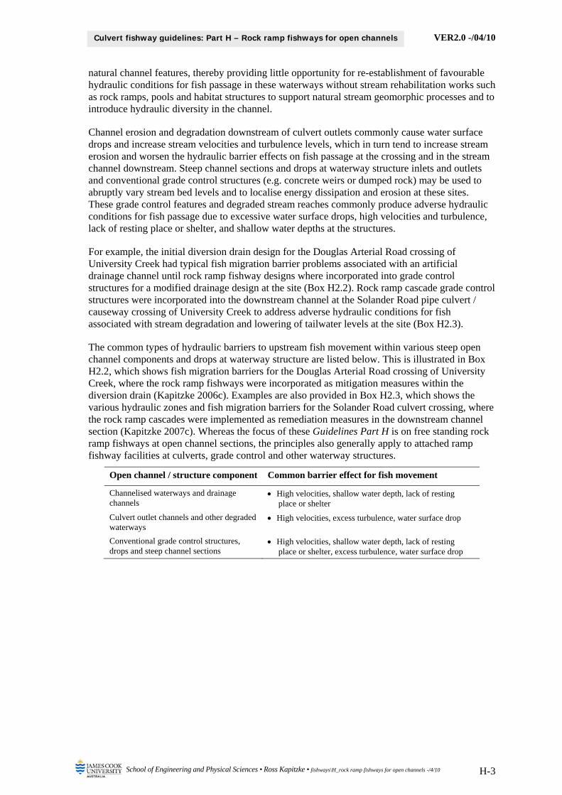
The low ridge rock weir type fishway is the preferred rock ramp design for Queensland streams. This fishway comprises a series of small pools and riffles that are arranged in a transverse stair-step configuration, with short steps at the riffles (formed by rock weirs comprising large ridge rocks) connecting slightly longer flat sections forming the pools. The ramp surface is formed into a series of ridges, which in the standard rock ramp design are placed at two metre intervals, with a 100 mm drop between ridges, giving an overall slope of 20:1 (Thorncraft and Marsden 2000). The streambed drop for individual ramp sections of structures such as these is usually set at a maximum of 1 m (Harris and 0’Brien 1999). A series of rock ramps can be linked by deep resting pools to cater for larger drops.
The transverse ridges in the rock ramps are located at right angles to the direction of flow, providing weir crests for flow down the ramp, and fixing the elevation of the bed at the desired level for the drain at that location (Box H3.4). Flow depth is relatively shallow at the riffle, and water velocities, although relatively high, are designed to comply with the burst range of fish speeds. Pools, which should have close to zero gradient, have slightly deeper and more tranquil flows, thereby providing resting places for fish passing upstream on the rock ramp fishway. The ridges are constructed so that weir/slots are formed in the gap between the ridge rocks. Hydraulic energy at low flows is reduced by weir overflow/slot through-flow. This fishway configuration creates controlled hydraulic conditions that can be matched with fish swimming characteristics.
Box H3.3: Random rock and ridge rock designs for rock ramp fishways
Darebin Creek, Melbourne rock ramp fishway and grade control structure –
random rock design (Source: Ross Kapitzke)
Port Hinchinbrook, Cardwell rock ramp fishway at weir – ridge rock design (Source:
Tim Marsden)
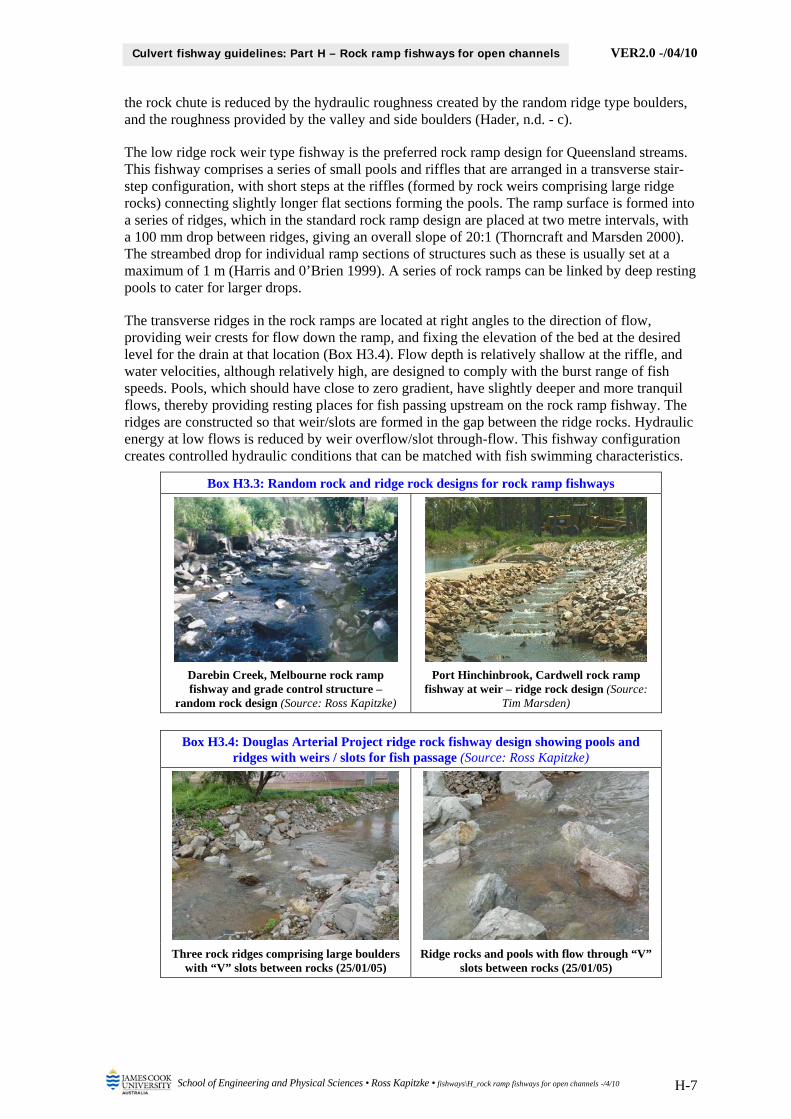
Box H3.4: Douglas Arterial Project ridge rock fishway design showing pools and
ridges with weirs / slots for fish passage (Source: Ross Kapitzke)
Three rock ridges comprising large boulders with “V” slots between rocks (25/01/05)
Ridge rocks and pools with flow through “V” slots between rocks (25/01/05)

VER2.0 -/04/10
School of Engineering and Physical Sciences • Ross Kapitzke • fishways\H_rock ramp fishways for open channels -/4/10 H-8
Culvert fishway guidelines: Part H – Rock ramp fishways for open channels
4 ROCK RAMP FISHWAY DESIGN CHARACTERISTICS
Rock ramp fishways can be used in open channel applications to overcome steep drops in the waterway bed, and in channel sections downstream of road culverts and other waterway structures to raise tailwater levels at the structure. Attached ramp fishway facilities at grade control and waterway structure inlets and outlets may use rock or prefabricated fishway components. In addition to providing for upstream fish passage, the ramp fishway provides a grade control function in the waterway and must be designed to meet multipurpose requirements for drainage, utility, fish passage and other environmental objectives.
The main applications for rock ramp fishways in road projects are as free standing structures in the stream channel, where they provide grade control as artificial riffle structures that facilitate upstream fish passage. Alternatively, rock ramps attached to the downstream side of waterway structures such as culverts, weirs or barrier walls provide a defined pathway configured for fish passage while also supporting the integrity of the structures in many instances. Other applications of rock ramp fishways at the inlet to culverts and other structures are intended to overcome a steep upstream channel section or drop in water level leading into the structure. Whereas free standing rock ramps in stream channels are typically full width designs, rock ramps attached to culverts and other waterway structures may be full or partial width designs.
The following sections outline design configurations and construction aspects for the rock ramp and rock ramp cascade fishways, and describe performance characteristics for the fishways. The focus is on free standing full width structures in open channel sections that are used to provide localised water level drops or to build up tailwater levels downstream of culvert outlets. The same principles on configuration of the rock ramp structure for fish passage will apply where a full width or partial width fishway is attached to a culvert or other barrier structure, although the requirements for stability and structural integrity will differ for the attached structure. Rock ramp fishways for weirs, although having many similarities to these designs, are not discussed here.
These provisions are illustrated by reference to the prototype rock ramp fishway installed in the diversion drain for the Douglas Arterial Road crossing of University Creek in Townsville (Box H4.1; Kapitzke 2006c), and the prototype rock ramp cascade fishway installed downstream of the Solander Road culvert crossing of University Creek (Box H4.1; Kapitzke 2007c). The hydraulic performance characteristics for the rock ramp and rock ramp cascade fishways incorporate material presented in the attached Appendix H1 – Douglas Arterial Road Prototype Rock Ramp Fishway and Appendix H2 – Solander Road Prototype Rock Ramp Cascade Fishway. The overall suitability and performance characteristics for the rock ramp and rock ramp cascade fishways are summarised in Chapter 5, along with suggestions for further development and testing of the rock ramp fishway design.
Box H4.1: University Creek prototype rock ramp fishways (Source: Ross Kapitzke)
Douglas Arterial Project rock ramp fishway – looking downstream during construction of
rock ridge and apron (21/10/04)
Solander Road rock ramp cascade fishway – looking upstream to rock ridge / cascades # 1
and #2 after construction (17/12/05)

VER2.0 -/04/10
School of Engineering and Physical Sciences • Ross Kapitzke • fishways\H_rock ramp fishways for open channels -/4/10 H-9
Culvert fishway guidelines: Part H – Rock ramp fishways for open channels
4.1 Design configuration of rock ramp fishway
The rock ramp structure comprises a series of transverse rock ridges, with short pool sections between the ridges to create a series of miniature pools and riffles to mimic natural flow conditions in the stream. The standard rock ramp fishway used for open channel applications comprises a series of ridges at 2 metre intervals, with a 100 mm drop between ridges and an overall longitudinal slope of 1 in 20 (Box H4.2). Ridge rocks of select size and shape are configured in a closely-abutting fashion along the ridge to form V-shaped gaps through which flow spills into shallow pools between the ridges. The V-slots provide controlled hydraulic conditions across the ridge crest and between adjoining ridges and pools. The bottom of the V represents the nominal crest level of the rock ridge, the top of the ridge rocks protrude 200-300 mm above the crest line, and the apron rocks within the intermediate pools are nominally 200-300 mm lower than the ridge crest at the upstream end of the pool adjacent to the ridge.
Box H4.2: Douglas Arterial Project prototype rock ramp fishway (Source: Kapitzke 2006c)
Rock ramp fishway configuration and details
Rock ramp fishway sections
In order to concentrate flow in the centre of the stream, the rock ramp commonly has a V-shaped section across the channel, with a cross slope of about 1 in 15 for the base of the ramp. This gives
A
Apron rock
Rock protection to drain bank
Toe wall
Ridge rock
Ridge
Pool
Drain batter
Flow
** 300 mm drop between upstream and downstream drain bed levels (3 x 100 mm
drops at ridges) **
Section A-A
Ridge rock 800 – 1000 mm nominal size refer detail
B CD
GeofabricLow flow
Apron rock 400 – 600 mm nominal size 2000 2000 2000 3000
200 100
Apron sill level
Apron sill level
Drain bed / ridge
crest level * Drain bed level *
Geofabric strip U/S rock ridge
Flow
Rock Ramp Plan
Ridge rock 800 – 1000 mm nominal size
Geofabric Gravel fill
Low flow
200 - 300
Nominal crest level of ridge
Detail – Ridge Rock
Geofabric
200 mm taper to drain centre over half drain width
Drain bed profile at apron
see Ridge rock detail
200 - 300
Nominal crest level of ridge
Geofabric
Apron rock 400 – 600 mm nominal size
Apron sill level
Nominal crest level of ridge
200 at drain centre downstream of ridge
Section B-B – Ridge
Section C-C – Apron within pool

VER2.0 -/04/10
School of Engineering and Physical Sciences • Ross Kapitzke • fishways\H_rock ramp fishways for open channels -/4/10 H-10
Culvert fishway guidelines: Part H – Rock ramp fishways for open channels
a fall of 200 mm from the edge of the channel bed to the centre of the structure for a 6 m wide channel (e.g. Douglas Arterial Project). The ridge and apron configuration should extend up the side of the channel cross section so that the ridge rock is anchored into the channel bank and so that the fishway function is maintained up to the design flow depth for fish passage through the structure (commonly 1.5 m above the stream bed). The ridge rocks are constructed in a single layer of large rocks, whereas the apron rock is constructed in riprap typically 2 – 3 layers thick. Geofabric is usually provided beneath the rock ramp and on the upstream face of the ridge rocks.
The rock ramp design used in the Douglas Arterial Road prototype fishway on University Creek in Townsville (Kapitzke 2006c) provides an example of the design configuration for a rock ramp fishway (Box H4.2). Two rock ramp fishway / grade control structures, each with a bed drop of 300 mm, are provided within a 6 m bed width diversion drain. Each rock ramp structure comprises 3 ridges with individual drops of 100 mm (see Appendix H1).
The general characteristics, configurations and design parameters for the rock ramp fishway for open channels that have been so far established from the literature, from the culvert fishway R & D program, and from conceptual design evaluation are presented in Box H4.3. This information should be used to guide the design and implementation of a rock ramp fishway facility at a field site. Actual design provisions and configuration requirements for the culvert fishway facility should be established on the basis of the site characteristics (see Guidelines Part E – Fish Passage Design: Site Scale).
Box H4.3: Characteristics, configurations and parameters for rock ramp fishway for open channels
Design aspect / parameter Performance characteristic, design consideration, comment and rationale
Rock ramp fishway configuration
Channel shape and planform the fishway is designed to look and function like a natural rapid, with a gentle slope similar to the natural stream to ensure appropriate fish passage conditions of depth, velocity and turbulence (Katopodis et al. 2001)
rock-ramp fishways cannot just be rock dumped in the stream but must be carefully configured and structured (Mallen-Cooper 1997)
Rock ramp slope, rock ridges and pools
overall slope for the standard rock ramp fishway is 1 in 20, with rock ridges at 2 m centres and 100 mm drop between ridge crests. Variations to standard designs may include steeper ramps (e.g. 1 in 15 with ridges at 1.5 m centres) and smaller drops (e.g. 50 mm or 75 mm) depending on site characteristics, fish community and fish movement requirements
ridge and pool spacing and drops should be consistent throughout, to avoid high water velocities and turbulence (Harris and 0’Brien 1999; Thorncraft and Marsden 2000)
Channel cross slope it may be possible to taper the fishway crest across the streambed using a V-shaped cross section that increases flow depth through the structure and improves fish passage at low flows (Harris and 0’Brien 1999; Thorncraft and Marsden 2000)
the Douglas Arterial Project rock ramps incorporate a cross fall of 200 mm from the edge of the channel bed to the centre of the structure (6 m bed width)
Extend ridge rocks up channel side
extend the ridge rock up the channel side to provide suitable hydraulic conditions for passage during high flow depths for surface-swimming species and other fish passing along the stream edge (Mallen-Cooper 1997)
the rock ridges and intermediate aprons for the Douglas Arterial Project rock ramps extend up the side of the fishway channel to a nominal depth of 1.5 m above the stream bed
Ridge rock, slot and pool configuration
provide V-shaped gaps between closely abutting ridge rocks, with the bottom of the V representing the nominal crest level of the rock ridge and the top of the ridge rocks protruding about 200-300 mm above the crest line
set apron rocks within the intermediate pools nominally 200-300 mm lower than the ridge crest at the upstream end of the pool adjacent to the ridge

VER2.0 -/04/10
School of Engineering and Physical Sciences • Ross Kapitzke • fishways\H_rock ramp fishways for open channels -/4/10 H-11
Culvert fishway guidelines: Part H – Rock ramp fishways for open channels
4.2 Design configuration of rock ramp cascade fishway
The rock ramp cascade fishway is an experimental design developed for application in stream reaches where a gradient steeper than 1 in 20 is required, and the standard rock ramp fishway would therefore not be appropriate. Each rock ramp cascade structure comprises a single row of transverse ridge rocks and a series of cascade rocks placed downstream of the ridge with a longitudinal gradient of approximately 1 in 9 over the length of the cascade section (Box H4.4). Ridge rocks are selected and placed in a similar manner to the standard rock ramp ridges to form V-shaped gaps through which flow spills onto the cascade apron rock and pool below. The V-slots provide controlled hydraulic conditions across the ridge crest and between adjoining ridges, cascades and pools. Water is ponded over the cascade apron in a natural pool in the stream or from downstream cascade structures, which may be spaced along the stream to form a series of drops of up to 0.4 m each, and an overall gradient in the reach of steeper than 1 in 20.
The rock ramp cascade design used in the Solander Road prototype fishway on University Creek in Townsville (Kapitzke 2007c) provides an example of the design configuration for a rock ramp cascade fishway (Box H4.4). Three rock ramp cascade fishway / grade control structures, each with a bed drop of 400 mm, are provided over a 30 m stream length downstream of the crossing.
The general characteristics, configurations and design parameters for the rock ramp cascade fishway for open channels that have been so far established from the literature, from the culvert fishway R & D program, and from conceptual design evaluation are presented in Box H4.5. This information should be used to guide the design and implementation of a rock ramp cascade fishway facility at a field site. Actual design provisions and configuration requirements for the culvert fishway facility should be established on the basis of the site characteristics (see Guidelines Part E – Fish Passage Design: Site Scale).
Box H4.4: Solander Road crossing prototype rock ramp cascade fishway
Rock ramp cascade fishway configuration and sections
Box H4.5: Characteristics, configurations and parameters for rock ramp cascade fishway for open channels
Design aspect / parameter Performance characteristic, design consideration, comment and rationale
Rock ramp cascade fishway configuration Rock ramp cascade slope, rock ridges, cascades and pools
overall slope of rock ramp cascade structure is 1 in 9, with local drop of 400 mm, and overall gradient of stream reach for multiple structures of > 1 in 20
water to be ponded over downstream end of cascade from natural pool or downstream cascade structures
Longitudinal Section: Rock Ramp / Cascades
Section A-A: Rock Ridge 2
Low flow
Solander Road culvert, causeway and apron
Flow
Cascade rock
10 000 9000 8000
Apron rock
Rock ridge 3 Rock ridge 2 Crest RL 17.8
Apron sill RL 18.2
3600 36003000 2000 2000 2000 2400
Rock ridge 1 200
600
200
400
200
400
200
200
A
A
Crest RL 18.2Crest RL 17.4
Detail: Rock Ridge / Cascade
Geofabric
Ridge rock 800 – 1000 nom size
200 - 300 Ridge Crest RL 17.8
600 - 700
Top of ridge RL 19.0 2
1
Rock ridge 2
Gravel fill
200 - 300 Nominal Ridge Crest
200 - 300 500
Nom. Cascade Crest
200
Ridge rock 800 – 1000 nom size 9
1
Cascade rock 500 – 800 nom size
Apron rock 300 – 500 nom size
Geofabric Gravel fill
Low flow

VER2.0 -/04/10
School of Engineering and Physical Sciences • Ross Kapitzke • fishways\H_rock ramp fishways for open channels -/4/10 H-12
Culvert fishway guidelines: Part H – Rock ramp fishways for open channels
Box H4.5: Characteristics, configurations and parameters for rock ramp cascade fishway for open channels
Design aspect / parameter Performance characteristic, design consideration, comment and rationale
Channel cross slope the rock ramp cascade fishway crest across the streambed can be tapered using a V-shaped cross section to increase flow depth and improve fish passage at low flows through the centre of the structure
the Solander Road rock ramp cascade fishway has a horizontal crest with no cross fall from the edge of the channel bed to the centre of the structure
Extend ridge rocks up channel side
extend the ridge rock up the channel side to provide suitable hydraulic conditions for passage during high flow depths for surface-swimming species and other fish passing along the stream edge (Mallen-Cooper 1997)
the rock ridges and cascades for the Solander Road rock ramp cascade fishway extend up the side of the fishway channel to a nominal depth of 1.2 m above the stream bed
Ridge rock, slot and pool configuration
provide V-shaped gaps between closely abutting ridge rocks and cascade rocks, with the bottom of the V representing the nominal crest level of the rock ridge and the top of the ridge rocks protruding about 200-300 mm above the crest line
set apron rocks within the upstream pools nominally 200-300 mm lower than the ridge crest at the downstream end of the pool adjacent to the ridge
4.3 Structure and foundation characteristics for rock ramp fishways
The structural integrity of the rock ramp and the rock ramp cascade fishways is a function of flow conditions over the ramp, tailwater conditions downstream of the ramp, and the configuration and type of ramp construction. Structural failure of the ramp may occur in one of the following failure modes, which are to be considered in stability design for the structure (Hader, n.d. - b; Leader and Smit 1997).
Failure Mode Stability criteria for structural integrity
Failure Mode 1 - Boulders plucked from the ramp face if they are too small or not keyed in
Individual boulders must be stable in the prevailing flow condition on the ramp face
Failure Mode 2 - Collapse of the toe boulders into a downstream scour hole
Ensure adequate energy dissipation of the ramp or protect the toe boulders against collapse into the scour hole
Failure Mode 3 - Collapse of ramp due to piping of foundation material through the ramp face
Foundation material must be suitable for the site and a geotextile or graded filter should be provided
Rock work for the rock ramp and the rock ramp cascade fishways should be carefully configured to perform the desired fish passage functions, while also meeting structural requirements for the fishway structures. Rock ramp structures are constructed with partly keyed in rock work (e.g. interlocking ridge rocks), but for conservative design purposes, stability is considered on the basis of loose rock ramp construction (dumped rock or rip rap). Apart from the ridge rocks and the cascade rocks, which are large single layer rocks that protrude through the structure, apron rock and other rock protection work in the rock ramp fishways consists of two or three layers of carefully graded rock. Geofabric material is generally used on the rock ramp foundation and on the upstream face of the ridge rock to trap fine material, to decrease permeability and to resist structural failure due to piping.
The structure and foundation characteristics for the rock ramp and rock ramp cascade fishways that have been so far established from the literature, from the culvert fishway R & D program, and from conceptual design evaluation are presented in Box H4.6. This information (structural integrity; failure modes; rock work configuration; foundation treatment) should be used to guide the design and implementation of rock ramp and rock ramp cascade fishway facilities at a field site. Actual design provisions and configuration requirements for the culvert fishway facility should be established on the basis of the site characteristics (see Guidelines Part E – Fish Passage Design: Site Scale).

VER2.0 -/04/10
School of Engineering and Physical Sciences • Ross Kapitzke • fishways\H_rock ramp fishways for open channels -/4/10 H-13
Culvert fishway guidelines: Part H – Rock ramp fishways for open channels
Box H4.6: Structure and foundation characteristics for rock ramp fishways Design aspect / parameter Performance characteristic, design consideration, comment and rationale
Structural integrity Capacity of rock ramp to resist structural failure
impact of flow and the likelihood of failure are reduced with: i) effective dissipation of hydraulic energy on the ramp face; ii) dissipation in the downstream stilling area; iii) increased inundation of the ramp due to tailwater
capacity of the rock ramp to resist the effects of flow is a function of: i) height and slope of the ramp; ii) size and density of the rock; iii) type of construction of the rock face and the ramp foundation material
Energy dissipation of rock ramp face
maximum hydraulic effectiveness of the ramp occurs when hydraulic energy is fully dissipated on the face of ramp, giving sub critical flow at the toe of the ramp and reducing downstream velocity and erosion
energy dissipation and hydraulic efficiency increases for flatter ramps, along with an increased tendency for deposition of sediment on the ramp and a reduction in its self-cleaning ability
roughness of the ramp face (defined by the height difference between adjacent boulders and the degree of packing of the ramp surface) influences the hydraulic effectiveness of the ramp for the prevailing flow depth
Tailwater levels to back-flood structure
impact of flow on the structure will be reduced once the tailwater levels are high enough to back-flood the structure, including drown-out during larger floods
preferably limit drop at the structure to ensure drown-out for the particular site and flow condition, as large structures that do not drown out even at high flows are increasingly stressed with increasing discharges (Hader, n.d. - b)
individual structures should preferably be designed to be stable in their own right, not relying on adjacent structures in a series of rock ramps / grade control structures to provide suitable back-flood conditions to protect against toe scour and ensure structural stability (Hader, n.d. - a)
Failure Mode 1 - instability of the rock ramp face Critical condition critical condition occurs where the structure has lost its hydraulic effectiveness
(relatively large flow depth compared with ramp roughness), but is still not drowned out (Hader, n.d. – a)
the highest velocity and corresponding maximum stress on the rock face are generated at the crest where supercritical flow occurs (velocities at critical depth depend on the flow depth at the crest)
Design methods for graded rock ramp
stability design is normally undertaken in accordance with the requirements for rock chutes (e.g. Standing Committee for Rivers and Catchments 1993)
design for rock stability in geometrically complex channels such as nature-like fishways involves consideration of 3-dimensional flow, whereas conventional design equations for rock stability have been developed for 2-dimensional flow fields (Katopodis et al. 2001)
rock should be carefully sized to resist movement in the high shear stress zone down the face of the structure (Katopodis et al. 2001)
Loose and keyed-in rock ramp designs
rock ramps are classified by their construction technique into loose ramps (dumped rock also called rip rap) and standing ramps (keyed-in rock)
structural integrity and stability of a rock ramp / grade control structure depends on the construction type, with keyed-in rock ramps requiring less rock than loose ramps and providing greater structural stability
design guidelines for rock ramps are normally conservative and relate to loose ramps rather than to keyed-in ramps (Hader, n.d. - b)
Stability of loose rock structure
ability of the loose rock ramp to resist erosion is related to the size and weight of the rock, and to the grading and shape of the rock, which governs the extent of interlocking
much of the rock in the “loose” ramps is carefully placed and keyed-in (e.g. ridge rocks), thus providing greater stability than loosely placed rock
because of the unknown quality control on placement and the unknown long term maintenance regime, a conservative approach should be adopted that does not rely on keying-in for improved stability in design of the structure

VER2.0 -/04/10
School of Engineering and Physical Sciences • Ross Kapitzke • fishways\H_rock ramp fishways for open channels -/4/10 H-14
Culvert fishway guidelines: Part H – Rock ramp fishways for open channels
Box H4.6: Structure and foundation characteristics for rock ramp fishways Design aspect / parameter Performance characteristic, design consideration, comment and rationale
Failure Mode 2 – collapse into downstream scour Critical condition scour holes on the downstream side of rock ramp / grade control structures
usually enhances the aquatic environment but may threaten to undermine the structure
provide sufficient energy dissipation or scour protection to prevent collapse of the toe of the ramp into the downstream scour hole
maximum scour depth will occur at lower flows if flow drops over the structure, whereas the maximum length of scour will occur at high flows (Hader, n.d. - a)
likelihood of scour is reduced when the hydraulic energy of the flow is dissipated on the ramp and when drown-out occurs due to tailwater levels
Upstream and downstream apron
provide an upstream and downstream apron for scour protection at rock ramps rock aprons are provided the Douglas Arterial Project rock ramp and Solander
Road rock ramp cascade fishways, although these structures will drown-out in high flows due to their low height and the relatively flat stream gradient
Rock work configuration Loose rock ramp configuration
lose rock ramps should consist of two or three layers of carefully graded and shaped rock, designed in accordance with normal rock chute design guidelines
ridge rocks are individually placed in a single layer, keyed in to each other and closely configured to meet the requirements for flow control at the weir / riffle
rock ramps constructed using a single layer of rock are susceptible to structural failure in flood flow conditions, unless grouted or rigorously constructed in a standing-rock pattern
Ridge and apron rock configuration and size
ridge rock and the rock used within the apron for the rock ramp fishways should be sized to be stable at the structure slope for the site
nominal ridge rock size range is typically larger than the standard rock size required for the ramp slope as the individual ridge rocks extend through the full ramp depth and protrude above the ramp surface
apron rock, formed in the conventional 2 or 3-layer thickness, may also be larger than the standard size in order to provide a diverse rock base for fish passage in the intermediate pools
Rock size and placement rock sizes from 400-700 mm equivalent diameter are usually adequate for fish passage, but large rocks with a maximum dimension in the range 800-1200 mm may sometimes be required for stability (Lewis et al. 1999; O'Brien 1998)
place large rocks in a jutting position (maximum dimension vertical) to form the weir/riffle in the ridge rock design
place graded apron rock in layers, with the longest axis of the surface layer of large rocks generally horizontal
pack spaces between large rocks with graded smaller (100-400 mm) rocks and fine material to reduce movement under high flows
rock sizes for the Douglas Arterial Project and Solander Road rock ramp fishways are: (i) ridge rock 800-1000 mm; (ii) cascade rock 500-800 mm; (iii) apron rock 300-500 mm
Rock type and shape ensure that rock ramp ridges and pools are not ‘paved like tiles’ as this reduces roughness of the structure and diversity of water flows and depths throughout the ramp (Thorncraft and Marsden 2000)
weathered angular rocks (i.e. rock having flat sides and rounded edges) are best for rock ramp construction as they produce natural rapids that are easy for fish to navigate and provide diversity of water velocities and depths
quarried rock is commonly used because the split face shapes are suited to placement and configuration of the ridge, cascade and apron rocks
Foundation treatment Rock ramp foundation and face of the ramp
careful placement and interlocking of the rocks on the ridges and aprons is important in defining suitable chutes and pools for fish to negotiate through the structure (Thorncraft and Marsden 2000)
settling, movement or undermining of surface rocks is undesirable after construction or following major flooding, as this may alter the hydraulic configuration of the fish pathways, affect upstream hydraulic conditions in the stream, and lead to structural problems, including further removal of rock and deterioration of the structure
it is undesirable to grout rocks on earth foundations, which may settle or erode, leading to undermining and eventual fracture of the rigid grouted structure

VER2.0 -/04/10
School of Engineering and Physical Sciences • Ross Kapitzke • fishways\H_rock ramp fishways for open channels -/4/10 H-15
Culvert fishway guidelines: Part H – Rock ramp fishways for open channels
Box H4.6: Structure and foundation characteristics for rock ramp fishways Design aspect / parameter Performance characteristic, design consideration, comment and rationale
Limiting percolation loss and control of piping
flow must substantially pass down the face of the fishway and not be lost between the rocks at low flows in order for rock ramp fishways to function effectively
minimise percolation through the rock layer and ensure adequate minimum water depth under low flow conditions by use of a geofabric and by packing fine material into the rock layers (Hader, n.d. – a; Leader and Smit 1997)
use geofabric on the rock ramp foundation and on the upstream face of the ridge rock to trap fine material, to decrease permeability and to resist structural failure due to piping (Thorncraft and Marsden 2000)
4.4 Hydraulic performance characteristics of rock ramp fishways
The rock ramp and rock ramp cascade fishways provide localised energy dissipation and grade control to limit channel bed erosion, while providing hydraulic conditions for fish to ascend using burst and rest swim patterns. In order to ensure satisfactorily fish passage, the rock ridges, cascades and pools should be configured to provide:
flow paths through the rock ridge / cascade structure fish passage openings at the ridge rock weir / riffles resting areas for fish within the pools upstream of the ridges / cascades
Whereas the rock ramp fishway has been shown to be successful for gradients of 1 in 20, the rock ramp cascade fishway is an experimental device that is being developed for gradients of up to 1 in 9. The rock ramp fishway provides a series of short pools and localised drops (100 mm) through V-slots incorporated into rock ridges at regular spacings. The rock ramp cascade fishway uses the same principal of V-slots in rock ridges, but has a more extensive drop section (up to 400 mm) over a series of cascade rocks abutting the rock ridge. Rock ramp cascades are spaced along the stream reach to pool water back to adjoining cascade structures and to provide an overall gradient of steeper than 1 in 20 in the reach. The success of both rock ramp type structures depends on providing suitable velocities, depths and flow patterns for fish to move upstream through the simulated pool and riffle systems.
The general hydraulic characteristics of flow for the rock ramp and rock ramp cascade fishways that have been so far established from the literature, from the culvert fishway R & D program, and from conceptual design evaluation are presented in Box H4.7. This information (flow characteristics; design configuration) should be used to guide the design and implementation of the rock ramp and rock ramp cascade fishways at a field site. Actual design provisions and configuration requirements for the culvert fishway facility should be established on the basis of the site characteristics (see Guidelines Part E – Fish Passage Design: Site Scale). More detailed information on hydraulic performance characteristics obtained from field prototype testing of these fishways is presented in the attached Appendix H1 – Douglas Arterial Road Prototype Rock Ramp Fishway and Appendix H2 – Solander Road Prototype Rock Ramp Cascade Fishway.
Box H4.7: Hydraulic characteristics of flow for rock ramp fishways Design aspect / parameter Performance characteristic, design consideration, comment and rationale
Flow characteristics – general Design flow range fishway designs in Queensland coastal streams should operate over range of
flows up to submergence or drown out condition (Mallen-Cooper 1997) rock ramp fishways such as the Douglas Arterial Project and Solander Road
structures are expected to operate successfully for a range of stream flows of up to 1.5 m flow depth over the fishways, including drown out conditions
for stream flows above bank full at the fishways the fish can pass across the floodplain outside the low flow channel
Ridge rock, slot and pool configuration
gaps in the rock ridge simulate the vertical slot fishway design; a maximum head difference across the ridge of 100 mm producing a velocity of 1.4 m/s through the slot (Hader, n.d. - c)

VER2.0 -/04/10
School of Engineering and Physical Sciences • Ross Kapitzke • fishways\H_rock ramp fishways for open channels -/4/10 H-16
Culvert fishway guidelines: Part H – Rock ramp fishways for open channels
Box H4.7: Hydraulic characteristics of flow for rock ramp fishways Design aspect / parameter Performance characteristic, design consideration, comment and rationale
Flow characteristics – Douglas Arterial Project prototype rock ramp fishway
Slot velocities flow velocities were typically less than 1.5 m/s for flow depths of 200 mm to 400 mm through the short extent of the slots linking downstream pool sections with pools upstream of the rock ridge (Kapitzke 2006c)
Water surface drop at the rock ridges
local spill sections at the rock ridge slots produce water surface drops in the order of 100 mm in very low flow conditions (Kapitzke 2006c)
water surface drop decreases for increased flow through and over the rock ridge slots, with marginal increase in slot velocity and length of travel for fish through the slot for low levels of submergence of the rock ridges (Kapitzke 2006c)
Flow patterns on stream edge flow on the stream edge converges to the centre of the stream channel as a result of the trapezoidal cross section shape of the rock ramp structure and the extension of the rock ridges up the sides of the channel (Kapitzke 2006c)
flow concentration in the centre of the stream channel in higher flow conditions produces low velocity shelter areas downstream of the rock ramp structure on the sides of the channel, which assists fish resting and movement through the site under these flow conditions (Kapitzke 2006c)
Flow characteristics – Solander Road prototype rock ramp cascade fishway
Slot velocities flow velocities were typically less than 2 m/s for flow depths of 150 mm through the short extent of the slots linking downstream cascade sections with pools upstream of the rock ridge (Kapitzke 2007c)
Water surface drop at the rock ridges
local spill sections at the rock ridge slots produce water surface drops in the order of 250 mm in very low flow conditions (Kapitzke 2007c)
water surface drop decreases for increased flow through and over the rock ridge slots, with marginal increase in slot velocity and length of travel for fish through the slot for low levels of submergence of the rock ridges (Kapitzke 2007c)
Design configuration Tailwater conditions ensure rock ramps and rock ramp cascades are configured so that the
downstream cascade / apron are submerged at low flow due to ponding within a natural pool or from tailwater back up from downstream rock ramp structures
4.5 Fish passage, conveyance, sediment and maintenance characteristics of rock ramps
The rock ramp fishways are open channel, nature-like structures that operate for a range of flows and water depths passing through or submerging the fishway. The irregular nature of the rock ramp structure, which provides a range of alternative water velocities and depths to cater for differing fish swim behaviour, ensures that the fish passage characteristics of the rock ramp fishways are favourable for a variety of species over a range of flows. Flow conveyance, sediment and maintenance characteristics of the fishways are also beneficial due to the open channel form that surcharges under higher flows.
The pool, ridge and slot configuration of the conventional rock ramp fishway provides a diversity of hydraulic conditions to assist the movement of fish with various swimming capabilities and behavioural characteristics, and these type of fishways are reported to adequately provide passage for small and juvenile native species (O’Brien 1998; Thorncraft and Harris 1997; Thorncraft and Marsden 2000). The rock ramp cascade fishway has comparatively less sheltering within the pool sections, more severe water surface drop and velocity at the ridge slots, and a lower diversity of hydraulic conditions to support a range of fish swimming capabilities. The rock ramp and rock ramp cascade fishways display the following enabling hydraulic effects for upstream fish passage through the fishway structures:
shelter downstream of ridge rocks, cascade rocks and apron rocks pooling upstream and downstream of rock ridges and cascades localised high velocity conditions and flow concentration at slots between ridge rocks and
cascade rocks

VER2.0 -/04/10
School of Engineering and Physical Sciences • Ross Kapitzke • fishways\H_rock ramp fishways for open channels -/4/10 H-17
Culvert fishway guidelines: Part H – Rock ramp fishways for open channels
The general fish passage, flow conveyance, sediment and maintenance characteristics for the rock ramp and rock ramp cascade fishways that have been so far established from the literature, from the culvert fishway R & D program, and from conceptual design evaluation are presented in Box H4.8. This information should be used to guide the design and implementation of the rock ramp and rock ramp cascade fishways at a field site. Actual design provisions and configuration requirements for the culvert fishway facility should be established on the basis of the site characteristics (see Guidelines Part E – Fish Passage Design: Site Scale). More detailed information on fish passage and other performance characteristics obtained from field prototype testing of these fishways is presented in the attached Appendix H1 – Douglas Arterial Road Prototype Rock Ramp Fishway and Appendix H2 – Solander Road Prototype Rock Ramp Cascade Fishway.
Box H4.8: Fish passage, flow conveyance, sediment and maintenance characteristics for rock ramp fishways
Design aspect / parameter Performance characteristic, design consideration, comment and rationale
Enabling hydraulic conditions for fish passage
Hydraulic control conditions for fish passage
barrier velocities at the rock ridge slots and low velocity resting areas in pools upstream and downstream of rock ridges and cascades provide control conditions for fish passage through the fishways up to the point of submergence
Resting areas pooling upstream and downstream of the rock ridges provides more substantial resting areas for fish in the rock ramp fishway than adjacent to the rock ridges and cascades in the rock ramp cascade fishway
shelter areas downstream of ridge rocks, cascade rocks and apron rocks in the rock ramp and rock ramp cascade fishways assists fish to move upstream in a burst and rest pattern through the fishways
Fish attraction at fishway entrance and protection at fishway exit
the rock ramp and rock ramp cascade fishways provide attraction flow conditions for fish across the full fishway width, encouraging fish to enter the fishway and move from pool to pool through the flow slots
ponding over the upstream apron at the rock ramp and rock ramp cascade fishways provides protection to allow fish to readily move away from the fishway exit into milder flow conditions in the approach channel
Fish passage effectiveness – Douglas Arterial Project and Solander Road rock ramp fishways
the Douglas Arterial Project rock ramp fishway is not known to have obstructed fish movement during the 2005 monitoring event, and fish were observed to pass upstream at the ramps in shallow flow conditions (Kapitzke 2006c)
the Solander Road rock ramp cascade fishway is not known to have obstructed fish movement during the 2006 monitoring event (Kapitzke 2007c)
Design configuration for fish passage Flow depth and width in the fishway
depth of water required will depend on the fish assemblage present; minimum water depth should be chosen to maximise efficient submerged swimming of the largest size fish (Katopodis et al. 2001)
Harris and 0’Brien (1999) suggest that minimum fishway depth for Australian coastal streams should be at least 150 mm, although minimum effective flow depth for the rock ramp is usually considered to be 100 mm at the rock ridge
rock ramp width and the spacing between rocks should cater for the fish size and the extent to which the fish move in schools (Katopodis et al. 2001)
Flow conveyance / flow resistance
Flow resistance the open channel configuration of the rock ramp and rock ramp cascade fishways provides little obstruction to flow, and is not expected to have an appreciable effect on flow conveyance
Sedimentation and debris
Sediment and debris blockage and conveyance
the open channel nature-like rock configuration of the rock ramp and rock ramp cascade fishways are conducive to through passage of sediment and debris without substantial blockage of the fishway structure
depending on the channel characteristics at the site, sediment may be deposited in the pools between ridges and reduce pool depth in fish resting areas
depending on debris load and the shape of the ridge and cascade rocks, debris may be trapped at the rock ridge slots and cascade slots, and affect flow hydraulics and fish passage at the slots

VER2.0 -/04/10
School of Engineering and Physical Sciences • Ross Kapitzke • fishways\H_rock ramp fishways for open channels -/4/10 H-18
Culvert fishway guidelines: Part H – Rock ramp fishways for open channels
Box H4.8: Fish passage, flow conveyance, sediment and maintenance characteristics for rock ramp fishways
Design aspect / parameter Performance characteristic, design consideration, comment and rationale
Self-cleaning of sediment and debris
self-cleaning characteristics of the rock ramp cascade fishway is likely to be better than for the rock ramp fishway due to the reduced extent of ridge rock slots and sheltered areas within the pools between ridges
submergence of the rock ramp and rock ramp cascade fishways at high flows will assist self cleansing
Sediment and debris conveyance – Douglas Arterial Project prototype rock ramp fishway for 2005 monitoring event
no substantial sediment deposition or debris blockage was retained within the fishway for flow events of up to 1500 mm deep
developing erosion and sedimentation patterns in the drain bed downstream of the rock ramp represent desirable geomorphic behaviour for the natural stream
Sediment and debris conveyance – Solander Road prototype rock ramp cascade fishway for 2006 monitoring event
no substantial sediment deposition or debris blockage was retained within the fishway for flow events of up to 1000 mm deep
sediment deposition in the stream channel adjacent to the rock ramp cascades and within the ridge rock matrix and adjoining apron rock is re-establishing the low flow channel form, enhancing stream channel stability, reinforcing and improving the function of the rock ramps and pools, and enhancing water holding capabilities for the pools
Maintenance Maintenance requirements ongoing monitoring and maintenance is essential to ensure rock ramp fishways
retain their desired hydraulic and fish passage characteristics adjustment, replacement or supplementation of rock work may be required to
deal with rocks that may move during stream flows cleaning and removal of sediment or debris may be required to ensure
satisfactory operation of the rock ridges and pools
Fishway performance – Douglas Arterial Project and Solander Road rock ramp fishways
the Douglas Arterial Project rock ramp fishway has operated successfully for 3 years without the need for maintenance to rebuild the rock work or to remove sediment or debris collections or blockages within the fishway
the Solander Road rock ramp cascade fishway has operated successfully for 2 years without the need for maintenance to rebuild the rock work or to remove sediment or debris collections or blockages within the fishway

VER2.0 -/04/10
School of Engineering and Physical Sciences • Ross Kapitzke • fishways\H_rock ramp fishways for open channels -/4/10 H-19
Culvert fishway guidelines: Part H – Rock ramp fishways for open channels
5 ROCK RAMP FISHWAY CONSTRUCTION ASPECTS
In order to ensure that the desired characteristics of the rock ramp fishway are achieved in the finished structure, construction must comply closely with the configuration requirements and specifications for the facility, and take into account the design intentions related to flow capacity, fish passage, structural integrity, and amenity. Rock ramp construction is a specialist operation involving skill and patience, and working until you get it right (Leader and Smit 1997). A close relationship is required between design, construction and supervision personnel, and specialist advice should be obtained from someone with expertise in rock ramp construction to ensure that the requirements for configuration and integrity of the structure are met.
Construction of these fishways requires careful configuration of the ridge, cascade and apron rocks. Placement of ridge rocks and cascade rocks is critically important, and these should be carefully keyed into each other and into the foundation (Box H5.1).
Portions of the fishway may require reconfiguring as adjoining sections are constructed. If practical, fishway construction techniques should be employed that desirably allow visualisation of flow paths, patterns and profiles during the construction process. The performance of the fishways at low flows is crucial to its effectiveness for fish migration, and where the opportunity arises during the construction period, fishway performance may be observed by opening up the fishway to allow some water to pass through. Whilst this would provide an opportunity to adjust the position of the rocks to produce the desired flow conditions for fish passage, it is not always possible or desirable due to lack of flow in the stream or other logistical constraints for the site.
Above all, attention to detail in the choice and placement of rocks is important. Ridge rocks and cascade rocks should be individually selected from the stockpiles, with shape, size and orientation of each rock chosen to provide the desired V-shaped profile for flow between rocks, as well as providing for keying-in to adjoining rocks to form a denture-like row across the stream. The desired ridge rock and cascade rock shape has a flat base that will allow their placement in a free-standing position without relying on support from adjoining rocks. The rocks should be tightly packed, with some finer rock / gravel placed at the base of the rocks to assist with stability prior to placement of the adjoining cascade and apron rocks (Box H5.1).
Box H5.1: Construction of University Ck. rock ramp fishways (Source: Ross Kapitzke)
Solander Road rock ramp cascade fishway –placement of ridge rock on prepared
foundation (08/12/05)
Douglas Arterial Project rock ramp fishway – placement of gravel fill to stabilize ridge rock
and as foundation to apron rock (21/10/04)
Rock ramp construction is usually undertaken with excavators and other light construction equipment such as dozers, loaders and backhoes (Box H5.1). Depending on accessibility and reach requirements at the site, excavators of 12 to 20 tonne capacity are likely to be suitable for rock placement in the fishway. Rock grabs / rock buckets can be used, and the preferred arrangement is to use an excavator with a rotating head rock grab to place individual rocks, particularly the ridge rocks and cascade rocks. These larger rocks are chosen from stockpiles on
VER2.0 -/04/10
School of Engineering and Physical Sciences • Ross Kapitzke • fishways\H_rock ramp fishways for open channels -/4/10 H-20
Culvert fishway guidelines: Part H – Rock ramp fishways for open channels
site to suit the particular location in the fishway, and are commonly individually selected and loaded from the quarry and unloaded on site at the fishway using an excavator.
Rock is usually supplied from the quarry in several different gradings to suit their use in the various zones within the fishway. For the Solander Road rock ramp cascade fishway on University Creek, four rock gradings were used as follows (Kapitzke 2007c).
Rock gradings from quarry Fishway component and rock type
Large armour rock (800 – 1000 mm nominal size) Ridge rock within Rock ridge
Small armour rock (500 – 800 mm nominal size) Cascade rock within Rock cascade
Flood rock (300 – 500 mm nominal size) Apron rock within Rock apron
Shot rock (< 150 mm nominal size) Infill within Rock apron
The construction sequence for the rock ridges, cascades and aprons comprising the rock ramp fishways is also important. Rock placement commences at the most downstream (lowest) rock ridge and works upstream. Rocks are first placed in the centre of rock ridge (low point), and then outwards from there toward the stream bank. Apron rock is placed between rock ridges once the confining ridges for that apron are complete. The general order of construction for rock ramp fishway structures based on that adopted for the Douglas Arterial Road and Solander Road projects on University Creek is outlined in Box H5.2.
Box H5.2: General construction sequence for rock ramp / cascade fishway (after: Kapitzke 2006c; Kapitzke 2007c)
clear works site (retaining creek form and habitat), excavate rubble from creek and remove from site mark out the location of excavated areas, rock ridge / cascades and other structures provide access points into the creek for excavators and for trucks to deliver the rock to the site stockpile rock within graded piles on the site adjacent to the structure excavate the fishway foundation to the required bed profiles, focusing first on the rock ridge / cascades place geofabric on the excavated base for the rock, commencing with the ridge / cascades selectively place individual rocks for the lowest (most downstream) rock ridge within the rock ramp proceed with rock placement in the ridge / cascade outward from the channel low point toward the banks pack fine rock / gravel in the gaps in the rock at the lower level of the rock ridges / cascades selectively place individual rocks for the adjacent upstream rock ridge within the rock ramp lay geofabric against the upstream face of the ridge rocks selectively place apron rock upstream of each rock ridge to form the base of the pools between the ridges fine tune position of ridge rock, cascade rock and apron rock to the desired configuration at each structure top up placement of cascade and apron rock to the desired configuration at each rock ridge / cascade complete profiling of creek batters and placement of geofabric in preparation for placement of batter rock complete excavation and placement of other rock work to the desired configuration at the site clean up site and remove surplus materials from the creek channel and banks

VER2.0 -/04/10
School of Engineering and Physical Sciences • Ross Kapitzke • fishways\H_rock ramp fishways for open channels -/4/10 H-21
Culvert fishway guidelines: Part H – Rock ramp fishways for open channels
6 OVERALL SUITABILITY OF ROCK RAMP FISHWAY DESIGNS
This chapter summarises overall suitability and performance characteristics for the rock ramp and rock ramp cascade fishways for open channels, based on information available from prototype fishway development and testing, case study projects, and design concepts developed for these fishways. Suggestions for further development and testing are also provided.
The major features that apply to the rock ramp and rock ramp cascade fishways for open channels are:
the rock ramp and rock ramp cascade fishways are nature-like fishways used to overcome water surface drops in open channels while providing for upstream fish passage through simulation of the natural stream environment of riffles, pools and rapids
standard rock ramp fishways have a local gradient of 1 in 20, and are suited for use as free standing grade control structures in an open channel or as attached structures to the inlet or outlet of culverts, barrier walls and other waterway structures
variations to standard ramp fishway designs may include steeper ramps (e.g. 1 in 15 with ridges at 1.5 m centres) and smaller drops (e.g. 50 mm or 75 mm) depending on site characteristics, fish community and fish movement requirements
rock ramp cascade fishways have a local gradient of 1 in 9, and are suited to a series of free standing grade control structures in an open channel with overall gradient steeper than 1 in 20
rock ramp type fishways provide low velocity zones and shelter areas within an artificial rock riffle structure and provide multiple interconnected pathways for fish passage through the structure using continuous swimming or a burst and rest swimming pattern
the irregular nature of the rock ramp type fishways and the diversity of hydraulic conditions provide for passage of a variety of fish species at a range of stream flows
the open channel configuration of the rock ramp and rock ramp cascade fishways provides little obstruction to flow and has little appreciable effect on flow conveyance
pool depths in fish resting areas may be reduced through sediment deposition in the pools between ridges in rock ramp fishways, and flow hydraulics and fish passage may be affected by debris trapping at the rock ridge slots and cascade slots
rock ramp type fishways have inherent self-cleaning and through-flow attributes for sediment and debris due to the open channel nature-like rock configuration submerged at high flows
Suggested further development and testing of rock ramp and rock ramp cascade fishways includes the following, which can be undertaken through prototype fishways, hydraulic laboratory modeling, or case study fishway projects:
hydraulic and biological performance characteristics of the rock ramp fishway and rock ramp cascade fishway under a range of flow depths
hydraulic and biological performance characteristics of the rock ramp cascade fishway for variations in localised gradient of between 1 in 9 and 1 in 15
adaptation and configuration of ramp fishways for use as attached structures at the inlet and outlet of road culverts, barrier walls and other structures to overcome water surface drops
examination of designs for use of materials other than rock (e.g. metal, concrete, FRP) for (pre) fabrication of ramp-like fishways attached to culverts, barrier walls and other structures
examination and evaluation of techniques to provide appropriate hydraulic characteristics for transitions between rock ramp fishways and other fishway components at culverts, and appropriate attraction flows for fish entrance to fishway components
evaluation of biological performance characteristics of the rock ramp fishways, including fish passage effectiveness and fish movement behaviour for the fishways
adaptations of the rock ramp fishway and rock ramp cascade fishway designs to improve sediment and debris shedding at the ridges and pools
comparative evaluation of performance characteristics of the rock ramp fishway and rock ramp cascade fishway in terms of fish passage, structural integrity, waterway characteristics

VER2.0 -/04/10
School of Engineering and Physical Sciences • Ross Kapitzke • fishways\H_rock ramp fishways for open channels -/4/10 H-22
Culvert fishway guidelines: Part H – Rock ramp fishways for open channels
7 BIBLIOGRAPHY Hader, W. (n.d. – a), Bed control structures - design and construction, prepared for DLWC NSW. Hader, W. (n.d. – b), Design of rock bed control ramps, prepared for DLWC NSW. Hader, W. (n.d. – c), Rockramp fishways - joint project with Fisheries, prepared for DLWC NSW. Harris, J and 0’Brien, T. 1999, “Overcoming barriers to fish passage”, contribution to A Rehabilitation
Manual for Australian Streams, Eds: Rutherfurd, I., Jerie, K. and Marsh, N., CRC for Catchment Hydrology and LWRRDC, Canberra.
Kapitzke, I.R. 2006a, Bruce Highway Corduroy Creek to Tully planning study Provisions for fish passage – Road corridor scale Assessment Task 1A, report to Maunsell Australia and Department of Main Roads.
Kapitzke, I.R. 2006b, Discovery Drive offset baffle fishway for box culverts (Prototype Fishway # 1): Case study project design and prototype monitoring report to April 2005, report to Dept of Main Roads.
Kapitzke, I.R. 2006c, Douglas Arterial Project rock ramp fishway for open channels (Prototype Fishway # 2): Case study project design and prototype monitoring report to April 2005, report to Dept Main Roads.
Kapitzke, I.R. 2007a, Bruce Highway Corduroy Creek to Tully High School Provisions for fish passage – Preliminary Design Assessment Tasks 1B and 2, report to Maunsell Australia and Dept of Main Roads.
Kapitzke, I.R. 2007b, Discovery Drive corner baffle fishway for box culverts (Prototype Fishway # 4): Case study project design and prototype monitoring report to April 2006, report to Dept of Main Roads.
Kapitzke, I.R. 2007c, Solander Road pipe culvert fishway (Prototype Fishway # 3): Case study project design and prototype monitoring report to April 2006, report to Department of Main Roads.
Katopodis, C., Kells and Acharya 2001, “Nature-like and conventional fishways: Alternative concepts?”, Canadian Water Resources Journal, 26 (2).
Leader, W. and Smit, K. 1997, “An integrated and holistic approach to solutions for fish passage in NSW”, Proceedings of Second National Fishway Technical Workshop, Rockhampton, Editors: Berghius, A.P., Long, P.E. and Stuart, P.E.
Lewis, O'Brien and Perera 1999, “Providing for fish passage at small instream structures in Victoria”, Proceedings of Second Australian Stream Management Conference, Adelaide.
Mallen-Cooper, M. 1997, “Priorities for fishways in semi arid and tropical streams”, Proceedings of Second National Fishway Technical Workshop, Rockhampton, Editors: Berghius, A.P., Long, P.E. and Stuart, P.E.
Marsden, T., Thorncraft, G. and McGill, D. 2003, Gooseponds Creek fish passage project, NHT Project No. 2002108 Final Project Report, prepared by Queensland Fisheries Service, Department of Primary Industries Information Series QO 003010.
Marsden, T., Thorncraft, G. and Woods, K. 2003, Reconstruction of culverts and causeways to assist migrations of adult and juvenile fish project Gooseponds Creek fish passage project, NHT Project No. 2012102 Final Project Report, prepared by Queensland Fisheries Service, Department of Primary Industries Information Series QO 003011.
Newbury, R.W. and Gadoury, M.N. 1993, Stream analysis and fish habitat design, Newbury Hydraulics Ltd., Gibsons, British Columbia.
O’Brien 1998, Fish passage on small instream structures, notes prepared for Department of Natural Resources and Environment Victoria.
Standing Committee for Rivers and Catchments 1993, Guidelines for stabilising waterways. Thorncraft, G. and Harris, J.H. 1997, “Rock-ramp and lock fishways as tools for solving fish passage
problems in NSW, Australia”, Proceedings of 2nd national fishway technical workshop, Rockhampton. Thorncraft, G. and Harris, J.H. 2000, Fish passage and fishways in New South Wales: A status report,
Technical Report 1/2000 prepared by NSW Fisheries for Cooperative Research Centre for Freshwater Ecology.
Thorncraft, G. and Marsden, T. 2000, Rock-ramp fishway design principles, Queensland Fisheries Service.
Ross Kapitzke James Cook University School of Engineering and Physical Sciences April 2010 – VER2.0

VER2.0 -/04/10
School of Engineering and Physical Sciences • Ross Kapitzke • fishways\H_rock ramp fishways for open channels -/4/10 H-1
Culvert fishway guidelines: Part H – Rock ramp fishways for open channels
APPENDIX H1 – DOUGLAS ARTERIAL ROAD PROTOTYPE ROCK RAMP FISHWAY

VER2.0 -/04/10
School of Engineering and Physical Sciences • Ross Kapitzke • fishways\Appendix H1_douglas arterial road rock ramp -/4/10 H1-i
Culvert fishway guidelines: Appendix H1 – Douglas Arterial Road rock ramp
James Cook University School of Engineering and Physical Sciences Culvert Fishway Design Guidelines: Part H – Rock Ramp Fishways Appendix H1 – Douglas Arterial Road Prototype Rock Ramp Fishway Contents
1 DOUGLAS ARTERIAL ROAD ROCK RAMP FISHWAY 1
2 PROTOTYPE ROCK RAMP FISHWAY HYDRAULIC MONITORING 3 2.1 Hydraulic monitoring results for 2005 and 2006 3 2.2 Summary of findings – physical monitoring of prototype baffle fishways 4
3 BIBLIOGRAPHY 6

VER2.0 -/04/10
School of Engineering and Physical Sciences • Ross Kapitzke • fishways\Appendix H1_douglas arterial road rock ramp -/4/10 H1-1
Culvert fishway guidelines: Appendix H1 – Douglas Arterial Road rock ramp
James Cook University School of Engineering and Physical Sciences Culvert Fishway Design Guidelines: Part H – Rock Ramp Fishways Appendix H1 – Douglas Arterial Road Prototype Rock Ramp Fishway
1 DOUGLAS ARTERIAL ROAD ROCK RAMP FISHWAY
The prototype rock ramp fishway for open channels (Prototype Fishway #2) was developed at the Douglas Arterial Road crossing of University Creek in late 2004 (Boxes H1A.1 and H1A.2). The road crossing comprises a 4-span bridge and an 80 m long stream channel diversion with two grade control structures that each provide 300 mm drop in stream bed level. The rock ramp fishways are incorporated into the grade control structures as mitigation measures to overcome fish migration barrier effects in the channelised stream reach, to simulate a natural stream riffle, and to enhance stream geomorphic and ecological processes.
Each rock ramp structure comprises a series of transverse rock ridges, with short pool sections between the ridges to create a series of miniature pools and riffles to mimic natural flow conditions and to allow fish to move from pool to pool through zones of low flow velocities and turbulence. The ridges are spaced at 2 m centres with a 100 mm drop at each ridge, forming an average longitudinal gradient of 1 in 20 at the structure (Boxes H1A.1 and H1A.2). V-shaped gaps are provided between closely abutting ridge rocks, which are carefully selected and placed to provide controlled hydraulic conditions across the ridge crest and between adjoining ridges and pools. A slight V-shaped cross section has also been adopted for the base of the ramp across the stream, and the ridge rock configuration extends up the side of the diversion drain cross section to a nominal height of 1.5 metres above the drain bed.
Without provision of the rock ramp grade control structures in the open channel diversion, the initial channelised rock-lined diversion drain design represented a potential barrier to upstream fish migration and fish habitat through the waterway crossing associated with:
increased velocities due to a steepened channel section with simplified cross section and hard rock lining
streamlined flow and lack of resting places for fish due to removal of natural hydraulic diversity and channel complexity through channel simplification
shallower flow due to the wide stream section removal of natural substrate and the opportunity for fish spawning in gravels removal and prevention of recolonisation of native vegetation due to clearing and bank lining longitudinal discontinuity in stream geomorphic and ecological processes due to the removal
of natural channel form and hard lining with rock
Box H1A.1: Douglas Arterial Project rock ramp fishway (Prototype #2) established in University Creek (Source: Ross Kapitzke)
Rock ramp fishway – looking D/S (24/01/05) Rock ramp fishway – looking U/S (24/01/05)

VER2.0 -/04/10
School of Engineering and Physical Sciences • Ross Kapitzke • fishways\Appendix H1_douglas arterial road rock ramp -/4/10 H1-2
Culvert fishway guidelines: Appendix H1 – Douglas Arterial Road rock ramp
Monitoring and evaluation of the hydraulic performance of the rock ramp prototype fishways was undertaken over two wet seasons (2004/05; 2005/06), in conjunction with hydraulic and biological monitoring of other fishways and reaches of University Creek.
The following sections describe the findings of field prototype testing, and evaluate the performance characteristics of the rock ramp cascade fishway. The material presented here is taken principally from the report Douglas Arterial Project rock ramp fishway for open channels (Prototype Fishway # 2): Case study project design and prototype monitoring report to April 2005 (Kapitzke 2006c).
Box H1A.2: Douglas Arterial Project University Creek crossing – rock ramp fishways
Bridge crossing, diversion drain and rock ramp fishways – general arrangement
Rock ramp fishway configuration and details
1350
Rock ramp fishway see detail plans
to Ayr
1300
1200 N
Discovery Drive
to University Road – Bruce Highway
to James Cook University
to Condon
Douglas Arterial Ring Road
University Creek
Flow
Legend
1300 Stream distance upstream from Ross River (m)
Diversion drain – earth bed
Rock revetment
4-span, 2-lane bridge
Rock ramp fishways see detail plans
Rock revetment
Fill original creek channel
Retain riverine vegetation
50 m
50 m
Earth drain batter
Sewer line
A
Apron rock
Rock protection to drain bank
Toe wall
Ridge rock
Ridge
Pool
Drain batter
Flow
** 300 mm drop between upstream and downstream drain bed levels (3 x 100 mm
drops at ridges) **
Section A-A
Ridge rock 800 – 1000 mm nominal size refer detail
B CD
GeofabricLow flow
Apron rock 400 – 600 mm nominal size 2000 2000 2000 3000
200 100
Apron sill level
Apron sill level
Drain bed / ridge
crest level * Drain bed level *
Geofabric strip U/S rock ridge
Flow
Rock Ramp Plan
Ridge rock 800 – 1000 mm nominal size
Geofabric Gravel fill
Low flow
200 - 300
Nominal crest level of ridge
Detail – Ridge Rock

VER2.0 -/04/10
School of Engineering and Physical Sciences • Ross Kapitzke • fishways\Appendix H1_douglas arterial road rock ramp -/4/10 H1-3
Culvert fishway guidelines: Appendix H1 – Douglas Arterial Road rock ramp
2 PROTOTYPE ROCK RAMP FISHWAY HYDRAULIC MONITORING
Field monitoring of the Douglas Arterial Road rock ramp fishways (Prototype #2) was undertaken in conjunction with monitoring of the Discovery Drive prototype fishway upstream of the site (see Guidelines Part F). This was part of an integrated monitoring, modelling and evaluation plan for University Creek prototype fishways that set out to evaluate performance in accordance with the design objectives for the fishways. For the Douglas Arterial Road rock ramp fishways, the field work included first level hydraulic monitoring at the fishway, and biological monitoring of the stream reaches upstream to the Discovery Drive crossing. Some direct observations of fish movement through the rock ramp fishway were made in low flow events, but no local sampling specifically related to the rock ramp site has been undertaken.
Physical monitoring of the prototype rock ramp fishway examined the hydraulic characteristics of the fishway and the overall effectiveness of the facility under a range of flow conditions in University Creek. The hydraulic monitoring used a flow meter to determine velocity measurements at low flow, and observations, photographs and video to examine flow patterns up to medium flow conditions for the fishway.
The aims of physical / hydraulic field monitoring of the prototype and in the stream were to:
examine and measure flow depth, velocity, flow pattern at various locations within the prototype fishway for a range of flow conditions and discharges
integrate hydraulic monitoring and evaluation with biological monitoring and other studies contribute to evaluation of the prototype culvert fishway and to determination of design
parameters for other culvert fishway facilities. follow operational and safety procedures for access and monitoring of the prototype facility
2.1 Hydraulic monitoring results for 2005 and 2006
Flow measurements and observations (velocities, flow depths, flow patterns and fishway performance) at the Douglas Arterial Road rock ramp fishways were undertaken for several low flow conditions of up to approximately 0.5 m stream flow depth. Some observations of flow patterns and fishway performance were also made at medium flow conditions of up to 1.5 m deep. Velocity measurements were obtained in and adjacent to the flow slots between rocks on the rock ramp fishways using the Swoffer Instruments Model 3000 data logging flow meter. The flow meter propeller was oriented into the flow to correspond to the direction of maximum velocity at the point, two measurements were taken, and the average value adopted. Flow depths were measured at each velocity point with a graduated rod.
Velocities, depths and flow patterns were measured and observed during the 2004/05 wet season in a flow event from 24 – 25 January 2005, and during the 2005/06 wet season in a flow event from 24 – 28 January 2006. Observations of flow patterns and fishway performance were made on several occasions, including visual, photographic and video observations during and after these flow events.
Velocity and flow depth measurements at the upstream rock ramp structure under very low flow conditions on 25/01/05 revealed velocities through the rock ridge slots on the three ridges ranging from 0.8 m/s – 1.3 m/s for nominal flow depths through the slots of 200 mm to 400 mm, and water surface drops across the ridges of less than 100 mm. For similar flow depths through the slots and water surface drops on 29/01/06, velocities ranged from 0.7 m/s – 1.3 m/s (Box H1A.3). Photographic records of very low flow conditions on 25/01/05, and low flow conditions on 26/01/06 are presented in Box H1A.4.
Fish movement observations and biological monitoring of adjoining reaches of University Creek undertaken during the January 2005 and January 2006 events did not include detailed biological monitoring of the Douglas Arterial Road rock ramp fishways. Plotosid catfish were, however,

VER2.0 -/04/10
School of Engineering and Physical Sciences • Ross Kapitzke • fishways\Appendix H1_douglas arterial road rock ramp -/4/10 H1-4
Culvert fishway guidelines: Appendix H1 – Douglas Arterial Road rock ramp
observed to pass upstream through the new rock ramp fishways on several occasions in January 2005 when the water was less than 500 mm deep through the structure. Surveys by Webb (2006) showed there were no apparent restrictions to fish passage through the rock ramp fishways during the 2005/06 events, with a total of 6 native fish species observed in reaches upstream and downstream of the Douglas Arterial Road crossing.
Box H1A.3: Rock ramp fishway – water surface drops, velocities and flow depths across rock ridges – very low flow 29/01/06
Rock ridge / cascade
Nominal water surface drop across rock ridges
Approach flow immediately upstream of slots (velocity and depth)
Flow through slots (velocity and depth)
Flow immediately downstream of slots (velocity and depth)
Rock ridge # 1 100 mm 0.3 m/s to 0.6 m/s
250 mm to 400 mm
0.7 m/s to 1.3 m/s
200 mm to 350 mm
0.9 m/s to 1.2 m/s
200 mm to 350 mm
Rock ridge # 2 100 mm 0.3 m/s to 0.5 m/s
250 mm to 300 mm
1.2 m/s to 1.3 m/s
200 mm to 450 mm
0.9 m/s to 1.1 m/s
100 mm to 500 mm
Box H1A.4: Flow characteristics in rock ramp fishway (Source: Ross Kapitzke)
Three rock ridges emerged in very low flow condition – looking downstream (25/01/05)
Ridge rocks and pools – showing flow diversity to assist fish passage (25/01/05)
Rock ridges submerged in low flow condition – looking upstream (26/01/06)
Flow convergence to centre stream in low flow condition – looking upstream (26/01/06)
2.2 Summary of findings – physical monitoring of prototype baffle fishways
Major outcomes and findings from the physical monitoring of the Douglas Arterial Road rock ramp fishways for 2004/05 and 2005/06 are presented in Box H1A.5. The limited monitoring undertaken to date has provided useful information on fishway performance, the nature of the fishway designs, and the hydraulic characteristics of the fishway. Further hydraulic and biological monitoring and evaluation of the field prototype fishways is required to supplement data so far obtained.

VER2.0 -/04/10
School of Engineering and Physical Sciences • Ross Kapitzke • fishways\Appendix H1_douglas arterial road rock ramp -/4/10 H1-5
Culvert fishway guidelines: Appendix H1 – Douglas Arterial Road rock ramp
Box H1A.5: Major findings from Douglas Arterial Road rock ramp fishways – to April 2006 Flow cases and water level conditions velocity and flow depth data were obtained at the rock ramp fishways on 25/01/05 and 29/01/06, and photographic
records of flow were evaluated for these events and others in January 2005, April 2005 and January 2006 flow depths through the rock ramp fishway site ranged from less than 200 mm in very low flow conditions during
velocity measurements, to more than 500 mm during other observations in low flow conditions Hydraulic and biological performance – velocities, flow patterns and fish passage effectiveness the slots between the ridge rocks in the rock ramp fishways are effective in producing local spill sections through
water surface drops in the order of 100 mm in the very low flow conditions the relatively narrow elongated vertical shape of the slots maintains flow velocities of typically less than 1.5 m/s and
flow depths of 200 mm to 400 mm through the short extent of the slot linking downstream pool sections with pools upstream of the rock ridges
the water surface drop at the rock ridges decreases for increased flow through and over the ridge rock slots, and the slot velocity and length of travel for fish between downstream and upstream pools increases only marginally as flow depth increases up to low levels of submergence of the rock ridges
for flow depths of 500 mm or more through the rock ramp fishway, flow on the sides of the stream converges to the centre of the stream channel as a result of the trapezoidal cross section shape of the rock ramp structure and the extension of the rock ridges up the sides of the channel
flow concentration in the centre of the stream channel in the higher flow conditions produces low velocity shelter areas downstream of the rock ramp structure on the sides of the channel, which assists fish resting and movement through the site under these flow conditions
for flow depths of 1500 mm or more through the Douglas Arterial Road rock ramp fishway (structure with 300 mm change in bed level), drowns out with negligible effects on water levels and surface flow patterns at the site
Overall performance and application of the rock ramp fishway some developing erosion and sedimentation patterns were evident in the drain bed below the upstream rock ramp
after the flow in January 2005, representing desirable geomorphic behaviour for the natural stream bed the rock ramp fishways have provided robust grade control structures in the stream channel, and are suited to
installation in a diversion drain to simulate the natural riffle configuration in the stream, and to localise energy dissipation and the bed and water surface drop, while providing for fish passage

VER2.0 -/04/10
School of Engineering and Physical Sciences • Ross Kapitzke • fishways\Appendix H1_douglas arterial road rock ramp -/4/10 H1-6
Culvert fishway guidelines: Appendix H1 – Douglas Arterial Road rock ramp
3 BIBLIOGRAPHY Kapitzke, I.R. 2006a, Bruce Highway Corduroy Creek to Tully planning study Provisions for fish passage
– Road corridor scale Assessment Task 1A, report to Maunsell Australia and Department of Main Roads. Kapitzke, I.R. 2006b, Discovery Drive offset baffle fishway for box culverts (Prototype Fishway # 1): Case
study project design and prototype monitoring report to April 2005, report to Dept of Main Roads. Kapitzke, I.R. 2006c, Douglas Arterial Project rock ramp fishway for open channels (Prototype Fishway #
2): Case study project design and prototype monitoring report to April 2005, report to Dept Main Roads. Kapitzke, I.R. 2007a, Bruce Highway Corduroy Creek to Tully High School Provisions for fish passage –
Preliminary Design Assessment Tasks 1B and 2, report to Maunsell Australia and Dept of Main Roads. Kapitzke, I.R. 2007b, Discovery Drive corner baffle fishway for box culverts (Prototype Fishway # 4):
Case study project design and prototype monitoring report to April 2006, report to Dept of Main Roads. Kapitzke, I.R. 2007c, Solander Road pipe culvert fishway (Prototype Fishway # 3): Case study project
design and prototype monitoring report to April 2006, report to Department of Main Roads. Webb, A.C. 2006, Fishway biomonitoring January – April 2006, report prepared by James Cook
University School of Tropical Biology.
Ross Kapitzke James Cook University School of Engineering and Physical Sciences April 2010 – VER2.0
VER2.0 -/04/10
School of Engineering and Physical Sciences • Ross Kapitzke • fishways\H_rock ramp fishways for open channels -/4/10 H-2
Culvert fishway guidelines: Part H – Rock ramp fishways for open channels
APPENDIX H2 – SOLANDER ROAD PROTOTYPE ROCK RAMP CASCADE FISHWAY

VER2.0 -/04/10
School of Engineering and Physical Sciences • Ross Kapitzke • fishways\Appendix H2_solander road rock ramp cascade -/4/10 H2-i
Culvert fishway guidelines: Appendix H2 – Solander Road rock ramp cascade
James Cook University School of Engineering and Physical Sciences Culvert Fishway Design Guidelines: Part H – Rock Ramp Fishways Appendix H2 – Solander Road Prototype Rock Ramp Cascade Fishway Contents
1 SOLANDER ROAD ROCK RAMP CASCADE FISHWAY 1
2 PROTOTYPE ROCK RAMP CASCADE FISHWAY HYDRAULIC MONITORING 3
2.1 Hydraulic monitoring equipment and methods 3 2.2 Hydraulic monitoring results for 2006 4 2.3 Summary of findings – physical monitoring of prototype baffle fishways 4
3 BIBLIOGRAPHY 6
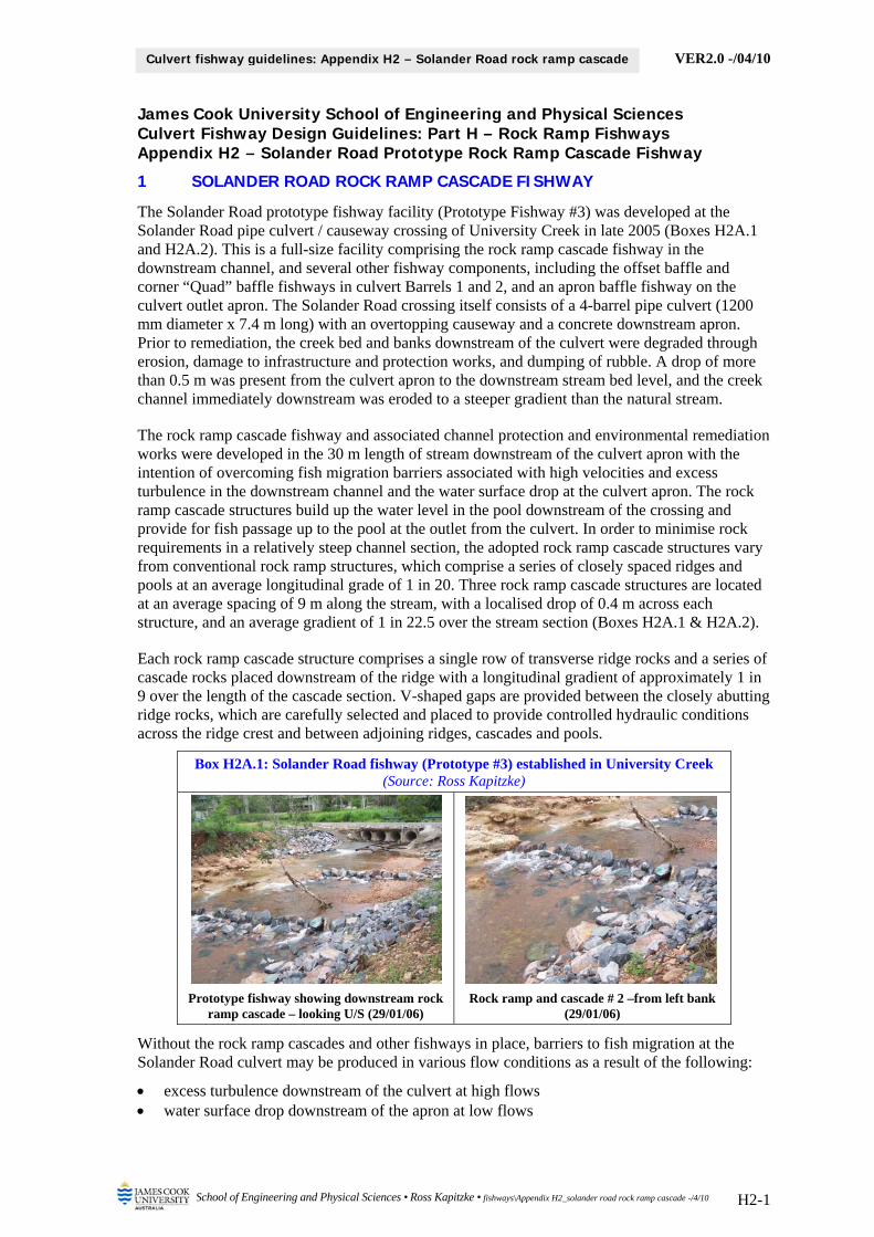
VER2.0 -/04/10
School of Engineering and Physical Sciences • Ross Kapitzke • fishways\Appendix H2_solander road rock ramp cascade -/4/10 H2-1
Culvert fishway guidelines: Appendix H2 – Solander Road rock ramp cascade
James Cook University School of Engineering and Physical Sciences Culvert Fishway Design Guidelines: Part H – Rock Ramp Fishways Appendix H2 – Solander Road Prototype Rock Ramp Cascade Fishway
1 SOLANDER ROAD ROCK RAMP CASCADE FISHWAY
The Solander Road prototype fishway facility (Prototype Fishway #3) was developed at the Solander Road pipe culvert / causeway crossing of University Creek in late 2005 (Boxes H2A.1 and H2A.2). This is a full-size facility comprising the rock ramp cascade fishway in the downstream channel, and several other fishway components, including the offset baffle and corner “Quad” baffle fishways in culvert Barrels 1 and 2, and an apron baffle fishway on the culvert outlet apron. The Solander Road crossing itself consists of a 4-barrel pipe culvert (1200 mm diameter x 7.4 m long) with an overtopping causeway and a concrete downstream apron. Prior to remediation, the creek bed and banks downstream of the culvert were degraded through erosion, damage to infrastructure and protection works, and dumping of rubble. A drop of more than 0.5 m was present from the culvert apron to the downstream stream bed level, and the creek channel immediately downstream was eroded to a steeper gradient than the natural stream.
The rock ramp cascade fishway and associated channel protection and environmental remediation works were developed in the 30 m length of stream downstream of the culvert apron with the intention of overcoming fish migration barriers associated with high velocities and excess turbulence in the downstream channel and the water surface drop at the culvert apron. The rock ramp cascade structures build up the water level in the pool downstream of the crossing and provide for fish passage up to the pool at the outlet from the culvert. In order to minimise rock requirements in a relatively steep channel section, the adopted rock ramp cascade structures vary from conventional rock ramp structures, which comprise a series of closely spaced ridges and pools at an average longitudinal grade of 1 in 20. Three rock ramp cascade structures are located at an average spacing of 9 m along the stream, with a localised drop of 0.4 m across each structure, and an average gradient of 1 in 22.5 over the stream section (Boxes H2A.1 & H2A.2).
Each rock ramp cascade structure comprises a single row of transverse ridge rocks and a series of cascade rocks placed downstream of the ridge with a longitudinal gradient of approximately 1 in 9 over the length of the cascade section. V-shaped gaps are provided between the closely abutting ridge rocks, which are carefully selected and placed to provide controlled hydraulic conditions across the ridge crest and between adjoining ridges, cascades and pools.
Box H2A.1: Solander Road fishway (Prototype #3) established in University Creek (Source: Ross Kapitzke)
Prototype fishway showing downstream rock ramp cascade – looking U/S (29/01/06)
Rock ramp and cascade # 2 –from left bank (29/01/06)
Without the rock ramp cascades and other fishways in place, barriers to fish migration at the Solander Road culvert may be produced in various flow conditions as a result of the following:
excess turbulence downstream of the culvert at high flows water surface drop downstream of the apron at low flows
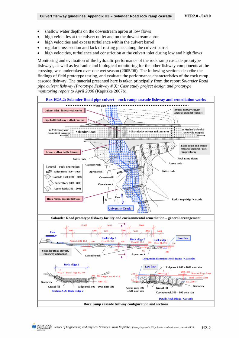
VER2.0 -/04/10
School of Engineering and Physical Sciences • Ross Kapitzke • fishways\Appendix H2_solander road rock ramp cascade -/4/10 H2-2
Culvert fishway guidelines: Appendix H2 – Solander Road rock ramp cascade
shallow water depths on the downstream apron at low flows high velocities at the culvert outlet and on the downstream apron high velocities and excess turbulence within the culvert barrel regular cross section and lack of resting place along the culvert barrel high velocities, turbulence and constriction at the culvert inlet during low and high flows
Monitoring and evaluation of the hydraulic performance of the rock ramp cascade prototype fishways, as well as hydraulic and biological monitoring for the other fishway components at the crossing, was undertaken over one wet season (2005/06). The following sections describe the findings of field prototype testing, and evaluate the performance characteristics of the rock ramp cascade fishway. The material presented here is taken principally from the report Solander Road pipe culvert fishway (Prototype Fishway # 3): Case study project design and prototype monitoring report to April 2006 (Kapitzke 2007b).
Box H2A.2: Solander Road pipe culvert – rock ramp cascade fishway and remediation works
Solander Road prototype fishway facility and environmental remediation – general arrangement
Rock ramp cascade fishway configuration and sections
Solander Road to Medical School & Townsville Hospital
to Veterinary and Biomedical Sciences
Culvert inlet / fishway exit works
Water pipe
Bypass fishway culvert and exit channel (future)
4–Barrel pipe culvert and causeway
NFlow
Rock ramp / cascade fishway Rock ramp ridge / cascade
Table drain and bypass entrance channel / rock ramp fishway
Batter rock
Concrete sill
Apron rock
Rock ramp ridges
Apron rock
University Creek
Apron – offset baffle fishway
Cascade rock
Batter rock
Pipe baffle fishway – offset / corner
Cascade rock Legend – rock protection
Ridge Rock (800 – 1000)
Cascade Rock (500 – 800)
Batter Rock (500 – 800)
Apron Rock (300 – 500)
Longitudinal Section: Rock Ramp / Cascades
Section A-A: Rock Ridge 2
Low flow
Solander Road culvert, causeway and apron
Flow
Cascade rock
10 000 9000 8000
Apron rock
Rock ridge 3 Rock ridge 2 Crest RL 17.8
Apron sill RL 18.2
3600 36003000 2000 2000 2000 2400
Rock ridge 1 200
600
200
400
200
400
200
200
A
A
Crest RL 18.2Crest RL 17.4
Detail: Rock Ridge / Cascade
Geofabric
Ridge rock 800 – 1000 nom size
200 - 300 Ridge Crest RL 17.8
600 - 700
Top of ridge RL 19.0 2
1
Rock ridge 2
Gravel fill
200 - 300 Nominal Ridge Crest
200 - 300 500
Nom. Cascade Crest
200
Ridge rock 800 – 1000 nom size 9
1
Cascade rock 500 – 800 nom size
Apron rock 300 – 500 nom size
Geofabric Gravel fill
Low flow

VER2.0 -/04/10
School of Engineering and Physical Sciences • Ross Kapitzke • fishways\Appendix H2_solander road rock ramp cascade -/4/10 H2-3
Culvert fishway guidelines: Appendix H2 – Solander Road rock ramp cascade
2 PROTOTYPE ROCK RAMP CASCADE FISHWAY HYDRAULIC MONITORING
Field monitoring of the Solander Road rock ramp cascade fishway (Prototype #3) was undertaken in conjunction with monitoring of the Solander Road pipe culvert and apron baffle fishways (see Guidelines Part G) and the adjoining Discovery Drive prototype fishways (see Guidelines Part F). This was part of an integrated monitoring, modelling and evaluation plan for University Creek prototype fishways that set out to evaluate performance in accordance with the design objectives for the fishways.
For the Solander Road rock ramp cascade fishway, the field work included first level hydraulic monitoring in and adjacent to the fishway, and biological monitoring of the stream reaches adjoining the Solander Road and Discovery Drive crossings. No direct observations of fish movement through the rock ramp cascade fishway were undertaken due to restricted opportunities during flow events in University Creek.
Physical monitoring of the prototype rock ramp cascade fishway examined the hydraulic characteristics of the fishway and the overall effectiveness of the facility under a range of flow conditions in University Creek. The hydraulic monitoring used a flow meter to determine velocity measurements, and direct measurements, observations, photographs and video to examine water depths and flow profiles associated with the fishway during periods of relevant flow. Water depth and flow meter measurements were undertaken by access in the stream during low level flows, subject to operational safety provisions.
The aims of physical / hydraulic field monitoring of the prototype and in the stream were to:
examine and measure flow depth, velocity, flow pattern and discharge at various locations within the prototype fishway for a range of flow conditions and discharges
integrate hydraulic monitoring and evaluation with biological monitoring and other studies contribute to evaluation of the prototype culvert fishway and to determination of design
parameters for other culvert fishway facilities. follow operational and safety procedures for access and monitoring of the prototype facility
2.1 Hydraulic monitoring equipment and methods
Flow measurements and observations (velocities, flow depths, flow patterns and fishway performance) at the Solander Road prototype rock ramp cascade fishway were undertaken for a range of flow conditions, mainly in low flow conditions of less than 0.5 m stream flow depth. Observational data were recorded with still and video photography and sketches, and velocity measurements were taken using the Swoffer Instruments Model 3000 data logging flow meter (Box H2A.3). Flow depths were measured at each velocity point with a graduated rod.
Box H2A.3: Hydraulic monitoring of rock ramp fishway (Source: Ross Kapitzke)
Velocity and flow depth measurements at rock ramp cascade # 2 (29/01/06)
Velocity and flow depth measurements at rock ramp cascade # 3 (29/01/06)
Velocities and flow depths were obtained in and adjacent to the flow slots between rocks on the rock ramp cascade fishways. The flow meter propeller was oriented into the flow to correspond

VER2.0 -/04/10
School of Engineering and Physical Sciences • Ross Kapitzke • fishways\Appendix H2_solander road rock ramp cascade -/4/10 H2-4
Culvert fishway guidelines: Appendix H2 – Solander Road rock ramp cascade
to the direction of maximum velocity at the point, two measurements were taken, and the average value adopted. The height of the flow meter above the stream bed was commonly set in the range 50 – 100 mm for the tests, but velocity measurement depths below the water surface were varied to obtain velocity profiles within the open channel and rock ramp fishway sections.
2.2 Hydraulic monitoring results for 2006
Velocities, depths and flow patterns were measured and observed in a series of events during the 2005/06 wet season, following installation of the prototype fishway in December 2005. Over 800 mm of rain fell on the University Creek catchment during the wet season period January – April 2006, causing the creek to flow for most of this time, and to retain water within the fish habitat pools in the upper creek reaches until May / June 2006. Hourly and daily rainfall data for the January and April events were obtained for Bureau of Meteorology recording stations adjacent to the University Creek catchment.
Observations of flow in the downstream channel section and within the rock ramp cascades were made regularly during the 2006 monitoring period, including visual, photographic and video observations during the flow events of 24 – 28 January and 06 – 11 April 2006. Velocity and flow depth data were obtained at the cascades under low flow conditions on 29/01/06 when the headwater gauge reading at the Solander Road pipe culvert was about 15 cm. These results are presented below (Box H2A.4), and photographic records of flow conditions for the downstream channel and the individual cascades at various stages of the January and April flow events are presented in Box H2A.5.
Fish movement observations and biological monitoring of adjoining reaches of University Creek undertaken during the January and April events did not include detailed biological monitoring of the Solander Road rock ramp cascade fishway. Surveys by Webb (2006) showed however that there were no apparent restrictions to fish passage through the rock ramp cascade fishway during this period, with a total of 6 native fish species observed in reaches immediately upstream and downstream of the Solander Road crossing.
2.3 Summary of findings – physical monitoring of prototype baffle fishways
Major outcomes and findings from the physical monitoring of the Solander Road rock ramp cascade fishway for 2005/06 are presented in Box H2A.6. The limited monitoring undertaken to date has provided useful information on fishway performance, the nature of the fishway designs, and the hydraulic characteristics of the fishway. Further hydraulic and biological monitoring and evaluation of the field prototype fishways is required to supplement data so far obtained.
Box H2A.4: Rock ramp cascade fishways in downstream channel – water surface drops, velocities and flow depths across rock ridges – low flow 29/01/06
Rock ridge / cascade
Nominal water surface drop across rock ridges
Approach flow immediately upstream of slots (velocity and depth)
Flow through slots (velocity and depth)
Flow immediately downstream of slots (velocity and depth)
Rock ridge # 1 250 mm 0.2 m/s to 0.5 m/s
100 mm to 200 mm
1.2 m/s to 1.8 m/s
50 mm to 150 mm
0.8 m/s to 1.2 m/s
100 mm to 300 mm
Rock ridge # 2 270 mm 0.3 m/s to 0.6 m/s
100 mm to 350 mm
1.2 m/s to 2.1 m/s
100 mm to 150 mm
0.8 m/s to 1.3 m/s
150 mm to 400 mm
Rock ridge # 3 250 mm 0.1 m/s to 0.6 m/s
150 mm to 450 mm
1.2 m/s to 1.9 m/s
100 mm to 200 mm
0.6 m/s to 1.5 m/s
150 mm to 450 mm

VER2.0 -/04/10
School of Engineering and Physical Sciences • Ross Kapitzke • fishways\Appendix H2_solander road rock ramp cascade -/4/10 H2-5
Culvert fishway guidelines: Appendix H2 – Solander Road rock ramp cascade
Box H2A.5: Flow characteristics in rock ramp cascade fishway (Source: Ross Kapitzke)
Rock ridge cascade # 1 and # 2 after January flow – looking from left bank (29/01/06)
Rock ridge cascade # 2 after January flow – looking from right bank (29/01/06)
Rock ridge cascade # 1 and # 2 after April flow – looking from left bank (09/04/06)
Rock ridge cascade # 1 and # 2 after April flow – looking from right bank (09/04/06)
Box H2A.6: Major findings from Solander Road rock ramp cascade fishway – to April 2006
Flow cases and water level conditions velocity and flow depth data were obtained at the rock ramp cascades on 29/01/06, and photographic records of flow
were evaluated for this event and others on 26/01/06 and 09/04/06 headwater conditions for these events ranged from 10 cm to 80 cm at the Solander Road pipe culvert inlet, with
headwater depths of about 15 cm applying for the velocity measurements at the cascades on 29/01/06 Hydraulic performance – velocities and flow patterns the slots between the ridge rocks in the rock ramp cascades are effective in producing local spill sections through
water surface drops in the order of 250 mm in the very low flow conditions the relatively narrow elongated vertical shape of the slots maintains velocities typically less than 2 m/s and depths of
150 mm through the short extent of slot linking downstream cascade sections with pools upstream of the rock ridges the water surface drop at the rock ridges decreases for increased flow through and over the ridge rock slots, and the
slot velocity and length of travel for fish between downstream and upstream pools increases only marginally as flow depth increases up to low levels of submergence of the rock ridges
water depths in the rock cascade sections immediately downstream of the rock ridges are typically around 300 mm, and the pools between the rock ramp / cascade features are typically in excess of 300 mm deep
for greater flow levels overtopping the ridge rocks as weir flow, velocities increase at the ridge rocks, in the approach channel sections, and through much of the downstream channel
Erosion, sediment and debris characteristics sediment deposition in the stream channel adjacent to the rock ramp cascades is re-establishing the low flow channel
form, enhancing stream channel stability, and reinforcing and improving the function of the rock ramps and pools fine sediment deposition within the ridge rock matrix and the adjoining apron rock has enhanced water holding
capabilities for the pools smaller rocks within the cascade section of the rock ramp structures may be dislodged in high energy flow, and
ongoing monitoring and reinstatement of selected rocks will be required to ensure fish passage function and long term integrity of these features are retained
Suggested further design development, physical monitoring and prototype testing hydraulic testing and evaluation of the rock ramp cascade fishways, involving velocity, depth and flow pattern
observations and measurements for a range of flow depths up to submergence of the rock ridge structures monitoring and evaluation of the integrity of the overall culvert structure and fish passage facility, and performance
of the fishways in terms of sediment and debris passage and self cleansing

VER2.0 -/04/10
School of Engineering and Physical Sciences • Ross Kapitzke • fishways\Appendix H2_solander road rock ramp cascade -/4/10 H2-6
Culvert fishway guidelines: Appendix H2 – Solander Road rock ramp cascade
3 BIBLIOGRAPHY Kapitzke, I.R. 2006a, Bruce Highway Corduroy Creek to Tully planning study Provisions for fish passage
– Road corridor scale Assessment Task 1A, report to Maunsell Australia and Department of Main Roads. Kapitzke, I.R. 2006b, Discovery Drive offset baffle fishway for box culverts (Prototype Fishway # 1): Case
study project design and prototype monitoring report to April 2005, report to Dept of Main Roads. Kapitzke, I.R. 2006c, Douglas Arterial Project rock ramp fishway for open channels (Prototype Fishway #
2): Case study project design and prototype monitoring report to April 2005, report to Dept Main Roads. Kapitzke, I.R. 2007a, Bruce Highway Corduroy Creek to Tully High School Provisions for fish passage –
Preliminary Design Assessment Tasks 1B and 2, report to Maunsell Australia and Dept of Main Roads. Kapitzke, I.R. 2007b, Discovery Drive corner baffle fishway for box culverts (Prototype Fishway # 4):
Case study project design and prototype monitoring report to April 2006, report to Dept of Main Roads. Kapitzke, I.R. 2007c, Solander Road pipe culvert fishway (Prototype Fishway # 3): Case study project
design and prototype monitoring report to April 2006, report to Department of Main Roads. Webb, A.C. 2006, Fishway biomonitoring January – April 2006, report prepared by James Cook
University School of Tropical Biology.
Ross Kapitzke James Cook University School of Engineering and Physical Sciences April 2010 – VER2.0