first thz measurements at facet ziran wu, alan fisher, henrik loos facet 2011 users meeting...
Post on 19-Dec-2015
215 views
TRANSCRIPT

First THz Measurementsat FACET
Ziran Wu, Alan Fisher, Henrik Loos
FACET 2011 Users Meeting
2011-08-29

The Terahertz Gap
• “Terahertz” is the gap between mm waves and mid-infrared– 1 mm to 10 µm, or 0.3 to 30 THz– Few sources, few optical components, and poor instruments
• Pulse energy is difficult to measure: Joulemeters are uncalibrated
• Laser-based THz sources are insufficient for pump-probe– Broadband, nearly unipolar pulses are made by:
• Photoconductive switching• Optical rectification• Laser-gas interactions• Typical fields of 20 MV/m; pulse energies of 20 µJ
– Difference-frequency mixing makes a high-field, few-cycle transient• Fields as high as 10 GV/m; pulse energies again of 20 µJ
• We want a quasi-unipolar pulse of ~10 GV/m and >100 µJ
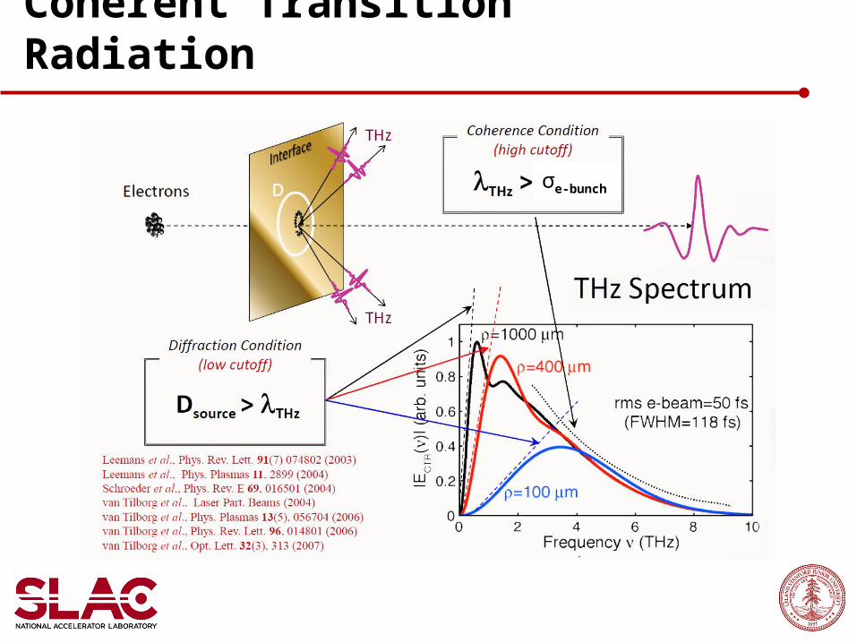
Coherent Transition Radiation
σe-bunch
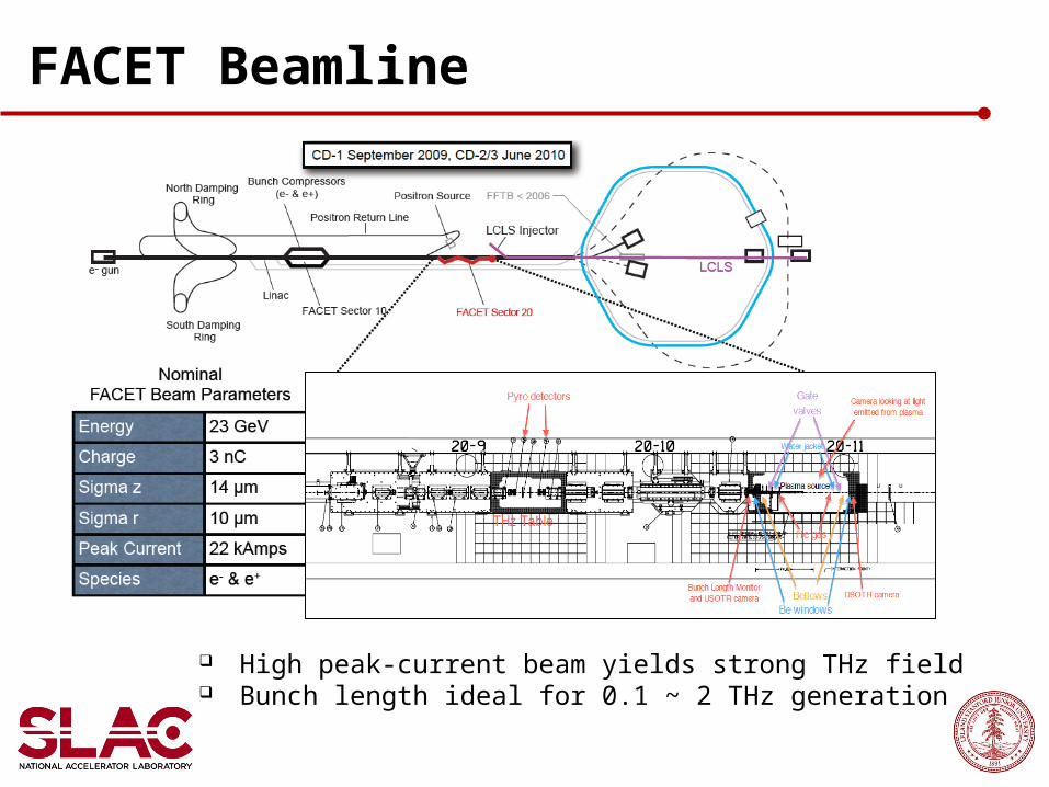
FACET Beamline
High peak-current beam yields strong THz field Bunch length ideal for 0.1 ~ 2 THz generation
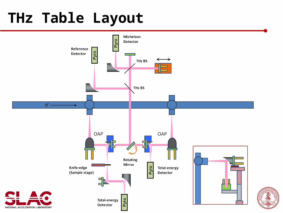
THz Table Layout

THz Table Setup
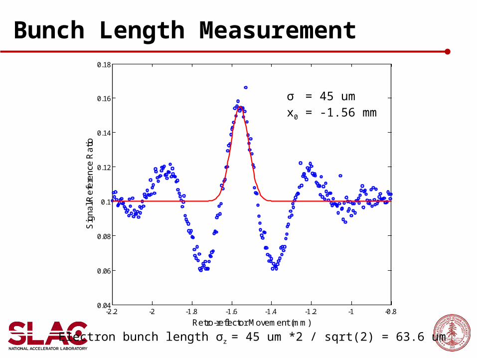
Bunch Length Measurement
-2.2 -2 -1.8 -1.6 -1.4 -1.2 -1 -0.80.04
0.06
0.08
0.1
0.12
0.14
0.16
0.18
Retro-reflector Movement (mm)
Sig
na
l/Re
fere
nce
Ra
tioσ = 45 umx0 = -1.56 mm
Electron bunch length σz = 45 um *2 / sqrt(2) = 63.6 um

THz Spectrum
Peak at ~400 GHz High-end cutoff at ~700 GHz (429 um) σz ≈ 429 um /2π = 68.2 um

Beam waist (radius): ~3.5 mm horizontal and ~2 mm vertical Consistent with ~1 mm peak radiation wavelength Coincide with e-beam having much larger horizontal size at THz table
Beam Size at Focus
5 6 7 8 9 10 11 12 1310
15
20
25
30
35
40
45
50
55
KE Y-scan (mm)S
ig/R
ef R
atio
6 8 10 12 14 16 180
10
20
30
40
50
60
KE X-scan (mm)
Sig
/Ref
Rat
io

Simulated Beam Size
Vertical size 2.4 mm, single peak Horizontal size 2.9 mm, double peak (Can we see it in knife edge scan?) Using sigma_z = 100 um in the simulation
y (
mm
)
x ( mm)-10 0 10
-10
-5
0
5
10
-10 0 100
10
20
30
40
50
x or y (mm)C
ount
s
λ = 1 mm VerticalHorizontal

Simulated THz Propagation
Vert. polarizationλ = 1 mm
e-Beam size 2.1 mm x 75 µm
Horizontal pol.Vertical pol.
Distance
Rad
ius
Main contribution from vertical pol. due to flat beam
Beam radius
Transmission
-15 -10 -5 0 5 10 15-50
0
50
100
Time (ps)
Ele
ctric
Fie
ld (
MV
/cm
)
0 10 20 30 40 500
20
40
60
80
100
Wavenumber (cm-1)
For
mfa
ctor
(%
) Vertical transmissionBunch form factorRadiation spectrum
Field at detector

Comparison with Experiment
0 10 20 30 40 500
0.2
0.4
0.6
0.8
1
Wave number (cm-1)
(arb
. un
its)
Measured spectrumSimulated spectrumWater absorption
Low and high roll-off frequencies don’t quite agree Highly depend on e- bunch length Detector responsivity spectrum is desired

At Different Bunch Compressions
BLEN pyro signal as direct indication of bunch length
Larger pyro readShorter bunch
Filters in the way:Si viewport (3mm)Nitrocellulose BS (2um)Pyro detector (50um crystal and coating)Transverse bunch size
-1.6 -1.55 -1.5 -1.45 -1.4 -1.35 -1.3 -1.25 -1.2 -1.153
4
5
6
7
8
9
10
11
12
13
Delay Stage Position (mm)
Sig
/Ref
Rat
io
Pyro 1000
Pyro 800
Pyro 600Pyro 400
Pyro 1000

Diagnostics to Be Done
Per-pulse total energy measurement
Peak field estimation based on bunch length and focal size
A different detector for the autocorrelator? Characterize the current pyro
Bunch length and transverse e-beam size variations
Downstream foil measurements
Possible formation length study

Inducing Magnetic Anisotropy
Need strong B field for magnetic switching in a thin-film metallic ferromagnet
FACET THz beam may provide short and intense enough pulse
Sample ready for THz exposure; Arrangement required for single shot per sample (Single-shot operation or chop at sub-1Hz)

R&D to Bring THz to Laser Room
Ideal for THz-optical pump probe experiment
Needs 10s’ of meters THz transport line
Relay imaging system with large and frequent OAPs (~200 mm dia., ~5 m EFL, every ~10 m)
Experience gain of long-distance THz transportation
Possibility of bring laser onto THz table too

Thank You !

Silicon Viewport
Curves