first results from the lhc beam instrumentation systems
TRANSCRIPT

LHC
-Per
form
ance
-Not
e-00
622
/04/
2009
LHC Performance Note 0062009-04-22
First Results from the LHC Beam Instrumentation Systems
BE-BI
Summary
This note summarises the early results obtained from the majority of the LHC beam instrumentation systems during the synchronisation tests of the 8th – 10th August, 22nd – 24th August, 5th-7th September and from the first week of full LHC operation.
1. INTRODUCTION The majority of the LHC beam instrumentation systems were capable of measuring beam
parameters either during the three LHC injection synchronisation tests or with the first circulating beam in the machine. This includes the two large distributed systems, the beam position and beam loss systems, as well as the BTV system, the fast and DC BCT systems, the tune measurement system and the wire scanners. The fast timing system was also extensively used to synchronise most of the instrumentation. The only systems for which there is no data are the synchrotron light monitors (due to the non availability of the undulators), the ionisation profile monitors (due to the absence of a gas injection system) and the luminosity monitors.
This note will comment on the results to date, some of the problems observed and improvements to be implemented before next year’s LHC run.
2. THE LHC BPM SYSTEM The LHC BPM system is comprised of 1054 beam position monitors. The majority (912)
are 24mm button electrode BPMs located in each of the arc quadrupole cryostats (SSS). A further 104 are enlarged (34mm or 40mm) button electrode BPMs for the stand alone quadrupoles and TOTEM stations. The remaining 38 are stripline electrode BPMs, with 24 of these used for their directivity in the common beam pipe regions where they measure both beams, and the remainder used for their higher signal level in the large diameter vacuum chambers around the dump lines.
The beam position acquisition electronics [1] is split into two parts an auto-triggered, analogue, position to time normaliser [2] which sits in the tunnel and an integrator/digitiser/processor VME module located on the surface. Transmission of the time encoded position information from tunnel to surface is carried out using a fibre-optic link. A WorldFIP fieldbus is used to provide the slow control to the tunnel stations, including the front-end sensitivity selection and calibration mode. Each BPM measures in both the horizontal and vertical plane, resulting in a total of 2156 electronic channels. All channels are individually calibrated and corrected for the geometric non-linearity of the attached BPM.
This is an internal CERN publication and does not necessarily reflect the views of the LHC project management.

- 2 -
2.1 First Results from the LHC BPM System The beam threading mode, also known as FIFO mode, is used to provide the first turn
position data to the operator GUI (YASP – Yet Another Steering Program). This is a totally asynchronous acquisition mode, where any triggers obtained within a specified gate are stored, processed & published. When used with a single bunch, as was the case for all LHC measurements to date, each entry represents the position on a consecutive turn and can therefore be used to reconstruct the trajectory on the Nth turn.
Figure 1. One of the first Beam 1 trajectories from injection in Point 2 to IR3 (8/8/2008)
From the very first shot into LHC the BPM system gave very nice results while operating in this asynchronous mode (see Fig 1). Combined with the powerful YASP software it allowed quick diagnostics to be made on BPM polarity and machine optics errors. Fig 2 shows an example, again from the first synchronisation test, where both an optics error (traced to the wrong polarity of an MQTL magnet) and a BPM polarity error are clearly visible.
Horizontal kick
Vertical kick
Horizontal kick
Vertical kick
Figure 2. On-line analysis of LHC BPM data showing a phase advance error in the horizontal plane and a BPM polarity error (circled) in the vertical plane (8/8/2008)
2.2 Test of the Intensity Limit for the BPM System The LHC BPM system can work in one of 2 sensitivity ranges – high or low. The
threshold for the sensitivity change is conceived such that any reflections at the level of -20dB do not retrigger the system. In the high sensitivity setting the BPM system was foreseen to

- 3 -
work correctly with bunch intensities in the range 2×10⁹ to 2×10¹⁰ protons, with the low sensitivity working from 2×10¹⁰ to 2×10¹¹ protons. In order to test the lower limit for auto-trigger detection the bunch intensity was varied from below 1×10⁹ to around 3×10⁹, while counting the number of correctly triggered BPMs in the arc 2-3. Fig 3 shows the results obtained, along with the predicted performance of a typical electronics channel measured in the laboratory. The lower limit for correct BPM functioning can therefore be stated as being 1.5×10⁹ protons per bunch.
-1000-800-600-400-200
0200400600800
1000
1E+08 1E+09 1E+10 1E+11
Bunch Intensity (protons)
LHC
Arc
BP
M E
rror
( μm
)
0.0
20.0
40.0
60.0
80.0
100.0
BPM
Trig
ger R
ate
(%)
Linearity (Lab)Noise (Lab)Arc BPM Trigger Rate
Pilot
Figure 3. BPM auto-trigger threshold determination – HIGH sensitivity mode (10/8/2008)
The laboratory intensity scale had to be corrected by 5dB in order to match what was actually measured with the beam. There were 2 main sources found for this discrepancy: firstly the losses due to the final cabling and connections of the arc BPM were not fully taken into account, and secondly the high frequency response of the input low-pass filter was not correctly modelled in the simulation. A complete simulation of the whole system has now been obtained and was used to provide the results shown in Fig. 3. The agreement is seen to be extremely good, and will be basis for the calibration of the BPM intensity card which will be added to the system for the 2009 start-up.
2.3 Early Performance of the LHC BPM System The performance of the LHC BPM system has been characterised for very low intensity,
single bunch operation both in trajectory and orbit mode. Fig 4 shows the results from trajectory analysis (beam threading mode – see section 2.1) of 31 injections during the synchronisation tests for Beam 1.
BPM Index
Traj
ecto
ry rm
s(μ
m)
BPM Index
Traj
ecto
ry rm
s(μ
m)
Figure 4. Single shot pilot bunch stability – HIGH sensitivity mode (10/8/2008)
- 4 -
The overall rms variation in position over a timescale of ten minutes is generally seen generally to be between 150-400μm. This order of magnitude is consistent with the electronic noise estimations shown in Fig 3 for bunch intensities in the range 2×10⁹ to 5×10⁹ protons.
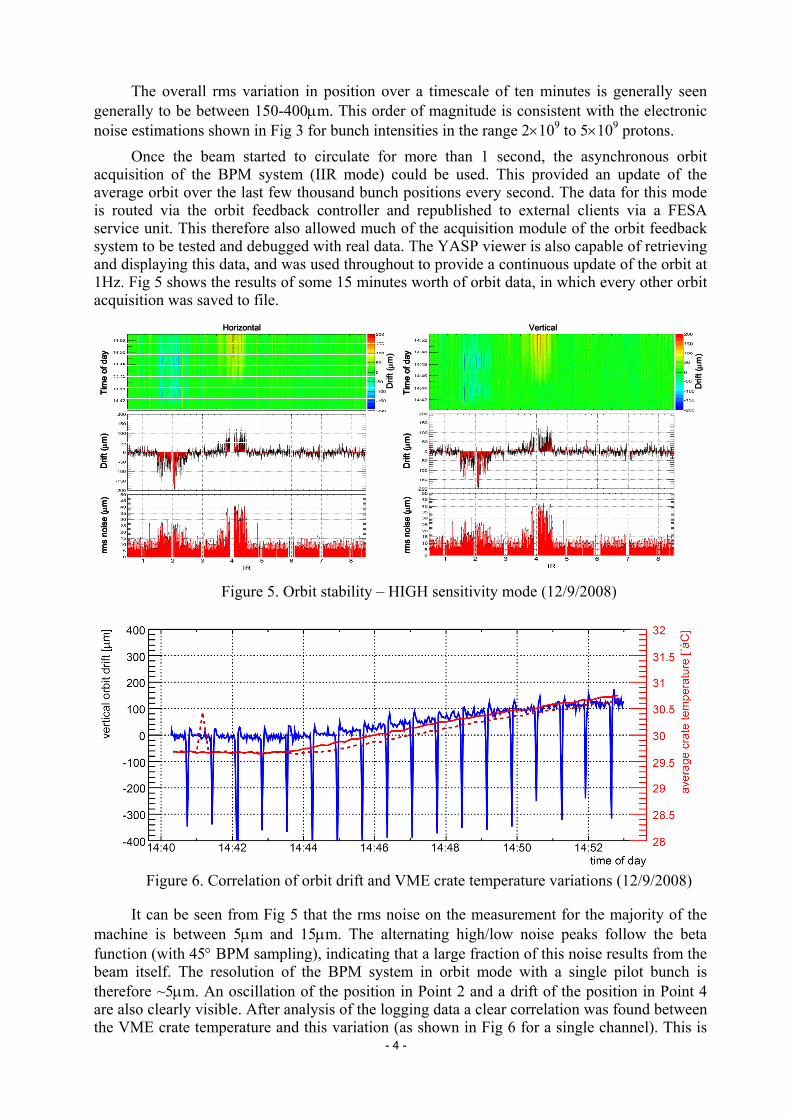
Once the beam started to circulate for more than 1 second, the asynchronous orbit acquisition of the BPM system (IIR mode) could be used. This provided an update of the average orbit over the last few thousand bunch positions every second. The data for this mode is routed via the orbit feedback controller and republished to external clients via a FESA service unit. This therefore also allowed much of the acquisition module of the orbit feedback system to be tested and debugged with real data. The YASP viewer is also capable of retrieving and displaying this data, and was used throughout to provide a continuous update of the orbit at 1Hz. Fig 5 shows the results of some 15 minutes worth of orbit data, in which every other orbit acquisition was saved to file.
Tim
e of
day
Drif
t (μm
)rm
sno
ise
(μm
)
Tim
e of
day
Drif
t (μm
)rm
sno
ise
(μm
)
Horizontal Vertical
Drif
t (μm
)
Drif
t (μm
)
Tim
e of
day
Drif
t (μm
)rm
sno
ise
(μm
)Ti
me
of d
ayD
rift (μm
)rm
sno
ise
(μm
)
Tim
e of
day
Drif
t (μm
)rm
sno
ise
(μm
)Ti
me
of d
ayD
rift (μm
)rm
sno
ise
(μm
)
Horizontal Vertical
Drif
t (μm
)
Drif
t (μm
)
Figure 5. Orbit stability – HIGH sensitivity mode (12/9/2008)
Figure 6. Correlation of orbit drift and VME crate temperature variations (12/9/2008)
It can be seen from Fig 5 that the rms noise on the measurement for the majority of the machine is between 5μm and 15μm. The alternating high/low noise peaks follow the beta function (with 45° BPM sampling), indicating that a large fraction of this noise results from the beam itself. The resolution of the BPM system in orbit mode with a single pilot bunch is therefore ~5μm. An oscillation of the position in Point 2 and a drift of the position in Point 4 are also clearly visible. After analysis of the logging data a clear correlation was found between the VME crate temperature and this variation (as shown in Fig 6 for a single channel). This is

- 5 -
easily explained in Point 4, where the acquisition system is located in a small room in SX4 and cooled by two standard laboratory air conditioning units. In the middle of these acquisitions one of the units was switched off, leading to a 1° rise in the air temperature by the end of the last recorded orbit. All the other systems are located in SR buildings, which are large, centrally cooled hangars. The temperature in SR2 was found to vary periodically and correlates nicely with the orbit variations observed. The source of this variation in this particular SR is still under investigation. It is clear that the orbit drifts produced due to the temperature dependence of the BPM digitisation modules located on the surface is currently unacceptable for nominal LHC operation. This issue will have to be addressed during the shutdown.
In addition to the orbit drift visible in Fig 6 a regular spike occurring with the period of the SPS supercycle is observed in the orbit data. The source of this perturbation has been traced to the stray field coming from the septum magnets (MSI) in Points 2 and 8 which are pulsed with the TI2 and TI8 transfer lines. In order to avoid this both MSIs will in future be continually powered.
3. THE LHC BLM SYSTEM The purpose of the LHC BLM system is threefold: to protection the LHC equipment from
damage; to avoid beam induced magnet quenches; to observe losses for machine parameter tuning such as the adjustment of collimators. The protection requirements led to the placement of detectors at all likely loss locations, resulting in a total of 4000 installed monitors. The majority of these are located around the quadrupole magnets and in the collimator regions. The signals of almost all monitors are compared with pre-defined threshold values which, if exceeded, result in a retraction of the beam permit signal and consequently a beam dump. The BLM monitor acquisition systems for both half sectors served by a given access point are concentrated on the surface, with a redundant link to the beam interlock system transmitting the beam permit signal to the dump system.
3.1 Early Performance of the LHC BLM System Figure 7 shows the readings of all ionisation chambers around the ring during single turn
operation with Beam 1. The bias level of the acquisition is given by the current injected into each channel to continuously test their status. A variation in this test current can be seen for the individual channels and results from different settings in the front-end electronics. This will have to be adjusted in all front-end cards before the next running period. The almost two orders of magnitude larger reading left of IP1 is due to the dump of the beam on the TCT collimator.
Figure 7. BLM readings along the ring (online display, logarithmic scale). Green bars show integrated signal over the last 5.2 seconds and red dots the threshold settings.
- 6 -
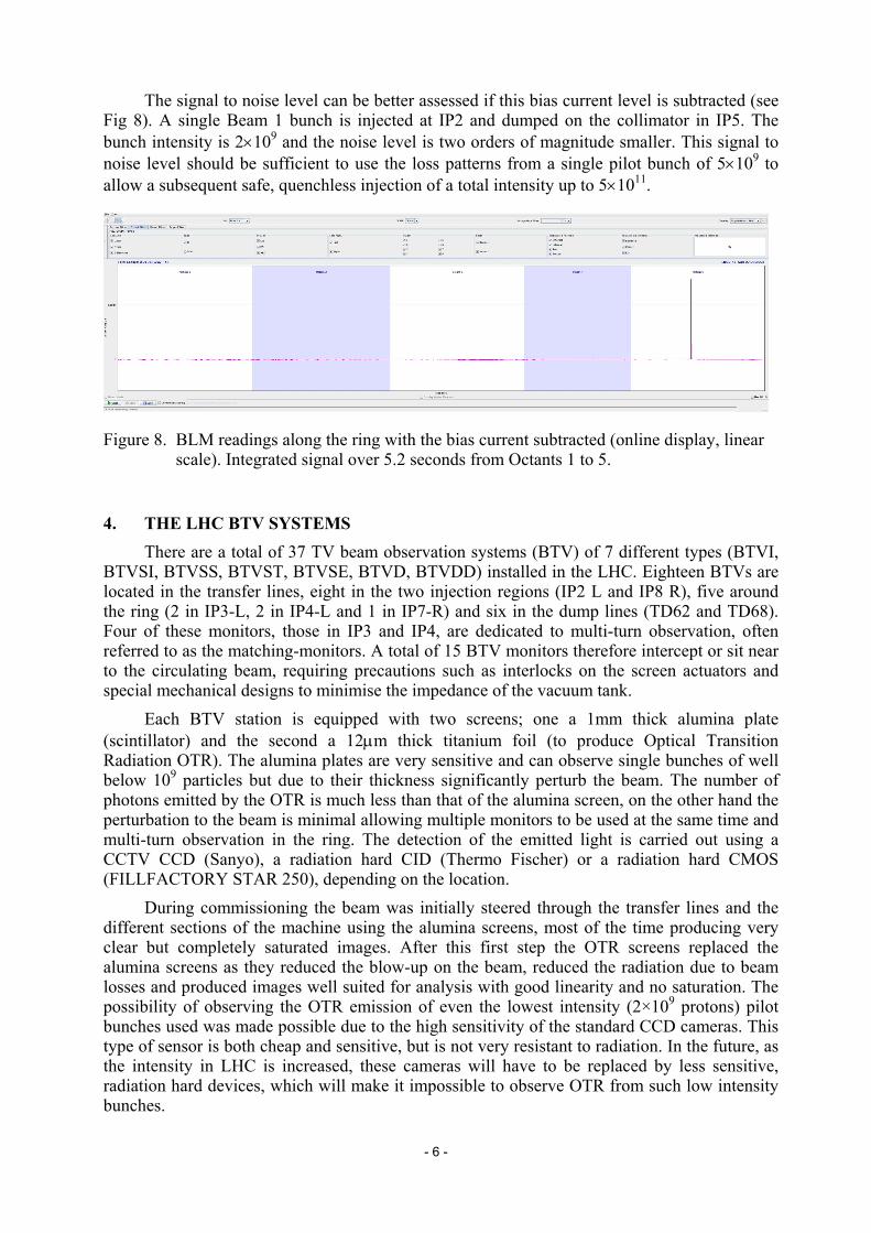
The signal to noise level can be better assessed if this bias current level is subtracted (see Fig 8). A single Beam 1 bunch is injected at IP2 and dumped on the collimator in IP5. The bunch intensity is 2×10⁹ and the noise level is two orders of magnitude smaller. This signal to noise level should be sufficient to use the loss patterns from a single pilot bunch of 5×10⁹ to allow a subsequent safe, quenchless injection of a total intensity up to 5×10¹¹.
Figure 8. BLM readings along the ring with the bias current subtracted (online display, linear scale). Integrated signal over 5.2 seconds from Octants 1 to 5.
4. THE LHC BTV SYSTEMS There are a total of 37 TV beam observation systems (BTV) of 7 different types (BTVI, BTVSI, BTVSS, BTVST, BTVSE, BTVD, BTVDD) installed in the LHC. Eighteen BTVs are located in the transfer lines, eight in the two injection regions (IP2 L and IP8 R), five around the ring (2 in IP3-L, 2 in IP4-L and 1 in IP7-R) and six in the dump lines (TD62 and TD68). Four of these monitors, those in IP3 and IP4, are dedicated to multi-turn observation, often referred to as the matching-monitors. A total of 15 BTV monitors therefore intercept or sit near to the circulating beam, requiring precautions such as interlocks on the screen actuators and special mechanical designs to minimise the impedance of the vacuum tank. Each BTV station is equipped with two screens; one a 1mm thick alumina plate (scintillator) and the second a 12μm thick titanium foil (to produce Optical Transition Radiation OTR). The alumina plates are very sensitive and can observe single bunches of well below 109 particles but due to their thickness significantly perturb the beam. The number of photons emitted by the OTR is much less than that of the alumina screen, on the other hand the perturbation to the beam is minimal allowing multiple monitors to be used at the same time and multi-turn observation in the ring. The detection of the emitted light is carried out using a CCTV CCD (Sanyo), a radiation hard CID (Thermo Fischer) or a radiation hard CMOS (FILLFACTORY STAR 250), depending on the location. During commissioning the beam was initially steered through the transfer lines and the different sections of the machine using the alumina screens, most of the time producing very clear but completely saturated images. After this first step the OTR screens replaced the alumina screens as they reduced the blow-up on the beam, reduced the radiation due to beam losses and produced images well suited for analysis with good linearity and no saturation. The possibility of observing the OTR emission of even the lowest intensity (2×10⁹ protons) pilot bunches used was made possible due to the high sensitivity of the standard CCD cameras. This type of sensor is both cheap and sensitive, but is not very resistant to radiation. In the future, as the intensity in LHC is increased, these cameras will have to be replaced by less sensitive, radiation hard devices, which will make it impossible to observe OTR from such low intensity bunches.
- 7 -
4.1 Acquisition and control The control of the BTV monitors is performed using a custom made VME board [3]. The VME crates are installed in underground areas (UA and US) in order to minimize cable length. This reduces the accessibility but minimises the cost and improves the performance of the monitors. This single VME card is very versatile and can control all types of BTV stations as well as acquiring and digitizing the images from all the different types of cameras.
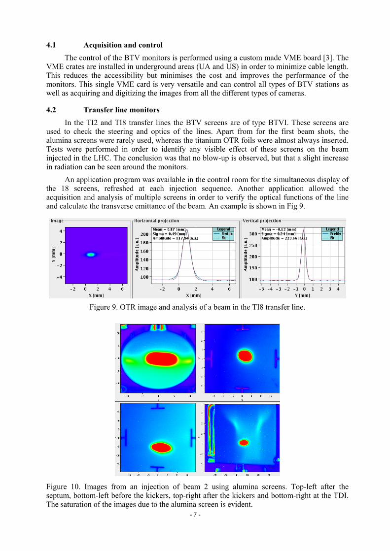
4.2 Transfer line monitors In the TI2 and TI8 transfer lines the BTV screens are of type BTVI. These screens are used to check the steering and optics of the lines. Apart from for the first beam shots, the alumina screens were rarely used, whereas the titanium OTR foils were almost always inserted. Tests were performed in order to identify any visible effect of these screens on the beam injected in the LHC. The conclusion was that no blow-up is observed, but that a slight increase in radiation can be seen around the monitors. An application program was available in the control room for the simultaneous display of the 18 screens, refreshed at each injection sequence. Another application allowed the acquisition and analysis of multiple screens in order to verify the optical functions of the line and calculate the transverse emittance of the beam. An example is shown in Fig 9.
Figure 9. OTR image and analysis of a beam in the TI8 transfer line.
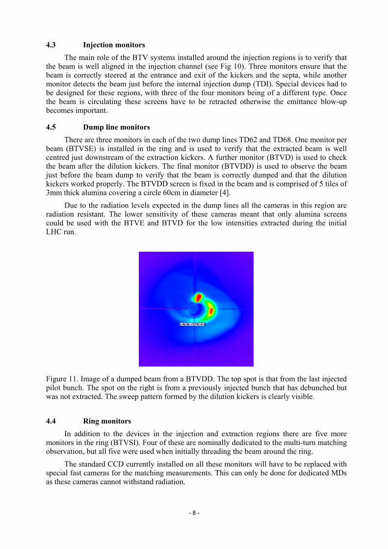
Figure 10. Images from an injection of beam 2 using alumina screens. Top-left after the septum, bottom-left before the kickers, top-right after the kickers and bottom-right at the TDI. The saturation of the images due to the alumina screen is evident.
- 8 -
4.3 Injection monitors The main role of the BTV systems installed around the injection regions is to verify that the beam is well aligned in the injection channel (see Fig 10). Three monitors ensure that the beam is correctly steered at the entrance and exit of the kickers and the septa, while another monitor detects the beam just before the internal injection dump (TDI). Special devices had to be designed for these regions, with three of the four monitors being of a different type. Once the beam is circulating these screens have to be retracted otherwise the emittance blow-up becomes important.
4.5 Dump line monitors There are three monitors in each of the two dump lines TD62 and TD68. One monitor per beam (BTVSE) is installed in the ring and is used to verify that the extracted beam is well centred just downstream of the extraction kickers. A further monitor (BTVD) is used to check the beam after the dilution kickers. The final monitor (BTVDD) is used to observe the beam just before the beam dump to verify that the beam is correctly dumped and that the dilution kickers worked properly. The BTVDD screen is fixed in the beam and is comprised of 5 tiles of 3mm thick alumina covering a circle 60cm in diameter [4]. Due to the radiation levels expected in the dump lines all the cameras in this region are radiation resistant. The lower sensitivity of these cameras meant that only alumina screens could be used with the BTVE and BTVD for the low intensities extracted during the initial LHC run.
Figure 11. Image of a dumped beam from a BTVDD. The top spot is that from the last injected pilot bunch. The spot on the right is from a previously injected bunch that has debunched but was not extracted. The sweep pattern formed by the dilution kickers is clearly visible.
4.4 Ring monitors In addition to the devices in the injection and extraction regions there are five more monitors in the ring (BTVSI). Four of these are nominally dedicated to the multi-turn matching observation, but all five were used when initially threading the beam around the ring. The standard CCD currently installed on all these monitors will have to be replaced with special fast cameras for the matching measurements. This can only be done for dedicated MDs as these cameras cannot withstand radiation.
- 9 -
4.6 Performance All the BTV monitors performed extremely well and were constantly in use during the synchronization tests and first beam in the LHC. They proved to be a reliable tool for operation, clearly indicating the progress made at each stage of commissioning. No real problem was observed and the performance of the system was above specifications. Notably the observation of bunches with only 2×10⁹ protons using OTR foils was not foreseen in the specifications, but was a very useful plus.
4.7 Outlook Several modifications will be carried out during the coming months and before the next run. In particular some new request from the interlock system will require modifications to the hardware in the monitors and possibly the need for extra cables. The FESA server and all other control glitches will be addressed by the BI and CO groups and shall be solved by the next start-up. Due to the expected radiation levels in the injection regions the CCD cameras will gradually have to be replaced with the less sensitive CID cameras, which will make it impossible to observe pilot bunches in OTR mode.
5. THE LHC BCT SYSTEMS Beam current transformers of two different kinds provide intensity measurements for the
beams circulating in the LHC rings, as well as for the transfer lines from the SPS to LHC and from LHC to the dumps. The transformers are installed in sections where the vacuum chamber is at room temperature.
5.1 The LHC BCTDC Systems The DC current transformers (BCTDC), designed and made at CERN, are installed in
LSS4R, some 152 meters away from IP4. The BCTDCs are based on the principle of magnetic amplifiers and measure the mean current of the circulating beam. Because of their operational importance, two independent systems (A and B) are installed per ring. Each system is comprised of a monitor and an analogue front-end module located in the tunnel connected to further analogue modules and a VME based digital acquisition system on the surface (SX4).
Four ranges, provided simultaneously, are used to cover the entire beam dynamic range from a few 109 to 5×10¹⁴ protons (~3μA to ~900mA). The BCTDC bandwidth is limited for noise reduction reasons to 20Hz, even though the natural bandwidth is in the order of 20kHz. The analogue signals of the four ranges are continuously acquired via a 12 bit ADC at 50Hz, with the choice of pertinent range being performed by the real time program running synchronously with the machine timing at 10Hz. The number of circulating charges is published at a 1Hz rate for general applications such as the fixed display and at a 10Hz rate for the Machine Protection System which uses the information for the calculation of the Safe Beam Flag.
5.1.1 First Results from the LHC BCTDC Systems The main application used to view the BCTDC acquisition was the fixed display which
was refreshed once per second and allowed the observation of circulating beam for more than 11000 turns. Fig 12 shows such an acquisition for beam 2 on September 12th 2008.
- 10 -
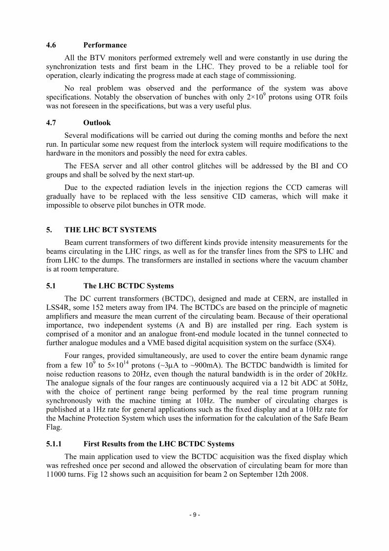
Figure 12. First circulating beam in ring 2 as seen by BCTDC A (12/9/2008)
In Fig 12 one can see 4 successive injections of single pilot bunches, ranging in intensity from 3.5×10⁹ to 6×10⁹ protons and circulation times from 100 seconds to 40 minutes. The BCTDC used for this measurement was the operational system (A) while the spare (B) was kept for test and development. The automatic range selection was set to the highest sensitivity with a full scale of 5×10¹¹ protons. The transmission to the Machine Protection System was tested but not activated.
The noise on the signal corresponds to an rms of 7×10⁸ protons for a 1 second integration time, which is equivalent to 1.3µA. A similar value is found for the slow fluctuations observed over several hours. This result is very good and meets expectations, although it is also a reminder that the BCTDC can only measure single pilot bunches with a limited accuracy of around 20%. A small, negative offset of ~2.5×10⁹ (4.5µA) was also observed which will be automatically corrected in the future.
Although these initial beam tests were very useful, there are still numerous things to be commissioned with beam. This includes the setting-up of BCTDC B on beam 2 and both BCTDCs on beam 1, automatic range selection, transmission to the Machine Protection System, beam lifetime measurement and automatic offset correction. In addition, an acquisition system allowing a single range to cover the entire dynamic range remains to be implemented.
5.2 First Results from the LHC Fast BCT Systems
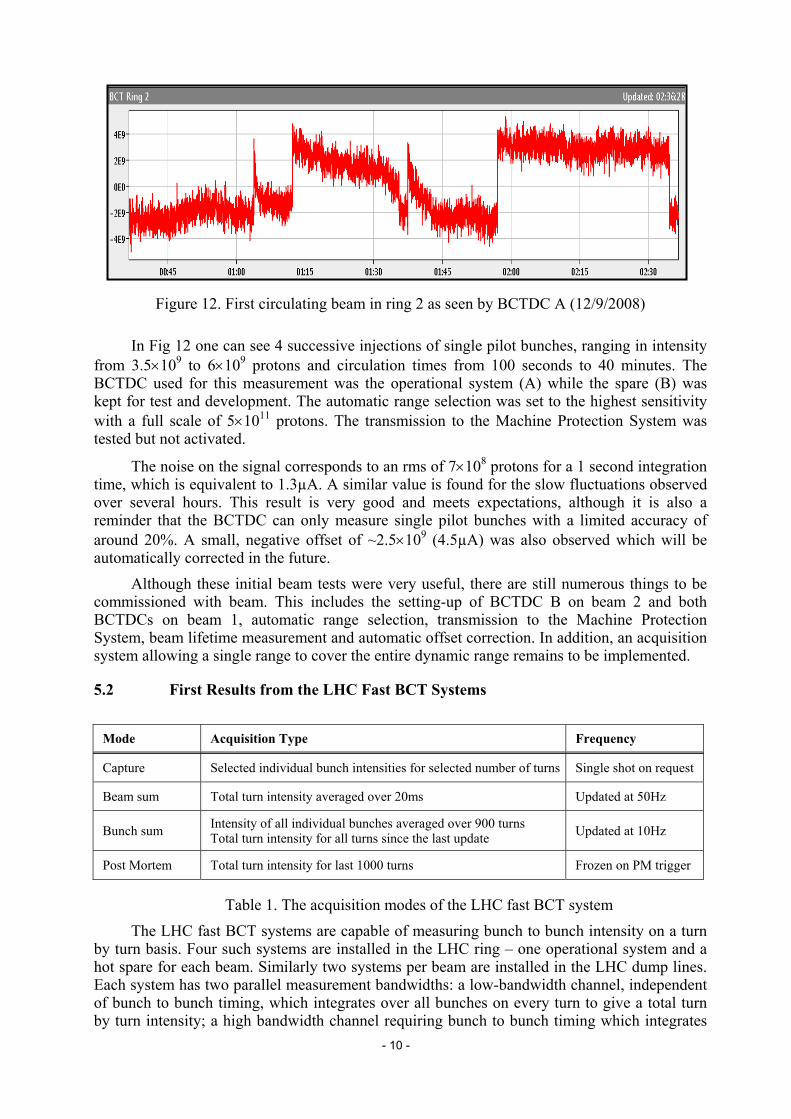
Mode Acquisition Type Frequency
Capture Selected individual bunch intensities for selected number of turns Single shot on request
Beam sum Total turn intensity averaged over 20ms Updated at 50Hz
Bunch sum Intensity of all individual bunches averaged over 900 turns Total turn intensity for all turns since the last update Updated at 10Hz
Post Mortem Total turn intensity for last 1000 turns Frozen on PM trigger
Table 1. The acquisition modes of the LHC fast BCT system The LHC fast BCT systems are capable of measuring bunch to bunch intensity on a turn
by turn basis. Four such systems are installed in the LHC ring – one operational system and a hot spare for each beam. Similarly two systems per beam are installed in the LHC dump lines. Each system has two parallel measurement bandwidths: a low-bandwidth channel, independent of bunch to bunch timing, which integrates over all bunches on every turn to give a total turn by turn intensity; a high bandwidth channel requiring bunch to bunch timing which integrates

- 11 -
over single bunches to give a bunch by bunch and turn by turn acquisition. Both of these channels are acquired simultaneously with two gain settings: a high gain used for bunch intensities less than 2×10¹⁰ and a low gain used for bunch intensities over 2×10¹⁰. Four basic modes of acquisition are provided to the user and are summarised in Table 1.
During the early injection tests where the beam passed through LSS4R, and in the subsequent commissioning with circulating beam the fast BCT was used in capture mode, triggered by the RF pre-injection pulse, to observe the LHC pilot bunch with intensities ranging from 2×10⁹ to 6×10⁹ protons (see Fig 13).
(a) (b) Figure 13. (a) An early shot of three consecutive turns as seen by the fast BCT system. (b) Bunch intensity of RF Captured beam decaying over hundreds of turns. This short time with beam in the LHC was very useful to verify the correct functioning of the complete acquisition chain from detector to the operator GUI. There are still numerous things to be addressed before the full functionality of the system is reached, including commissioning of the lifetime algorithm and items related to the machine-protection system such as beam presence flag transmission and fast beam current decay monitoring. The detectors and acquisition chains of the fast BCTs in the dump line still remain to be commissioned.
6. THE LHC WIRESCANNERS A total of 8 linear wire scanners are installed in LSS4 of the LHC (5L4.B2 and 5R4.B1)
for measuring the transverse density profile of the beam. Each beam is equipped with 2 wire scanners in both horizontal and vertical planes, with one available for operation and the other intended as a fully functional back-up. The scanning speed of all these systems is 1 ms-1.
6.1 First Results from the LHC Wire Scanners Only beams with very low intensity were available for testing the LHC wirescanners
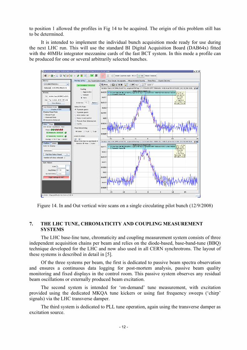
(2×10⁹ to 6×10⁹ protons circulating at 450 GeV). The first profiles were obtained with the electronics working in turn by turn mode, which does not distinguish between individual bunches. Due to the low intensity the measured profiles are quite noisy but still well defined. Shown in Fig 14 is the vertical profile of Beam 2 for an in and out scan. The beam size sigma was measured to be 2.4mm corresponding to a normalised emittance of 7.2μm.rad. This is about twice the LHC nominal emittance at injection energy the reason for which is not yet understood. A subsequent calibration of the wire scanners failed to reveal any scale error on the mechanical side.
6.2 Problems Observed and Improvements to be Implemented The gain of the acquisition chain can be controlled by setting the position of optical
attenuators before the photomultiplier tube (PMT). Maximum gain is normally obtained in position 0, but during these tests, this resulted in maximum attenuation. Setting the attenuator
- 12 -
to position 1 allowed the profiles in Fig 14 to be acquired. The origin of this problem still has to be determined.
It is intended to implement the individual bunch acquisition mode ready for use during the next LHC run. This will use the standard BI Digital Acquisition Board (DAB64x) fitted with the 40MHz integrator mezzanine cards of the fast BCT system. In this mode a profile can be produced for one or several arbitrarily selected bunches.
Figure 14. In and Out vertical wire scans on a single circulating pilot bunch (12/9/2008)
7. THE LHC TUNE, CHROMATICITY AND COUPLING MEASUREMENT SYSTEMS
The LHC base-line tune, chromaticity and coupling measurement system consists of three independent acquisition chains per beam and relies on the diode-based, base-band-tune (BBQ) technique developed for the LHC and now also used in all CERN synchrotrons. The layout of these systems is described in detail in [5]. Of the three systems per beam, the first is dedicated to passive beam spectra observation and ensures a continuous data logging for post-mortem analysis, passive beam quality monitoring and fixed displays in the control room. This passive system observes any residual beam oscillations or externally produced beam excitation. The second system is intended for ‘on-demand’ tune measurement, with excitation provided using the dedicated MKQA tune kickers or using fast frequency sweeps (‘chirp’ signals) via the LHC transverse damper. The third system is dedicated to PLL tune operation, again using the transverse damper as excitation source.
- 13 -
While the PLL hardware has been commissioned, the limited time available did not permit a PLL setup with beam. Excitation via the MKQA tune kickers was also not attempted. All measurements were performed using the passive and ‘on demand’ tune systems.
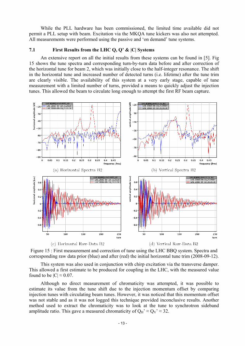
7.1 First Results from the LHC Q, Q’ & |C| Systems An extensive report on all the initial results from these systems can be found in [5]. Fig
15 shows the tune spectra and corresponding turn-by-turn data before and after correction of the horizontal tune for beam 2, which was initially close to the half-integer resonance. The shift in the horizontal tune and increased number of detected turns (i.e. lifetime) after the tune trim are clearly visible. The availability of this system at a very early stage, capable of tune measurement with a limited number of turns, provided a means to quickly adjust the injection tunes. This allowed the beam to circulate long enough to attempt the first RF beam capture.
Figure 15 : First measurement and correction of tune using the LHC BBQ system. Spectra and corresponding raw data prior (blue) and after (red) the initial horizontal tune trim (2008-09-12). This system was also used in conjunction with chirp excitation via the transverse damper. This allowed a first estimate to be produced for coupling in the LHC, with the measured value found to be |C| ≈ 0.07. Although no direct measurement of chromaticity was attempted, it was possible to estimate its value from the tune shift due to the injection momentum offset by comparing injection tunes with circulating beam tunes. However, it was noticed that this momentum offset was not stable and as it was not logged this technique provided inconclusive results. Another method used to extract the chromaticity was to look at the tune to synchrotron sideband amplitude ratio. This gave a measured chromaticity of QH’ ≈ QV’ ≈ 32.

- 14 -
7.2 Outlook for the LHC Q, Q’ & |C| Systems The next step required to fully commission the LHC tune, chromaticity and coupling systems will be to turn on and optimise the PLL tune systems. This will allow chromaticity measurement via RF modulation and also the first attempts at tune, coupling and chromaticity feedback. The other special transverse and longitudinal monitors, namely the head-tail/instability monitors, the wall current monitors and the Schottky monitors remain to be fully commissioned.
8. THE LHC FAST TIMING SYSTEM The LHC beam synchronous timing (BST) was developed using the TTC technology developed for the LHC experiments [6] as a means of supplying the beam instrumentation with 40MHz bunch synchronous triggers and the 11kHz revolution frequency. In addition to these two basic clocks, the TTC system also provides the possibility of encoding a message which can be updated and transmitted on every LHC turn. 8.1 Layout of the BST System The complete BST system consists of:
• one BST Master per LHC ring used to broadcast synchronisation signals and messages.
• the TTC transmission system used to encode and transmit signals over an optical link.
• a receiver interface, the BOBR, installed in each beam instrumentation crates that recovers the clocks and BST messages and provides all the timing signals required to synchronize the instruments.
8.2 The BST Messages The BST messages transmitted every turn clock are mainly used by the LHC instrumentation to trigger and correlate acquisitions. During the initial LHC run it was used for the following:
• Beam Position System - triggering regular orbit measurements, on-request capture measurements and for post mortem acquisition
• Beam Loss System - for post mortem acquisition
• Fast Beam Current Transformer - for on-request capture acquisitions All these events are directly derived from central timing events or RF injection pre-pulses. The BST systems take care of all transmission delays and of the receiver synchronisation to ensure all acquisitions made are for the same turn and bucket.
The BST messages will eventually also contain the current machine status and values of various beam parameters. This latter information has also proven to be of interest for the LHC experiments. The layout of the message and the boundaries of responsibility between the BI Group and each of the LHC experiments in this domain have been agreed upon and are documented in [7]. These parameters are obtained from the LHC central timing system and are retransmitted through the BST channels to the BI equipment and the experiments.
8.3 The Available Tools In addition to expert programs a dedicated diagnostic program was developed to check
the entire transmission chain from the masters to every operational receiver. Besides

- 15 -
systematic status verification, this program also sends a diagnostic bit in the BST message and checks that every receiver received the information at the same time. This test program was designed to support the LHC sequencer interface. It will eventually be integrated into the sequencer to verify the Beam Synchronous Timing system before each fill.
8.4 The First Results from the BST During the few days of operation with beam it was possible to successfully assess
most of the BST Master functionality, including delay tuning, time-stamping and central timing data re-transmission. The BST Receiver functionality was also successfully tested on the BPM, BLM and fast BCT systems. For all of these systems it was possible to trigger the different acquisition modes through the BST, including the ones linked directly to the RF injection pre-pulses.
These results are extremely encouraging but some time with beam will still be needed at the start of the next run to set-up and automate the fine delay tuning of bunch-by-bunch acquisition and to assess the long term stability of the system.
References
[1] E. Calvo-Giraldo et al., “The LHC Orbit and Trajectory System”, presented at DIPAC 2003, Mainz, Germany, 5 - 7th May 2003. CERN-AB-2003-057 BDI.
[2] D. Cocq, “The wide band normaliser – a new circuit to measure transverse bunch position in accelerator and colliders”, Nuclear Instruments and Methods in Physics Research A 416 (1998) p.1-8.
[3] S. Burger and E. Bravin, “A new Control System for the CERN TV Beams Observation”, CERN-AB-Note-2008-041-BI.
[4] T. Lefèvre et al., “A Large Scintillating Screen for the LHC Dump Line”, presented at DIPAC’07, Venice-Mestre/IT, 20-23 May 2007. CERN-AB-2007-023 BI.
[5] R. J. Steinhagen et al., “First Results from the LHC BBQ Tune and Chromaticity Systems”, LHC-Performance-Note-007 (2009).
[6] S. Baron, “TTC challenges and upgrade for the LHC”, presented at LECC 2005, Heidelberg.
[7] R. Jones, “The interface and structure of the machine beam synchronous timing system message for the LHC Experiments”, LHC-BOB-ES-0001, https://edms.cern.ch/document/638899 .